


Diaphragm Vacuum Pump
PK 800 202 B N/D (0501)
MVP 030
MVP 015-4
Betriebsanleitung • Operating Instructions

2
1. Safety Precautions .................................. 3
1.1. For Your Orientation........................................................... 3
1.2. Pictogram Definitions........................................................ 3
2. Understanding The Pump........................ 4
2.1 Main Features..................................................................... 4
2.2. Differences Between The Pump Types.......................... 4
3. Installation ............................................... 5
3.1. Setting Up The Pump And Location ................................ 5
3.2. Connecting The Vacuum Side.......................................... 5
3.3. Connecting The Exhaust Side .......................................... 5
3.4. Connecting To Mains Power............................................ 5
4. Operations ................................................ 6
4.1. Important Information ....................................................... 6
4.2. Switching ON/OFF The Pump........................................... 6
4.2. Intermittent Operations..................................................... 6
5. What To Do In Case Of Breakdown?...... 7
6. Maintenance ............................................ 8
6.1. Precautionary Measures During Maintenance Work ..8
6.2. Cleaning And Replacing Valves And Membranes.........8
6.3. Dismantling The Pump ...................................................... 8
6.4. Assembling The Pump....................................................... 8
7. Service .................................................... 10
8. Technical Data ....................................... 11
8.1. Substances Which Come Into Contact With The
Medium.............................................................................. 11
8.2. Dimensions........................................................................ 12
9. Spare Parts ............................................. 12
10. Accessories............................................ 12
Contamination Declaration ......................... 14
Conformity Declaration ................... last page
Index
Page
Please note:
Current operating instructions are also available via
www.pfeiffer-vacuum.net.

3
Danger of damage to the pump or system.
CAUTION
1. Safety Precautions
☞ Read and follow all the instructions in this manual.
☞ Inform yourself regarding:
☞ Hazards which can be caused by the pump;
☞ Hazards which can arise in your system;
☞ Hazards which can be caused by the medium being
pumped.
☞ Avoid exposing any part of the body to vacuum.
☞ Observe all safety and accident prevention regulations.
☞ Check regularly that all safety requirements are being
complied with.
☞ Do not carry out any unauthorised conversions or
modifications on the pump.
☞ When returning the pump to us please note the shipping
instructions in Section 7.
☞ Do observe strictly the proper use.
Danger of personal injury.
WARNING
Modifications reserved
1.2. Pictogram Definitions
Danger of burns from touching hot parts.
WAR N IN G
1.1. For Your Orientation
Instructions in the text
➡ Operating instructions: Here you have to do something!
Symbols used
The following symbols are used throughout in the
illustrations:
Vacuum flange
Exhaust flange
Power supply connection
Position numbers
Identical components and accessories parts have the same
position numbers in all illustrations.
Attention to particularly important information
on the product, handling the product, or to a
particular part of the documentation.
☞
PLEASE NOTE
Danger of an electric shock.
WAR N IN G
Proper use
–The Diaphragm Pump MVP 015-4/030 may only be used for
the purpose of generating vacuum.
–Do not pump corrosive or explosive gases.
– Do not pump liquids.
–Do not operate the pump in locations where there is an
explosion hazard.
–Accessories other than those named in this manual may
not be used without the agreement of Pfeiffer Vacuum.
– Do not use the connecting line between the heads of the
pump as a handle.
– Equipment must be connected only to a suitable fused and
protected electrical supply and a suitable earth point.
–Ensure that installation is in compliance with limitations
from the degree of protection, see section “Technical
Data“.
Improper Use
The following are regarded as improper:
–The pumping of corrosive gases (except with corrosive
gas processes version).
–The pumping of explosive gases.
–Operating the pump in locations where there is an explosi-
on hazard (a special version for this application is
available on request).
– The pumping of gases which are contaminated with
particles, dust and condensate.
–The Pump may not be used for the purpose of generating
pressure.
– The pumping of liquids.
–Connection to pumps and units which is not permitted
according to their operating instructions.
– Connection to units which contain touchable and voltage
carrying parts.
IImmpprrooppeerr uussee wwiillll ccaauussee aannyy rriigghhttss rreeggaarrddiinngg lliiaabbiilliittyy aanndd
gguuaarraanntteeeess ttoo b
bee ffoorrffeeiitteedd..

4
2. Understanding The Pump
2.1. Main Features
2.2. Differences Between The Pump Types
Features Unit MVP 030 MVP 015-4
Volume flow rate
at 1000 mbar and
50 Hz l/min 20 15
Pump stages three-stage four-stage
Connection of the 1-->2 in parallel 1-->2 in series
membrane heads 3-->4 in series 3-->4 in series
Final pressure
at 50 Hz mbar < 1.0 < 0.5
Mains connection Connecting cable hard-wired in
terminal box, without mains switch
MVP 030
MVP 015-4
Diaphragm Vacuum Pump MVP 015-4
1Membrane head 1
2Membrane head 2
3Membrane head 3
4Membrane head 4
5Vacuum flange (direct screw joint
6Voltage supply
7Exhaust (silencer)
9Capacitor
74 9 63
51
2
The diaphragm pump can be applied in all areas where an oilfree, dry vacuum is required.
Particularly the pump is suitable as backing pump for many
Pfeiffer Vacuum turbopumps in applications involving light
gas loads only.
Further applications:
–Pumping stations
–Plants
Research
Laboratories
Analytical
Chemistry
Leak detection

5
3. Installation
3.1. Setting Up The Pump And Location
➡ Place pump on a smooth, even surface.
➡ Anchor the pump if it is to be erected in a stationary positi-
on.
➡ Avoid mechanical stresses due to rigid connections. Insert
elastic hoses or resilient elements as couplings between
the pump and rigid pipes.
➡ Anchoring is not necessary if the pump is not erected in a
stationary position.
➡ Maximum ambient temperature +12 ... +40 °C.
➡ Where rack installation is involved, ensure adequate venti-
lation. If pump is installed above 1000 m above mean sea
level check compatibillity with applicable safety require-
ments, e. g. DIN VDE 0530 (motor may overheat due to
insufficient cooling).
3.2. Connecting The Vacuum Side
– Remove locking cap on intake connection.
– Make connection between the vacuum system and pump
as short as possible.
–Connect pump with intake connection to the apparatus.
–If liquid - which would generate vapours - is present in the
system to be evacuated, a condensate trap must be fitted
upstream of the pump.
3.3. Connecting The Exhaust Side
Pressure can rise to dangerous levels in exhaust
lines. Therefore, lay exhaust side lines without
shut-off units. Do not connect the exhaust side
with a closed system on account of the danger
of bursting.
In certain applications, exhaust gases and vapours can be
very hot and represent a health and/or environment hazard.
Lay lines from the pump sloping downwards so that
condensate cannot run back into the pump, otherwise fit a
separator.
3.4. Connecting To Mains Power
The pump is driven by AC motors with the following possible
variants:
230 V + 5% / -10%, 50 Hz
120 V + 5% / -10%, 60 Hz
Power connections must comply with local
regulations. Voltage and frequency information
given on the rating plate must correspond to the
mains voltage and frequency values. The pump
may only be connected to mains current with
earthed conductor.
WAR N IN G
CAUTION
Pump versions where the thermostatic winding
protection protrudes must be appropriately
wired to ensure the motor is protected.
CAUTION
Normal version
Motor
6
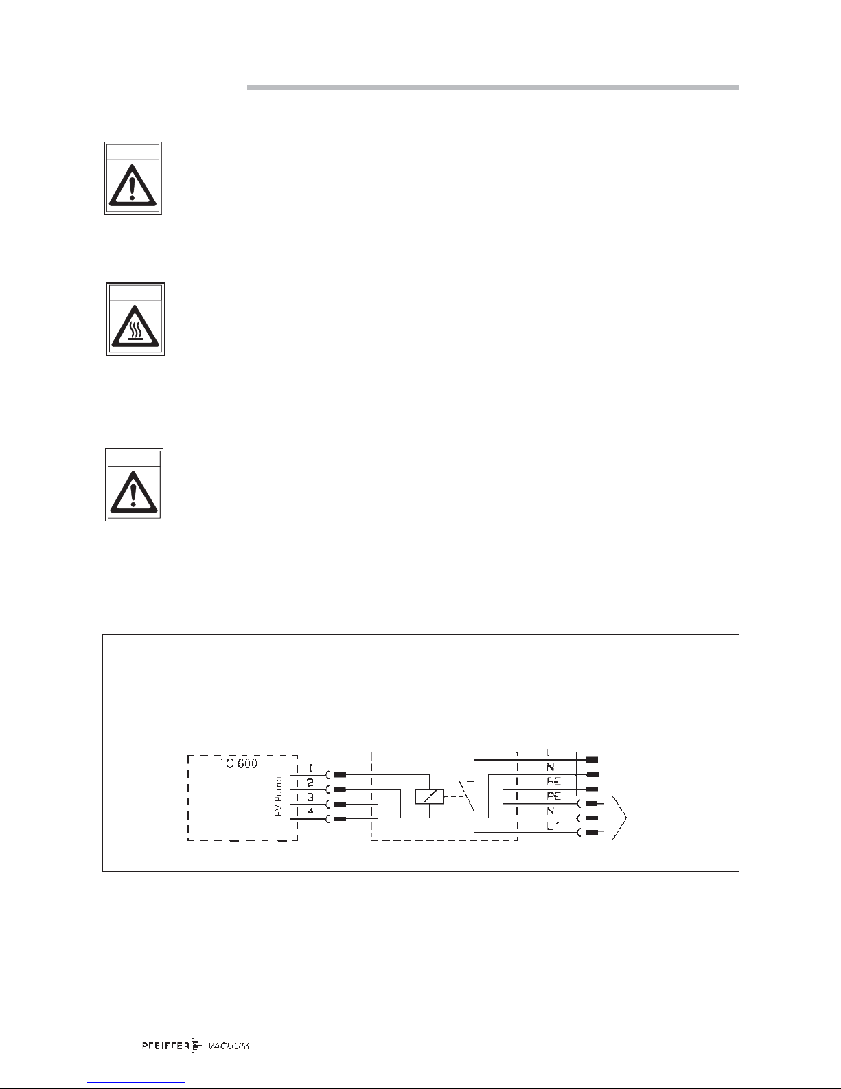
4.3 Intermittent Operations
To prolong the life of diaphragm pumps, intermittent
operations can be selected with lesser gas throughputs of
< 0.18 mbar l/s. This means that, dependent on the turbo
pump power take-up, the backing pump will be switched on
and off. Turbo pump power take-up is dependent on the forevacuum pressure and gas throughput.
–By comparing the power take-up with an upper and a
lower limit value, the relative switch-on duration with
lesser gas throughputs can be reduced to approx. 1 to 60%
–To avoid too frequent switching on, the buffer volume in
the fore-vacuum line should amount to < 0.5 liter from
approx. 0.018 mbar l/s.
Possible intermittent operations variations are shown in the
following diagram:
Connection of Diaphragm Vacuum Pump with with relay box on TC 600 for intermittent operations
roughing pump
MVP series
Relaybox
PM 041 937 GT
4. Operations
4.1. Important Information
Before starting, ensure that impermissibly high
pressures cannot build up on the pressure side.
Interchanging the connections causes
dangerous excess pressure levels.
The pumps should only start, when the pressure difference is max. 1 bar between admission and exhaust,
because the motor will be blocked and damage.
When the pump is running, surfaces and motor
casing become hot.
WAR N IN G
CAUTION
4.2 Switching ON/OFF The Pump
The pump can be switched on and off at all times.
Prevent internal condensation, transfer of
liquids or dust. The diaphragm and valves will
be damaged, if liquids are pumped in significant
amount over lengthy periods!
If the pump is subjected to condensates it
should be allowed to run for a few minutes
under atmospheric pressure before switching
off.
CAUTION

7
5. What To Do In The Case Of Breakdowns ?
PPrroobblleemm PPoossssiibbllee ccaauussee RReemmeeddyy
Pump does not attain final pressure
•
Condensate in the pump
•
Run pump for a longer period under
atmospheric pressure
•
Valves/diaphragms defective/dirty •Clean or replace valves and diaphragms,
see section 6.
•
Leak in system
•
Repair leak
Unusual operating noises Valves/diaphragms defective See maintenance in section 6.
Dirt in the working chamber Clean working chamber.
Silencer loose or missing Check silencer; clean or replace.
Valves defective Change valves.
Motor fan defective Change motor fan.
Con-rod or motor bearing defective Inform Pfeiffer-Service.
Pump does not start No mains voltage Check power supply.
Phase failure Check fuse.
Motor overheating Allow the motor to cool down and
depress mains switch off/on.
Ambient temperature < 12 °C Warm pump.
Dirty valves/diaphragms See maintenance in section 6.
Over-pressure in the exhaust line Open exhaust line (open exhaust valve).
Pump switches off
•
Sticking diaphragms
•
Clean pump (see section 6.)
•
Wrong mains voltage
•
Correct as per rating plate
8
6. Maintenance
6.1. Precautionary Measures During Maintenance Work
Whenever working on the pump ensure the
motor cannot get switched on.
If necessary, remove pump from the system for
inspection. Before dismantling allow the pump
to cool down.
➡ Only dismantle the pump as far is necessary to effect
repairs.
➡ Use only benzin or the like for cleaning. Do not use
solvents.
6.2. Cleaning And Replacing Valves And
Membranes
Under normal operating conditions, the pump is maintenance
free. The valves and the diaphragms are wear parts. If the
rated ultimate vacuum is no longer achieved, the pump interior, the diaphragms and the valves must be cleaned and the
diaphragms and valves must be checked for cracks or other
damage.
Depending on individual cases it may be efficient to check
and clean the pump heads on a regular basis. In case of
normal wear the
lliiffeettiimmee ooff tthhee ddiiaapphhrraaggmmss aanndd vvaallvveess iiss >>
1100000000 ooppeerraattiinngg hhoouurrss
.
There can be different numbers of washers 17
in each membrane head. Ensure the correct
assignment for mounting when dismantling the
membrane heads. Don’t confuse the washers
17.
6.3. Dismantling The Membrane Head
➡ Allow the pump to cool down before dismantling.
➡ Using an SW 14 key, unscrew direct screw joint (20) of
interhead connection (10) on diaphragm head 1 (see marks
on the housing).
➡ As far as possible place pump on its side so that the head
to be dismantled points up.
➡ Using an SW 3 key, unscrew the four Allan head screws
(11) and remove head cover (12), taking care with the two
valve plates (13) and sealing rings (14).
➡ Remove intermediate plate (15).
➡ Use a small screwdriver to carefully ease out diaphragm
(16) and manually unscrew from the connecting rod (righthand thread). Look out for possible washers (17).
➡ Clean all parts with alcohol and examine diaphragms,
valves and seals for possible damage and renew as
necessary. If a new diaphragm is to be fitted, the washers
(17) of the old diaphragm must be used again otherwise
the pump will not attain the required pressure.
CAUTION
CAUTION
6.4. Assembling The Membrane Head
➡ Assemble all parts in reverse order. The connecting rod
should be positioned in the upper dead point when fitting
the diaphragm. Ensure correct positioning of all parts.
➡ Check correct sealing ring seating.
➡ Re-make hose connection and re-tighten direct screw
joint (20).
➡ Test pump for function.

9
11 12 13 14
15 16 17
Dismantling the membrane head
11 Allan head screw
12 Head cover
13 Valve plate
14 Sealing ring
15 Intermediate plate
16 Diaphragm
17 Washer
9 4 10a 1
11120 10 2 7 5
1Membrane head 1
2Membrane head 2
4Membrane head 4
5Vacuum flange (direct screw
joint)
7Exhaust (silencer)
9Capacitor
10 Interhead connection 1-2
10a Interhead connection 2-3
11 Allan head screw
20 direct screw joint

10
7. Service
Repair orders are carried out according to our
general conditions of sale and supply.
➡ If repairs are necessary, please send the unit together
with a short damage description to your nearest Pfeiffer
Vacuum Service Center.
☞
PLEASE NOTE
Do Make Use Of Our Service Facilities
In the event that repairs are necessary to your pumping
station, a number of options are available to you to ensure
any system down time is kept to a minimum:
–Have the pump repaired on the spot by our Pfeiffer
Vacuum Service Engineers;
–Return the individual components to the manufacturer for
repairs;
– Replace individual components with a new value
exchange units.
Local Pfeiffer Vacuum representatives can provide full
details.
Before Returning:
➡ Dismantle all accessories.
➡ Attach a clearly visible notice: “Free of contamination” (to
the unit being returned, the delivery note and accompany-
ing paperwork).
Harmful substances" are substances and preparations as
defined in current legislation. Pfeiffer Vacuum will carry out
the decontamination and invoice this work to you if you have
not attached this note. This also applies where the operator
does not have the facilities to carry out the decontamination
work. Units which are contaminated microbiologically, explosively or radioactively cannot be accepted as a matter of
principle.
Fill Out The Contamination Declaration
➡ In every case the "Contamination Declaration" must be
completed diligently and truthfully.
➡ A copy of the completed declaration must accompany the
unit; any additional copies must be sent to your local
Pfeiffer Vacuum Service Center.
Please get in touch with your local Pfeiffer Vacuum representatives if there are any questions regarding contamination.
Decontaminate units before returning or
possible disposal. Do not return any units which
are microbiologically, explosively or radioactively contaminated.
Returning Contaminated Units
If contaminated units have to be returned for
maintenance/repair, the following instructions concerning
shipping must be followed without fail:
➡ Neutralise the pump by flushing with nitrogen or dry air.
➡ Seal all openings to the air.
➡ Seal pump or unit in suitable protective foil.
➡ Ship units only in appropriate transport containers.
WARNING

11
8. Technical Data
SSiizzee UUnniitt MMVVPP 003300 MMVVPP 001155--44
Connections
Intake side DN 16 ISO-KF/G 1/8“ G 1/8“+silencer
Pressure side DN 16 ISO-KF/G 1/8 G 1/8“+silencer
Nominal volume flow rate at 1000 mbar
50 Hz l/min 20 15
60 Hz l/min 24 18
Volume flow rate at 10 mbar
50 Hz l/min 6 4
60 Hz l/min 7 4,5
Final pressure mbar ≤ 1.0 ≤ 0.5
Permissible exhaust pressure mbar 1050 1050
Leakrate to vacuum chamber
when pump is switched off mbar l/sec ≤ 5.10
-3
≤ 5.10
-3
Integral Leakrate mbar l/sec ≤ 1.10
-3
≤ 1.10
-3
Max. operating altitude (a. s. l.) m approx. 2000 approx. 2000
Max. permissible gas- and
environment temperature °C +12 ... +40 +12 ... +40
Overload protection
(coiled temperature switch) °C 118 118
Noise level dB(A) ca. 52 ca. 52
Motor (insulation material class B) IP 54 IP 54
Power at 230 V 50 Hz W 80 80
Power at 115 V 60 Hz W 80 80
Weight, approx. kg 7.5 7.5
PPuummpp ccoommppoonneennttss SSuubbssttaanncceess iinn ccoonnttaacctt wwiitthh tthhee mmeeddiiaa
((
MVP 030, MVP 015-4)
Diaphragm EPDM
Valves EPDM
Pump head Aluminium
Tupe PVC
Swivelling screw-fitting Aluminium
Silencer Polyamide
8.1. Substances Which Come Into Contact
With The Medium

12
8.2. Dimensions
9. Spare Parts
When ordering accessories and spare parts please be sure to state the full part number. When ordering spare parts please state
additionally the unit type and unit number (see rating plate). Please use this list as an order form (by taking a copy).
PPooss.. DDeessccrriippttiioonn PPiieecceess SSiizzee NNuummbbeerr CCoommmmeennttss//rreelleevvaanntt OOrrdd.. QQuuaannttiittyy
MMVVPP 003300 MMVVPP 001155--44
Spare parts pack contains 2 PK 050 094 -AT not included in the
all necessary wear parts: delivery consignment
7 Silencer 1 PO 920 791 E not included in the
delivery consignmen
10.Accessories
PPooss.. DDeessccrriippttiioonn PPiieecceess SSiizzee NNuummbbeerr CCoommmmeennttss//rreelleevvaanntt OOrrdd.. QQuuaannttiittyy
Relaybox roughing pumps, 1 phas. 5A for 1 94 x 65 x 57 (mm) PM 041 937 GT not included in the
connection on TC 600 or TC 100 with delivery consignment
TCS 010

13
Tradename Chemical name Danger class Precautions associated Action if spillage or human
Product name (or Symbol) with substance contact
Manufacturer
1.
2.
3.
4.
5.
5. Legally Binding Declaration
I hereby declare that the information supplied on this form is complete and accurate. The despatch of equipment will be in
accordance with the appropriate regulations covering Packaging, Transportation and Labelling of Dangerous Substances.
Name of Organisation: _______________________________________________________________________________
Address: _____________________________________ Post code: _____________________________________
Tel.: ______________________________________________________________________________________
Fax: _____________________________________ Telex: ________________________________________
Name: ______________________________________________________________________________________
Job title: ______________________________________________________________________________________
Date: _____________________________________ Company stamp: ________________________________
Legally binding signature: _____________________________________________________________________________
Declaration of Contamination of Vacuum Equipment and Components
The repair and/or service of vacuum components will only be
carried out if a correctly completed declaration has been
submitted. Non-completion will result in delay.
The manufacturer could refuse to accept any equipment
without a declaration.
This declaration can only be completed and signed by authorised and qualified staff:
1. Description of component:
- Equipment type/model: _________________________
- Code No.: __________________________
- Serial No.: __________________________
- Invoice No.: __________________________
- Delivery Date: __________________________
3. Equipment condition
- Has the equipment been used?
yes ❐ no ❐
- What type of pump oil was used?
___________________________________________
-Is the equipment free from potentially harmful
substances?
yes ❐ (go to section 5)
no ❐ (go to section 4)
4. Process related contamination
of equipment
-toxic yes ❐ no ❐
-corrosive yes ❐ no ❐
- microbiological hazard*) yes ❐ no ❐
-explosive*) yes ❐ no ❐
-radioactive*) yes ❐ no ❐
-other harmful substances yes ❐ no ❐
*) We will not accept delivery of any equipment that has been radioactively or microbiologically contaminated without written
evidence of decontamination!
2. Reason for return:
_____________________________________________
_____________________________________________
_____________________________________________
_____________________________________________
_____________________________________________
Please list all substances, gases and by-products which may have come into contact with the equipment:
14
im Sinne folgender EU-Richtlinien:
pursuant to the following EU directiv es:
- Maschinen/
Machinery
98/37/EG (Anhang/
Annex
IIA)
- Elektroma gnetische Verträglichkeit/
Electromagnetic Compatibility
89/336/EWG
- Niederspannung/
Low Voltage
73/23/EWG
Hiermit erklären wir, dass das unten aufg eführte Produkt den Bestimm ungen d er EU-Maschinenrichtlinie 98/37/E G, der EU-Richtlinie über Elektro magnetisch e Verträglichkeit 89/336/EW G und der
EU-Nie d erspannun gsrichtlinie 73/23/E W G e ntspricht.
We hereby c ertify, that the product specified belo w is in accordance with the provision of EU Machin ery
Directive 98/37/EEC, EU Electro magentic Co mpatibility Directive 89/336/EEC and E U Lo w Voltage
Directive 73/23/EEC.
Produkt/
Produc t
:
MMVVPP 0033 00
MMVVPP 00 11 55 --22
Angew e n det e Richtlinien, harmonisierte Normen u n d ange wen d ete nationale Norm e n:
Guidelines, harmonised standards, national standards w hich h a v e been applied:
DDIINN EENN IISSOO 1122110000--11 DDIINN EENN IISSOO 1122110000--22
EENN 5555 001144 EENN 5500 008811--11
EENN 229944 EENN 5500 008822--11
EENN 6600 220044--11 EENN 6600 555555--22,, -
-33
EENN 6600 333355--11 EENN 11001122--22
Unterschrift/
Signature:
Unterschriften:
(W. Dondorf)
Geschäftsführer
Managing Director
Pfeiffer Vacuum GmbH
Berliner Str. 43
35614 Asslar
Germany
Konformitätserklärung
Declaration of Conformity
Konf.I/2003

Pfeiffer Vacuum Technology AG · Headquarters/Germany
Tel. +49-(0) 64 41-8 02-0 · Fax +49-(0) 64 41-8 02-2 02 · info@pfeiffer-vacuum.de · www.pfeiffer-vacuum.net
Yo u r V a c u u m Te c h n o l o g y E x p e r t s i n
Tu r b o P u m p s
Rotary Vane Vacuum Pumps
Roots Pumps
Dry Vacuum Pumps
Leak Test Units
Val ves
Flanges, Feedthroughs
Vacuum Measurement
Gas Analysis
System Technology
Service
 Loading...