

Pfeiffer Vacuum MaxiGauge TPG 256 A PT G28 760, MaxiGauge TPG 256 A PT G28 761 Operating Instructions Manual

A PASSION FOR PERFECTION
TPG 256 A
MaxiGauge™, vacuum measurement and control unit for Compact
Gauges
Operating Instructions
BG 5186 BEN / C (2013-12)

Validity
Firmware Version
Trademarks
This manual applies to products with part number:
• PT G28 760 with serial interfaces RS232C and
RS422
• PT G28 761 with serial interfaces RS232C and
RS422 and RS485 (addressable,
isolated) and RS422 (isolated)
The part number can be taken from the nameplate on
the rear panel, where the interfaces can be connected
as well (→ 12).
This manual is based on firmware version:
• BG 509 730 -K
If your unit does not behave as described in this document, please check whether it is equipped with this firmware version (→ 110).
Enter the firmware version number of your unit in the
space provided below:
• BG ..................... ..................... -.......
MaxiGauge™ INFICON GmbH
FullRange™ INFICON GmbH
We reserve the right to make engineering changes without notice.
2
BG 5186 BEN / C (2013-12) MaxiGauge.om

Contents
Validity 2
Firmware Version 2
Trademarks 2
Intended Use 6
1
2 Technical Data 8
3 Safety 15
4 Commissioning 17
4.1 Personnel 17
4.2 Set-Up, Assembly 17
4.3 Power Connection 18
4.4 Connecting the Gauges to sensor 21
4.5 control Control Connector 21
4.6 RS 232/422 Pinout Connector for Serial
Interfaces 23
4.7 RS 485/422 isol. Interface Port 23
4.8 relay Connector for Switch Contacts 23
5 Operating Elements and Modes 24
5.1 Operating Elements 24
5.2 Operating Modes (Overview) 27
5.2.1 «Measurement» Mode 28
5.2.2 «Setpoint» Mode 30
5.2.3 «General Parameter» Mode 31
5.2.4 «Sensor Parameter» Mode 32
5.2.5 «Sensor Control» Mode 33
5.2.6 «Test» Mode 34
6 Display Formats and Pressure Units 35
6.1 Display Formats 35
6.2 Pressure Units 36
6.3 Cursor 36
7 Operation 37
7.1 Personnel 37
7.2 Switching the Unit On and Off 37
7.3 Selecting the Operating Mode 39
7.4 «Measurement» Mode 40
7.4.1 Selecting the Measurement Point (Sensor) 40
7.4.2 Switching the Gauge On/Off (Sen-on/off) 41
7.4.3 Display of a Single Gauge / All Gauges
(Single/All) 41
7.5 «Setpoint» Mode 42
7.5.1 Selecting the Switching Function (Relay) 42
7.5.2 Assigning Measurement Points (Control
Sensor) 43
7.5.3 Defining the Threshold Values (Setpoint) 44
7.5.4 Underrange Control (UR-Control) 46
BG 5186 BEN / C (2013-12) MaxiGauge.om Contents 3

7.6 «General Parameter» Mode 48
7.6.1 Parameter Input Lock (Key-lock) 48
7.6.2 Selecting the Pressure Unit (Unit) 49
7.6.3 Display Resolution (Digits) 50
7.6.4 Bargraph (Bargraph) 51
7.6.5 Restoring Default Values (Default) 52
7.6.6 Defining an Interface (Interface) 53
7.6.7 Defining the Baud Rate (Baudrate) 54
7.6.8 Defining the Node Address (Address) 55
7.6.9 Screensave (Screensave) 56
7.6.10 Display Contrast (Contrast) 57
7.7 «Sensor Parameter» Mode 58
7.7.1 Selecting a Measurement Point (Sensor) 58
7.7.2 Gauge Identification (Type) 59
7.7.3 Offset Function (Offset) (zeroing) 60
7.7.4 Activating the Degas Routine (Degas) 63
7.7.5 Pirani Range Extension (Range-Ext) 64
7.7.6 Setting the Calibration Factor (Cal-Factor) 65
7.7.7 Setting the Measurement Value Filter (Filter) 66
7.7.8 Defining the Measurement Point Name
(Name) 68
7.8 «Sensor Control» Mode 69
7.8.1 Selecting the Controlled Gauge (Sensor) 71
7.8.2 Selecting the Controlling Source (Control) 71
7.8.3 Setting the «Sensor 1 ... 6» Control 72
7.8.4 Setting the «Extern» Control 72
7.8.5 Setting the «Manual» Control 73
7.8.6 Setting the «Hotstart» Control 74
7.9 Status Messages 75
7.10 Error Messages 77
8 Communication 80
8.1 Serial Interfaces 80
8.1.1 Connection Diagrams 80
8.1.2 Connection Cable 81
8.1.3 Data Transmission 82
8.2 Mnemonics 86
8.2.1 Measurement Values 87
8.2.2 Display 90
8.2.3 Switching Functions 91
8.2.4 Parameters 92
8.2.5 Interfaces 95
8.2.6 Error Messages 98
8.2.7 Test Programs for Pfeiffer Vacuum Service
Specialists 99
4
Contents BG 5186 BEN / C (2013-12) MaxiGauge.om

9 Maintenance and Care 103
9.1 Personnel 103
9.2 Cleaning 103
9.3 Maintenance 104
10 Accessories and Spare Parts 105
11 Decommissioning 107
Appendix 108
A: Validity Table 108
B: Conversion of Pressure Units 109
C: Equipment Test 109
D: Literature 113
EC Declaration of Conformity 116
For cross references to pages within this manual, the
symbol (→ XY) is used, for references to other docu-
ments, the symbol (→ [Z]).
BG 5186 BEN / C (2013-12) MaxiGauge.om Contents 5

1 Intended Use
The TPG 256 A TPG 256 A is a 6-port total pressure
measurement and control unit for Pfeiffer Vacuum Compact Gauges.
The unit has been engineered for use with the following
gauge families *
)
:
• TPR Pirani gauge
• PCR Combined Pirani/Capacitance gauge
• IKR Cold cathode gauge
• PKR Combined Pirani/cold cathode gauge
• IMR Hot ionization gauge High Pressure
(HP)
• PBR Combined Pirani/Bayard-Alpert hot
cathode ionization gauge (BA)
• CMR/ACR Capacitive gauge
• APR Piezoresistive gauge
The unit is suited for total pressure measurement in the
range of 10
-11
mbar to 50 bar (5×10⁴ mbar). Through its
pressure dependent switching functions and the userprogrammable sensor control it can also perform a number of functions for controlling and monitoring vacuum
equipment and processes.
DANGER
Although this unit conforms to high quality and safety
standards and has been built and tested in accordance with current technology, bodily injury and property damage cannot be precluded if it is used in nonconforming applications (for purposes other than intended) or if it is not used with diligence.
Therefore, it is essential that you carefully study this
operating manual, especially the chapter "Safety".
Keep this operating manual in a convenient location
near your equipment.
6
BG 5186 BEN / C (2013-12) TPG 256 A

Figure 1:
Dimensions
Figure 2:
Nameplate
A Width of front panel 241 mm (½ 19" rack width)
B Mounting horizontal 224 mm
C Mounting vertical 76.2 mm
D Height of front panel 88 mm (2 height units)
E Installed depth 228.5 mm
F Installed width 207 mm
G Installed height 88 mm (2 height units)
Pfeiffer Vacuum, D-35614 Asslar
Typ:
No:
F-No:
V Hz VA
The nameplate is located on the rear panel.
Make sure that the voltage and frequency ratings conform with the local power supply system. The remaining
information is important for communication with the
Pfeiffer Vacuum customer service.
BG 5186 BEN / C (2013-12) MaxiGauge.om Technical data 7
2 Technical Data
Mechanical data
Power connection
Environment, standards
Dimensions
Weight 2.1 kg
19" rack installation
Voltage 90 ... 250 VAC / 50 ... 60 Hz
Power consumption 60 VA
Overvoltage category II
Protection class 1
Unit connector IEC 320 C14
Power switch Rear panel
Temperatures
Storage
Operation
Relative humidity Max. 80 % up to +31°C,
Use Indoors only
Contamination severity II
Protection class IP 30
Safety
EMC
→ Figure 1
→ Accessories,
-20 ... +60 °C
+ 5 ... +40 °C
decreasing to 50 % at +40 °C
maximum height 2000 m
→ 116
105
8
Technical data BG 5186 BEN / C (2013-12) MaxiGauge.om

Figure 3:
Gauges
Logarithmic gauges
TPR
Compact Pirani Gauge
(Pirani gauge)
PCR
Compact Pirani Capacitance
Gauge
(Pirani/Capacitance gauge)
IKR
Compact Cold Cathode Gauge
(Cold cathode gauge)
PKR
Compact FullRange™ CC Gauge
(Pirani/Cold cathode gauge)
IMR
Compact Process Ion Gauge
(Pirani/High pressure gauge)
PBR
Compact FullRange™ BA Gauge
(Pirani/Bayard-Alpert gauge)
BG 5186 BEN / C (2013-12) MaxiGauge.om Technical data 9
Linear gauges
CMR/ACR
Compact Capacitance Gauge
(Capacitive gauge)
Gauge connections
APR
Compact Piezo Gauge
(Piezoresistive gauge)
Number 6
Compatible gauges
(→ [1] ... [18]
Compact Pirani Gauges
Compact Pirani Capacitance
Gauge
Compact Cold Cathode Gauges
Compact FullRange™ CC Gauges
Compact Process Ion Gauges
Compact FullRange™ BA Gauges
Compact Capacitance Gauges
Compact Piezo Gauges
Connector type, pin assignments
[18])
Pfeiffer Vacuum Compact
Gauges
TPR 250, TPR 260, TPR 261,
TPR 265, TPR 280, TPR 281
PCR 260, PCR 280
IKR 250, IKR 251, IKR 260,
IKR 261, IKR 270
PKR 250, PKR 251, PKR 260,
PKR 261
IMR 260, IMR 265
PBR 260
CMR 261, CMR 262, CMR 263,
CMR 264, CMR 271, CMR 272,
CMR 273, CMR 274, CMR 275;
CMR 361, CMR 362, CMR 363,
CMR 364, CMR 371, CMR 372,
CMR 373, CMR 374, CMR 375;
ACR 261, ACR 262, ACR 263,
ACR 274
APR 250, APR 260, APR 262,
APR 265, APR 266, APR 267
→ 20
With the exception of the IMR 265, PBR 260, CMR 27X
and CMR 37X, which can only be connected to ports 4 to
6, any compatible gauge type can be connected to any
analog output.
10
Technical data BG 5186 BEN / C (2013-12) MaxiGauge.om

Measured values
Gauge supply
Gauge control
Degas
Measurement ranges
Measurement error
Gain error
Offset error
→ Gauge
≤0.2 %
measurement signal
≤20 mV
Measurement rate 100 / s
Display rate 4 / s
Filter time constant
s
low
standard
fast
Voltage
Current
Sensor 1 to 3
Sensor 4 to 6
Fuse
Sensor 1 to 3
Sensor 4 to 6
2.1 s (f
320 ms (f
100 ms (f
= 0.075 Hz)
g
= 0.5 Hz)
g
= 1.6 Hz)
g
+24 VDC ± 5%
200 mA per gauge
600 mA per gauge
300 mA per gauge
1 A per gauge
(PTC element, self resetting after
unit is switched off)
Turning the gauge on / off
Manual
Automatic
Hot Start
External
Self-monitoring
Softkey (
Sen-on / Sen-off)
by gauge 1 ... 6 (
Sensor X)
(IKR, IMR by TPR, PKR, etc.)
adjustable setpoints, userassignable
IKR, PKR, IMR and PBR gauges
are turned on when the unit is
switched on
Individually for each gauge at the
«Control» connector
TTL high: +2 … 5 V = gauge off
TTL low: ≤+0.8 V = gauge on
Internal pull-up 3.3 kΩ to +5 V
IKR and IMR gauge turned off by
own measured value
Degas (PBR 260 only) Duration 3 min. (can be aborted)
BG 5186 BEN / C (2013-12) MaxiGauge.om Technical data 11

Figure 4:
Rear panel
67
1
5
1
5
6
6
234
234
1
5
6
234
ALCATEL, 7400 9 Annecy, France
Typ:
P/N:
S/N:
V Hz VA
1
5
6
1
5
234
1
5
6
6
234
234
2 9 1 84 35
TPG 256 A part number PT G28 760:
1
2
3
4
5
6
7
RS 232/422
relay
sensor 1 ...
... sensor 6
control
Pinout for serial interface RS232C or
RS422 (not isolated)
Connector for relay switch contacts
Power inlet 3-pin
Reference for fuses inside the unit
(replacement only by Pfeiffer Vacuum
Service)
Power switch
Connectors for gauges
Connector for control functions
TPG 256 A part number PT G28 761, additional features:
8,9
RS 485/422 isol.
Port for serial interface RS485
(addressable, isolated) and RS422
(isolated)
Connector types and pin assignments → 20 f.
12
Technical data BG 5186 BEN / C (2013-12) MaxiGauge.om
Switching functions
Error signal
Analog outputs
Computer interfaces
Number 6
Gauge assignment User-programmable
Response time 10 ms, if the measured value is
near the setpoint. For bigger differences, take the filter time constant into consideration.
Relay contacts Changeover switch, floating
Contact closed
Contact open
= 60 VDC / I
U
max
= 30 VAC / I
U
max
Vacuum better than setpoint
Vacuum worse than setpoint or
max
max
= 3 A
= 3 A
power switched off
Cycle life
mechanical
electrical
Connector type, pin assignment
7
5×10
cycles
1×10⁵ cycles
→ 22
Response time 10 ms
Relay contact Changeover switch, floating
U
Contact closed
Contact open
= 60 VDC / I
max
= 30 VAC / I
U
max
No error
Error or mains power switched
max
max
= 3 A
= 3 A
off
Cycle life
mechanical
electrical
Connector type, pin assignment
7
5×10
5
1×10
→ 22
cycles
cycles
Number 6 (1 per gauge)
Voltage range 0 ... +10 V
Internal resistance
Relationship measurement signal-pressure
Connector type, pin assignment
Standard
Option (for PT G28 760)
660 Ω
→ Gauge used
→ 20
RS232C
RS422, not isolated
RS485, addressable, isolated
RS422, isolated
Protocol
RS232C
RS422, RS485
Connector type, pin assignment
ACK/NAK, ASCII
with 3 character mnemonics,
bi-directional data flow (masterslave)
(additional information → 80)
Only TXD and RXD used
Only TX+, TX-, RX+, RX- used
→ 22
BG 5186 BEN / C (2013-12) MaxiGauge.om Technical data 13

Figure 5:
Symbols for residual hazards
DANGER
Information on preventing any kind of physical injury.
Figure 6:
Symbol for special personal
qualifications
WARNING
Information on preventing extensive equipment and
environmental damage.
Caution
Information on correct handling or use. Disregard can
lead to malfunctions or minor equipment damage.
Skilled personnel
All work described in this document may only be
carried out by persons who have suitable technical
training and the necessary experience or who have
been instructed by the end-user of the product.
14 Safety
BG 5186 BEN / C (2013-12) TPG 256 A

3 Safety
3.1 Personnel
3.2 Danger, Caution,
and Note Symbols
3.3 Safety Information
3.4 Responsibility and
Warranty
Skilled personnel
Work on and with the TPG 256 A TPG 256 A may only
be carried out by persons with suitable technical
training and the necessary experience.
The opposite symbols together with explanatory text are
used to point out residual dangers inherent in conforming utilization and to emphasize important technical requirements.
• Take into account the relevant safety regulations
when doing installing and maintenance work.
Pfeiffer Vacuum declines any liability, and the warranty
becomes null and void if the operator or third parties
• utilize the product not according to the defined use
• disregard the technical data
• make any kind of changes (modifications, alterations,
etc.) to the product
• use the product with accessories not listed in the
product documentation.
BG 5186 BEN / C (2013-12) MaxiGauge.om Safety 15

Figure 7:
Setup as desktop unit
Figure 8:
Connection cable
Make sure to provide for proper ventilation when using
the TPG 256 A as desktop unit. For this purpose, an
acrylic glass stand can be ordered as accessory
(→ Accessories 105).
Use a connection cable
with ground
conductor.
DANGER
If you can assume, for example for one of the
following reasons, that the unit is no longer safe to
operate, shut it down and secure it so that it cannot be
inadvertently turned on again:
a) the unit has sustained visible damage
b) it no longer functions
c) it has been stored for a longer period under unfa-
vorable conditions
d) it has been subjected to severe transport stress
DANGER
Any interruption of the protective ground inside or outside the unit, or disconnection of the protective ground
makes the equipment hazardous to operate (electric
shock).
16 Commissioning
BG 5186 BEN / C (2013-12) MaxiGauge.om

4 Commissioning
4.1 Personnel
4.2 Set-Up, Assembly
Skilled personnel
The unit may be put into service by skilled and suitably
trained persons only.
There are two possibilities for incorporating the unit into
a switching cabinet according to DIN 41 494:
a) Installation in a 19" rack frame (2 height units) to-
gether with a second unit or with a blanking plate
(
→ Accessories 105)
b) Installation in a 19" rack frame using an adapter
(3 height units, 63 length units, ¾ rack width)
→ Accessories 105)
(
Connection piece
PT 441 480-T
Blank panel
Direct installation in a 19"
frame
Installation with
an adapter
Maxi Gauge
Maxi Gauge
Frame width
Maxi Gauge
Maxi Gauge
PT 441 481
Adapter
PT 441 248-X
2 height units
Frame width
3 height units
With an acrylic glass stand (→ Accessories 106), it
can also be used as bench top unit.
Caution
Consider the specifications in the "Technical data"
with regard to the admissible ambient temperature, the
protection class and the voltages.
BG 5186 BEN / C (2013-12) MaxiGauge.om Commissioning 17

4.3 Power Connection
Before switching the unit on make sure that the operating voltage of the unit corresponds to the local line voltage. The power ratings are indicated on the product
nameplate on the rear panel of the unit.
Use only a 3-conductor power cable with protective
ground. The power connector may only be plugged into
a socket with a protective ground. This protection must
not be defeated by an extension cable without ground
conductor.
If the unit is to be installed in a rack, the power must be
supplied via a switched power distributor.
18 Commissioning
BG 5186 BEN / C (2013-12) MaxiGauge.om

Notes:
BG 5186 BEN / C (2013-12) MaxiGauge.om Commissioning 19

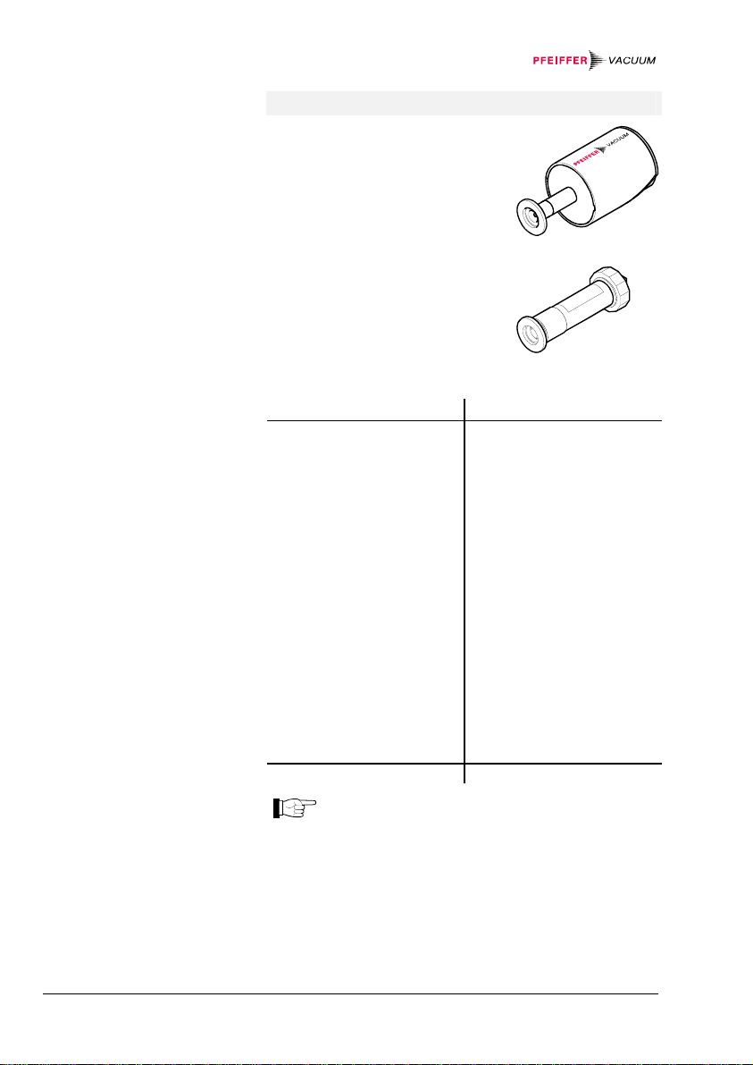
Figure 9:
Gauge connector sensor
Figure 10:
Control connector control
Pin assignment
1 Identification
2 GND
3 Measurement signal +
4 Measurement signal 5 Screen
6 Vcc
Pin assignment
1 Analog output sensor 1
2 Analog output sensor 2
3 Analog output sensor 3
4 Analog output sensor 4
5 Analog output sensor 5
6 Analog output sensor 6
7 GND
8 GND
9 GND
10 External control sensor 1
11 External control sensor 2
12 External control sensor 3
13 External control sensor 4
14 External control sensor 5
15 External control sensor 6
Amphenol C91B,
6-pin, female
6
5
4
1
2
3
Front view
D-Sub, high density,
15-pin, female
515110 6
11
Front view
20 Commissioning
BG 5186 BEN / C (2013-12) MaxiGauge.om

4.4 Connecting the
Gauges to sensor
4.5 control
Control Connector
Caution
Switch the unit off before connecting or removing any
gauges.
Connect the gauge to one of the six connectors sensor 1
… sensor 6 (PBR 260, IMR 265, CMR 27X and
CMR 37X only to sensor 4 … sensor 6) on the rear
panel of the unit by means of a shielded cable (electromagnetic compatibility). Connect only gauge types
specified in the "Technical Data".
Pre-fabricated connection cables as well as individual
parts for custom cable fabrication are available
(→ Accessories 105).
Configure the control connector as required. Plug it into
the control socket on the rear panel.
Caution
Use only shielded cables (electromagnetic compatibility).
BG 5186 BEN / C (2013-12) MaxiGauge.om Commissioning 21
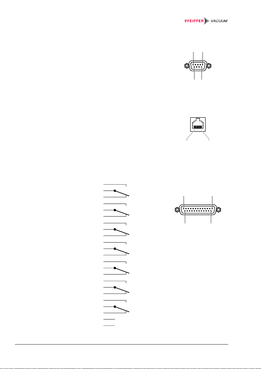
Figure 11:
RS 232/422
Pinout connector for serial
interfaces
Figure: 12
RS 485/422 isol.
Serial interface port
Figure 13:
relay
Connector for switch contacts
Pin assignment
1 Chassis
2 RXD (RS232C)
3 TXD (RS232C)
4 not connected
5 Signal Ground
6 RX+ (RS422)
7 RX- (RS422)
8 TX+ (RS422)
9 TX- (RS422)
Pin assignment
1 TX+
2 TX 3 RX+
4 not connected
5 not connected
6 RX 7 not connected
8 Isolation ground
Pin assignment
6
5
Relay A
4
10
9
Relay B
8
13
12
Relay C
11
18
17
Relay D
16
21
20
Relay E
19
24
23
Relay F
22
14
15
Error Relay
3
25
1.7
+24 V max. 200 mA
GND (Chassis)
D-Sub, 9-pin, male
165
9
Front view
RJ45, 8-pin
18
Front view
D-Sub, 25-pin,
female
13
25
1
14
Front view
22 Commissioning
BG 5186 BEN / C (2013-12) MaxiGauge.om
4.6 RS 232/422
Pinout Connector
for Serial Interfaces
4.7 RS 485/422 isol.
Interface Port
4.8 relay
Connector for
Switch Contacts
Connect the serial interface to the RS 232/422 pinout
connector on the back of the unit by means of a shielded
cable (electromagnetic compatibility).
Connect the serial interface to the RS 485/422 isol. port
on the back of the unit by means of a shielded cable
(electromagnetic compatibility).
The two connectors are linked 1:1. This allows for easy
integration of the TPG 256 A into a network.
Connect the peripheral components to the relay con-
nector on the back of the unit by means of a shielded
cable (electromagnetic compatibility).
WARNING
Only low voltages (→ 13) may be connected. Higher
voltages can damage equipment components.
A relay interface with changeover contacts for
250 V / 5 A is available as accessory (→ 105).
BG 5186 BEN / C (2013-12) MaxiGauge.om Commissioning 23

5 Operating Elements and Modes
5.1 Operating Elements
Softkeys
Power switch
The TPG 256 A is operated with the five softkeys on the
front panel (→ figure 14). The functions of these softkeys
vary depending on the operating mode the unit is in. The
current function is indicated by the LCD graphic display.
The mains power switch is located on the back of the
unit (→ figure 15). When the unit is on, the mains power
indicator (green LED) on the front panel is lit (→ figure
14).
When (Screensave) is activated, it may seem
that the unit is switched off (→ 56).
24 Operating elements and modes
BG 5186 BEN / C (2013-12) MaxiGauge.om
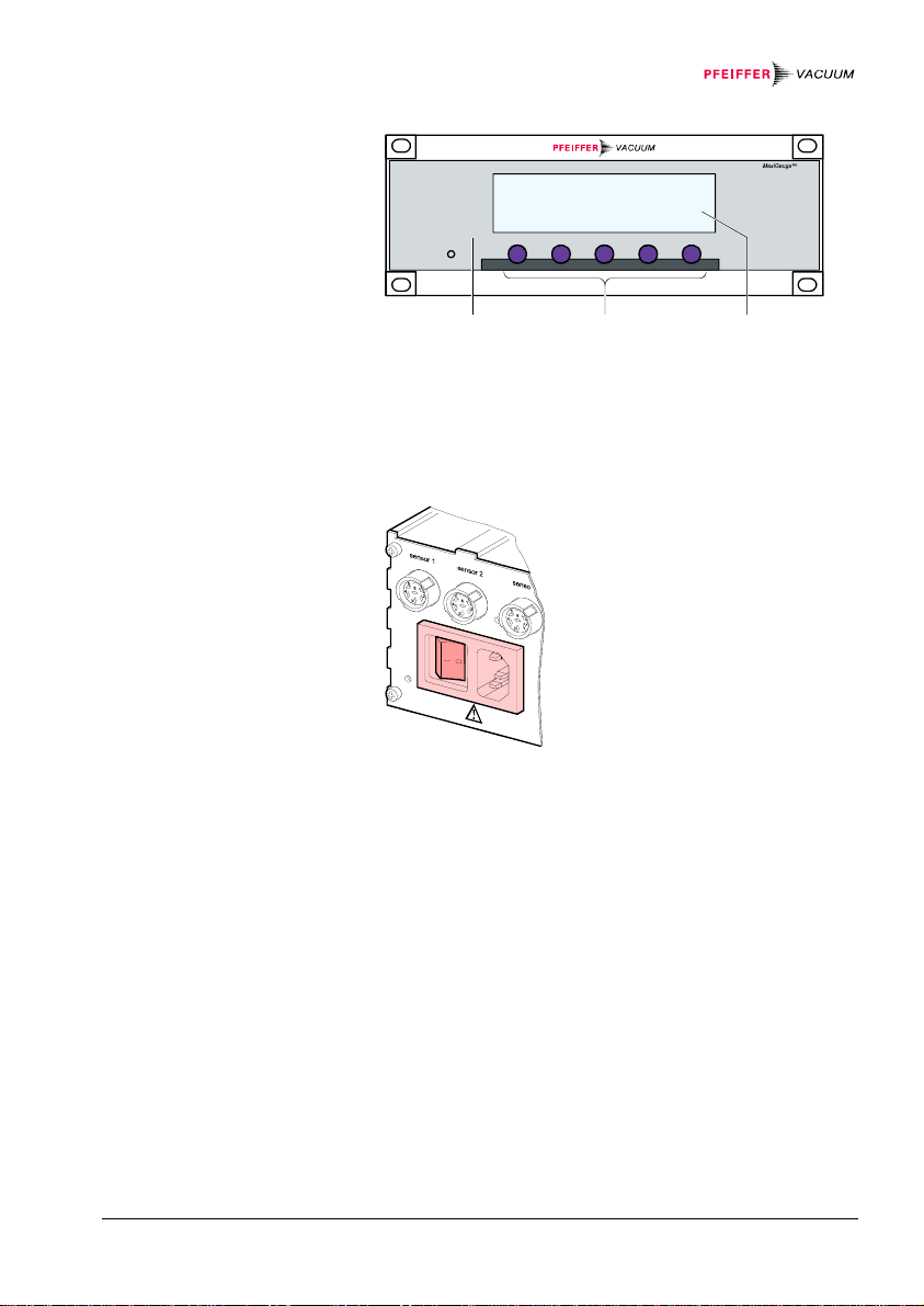
Figure 14:
Front panel
Figure 15:
Power switch
12 3
1 Mains power indicator (green LED): on / off
2 Display (LCD): Measured values and operation data
3 5 Softkeys (operating keys with varying functions)
BG 5186 BEN / C (2013-12) MaxiGauge.om Operating elements and modes 25
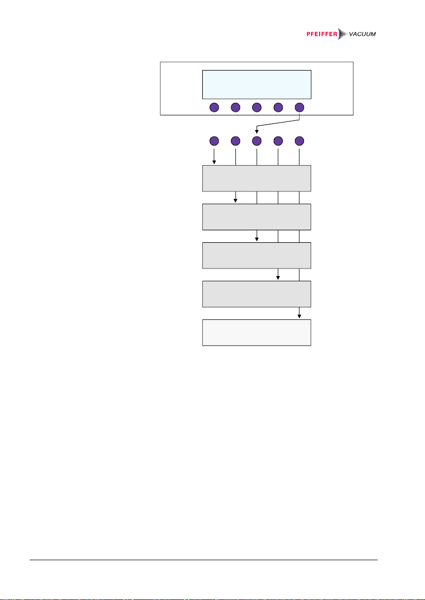
Figure 16:
Operating modes
Measurement Mode
Setpoint Mode
General Parameter Mode
Sensor Parameter Mode
Sensor Control Mode
Test Mode
26 Operating elements and modes
BG 5186 BEN / C (2013-12) MaxiGauge.om

5.2 Operating Modes
(Overview)
«Measurement»
«Setpoint»
«General Parameter»
«Sensor Parameter»
«Sensor Control»
«Test»
In «Measurement» mode, the TPG 256 A displays either
the measured value of one single gauge at a time in big
characters or the measured values of all gauges
simultaneously in small characters (→ 28, 40).
In «Setpoint» mode, a you can assign a switching function to a measurement point and define the corresponding setpoints (→ 30, 42).
In «General Parameter» mode, you can define the system parameters (for all connected gauges together)
(→ 31, 48).
In «Sensor Parameter» mode, you can define the relevant parameters for each gauge (→ 32, 58).
In «Sensor Control» mode, you can define how an individual gauge is switched on / off (→ 33, 69).
The «Test» mode is used for diagnostic and service purposes (troubleshooting). Special knowledge and skills
are necessary for this work (→ 34, 109).
BG 5186 BEN / C (2013-12) MaxiGauge.om Operating elements and modes 27
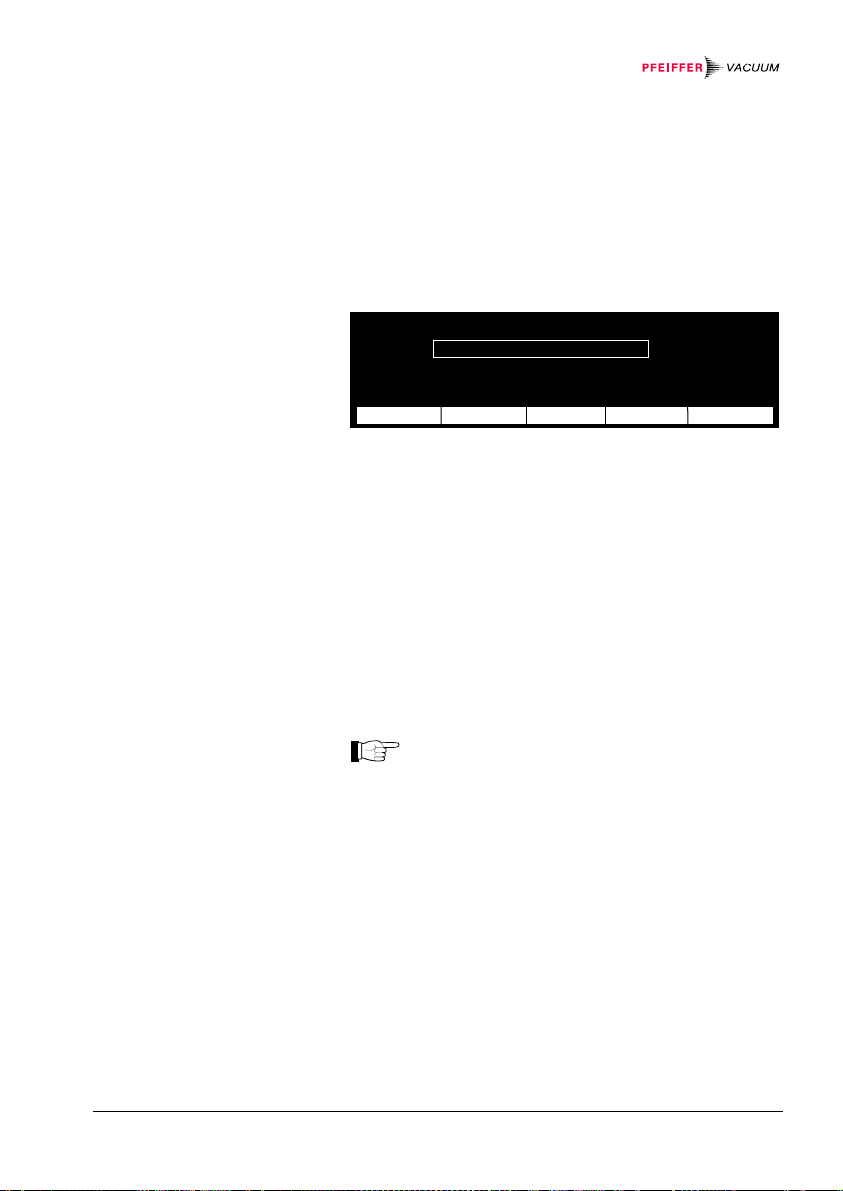
5.2.1 «Measurement»
S
All
Mode
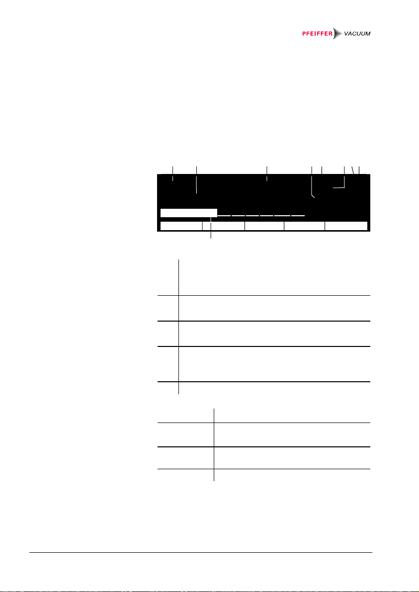
Figure 17:
«Single» display
Display
Softkeys
If the MaxiGauge is operated with linear gauges
(CMR 261 … 375, APR 250 … 267), negative pressures
may be indicated.
Possible causes:
• negative drift
• offset correction activated with positive offset
³´μ ³´μ Ø´Ù ³´μ Ø´Ù offset A¡
óÅ ¸ ÆÚ Â ÆÚ cal B¢
ÆÇÈ » õÝ ×ºÕ õÝ C£
ÉÊË CH 2 Ó½¾ Û ¼½¾ ß Û mbar D¤
E¥
ª£ F¦
ª¢
ensor
Mode
Measurement point selected (from 1 ... 6)
Name of measurement point, 4 characters, userdefinable (→ 68)
Measured value or status (→ 35)
Unit of measurement (→ 49)
Offset correction activated (→ 60)
Calibration factor ≠ 1.00 (→ 65)
Designation of the switching function (A ... F)
(→ 42)
Controlling source (from 1 ... 6) (→ 43)
Bargraph (analog measured value) (→ 51)
Sensor Selection of measurement point
Sen-on *
Sen-off *
All Displaying the measured values of all
)
Turning the gauge on
)
Turning the gauge off
measurement points
Mode Activating the operating mode selection
*) This parameter is not available for all gauge types
(→ Validity table 108).
28 Operating elements and modes
BG 5186 BEN / C (2013-12) MaxiGauge.om
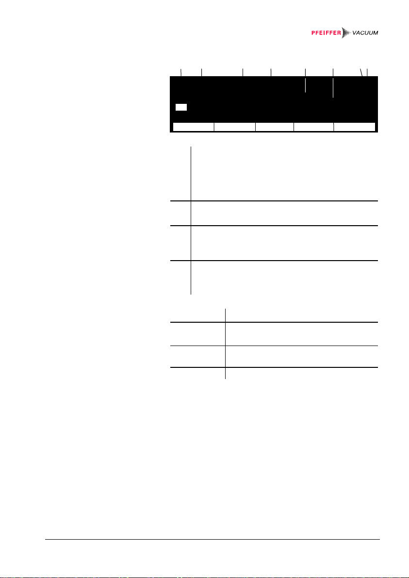
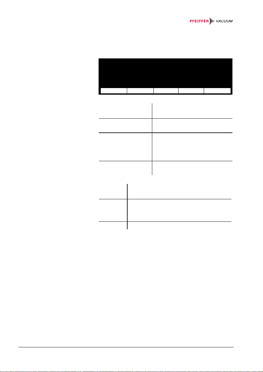
Figure 18:
S
5
«All» display
Display
Softkeys
1 CH 1 2.9E-02 mbar A¡
2 CH 2 244.5 mbar B¢
3 CH 3 1.3E-08 mbar cal C£
4 CH 4 9.9E-08 mbar degas D¤
CH 5 0.00530 mbar offset E¥
6 CH 6 no Sensor F¦
ensor Sen-off Single Mode
All measurement points (1 ... 6)
The selected measurement point is represented
inversely
Name of measurement point, 4 characters, userdefinable (→ 68)
Measured values or status (→ 35)
Unit of measurement (→ 49)
Calibration factor ≠ 1.00 (→ 65)
Sensor 4: Degas activated (→ 63)
Sensor 5: Offset correction activated (→ 60)
Designation of the switching function (A ... F)
(→ 42)
Controlling source (from 1 ... 6) (→ 43)
Sensor
Sen-on *
Sen-off *
Single Displaying the measured value of an
Selection of measurement point
)
Turning the gauge on
)
Turning the gauge off
individual measurement point
Mode Activating the operating mode selection
*) This parameter is not available for all gauge types
(→ Validity table 108).
BG 5186 BEN / C (2013-12) MaxiGauge.om Operating elements and modes 29
5.2.2 «Setpoint»
Mode
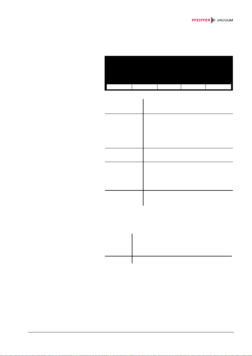
Figure 19:
«Setpoint» display
Display
Softkeys
³´μ Control Sensor 3
 Setpoint high 5.00E-05 mbar
 Setpoint low 2.00E-05 mbar
¼½¾ UR-Control off
Relay next ®¯ ¬− Return
C Switching function selected
(from A ... F)
Control Sensor Controlling source (1 ... 6) of
switching function C (→ 43)
Setpoint high Upper threshold of switching
function C (→ 44)
Setpoint low Lower threshold of switching
function C (→ 44)
UR-Control *
)
Behavior of switching function C
in case of underrange (→ 46)
Relay Selection of switching function (from
A ... F)
next Parameter selection
®¯ Increasing the value
¬− Decreasing the value
Return Returning to the «Measurement» mode
*) This parameter is not available for all gauge types
(→ Validity table 108).
30 Operating elements and modes
BG 5186 BEN / C (2013-12) MaxiGauge.om
5.2.3 «General Parameter» Mode
Figure 20:
«General Parameter» display
Display
Softkeys
Key-lock off Interface RS-485
Baudrate 19200
Unit mbar Address 0
Digits 3
Bargraph 1 Decade Screensave 5 h
Default set Contrast 10
next ®¯ ¬− Return
Key-lock Parameter input lock enabled or dis-
abled (→ 48)
Unit *)
Digits Resolution of the measured value dis-
Pressure unit (→ 49)
play (logarithmic gauges only)
(→ 50)
Bargraph
Default Loading the standard values of the
Bargraph (→ 51)
parameters (→ 52)
Interface
Baudrate
Address **) Software address of the interface
Type of the serial interface (→ 53)
Baud rate of the interface (→ 54)
(→ 55)
Screensave
Contrast
*) The pressure units depend on the gauges used
(→ Validity table 36).
)
**
This parameter is available for the RS485 interface only.
next Parameter selection
Screensave (→ 56)
Contrast of the display (→ 57)
®¯ Increasing the value
¬− Decreasing the value
Return Returning to the «Measurement» mode
BG 5186 BEN / C (2013-12) MaxiGauge.om Operating elements and modes 31

5.2.4 «Sensor Para-
S
meter» Mode
Figure 21:
«Sensor Parameter» display
Display
Softkeys
³´μ Type APR/CMR 1000 mbar
óÅ Offset on 157.6 mbar
ÆÇÈ CAL-Factor 1.010
ÉÊË Filter standard
Name CH 2
ensor next ®¯ ¬− Return
2 Measurement point selected (from
1 ... 6)
)
Type *
Family of gauge **) connected /
type of gauge connected (→ 59)
)
Offset ***
or
Degas ***
)
or
Range-Ext ***
Cal-Factor Calibration factor selected for
Activation of offset correction
(→ 60)
Activation of degas (→ 63)
)
Pirani range extension
measurement point 2 (→ 65)
Filter Measured value filter selected for
measurement point 2 (→ 66)
Name User-definable name for measure-
ment point (up to 4 characters)
(→ 68)
*) Depending on the type of gauge identified, the measurement
range may need to be indicated.
)
**
The family of linear including ACR gauges are displayed with
APR/CMR.
)
***
This parameter is not available for all gauge types
(→ Validity table 108).
Sensor Selection of measurement point
next Parameter selection
®¯ Increasing the value
¬− Decreasing the value
Return Returning to the «Measurement» mode
32 Operating elements and modes
BG 5186 BEN / C (2013-12) MaxiGauge.om

5.2.5 «Sensor Control»
S
Mode
Figure 22:
«Sensor Control» display
Display
Softkeys
Ò´Ô Control Hotstart
ñìí ON Power on
îïð OFF Selfcontrol
Ó½¾ OFF Threshold 9.00E-5 mbar
ensor next Return
5 Measurement point selected
(from 1 ... 6)
Control *
)
Controlling source of measure-
ment point 5 (→ 71)
ON Measurement point 5 is activa-
ted when the unit is switched on
OFF Selfcontrol Switching-off mode of measure-
ment point 5
OFF Threshold Switching-off threshold of
measurement point 5 in selfmonitoring mode
*) This parameter is not available for all gauge types
(→ Validity table 108).
Sensor Selection of measurement point
next Parameter selection
®¯ Increasing the value
¬− Decreasing the value
Return Returning to the «Measurement» mode
BG 5186 BEN / C (2013-12) MaxiGauge.om Operating elements and modes 33

5.2.6 «Test» Mode
Figure 23:
«Test» display
Display
Softkeys
Program BG509730-K
RAM A/D
EPROM I/O
EEPROM Interface
Display WDT-Ctrl auto
next Start Return
Program
RAM
EPROM
EEPROM
Display
A/D
I/O
Interface
WDT-Ctrl
Firmware version (→ 109)
RAM self-test (→ 110)
EPROM self-test (→ 110)
EEPROM self-test (→ 110)
Display self-test (→ 111)
Test analog/digital converter (→ 111)
Relay test (→ 111)
Test serial interface (→ 112)
Watchdog control (→ 112)
next Parameter selection
Start Starting a test sequence
Return Returning to the «Measurement» mode
The «Test» mode is only available if a key was
pressed while the unit was switched on.
34 Operating elements and modes
BG 5186 BEN / C (2013-12) MaxiGauge.om

6 Display Formats and Pressure Units
S
All
6.1 Display Formats
Figure 24:
Exponential representation
Figure 25:
Display formats
Both, exponential and floating point formats are used.
The format is changed over automatically. Pressures
indicated in «Pa» are displayed in exponential format
only.
³´μ óÐ ¿À ³´μ Ò´Ô ³´μ ¿À A¡
óÅ ÆÑÁ ÃÁ Â Â Â Â ÃÁ cal B¢
ÆÇÈ ÉÊÎ Á ×ºÕ ÷º ÌÏ Â Â Á C£
ÉÊË CH 2 Áß ÍÎ ¼½¾ æ½Ë ¼½¾ ÍÎ mbar D¤
E¥
+0.2 «¡
ª0 F¦
ensor
50 bar
Logarithmic
gauges
Mode
Linear
gauges
1000 mbar
Floating point format Floating point format
e.g. 4.3 e.g. 4.3
1 mbar
(or 1 Torr)
-11
10
mbar
e.g. 4.16E-01
Exponential format
BG 5186 BEN / C (2013-12) MaxiGauge.om Display formats / Pressure units 35
6.2 Pressure Units
S
2
6.3 Cursor
Figure 26:
Cursor (inverse representation
of parameter value)
Figure 27:
Cursor (inverse representation
of gauge / switching function)
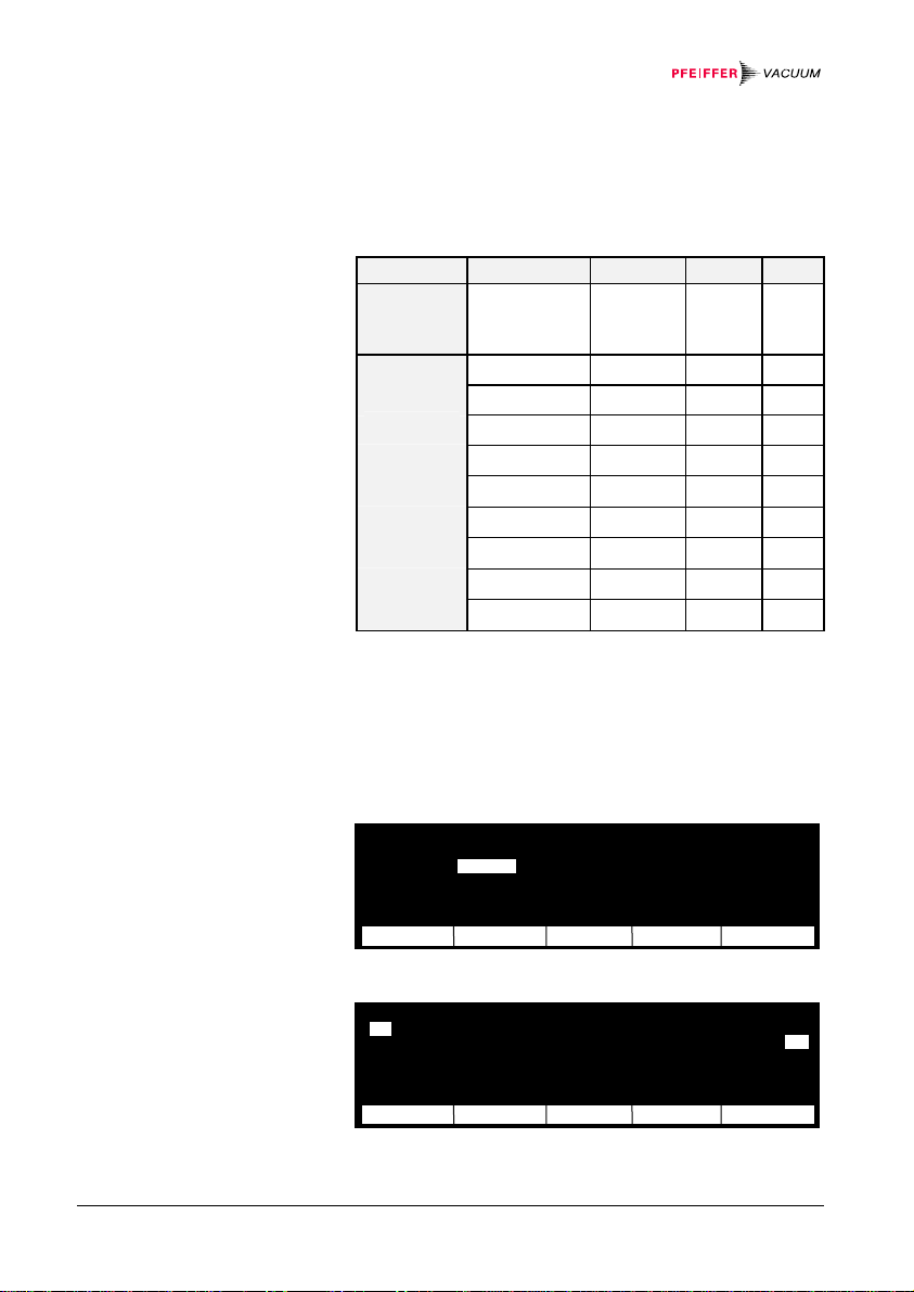
Whether a particular pressure unit can be displayed or
not depends on the gauge used. The TPG 256 A allows
the selection of a specific pressure unit only if it is
possible to display the pressure in that unit over the
whole measurement range.
Gauge Range*) mbar/bar Torr Pa
Logarithmic 10
-11
…
mbar
1000 mbar
0.1 mbar
1 mbar
10 mbar
100 mbar
Linear 1000 mbar
2 bar
5 bar
10 bar
50 bar
Conversion of pressure units (→ 109)
*) Full scale value for linear gauges
The cursor points out a selected parameter (value), a
gauge or a switching function status «on» by representing it inversely.
Key-lock off Interface RS-485
Baudrate 19200
Unit Address 0
Digits 3
Bargraph 1 Decade Screensave 5 h
Default set Contrast 10
next ®¯ ¬− Return
mbar
1 CH 1 2.9E-02 mbar A¡
CH 2 4.16E-01 mbar B¢
3 CH 3 1.3E-08 mbar cal
4 CH 4 9.9E-11 mbar D¤
5 CH 5 0.0053 mbar offset E¥
6 CH 6 no Sensor F¦
ensor Sen-off Single Mode
C£
36 Display formats / Pressure units
BG 5186 BEN / C (2013-12) MaxiGauge.om

7 Operation
7.1 Personnel
7.2 Switching the Unit
On and Off
Power ON
Figure 28:
Power switch
Skilled personnel
The unit may only be operated by skilled and trained
persons that fully understand the possible hazards related to the corresponding application.
Check that all cables and gauges have been correctly
installed and that the specifications listed in the technical
data have been met.
Turn the unit on with the power switch (or centrally via a
switched power distributor if the unit is rack mounted).
The power switch is located on the rear panel of the unit.
BG 5186 BEN / C (2013-12) MaxiGauge.om Operation 37

Figure 29:
Display after power ON
After power ON, the unit:
• automatically performs a self-test, and «TPG 256 A»
is displayed
• identifies the gauges connected
• activates parameters that were in effect before the
last power OFF
• switches to the «Measurement» mode for the measurement point selected before the last power OFF
• adapts the parameters if required (if other gauges
were previously connected)
Power OFF
• Turn the unit off with the power switch (or centrally via
a switched distributor if the unit is rack mounted).
Wait at least 10 seconds before turning the unit
on again in order for it to correctly initialize
itself.
38 Operation
BG 5186 BEN / C (2013-12) MaxiGauge.om

7.3 Selecting the
S
All
S
Operating Mode
Figure 30:
Selecting the operating mode
Returning from other
operating modes
In the superset«Measurement» mode, you can call a
menu of further operating modes by pressing the [Mode]
softkey
Select the desired mode by pressing the corresponding
softkey:
• [Setpoint] «Setpoint» mode
• [Gen-Par] «General Parameter» mode
• [Sen-Par] «Sensor Parameter» mode
• [Sen-Ctrl] «Sensor Control» mode
³´μ óÐ ¿À ³´μ Ò´Ô ³´μ ¿À A¡
óÅ ÆÑÁ ÃÁ Â Â Â Â ÃÁ cal B¢
ÆÇÈ ÉÊÎ Á ×ºÕ ÷º ÌÏ Â Â Á C£
ÉÊË CH 2 Áß ÍÎ ¼½¾ æ½Ë ¼½¾ ÍÎ mbar D¤
E¥
«¡
ª0 F¦
ensor
ensor Gen-Par Sen-Par Sen-Ctrl Test
Mode
The «Test» mode can only be selected if a key was
pressed while the unit was switched on:
• [Test] «Test» mode
If you are in a lower mode, simply press the [Return]
softkey to return to the superset «Measurement» mode.
If you do not press any key for 1 minute, the display returns automatically to the «Measurement» mode.
BG 5186 BEN / C (2013-12) MaxiGauge.om Operation 39

7.4 «Measurement»
S
S
All
Mode
Figure 31:
«Single» display
Figure 32:
«All» display
7.4.1 Selecting the
Measurement Point
(
Sensor)
In the superset «Measurement» mode, the unit displays
the measured values. If you are in another (lower) mode
and do not press any key for 1 minute, the unit returns
automatically to the «Measurement» mode.
(→ Overview «Measurement» mode 28).
³´μ óÐ ¿À ³´μ Ò´Ô ³´μ ¿À A¡
óÅ ÆÑÁ ÃÁ Â Â Â Â ÃÁ cal B¢
ÆÇÈ ÉÊÎ Á ×ºÕ ÷º ÌÏ Â Â Á C£
ÉÊË CH 2 Áß ÍÎ ¼½¾ æ½Ë ¼½¾ ÍÎ mbar D¤
E¥
«1
ª0 F¦
ensor
1 CH 1 2.9E-02 mbar A¡
2
CH 2 4.16E-01 mbar B¢
3 CH 3 1.3E-08 mbar cal C£
4 CH 4 9.9E-11 mbar D¤
5 CH 5 0.0053 mbar offset E¥
6 CH 6 no Sensor F¦
ensor Sen-off Single Mode
Mode
• The measurement point is indicated as a number on
the left of the display.
• Select the next measurement point with the [
Sensor]
softkey (in «Single» measurement mode, the corresponding number is increased whereas in «All», the
selected measurement point is represented inversely). After the measurement point 6 the display
changes to measurement point 1.
40 Operation
BG 5186 BEN / C (2013-12) MaxiGauge.om

7.4.2 Switching the
Gauge On/Off
(
Sen-on/off)
7.4.3 Display of a Single
Gauge / All Gauges
(
Single/All)
• Press the [Sen-off] softkey to turn the selected
gauge off or the [
Sen-on] key to turn it on.
Caution
Turning a gauge on or off may affect the status of the
relays.
This parameter is not available for all gauge
types (→ Validity table 108).
• Press the [Single]/[All] softkey in order for the
unit to display either the measured value of one single gauge at a time or the measured values of all
gauges simultaneously (→ 40).
Status or error messages may be displayed
instead of measured values (→ Status messages 75, Error messages 77). After the
problem is remedied, the measured value is
again displayed correctly.
BG 5186 BEN / C (2013-12) MaxiGauge.om Operation 41
7.5 «Setpoint» Mode
Figure 33:
«Setpoint» display
7.5.1 Selecting the
Switching Function
(
Relay)
In «Setpoint» mode, you can assign a controlling source
to a switching function and define the upper and lower
thresholds. Additionally, you can select the behavior of
the switching function in the event of an underrange.
(→ Overview «Setpoint» mode 30).
³´μ Control Sensor 3
 Setpoint high 5.00E-05 mbar
 Setpoint low 2.00E-05 mbar
¼½¾ UR-Control off
Relay next ®¯ ¬− Return
The switching function is represented as a letter on the
left of the display.
Selecting another switching function:
• Press the [
switching function (
Relay] softkey to choose the desired
A ... F).
The modifications are automatically stored in non-volatile
memory.
42 Operation
BG 5186 BEN / C (2013-12) MaxiGauge.om

7.5.2 Assigning
S
All
Measurement
Points
(
Control Sensor)
Figure 34:
«Setpoint» display
«Measurement» display
The upper parameter line «Control Sensor» shows
which measurement point is assigned to a switching
function.
The corresponding measurement point has to be assigned to each switching function individually. In
«Measurement» mode, all assignments are displayed
simultaneously.
³´μ Control Sensor 3
 Setpoint high 5.00E-05 mbar
 Setpoint low 2.00E-05 mbar
¼½¾ UR-Control off
Relay next ®¯ ¬− Return
³´μ óÐ ¿À ³´μ Ò´Ô ³´μ ¿À A¡
óÅ ÆÑÁ ÃÁ Â Â Â Â ÃÁ cal B¢
ÆÇÈ ÉÊÎ Á ×ºÕ ÷º ÌÏ Â Â Á C£
ÉÊË CH 2 Áß ÍÎ ¼½¾ æ½Ë ¼½¾ ÍÎ mbar D¤
E¥
«¡
+0 F¦
ensor Sen-on
Mode
Assigning another measurement point:
• Select the «Setpoint» mode (if applicable) (→ 39)
• Press the [
Control Sensor» parameter
«
• Press the [
value «
• Press the [
next] softkey to select the
®¯]or [¬−] softkey to select a parameter
1 ... 6» (measurement points)
Return] softkey to return to the
«Measurement» mode
The modifications are automatically stored in non-volatile
memory.
BG 5186 BEN / C (2013-12) MaxiGauge.om Operation 43

7.5.3 Defining the
Threshold Values
(
Setpoint)
Figure 35:
«Setpoint» display
The upper and lower thresholds are defined in the second and third parameter line.
³´μ Control Sensor 3
 Setpoint high 5.00E-05 mbar
 Setpoint low 2.00E-05 mbar
¼½¾ UR-Control off
Relay next ®¯ ¬− Return
Defining the threshold values:
• Select the «Setpoint» mode (if applicable) (→ 39)
• Press the [
Setpoint high» parameter
«
• Press the [
next] softkey to select the
®¯] or [¬−] softkey to increase /decrease
the upper threshold value
• Press the [
«
Setpoint low» parameter
• Press the [
next] softkey to select the
®¯] or [¬−] softkey to increase / decrease
the lower threshold value
• Press the [
Return] softkey to return to the
«Measurement» mode
A threshold that is outside the measuring range
is adjusted in such a way that it corresponds to
the lower (upper) range limit.
We recommend setting the threshold ½ decade
above the lower or ½ below the upper threshold
limit.
If both thresholds are outside the measuring
range, they are adjusted analogously in such a
way that a minimum hysteresis is achieved.
For logarithmic gauges, threshold values are
displayed in logarithmic or floating point format,
whereas for linear gauges, they are displayed
in floating point format only (→ Display formats
35).
The modifications are automatically stored in non-volatile
memory.
44 Operation
BG 5186 BEN / C (2013-12) MaxiGauge.om
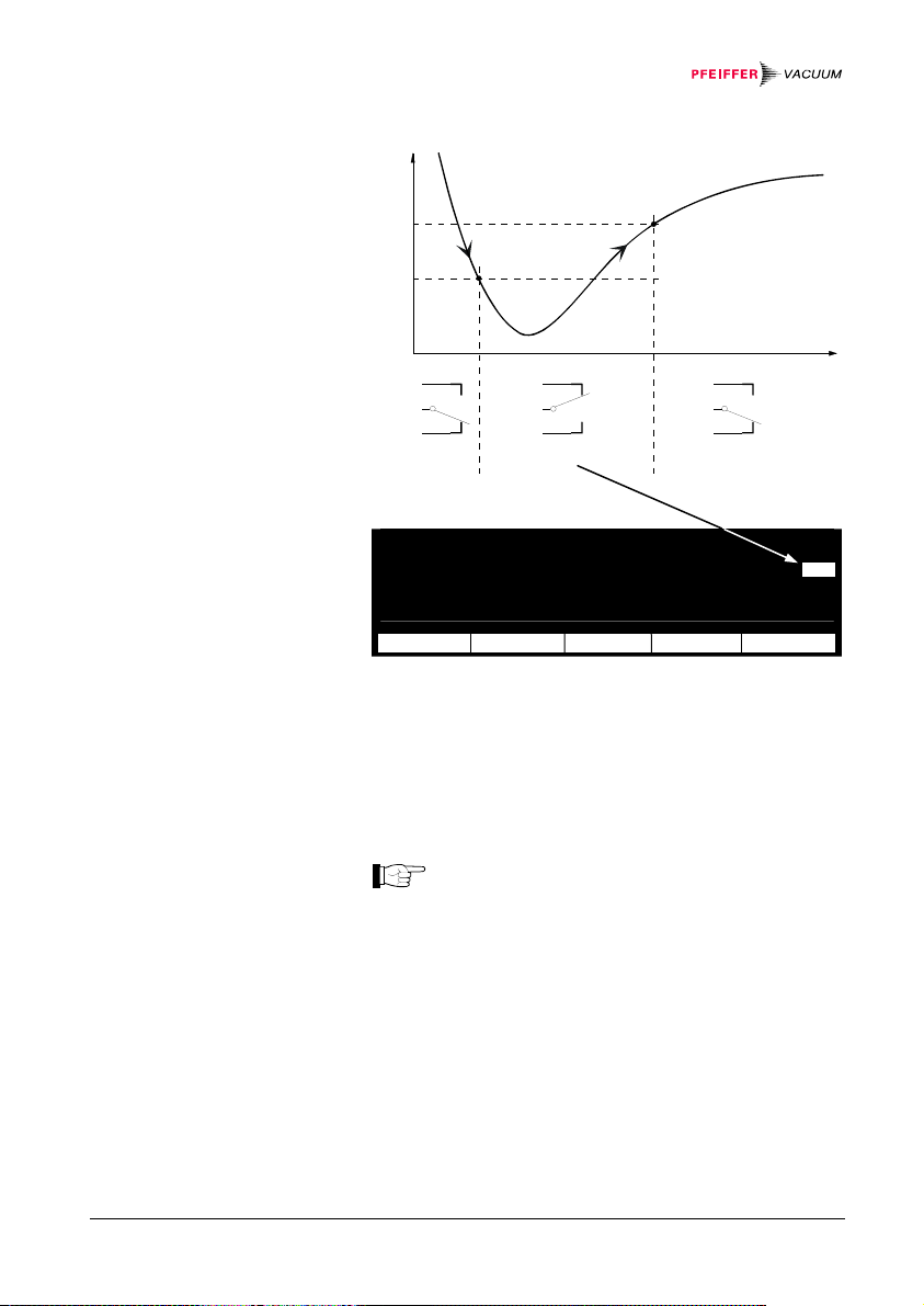
Figure 36:
S
C
Threshold values of a switching
function
Figure 37:
Inverse representation of the
selected switching function (
C3)
setpoint low
setpoint high
Pressure
u
l
a
v
d
e
r
u
s
a
e
M
Setpoint high
Setpoint low
Time
OnOff Off
Switching function
1 CH 1 2.9E-02 mbar A¡
2 CH 2 4.16E-01 mbar B¢
3 CH 3 1.3E-08 mbar cal
4 CH 4 9.9E-11 mbar D¤
5 CH 5 0.00530 mbar offset E¥
6 CH 6 no Sensor F¦
ensor Sen-off Single Mode
The setpoint low defines the pressure reading at
which the switching function is activated when the pressure is dropping.
setpoint high defines the pressure reading at
The
which the switching function is deactivated when the
pressure is rising.
If other gauge types were connected previ-
ously, the threshold may possibly have been
adapted automatically.
e
£
BG 5186 BEN / C (2013-12) MaxiGauge.om Operation 45

7.5.4 Underrange
Control
(
UR-Control)
Logarithmic gauges:
The minimum hysteresis between the upper
and lower threshold is at least 10% of the lower
threshold. This prevents an unstable state. If
you set the upper threshold lower than the
lower one, this minimum hysteresis is automatically applied.
Linear gauges:
The minimum hysteresis between the upper
and lower threshold is at least 1% of the
measurement range. This prevents an unstable
state. If you set the upper threshold lower then
the lower threshold, this minimum hysteresis is
automatically applied.
This parameter controls the behavior of the switching
function in the event of an underrange (→ Status messages 75).
An underrange may occur for one of the following reasons:
The pressure in the vacuum system is lower than the
lower limit of the measurement range
The gauge has not yet ignited
The discharge has failed
A fault has occurred
When the underrange control is enabled, an underrange
is interpreted as inadmissible measured value: The
switching function changes to «OFF».
When the underrange control is deactivated, the switching function remains «ON» in the event of an underrange.
The underrange control is deactivated by default.
46 Operation
BG 5186 BEN / C (2013-12) MaxiGauge.om
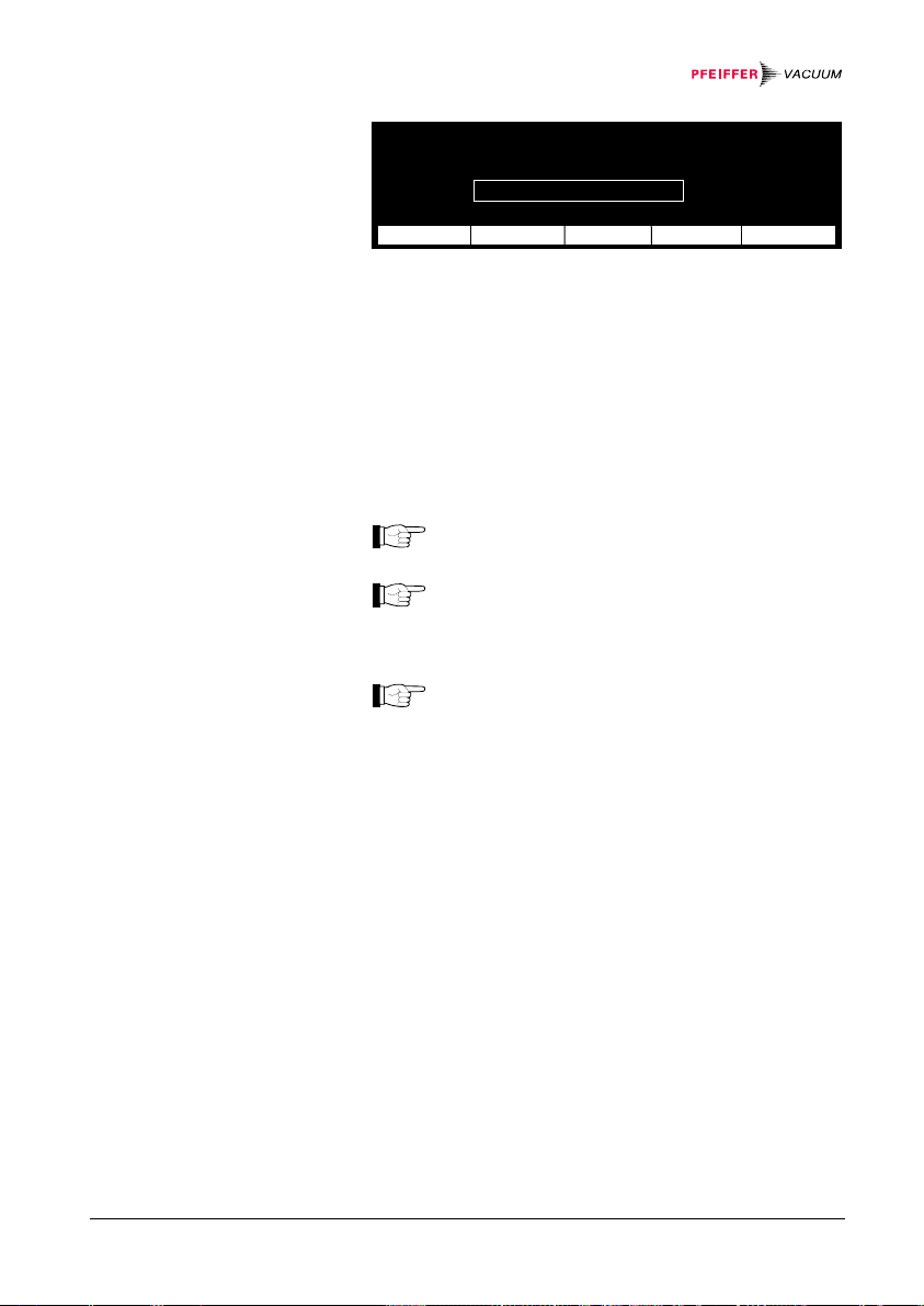
Figure 38:
«Setpoint» mode display
³´μ Control Sensor 3
 Setpoint high 5.00E-05 mbar
 Setpoint low 2.00E-05 mbar
¼½¾ UR-Control off
Relay next ®¯ ¬− Return
Enabling/disabling the underrange control:
• Select the «Setpoint» mode (if applicable) (→ 39)
• Press the [
UR-Control» parameter
«
• Press the [
(underrange control enabled) or «
next] softkey to select the
®¯] or [¬−] softkey to select «On»
Off» (underrange
control disabled (default))
• Press the [
Return] softkey to return to the
«Measurement» mode
This parameter is not available for all gauge
types (→ Validity table 108).
If the pressure in the vacuum chamber may be
lower than the lower limit of the measurement
range of the gauge it may be advantageous to
select «
off».
When «On» is selected, the switching function
evaluation is suppressed for approx. 10 seconds after the gauge has been turned on or an
underrange has occurred. The switching function remains «OFF» for this time.
The modifications are automatically stored in non-volatile
memory.
BG 5186 BEN / C (2013-12) MaxiGauge.om Operation 47

7.6 «General Parameter» Mode
Figure 39:
«General Parameter» display
7.6.1 Parameter Input
Lock (
Key-lock)
In «General Parameter» mode, you can define the system parameters for all connected gauges together.
(→ Overview «General Parameter» mode 31).
Key-lock off Interface RS-485
Baudrate 19200
Unit mbar Address 0
Digits 3
Bargraph 1 Decade Screensave 5 h
Default set Contrast 10
next ®¯ ¬− Return
The parameter input lock prevents inadvertent entries
and consequent malfunctions. When the parameter input
lock is enabled, only the «
Key-Lock» parameter for dis-
abling the input lock can be modified.
Turning the parameter input lock ON /OFF:
• Select the «General Parameter» mode (if applicable)
(→ 39)
• Press the [
next] softkey to select the «Key-lock»
parameter
• Press the [
lock ON) or «
• Press the [
®¯] or [¬−] softkey to select «On» (input
Off» (input lock OFF(default))
Return] softkey to return to the
«Measurement» mode
If the input lock is enabled and you press a
softkey to modify any other parameter than
«
Key-lock», «locked» is displayed instead
of the function of the softkey pressed.
The modifications are automatically stored in non-volatile
memory.
48 Operation
BG 5186 BEN / C (2013-12) MaxiGauge.om

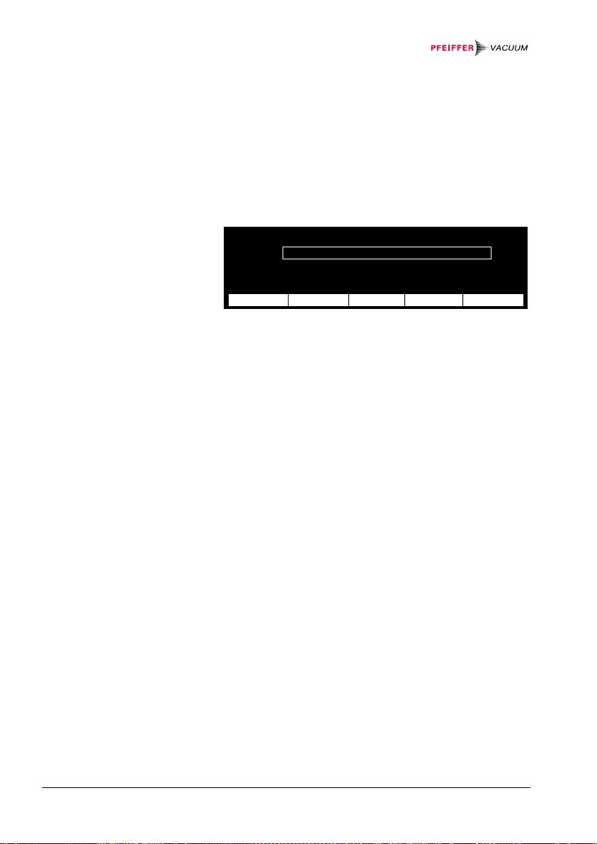
7.6.2 Selecting the
Pressure Unit
(
Unit)
Figure 40:
«General Parameter» display
The unit can display the following pressure units:
(milli)bar, Torr, and Pascal.
Key-lock off Interface RS-485
Baudrate 19200
Unit mbar Address 0
Digits 3
Bargraph 1 Decade Screensave 5 h
Default set Contrast 10
next ®¯ ¬− Return
Selecting the pressure unit:
• Select the «General Parameter» mode (if applicable)
(→ 39)
• Press the [
next] softkey to select the «Unit» pa-
rameter
• Press the [
Pa», or «mbar» (default) *
«
• Press the [
®¯] or [¬−] softkey to select «Torr»,
Return] softkey to return to the
)
«Measurement» mode
*) For linear gauges, a specific pressure unit can only be selected if
it is possible to display the measured pressure in that unit over
the whole measurement range of the gauge (→ table 36).
The modifications are automatically stored in non-volatile
memory.
BG 5186 BEN / C (2013-12) MaxiGauge.om Operation 49

7.6.3 Display Resolution
(
Digits)
Figure 41:
«General Parameter» display
For observing even fine measurement value fluctuations,
the display can be increased from 2 to 3 digits. The
measured value will thus have a finer resolution. (Only
effective for logarithmic gauges.)
Key-lock off Interface RS-485
Baudrate 19200
Unit mbar Address 0
Digits 3
Bargraph 1 Decade Screensave 5 h
Default set Contrast 10
next ®¯ ¬− Return
Defining the number of digits:
• Select the «General Parameter» mode (if applicable)
(→ 39)
• Press the [
next] softkey to select the «Digits» pa-
rameter
• Press the [
®¯] or [¬−] softkey to select «3» or «2»
(default)
• Press the [
Return] softkey to return to the
«Measurement» mode
When Range-Ext (→ 64) is on, the display resolution
of the PCR and TPR gauges in the pressure range
p<1.0E-4 mbar is reduced by one decimal digit.
The modifications are automatically stored in non-volatile
memory.
50 Operation
BG 5186 BEN / C (2013-12) MaxiGauge.om

7.6.4 Bargraph
(
Bargraph)
Figure 42:
«General Parameter» display
The bargraph allows quick assessment of the measured
value and visual observation of the measurement
changes (trend).
Key-lock off Interface RS-485
Baudrate 19200
Unit mbar Address 0
Digits 3
Bargraph 1 Decade Screensave 5 h
Default set Contrast 10
next ®¯ ¬− Return
Adjusting the bargraph:
• Select the «General Parameter» mode (if applicable)
(→ 39)
• Press the [
next] softkey to select the «Bargraph»
parameter
• Press the [
(bargraph deactivated), «
measurement range), or «
®¯] or [¬−] softkey to select «Off»
Sen-Range» (bar range =
1 Decade» (bar = meas-
urement value exponent (default))
• Press the [
Return] softkey to return to the
«Measurement» mode
The modifications are automatically stored in non-volatile
memory.
BG 5186 BEN / C (2013-12) MaxiGauge.om Operation 51

7.6.5 Restoring Default
Values (
Figure 43:
«General Parameter» display
Default)
This parameter allows to restore all user defined / modified parameters to the factory setting.
Key-lock off Interface RS-485
Baudrate 19200
Unit mbar Address 0
Digits 3
Bargraph 1 Decade Screensave 5 h
Default set Contrast 10
next °± set ±² Return
Restoring the default parameters:
• Select the «General Parameter» mode (if applicable)
(→ 39)
• Press the [
next] to select the «Default set» pa-
rameter
The [
®¯] and [¬−] softkeys are represented as one sin-
gle symbol prompting the user to press them simultane-
°± set ±²].
ously: [
• Press both softkeys simultaneously to restore the
default values
• Press the [
Return] softkey to return to the
«Measurement» mode
Caution
Restoring the default values cannot be reversed!
The modifications are automatically stored in non-volatile
memory.
52 Operation
BG 5186 BEN / C (2013-12) MaxiGauge.om

7.6.6 Defining an
Interface
(
Interface)
Figure 44:
«General Parameter» display
The serial interfaces are used for external control of the
unit as well as for transfer of measured data and modification of parameters (→ 13). The desired interface is
defined with the following parameter:
Key-lock off Interface RS-485
Baudrate 19200
Unit mbar Address 0
Digits 3
Bargraph 1 Decade Screensave 5 h
Default set Contrast 10
next ®¯ ¬− Return
Defining the interface:
• Select the «General Parameter» mode (if applicable)
(→ 39)
• Press the [
next] softkey to select the «Interface»
parameter
• Press the [
RS-485» (serial interface RS485, isolated),
«
«
RS-422I» (serial interface RS422C, isolated),
RS-422» (serial interface RS422C, not isolated),
«
RS-232» (serial interface RS232C, not isolated
«
®¯] or [¬−] softkey to select among
(default))
• Press the [
Return] softkey to return to the
«Measurement» mode
Check whether the unit is equipped with all
interfaces listed above (→ 2, 12).
The modifications are automatically stored in non-volatile
memory.
Further information → 80.
BG 5186 BEN / C (2013-12) MaxiGauge.om Operation 53

7.6.7 Defining the Baud
Rate (
Baudrate)
Figure 45:
«General Parameter» display
This parameter allows to set the baud rate for the serial
interface defined as «
Key-lock off Interface RS-485
Baudrate 19200
Unit mbar Address 0
Digits 3
Bargraph 1 Decade Screensave 5 h
Default set Contrast 10
next ®¯ ¬− Return
Interface» parameter value.
Setting the baud rate:
• Select the «General Parameter» mode (if applicable)
(→ 39)
• Press the [
next] softkey to select the «Baudrate»
parameter
• Press the [
(baud), «
(baud), «
®¯] or [¬−] softkey to select among «300»
1200» (baud), «2400» (baud), «4800»
9600» (baud (default)), and «19200»
(baud)
• Press the [
Return] softkey to return to the
«Measurement» mode
The modifications are automatically stored in non-volatile
memory.
Further information → 80.
54 Operation
BG 5186 BEN / C (2013-12) MaxiGauge.om

7.6.8 Defining the Node
Address
(
Address)
Figure 46:
«General Parameter» display
The RS485 interface allows to set up a network of max.
32 display units per interface. The node (or device) address can be set between 0 and 31.
Key-lock off Interface RS-485
Baudrate 19200
Unit mbar Address 0
Digits 3
Bargraph 1 Decade Screensave 5 h
Default set Contrast 10
next ®¯ ¬− Return
Defining the node address:
• Select the «General Parameter» mode (if applicable)
(→ 39)
• Press the [
next] softkey to select the «Address»
parameter
• Press the [
value «
• Press the [
®¯] or [¬−] softkey to select a parameter
0 ... 31» (node address) (default = 0)
Return] softkey to return to the
«Measurement» mode
This parameter is only available for the RS485
interface.
The modifications are automatically stored in non-volatile
memory.
Further information → 80.
BG 5186 BEN / C (2013-12) MaxiGauge.om Operation 55

7.6.9 Screensave
(
Screensave)
Figure 47:
«General Parameter» display
In order for the life of the CFL lamp to be prolonged
(half-life period approx. 20'000 hours), the backlighting
of the LC display can be switched off automatically after
an adjustable delay of 1 ... 99 hours while the LCD remains on.
Key-lock off Interface RS-485
Baudrate 19200
Unit mbar Address 0
Digits 3
Bargraph 1 Decade Screensave 5 h
Default set Contrast 10
next ®¯ ¬− Return
Adjusting the screensave function:
• Select the «General Parameter» mode (if applicable)
(→ 39)
• Press the [
Screensave» parameter
«
• Press the [
1 ... 99» (number of hours after which the back-
«
next] softkey to select the
®¯] or [¬−] softkey to select «Off» or
lighting of the LCD is to be switched off after a key
has been pressed) (Off = screensave deactivated
(default))
• Press the [
Return] softkey to return to the
«Measurement» mode
Press any softkey to reactivate the background
lighting. While the display is dark, all control or
selection functions of the softkeys are disabled.
The modifications are automatically stored in non-volatile
memory.
56 Operation
BG 5186 BEN / C (2013-12) MaxiGauge.om

7.6.10 Display Contrast
(
Contrast)
Figure 48:
«General Parameter» display
This parameter allows to set the contrast of the LC display within a numeric range of 0 ... 20 according to your
individual requirements, such as ambient conditions and
viewing angle.
Key-lock off Interface RS-485
Baudrate 19200
Unit mbar Address 0
Digits 3
Bargraph 1 Decade Screensave 5 h
Default set Contrast 10
next ®¯ ¬− Return
Setting the display contrast:
• Select the «General Parameter» mode (if applicable)
(→ 39)
• Press the [
next] softkey to select the «Contrast»
parameter
• Press the [
value «
®¯] or [¬−] softkey to select a parameter
0 ... 20» (minimum contrast ... maximum con-
trast) (default = 10)
• Press the [
Return] softkey to return to the
«Measurement» mode
The modifications are automatically stored in non-volatile
memory.
BG 5186 BEN / C (2013-12) MaxiGauge.om Operation 57

7.7 «Sensor Para-
S
meter» Mode
Figure 49:
«Sensor Parameter» display
7.7.1 Selecting a
Measurement Point
(
Sensor)
In «Sensor Parameter» mode, you can define the parameters relevant for each measurement point.
(→ Overview «Sensor Parameter» mode 32).
³´μ Type APR/CMR 1000 mbar
óÅ Offset on 157.6 mbar
ÆÇÈ CAL-Factor 1.010
ÉÊË Filter standard
Name CH 2
ensor next ®¯ ¬− Return
The measurement point to which the displayed parameters apply is shown as a big figure (1 ... 6) on the left
of the display.
• Select the «Sensor Parameter» mode (if applicable)
(→ 39)
• Press the [
urement point (from
Sensor] softkey to select the next meas-
1 ... 6).
58 Operation
BG 5186 BEN / C (2013-12) MaxiGauge.om

7.7.2 Gauge Identifi-
S
cation (
Figure 50:
«Sensor Parameter» display
Type)
The TPG 256 A automatically identifies any connected
Pfeiffer Vacuum gauges. For linear gauges, a
measurement range is displayed additionally as parameter value *
)
behind the gauge type **). This parameter value has to be adjusted according to the connected gauge type.
*) This parameter is not available for all gauge types
(→ Validity table 108).
)
**
The family of linear gauges are displayed with APR/CMR.
³´μ Type APR/CMR 1000 mbar
óÅ Offset on 157.6 mbar
ÆÇÈ CAL-Factor 1.010
ÉÊË Filter standard
Name CH 2
ensor next ®¯ ¬− Return
Adjusting the measurement range:
• Select the «Sensor Parameter» mode (if applicable)
(→ 39)
• Press the [
next] softkey to select the «APR/CMR»
(linear gauge types identified) parameter
• Press the [
0.1 mbar», «1 mbar», «10 mbar», «100 mbar»,
«
1000 mbar» (default), «2 bar», «5 bar», «10
«
bar
• Press the [
®¯] or [¬−] softkey to select among
», and «50 bar»
Return] softkey to return to the
«Measurement» mode
The modifications are automatically stored in non-volatile
memory.
BG 5186 BEN / C (2013-12) MaxiGauge.om Operation 59
7.7.3 Offset Function
S
(
Offset) (zeroing)
Figure 51:
«Sensor Parameter» display
Activating /
deactivating the offset
function
Zero adjustment
The offset function allows the zero of linear gauges to be
aligned to the currently measured value (uncorrected
outputsignal of the gauge) within a range of -5 ... +110%
of the Full Scale setting. It affects the:
display
switching functions (threshold value display)
analog outputs of the unit
serial interfaces
³´μ Type APR/CMR 1000 mbar
óÅ Offset on 157.6 mbar
ÆÇÈ CAL-Factor 1.010
ÉÊË Filter standard
Name CH 2
ensor next ®¯ ¬− Return
• Select the «Sensor Parameter» mode (if applicable)
(→ 39)
• Press the [
next] softkey to select the «Offset» pa-
rameter
• Press the [
correction activated) or «
®¯] or [¬−] softkey to select «on», (offset
off» (offset correction de-
activated) (default) (the previously saved offset value
displayed at the right hand side of the «
on»/«off»
parameter value)
This function can be used for two different purposes:
There are two methods for adjusting the zero of a linear
gauge. Note, however, that the actual pressure must be
lower than the lower limit of the measurement range of
the gauge:
− Set the zero by adjusting the „ZERO“ potentiometer
of the gauge (
→ [16] … [18])
− With the offset function of the measurement and
control unit set the current pressure reading to zero
60 Operation
BG 5186 BEN / C (2013-12) MaxiGauge.om

Zeroing at any
pressure
Procedure for the second method:
• at a pressure lower than the lower limit of the measurement range of the gauge, activate the offset
function («
• press the [
saved offset value (at the right hand side of «
the displays of the [
Actual] and [Zero]
[
• press the [
on»)
next] softkey to select the previously
on»);
®¯] and [¬−] softkeys change to
Actual] softkey to accept the currently
measured value (zero deviation) as new offset value.
(If you like to set the offset value to zero, press the
[
Zero] softkey).
• press the [
Return] softkey to return to the
«Measurement» mode
The advantage of the second method is that no direct
access to the potentiometer of the gauge is required.
The pressure reading of the measurement and control
unit can be set to zero at any pressure within the measurement range. All subsequent readings will then be
relative to that pressure and may therefore be positive or
negative. This method allows for monitoring of pressure
variations during a process.
The procedure is the same as for the second method.
This parameter is not available for all gauge
types (→ Validity table 108).
The modifications are automatically stored in non-volatile
memory.
BG 5186 BEN / C (2013-12) MaxiGauge.om Operation 61

Example:
S
When the offset function is activated, the stored offset
value is subtracted from the currently measured value.
³´μ Type APR/CMR 1000 mbar
óÅ Offset on 10.3 mbar
ÆÇÈ CAL-Factor 1.000
ÉÊË Filter standard
Name CH 2
ensor next ®¯ ¬− Return
Currently
measured
value
10.3 10.3 0 10.3
17.4 10.3 7.1 17.4
7.4 10.3 -2.9 7.4
Stored
offset value
Display with
offset
activated:
offset
Display with
offset
deactivated:
When the zero of the gauge is adjusted with the
"ZERO" potentiometer, the offset function must
be deactivated.
The offset values are preserved when the unit
is switched off.
62 Operation
BG 5186 BEN / C (2013-12) MaxiGauge.om
7.7.4 Activating the
S
Degas Routine
(
Degas)
Figure 52:
«Sensor Parameter» display
Contamination of the electrode system of the Compact
Fullrange™ BA Gauge (PBR 260) can cause instabilities
of the measured values.
The degassing routine is used for cleaning the electrode
system by heating the electron collector grid to approx.
700 °C by electron bombardment.
It normally takes 3 minutes but it can be aborted at any
stage.
óÐ Type PBR
ÆÑÁ Degas on
ÉÊÎ CAL-Factor 1.010
Á Filter standard
Name CH 4
ensor next ®¯ ¬− Return
To activate or abort the degassing routine:
• Select the «Sensor Parameter» mode (if applicable)
→ 39)
(
• Press the [
next] softkey to select the «Degas» pa-
rameter
• Press the [
activated) or «
• Press the [
®¯] or [¬−] softkey to select «on», (Degas
off» (Degas deactivated) *
Return] softkey to return to the
)
(default)
«Measurement» mode
*) After conclusion of the ≈3 min. degassing routine, the «Degas»
parameter automatically goes back to «off» (default).
• The Degas function is only available for
sensor connectors 4 to 6.
• The degassing routine can only be
started («
on») when the corresponding
gauge is turned on.
• When Degas = «
message «
on», the status
Degas» is displayed in
«Measurement» mode.
BG 5186 BEN / C (2013-12) MaxiGauge.om Operation 63

7.7.5 Pirani Range
S
Extension
(
Range-Ext)
Figure 53:
«Sensor Parameter» display
Activate/deactivate
Pirani range
extension
The display and setpoint adjustment range of the PCR
und TPR gauges can be extended.
óÐ Type PCR
ÆÑÁ Range-Ext off
ÉÊÎ CAL-Factor 1.010
Á Filter standard
Name CH 4
ensor next ®¯ ¬− Return
• Select the «Sensor Parameter» mode (if applicable)
(→ 39)
• Press the [
next] softkey to select the «Range-Ext»
parameter
• Press the [
range extension activated) or «
®¯] or [¬−]softkey to select «on», (Pirani
off» (Pirani range
extension deactivated) (default)
• Press the [
Return] softkey to return to the
«Measurement» mode
64 Operation
BG 5186 BEN / C (2013-12) MaxiGauge.om

7.7.6 Setting the
S
Calibration Factor
(
Cal-Factor)
Figure 54:
«Sensor Parameter» display
For logarithmic gauges
For linear gauges
The calibration function allows to adjust the measured
value of a gauge. It is predominantly used for correcting
the measured values of logarithmic gauges for gases
other than N
linear gauges. The calibration factor affects the:
display *
switching functions (threshold value display) *
analog outputs of the unit
serial interfaces *
*) For IMR 260, IMR 265, and PBR 260 (p≤10–1 mbar) in the hot
cathode measurement range only.
³´μ Type TPR
óÅ
ÆÇÈ CAL-Factor 1.010
ÉÊË Filter standard
Name CH 2
ensor next ®¯ ¬− Return
and for correcting the full scale values of
2
)
)
)
Each of the six gauges can be calibrated in the following
way:
• Select the «Sensor Parameter» mode (if applicable)
(→ 39)
• Press the [
«
Cal-Factor» in the following way:
next] softkey to select the
• Press the [®¯] or [¬−] softkey to adjust the parameter
value «
0.10 ... 1.00 (default) ... 9.99» (the value
increases or decreases by
0.01)
• If you hold down the softkey continually, the step size
changes automatically to
• Press the [
«Measurement» mode
Return] softkey to return to the
0.1
• Press the [®¯] or [¬−] softkey to adjust the parameter
value «
0.500 ... 1.000 (default) ... 2.000» (the
value increases or decreases by
0.001)
• If you hold down the softkey continually, the step size
changes automatically to
• Press the [
Return] softkey to return to the
0.01
«Measurement» mode
The modifications are automatically stored in non-volatile
memory.
BG 5186 BEN / C (2013-12) MaxiGauge.om Operation 65

7.7.7 Setting the
S
Measurement
Value Filter
(
Filter)
Figure 55:
«Sensor Parameter» display
Standard Filter
Figure 56:
Measurement value filter
Standard
The measurement value filter allows better evaluation of
unstable or faulty measurement signals. It affects the:
display
switching functions (threshold value display)
analog outputs of the unit
serial interfaces
³´μ Type APR/CMR 1000 mbar
óÅ Offset on 157.6 mbar
ÆÇÈ CAL-Factor 1.010
ÉÊË Filter standard
Name CH 2
ensor next ®¯ ¬− Return
For each of the six gauges, a filter can be set in the following way:
• Select the «Sensor Parameter» mode (if applicable)
(→ 39)
• Press the [
next] softkey to select the «Filter» pa-
rameter
• Press the [
fast», «slow» and «standard» (default) pa-
«
®¯] or [¬−] softkey to select among
rameter value (→ following explanations)
• Press the [
Return] softkey to return to the
«Measurement» mode
The modifications are automatically stored in non-volatile
memory.
Default setting with a good relationship between response and sensitivity of the display and the switching
functions to changes in measured values.
p
66 Operation
t
BG 5186 BEN / C (2013-12) MaxiGauge.om

Slow Filter
Figure 57:
Measurement value filter
Fast Filter
Figure 58:
Measurement value filter
Slow
Fast
Choose «slow» if the display and the switching functions
should not respond to small changes in measured values. As a consequence, the unit will respond more
slowly to changes in measured values.
p
t
Choose «fast» if the display and the switching functions
should respond quickly to fluctuations in measured values. As a consequence, the unit will respond faster to
interference in measured values.
p
t
BG 5186 BEN / C (2013-12) MaxiGauge.om Operation 67

7.7.8 Defining the
S
Measurement Point
Name (
Figure 59:
«Sensor Parameter» display
Name)
The measurement point name is shown on the display
as CH 1, CH 2 ... CH 6 (CH = channel).
These 4 characters can be overwritten with any combination of characters comprising letters, digits or spaces.
This may be useful, for instance, for differentiating
gauges in a system or for certain functional designations.
³´μ Type APR/CMR 1000 mbar
óÅ Offset on 157.6 mbar
ÆÇÈ CAL-Factor 1.010
ÉÊË Filter standard
Name CH 2
ensor next ®¯ ¬− Return
Defining the measurement point name:
• Select the «Sensor Parameter» mode (if applicable)
(→ 39)
• Press the [
next] softkey to select the «Name» para-
meter (the cursor jumps automatically to the first digit)
• Press the [
value «
®¯] or [¬−] softkey to select a parameter
A ... Z» (default: C), «0 ... 9», « », (first char-
acter of the name)
• Press the [
• Press the [
value «
next] softkey to select the next digit
®¯] or [¬−] softkey to select a parameter
A ... Z» (default: H), «0 ... 9», « », (second
character of the name)
• Select the third (default: space) and the fourth
(default: digit 1 ... 6) character of the name as described above
• Press the [
Return] softkey to return to the
«Measurement» mode
The modifications are automatically stored in non-volatile
memory.
68 Operation
BG 5186 BEN / C (2013-12) MaxiGauge.om

7.8 «Sensor Control»
Mode
Gauge control
possibilities
In «Sensor Control» mode *), you can define how cold
cathode, and FullRange™ and ionization gauges are
turned on/off by other gauges or control devices.
*) This parameter is not available for all gauge types
(→ Validity table 108).
(→ Overview «Sensor Control» mode 33).
When defining the control options, note that:
• only the gauge control configurations shown on table
«Sensor Control» (→ 70 ff) are valid
• the Pirani and all linear gauges are always active after the TPG 256 A has been switched on
• «Hot Start» means that the gauge is automatically
turned on when the power is switched on. After power
on the hot start control settings (→ 74) are applied
for turning the gauge off. This operating mode allows
for automatic continuation of the measurement after a
power failure.
• a gauge cannot be turned off by a «Hot Start».
• a gauge cannot turn itself on when a certain pressure
is reached
• both, cold cathode and linear gauges for a full scale
pressure range ≥1000 mbar (1 bar) cannot be used
as control sources
• the six «Ext-Ctl» inputs are permanently assigned to
the six gauge ports.
BG 5186 BEN / C (2013-12) MaxiGauge.om Operation 69

Figure 60:
Table «Sensor Control»
Controlled Controlling source
sensor TPR/PCR PKR IMR / PBR
1 ... 1E-3*) 1 ... 1E-5 -
IMR/
PBR
on
off
IKR on
off
1 ... 1E-3*) 1 ... 1E-5 -
1E-2 ... 1E-3*)1E-2 ... 1E-5 1E-2 ... 5E-10
1E-2 ... 1E-3*)1E-2 ... 1E-5 1E-2 ... 5E-10
Controlled
sensor
APR / CMR
IMR/
PBR
on
off
IKR on
off
/ ACR
1 mbar
1 ... 1E-3 1 ... 1E-2 1 ... 1E-1
1 ... 1E-3 1 ... 1E-2 1 ... 1E-1
1E-2 ... 1E-3 1E-2 -
1E-2 ... 1E-3 1E-2 -
Controlling source
F.S.
APR / CMR
/ ACR
10 mbar
F.S.
APR / CMR
/ ACR
100 mbar
F.S.
Controlled
sensor
Controlling source
Extern Manual Hot Start
1E-2...1E-5**)
)
Yes
Yes
Yes
PKR
on
off
IMR/
PBR
on
off
IKR on
off
CTL 1 ... 6 Yes
CTL 1 ... 6 Yes -
CTL 1 ... 6 Yes
CTL 1 ... 6 Yes -
CTL 1 ... 6
CTL 1 ... 6
Yes
Yes or
1E-2...1E-5**
Bold: default values
*) 1E-4 mbar, if Range-Ext (→ 64) is activated
)
**
self-monitoring
- no control possibility
The values such as
1 ... 1E-3 specified in the above table
refer to mbar and correspond to the adjustable setpoints
at which the gauges are turned on or off.
70 Operation
BG 5186 BEN / C (2013-12) MaxiGauge.om

7.8.1 Selecting the
Controlled Gauge
(
Sensor)
Figure 61:
«Sensor Control» display
7.8.2 Selecting the
Controlling Source
(
Control)
The controlled gauge to which the following parameters
access is shown as a big figure on the left of the display.
Ò´Ô Control Sensor 6
ñìí ON Threshold 1.00E-05 mbar
îïð OFF Threshold 1.00E-04 mbar
Ó½¾
Selecting another measurement point:
• Press the [
measurement point (from
Sensor] key to select the next higher
1 ... 6).
The controlling source is shown in the upper display line
at the right of the «
Control» parameter.
To select the controlling source, proceed as follows (in
this example, the default gauge is «
Sensor 6»):
• Select the «Sensor Control» mode (if applicable)
(→ 39)
• Press the [
next] softkey to select the «Control»
parameter
• Press the [
¬−] softkey to select the «Sensor 5 ... 1»
parameter value (if the selected gauge cannot be
used as controlling source, the error message
no Sensor Control») is displayed.
«
• Press the [
Manual» and «Hotstart»
«
®¯] softkey to select among «Extern»,
Once the controlling source has been selected, its setpoints for turning the controlled gauge on / off can be
defined. The following sections explain how this is done.
BG 5186 BEN / C (2013-12) MaxiGauge.om Operation 71

7.8.3 Setting the
«
Sensor 1 ... 6»
Control
7.8.4 Setting the
Extern»
«
Control
Figure 62:
Control Extern» display
«
Setting the parameters:
• Select «
Control» «Sensor 1 ... 6» as controlling
source (→ 71)
• Press the [
• Press the [
the parameter value *
• Press the [
Threshold
• Select the [
the parameter value
• Press the [
next] softkey to select «ON Threshold»
®¯] or [¬−] softkey to increase / decrease
next] softkey to select «OFF
)
»
®¯] or [¬−] softkey to increase / decrease
Return] softkey to return to the
*)
«Measurement» mode
*) A minimum hysteresis of 10 % for logarithmic and 1 % for linear
gauges is automatically applied (→ NOTES,
44 … 46).
The six «Ext-Ctl» inputs are permanently assigned to the
six gauge ports.
When the external control source becomes «
low», the
controlled gauge turns on, when the external control
source becomes «
high», the controlled gauge turns off.
This behavior is factory set and cannot be modified.
Ò´Ô Control Extern
ñìí ON Ext 5 low
îïð OFF Ext 5 high
Ó½¾
Setting the parameters:
• Select «
Control» «Extern» as controlling source
(→ 71)
• Press the [
Return] softkey to return to the
«Measurement» mode
72 Operation
BG 5186 BEN / C (2013-12) MaxiGauge.om
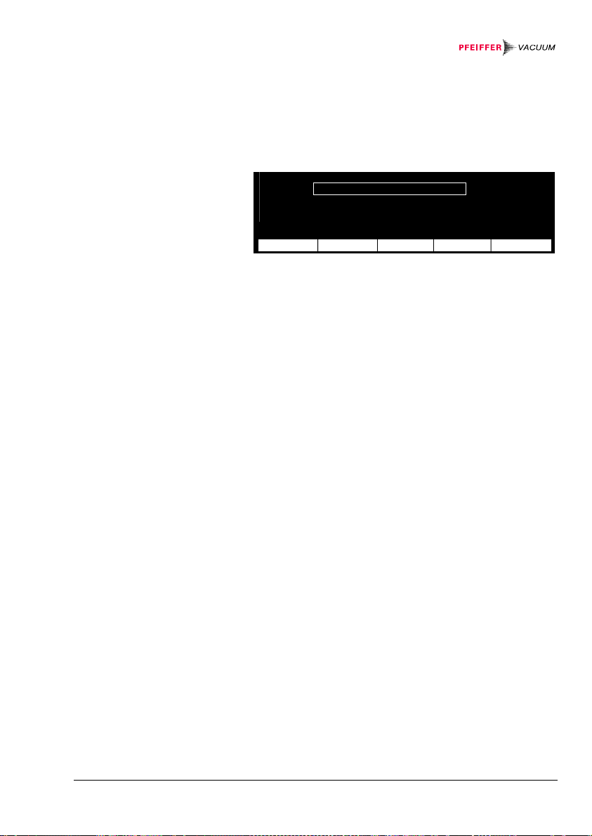
7.8.5 Setting the
S
«
Manual» Control
Figure 63:
Control Manual» display
«
You can turn on the controlled gauge with the [Sen-on]
softkey and turn it off with the [
Sen-off] softkey. If a
corresponding setpoint has been defined, the gauge can
also be turned off automatically in the event of a pressure rise.
Ò´Ô Control Manual
ñìí ON Key Sen-on
îïð OFF Selfcontrol
Ó½¾ OFF Threshold 1.00E-03 mbar
ensor next ®¯ ¬− Return
Setting the parameters:
• Select «
Control» «Manual» as controlling source
(→ 71)
• Press the [
next] softkey to select the «OFF» para-
meter
• Press the [
Key Sen-off» (unit is turned off with a softkey) or
«
Selfcontrol» (self-monitoring) parameter value
«
®¯] or [¬−] softkey to select the
Wen self-monitoring is selected, a fourth parameter line
«
OFF Threshold» is displayed. To define a setpoint,
proceed as follows:
• Press the [
OFF Threshold» parameter
«
• Press the [
next] softkey to select the
®¯] or [¬−] softkey to increase /decrease
the parameter value
• Press the [
Return] softkey to return to the
«Measurement» mode
BG 5186 BEN / C (2013-12) MaxiGauge.om Operation 73
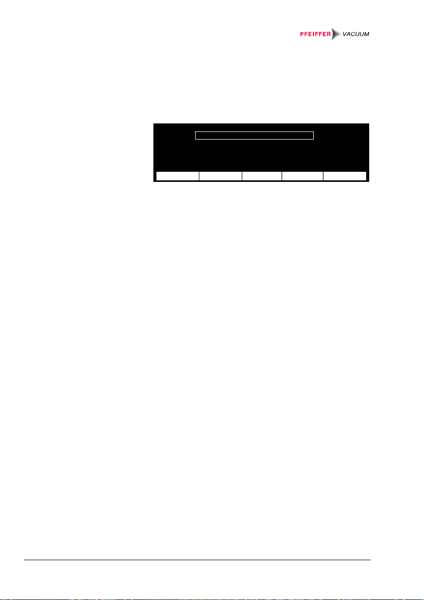
7.8.6 Setting the
S
«
Hotstart»
Control
Figure 64:
«
Hotstart» display
When the unit is switched on, the controlled gauge is
turned on automatically, and when the unit is switched
off, it is turned off, too. However, the controlled gauge
can also turn off itself in the event of a pressure rise
(Selfcontrol).
Ò´Ô Control Hotstart
ñìí ON Power on
îïð OFF Selfcontrol
Ó½¾ OFF Threshold 1.00E-03 mbar
ensor next ®¯ ¬− Return
Setting the parameters:
• Select «
Control» «Hotstart» as controlling
source (→ 71)
• Press the [
next] softkey to select the «OFF» para-
meter
• Press the[
Power off » (measurement point is turned off
«
when the unit is switched off) or «
®¯] or [¬−] softkey to select the
Selfcontrol»
(self-monitoring) parameter
when self-monitoring is selected, a fourth parameter line
OFF Threshold» is displayed. To define the setpoint,
«
proceed as follows:
• Press the [
OFF Threshold»
«
• Press the [
next] softkey to select the
®¯] or [¬−] softkey to increase / decrease
the parameter value
• Press the [
Return] softkey to return to the
«Measurement» mode
74 Operation
BG 5186 BEN / C (2013-12) MaxiGauge.om

7.9 Status Messages
S
5
Figure 65:
Status messages in
«Measurement» mode
Figure 66:
Status messages with different
gauges
Status messages are not to be confounded with error
messages. They only indicate the system status. If
status messages are displayed instead of measured
values, the received measurement signal is faulty.
1 CH 1 no Sensor A¡
2 CH 2 Sensor off B¢
3 CH 3 >1E-2 C£
4 CH 4 no ignition D¤
CH 5 Sensor error 1 E¥
6 CH 6 Sensor error 2 F¦
ensor Sen-off locked Single Mode
(Status message)
When status messages are displayed, proceed as follows:
• Find out why the received measurement signal is
faulty
After the problem is remedied, the measured value is
automatically displayed again.
locked *) Status message
TPR
IKR PKR APR
PCR
IMR PBR Meaning
CMR
ACR
*) In softkey display bar
Attempted entry with
activated input lock
no Sensor Status message
TPR
IKR PKR APR
PCR
IMR PBR Meaning
CMR
ACR
No gauge connected
Sensor off Status message
TPR
IKR PKR APR
PCR
IMR PBR Meaning
CMR
ACR
IKR, IMR, PKR, PBR
turned off
BG 5186 BEN / C (2013-12) MaxiGauge.om Operation 75
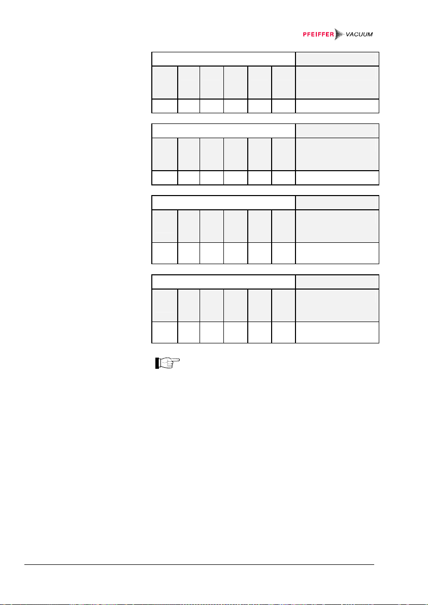
>"range" Status message
TPR
IKR PKR APR
PCR
IMR PBR Meaning
CMR
ACR
Overrange
<"range" Status message
TPR
IKR PKR APR
PCR
IMR PBR Meaning
CMR
ACR
Underrange
Sensor error 1 Status message
TPR
IKR PKR APR
PCR
IMR PBR Meaning
CMR
ACR
Measured value in
the lower error range
Sensor error 2 Status message
TPR
IKR PKR APR
PCR
IMR PBR Meaning
CMR
ACR
Measured value in
the upper error range
The «Sensor error 1 » and
«
Sensor error 2 » status messages do not
necessarily refer to the connected gauges 1
and 2 (see above for meaning of these status
messages).
76 Operation
BG 5186 BEN / C (2013-12) MaxiGauge.om
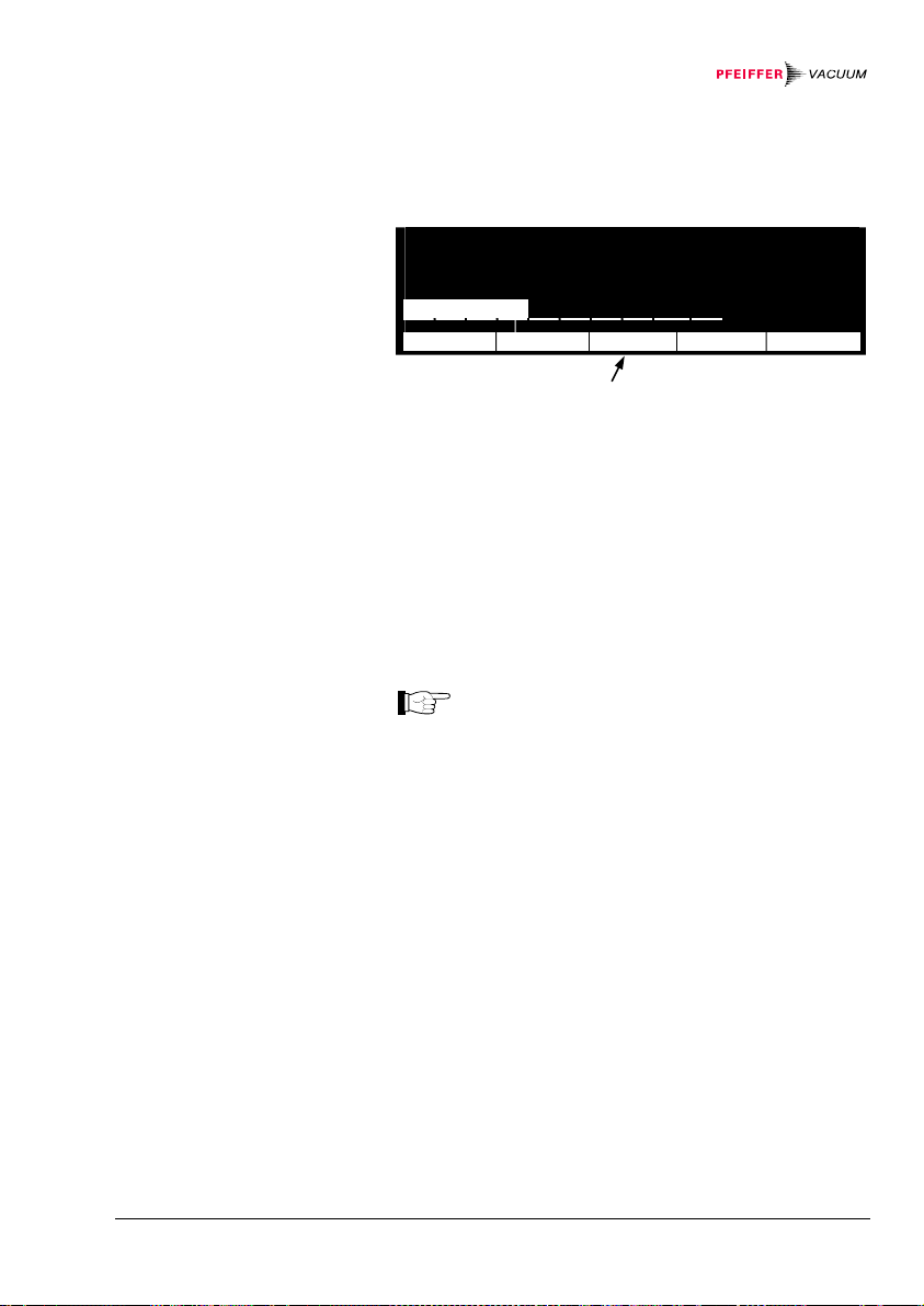
7.10 Error Messages
S
EEPROM
All
Figure 67:
EEPROM error in
«Measurement» mode
Acknowledging error
messages
Error messages are flashing in the display bar above the
middle softkey: Irregularities or disturbances have occurred. The error relay switches over (→ 22).
³´μ óÐ ¿À ³´μ Ò´Ô ³´μ ¿À A¡
óÅ ÆÑÁ ÃÁ Â Â Â Â ÃÁ cal B¢
ÆÇÈ ÉÊÎ Á ×ºÕ ÷º ÌÏ Â Â Á C£
ÉÊË CH 2 Áß ÍÎ ¼½¾ æ½Ë ¼½¾ ÍÎ mbar D¤
E¥
«1
ª0 F¦
ensor
Mode
(Error message is flashing)
When error messages are displayed, proceed as follows:
Acknowledging errors:
• Press the middle softkey. The error message is thus
erased and the next error message appears (if applicable)
After the error has been acknowledged, the error relay
switches back to its original position (→ 22).
• If the error message persists, switch the unit off and
on again
Wait at least 10 seconds before turning the unit
on again in order for it to correctly initialize
itself.
Depending on the setting of the system monitoring, certain error messages (e.g. watchdog errors) are automatically acknowledged after 2 seconds (→ 112) or they
have to be manually acknowledged.
The meanings of the error messages are listed in the
following table.
If the problem cannot be remedied, make a note of the
error message(s) and contact your nearest Pfeiffer
Vacuum Service Center.
BG 5186 BEN / C (2013-12) MaxiGauge.om Operation 77
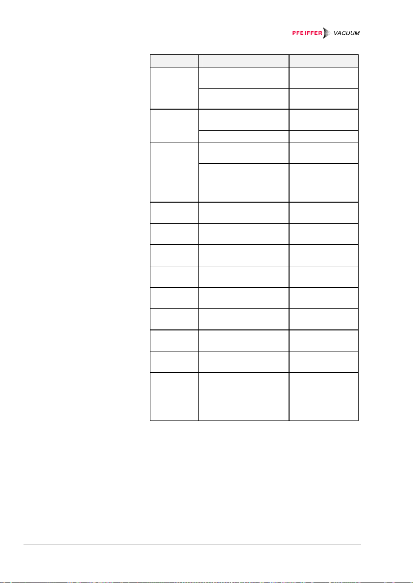
Figure 68:
Error message table
Display Possible cause Remedy
No display Power cable interrupted Check the power
cable
Mains voltage missing /
too high / too low
Display
dark
Screensave activated
(→ 56)
Check mains
voltage
Press a softkey
Lamp defective (life) Replace the lamp
WDT Operating system error
(watchdog error)
You have switched the
unit on to soon after
switching it off
Acknowledge
(→ 77)
Switch the unit
off, wait for 10
seconds and
switch it on again
TASK Operating system error
(task fail error)
IDLE Operating system error
(idle error)
STACK Operating system error
(stack overflow error)
RAM RAM error (data
memory)
EPROM EPROM error (program
memory)
EEPROM EEPROM error
(parameter memory)
Display Display-RAM error
(display memory)
KEY Softkey error Acknowledge
Acknowledge
(→ 77)
Acknowledge
(→ 77)
Acknowledge
(→ 77)
Acknowledge
(→ 77)
Acknowledge
(→ 77)
Acknowledge
(→ 77)
Acknowledge
(→ 77)
(→ 77)
ID1...ID6
Break in the line to the
corresponding gauge or
line has been disconnected during opera-
)
tion
*
Check the gauge
cable in question
Acknowledge
(→ 77)
*) If the cause has not been remedied, the «no Sensor» status
message is displayed.
78 Operation
BG 5186 BEN / C (2013-12) MaxiGauge.om

Display Possible cause Remedy
SE1...SE6 Sensor error *
)
Check according
to the following
examples
Acknowledging
error messages
(→ 77)
Pirani,
Pirani/Capacitance:
No supply
Measurement element faulty
Check supply and
cable
Maintain or exchange the
gauge
FullRange™ Gauge:
No supply
Pirani measurement
element faulty
Check supply and
cable
Maintain or exchange the
gauge
Cold cathode gauge:
No supply
Check supply and
cable
Linear gauge:
No supply
Check supply and
cable
Compact Process Ion
Gauge:
No Supply voltage
Check supply and
cable
)
*
At the same time, the status message «Sensor error 1»
(in the lower error range) or «Sensor error 2» (in the
upper error range) is displayed (→ 75).
BG 5186 BEN / C (2013-12) MaxiGauge.om Operation 79

8 Communication
8.1 Serial Interfaces
8.1.1 Connection
Diagrams
RS232C/422
Serial interface port
RS485/422 isol.
Serial interface port
Serial interfaces are used for communication between
the TPG 256 A and a computer (HOST). A terminal can
be connected for test purposes.
Pin assignment
1 Chassis
2 RXD (RS232C)
D-Sub, 9-pin, male
165
3 TXD (RS232C)
4 not connected
5 Signal ground
6 RX+ (RS422)
7 RX– (RS422)
8 TX+ (RS422)
9 TX– (RS422)
Pin assignment
9
Front view
RJ45, 8-pin
1 TX+
2 TX–
3 RX+
4 not connected
5 not connected
6 RX–
7 not connected
Front view
18
8 Isolation ground
80
Communication BG 5186 BEN / C (2013-12) MaxiGauge.om

8.1.2 Connection Cable
RS232C/422
Serial interface port
• Use shielded cable only
RS 432
PC MaxiGauge
RXD
TXD
RS485/422I isol.
Serial interface port
Caution
Only one of the two interfaces may be connected.
PC MaxiGauge
1Chassis
Chassis
RX+
RX–
RX+
6
RX–
7
TX+
8TX+
9TX– TX–
Chassis
1Chassis
2
RXD
TXD
3
5GND
Signal GND
RS 422 isol.
TM
• Use shielded RJ45 cable (STP)
• Wiring with cable pairs 1/2, 3/6, 4/5 and 7/8
Caution
The voltage difference between the Isol. GND and the
chassis may be max. 25 V for each MaxiGauge™.
RS 422 isol.
PC MaxiGauge
RX+
RX–
TX+
TX–
RS 485 isol.
PC MaxiGauge
RX+
RX–
TX+
TX–
TX+
11 11
22 22
TX–
RX+
33 33
66 66
RX–
44
55 55
77
8 Isol. GND 8GND 8 Isol. GND 8
TM
1
TX+
2
TX–
3
RX+
6
RX–
4
5
7
8 Isol. GND GND
TM
MaxiGauge
TM
TX+
TX–
RX+
RX–
44
77
TM
BG 5186 BEN / C (2013-12) MaxiGauge.om Communication 81

8.1.3 Data Transmission
Data format
Abbreviations and
symbols used
The data transmission is bi-directional (master-slave).
1 Start bit, 8 data bits, 1 stop bit, no parity bit,
no hardware handshake
Symbol Meaning
HOST Computer or terminal
[...] Optional elements
ASCII American Standard Code for Information
Interchange
Dec. Hex.
<ETX> END OF TEXT (CTRL C)
3 03
Reset the interface
<CR> CARRIAGE RETURN
13 0D
Go to beginning of line
<LF> LINE FEED
10 0A
Advance by one line
<ENQ> ENQUIRY
5 05
Request for data transmission
<ACK> ACKNOWLEDGE
6 06
Positive report signal
<NAK> NEGATIVE ACKNOWLEDGE
21 15
Negative report signal
<ESC> ESCAPE 27 1B
82
Communication BG 5186 BEN / C (2013-12) MaxiGauge.om

Flow control
Communication
protocol
Transmission
format
Transmission
protocol
Reception format
After each ASCII string the HOST must wait for a confirmation (<ACK> or <NAK>) <CR><LF> to ensure that
the input buffer of the TPG 256 A is empty.
The input buffer of the HOST must have a capacity of at
least 64 bytes.
Messages are transmitted to the TPG 256 A as ASCII
strings in the form of mnemonics and parameters. All
mnemonics comprise three ASCII characters.
Spaces are ignored. <ETX> clears the input buffer in the
TPG 256 A.
The input is terminated by <CR> or <LF> or <CR><LF>
("end of message"), and evaluation in the TPG 256 A is
subsequently started.
Do not transmit any LINE FEEDS (<LF>) via
the RS485 half duplex line for fear they could
cause data collisions on the bus.
The RS232C, RS422, RS422I and RS485
(fullduplex) interfaces permit transmitting LINE
FEEDS (<LF>). However, not transmitting them
makes data transmission faster.
The tables on 86 ff are applicable to the mnemonics and
parameters. The maximum number of digits, the data
formats and admissible value ranges are also specified
there.
HOST TPG 256 A Explanation
Mnemonics [and parameters]
<CR>[<LF>] ─────────────>
HOST transmits
message with "end
of message"
<───────── <ACK><CR><LF>
MaxiGauge™ transmits positive
acknowledgment of a
received message
The current parameters of the function can be inquired
by leaving out the [parameters].
When requested with a mnemonics, the TPG 256 A
transmits the measurement data or parameters as an
ASCII string to the HOST.
BG 5186 BEN / C (2013-12) MaxiGauge.om Communication 83

Reception protocol
<ENQ> must be transmitted to request the transmission
of an ASCII string. Additional strings, according to the
last selected mnemonic, are read out by repetitive transmission of <ENQ>.
If <ENQ> is received without a valid request, the error
status is transmitted.
HOST TPG 256 A Explanation
Mnemonics [and parameters]
<CR>[<LF>] ─────────────>
HOST transmits
message with "end
of message"
<───────── <ACK><CR><LF>
MaxiGauge™ transmits positive
acknowledgment of a
received message
<ENQ> ─────────────────>
The HOST invites
the MaxiGauge to
transmit data
Measurement values
or parameters
<────────────── <CR><LF>
MaxiGauge™ transmits data with "end
of message"
<ENQ> ──────────────────>
The HOST invites
the MaxiGauge to
transmit data
Measurement values
or parameters
<────────────── <CR><LF>
MaxiGauge™ transmits data with "end
of message"
84
Communication BG 5186 BEN / C (2013-12) MaxiGauge.om

Error processing
Error recognition
protocol
All messages received are verified in the TPG 256 A. If
an error is detected, a negative acknowledgment <NAK>
is output. The fault condition can subsequently be read
out (→ 98).
HOST TPG 256 A Explanation
Mnemonics [and parameters]
<CR>[<LF>] ─────────────>
HOST transmits
message with "end
of message"
***** Transmission or programming error *****
<───────── <NAK><CR><LF>
MaxiGauge™ transmits negative
acknowledgment of a
received message
Mnemonics [and parameters]
<CR>[<LF>] ─────────────>
HOST transmits
message with "end
of message"
<───────── <ACK><CR><LF>
MaxiGauge™ transmits positive
acknowledgment of a
received message
BG 5186 BEN / C (2013-12) MaxiGauge.om Communication 85

8.2 Mnemonics
Baud rate Baud rate 96
BAU
Calibration factor Sensor x Calibration factor sensor x (1 ... 6) 93
CAx
Measurement point names Measurement point names 89
CID
Display control Bargraph Bargraph 90
DCB
Display control Contrast Display control contrast 91
DCC
Display control Digits Display digits 89
DCD
Display control Screensave Display control screensave 91
DCS
Degas Degas 95
DGS
Error Status Error status 98
ERR
Filter time constant Filter time constant 93
FIL
Full scale range of linear sensors Full scale range of linear sensors 94
FSR
Parameter setup lock Parameter setup lock 93
LOC
Node (device) address for RS485 Node (device) address for RS485 96
NAD
Offset correction Offset correction 94
OFC
Program number Program number 99
PNR
Pirani range extension Pirani range extension 92
PRE
Status, Pressure sensor x (1 ... 6) Status, Pressure sensor x (1 ... 6) 89
PRx
Underrange Ctrl Underrange control 92
PUC
Interface Interface 95
RSX
Save default Save default 95
SAV
Sensor control Sensor control 88
SCx
Sensor on/off Sensor on/off 87
SEN
Set Point Control Source for Relay x Threshold value setting, Allocation 91
SPx
Set Point Status A,B,C,D,E,F Set point status 92
SPS
Test program A/D Identify Test A/D converter identification inputs 101
TAI
Test program A/D Sensor Test A/D converter measurement value
TAS
Display test Display test 99
TDI
EEPROM test EEPROM test 101
TEE
EPROM test EPROM test 100
TEP
Sensor identification Sensor identification 102
TID
Keyboard test Keyboard test 100
TKB
RAM test RAM test 100
TRA
Unit of measurement (Display) Unit of measurement (pressure) 90
UNI
Watchdog and System Error Control Watchdog and system error control 102
WDT
" Transmit "
" Receive "
inputs
"Transmit": Data transfer from HOST to TPG 256 A
"Receive": Data transfer from TPG 256 A to HOST
→
101
86
Communication BG 5186 BEN / C (2013-12) MaxiGauge.om

8.2.1 Measurement
Values
Sensor on / off
Transmit:
Receive:
Transmit:
Receive:
SEN [,x,x,x,x,x,x] <CR>[<LF>]
Sensors 1 ... 6
x = 0 ─> No change
1 ─> Off
2 ─> On
<ACK><CR><LF>
<ENQ>
x,x,x,x,x,x <CR><LF>
Status Sensors 1 ... 6
Not all sensor types can be switched on and
off.
BG 5186 BEN / C (2013-12) MaxiGauge.om Communication 87

Sensor control
Transmit:
Receive:
Transmit:
Receive:
SCx [,x,x,x.xE±yy,x.xE±yy] <CR> [<LF>]
Switching off value
Switching on value
Switch off the controlling source of the sensor
x = 0 ─> Sensor 1
1 ─> Sensor 2
2 ─> Sensor 3
3 ─> Sensor 4
4 ─> Sensor 5
5 ─> Sensor 6
6 ─> External control
7 ─> Manual (Default)
Switch on the controlling source of the sensor
x = 0 ─> Sensor 1
1 ─> Sensor 2
2 ─> Sensor 3
3 ─> Sensor 4
4 ─> Sensor 5
5 ─> Sensor 6
6 ─> External control
7 ─> Manual (Default)
8 ─> Hot start
Controlled sensor x = A ─> Sensor 1
B ─> Sensor 2
C ─> Sensor 3
D ─> Sensor 4
E ─> Sensor 5
F ─> Sensor 6
<ACK><CR><LF>
<ENQ>
x,x,x.xxE±y y,x.xxE±yy <CR><LF>
Switching off value
Switching on value
Switch off the controlling source of the gauge
Switch on the controlling source of the gauge
88
Communication BG 5186 BEN / C (2013-12) MaxiGauge.om

Status and pressure
Transmit:
Receive:
Transmit:
Receive:
Digits
Transmit:
Receive:
Transmit:
Receive:
Measurement point
names
Transmit:
PRx <CR>[<LF>]
Sensor x = 1 ... 6
<ACK><CR><LF>
<ENQ>
x,x.xxxEsx <CR><LF>
Measurement value (always exponential format)
Status
x = 0 ─> Measurement data okay
1 ─> Underrange
2 ─> Overrange
3 ─> Sensor error
4 ─> Sensor off
5 ─> No sensor
6 ─> Identification error
DCD [,x] <CR>[<LF>]
Digits x = 2 ─> Display x.x (2 digits) (default)
3 ─> Display x.xx (3 digits)
<ACK><CR><LF>
<ENQ>
x <CR><LF>
Digits
When Range-Ext is on, the display resolution of the PCR
and TPR gauges in the pressure range p<1.0E-4 mbar is
reduced by one decimal digit.
CID [,xxxx,xxxx,xxxx,xxxx,xxxx,xxxx] <CR>[<LF>]
Measurement point
name 6
Measurement point
name 5
Measurement point name 4
Measurement point name 3
Measurement point name 2
Measurement point name 1
BG 5186 BEN / C (2013-12) MaxiGauge.om Communication 89

Receive:
Transmit:
Receive:
8.2.2 Display
Unit of
measurement
Transmit:
Receive:
Transmit:
Receive:
Bargraph
Transmit:
Receive:
Transmit:
Receive:
All channel names are ASCII strings (A ... Z;
0 ... 9). Blanks (spaces) are ignored.
<ACK><CR><LF>
<ENQ>
xxxx,xxxx,xxxx,xxxx,xxxx,xxxx <CR><LF>
Measurement point names
The selected measurement unit has only an
effect on the display, i.e. it does not affect the
accuracy of the measurement.
UNI [,x] <CR>[<LF>]
Measurement unit x = 0 ─> mbar (Default)
1 ─> Torr
2 ─> Pascal
<ACK><CR><LF>
<ENQ>
x <CR><LF>
Measurement unit
DCB [,x] <CR>[<LF>]
Bargraph x = 0 ─> Off (default)
1 ─> Bargraph = Measurement
range
2 ─> Bargraph = 1 decade
<ACK><CR><LF>
<ENQ>
x <CR><LF>
Bargraph
90
Communication BG 5186 BEN / C (2013-12) MaxiGauge.om

Contrast
Transmit:
Receive:
Transmit:
Receive:
Screensave
Transmit:
Receive:
Transmit:
Receive:
8.2.3 Switching
Functions
Threshold value
setting, Allocation
Transmit:
DCC [,xx] <CR>[<LF>]
Contrast x = 0 ... 20 ─> Contrast dark ... light
(Default = 10 (med.))
<ACK><CR><LF>
<ENQ>
xx <CR><LF>
Contrast
DCS [,xx] <CR>[<LF>]
Screensave
x = 0 ─> Screensave off (default)
1 ... 99 ─> Screensave after 1 ... 99 h
<ACK><CR><LF>
<ENQ>
xx <CR><LF>
Screensave
SPx [,x,x.xxEsx,x.xxEsx] <CR>[<LF>]
Upper threshold [mbar]
(default = 9.00E-11)
Lower threshold [mbar]
(always exponential format)
(default = 1.00E-11)
Source x = 0 ... 5 ─> sensors 1 ... 6
Switching function (Relay) x = 1 ... 6 ─> A ... F
BG 5186 BEN / C (2013-12) MaxiGauge.om Communication 91

Receive:
Transmit:
Receive:
Set point status
Transmit:
Receive:
Transmit:
Receive:
Underrange control
Transmit:
Receive:
Transmit:
Receive:
8.2.4 Parameters
Pirani range
extension
Transmit:
<ACK><CR><LF>
<ENQ>
x,x.xxEsx,x.xxEsx <CR><LF>
Upper threshold
Lower threshold
Sensor (source)
SPS <CR>[<LF>]
<ACK><CR><LF>
<ENQ>
x,x,x,x,x,x <CR><LF>
Set point A ... F x = 0 ─> off
1 ─> on
PUC [,x,x,x,x,x,x] <CR>[<LF>]
Underrange control A ... F
x = 0 ─> UR control deactivated (default)
1 ─> UR control activated
<ACK><CR><LF>
<ENQ>
x,x,x,x,x,x <CR><LF>
Underrange control
PCR and TPR gauges only, measurement range up to
-5
5×10
mbar.
PRE [,x,x,x,x, x,x] <CR>[<LF>]
Pirani range extension sensors 1 ... 6
x = 0 ─> deactivated (default)
1 ─> activated
92
Communication BG 5186 BEN / C (2013-12) MaxiGauge.om

Receive:
Transmit:
Receive:
Entry lock function
Transmit:
Receive:
Transmit:
Receive:
Filter time constants
Transmit:
Receive:
Transmit:
Receive:
Calibration factor
Transmit:
<ACK><CR><LF>
<ENQ>
x,x,x,x,x,x <CR><LF>
Range extension
LOC [,x] <CR>[<LF>]
Entry lock function x = 0 ─> off (default)
<ACK><CR><LF>
<ENQ>
x <CR><LF>
Entry lock function
FIL [,x,x,x,x,x,x] <CR>[<LF>]
Filter time constant sensors 1 ... 6
x = 0 ─> fast
1 ─> standard (default)
2 ─> slow
<ACK><CR><LF>
<ENQ>
x,x,x,x,x,x <CR><LF>
Filter time constant
CAx [,x.xxx] <CR>[<LF>]
Calibration factor
for logarithmic sensors (default = 1.000)
Calibration factor 0.500 ... 2.000
for linear sensors (default = 1.000)
Sensor x = 1 ... 6
1 ─> on
0.100 ... 9.999
BG 5186 BEN / C (2013-12) MaxiGauge.om Communication 93

Receive:
Transmit:
Receive:
Offset correction
Transmit:
Receive:
Transmit:
Receive:
Measurement range
Transmit:
Receive:
Transmit:
Receive:
<ACK><CR><LF>
<ENQ>
x.xxx <CR><LF>
Calibration factor
OFC [,x,x,x,x,x,x] <CR>[<LF>]
Offset correction sensors 1 ... 6
x = 0 ─> off (default)
1 ─> activated
2 ─> actual measurement value =
offset value
<ACK><CR><LF>
<ENQ>
x,x,x,x,x,x <CR><LF>
Offset correction
For linear gauges, the maximum pressure
should be defined (full scale value). For
logarithmic gauges the measurement range is
detected automatically.
FSR [,x,x,x,x,x,x] <CR>[<LF>]
full scale
range sensors 1 ... 6
x = 0 ─> 1 mbar
1 ─> 10 mbar
2 ─> 100 mbar
3 ─> 1000 mbar (default)
4 ─> 2 bar
5 ─> 5 bar
6 ─> 10 bar
7 ─> 50 bar
8 ─> 0.1 mbar
<ACK><CR><LF>
<ENQ>
x,x,x,x,x,x <CR><LF>
Measurement ranges
94
Communication BG 5186 BEN / C (2013-12) MaxiGauge.om
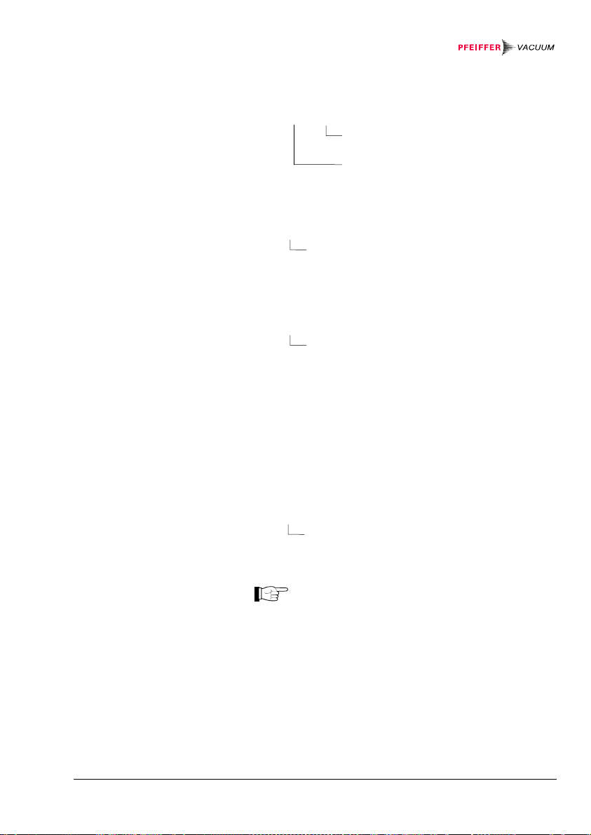
Degas
Transmit:
Receive:
Transmit:
Receive:
Default
Transmit:
Receive:
8.2.5 Interfaces
Interface
Transmit:
Receive:
Transmit:
DGS [,0,0,0,x,x,x] <CR>[<LF>]
x = 0 ─> Degas off
1 ─> Degas on
Sensors 1 … 3: no degas
<ACK><CR><LF>
<ENQ>
0,0,0,x,x,x <CR><LF>
Degas status
SAV [,1] <CR>[<LF>]
Activate the factory setting
<ACK><CR><LF>
This functions is only useful if several interfaces are
connected to the unit.
RSX [,x] <CR>[<LF>]
Interface x = 0 ─> RS232C (default)
1 ─> RS422
2 ─> RS422I isolated
3 ─> RS485 isolated
The RS485 interface allows to assign
addresses to the connected units. The node (or
device) address of each unit can be defined
(→ 55). When replacing a unit, don't forget to
enter the corresponding address number
(→ 96).
<ACK><CR><LF>
<ENQ>
BG 5186 BEN / C (2013-12) MaxiGauge.om Communication 95

Receive:
Baud rate
Transmit:
Receive:
Transmit:
Receive:
RS485 node address
Transmit:
Receive:
Transmit:
Receive:
In order not to interrupt the communication, set
the HOST to the same interface as the
TPG 256 A.
x <CR><LF>
Interface
BAU [,x] <CR>[<LF>]
Baud rate x = 0 ─> 300 baud
1 ─> 1200 baud
2 ─> 2400 baud
3 ─> 4800 baud
4 ─> 9600 baud (default)
5 ─> 19200 baud
As soon as the new baud rate has been
entered, the report signal is transmitted at the
new baud rate.
<ACK><CR><LF>
<ENQ>
x <CR><LF>
Baud rate
NAD xx <CR>[<LF>]
Node address of the unit
x = 00 ... 31 ─> Node address 00 ... 31
<ACK><CR><LF>
<ENQ>
xx <CR><LF>
Node address of the unit
96
Communication BG 5186 BEN / C (2013-12) MaxiGauge.om

Addressing the unit
Transmit:
Do not transmit any LINE FEEDS (<LF>) via the
RS485 half duplex line for fear they could
cause data collisions on the bus.
The RS232C, RS422, RS422I and RS485
(fullduplex) interfaces permit transmitting LINE
FEEDS (<LF>). However, not transmitting them
makes data transmission faster.
Entering the corresponding node address connects the
unit connects to the HOST. The other units release the
bus.
<ESC>xx
Node address of the unit
xx = 00 ... 31
All node addresses have two digits (00 ... 31).
The address must always be transmitted when
a different unit is to be accessed.
BG 5186 BEN / C (2013-12) MaxiGauge.om Communication 97

8.2.6 Error Messages
Error status
Transmit:
Receive:
Transmit:
Receive:
ERR <CR>[<LF>]
<ACK><CR><LF>
<ENQ>
xxxxx,xxxxx <CR><LF>
Error status
xxxxx = 0 ─> No error
1 ─> Sensor 1: Measurement error
2 ─> Sensor 2: Measurement error
4 ─> Sensor 3: Measurement error
8 ─> Sensor 4: Measurement error
16 ─> Sensor 5: Measurement error
32 ─> Sensor 6: Measurement error
512 ─> Sensor 1: Identification error
1024 ─> Sensor 2: Identification error
2048 ─> Sensor 3: Identification error
4096 ─> Sensor 4: Identification error
8192 ─> Sensor 5: Identification error
16384 ─> Sensor 6: Identification error
Error status
xxxxx = 0 ─> No error
1 ─> Watchdog has responded
2 ─> Task fail error
4 ─> IDCX idle error
8 ─> Stack overflow error
16 ─> EPROM error
32 ─> RAM error
64 ─> EEPROM error
128 ─> Key error
4096 ─> Syntax error
8192 ─> Inadmissible parameter
16384 ─>
No hardware
32768 ─> Fatal error
98
Communication BG 5186 BEN / C (2013-12) MaxiGauge.om

8.2.7 Test Programs for
Pfeiffer Vacuum
Service Specialists
Program version
Transmit:
Receive:
Transmit:
Receive:
Display test
Transmit:
Receive:
Transmit:
Receive:
Some test programs take several seconds to
transmit a report signal.
Once a test program is started, the «Test»
mode remains active until the unit is switched
PNR <CR>[<LF>]
off.
<ACK><CR><LF>
<ENQ>
BGxxxxxx-x
Index (-, A, B ... Z)
Program version
TDI <CR>[<LF>]
<ACK><CR><LF>
<ENQ>
xxxxx,xxxxx <CR><LF>
Error status → 98
BG 5186 BEN / C (2013-12) MaxiGauge.om Communication 99

Keyboard test
Transmit:
Receive:
Transmit:
Receive:
RAM test
Transmit:
Receive:
Transmit:
Receive:
EPROM test
Transmit:
Receive:
Transmit:
Receive:
TKB <CR>[<LF>]
<ACK><CR><LF>
<ENQ>
xx <CR><LF>
xx = 1 ─> Bit 0 = 1 Key 1 pressed
2 ─> Bit 1 = 1 Key 2 pressed
4 ─> Bit 2 = 1 Key 3 pressed
8 ─> Bit 3 = 1 Key 4 pressed
16 ─> Bit 4 = 1 Key 5 pressed
nn ─> nn = Sum of the values of the pressed
keys
TRA <CR>[<LF>]
<ACK><CR><LF>
<ENQ>
xxxxx,xxxxx <CR><LF>
Error status → 98
TEP <CR>[<LF>]
<ACK><CR><LF>
<ENQ>
xxxxx,xxxxx <CR><LF>
Error status → 98
100
Communication BG 5186 BEN / C (2013-12) MaxiGauge.om
 Loading...