


(
)
OPERATING INSTRUCTIONS
Translation of the original instructions
PBR 260
Compact FullRange® BA Gauge
2017-02
BG 5171 BEN / B

Product Identification
In all communications with Pfeiffer Vacuum, please specify the information given
on the product nameplate. For convenient reference copy that information into the
space provided below.
Pfeiffer Vacuum, D-35614 Asslar
Typ:
No:
F-No:
V W
Validity
This document applies to products with part number
PT R27 000
(Flange DN 25 ISO-KF)
PT R27 001 (Flange DN 40 ISO-KF)
PT R27 002 (Flange DN 40 CF-R)
The part number (No) can be taken from the product nameplate.
If not indicated otherwise in the legends, the illustrations in this document correspond to the gauge with the vacuum connection DN 25 ISO-KF. They apply to
gauges with other vacuum connections by analogy.
We reserve the right to make technical changes without prior notice.
Intended Use
The PBR 260 Compact FullRange® BA Gauge has been designed for vacuum
measurement of non-flammable gases and gas mixtures in the pressure range of
-10
... 1000 hPa.
5×10
It must not be used for measuring flammable or combustible gases in mixtures
containing oxidants (e.g. atmospheric oxygen) within the explosion range.
The PBR 260 is part of the Pfeiffer Vacuum Compact Gauges family and can be
operated in connection with the MaxiGauge™ measurement and control unit
TPG 256 A or with another evaluation unit.
Functional Principle
Over the whole measurement range, the Compact FullRange® BA Gauge has a
continuous characteristic curve and its measuring signal is output as a logarithm of
the pressure.
The gauge functions with a Bayard Alpert hot cathode ionization and a Pirani
measurement system. In a defined overlapping pressure range, a mixed signal of
the two measurement systems is output. Above that range, a Pirani signal, below
that range, a hot cathode signal is output. The Pirani signal switches the hot
cathode measurement system on and off to prevent filament burn-out and
excessive contamination. The user can select among two switching on/off
thresholds.
Trademarks
MaxiGauge™ INFICON GmbH
FullRange
®
Pfeiffer Vacuum GmbH
2
BG 5171 BEN / B (2017-02) PBR 260

Contents
Product Identification 2
Validity 2
Intended Use 2
Functional Principle 2
Trademarks 2
1
Safety 4
1.1 Symbols Used 4
1.2 Personnel Qualifications 4
1.3 General Safety Instructions 4
1.4 Liability and Warranty 4
2 Technical Data 5
3 Installation 9
3.1 Vacuum Connection 9
3.1.1 Removing and Installing the Electronics Unit 10
3.1.2 Mounting the Extension 12
3.2 Power Connection 13
3.2.1 Use With MaxiGauge™ 13
3.2.2 Use With Other Evaluation Units 13
4 Operation 15
4.1 Measuring Principle, Measuring Behavior 15
4.2 Operational Principle of the Gauge 18
4.3 Degas 18
5 Maintenance 19
5.1 Maintenance 19
5.2 Adjusting the Gauge 19
5.3 Cleaning the Gauge 20
5.4 Installing the Baffle 20
5.5 Replacing the Baffle 22
5.6 Replacing the Sensor 23
5.7 What to Do in Case of Problems 23
6 Deinstallation 24
7 Returning the Product 26
8 Options 26
9 Spare Parts 26
10 Disposal 27
Appendix 28
A: Conversion Table for Pressure Units 28
B: Relationship Measuring Signal – Pessure 28
C: Gas Type Dependence 29
For cross-references within this document, the symbol (→ XY) is used, for cross-
references to other documents, the symbol (→ [Z]).
BG 5171 BEN / B (2017-02) PBR 260.oi 3

1 Safety
1.1 Symbols Used
1.2 Personnel Qualifications
1.3 General Safety
Instructions
1.4 Liability and Warranty
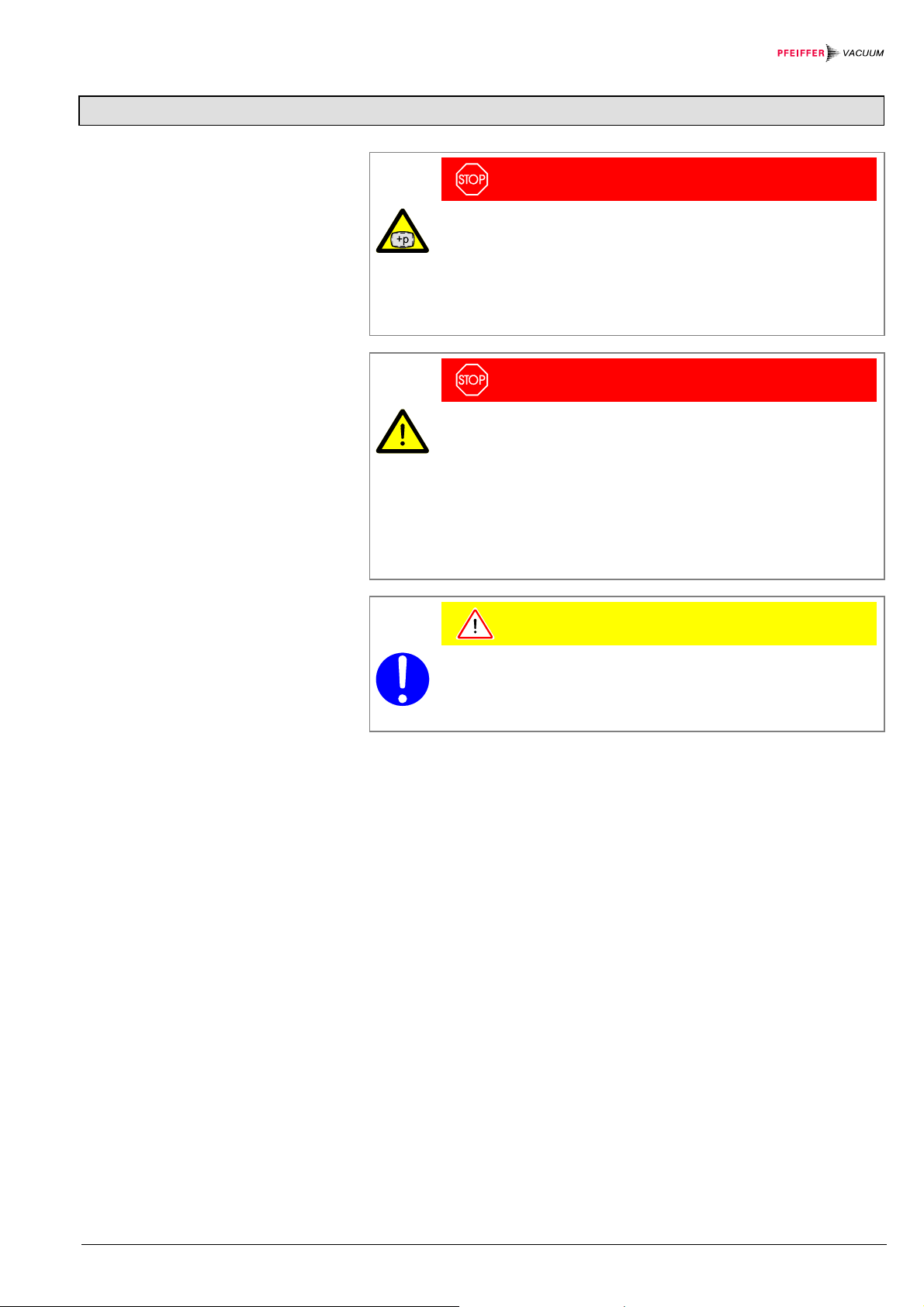
DANGER
Information on preventing any kind of physical injury.
WARNING
Information on preventing extensive equipment and environmental damage.
Caution
Information on correct handling or use. Disregard can lead to malfunctions or
minor equipment damage.
Skilled personnel
All work described in this document may only be carried out by persons who
have suitable technical training and the necessary experience or who have been
instructed by the end-user of the product.
• Adhere to the applicable regulations and take the necessary precautions for the
process media used.
Consider possible reactions between the materials (→ 6) and the process
media.
Consider possible reactions (e.g. explosion) of the process media due to heat
generated by the product.
• Adhere to the applicable regulations and take the necessary precautions for all
work you are going to do and consider the safety instructions in this document.
• Before beginning to work, find out whether any vacuum components are contaminated. Adhere to the relevant regulations and take the necessary precautions when handling contaminated parts.
Communicate the safety instructions to other users.
Pfeiffer Vacuum assumes no liability and the warranty becomes null and void if the
end-user or third parties
• disregard the information in this document
• use the product in a non-conforming manner
• make any kind of changes (modifications, alterations etc.) to the product
• use the product with accessories not listed in the corresponding product
documentation.
The end-user assumes the responsibility in conjunction with the process media
used.
Gauge failures due to contamination or wear and tear, as well as expendable parts
(e.g. filament), are not covered by the warranty.
4
BG 5171 BEN / B (2017-02) PBR 260

2 Technical Data
Measurement
Emission
Degas
(only if p < 7.2×10
Output signal
Gauge identification
-6
hPa)
.
Measurement range (air, N2) 5×10
Overlapping range hot cathode – Pirani
high (default)
low
Accuracy
-8
... 10-2 hPa)
(10
Repeatability
-8
... 10-2 hPa)
(10
-10
… 1000 hPa
–3
5.5×10
2.0×10
… 2.0×10⁻² hPa
–3
… 8.0×10⁻³ hPa
≈15 % reading
(after 5 min. stabilization)
≈5 % reading
(after 5 min. stabilization)
Gas type dependence → Appendix C
Switching on threshold (high) (default)
Switching off threshold (high) (default)
Switching on threshold (low)
Switching off threshold (low)
Emission current
(with decreasing pressure)
-6
7.2×10
hPa < p < 2.4×10⁻² hPa
p ≤ 7.2×10
-6
hPa
Emission current switching
25 µA 5 mA
(with decreasing pressure)
5 mA 25 µA
2.4×10⁻² hPa
-2
3.2×10
9.9×10
1.3×10
hPa
-3
hPa
-2
hPa
25 µA
5 mA
-6
7.2×10
hPa
3.2×10⁻⁵ hPa
(with increasing pressure)
Current ca. 16 mA / ca. 4.0 W
Control input signal 0 V / 24 V, PLC level, high active
Duration max. 3 min., followed by automatic stop
In degas mode, the PBR 260 keeps supplying measurement values the tolerances
of which can be higher than during normal operation.
Output signal 0 … 10.2 V
Measurement range 0.774 V … 10 V
(5×10
-10
hPa … 1000 hPa)
Relationship voltage-pressure logarithmic, 0.75 V / decade
Error signals
0.3 V
0.5 V
→ 23
• hot cathode error
• Pirani error
• electronics unit not correctly
mounted on sensor
Underrange
Overrange
0.5 V < U < 0.774 V
10 V < U ≤ 10.2 V
(measuring signal limited to 10.2 V by
software)
Minimum load
10 kΩ
Resistor (pin 1, U
= 4.25 V)
max
17.2 kΩ referenced to supply common
BG 5171 BEN / B (2017-02) PBR 260.oi 5

pp
pp
Adjustment
Supply
Sensor cable
Grounding concept
Vacuum
Pirani
HV
ATM (<ATM> button)
Zero point adjustment (<ATM>
button)
automatic adjustment by hot cathode
system at p = 1 … 3×10⁻³ hPa
adjustment via <ATM> button (keep
button depressed for at least 5 seconds)
at atmospheric pressure
adjustment via <ATM> button (keep
button depressed for at least 2 seconds)
at ≤1×10
-4
hPa
Hot cathode factory calibrated, readjustment not
required
DANGER
The gauge may only be connected to supply and evaluation units
which conform to the requirements of a grounded protective extra-low
Voltage at gauge 20 … 30 V=
Power consumption
standard
degas
emission start (< 200 ms)
Power consumption ≤ 16 W
Fuse necessary 1) ≤ 1.25 AT
Voltage at the supply unit with
maximum cable length
Electrical connection Hirschmann compact connector
Tightening torque ≤ 0.2 Nm
Cable 5 poles plus shielding
Cable length max. 35 m (0.25 mm² conductor)
Vacuum flange-supply common conductively connected
Signal common-supply common conducted separately; only differential
Materials on the vacuum side
housing, supports, screens
feedthrough
isolator
cathode
cathode holder
Pirani element
Internal volume
DN 25 ISO-KF
DN 40 ISO-KF
DN 40 CF-R
Pressure max. 200 kPa (absolute)
voltage (PELV). The connection to the gauge has to be fused. 1)
2)
max. ripple 2 V
≤ 0.5 A
≤ 0.8 A
≤ 1.4 A
21 … 30 V
max. ripple 2 V
type GO 6, 6 poles, male
50 m (0.34 mm² conductor)
100 m (1.0 mm² conductor)
measurement admissible due to high
current consumption
stainless steel
NiFe nickel plated
glass
iridium, yttrium oxide
molybdenum
tungsten, copper
≤ 24 cm
≤ 24 cm
3
3
≤ 34 cm3
1)
The MaxiGauge™ fulfills these requirements.
2)
The minimum voltage of the power supply must be increased proportionally to the length of the sensor
cable.
6
BG 5171 BEN / B (2017-02) PBR 260

Ambiance
Dimensions
Admissible temperatures
storage
operation
bakeout
-20 °C … 70 °C
0 °C … 50 °C
+150 °C (without electronics unit or with
extension → 26)
Relative humidity
year's mean
during 60 days
≤ 65 % (no condensation)
≤ 85 % (no condensation)
Use indoors only
altitude up to 2000 m NN
Degree of protection IP 30
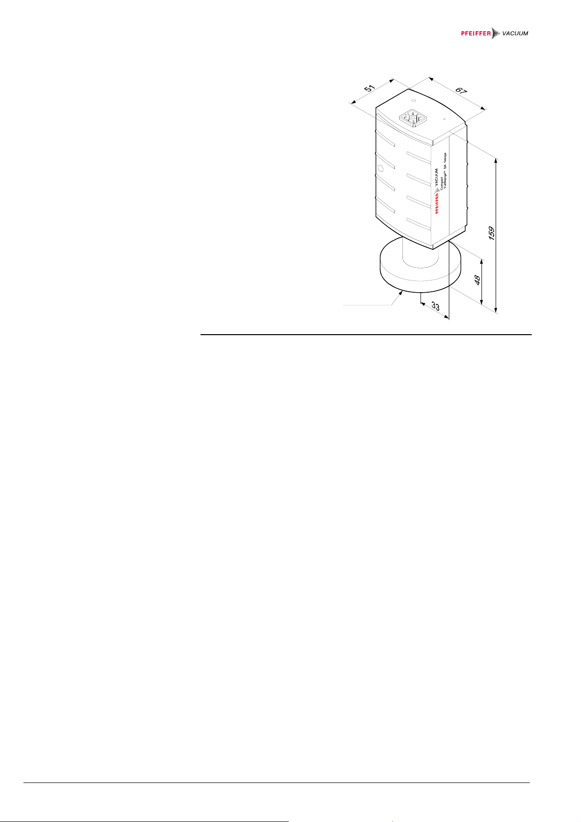
Flange DN 25 ISO-KF
Dimensions [mm]
DN 25 KF
Weight 285 g
Flange DN 40 ISO-KF
Dimensions [mm]
DN 40 KF
Weight 315 g
BG 5171 BEN / B (2017-02) PBR 260.oi 7
Flange DN 40 CF-R
Dimensions [mm]
DN 63 CF-R
Weight 550 g
8
BG 5171 BEN / B (2017-02) PBR 260
3 Installation
3.1 Vacuum Connection
DANGER: overpressure in the vacuum system > 100 kPa
If clamps are opened incorrectly or inadvertently, injury can be caused
by catapulted parts and your health can get damaged by leaking process media.
Do not open any clamps while the vacuum system is pressurized. Use
the type of clamps which cannot be opened inadvertently (e.g. hose
clip clamping rings).
DANGER: hazardous voltages
Incorrectly grounded products can be extremely hazardous in the
event of a fault.
The gauge must be electrically connected to the grounded vacuum
chamber. This connection must conform to the requirements of a
protective connection according to EN 61010:
• CF flanges fulfill this requirement.
• For gauges with a KF flange, use a conductive metallic clamping
ring.
DANGER
DANGER
Caution
Caution: vacuum component
Dirt and damages impair the function of the vacuum component.
When handling vacuum components, take appropriate measures to
• The gauge should be mounted so that no vibrations occur.
• The gauge may be mounted in any direction. However, no particles and con-
densates should penetrate into the measuring chamber.
• Take appropriate measures to prevent overheating (
admissible operating temperature).
• The sensor can be baked out at up to 150 °C. For temperatures above 50 °C
the electronics unit must be removed (→ 10) or an extension (Option → 26)
must be mounted (→ 12).
• See dimensional drawings ( 7) for space requirements.
• If the flange connection can only be made without the electronics unit, remove
the electronics unit (→ 10).
• We recommend using a metal sealing (ultra sealing ring → 26) as vacuum
flange sealing because elastomer seals (Vitilan, FPM) can impair the measurement accuracy already in the 10
• The gauge is supplied with a built in grid. For potentially severely contaminating
applications and to protect the electrodes against light and fast particles
installation of the optional baffle (→ 26) is recommended (→ 22).
ensure cleanliness and prevent damages.
-6
hPa range through gas desorption.
→ Technical data for
BG 5171 BEN / B (2017-02) PBR 260.oi 9

Procedure
Remove the protective cap.
The protective cap
will be needed for
maintenance.
Make the flange connection.
3.1.1 Removing and Installing
the Electronics Unit
Tools / material required
Removal
Install the gauge in such a way that it need not be removed for adjustment
(→ 17, 19).
• Allen wrench 2.5 mm
10
BG 5171 BEN / B (2017-02) PBR 260

a) Unscrew the hexagon socket screw (1) on the side of the electronics unit (2).
Be careful not to lose the hexagon socket screw.
1
2
b) Remove the electronics unit without twisting it.
Mounting
a) Place the electronics unit on the sensor (3) (be careful to correctly position the
pins and the guide notch (4)).
4
3
b) Slide the electronics unit up to the mechanical stop and lock it with the hexagon
socket screw (1).
BG 5171 BEN / B (2017-02) PBR 260.oi 11

3.1.2 Mounting the Extension
Bakeout area
With the optional extension (→ 26) the sensor can also be baked during opera-
tion at temperatures up to 150 °C (only at p<10
furnishes inexact readings at higher temperatures).
-2
hPa, since the Pirani sensor
Caution
Caution: rising heat
If your gauge is installed vertically, heat can rise even through the
extension and possibly damage the electronics unit.
Mount the gauge horizontally.
123
Compact
FullRange
VACUUM
TM
BA Gauge
Procedure
Bakeout area
a) Remove the electronics unit (2) (→ 10).
b) Slide the sensor (3) into the extension (6) to the mechanical stop (be careful to
correctly position the pins and the guide notch (4)).
c) Secure the sensor with the hexagon socket screws (7).
4a
4
2
3
1
6
7
d) Slide the electronics unit (2) onto the extension until the mechanical stop is
reached (be careful to correctly position the pins and the guide notch (4a)).
e) Secure the electronics unit (2) with the hexagon socket screw (1).
12
BG 5171 BEN / B (2017-02) PBR 260

3.2 Power Connection
3.2.1 Use With MaxiGauge™
3.2.2 Use With Other
Evaluation Units
Procedure
If the gauge is used with a
MaxiGauge™ measurement and
control unit, a corresponding
sensor cable is required
(→ 26).
• Plug the connector into the
gauge and secure it with the
screw (tightening torque
≤ 0.2 Nm).
• Connect the other end of the
cable to the MaxiGauge™
and secure it.
The gauge can also be used with other evaluation units. In such a case, an individual sensor cable can be made (preconfigured cables → 26).
Due to the high current consumption, only differential measurement between the
signal output (pin 2) and signal common (pin 3) is admissible.
Prepare the connector
(ordering number
→ 26).
Prepare the cable.
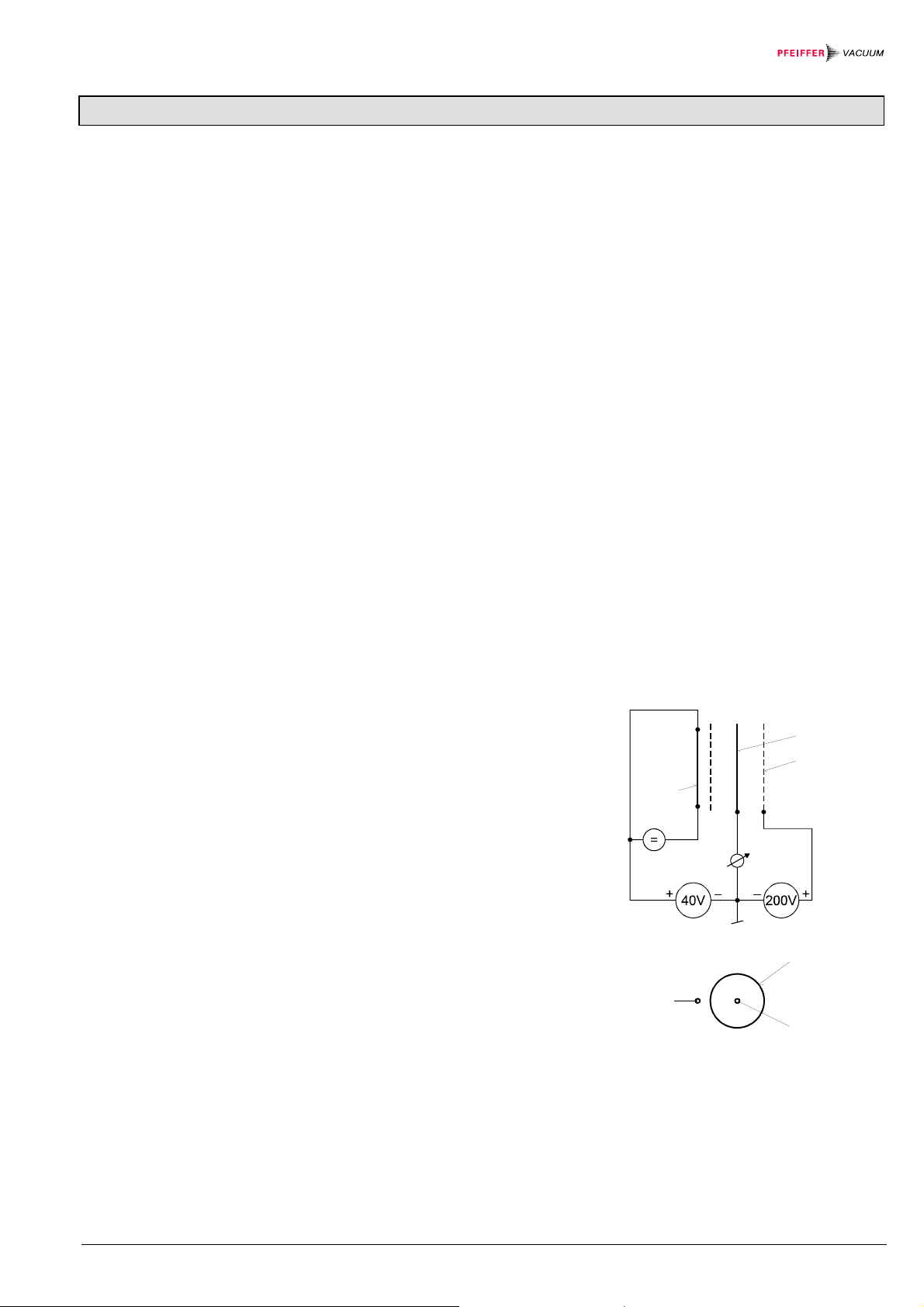
Solder the sensor cable according to the diagram.
Degas
17.2 k
Figure 1: Electrical connection
Pin 1 a) degas
b) identification
(U ≤ 4.25 V)
Pin 2 signal output
(measuring signal)
Pin 3 signal common GND
Pin 4 supply
Pin 5 supply common GND
Pin 6 shielding
2
3
1
4
5
6
Degas
3
4
+
–
+
–
2
1
6
5
Connector, soldering side
BG 5171 BEN / B (2017-02) PBR 260.oi 13

WARNING
The supply common (pin 5) and the shield (pin 6) must be
connected at the supply unit with protective ground.
Incorrect connection, incorrect polarity or inadmissible supply
Reassemble the connector.
At the other end of the cable, mount a connector which is compatible with
your evaluation unit.
Plug in the connector.
Secure the connector on the gauge with
the screw (tightening torque ≤ 0.2 Nm).
voltages can damage the gauge.
Connect the other end of the cable to your evaluation unit.
14
BG 5171 BEN / B (2017-02) PBR 260
4 Operation
4.1 Measuring Principle,
Measuring Behavior
Bayard Alpert
When the voltage is supplied, the measuring signal is available between pins 2 and
3. Over the whole measurement range, the measuring signal is output as a
logarithm of the pressure (relationship between measuring signal and pressure
→ Appendix B).
Allow for a stabilizing time of approx. 10 min. Once the gauge has been switched
on, permanently leave it on irrespective of the pressure.
The PBR 260 consists of two separate measuring systems (hot cathode Bayard
Alpert (BA) and Pirani).
The BA measuring system uses an electrode system according to Bayard Alpert
which is designed for a low x-ray limit.
The measuring principle of this system is based on gas ionization. Electrons
emitted by the hot cathode (F) ionize a number of molecules proportional to the
pressure in the measuring chamber. The ion collector (IC) collects the thus
generated ion current I
ment instrument. The ion current is dependent upon the emission current I
and feeds it to the electrometer amplifier of the measure-
+
, the
e
gas type, and the gas pressure p according to the following relationship:
= Ie × p × C
I
+
Factor C represents the sensitivity of the gauge. It is generally specified for N
The lower measurement limit is 5×10
For the whole range of 5x10
-10
-10
hPa (metal sealed).
hPa ... 10-2 hPa to be sensibly covered, a low
.
2
emission current is used in the high pressure range (fine vacuum) and a high
emission current is used in the low pressure range (high vacuum). The switching of
the emission current takes place at decreasing pressure at approx. 7.2×10
at increasing pressure at approx. 3.2×10
PBR 260 can temporarily (< 2 s) deviate from the specified accuracy.
-5
hPa. At the switching threshold the
-6
hPa,
IC
EC
F
(Degas 2.5V) (Degas 250V)
Fig. 1
Diagram of the BA measuring system
EC
F hot cathode (filament)
IC ion collector
F
EC electron collector (grid)
IC
BG 5171 BEN / B (2017-02) PBR 260.oi 15

U
Pirani
Within certain limits the thermal conductibility of gases is pressure dependent. This
physical phenomenon is used for pressure measurement in the thermal
conductance vacuum meter according to Pirani. A self adjusting bridge is used as
measurement circuit (see Fig. 2). A thin tungsten wire is used as sensor element.
Wire resistance and thus temperature are kept constant through a suitable control
circuit. The electric power supplied to the wire is a measure for the thermal conductance and thus the gas pressure. The basic principle of the self adjusting bridge
circuit is shown in Fig. 2.
B
–
+
PBR 260
Fig. 2
Measurement range
The bridge voltage U
is a measure for the gas pressure and is further processed
B
electronically (linearization, digitizing).
The PBR 260 covers the measurement range 5×10
-10
hPa … 1000 hPa.
• The Pirani constantly monitors the pressure.
• The hot cathode system (controlled by the Pirani) is only switched on when the
pressure drops below the set threshold (p
). The hot cathode will be ready for
on
operation after a few seconds' heating time, when the <EMI ON> lamp is lit.
• When the pressure rises above the setpoint (p
) the hot cathode is switched off
off
and the <EMI ON> lamp turns off.
In the upper pressure range, the Pirani reading and in the lower pressure range,
the hot cathode reading is output. In the overlapping range (p
combined signal of the two measuring systems is supplied (→ Fig. 3).
r
5 × 10
Hot cathode
-10
hPa
e
w
o
l
P
P
f
n
f
o
o
P
P
Pirani
r
e
p
p
u
1000 hPa
lower
… p
upper
), a
Fig. 3
16
BG 5171 BEN / B (2017-02) PBR 260

r
r
Defining the switching on/off
range
The PBR 260 has two definable switching on/off ranges with their corresponding
overlapping ranges. The switching on/off range is selected with the <P ↔ BA>
switch and should be chosen in such a way that it is situated outside the process
pressure range. The positions "high" (default) and "low" are available. Preferably,
"low" should be selected as contamination of the hot cathode system is reduced at
a lower pressure.
Caution
Since the switch position is polled only upon activation of the gauge,
the switching on/off range must be selected before the gauge is turned
on.
high
Switching on/off thresholds
of the hot cathode system
Overlapping ranges
Accuracy
low
2
high
3
-
0
1
×
5
.
5
×
4
.
2
2
-
-
0
0
1
1
×
2
.
3
PiraniHot cathode
2
5 × 10
-10
low
hPa
3
-
0
1
×
0
.
2
-
1000 hPa
0
1
×
0
.
2
3
2
-
-
0
0
1
1
×
×
3
9
.
.
9
1
PiraniHot cathode
3
-10
5 × 10
hPa
Switch position pon [hPa] p
high 2.4×10⁻² 3.2×10⁻²
low 9.9×10⁻³ 1.33×10⁻²
Switch position p
lowe
high 5.5×10⁻³ 2.0×10⁻²
low 2.0×10⁻³ 8.0×10⁻³
The gauge is factory-calibrated. Adjustment may become necessary due to use
under different climatic conditions, extreme temperatures, contamination or aging
(→ 19).
The measurement accuracy is reduced in the pressure range above 1×10
and below 1×10
-8
hPa.
-
0
1
×
0
.
8
[hPa] p
off
uppe
1000 hPa
[hPa]
[hPa]
-2
hPa
BG 5171 BEN / B (2017-02) PBR 260.oi 17

Gas type dependence
4.2 Operational Principle of
the Gauge
4.3 Degas
Contamination
The measuring signal is gas type dependent. The relationship between the
measuring signal and the pressure is accurate for N
, O2, dry air and CO
2
(→ Appendix B). They can be mathematically converted for other gases
(→ Appendix C).
If the gauge is being operated with MaxiGauge™ measurement and control unit, a
calibration factor can be applied for correction of the reading (→ MaxiGauge™
TPG 256 A).
The measurement currents output by the Bayard Alpert and Pirani sensors are
converted into a pressure dependent frequency. A micro-controller converts that
frequency signal into a digital value of the measured total pressure. This value is
then supplied as analog signal from 0 to 10.20 V (pin 2 / pin 3), the valid measurement range being situated between 0.774 V and 10.00 V (atmospheric pressure). The output signal is limited to 10.20 V by the software.
In addition to converting the measuring signal, the micro controller's functions
include the monitoring of the emission and the calculation of the total pressure
based on the measurements from the two sensors.
Gauge failures due to contamination or wear and tear, as well as
expendable parts (e.g. filament), are not covered by the warranty.
Caution
Gauge failures due to contamination, as well as expendable parts
(filament), are not covered by the warranty.
Deposits on the electrode system of the hot cathode ionization gauge can lead to
unstable measurement readings.
Thus it is advisable to start the degas process of the anode at a pressure below
-6
7.2×10
can be activated via a MaxiGauge™ measurement and control unit, manually or
automatically by the control system (e.g. PLC). The PBR 260 automatically turns
the bakeout off after 3 minutes, if the bakeout has not been stopped before.
The degas process is activated when the control signal (pin 1) switches from OFF
(0 V) to ON (24 V). It is deactivated when the control signal switches from ON
(24 V) to OFF (0 V), or after a maximum of 3 minutes.
For a repeated degas process, the control signal first has to switch from ON (24 V)
to OFF (0 V), to then start degas again with ON (24 V). It is recommended that the
degas signal be set to OFF again through the systems control after 3 minutes of
bakeout, to achieve an unambiguous operating status.
The degas process is used for heating the electron collector grid to approx. 700 °C
through electron bombardment and thus cleaning the measuring element.
hPa (5 mA emission current). Depending on the application, this function
18
BG 5171 BEN / B (2017-02) PBR 260

5 Maintenance
5.1 Maintenance
5.2 Adjusting the Gauge
Adjustment under high vacuum
conditions
Adjustment at atmospheric
pressure
Required tools
Procedure
DANGER
DANGER: contaminated parts
Contaminated parts can be detrimental to your health.
Before you begin to work, find out whether any parts are contaminated. Adhere to the relevant regulations and take the necessary
precautions when handling contaminated parts.
The gauge is factory calibrated. If used under different climatic conditions or in a
different position, through aging or contamination (→ 18), and after exchanging
the sensor (→ 23), the characteristic curve can be offset and readjustment may
be necessary. Only the Pirani system can be readjusted.
The Pirani system is automatically adjusted by the hot cathode system when the
gauge is activated (i.e. as soon as the pressure range 1 … 3×10
-3
hPa is reached).
• Pin approx. ø1.3 × 50 mm (e.g. a bent open paper clip)
Operate the gauge for approx. 10 minutes at atmospheric pressure. If the
gauge was operated before in the hot cathode range, a cooling-down time
of approx. 30 minutes is to be expected (gauge temperature = ambient
temperature)..
Zero Point Adjustment
Insert a pin through the opening marked <ATM> and push the button inside
for at least 5 s.
A zero point adjustment is recommended
• after the sensor has been exchanged
• as part of the usual maintenance work for quality assurance
BG 5171 BEN / B (2017-02) PBR 260.oi 19

Required tools
Procedure
• Pin approx. ø1.3 × 50 mm (e.g. a bent open paper clip)
The push button used for the adjustment at atmospheric pressure is also used for
the zero point adjustment (→ above).
5.3 Cleaning the Gauge
Operate gauge for approx. 10 minutes at a pressure of ≤1×10
-4
hPa.
Insert the pin through the opening marked <ATM> and push the button
inside for at least 2 s.
The adjustment is done automatically and ends after 2 minutes.
Small deposits on the electrode system can be removed by baking the anode
(Degas → 18). In the case of severe contamination the baffle can be exchanged
(→ 22). The sensor cannot be cleaned and must be replaced if it is severely
contaminated (→ 23).
For cleaning the outside, a moist cloth is usually sufficient. Do not use any
aggressive or abrasive cleaning agents.
Caution
Make sure that no liquids get inside the product. Allow the gauge to
dry thoroughly before putting it into operation again.
5.4 Installing the Baffle
Tools / material required
In severely contaminating processes and to optically protect the measurement
electrodes against light and fast particles, replacement of the built-in grid by the
optional baffle is recommended (→ 26).
Caution
Caution: dirt sensitive area
Dirt prolongs the pumpdown process.
Always wear clean, lint-free gloves and use clean tools when working
• Baffle (→ 26)
• Tweezers
• Stick (e.g. pencil)
in this area.
20
BG 5171 BEN / B (2017-02) PBR 260
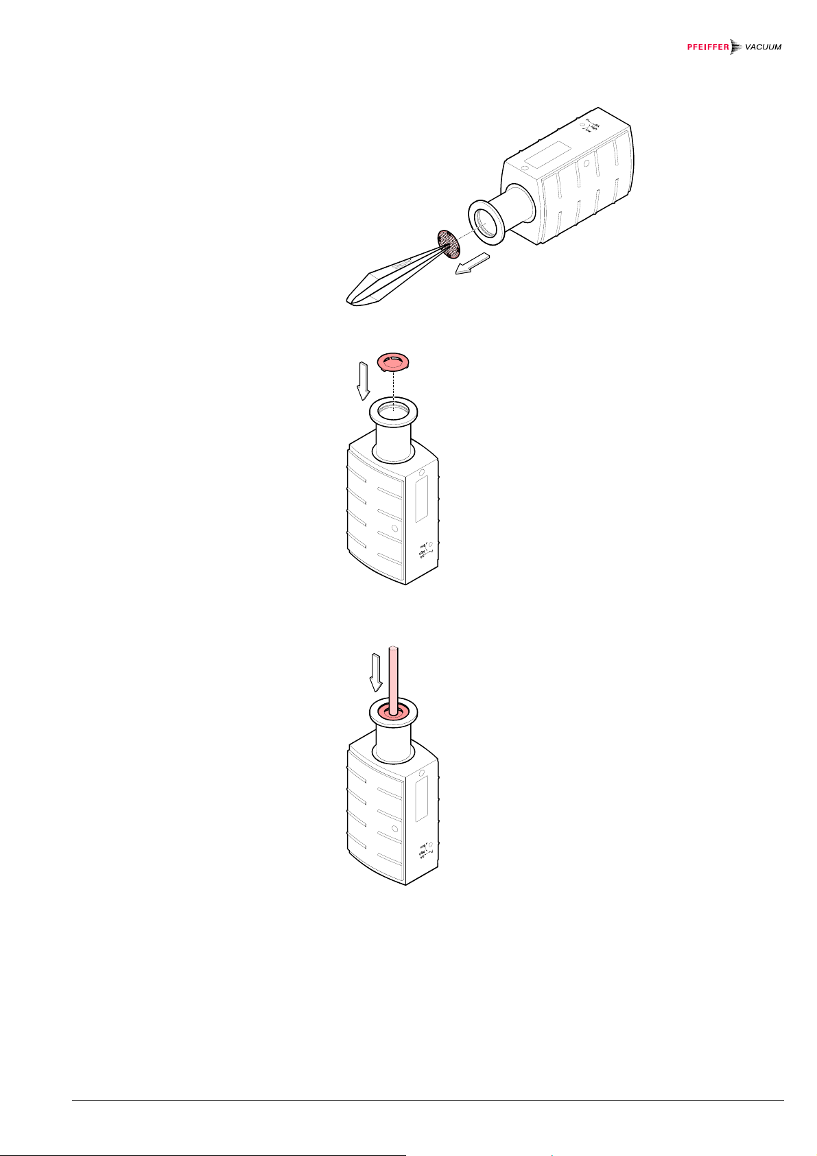
Procedure
a) Carefully remove the grid with pointed tweezers.
b) Carefully place the baffle onto the sensor opening.
c) With a stick carefully press the baffle down in the middle until it catches in the
sensor opening.
BG 5171 BEN / B (2017-02) PBR 260.oi 21

5.5 Replacing the Baffle
Tools / material required
Procedure
In case of severe contamination the baffle can be replaced.
Caution
Caution: dirt sensitive area
Dirt prolongs the pumpdown process.
Always wear clean, lint-free gloves and use clean tools when working
• New baffle (→ 26)
• Screw driver No. 1
• Stick (e.g. pencil)
a) Carefully remove the baffle with the screw driver.
in this area.
b) Carefully place new baffle onto the sensor opening.
c) With a stick carefully press the baffle down in the middle until it catches in the
sensor opening.
22
BG 5171 BEN / B (2017-02) PBR 260

5.6 Replacing the Sensor
Tools / material required
Procedure
5.7 What to Do in Case of
Problems
Replacement is necessary, when
• the sensor is severely contaminated
• the sensor is faulty, e.g. filament broken.
Gauge failures due to contamination or wear and tear, as well as
expendable parts (e.g. filament), are not covered by the warranty.
• Allen wrench AF 2.5
• Spare sensor (→ 26)
a) Deinstall the gauge (→ 24).
b) Remove the electronics unit from the faulty sensor and mount it on the new
sensor (→ 10).
c) Mount the gauge (→ 9).
d) Adjust the gauge (→ 19).
Problem Possible cause Correction
No measuring signal No supply voltage Turn on the power supply
Connection cable defec-
Check connection cable
tive or not correctly
plugged in
Measuring signal 0.3 V Hot cathode error
Gauge in an undefined
condition
Turn gauge off and on
again (reset)
Replace sensor (→ 23)
(sensor faulty)
Measuring signal 0.5 V Pirani error
Replace sensor (→ 23)
(sensor faulty)
Electronics unit not
Check connection
correctly mounted on
sensor
Gauge does not switch
over to BA at low pres-
Pirani zero point out of
tolerance
Carry out a zero point
adjustment (→ 19)
sures
In case of an error, it may be helpful to first turn the voltage supply off and
on again after 5 s.
BG 5171 BEN / B (2017-02) PBR 260.oi 23

6 Deinstallation
Procedure
DANGER
DANGER: contaminated parts
Contaminated parts can be detrimental to health.
Before beginning to work, find out whether any parts are contaminated. Adhere to the relevant regulations and take the necessary
precautions when handling contaminated parts.
Caution
Caution: vacuum component
Dirt and damages impair the function of the vacuum component.
When handling vacuum components, take appropriate measures to
ensure cleanliness and prevent damages.
Vent the vacuum system.
Put the gauge out of operation.
Unplug the connection cable.
Remove the gauge from the vacuum system.
24
BG 5171 BEN / B (2017-02) PBR 260

Place the protective cap.
BG 5171 BEN / B (2017-02) PBR 260.oi 25

7 Returning the Product
WARNING
WARNING: forwarding contaminated products
Products returned to Pfeiffer Vacuum for service or repair should
preferably be free of harmful substances (e.g. radioactive, toxic,
caustic or microbiological).
Adhere to the forwarding regulations of all involved countries and
forwarding companies and enclose a completed declaration of con-
*)
Form under www.pfeiffer-vacuum.com
tamination
Products that are not clearly declared as "free of harmful substances" are decontaminated at the expense of the customer.
When returning a product to Pfeiffer Vacuum, put it in a tight and impact resistant
package.
*)
.
8 Options
9 Spare Parts
Ordering number
Sensor cable for connection to MaxiGauge™ measurement
and control unit
3 m
6 m
10 m
Hirschmann connection socket
GO 6 WF, 6 poles, angled, female
Extension, 100 mm
Baffle
PT 448 250-T
PT 448 251-T
PT 448 252-T
B 4707 283 MA
PT 590 300-T
PT 120 125-T
When ordering spare parts, always indicate:
• all information according to the product nameplate
• description and ordering number according to the spare parts list
Ordering number
Sensor PBR 260, flange DN 25 ISO-KF (Allen wrench included) PT 120 121-T
Sensor PBR 260, flange DN 40 ISO-KF (Allen wrench included) PT 120 122-T
Sensor PBR 260, flange DN 40 CF-R (Allen wrench included) PT 120 123-T
Electronics unit PBR 260 (Allen wrench included) PT 120 120-T
26
BG 5171 BEN / B (2017-02) PBR 260
10 Disposal
Separating the components
Contaminated components
Other components
DANGER
DANGER: contaminated parts
Contaminated parts can be detrimental to health.
Before beginning to work, find out whether any parts are contaminated. Adhere to the relevant regulations and take the necessary
precautions when handling contaminated parts.
WARNING
WARNING: substances detrimental to the environment
Electronic components must be disposed of in accordance with special
regulations.
Dispose of such products in accordance with the relevant local regu-
After disassembling the product, separate its components according to the following criteria:
Contaminated components (radioactive, toxic, caustic, or biological hazard etc.)
must be decontaminated in accordance with the relevant national regulations,
separated according to their materials, and recycled.
Such components must be separated according to their materials and recycled.
lations.
BG 5171 BEN / B (2017-02) PBR 260.oi 27
Appendix
A: Conversion Table for
Pressure Units
B: Relationship Measuring
Signal – Pessure
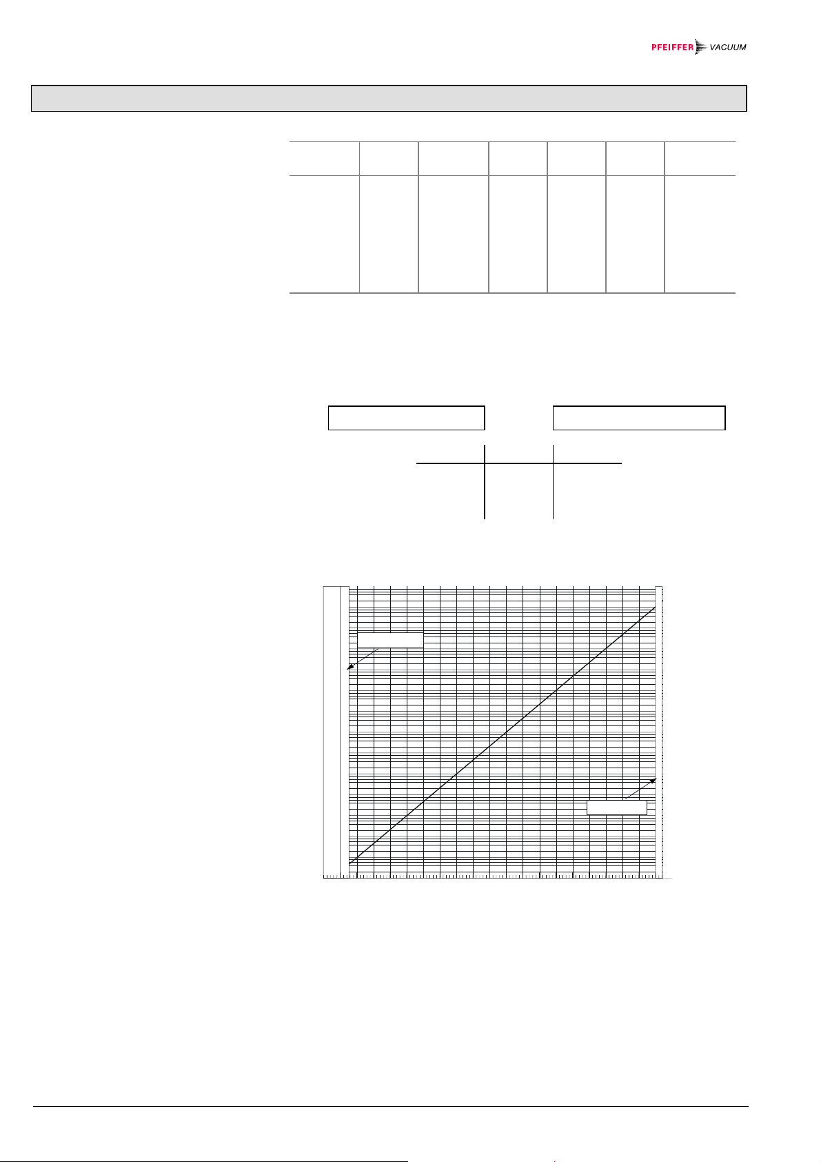
Conversion formula
Conversion curves
mbar bar Pa hPa kPa Torr
mm HG
mbar 1 1×10⁻³ 100 1 0.1 0.75
bar 1×10³ 1 1×10⁵ 1×10³ 100 750
Pa 0.01 1×10⁻⁵ 1 0.01 1×10⁻³ 7.5×10⁻³
hPa 1 1×10⁻³ 100 1 0.1 0.75
kPa 10 0.01 1×10³ 10 1 7.5
Torr
1.332 1.332×10-3133.32 1.3332 0.1332 1
mm HG
1 Pa = 1 N/m2
p = 10
(U-7.75)/0.75+c
U = 0.75×(logp-c)+7.75
U p c
[V] [hPa] 0
[V] [Pa] 2
[V] [Torr] -0.125
Pressure p [hPa]
1E+04
1E+03
1E+02
1E+01
1E+00
1E–01
1E–02
1E–03
1E–04
1E–05
1E–06
1E–07
1E–08
1E–09
1E–10
0.00.0 1.0 2.0 3.0 4.0 5.0 6.0 7.0 8.0 9.0 10.0
underrange
Sensor error
Measuring signal U[V]
overrange
28
BG 5171 BEN / B (2017-02) PBR 260
Conversion table
C: Gas Type Dependence
Below 10-3 hPa
(Hot cathode range)
Measuring signal U
[V]
[hPa]
Pressure p
[Torr]
[Pa]
<0.5 Sensor error
>0.50 … <0.774 underrange
0.774 5×10
-10
3.75×10
1.00 1×10⁻⁹ 7.5×10
-10
5×10⁻⁸
-10
1×10⁻⁷
1.75 1×10⁻⁸ 7.5×10⁻⁹ 1×10⁻⁶
2.5 1×10⁻⁷ 7.5×10⁻⁸ 1×10⁻⁵
3.25 1×10⁻⁶ 7.5×10⁻⁷ 1×10⁻⁴
4.00 1×10⁻⁵ 7.5×10⁻⁶ 1×10⁻³
4.75 1×10⁻⁴ 7.5×10⁻⁵ 1×10⁻²
5.50 1×10⁻³ 7.5×10⁻⁴ 1×10⁻¹
6.25 1×10⁻² 7.5×10⁻³ 1×100
7.00 1×10⁻¹ 7.5×10⁻² 1×101
7.75 1×100 7.5×10⁻¹ 1×10²
8.50 1×101 7.5×100 1×10³
9.25 1×10² 7.5×101 1×10⁴
10.00 1×10³ 7.5×10² 1×10⁵
>10.00 … 10.20 V overrange
For gases other than air the pressure can be determined by means of a simple
conversion formula:
p
= K × indicated pressure
eff
where Gas type K
Air (N2, O2) 1.0
Xe 0.4
Kr 0.5
Ar 0.8
H
2.4
2
Ne 4.1
He 5.9
These conversion factors are mean values.
BG 5171 BEN / B (2017-02) PBR 260.oi 29

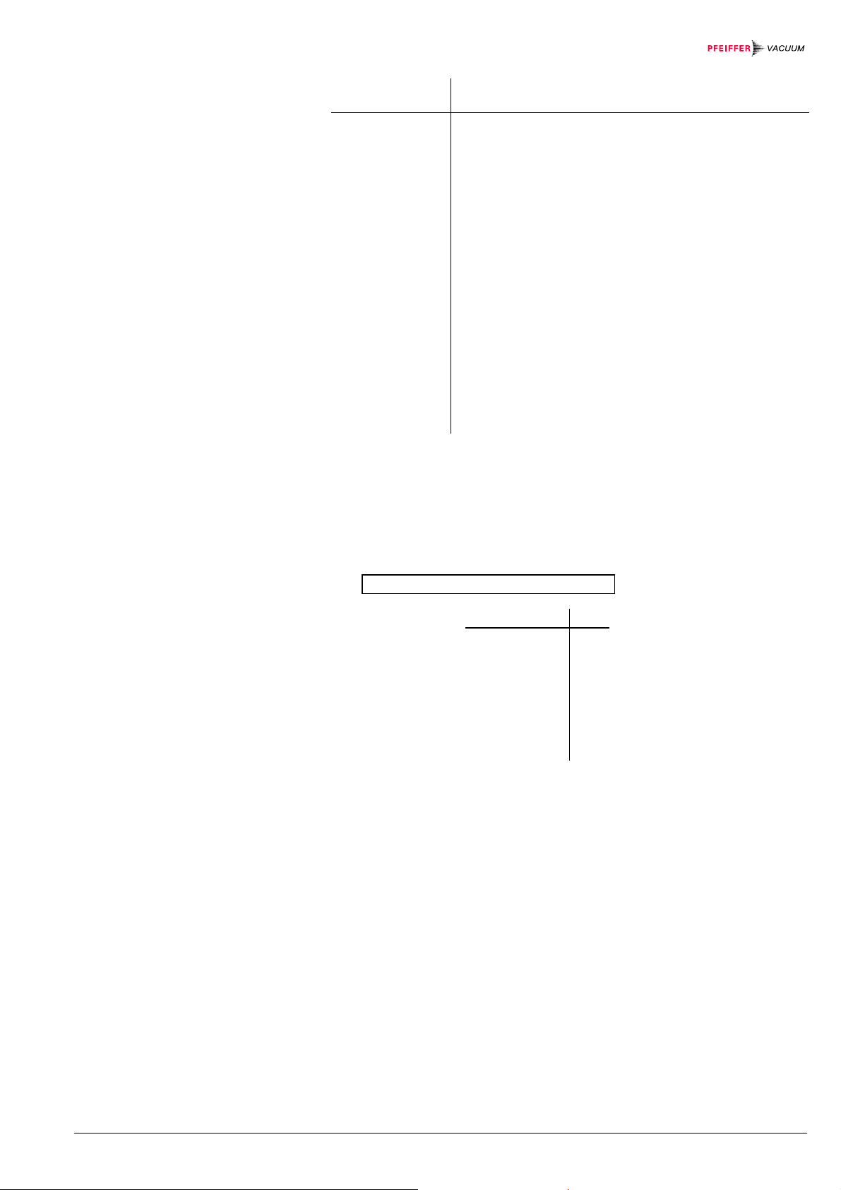
Above 10–2 hPa
(Pirani range)
p (hPa)
2
10
8
6
4
2
1
10
8
6
4
2
0
10
8
6
4
2
–1
10
8
6
4
2
Water vapor
–2
10
–3
10
24
Indication range
above 10
–2
10
6
8
24
H2He Ne
-2
hPa
–1
10
68
2468246824
0
10
Air
N
2
O
2
CO
CO
2
Ar
Freon 12
Kr
Xe
1
10
p
eff
68
(hPa)
2
10
A mixture of gases and vapors is often involved. In this case, accurate
determination is only possible with a partial-pressure measuring instrument.
Caution
30
BG 5171 BEN / B (2017-02) PBR 260

Notes
BG 5171 BEN / B (2017-02) PBR 260.oi 31

VACUUM SOLUTIONS FROM A SINGLE SOURCE
Pfeiffer Vacuum stands for innovative and custom vacuum solutions worldwide,
technological perfection, competent advice and reliable service.
COMPLETE RANGE OF PRODUCTS
From a single component to complex systems:
We are the only supplier of vacuum technology that provides a complete product portfolio.
COMPETENCE IN THEORY AND PRACTICE
Benefit from our know-how and our portfolio of training opportunities!
We can support you with your plant layout and provide first-class on-site-service worldwide.
Are you looking for a
perfect vacuum solution?
Please contact us:
Pfeiffer Vacuum GmbH
Headquarters ● Germany
T +49 6441 802-0
info@pfeiffer-vacuum.de
www.pfeiffer-vacuum.com
bg5171ben/ b
 Loading...