

OPERATING INSTRUCTIONS
MPT 200
Digital Pirani/Cold Cathode gauge
EN
Translation of the original instructions
PG 0025 BEN/C (1902)

Table of contents
Table of contents
1 About this manual. . . . . . . . . . . . . . . . . . . . . . . . . . . . . . . . . . . . . . . . . . . . . . . 3
2 Safety . . . . . . . . . . . . . . . . . . . . . . . . . . . . . . . . . . . . . . . . . . . . . . . . . . . . . . . . . 4
3 Product description. . . . . . . . . . . . . . . . . . . . . . . . . . . . . . . . . . . . . . . . . . . . . . 6
4 Transport and storage. . . . . . . . . . . . . . . . . . . . . . . . . . . . . . . . . . . . . . . . . . . . 7
5 Installation . . . . . . . . . . . . . . . . . . . . . . . . . . . . . . . . . . . . . . . . . . . . . . . . . . . . . 8
6 Operation . . . . . . . . . . . . . . . . . . . . . . . . . . . . . . . . . . . . . . . . . . . . . . . . . . . . . 11
7 Maintenance. . . . . . . . . . . . . . . . . . . . . . . . . . . . . . . . . . . . . . . . . . . . . . . . . . . 18
8 Disposal . . . . . . . . . . . . . . . . . . . . . . . . . . . . . . . . . . . . . . . . . . . . . . . . . . . . . . 19
9 Malfunctions . . . . . . . . . . . . . . . . . . . . . . . . . . . . . . . . . . . . . . . . . . . . . . . . . . 20
10 Service . . . . . . . . . . . . . . . . . . . . . . . . . . . . . . . . . . . . . . . . . . . . . . . . . . . . . . . 21
11 Accessories . . . . . . . . . . . . . . . . . . . . . . . . . . . . . . . . . . . . . . . . . . . . . . . . . . . 22
12 Spare parts. . . . . . . . . . . . . . . . . . . . . . . . . . . . . . . . . . . . . . . . . . . . . . . . . . . . 22
13 Technical data and dimensions . . . . . . . . . . . . . . . . . . . . . . . . . . . . . . . . . . . 23
1.1 Validity. . . . . . . . . . . . . . . . . . . . . . . . . . . . . . . . . . . . . . . . . . . . . . . . . . . . . 3
1.2 Conventions . . . . . . . . . . . . . . . . . . . . . . . . . . . . . . . . . . . . . . . . . . . . . . . . 3
2.1 Safety precautions . . . . . . . . . . . . . . . . . . . . . . . . . . . . . . . . . . . . . . . . . . . 4
2.2 Proper use . . . . . . . . . . . . . . . . . . . . . . . . . . . . . . . . . . . . . . . . . . . . . . . . . 5
2.3 Improper use. . . . . . . . . . . . . . . . . . . . . . . . . . . . . . . . . . . . . . . . . . . . . . . . 5
3.1 Product identification. . . . . . . . . . . . . . . . . . . . . . . . . . . . . . . . . . . . . . . . . . 6
3.2 Function . . . . . . . . . . . . . . . . . . . . . . . . . . . . . . . . . . . . . . . . . . . . . . . . . . . 6
3.3 Range of application . . . . . . . . . . . . . . . . . . . . . . . . . . . . . . . . . . . . . . . . . . 7
5.1 Vacuum connection. . . . . . . . . . . . . . . . . . . . . . . . . . . . . . . . . . . . . . . . . . . 8
5.2 Electrical connection . . . . . . . . . . . . . . . . . . . . . . . . . . . . . . . . . . . . . . . . . . 9
6.1 Before switching on. . . . . . . . . . . . . . . . . . . . . . . . . . . . . . . . . . . . . . . . . . 11
6.2 Bakeout. . . . . . . . . . . . . . . . . . . . . . . . . . . . . . . . . . . . . . . . . . . . . . . . . . . 11
6.3 Switching on/off the cold cathode sensor . . . . . . . . . . . . . . . . . . . . . . . . . 12
6.4 Selecting switching range . . . . . . . . . . . . . . . . . . . . . . . . . . . . . . . . . . . . . 13
6.5 Configuring the data exchange . . . . . . . . . . . . . . . . . . . . . . . . . . . . . . . . . 14
6.6 Pfeiffer Vacuum Protocol for "RS-485" . . . . . . . . . . . . . . . . . . . . . . . . . . . 16
6.7 Adjusting the gauge . . . . . . . . . . . . . . . . . . . . . . . . . . . . . . . . . . . . . . . . . 17
7.1 Replacing the sensor head . . . . . . . . . . . . . . . . . . . . . . . . . . . . . . . . . . . . 19
9.1 Rectifying malfunctions . . . . . . . . . . . . . . . . . . . . . . . . . . . . . . . . . . . . . . . 20
13.1 General . . . . . . . . . . . . . . . . . . . . . . . . . . . . . . . . . . . . . . . . . . . . . . . . . . . 23
13.2 Technical data. . . . . . . . . . . . . . . . . . . . . . . . . . . . . . . . . . . . . . . . . . . . . . 23
13.3 Dimensions . . . . . . . . . . . . . . . . . . . . . . . . . . . . . . . . . . . . . . . . . . . . . . . . 24
13.4 Gas correction factor. . . . . . . . . . . . . . . . . . . . . . . . . . . . . . . . . . . . . . . . . 26
Declaration of conformity. . . . . . . . . . . . . . . . . . . . . . . . . . . . . . . . . . . . . . . . 27
2
1 About this manual
1.1 Validity
This operating manual is for customers of Pfeiffer Vacuum. It describes the functioning
of the designated product and provides the most important information for safe use of
the unit. The description follows applicable EU guidelines. All information provided in this
operating manual refers to the current state of the product's development. The documentation remains valid as long as the customer does not make any changes to the product.
Up-to-date operating instructions can also be downloaded from
www.pfeiffer-vacuum.com.
Applicable documents
1.2 Conventions
MPT 200 Operating instructions
Declaration of Conformity Part of this document
Operating instructions for accessories (order-specifically) see section "accessories"*
*also available via www.pfeiffer-vacuum.com
About this manual
Safety instructions The safety instructions in Pfeiffer Vacuum operating instructions are the result of risk
evaluations and hazard analyses and are oriented on international certification standards as specified by UL, CSA, ANSI Z-535, SEMI S1, ISO 3864 and DIN 4844. In this
document, the following hazard levels and information are considered:
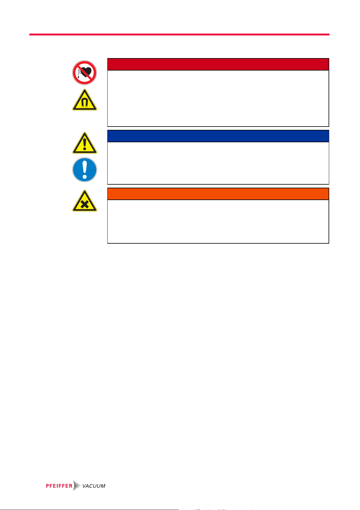
DANGER
Imminent danger
Indicates an imminent hazardous situation that will result in death or serious injury.
WARNING
Possibly imminent danger
Indicates an imminent hazardous situation that can result in death or serious injury.
CAUTION
Possibly imminent danger
Indicates an imminent hazardous situation that can result in minor or moderate injury.
NOTICE
Command or note
Command to perform an action or information about properties, the disregarding of
which may result in damage to the product.
Pictographs
Prohibition of an action to avoid any risk of accidents, the disregarding
of which may result in serious accidents
Warning of a displayed source of danger in connection with operation of
the unit or equipment
3
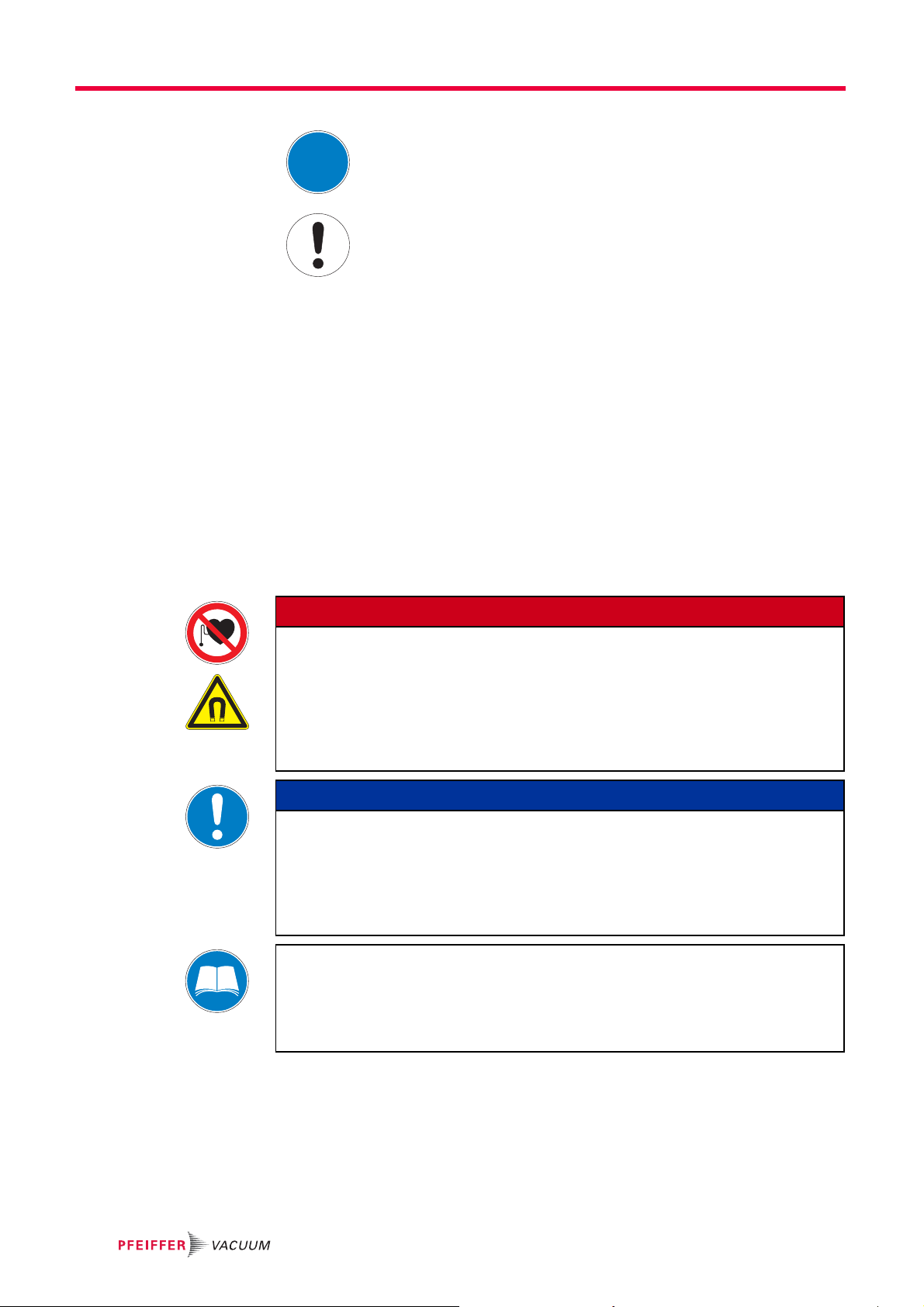
Safety
Command to perform an action or task associated with a source of danger, the disregarding of which may result in serious accidents
Important information about the product or this document
Instructions in the
Work instruction: here you have to do something.
text
Abbreviations MPT: Digital Pirani/Cold Cathode gauge
CC sensor: Cold cathode sensor
2Safety
2.1 Safety precautions
DANGER
Strong magnetic field in the vicinity of the sensor head!
Danger of death for persons with cardiac pacemakers when the magnetic unit is disassembled.
Maintenance personnel with active body aids (e.g. cardiac pacemakers) should
maintain a safe distance of at least 10 cm from the magnetic unit of the transmitter.
Disassembled magnetic unit must be kept away from computers, data storage media
and other electronic components.
NOTICE
EC conformity
The manufacturer's declaration of conformity becomes invalid if the operator modifies
the original product or installs additional components.
Following installation into a plant and before commissioning, the operator must check
the entire system for compliance with the valid EU directives and reassess it accordingly.
Duty to inform
Each person involved in the installation or operation of the unit must read and observe
the safety-related parts of these operating instuctions.
The operator is obligated to make operating personnel aware of dangers originating
from the unit or the entire system.
The gauge MPT 200 has been tested and accepted in compliance with EN 61010/VDE
0411 “Safety Equipment for Electrical Components”.
● Observe the safety and accident prevention regulations.
● Check regularly that all safety precautions are being complied with.
● The unit has been accredited with protection class IP 54. Take necessary measures
when installing into ambient conditions, which afford other protection classes.
● Consider possible reactions between the materials and the process media.
4

2.2 Proper use
2.3 Improper use
Safety
● Consider possible reactions of the process media due to the heat generated by the
product.
● Do not modify or alter the unit yourself.
● Note the shipping instructions, when returning the unit.
● Inform yourself about a possible contamination before starting work.
● Adhere to the relevant regulations and take the necessary precautions, when handling
contaminated parts.
● Communicate the safety instructions to other users.
● Only use the MPT 200 digital gauge for measuring total pressures in the
● Only use the gauge for air, inert gases and gas mixtures outside their explosion limits.
Improper use will cause all claims for liability and warranties to be forfeited. Improper use
is defined as usage for purposes deviating from those mentioned above, especially:
● connection to pumps or units which are not suitable for this purpose according to their
● connection to units which have exposed voltage-carrying parts
● operation of the devices in areas with ionizing radiation
-9
5 x 10
operating instructions
... 1000 hPa range.
5
Product description
D-35641 Asslar
Mod.: CPT 100
Range: 2000 - 1 mb ar
Mod.-No.: PT R31 130
Ser.-No.: 42000618
Made in
Germany
2012/03
1
2
S
RS-485
3
1
5
13
15
9
11
7
device status
RS485
adr
3 Product description
The digital transmitter MPT 200 consists of a cold cathode sensor and a Pirani sensor,
whose measurement principle is based on the pressure-dependent thermal conductivity
of gases. Sensor head and associated electronics are installed in a compact housing.
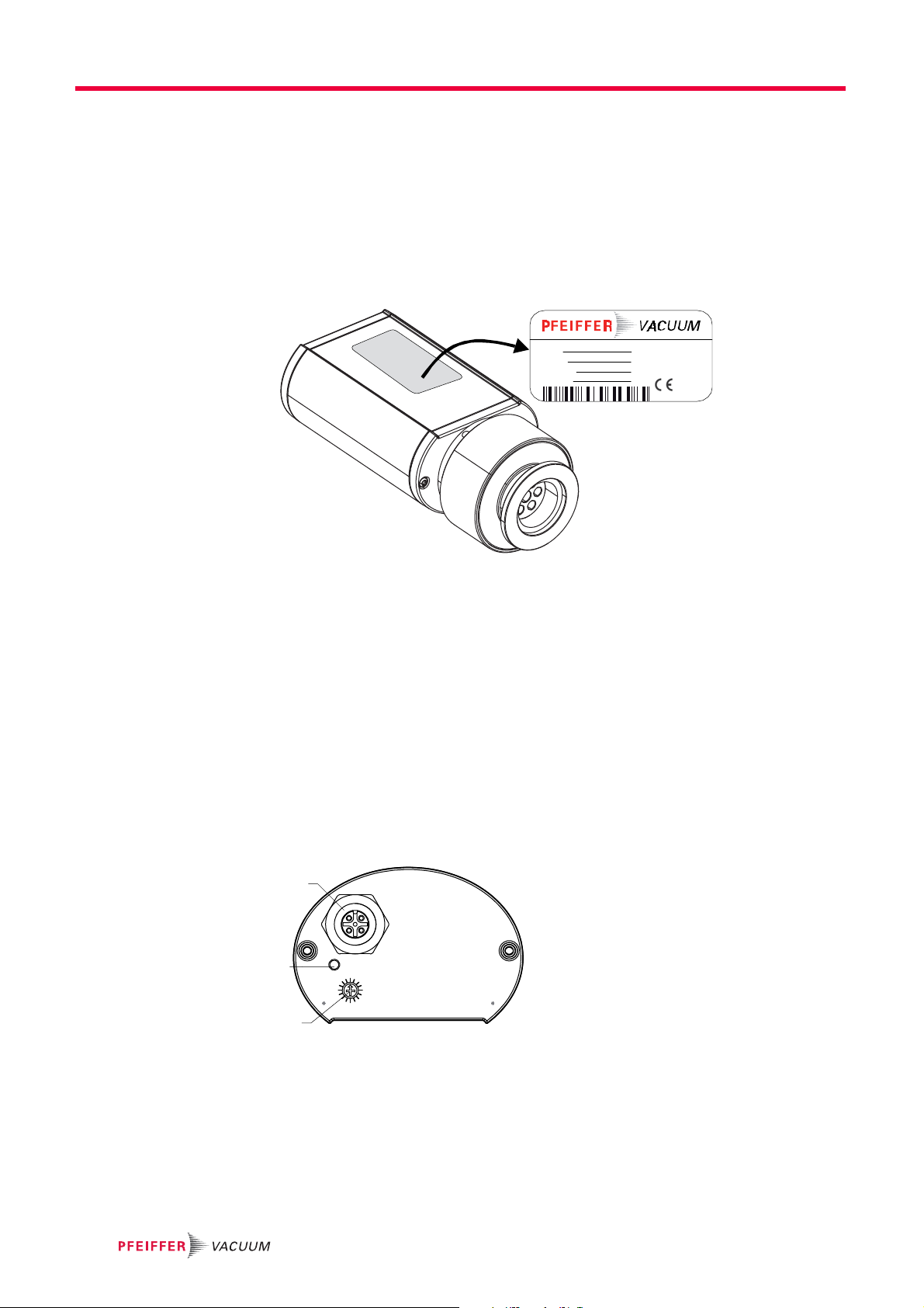
3.1 Product identification
To correctly identify the product when communicating with Pfeiffer Vacuum, always have
the information from the rating plate available.
Fig. 1: Product identification on the rating plate
Scope of delivery The following positions are included in the delivery consignment:
– MPT 200
– Protective cover
– Operating instructions
3.2 Function
The gauge can be operated in conjunction with the DigiLine Controller and the measuring software DokuStar (please see "Accessories") on a PC or with customized, digital signal evaluation.
The gauge responds to measurement value queries, type queries and setting commands.
1 RS-485 interface
2Status LED
S Address selector switch (pos. 1-16), ad-
dress 1 --> default
Fig. 2: DigiLine MPT 200 in standard version
6

3.3 Range of application
The unit MPT 200 must be installed and operated in the following ambient conditions:
Installation location weather protected (indoor)
Protection class IP 54
Installation altitude max. 2000 m
Ambient temperature +5°C to +60°C
Relative humidity 5 ... 85 %, non-condensing
Atmospheric pressure 860 hPa - 1060 hPa
4 Transport and storage
Units without external protection must not come into contact with electrostatically chargeable materials and must not be moved within electrical or magnetic fields.
In rooms with moist or aggressive atmospheres, the unit must be airproof shrink-
wrapped in a plastic bag together with a bag of desiccant.
Keep the original protective covers.
Transport and storage
7

Installation
5 Installation
5.1 Vacuum connection
NOTICE
Vacuum component
Dirt and damage impair the function of the vacuum component.
When handling vacuum components, ensure that they are kept clean and are protect-
ed against damage.
Ensure that the connection flange is clean, dry and free of grease.
CAUTION
Excess pressure in the vacuum system 1500 to 4000 hPa
Damage to health through emission of process media, because elastomer washers
cannot withstand the pressure.
Use sealing rings with an outer centering ring.
Mounting orientation The installation position can be freely selected. The preferred position is a horizontal to
vertical position so that condensate and particles do not penetrate the measurement
chamber.
Connecting the
gauge
CAUTION
Excess pressure in the vacuum system > 1000 hPa
Danger of injuries by inadvertent opening of elements under stress due to parts flying
around.
Only use stressed elements, which can be opened and closed with appropriate tools
(e.g. strap retainer-tension ring).
Remove the protective cover, which is required during maintenance work.
Make the flange connection.
– When making a CF flange connection, it can be advantageous to temporarily re-
move the magnet unit.
8

5.2 Electrical connection
12
34
5
USB
RS-485
set
DPG 202
V
A
UU
M
C
12 12
Damage to the product
Only connect cables when de-energized.
Never establish a connection using a live cable.
Communication is effected, depending on the position of the address selector switch at
the gauge (address settable from 1–16), via Serial Interface RS-485.
Setting the address
selection switch
device status
RS-485
adr
Fig. 3: Setting the address selection switch
Remove the rubber plug (not shown in the illustration) from the address selector
switch, and set the required address according to the relevant connection situation.
Reinsert the rubber plug.
RS-485
NOTICE
RS-485
adr
13
15
Installation
1
3
5
7
11
9
S
RS-485
Connecting the
gauge to the DPG 202
controller
M12 socket with screw coupling for the connection of a Pfeiffer Vacuum control unit or a
PC. The use of a Y-connector enables the series connection in a bus system.
Pin Assignment
1 RS-485: D+
2+24 V
3GND
4 RS-485: D5 not connected
Up to 2 gauges can be connected to the DPG 202 controller.
Fig. 4: Connections diagram gauge/DPG 202
Set the relevant address at the address selector switch S.
Connect the gauge to the control unit using the connection cable.
Switch on the control unit.
9

Installation
Connecting the
gauge to the USB/RS485 converter
24 V DC
12 12
Fig. 5: Connections diagram gauge - USB/RS-485 converter
USB/RS-485
Converter
Set the relevant address at the address selector switch S.
Connect the gauge to the USB/RS-485 converter using the connection cable.
Connect the gauge to the power supply.
10
6Operation
6.1 Before switching on
After switching on the power supply, the connected gauge is ready for operation. It is advisable to wait for a stabilization period of 5-10 minutes before measurement. Operate
the gauge during the measurement continuously independent of the applied pressure.
The measured pressure will depend on the type of gas. A suitable gas-type correction
factor for Pirani or cold cathode components can be set in the transmitter for the pressure
range below 0.1 hPa to adjust to different gases. The gas-type correction factor is factory
set for air and N
Operation display via
LED
Status within 1s Meaning
off no or insufficient power supply
green on valid measurement at two-component gauges, sensor component for
green flashing, (1 Hz) Sensor component for high pressure range is activ. Only valid for two-
yellow on Unit function is O.K., but due to internal operations (e. g. during ad-
red on Software or unit malfunction
green/yellow/red off (1 s) one-off: LED test after reset
red/green flashing, (1 Hz) Software update in process
at 1.00.
2
Operation
low pressure range is activ)
component gauges
justment) no valid measuring values will be displayed temporarily
Measuring range: overrange / underrange
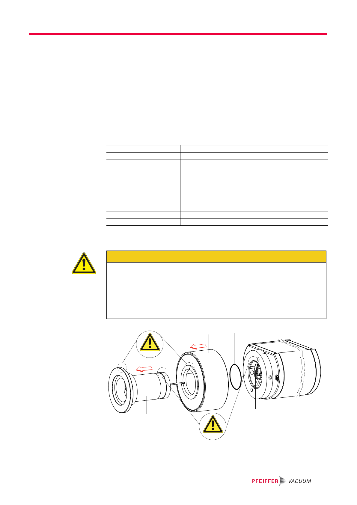
6.2 Bakeout
CAUTION
Excessive bakeout temperature!
Danger of damage to the electronics and the magnetic unit if applicable!
For baking temperatures > 60°C, always remove the electronics and magnetic unit
from sensor head 5 and only bake out flange.
The housing flange 5a must not be thermally isolated. During baking it needs to be
cooled by natural convection of ambient air.
Pay attention to the the component assignments, do not interchange.
6
7
9
8
5
Fig. 6: Disassembling sensor head and magnet unit
Loosen both set screws 9.
Pull off sensor head 5 and magnet unit 6 from the electronic 8.
11

Operation
Remove the magnet unit 6 from the sensor head 5, pay attention to O-ring 7.
Bake out sensor head 5, pay attention to max. bakeout temperatur (180 °C) at the
flange.
Adjust the gauge.
6.3 Switching on/off the cold cathode sensor
With this transmitter the CC sensor can be switched on/off to suit process requirements.This is achieved using measuring devices via the PC software Dokustar (≥ V 4.00)
or can be customized in accordance with the communication instructions.
When the power supply is switched on, the "sensor" variable is set to "On", (default setting), i.e. the MPT 100 is operating in normal mode. Status changes of this variable during operation are stored only temporarily. The status of the "sensor" variable can be altered at any time and remains stored until the power supply is switched off.
Switch on/off conditions
Status of the
CC sensor
Switched on "On" - no effect
Switched off "On" P
Switched off "Off" P
Switched on "Off" - is switched off
Switched off "On" P
1
The threshold values Px depend on the selected SwMode and amount 2.1 · 10-3 and respectively
1.0 · 10-3hPa (see also “Selecting switching ranges”).
2
The Pirani pressure value is displayed until this timer expires. If "ur" is output as the Pirani value
prior to the "On" command, output 1·10
display could be interpreted as CC under range during the timer runtime). Once "Switching on Timer" has expired, the combined value from Pirani and the CC sensor is output again.
Control command
with [P: 041]
Pirani pressure Pp
1
actual
x
x
x
-4
hPa is set during the timer runtime (otherwise, the "ur"
Effect on CC sensor
is switched on when Pp<P
remains switched off when Pp<P
is switched on and the "Switching on
timer" is started.
2
x
x
Switching on/off the CC sensor using controller
See Operating Instructions for the respective control unit for switching on/off the sen-
sor components.
Switching on/off the CC sensor for communication via RS-485-interface
Switch on CC sensor by sending [P:041] with value "1".
Switch off CC sensor by sending [P:041] with value "0".
12

6.4 Selecting switching range
Depending on the application the MPT 200 transmitter enables to adjust the switching
range between Pirani and cold cathode (CC) sensors to avoid
– the set value for pressure control is in the switching range or,
– in coating applications, the cold cathode being switched on and contaminated prema-
turely by the self-sputter effect.
Operation
Communication with con-
troller DPG 202
Communication via
serial interface
-3 -3
1·10 ... 2·10
Pirani sensorKK-(CC-) sensor
Fig. 7: Switching ranges MPT 200
mbar
SwMode
trans_LO:
switch:
Overlapping at 1–210
(CC "On" at p 2.110
CC "Off" at p 3.110
standard design)
Direct switching at 110
(CC "On" at p 110
-3
-3
-3
hPa
-3
hPa/
hPa,
-3
hPa
hPa)
Select switching ranges of the sensor components according to the operating manual
for the control unit.
Select switching range:
– trans_LO: Send [P:049] with value "1"
– switch: Send [P:049] with value "0"
13

Operation
6.5 Configuring the data exchange
Communication is effected, depending on the position of the address selector switch at
the gauge (address settable from 1–16), via Serial Interface RS-485.
● 9600 baud
● 8 data bits
● 1 stop bit
● no parity
Parameter overview
# Name Data type Handling
022 Filament selection 7 - u_short_int readable, writable X
040 Degas 6 - boolean_new readable, writable X
041 Sensor on/off 6 - boolean_new readable, writable XX
049 Switch mode 7 - u_short_int readable, writable XXX
303 Actual error code 4 - string read-only XXXXX
312 Software version 4 - string read-only XXXXX
349 Component name 4 - string read-only XXXXX
730 Pressure switch-
point 1
732 Pressure switch-
point 2
740 Pressure in [hPa] 10 - u_expo_new readable, condition-
741 Pressure set point 7 - u_short_int only writable XXXXX
742 Correction value
(Pirani)
743 Correction value
(Bayard-Alpert)
743 Correction value
(Cold cathode)
Parameters are displayed in square brackets as a three-digit number in bold font. The
designation may also be stated if necessary.
Example: [P:312] Software version
PPT 200
CPT 200
10 - u_expo_new readable, writable only analog/relay
10 - u_expo_new readable, writable only analog/relay
XXXXX
ally writable
2 - u_real readable, writable XXXX
2 - u_real readable, writable X
2 - u_real readable, writable X
RPT 200
version
version
HPT 200
MPT 200
Reading the actual
pressure value
[P:740]
14
Applied data types
Data type Description Size l1 - l0 Examp le
0 - boolean_old Boolean value (false / true) 06 000000 / 111111
1 - u_integer Positive integer number 06 000000 to 999999
2 - u_real Positive fixed point number 06 001571 equal to 15.71
4 - string String 06 TC_400
6 - boolean_new Boolean value (false / true) 01 0 / 1
7 - u_short_int Positive integer number 03 000 to 999
10 - u_expo_new Positive exponential number 06 100023
11 - string String 16 BrezelBier&Wurst
Pressure value as the value to be queried and also as equalization (see below) are transmitted by means of a string in the format "aaaabb", whereby "aaaa" is the mantissa and
"bb" the exponent with offset 20 of an exponential number. "aaaa" is therefore in the
range "1000" (for 1.000) to "9999" (for 9.999). The individual characters of the string are
the numbers "0" (ASCII 48) to "9" (ASCII 57).
+3
Example: "104223" represents 1.042 x 10
hPa, "750015" represents 7.500 x 10⁻⁵ hPa
(Depending on the gauge and its accuracy the number of significant digits in the mantissa can vary).

Operation
Reading error codes
[P:303]
Reading the component names [P:349]
Reading the software
version [P:312]
Parameter 303 transfers the actual error code of the unit. The following error codes can
occur:
Value
CPT 200
PPT 200
RPT 200
000000 XXXXXNo error
Wrn001 X Filament 1 defectve in auto-mode
Err001 XXXXXDefective gauge
Err002 XXXXXDefective memory
Err003 X Filament 1 defective
Err004 X Filament 2 defective
Err005 X Both filaments defective
HPT 200
Meaning
MPT 200
Parameter 349 contains a token of the component name:
"CPT 200"
"RPT 200"
"PPT 200"
"HPT 200"
"MPT 200"
The software version can be read from the connected device using parameter 312:
● Example: 010102
Reading/writing the
gas correction factor
[P:742]
Reading/writing the
gas correction factor
for cold cathode
[P:743]
The correction factor can be set to values in the range 0.2–8.0 :
● Example: 1,00 (written as 000100)
The correction factor can be set to values in the range 0.2–8.0 :
● Example: 1,00 (written as 000100)
15
Operation
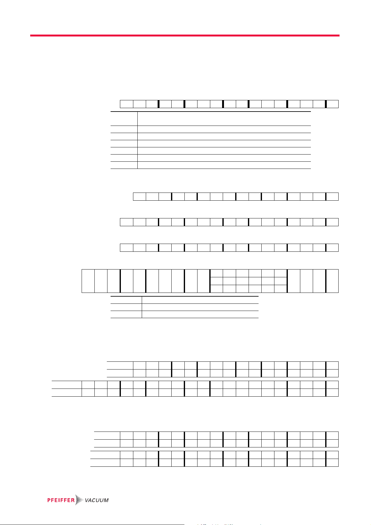
6.6 Pfeiffer Vacuum Protocol for "RS-485"
Telegram frame The telegram frame of the Pfeiffer Vacuum protocol contains only ASCII code characters
[32; 127], the exception being the end character of the message
C
. Basically, a master
R
(e.g. a PC) sends a telegram, which is answered by a slave (e.g. electronic drive
unit or gauge).
a2 a1 a0 * 0 n2 n1 n0 l1 l0 dn ... d0 c2 c1 c0
a2 - a0 Unit address for slave
– Individual address of the unit ["001";"015"]
*Action
n2 - n0 Pfeiffer Vacuum parameter numbers
l1 - l0 Data length dn ... d0
dn - d0 Data in data type concerned
c2 - c0 Checksum (sum of ASCII values of cells a2 to d0) modulo 256
C
R
Carriage return (ASCII 13)
C
R
Telegrams Data request ?
a2 a1 a0 0 0 n2 n1 n0 0 2 = ? c2 c1 c0
Control command !
a2 a1 a0 1 0 n2 n1 n0 l1 l0 dn ... d0 c2 c1 c0
Data response / control command understood
a2 a1 a0 1 0 n2 n1 n0 l1 l0 dn ... d0 c2 c1 c0
C
R
C
R
C
R
Error message
a2 a1 a0 1 0 n2 n1 n0 0 6 N O _ D E F c2 c1 c0
_RANGE
_LOGI C
NO_DEF The parameter n2 - n0 does not exist
_RANGE Data dn - d0 are outside the permitted range
_LOGIC Logic access violation
C
Telegram examples
Read actual pressure value (data query)
(Parameter [P:740], Slave device address: "001")
? 0010074002=?106
ASCII 48 48 49 48 48 55 52 48 48 50 61 63 49 48 54 13
0011074006100023025
ASCII 48 48 49 49 48 55 52 48 48 54 49 48 48 48 50 51 48 50 53 13
C
C
Activate/send parameter for atmospheric pressure (high pressure) (control command)
Atmospheric pressure adjustment (Parameter [P:741/740], Slave device address: "001")
? 0011074103001130
ASCII 48 48 49 49 48 55 52 49 48 51 48 48 49 49 51 48 13
0011074103001130
ASCII 48 48 49 49 48 55 52 49 48 51 48 48 49 49 51 48 13
C
C
R
R
R
R
R
16

Activate/send parameter for low pressure (control command)
Low pressure adjustment (Parameter [P:741/740], Slave device address: "001")
? 0011074103000129
ASCII 48 48 49 49 48 55 52 49 48 51 48 48 48 49 50 57 13
0011074103000129
ASCII 48 48 49 49 48 55 52 49 48 51 48 48 48 49 50 57 13
6.7 Adjusting the gauge
The gauge is factory-adjusted. It may be necessary to adjust the Pirani sensor in the
event of contamination, other installation positions, extreme temperature fluctuations,
ageing, etc. This is carried out using the "DokuStar" PC software via a connected control
unit or according to customer requirements following the communication instructions.
A Pirani equalization in the "ur" range (under range) will occur automatically under the
following, simultaneously applicable conditions:
– the measuring value of the CC sensor is < 5 10
– the measuring value of the Pirani sensor will remain constant for 1 minute and will not
deviate too much from the last calibrated value.
Before adjustment, the gauge should be operated at the relevant pressure for approx. 5–
10 minutes (warm-up time).
For correct zero point adjustment, the pressure in the vacuum chamber must be
p ≤ 1·10
-5
hPa.
-5
hPa.
Operation
C
R
C
R
With controller
Adjust the gauge as described in the instruction for the control unit.
DPG 202:
RS-485 Evacuate the vacuum chamber to the pressure p ≤ 1·10
Set the pressure adjusting point [P:741] to "000" for low pressure and transmit.
Send actual pressure value [P:740] with value "000000" for low pressure (corre-
sponds to p < 1·10
Vent vacuum chamber to atmospheric pressure with air or N
10 minutes.
Set the pressure adjusting point [P:741] to "001" for high pressure and transmit.
Set the actual pressure value to the atmospheric pressure ("100023" for 1000 hPa).
-1
); ==> "ur" (under range).
-5
hPa.
; afterwards wait about
2
17
Maintenance
7 Maintenance
Strong magnetic field in the vicinity of the sensor head!
Danger of death for persons with cardiac pacemakers when the magnetic unit is disassembled.
Maintenance personnel with active body aids (e.g. cardiac pacemakers) should
Disassembled magnetic unit must be kept away from computers, data storage media
Vacuum component
Dirt and damage impair the function of the vacuum component.
When handling vacuum components, ensure that they are kept clean and are protect-
Ensure that the connection flange is clean, dry and free of grease.
DANGER
maintain a safe distance of at least 10 cm from the magnetic unit of the transmitter.
and other electronic components.
NOTICE
ed against damage.
WARNING
Contamination of gauge parts possible due to the media measured!
Poisoning hazard through contact with harmful substances.
In the case of contamination, carry out appropriate safety precautions in order to pre-
vent danger to health through dangerous substances.
Decontaminate affected parts before carrying out maintenance work.
18

7.1 Replacing the sensor head
In case of a defective sensor or if the gauge cannot be adjusted after cleaning, the sensor
assembly 5 must be replaced.
Disposal
6
7
9
8
5
Fig. 8: Replacing the sensor assembly
Dismantling Turn off the vacuum pump, vent to atmospheric pressure and allow to cool.
Switch off the power supply on the control unit/power supply or disconnect the equip-
ment from the mains supply.
Loosen any connection cables.
Detach the gauge from the vacuum apparatus.
Loosen both set screws 9.
Pull off sensor head 5 and magnet unit 6 from the electronic 8.
Remove the magnet unit 6 from the sensor head 5, pay attention to O-ring 7.
Assembly Assembling is carried out in reverse order.
Install the replacement sensor assembly 5 into magnet unit 6, ensure correct orienta-
tion.
Insert O-ring 7 in groove of sensor head 5.
Insert the sensor assembly 5 into the pin pitch of the electronics 8;
– ensure correct orientation and
– ensure the O-ring 7 fits correctly 7.
Tighten both set screws 9.
Install the transmitter.
Adjust the gauge.
8 Disposal
Products or parts thereof (mechanical and electrical components, operating fluids, etc.)
may cause environmental burden.
Safely dispose of the materials according to the locally applicable regulations.
19

Malfunctions
9 Malfunctions
9.1 Rectifying malfunctions
Errors Possible cause: Remedy
Communication error: Transmitters
A too large measuring value is
emitted continuously in high
vacuum.
"ur" is emitted continuously in
high vacuum, although the pressure > 1 10
-8
hPa
● No power supply
● Incorrect address preset
● Transmitter faulty
● Adjustment required
● Transmitter faulty
● uses starting aid Change sensor.
Connect data cable or power-
pack.
Set address selector switch
correctly.
Change transmitter
Adjust transmitter.
Change sensor/gauge.
20

10 Service
Service
Malfunctions of the gauge, caused by contamination or wear, as well as wear parts (e.g.
heating filament) are not covered by warranty.
● If the sensor head is defective, it can be exchanged by the customer as described in
section maintenance
● If the electronic is defective, a repair is uneconomical and therefore not intended in
case of damage.
– Send the unit and have it replaced with a new unit
Sending of units (under warranty)
For a quick and smooth handling of the service process, Pfeiffer Vacuum recommends
the following steps:
Download the forms "Service Request" and Declaration on Contamination.
Fill out the "Service Request" form and send it by fax or e-mail to your local Pfeiffer
Vacuum service contact.
Include the confirmation on the "Service Request" from Pfeiffer Vacuum with your
shipment.
Fill out the Declaration of Contamination and include it in the shipment. This document
is mandatory to protect our service engineers.
– Fill out and send one declaration for each device.
If possible, send unit in the original packaging.
1)
In the absence or incompleteness of the "Declaration on Contamination" and/or the use
of unsuitable transport packaging, Pfeiffer Vacuum reserves the right to make a decontamination and/or to send the product back at the shipper’s expense.
Service orders
All service orders are carried out exclusively according to our repair conditions for vacuum units and components. Detailed information, addresses and forms at:
http://www.pfeiffer-vacuum.com/service/repair-services/container.action.
1)
Forms under www.pfeiffer-vacuum.com
21

Accessories
11 Accessories
Designation MPT 200
Termination resistor for RS-485 PT 348 105 -T
M12 m plug 4-pole with screw terminals RS-485 PT 348 106 -T
Power separator for RS-485 PT 348 132 -T
Adapter RS-485, M12, 4-pole - D-sub socket, 9-pole, 0.2 m PT 348 133 -T
Supply cable DigiLine, M12, 4-pole to TPS, 3 m PT 348 163 -T
Connection cable, RS-485, M12/D-sub 9-pole, 3 m PT 348 223 -T
Interface cable, M12 m straight/M12 m straight, 3 m PM 061 283 -T
Connector M12 to RS-485 PM 061 270 -X
DPG 202, Controller and power supply unit for up to 2 gauges PT G12 020
TPS 110, mains pack for wall/standard rail fitting PM 061 340 -T
TPS 111, mains pack 19" rack module 3HU PM 061 344 -T
USB converter to RS-485 interface PM 061 207 -T
DokuStar Plus software, 16 channels PT 882 501
PV TurboControl - Software for Pfeiffer Vacuum products with PV protocol PM 061 741
Centering ring with protection filter, FPM/stainless steel, DN 25 ISO-KF PF 117 225 -T
Centering ring, with protection filter, FPM/stainless steel, DN 40 ISO-KF PF 117 240 -T
Y-Connector M12 to RS-485 P 4723 010
12 Sp are parts
Pos. Description Flange No.
5 Sensor assembly DN 25 ISO-KF PT 120 210-T
5 Sensor assembly DN 40 ISO-KF PT 120 211-T
5 Sensor assembly DN 40 CF-F PT 120 212-T
22

Technical data and dimensions
13 Technical data and dimensions
13.1 General
Conversion table: pressure units
mbar bar Pa hPa kPa Torr
mbar 1 1 · 10
bar 1000 1 1 · 10
Pa 0.01 1 · 10
hPa 1 1 · 10
kPa 10 0.01 1000 10 1 7.5
Tor r
1.33 1.33 · 10
mm Hg
13.2 Technical data
Parameter MPT 200 MPT 200 MPT 200
Nominal diameter DN 25 ISO-KF DN 40 ISO-KF DN 40 CF-F
Protection category IP54 IP54 IP54
Bakeout temperature max. at the flange 180 °C 180 °C 180 °C
Seal Metal Metal Metal
Pressure max. 4000 hPa 4000 hPa 4000 hPa
Accuracy: % of measurement 1 · 10
Weight 555 g 580 g 850 g
Materials in contact with media Tungsten, stainless steel, nick-
Measurement range max. 1000 hPa 1000 hPa 1000 hPa
Measurement range min. 5 · 10
Sensor cable length max. 100 m 100 m 100 m
Method of measurement Pirani/Cold Cathode Pirani/Cold Cathode Pirani/Cold Cathode
Measuring cycle 10 ms 10 ms 10 ms
Interfaces RS-485 RS-485 RS-485
Cold cathode sensor control Cold Cathode sensor can be
Temperature: Operating +5-+60 °C +5-+60 °C +5-+60 °C
Temperature: Storage -40-+65 °C -40-+65 °C -40-+65 °C
Supply: Voltage 24 V DC 24 V DC 24 V DC
Supply: power consumption 3 W 3 W 3 W
Repeatability: % of measurement 1 · 10
-8
– 2 · 10-3 hPa: ± 25 %,
-3
2 · 10
– 10 hPa: ± 10 %, 10 –
100 hPa: ± 30 %; 100 – 1000
hPa: ± 50 %
el, molybdenum, glass
-9
hPa 5 · 10-9hPa 5 · 10-9hPa
switched on and off via interface
-8
– 1 · 10-2 hPa: ± 7 %;
-2
1 · 10
– 10 hPa: ± 2 %
-3
-5
-3
-3
1 · 10
2 · 10
100 1 0.1 0.75
5
1000 100 750
1 0.01 1 · 10
100 1 0.1 0.75
133.32 1.33 0.133 1
1 Pa = 1 N/m
-8
– 2 · 10-3 hPa: ± 25 %,
-3
– 10 hPa: ± 10 %, 10 –
2
100 hPa: ± 30 %; 100 – 1000
hPa: ± 50 %
Tungsten, stainless steel, nickel, molybdenum, glass
Cold Cathode sensor can be
switched on and off via interface
-8
– 1 · 10-2 hPa: ± 7 %; 1
1 · 10
-2
· 10
– 10 hPa: ± 2 %
-3
-8
1 · 10
– 2 · 10-3 hPa: ± 25 %,
-3
2 · 10
– 10 hPa: ± 10 %, 10
– 100 hPa: ± 30 %; 100 –
1000 hPa: ± 50 %
Tungsten, stainless steel,
nickel, molybdenum, glass
Cold Cathode sensor can be
switched on and off via interface
-8
– 1 · 10-2 hPa: ± 7 %;
1 · 10
-2
1 · 10
– 10 hPa: ± 2 %
mm Hg
7.5 · 10
-3
23

Technical data and dimensions
66 45
Ø40
Ø53
138
66
138
Ø55
45
13.3 Dimensions
Fig. 9: MPT 200, DN 25 ISO-KF
Fig. 10: MPT 200, DN 40 ISO-KF
24

155
Technical data and dimensions
66
Fig. 11: MPT 200, DN 40 CF-F
45
Ø70
25
Technical data and dimensions
1E-4
1E-3
1E-2
1E-1
1E0
1E1
1E2
1E3
1E-4 1E-3 1E-2 1E-1 1E0 1E1 1E2 1E3
H2
He
N2
Ar
Kr
displayed pressure (hPa)
real pressure (hPa)
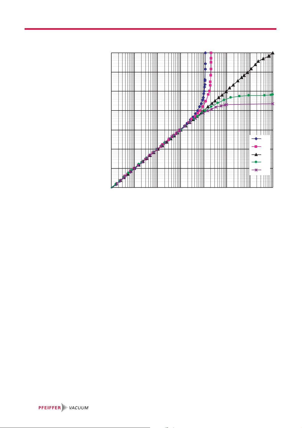
13.4 Gas correction factor
Fig. 12: Measurement curve MPT 200 (Pirani)
Pirani correction factor:
1.00
N
2
Air 1.00
H
0.58
2
He 1.02
Ar 1.59
CO
0.89
2
CF
0.93
4
Relative sensitivity in molecular range <1 · 10
-1
Cold cathode correction factor:
He 5.93
H
2.39
2
Ar 0.80
CO
0.74
2
C
0.32
3H8
Ne 3.50
Kr 0.60
Xe 0.41
R
0.28
12
CF
0.44
4
mbar
26

Declaration of conformity
We hereby declare that the product cited below satisfies all relevant provisions accord-
ing to the following EC directives:
● Electromagnetic Compatibility 2014/30/EU
● Restriction of the use of certain Hazardous Substances 2011/65/EU
DigiLine
MPT 200
Harmonised standards and national standards and specifications which have been applied:
EN 61326-1: 2013 Group 1 / Class B
EN 50581: 2012
Signature:
(Dr. Ulrich von Hülsen)
Managing Director
Pfeiffer Vacuum GmbH
Berliner Straße 43
35614 Asslar
Germany
Asslar, 2019-02-08

VACUUM SOLUTIONS FROM A SINGLE SOURCE
Pfeiffer Vacuum stands for innovative and custom vacuum solutions worldwide,
technological perfection, competent advice and reliable service.
COMPLETE RANGE OF PRODUCTS
From a single component to complex systems:
We are the only supplier of vacuum technology that provides a complete product portfolio.
COMPETENCE IN THEORY AND PRACTICE
Benefit from our know-how and our portfolio of training opportunities!
We support you with your plant layout and provide first-class on-site service worldwide.
Are you looking for a
perfect vacuum solution?
Please contact us:
www.pfeiffer-vacuum.com
Pfeiffer Vacuum GmbH
Headquarters • Germany
T +49 6441 802-0
info@pfeiffer-vacuum.de
 Loading...