

Pfeiffer Vacuum CMR 361, CMR 362, CMR 364, CMR 365, CMR 363 Operating Instructions Manual
...
A PASSION FOR PERFECTION
CMR 361 … CMR 365
Ceramic Capacitance Gauge
Operating Instructions
BG 5136 BEN / B (2013-11)
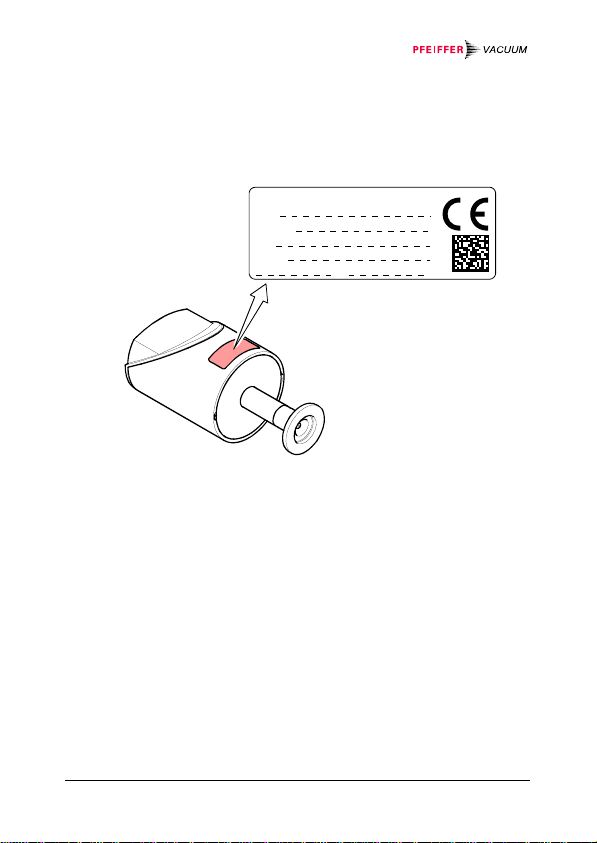
Product Identification
In all communications with Pfeiffer Vacuum, please specify the
information given on the product nameplate. For convenient reference copy that information into the space provided below.
Pfeiffer Vacuum, D-35614 Asslar
Typ:
Range:
No:
F-No:
V W
2
BG 5136 BEN / B (2013-11)

Validity
This document applies to products with the following part numbers:
Measurement range
min. (0 V) F.S. (9 V) max. (9.8 V)
Type Part number Flange [hPa]
PT R24 600 ½" tube
CMR 361
PT R24 601 DN 16 ISO-KF
PT R24 602 DN 16 CF-R
PT R24 603
8 VCR®
[Pascal]
-1
10
1
10
PT R24 610 ½" tube
CMR 362
PT R24 611 DN 16 ISO-KF
PT R24 612 DN 16 CF-R
PT R24 613
8 VCR®
10-2
10
0
PT R24 620 ½" tube
CMR 363
CMR 364
CMR 365
PT R24 621 DN 16 ISO-KF
PT R24 622 DN 16 CF-R
PT R24 623
8 VCR®
PT R24 630 ½" tube
PT R24 631 DN 16 ISO-KF
PT R24 632 DN 16 CF-R
PT R24 633
8 VCR®
PT R24 640 ½" tube
PT R24 641 DN 16 ISO-KF
PT R24 642 DN 16 CF-R
PT R24 643
8 VCR®
10-3
10
10
10
10
10
-1
-4
-2
-5
-3
The part number (No) can be taken from the product nameplate.
If not indicated otherwise in the legends, the illustrations in this
document correspond to CMR 361 gauges with the
DN 16 ISO-KF vacuum connection. They apply to other vacuum
connections by analogy.
We reserve the right to make technical changes without prior
notice. All dimensions in mm.
[hPa]
[Pascal]
1000
100'000
100
10'000
10
1'000
1
100
0.1
10
[hPa]
[Pascal]
1100
110'000
110
11'000
11
1'100
1.1
110
0.11
11
BG 5136 BEN / B (2013-11) 3

Intended Use
The Ceramic Capacitance Gauges of the CMR 36X series are
intended for absolute pressure measurement of gases in their
respective pressure ranges (→ 3).
Function
The Ceramic Capacitance Gauge consists of a capacitive sensor
element made of aluminum oxide ceramics and electronics
which convert the capacitance into a DC voltage output signal.
The output signal is linear to the measured pressure and independent of the gas type.
Trademark
VCR® Swagelok Marketing Co.
Patents
EP 1070239 B1, 1040333 B1
US Patents 6528008, 6591687, 7107855, 7140085
Scope of Delivery
1× gauge CMR 36X
1× pin for adjusting settings via buttons
1× Calibration Test Report
1× Operating Instructions German
1× Operating Instructions English
1× Operating Instructions French
4
BG 5136 BEN / B (2013-11)

Contents
Product Identification 2
Validity 3
Intended Use 4
Function 4
Trademark 4
Patents 4
Scope of Delivery 4
1
Safety 6
1.1 Symbols Used 6
1.2 Personnel Qualifications 6
1.3 General Safety Instructions 7
1.4 Liability and Warranty 7
2 Technical Data 8
3 Installation 13
3.1 Vacuum Connection 13
3.2 Power Connection 16
4 Operation 18
4.1 Displays 18
4.2 Zeroing the Gauge 18
4.2.1 <ZERO> Adjustment 19
4.3 Activating the Factory Setting (Factory Reset) 22
5 Deinstallation 23
6 Maintenance, Repair 24
7 Returning the Product 25
8 Disposal 25
Conversion Table 26
EC Declaration of Conformity 27
For cross-references within this document, the symbol (→ XY)
is used.
BG 5136 BEN / B (2013-11) 5

1 Safety
1.1 Symbols Used
DANGER
Information on preventing any kind of physical injury.
WARNING
Information on preventing extensive equipment and environmental damage.
Caution
Information on correct handling or use. Disregard can lead to
malfunctions or minor equipment damage.
Notice
1.2 Personnel Qualifications
Skilled personnel
All work described in this document may only be carried out by
persons who have suitable technical training and the necessary experience or who have been instructed by the end-user
of the product.
6
BG 5136 BEN / B (2013-11)

1.3 General Safety Instructions
• Adhere to the applicable regulations and take the necessary
precautions for the process media used.
Consider possible reactions with the product materials.
• Adhere to the applicable regulations and take the necessary
precautions for all work you are going to do and consider the
safety instructions in this document.
• Before beginning to work, find out whether any vacuum components are contaminated. Adhere to the relevant regulations
and take the necessary precautions when handling contaminated parts.
Communicate the safety instructions to all other users.
1.4 Liability and Warranty
Pfeiffer Vacuum assumes no liability and the warranty becomes
null and void if the end-user or third parties
• disregard the information in this document
• use the product in a non-conforming manner
• make any kind of interventions (modifications, alterations etc.)
on the product
• use the product with accessories not listed in the product
documentation.
The end-user assumes the responsibility in conjunction with the
process media used.
Gauge failures due to contamination or wear and tear are not
covered by the warranty.
BG 5136 BEN / B (2013-11) 7

2 Technical Data
Measurement range
Accuracy
Temperature effect on zero
Temperature effect on span
Resolution
Gas type dependence none
Output signal analog
(measuring signal)
Error signal <0.4 V (no supply,
Output impedance
Loaded impedance
Response time
1)
PT R24 600 … PT R24 633
PT R24 640 … PT R24 643
PT R24 600 … PT R24 623
PT R24 630 … PT R24 633
PT R24 640 … PT R24 643
PT R24 600 … PT R24 633
PT R24 640 … PT R24 643
Voltage range 0 … +11 V
Measuring range +1.0 … +9.8 V
Relationship voltage-pressure linear
PT R24 600 … PT R24 633
PT R24 640 … PT R24 640
→ "Validity"
0.20% of reading
0.50% of reading
0.0050% F.S./ °C
0.015% F.S./ °C
0.020% F.S./ °C
0.01% of reading / °C
0.03% of reading / °C
0.003% F.S.
sensor error)
>9.8 V ("overrange")
<10 Ω (short-circuit proof)
10 kΩ
30 ms
130 ms
1)
Non-linearity, hysteresis, repeatability in the calibrated range at
25 °C ambient operating temperature without temperature effects
after operation of 2 h.
8
BG 5136 BEN / B (2013-11)

Gauge identification Resistance 13.2 kΩ refer-
enced to supply common
Supply
DANGER
The gauge may only be connected to power supplies, instruments or control devices that conform
to the requirements of a grounded protective extralow voltage (SELV). The connection to the gauge
Supply voltage
has to be fused.
at the gauge
ripple
+14 … +30 VDC
≤1 V
pp
Current consumption <500 mA
(max. starting current)
Power consumption
(depending on supply voltage) ≤1 W
Internal fuse 1 AT (slow), automatic reset
(Polyfuse)
The gauge is protected against reverse polarity of the supply
voltage.
Electrical connection Hirschmann compact
connector, type GO 6,
6 poles, pins
Sensor cable 5 poles plus shielding
Cable length ≤120 m (0.25 mm² conductor)
For longer cables, larger conductor cross-sections are required
≤1.0 Ω).
(R
cable
Grounding concept
Vacuum flange - signal common
→ "Power Connection"
Supply common - signal common conducted separately; for dif-
ferential measurement (10 Ω)
BG 5136 BEN / B (2013-11) 9

Materials exposed to vacuum
Flange, tube
Sensor and diaphragm
Sensor–diaphragm connection
Ceramics–metal connection
Internal volume ≤3.6 cm
Admissible pressure (absolute)
PT R24 600 … PT R24 603
PT R24 610 … PT R24 633
PT R24 640 … PT R24 643
stainless steel AISI 316L
ceramics (Al
≥99.5%)
2O3
glass ceramics solder
AgTiCu hard solder, Vacon 70
(28% Ni, 23% Co, 49% Fe)
3
300 kPa
200 kPa
130 kPa
Bursting pressure (absolute) 500 kPa
Admissible temperatures
Storage
Operation
Bakeout (not in operation)
–40 °C … +65 °C
+5 °C … +50 °C
≤110 °C at the flange
Relative humidity ≤80% at temperatures
≤+31 °C decreasing to 50%
at +40°C
Use indoors only, altitude up to
2000 m NN
Type of protection IP 30
10
BG 5136 BEN / B (2013-11)
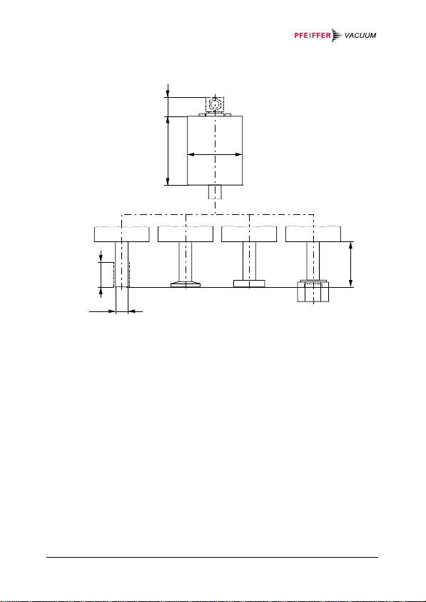
Dimensions [mm]
69 23
55
26
OD½"
DN 16 ISO-KF DN 16 CF-R
Weight ≤370 g
8 VCR
female
44
BG 5136 BEN / B (2013-11) 11

Analog Measuring Signal vs. Pressure
Pressure p [hPa]
1.1
1.0
0.9
0.8
0.7
0.6
0.5
0.4
0.3
0.2
0.1
0
F.S.
sensor error
sensor error
underrange
underrange
underrange
underrange
0.6
123456789
Measuring signal U [V]
overrange
p = (U - 1) × c (F.S.)
hPa Pa Torr
c 0.125 12.5 0.094
Example: Gauge CMR 361 with 1000 hPa F.S.
Measuring signal U
out
= 6 V
p = (6 V - 1 V) × 0.125 × 1000 hPa
= 625 hPa
overrangesensor error
overrangesensor error
overrange
9.8
100
12
BG 5136 BEN / B (2013-11)

3 Installation
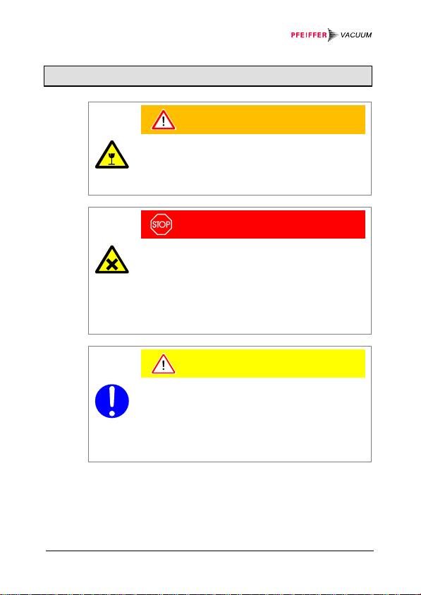
WARNING
WARNING: fragile components
The ceramic sensor may be damaged by impacts.
Do not drop the product and prevent shocks and
3.1 Vacuum Connection
impacts.
DANGER
DANGER: overpressure in the vacuum system
>100 kPa
Injury caused by released parts and harm caused
by escaping process gases can result if clamps are
opened while the vacuum system is pressurized.
Do not open any clamps while the vacuum system
is pressurized. Use the type clamps which are
suited to overpressure.
DANGER
DANGER: overpressure in the vacuum system
>250 kPa
KF flange connections with elastomer seals (e.g.
O-rings) cannot withstand such pressures. Process
media can thus leak and possibly damage your
health.
Use O-rings provided with an outer centering ring.
BG 5136 BEN / B (2013-11) 13

DANGER: protective ground
Products that are not correctly connected to ground
can be extremely hazardous in the event of a fault.
Electrically connect the gauge to the grounded
vacuum chamber. This connection must conform to
the requirements of a protective connection according to EN 61010:
• CF and VCR flanges fulfill this requirement.
• For gauges with a KF flange, use a conductive
metallic clamping ring.
• For gauges with a ½" tube, take appropriate
measures to fulfill this requirement.
Caution: vacuum component
Dirt and damages impair the function of the vac-
uum component.
When handling vacuum components, take appro-
priate measures to ensure cleanliness and prevent
damages.
DANGER
Caution
14
BG 5136 BEN / B (2013-11)

Caution
Caution: dirt sensitive area
Touching the product or parts thereof with bare
hands increases the desorption rate.
Always wear clean, lint-free gloves and use clean
tools when working in this area.
Mount the gauge so that no vibrations occur. The gauge
may be mounted in any orientation. To keep condensates and particles from getting into the measuring
chamber preferably choose a horizontal to upright position and possibly use a seal with a centering ring and
filter. If adjustment should be possible after the gauge
has been installed, be sure to install it so that the buttons can be accessed with a pin (→ 18).
Remove the protective lid and connect the product to the vacuum system.
Seal with centering ring
or
Protective lid
Seal with centering ring
and filter
Clamp
Keep the protective lid.
BG 5136 BEN / B (2013-11) 15

3.2 Power Connection
Make sure the vacuum connection is properly made
(→ 13).
DANGER
The gauge may only be connected to power supplies, instruments or control devices that conform
to the requirements of a grounded protective extralow voltage (SELV). The connection to the gauge
has to be fused.
Ground loops, differences of potential, or EMC problems
may affect the measurement signal. For optimum signal
quality, please do observe the following notes:
• Connect the cable shield to ground on one side via
the chassis ground. Do not connect the other side of
the shield.
• Connect the supply common with protective ground
directly at the power supply.
• Use differential measurement input (signal common
and supply common conducted separately).
• Potential difference between supply common and
housing ≤18 V (overvoltage protection).
16
BG 5136 BEN / B (2013-11)

If no sensor cable is available, make one according to the
following diagram.
18 V
Electrical connection
Pin 1 Identification
Pin 2 Signal output (measuring signal)
Pin 3 Signal common
Pin 4 Supply
Pin 5 Supply common
Pin 6 Screening
13K2
100nF
1MΩ
2
3
1
4
5
6
3
4
Connector,
soldering side
+
–
+
–
2
1
6
5
Connect the sensor cable to the gauge and secure it using
the lock screw.
Connect the sensor cable to the controller.
BG 5136 BEN / B (2013-11) 17

4 Operation
Put the gauge into operation.
A warm-up time of at least 15 minutes should be allowed; for
exact pressure measurements a warm-up time of at least
2 hours is required.
4.1 Displays
For factory
setting only
RUN
ZERO
LED State Meaning
<RUN>
lit Measurement mode
flashing Other mode, error,
under/overrange
4.2 Zeroing the Gauge
The gauge is factory calibrated while "standing upright"
(→ "Calibration Test Report").
We recommend performing a zero adjustment, when the
gauge is operated for the first time.
Due to long time operation or contamination, a zero drift could
occur and zero adjustment may become necessary.
For adjusting the zero, operate the gauge under the same constant ambient conditions and in the same mounting orientation
as normally.
18
BG 5136 BEN / B (2013-11)

The output signal (measuring signal) is depending on the mounting orientation. The signal difference between the vertical and
horizontal mounting orientation is:
F.S. ΔU / 90°
1000 hPa ≈2 mV
100 hPa ≈10 mV
10 hPa ≈50 mV
1 hPa ≈300 mV
0.1 hPa ≈1.8 V
If the gauge is operated via a controller, the zero of the
whole measuring system has to be adjusted on the
controller: first, adjust the zero of the gauge and then,
the zero of the controller.
4.2.1 <ZERO> Adju stme n t
Evacuate the gauge to a pressure according to the table
below:
F.S.
1100 hPa
110 hPa
11 hPa
1.1 hPa
0.11 hPa
If the final pressure in the gauge is too high for zero adjustment (>25% of the F.S.), the zero cannot be reached
and the <RUN> LED flashes. If this is the case, activate the
factory setting and adjust the zero again (→ 22).
Recommended final pressure for
zero adjustment
-2
<5
×10
hPa
-3
×10
hPa
<5
-4
×10
hPa
<5
-5
×10
hPa
<5
-6
×10
hPa
<5
<6.65
<6.65
<6.65
<6.65
<6.65
×10
×10
×10
×10
×10
0
-1
-2
-3
-4
Pa
Pa
Pa
Pa
Pa
Operate the gauge for at least 15 minutes (until the signal
is stable).
BG 5136 BEN / B (2013-11) 19

Press the <ZERO> button briefly with a pin (max.
ø1.1 mm). The zero adjustment runs automatically. The
<RUN> LED flashes until the adjustment (duration ≤8 s) is
completed.
Press the button briefly
max. ø1.1 mm
After zero adjustment the gauge automatically returns to
measurement mode. The <RUN> LED lit.
The <RUN> LED flashes if
• the signal output is negative (>22 mV) when the final pressure
has been attained
• the zero adjustment has failed.
4.2.2 <ZERO> Adjustment with Ramp Function
The ramp function allows to adjust the zero at a known reference
pressure within the measurement range of the gauge.
It also permits to adjust an offset of the characteristic curve in
order to
• compensate for the offset of the measuring system or
• obtain a slightly positive zero for a 0 … 10 V AD-converter.
20
BG 5136 BEN / B (2013-11)

The offset should not exceed 2% of the F.S. (+160 mV). At a
higher positive offset, the upper limit of the measurement range
is exceeded.
Recommended procedure for adjusting the offset of a
measuring system: → Notice 19.
Operate the gauge for at least 15 minutes (until the signal
is stable).
Push the <ZERO> button with a pin (max. ø1.1 mm) and
keep it depressed. The <RUN> LED starts flashing. After
5 s, the zero adjustment value, starting at the current output value, keeps continually changing (ramp) until the button is released or until the setting limit (max. 25% F.S.) is
reached. The corresponding output signal is delayed by
about 1 s.
Keep the button
depressed
max. ø1.1 mm
BG 5136 BEN / B (2013-11) 21

Push the <ZERO> button again:
Fine adjustment
within 0...3 s:
Change of direction
within 3...5 s:
If the <ZERO> button is released for more than 5 s, the
gauge returns to the measurement mode.
The <RUN> LED flashes if the signal output is negative.
the zero adjustment value changes
by one unit (push <ZERO> button in
intervals of 1 s)
the zero adjustment changes its
direction (the flashing frequency of
the <RUN> LED changes briefly)
4.3 Activating the Factory Setting (Factory Reset)
All user defined parameters (e.g. zero, filter) are restored to their
default values.
Loading of the default parameters is irreversible.
Loading the default parameters:
Put the gauge out of operation.
Keep the <ZERO> button depressed for at least 5 s while
the gauge is being put into operation (Power ON).
22
BG 5136 BEN / B (2013-11)
5 Deinstallation
WARNING
WARNING: fragile components
The ceramic sensor may be damaged by impacts.
Do not drop the product and prevent shocks and
impacts.
DANGER
DANGER: contaminated parts
Contaminated parts can be detrimental to health
and environment.
Before beginning to work, find out whether any
parts are contaminated. Adhere to the relevant
regulations and take the necessary precautions
when handling contaminated parts.
Caution
Caution: vacuum component
Dirt and damages impair the function of the vac-
uum component.
When handling vacuum components, take appro-
priate measures to ensure cleanliness and prevent
BG 5136 BEN / B (2013-11) 23
damages.

Caution
Caution: dirt sensitive area
Touching the product or parts thereof with bare
hands increases the desorption rate.
Always wear clean, lint-free gloves and use clean
tools when working in this area.
Vent the vacuum system.
Put the gauge out of operation.
Unfasten the lock screw and disconnect the sensor cable.
Remove the gauge from the vacuum system and install the
protective lid.
6 Maintenance, Repair
Under clean operating conditions, the product requires no maintenance.
Gauge failures due to contamination and wear and tear
are not covered by the warranty.
We recommend checking the zero at regular intervals
(→ 19).
Pfeiffer Vacuum assumes no liability and the warranty becomes
null and void if any repair work is carried out by the end-user or
third parties.
24
BG 5136 BEN / B (2013-11)

7 Returning the Product
WARNING
WARNING: forwarding contaminated products
Contaminated products (e.g. radioactive, toxic,
caustic or microbiological hazard) can be detrimental to health and environment.
Products returned to Pfeiffer Vacuum should preferably be free of harmful substances. Adhere to
the forwarding regulations of all involved countries
and forwarding companies and enclose a duly
*)
Form under www.pfeiffer-vacuum.com
completed declaration of contamination
Products that are not clearly declared as "free of harmful substances" are decontaminated at the expense of the customer.
Products not accompanied by a duly completed declaration of
contamination are returned to the sender at his own expense.
8 Disposal
DANGER
Caution: contaminated parts
Contaminated parts can be detrimental to health
and environment.
Before beginning to work, find out whether any
parts are contaminated. Adhere to the relevant
regulations and take the necessary precautions
when handling contaminated parts.
*)
.
BG 5136 BEN / B (2013-11) 25
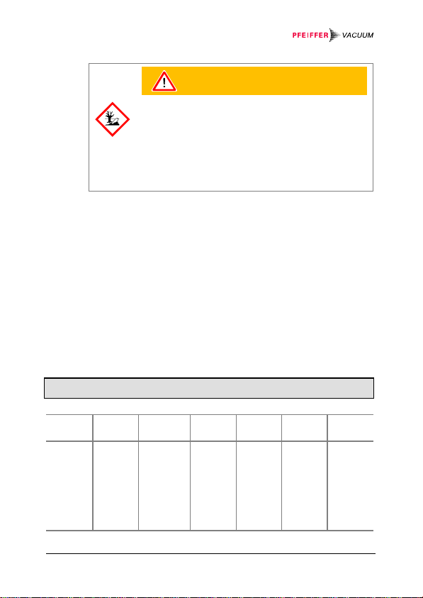
Caution: substances detrimental to the environment
Products or parts thereof (mechanical and electric
components, operating fluids etc.) can be detrimental to the environment.
Dispose of such substances in accordance with the
relevant local regulations.
Separating the components
After disassembling the product, separate its components according to the following criteria:
• Contaminated components
Contaminated components (radioactive, toxic, caustic or bio-
logical hazard etc.) must be decontaminated in accordance
with the relevant national regulations, separated according to
their materials, and disposed of.
• Other components
Such components must be separated according to their ma-
terials and recycled.
Conversion Table
mbar
bar
Pa
hPa
kPa
Torr
mm HG
26
mbar bar Pa hPa kPa Torr
1 1×10⁻³ 100 1 0.1 0.75
1×10³ 1 1×10⁵ 1×10³ 100 750
0.01 1×10⁻⁵ 1 0.01 1×10⁻³ 7.5×10⁻³
1 1×10⁻³ 100 1 0.1 0.75
10 0.01 1×10³ 10 1 7.5
1.332 1.332×10⁻³ 133.32 1.3332 0.1332 1
WARNING
1 Pa = 1 N/m2
mm HG
BG 5136 BEN / B (2013-11)

EC Declaration of Conformity
We, Pfeiffer Vacuum, hereby declare that the equipment mentioned below complies with the provisions of the Directive relating to electromagnetic compatibility 2004/108/EC and the
Directive on the restriction of the use of certain hazardous
substances in electrical and electronic equipment 2011/65/EU.
Ceramic Capacitance Gauge
CMR 361 … CMR 365
Standards
Harmonized and international/national standards and specifications:
• EN 61000-6-2:2005
• EN 61000-6-3:2007
• EN 61010-1:2010
measurement, control and laboratory use)
• EN 61326-1:2006
measurement, control and laboratory use))
Manufacturer / Signature
Pfeiffer Vacuum GmbH, Berliner Straße 43, D-35614 Asslar
9 December 2013 9 December 2013
(EMC: generic immunity standard)
(EMC: generic emission standard)
(Safety requirements for electrical equipment for
(EMC requirements for electrical equipment for
Manfred Bender
Managing director
Dr. Matthias Wiemer
Managing director
BG 5136 BEN / B (2013-11) 27

A PASSION FOR PERFECTION
Vacuum solutions
from a single source
Complete range
of products
Competence in
theory and practice
Pfeiffer Vacuum stands for innovati ve and custom
vacuum solutions worldwide, technol ogical perfection,
competent advice and reliable service.
From a single component to complex systems:
We are the only supplier of vacuum tec hnology
that provides a complete product portf olio.
Benefit from our know-how and our portfol io of training
opportunities! We can support you with your plant layout
and provide first-class on-site-service worldwide.
You are looking for a
perfect vacuum solution?
Please contact us:
Original: German BG 5136 BDE / B (2013-11)
Pfeiffer Vacuum GmbH
Headquarters ● Germany
Tel.: +49 6441 802-0
info@pfeiffer-vacuum.de
www.pfeiffer-vacuum.com
bg5136ben/b
 Loading...