


BG 5136 BEN / C
A PASSION FOR PERFECTION
EN
CMR 361 … CMR 365
Ceramic Capacitance Gauge
(2019-06)
Operating instructions

Product identification
The details on the rating plate are required when communicating
with Pfeiffer Vacuum. Therefore, you must specify these details.
2 BG 5136 BEN/C (2019-06)

Measuring range
min. (0 V)
F.S. (9 V)
max. (9.8 V)
[Pascal]
[Pascal]
[Pascal]
PT R24 600
½" tube
PT R24 601
DN 16 ISO-KF
PT R24 602
DN 16 CF-R
PT R24 603
8 VCR®
PT R24 610
½" tube
PT R24 611
DN 16 ISO-KF
PT R24 612
DN 16 CF-R
PT R24 613
8 VCR®
PT R24 620
½" tube
PT R24 621
DN 16 ISO-KF
PT R24 622
DN 16 CF-R
PT R24 623
8 VCR®
PT R24 630
½" tube
PT R24 631
DN 16 ISO-KF
PT R24 632
DN 16 CF-R
PT R24 633
8 VCR®
PT R24 640
½" tube
PT R24 641
DN 16 ISO-KF
PT R24 642
DN 16 CF-R
PT R24 643
8 VCR®
Validity
This document is applicable for products with the part numbers:
Type Part number Flange [hPa]
-1
CMR 361
CMR 362
CMR 363
CMR 364
CMR 365
10
101
10-2
100
10-3
10-1
10
10-2
10
10-3
-4
-5
The part number (P/N) can be obtained from the rating plate.
Figures with no designation relate to gauge CMR 361 with
vacuum connection DN 16 ISO-KF. These characteristics apply
for all other gauges accordingly.
We reserve the right to make technical changes without prior
notification.
All dimensions stated in mm.
[hPa]
1,000
100,000
100
10'000
10
1,000
1
100
0.1
10
[hPa]
1,100
110,000
110
11'000
11
1,100
1.1
110
0.11
11
BG 5136 BEN/C (2019-06) 3

Intended use
The Ceramic Capacitance Gauges from the CMR 36X series are
vacuum gauges and enable the measuring of absolute pressure
of gases in diverse measuring ranges (→ 3).
Function
The CMR gauge comprises a ceramic capacitive sensor element
and an electronic circuit that converts the capacity into a direct
voltage output signal.
The output signal is linear with the measured pressure and is
independent of the gas type being measured.
Type
VCR® Swagelok Marketing Co.
Patents
EP 1070239 B1, 1040333 B1
US patents 6528008, 6591687, 7107855, 7140085
Scope of delivery
1× CMR 36X gauge
1× stylus
1× calibration certificate
1× operating instructions German
1× operating instructions English
1× operating instructions French
4 BG 5136 BEN/C (2019-06)

Contents
Product identification 2
Validity 3
Intended use 4
Function 4
Type 4
Patents 4
Scope of delivery 4
1 Safety 6
1.1 Symbols used 6
1.2 Personnel qualifications 6
1.3 General safety instructions 7
1.4 Responsibilities and warranty 7
2 Technical data 8
3 Installation 13
3.1 Vacuum connection 13
3.2 Electrical connection 16
4 Operation 18
4.1 Indicate (to) 18
4.2 Calibrating the gauge 18
4.3 Factory reset 22
5 Dismantling 23
6 Maintenance, repair 24
7 Returning the product 25
8 Disposal of the product 25
Conversion table 27
ETL-Certification 27
EU-Declaration of Conformity 28
The (→ XY) symbol is used for page references within the text.
BG 5136 BEN/C (2019-06) 5

DANGER
WARNING
Caution
Skilled personnel
1 Safety
1.1 Symbols used
Information to prevent any kind of injury to persons.
Information to prevent extensive damage to property and the
environment.
Information on handling or use. Failure to observe can lead to
malfunctions or minor material damage.
Note
1.2 Personnel qualifications
The work described in this document may only be carried out
by persons that have suitable technical training and the
necessary experience or have been trained accordingly by the
operating company.
6 BG 5136 BEN/C (2019-06)

1.3 General safety instructions
• When handling the respective process media, observe the
relevant guidelines and adhere to the safety measures.
Consider possible reactions between materials and process
media.
• All work is only permissible when observing the relevant
guidelines and adhering to the protective measures.
Additionally, observe the safety instructions specified in this
document.
• Inform yourself about any contamination before starting work.
When handling contaminated parts, observe the relevant
regulations and implement the safety measures.
Pass on safety instructions to all other users.
1.4 Responsibilities and warranty
Pfeiffer Vacuum shall assume no liability nor provide any
warranty if the operating company or a third party
• disregards this document
• does not use the product for its intended purpose
• tampers with the product in any way (conversions,
modifications, etc.)
• operates the product with accessories that are not listed in the
corresponding product documentation.
The operating company is responsible for the process media
being used.
Malfunctioning of the gauge as a direct result of contamination is
not covered by the warranty.
BG 5136 BEN/C (2019-06) 7

Measuring range
→ "Validity"
PT R24 640 … PT R24 643
0.5% of measured value
PT R24 640 … PT R24 643
0.02% F.S./ °C
PT R24 640 … PT R24 643
0.03% of measured value / °C
Resolution
0.003% F.S.
Gas type dependence
None
signal)
Voltage range
0 … +11 V
Measuring range
+1.0 … +9.8 V
Relation voltage-pressure
Linear
("over-range")
Output impedance
<10 Ω
Load impedance
10 kΩ (short-circuit-proof)
PT R24 640 … PT R24 643
130 ms
2 Technical data
Accuracy 1)
PT R24 600 … PT R24 633
Temperature influence at zero point
PT R24 600 …
PT R24 623
PT R24 630 … PT R24 633
Temperature influence in range
PT R24 600 … PT R24 633
0.2% of measured value
0.005% F.S./ °C
0.015% F.S./ °C
0.01% of measured value / °C
Output signal analog (measuring
Error signal <0.4 V (no supply,
sensor error)
>9.8 V (above the range
Response time
PT R24 600 … PT R24 633
30 ms
1)
Non-linearity, hysteresis, repeat accuracy within calibrated range
at 25 °C ambient temperature without influence of temperature
after 2 hours of operation.
8 BG 5136 BEN/C (2019-06)

supply earth
DANGER
leading to the gauge.
ripple
≤1 Vpp
(max. switch-on current)
(dependent on supply voltage)
≤1.0 W
(polyfuse)
voltage.
6-pin, contact pins
Measurement cable
5-pin, including shielding
Cable length
≤120 m (0.25 mm² conductor)
(R
conductor
≤1.0 Ω).
Earthing concept
Vacuum flange – signal earth
→ "Electric connection"
(10 Ω)
Identification of gauge
Supply
Resistance 13.2 kΩ against
The gauge may only be connected to supply devices or
measurement instruments that comply with the
requirements of the earthed protective extra low voltage
(PELV). Protection must be provided for the cable
Supply voltage
at the gauge
+14 … +30 VDC
Power input <500 mA
Power input
Internal fuse 1 AT (slow), automatic reset
Gauge is protected against polarity reversal of the supply
Electric connection Compact connector
Hirschmann , type GO 6,
Larger conductor cross sections are required for longer cables
Supply earth – signal earth arranged separately for
BG 5136 BEN/C (2019-06) 9
differential measurement

Material against vacuum
(28% Ni, 23% Co, 49% Fe)
Internal volume
≤3.6 cm3
PT R24 640 … PT R24 643
130 kPa
Burst pressure (absolute)
500 kPa
Permissible temperature
Bake out (when not in operation)
≤110 °C at flange
50% at +40 °C
(mean sea level)
Protection category
IP 30
Flange, tube
Sensor and diaphragm
Connection sensor–diaphragm
Connection ceramic–metal
Maximum pressure (absolute)
PT R24 600 … PT R24 603
PT R24 610 …
PT R24 633
Stainless steel AISI 316L
Ceramic (Al
≥99.5%)
2O3
Glass ceramic solder
AgTiCu-hard solder, Vacon 70
300 kPa
200 kPa
Storage
Operation
–40 °C … +65 °C
+5 °C … +50 °C
Relative humidity ≤80% at temperatures
≤+31 °C reducing to
Use Indoors only,
altitude up to 2,000 m
10 BG 5136 BEN/C (2019-06)

69
23
55
DN 16 ISO-KF
DN 16 CF-R
OD½"
44
8 VCR
female
Weight
≤370 g
Dimensions [mm]
BG 5136 BEN/C (2019-06) 11

1 2 3 4 5 6 7 8 9
0.5
100
0
0.6
0.6
1.0
0.7
0.8
0.9
0.1
0.2
0.3
0.4
1.1
9.8
sensor error
underrange
overrange
sensor error
underrange
overrange
sensor error
underrange
overrange
sensor error
underrange
overrange
F.S.
Measuring signal U [V]
Pressure p [mbar]
hPa
Pa
Torr
c
0,125
12.5
0,094
Relation measuring signal analog – pressure
Example: Gauge CMR 361 with 1,000 hPa F.S.
Measuring signal U
12 BG 5136 BEN/C (2019-06)
p = (U - 1) × c (F.S.)
= 6 V
out
p = (6 V - 1 V) × 0.125 × 1,000 hPa
= 625 hPa

WARNING
drop to the floor.
DANGER
pieces suitable for overpressure.
DANGER
Use O-rings with an external centering ring.
3 Installation
WARNING: Risk of breakage
Impacts can destroy the ceramic sensor.
Avoid harsh impacts and never allow the product to
3.1 Vacuum connection
DANGER: Overpressure in the vacuum system
>100 kPa
Opening tensioning pieces with overpressure in the
vacuum system can lead to injuries as a result of
flying parts, and escaping process medium could
prove harmful to health.
Never open tensioning pieces when overpressure
is prevalent in the vacuum system. Use tensioning
DANGER: Overpressure in the vacuum system
>250 kPa
Elastomer seals (e.g. O-rings) are no longer
capable of withstanding the pressure for
KF-connections. This could prove harmful to health
due to escaping process medium.
BG 5136 BEN/C (2019-06) 13
DANGER
can be achieved by applying suitable measures.
Caution
damage.
Caution
Wear clean, lint-free gloves and use clean tools.
DANGER: Protective earth
Products that are not properly grounded can cause
fatal injuries in the event of a fault.
The gauge must be galvanically connected with the
earthed vacuum chamber. The connection must
comply with the requirements of a protective
bonding according to EN 61010:
• CF and VCR connections comply with this
requirement.
• An electrically conductive circlip must be used
for KF connections.
• Compliance with this requirement for ½"-tube
Caution: Vacuum components
Dirt and damage impair the function of the vacuum
component.
When handling vacuum components, observe the
rules relating to cleanliness and protection against
Caution: Area sensitive to contamination
Touching the product, or parts of the product with
bare hands will increase the rate of desorption.
14 BG 5136 BEN/C (2019-06)
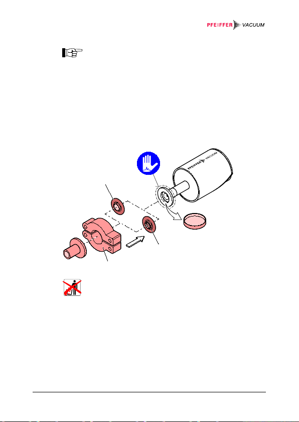
Clamp
Seal with centering ring
or
Seal with centering ring
and filter
Protective lid
Install the gauge vibration-free wherever possible. The
installation position is arbitrary. To prevent condensate and
particles accumulating in the measurement chamber, the
installation position should be horizontal or upright, and a seal
with centering ring and filter must be fitted where necessary.
If calibration of the gauge is possible in the installed condition,
you must ensure easy access to the buttons with a pin
(→ 18).
Remove the protective cap and connect the product to the
vacuum system.
BG 5136 BEN/C (2019-06) 15
Store the protective cap in a safe place.

DANGER
provided for the cable leading to the gauge.
3.2 Electrical connection
The gauge must be correctly connected to the vacuum
equipment (→ 13).
The gauge may only be connected to supply
devices or measurement instruments that comply
with the requirements of the earthed protective
extra low voltage (PELV). Protection must be
Earth loops, potential differences or EMC can influence
the measuring signal. Please observe the following
notes on installation to ensure optimum signal quality:
• Connect the cable shielding with the earth via the
connector housing on one side only. Leave the other
end of the shielding open.
• Connect the supply earth directly with protective earth
for power supply pack.
• Use the differential measuring input (separate signaland supply earth).
• Potential difference between supply earth and
housing ≤18 V (overvoltage protection)
16 BG 5136 BEN/C (2019-06)

If no measurement cable is present, a measurement cable
Electrical connection
Pin 1 Gauge identification
Pin 2 Signal output (measuring signal)
Pin 3 Signal common
Pin 4 Supply
Pin 5 Supply common
Pin 6 Chassis ground
Connector,
soldering side
2
5
3
1
6
4
–
+
–
+
2
3
1
4
5
100k
100nF
18 V
6
13K2
•
The cable must be shielded and grounded as
indicated in the above Illustration and the
Grounding concept *).
•
Connect the cable shield to ground on the
gauge side via Pin 6. Do not connect the other
side of the shield to prevent a ground circuit.
*)
→
"Technical Data"
can be fitted in accordance with the following diagram.
Connect the measurement cable to the gauge and secure
the cable connector using the locking screw.
Connect the measurement cable to the measurement
instrument.
BG 5136 BEN/C (2019-06) 17

Warm-up period
the specifications)
>¼ of an hour
calibration
>2 hours
ZERO
RUN
For factory
setting only
LED
Condition
Meaning
<RUN>
lights up
Measuring mode
range
4 Operation
Start up the gauge.
• for general pressure measurements (within
• for precision measurements and zero point
4.1 Indicate (to)
is flashing Other mode, error,
outside of measuring
4.2 Calibrating the gauge
The gauge is calibrated in the vertical upright position before
leaving the factory (→ "Calibration Test Report").
We recommend setting the zero point for initial
operation.
Long-term operation and contamination can lead to a zero point
shift, and may also necessitate a periodic zero adjustment.
18 BG 5136 BEN/C (2019-06)

Perform a zero adjustment for identical and constant ambient
F.S.
U / 90°
1000 hPa
≈2 mV
100 hPa
≈10 mV
10 hPa
≈50 mV
1 hPa
≈300 mV
0.1 hPa
≈1.8 V
for zero adjustment
0.11 hPa
<1×10⁻⁵ Torr
<1×10⁻⁵ hPa
<1×10⁻⁵ mbar
conditions and with the same installation position in which the
gauge is normally used.
The output signal is dependent upon the installation position.
Shifting from a vertical upright position to a horizontal position
constitutes:
∆
If the gauge is operated with a measurement instrument,
the zero adjustment must be performed at the
measurement instrument for the entire measuring
system: Calibrate the gauge first, and then the
measurement instrument.
4.2.1 <ZERO> Adjust
Evacuate the gauge up to the pressure stipulated in the
following table:
Recommended ultimate pressure
BG 5136 BEN/C (2019-06) 19
1,100 hPa
110 hPa
11 hPa
1.1 hPa
If the ultimate pressure is too high during zero adjustment
(>25% of F.S.), zero is no longer achievable and the LED
<RUN> starts flashing. In this case, first activate the factory
settings and then calibrate the zero point again (→ 22).
<4×10⁻² Torr
-3
<4
×10
Torr
-4
<4
×10
Torr
-5
<4
×10
Torr
<5×10⁻² hPa
-3
<5
×10
hPa
-4
<5
×10
hPa
-5
<5
×10
hPa
<5×10⁻² mbar
-3
<5
×10
mbar
-4
<5
×10
mbar
-5
<5
×10
mbar

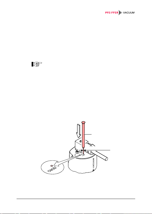
Operate the gauge for at least 2 hours (until the measured
Press the button
max. ø1.1 mm
value stabilizes).
Push the <ZERO> button briefly with a pin (max. ø1.1 mm). The
zero point is calibrated automatically. The LED <RUN>
continues to flash until calibration is complete (duration ≤8 s).
Following calibration of the zero point, the gauge returns
automatically to measuring mode. The LED <RUN>
lights up.
The LED <RUN> flashes
• if the transmitter is indicating a negative output signal
(> 22 mV) with ultimate pressure, or
• if calibration of the zero point has failed.
4.2.2 <ZERO> Adjust with ramp function
The ramp allows the zero point to be set with an established
reference pressure that is within the measuring range of the
gauge.
20 BG 5136 BEN/C (2019-06)
Furthermore, an offset of the characteristic can be set with the
max. ø1.1 mm
Keep the button
depressed
ramp in order to
• compensate an offset from the measurement system, or
• to generate a slightly positive zero point for a 0 … 10 V
AD-converter.
The offset should not be greater than 2% of the F.S. (+160 mV).
A greater positive offset will exceed the upper measuring range
limit.
Recommended procedure for offset adjustment for
measurement systems: → Note 19.
Operate the gauge for at least ¼ of an hour (until the
measured value stabilizes).
Push the <ZERO> button with a pin (max. ø1.1 mm), and
hold pressed. The LED <RUN> starts to flash. After 5 s, the
zero-adjust value is continuously (ramp) changed from the
current output value until the button is released or the
setting limit (max. 25% F.S.) is reached. The signal is
issued with a delay of approx. 1 s at the signal output.
BG 5136 BEN/C (2019-06) 21

Press the <ZERO> button again:
second)
<RUN> changes briefly)
Fine adjustment
within 0...3 s:
Zero-adjust value changes by one
unit (press button approx. 1 x every
Direction change
within 3...5 s:
If the <ZERO> button is not pressed again within a period of
5 s, the gauge returns to measuring mode.
The LED <RUN> starts to flash when the gauge indicates a
negative output signal.
Zero-adjust setting changes the
direction (flash frequency of the LED
4.3 Factory reset
All parameters set/changed by the user (e.g. zero point, filter)
are reset to the standard values (factory settings).
A reset of the standard values cannot be undone.
Load factory settings:
Shutting down the gauge.
Hold the <ZERO> button pressed ≥5 s during
commissioning of the gauge.
22 BG 5136 BEN/C (2019-06)

WARNING
drop to the floor.
DANGER
the safety measures are adhered to.
Caution
damage.
5 Dismantling
WARNING: Risk of breakage
Impacts can destroy the ceramic sensor.
Avoid harsh impacts and never allow the product to
DANGER: Contaminated parts
Contaminated parts can be harmful to health and to
the environment.
Inform yourself about any contamination before
starting work. Observe the applicable guidelines
when handling contaminated parts and make sure
Caution: Vacuum components
Dirt and damage impair the function of the vacuum
component.
When handling vacuum components, observe the
rules relating to cleanliness and protection against
BG 5136 BEN/C (2019-06) 23

Caution
Caution: Area sensitive to contamination
Wear clean, lint-free gloves and use clean tools.
Touching the product, or parts of the product with
bare hands will increase the rate of desorption.
Vent the vacuum system.
Shut down the gauge.
Loosen the locking screw and remove the measurement
cable.
Dismantle the gauge from the vacuum system and fit the
protective cap.
6 Maintenance, repair
The product is maintenance-free, provided that orderly operating
conditions are upheld.
Malfunctioning of the gauge as a direct result of
contamination is not covered by the warranty.
We recommend that you check the zero point
periodically (→ 19).
Pfeiffer Vacuum shall assume no responsibility nor provide any
warranty if the operating company or a third party performs the
repair work.
24 BG 5136 BEN/C (2019-06)

WARNING
Contamination *) to be included.
DANGER
the safety measures are adhered to.
7 Returning the product
WARNING: Shipping of contaminated products
Contaminated products (e.g. by radioactive, toxic,
corrosive or microbiological means) can be harmful
to health and to the environment.
Products should be free of contaminants during
delivery wherever possible. Observe the shipping
guidelines of the respective countries and transport
companies. Completed Declaration of
*)
Form available at www.pfeiffer-vacuum.de
Products not clearly declared "Free of contamination" will be
decontaminated at your cost.
If you do not include a completed Declaration of Contamination,
all delivered products will be immediately returned with costs.
8 Disposal of the product
DANGER: Contaminated parts
Contaminated parts can be harmful to health and to
the environment.
Inform yourself about any contamination before
starting work. Observe the applicable guidelines
when handling contaminated parts and make sure
BG 5136 BEN/C (2019-06) 25
WARNING
substances in accordance with local regulations.
WARNING: Environmentally hazardous substances
Products or parts thereof (mechanical and
electrical components, operating fluid, etc.) can
cause environmental damage.
Dispose of the environmentally hazardous
Breaking down the components
After the product has been dismantled, the components must be
separated into the following categories for disposal:
• Contaminated components
Contaminated components (radioactive, toxic, corrosive,
microbiological etc.) must be decontaminated in accordance
with the regulations of the respective country, separated by
material type and disposed of accordingly.
• Non-contaminated components
These components must be separated by material type and
recycled.
26 BG 5136 BEN/C (2019-06)

mm Hg
mbar
1
1×10⁻³
100 1 0.1
0.75
bar
Pa
0.01
1×10⁻⁵ 1 0.01
1×10⁻³
7.5×10⁻³
hPa
1
1×10⁻³
100 1 0.1
0.75
kPa
10
0.01
1×10³
10 1 7.5
Torr
mm Hg
1 Pa = 1 N/m2
Conversion table
mbar bar Pa hPa kPa Torr
1×10³ 1 1×10⁵ 1×10³ 100 750
1,332 1,332×10-3 133.32 1.3332 0.1332 1
ETL-Certification
3103457
ETL LISTED
The products CMR 361 … CMR 365
• conform to the UL Standard
UL 61010-1
• are certified to the CSA Standard
CSA C22.2 # 61010-1
BG 5136 BEN/C (2019-06) 27

Aßlar, Monday, April 18, 2016
Managing Director
EU-Declaration of Conformity
Pfeiffer Vacuum, hereby confirms that the following product
conforms to EMC Directive 2014/30/EU and RoHS Directive
2011/65/EU.
Ceramic Capacitance Gauge
CMR 361 … CMR 365
Standards
Harmonized standards and applied national standards and
specifications:
• EN 61000-6-2:2005
• EN 61000-6-3:2007 + A1:2011
• EN 61010-1:2010
control equipment)
• EN 61326-1:2013
control equipment)
Manufacturer/Signatures
Pfeiffer Vacuum GmbH, Berliner Straße 43, D-35614 Aßlar
(EMC immunity to interference)
(EMC immunity to interference)
(Safety regulations for electrical measuring and
(EMC requirements for electrical measuring and
Dr. Ulrich von Hülsen
28 BG 5136 BEN/C (2019-06)

Notes
BG 5136 BEN/C (2019-06) 29

Notes
30 BG 5136 BEN/C (2019-06)

Notes
BG 5136 BEN/C (2019-06) 31

A PASSION FOR PERFECTION
Vacuum solutions
from a single source
Complete
range of products
Competence in
theory and practices
Are you looking for a perfect
vacuum solution?
Then contact us at:
Translation: English BG 5136 BEN / C (2019-06)
Worldwide, Pfeiffer Vacuum stands f or innovative and
customized vacuum solutions, technologic al perfection,
competent consultation and reliable serv ice.
From an individual component through to com plex systems:
We are the only vacuum technology pro vider to offer a
complete range of products.
Take advantage of our know-how and our tr aining offer!
We will support you in system planning, and we offer first-classon-site service worldwide.
Pfeiffer Vacuum GmbH
Headquarters ● Germany
Tel.: +49 6441 802-0
info@pfeiffer-vacuum.de
www.pfeiffer-vacuum.de
 Loading...