

Page 1

296-12-19 008/002
Betriebsanleitung engl. 06.12
DOKU-SEAM-SYSTEM
3741
3745
Page 2

The reprinting, copying or translation of PFAFF Instruction Manuals, whether in whole or
in part, is only permitted with our previous authorization and with written reference to the
source.
PFAFF Industriesysteme
und Maschinen AG
Hans-Geiger-Str. 12 - IG Nord
D-67661 Kaiserslautern
Page 3

Index
Contents ................................................................................ Page
Register 01
................................................................................................. 5
1
Safety .................................................................................................................................... 7
1.01 Directives ...............................................................................................................................7
1.02 General notes on safety ......................................................................................................... 7
1.03 Safety symbols ......................................................................................................................8
1.04 Important points for the user ................................................................................................. 8
1.05 Operating and specialist personnel ........................................................................................ 9
1.05.01 Operating personnel .............................................................................................................. 9
1.05.02 Specialist personnel ............................................................................................................... 9
1.06 Danger warnings .................................................................................................................. 10
Register 02 ............................................................................................... 11
2
Input .................................................................................................................................... 14
2.01 General information ............................................................................................................. 14
2.02 Overview of the functions ................................................................................................... 15
2.03 Description of the functions ................................................................................................ 16
2.03.01 Overlapping functions .......................................................................................................... 16
2.03.02 Operating modes ................................................................................................................. 17
2.03.03 Tools ..................................................................................................................................... 17
2.04 Creating seam programs .....................................................................................................18
2.04.01 Sewing parameter input .......................................................................................................22
2.04.02 Input of action at beginning of seam sector ........................................................................ 23
2.04.03 Input of end of seam sector ............................................................................................... 24
2.04.04 Input of action at end of seam sector ................................................................................. 25
2.04.05 Thread force .........................................................................................................................27
2.05 Service ................................................................................................................................. 29
2.06 Cold start ............................................................................................................................. 30
2.07 Users – rights ....................................................................................................................... 31
2.08 Backup – restore .................................................................................................................. 33
2.09 Label-editor .......................................................................................................................... 35
2.10 Defi ning options and interfaces ........................................................................................... 37
Register 03 ...............................................................................................37
3
Betriebsanleitung ...............................................................................................................39
3.01 Proper use............................................................................................................................ 40
3.02 Specifi cations .......................................................................................................................41
3.03 Disposal of Machine ............................................................................................................42
3.04 Transportation, packing and storage .................................................................................... 43
3.04.01 Transportation to customer‘s premises ............................................................................... 43
Page 4

Index
Contents ................................................................................ Page
3.04.02 Transportation inside the customer‘s premises ................................................................... 43
3.04.03 Disposal of packing materials .............................................................................................. 43
3.04.04 Storage ................................................................................................................................ 43
3.05 Explanation of symbols ........................................................................................................ 44
3.06 Controls ...............................................................................................................................45
3.06.01 On/off switch / Sewing lamp switch .................................................................................... 45
3.06.02 Power bar ............................................................................................................................ 45
3.06.03 Keyboard on machine head .................................................................................................. 46
3.06.04 Pedal .................................................................................................................................... 48
3.06.05 Lever for lifting the presser foot ........................................................................................... 48
3.06.06 Knee switch (optional) .......................................................................................................... 49
3.06.07 Bobbin thread supply monitor ............................................................................................. 49
3.06.08 Adjustment of the stand height (optional) ........................................................................... 50
3.06.09 Touch-screen monitor .......................................................................................................... 50
3.06.10 Label-printer ......................................................................................................................... 51
3.06.11 Hand-held scanner ............................................................................................................... 51
3.06.12 PC ........................................................................................................................................51
3.07 Setting up ............................................................................................................................. 52
3.07.01 Log-in ................................................................................................................................... 52
3.07.02 Language selection .............................................................................................................. 52
3.07.03 Inserting the needle ............................................................................................................ 53
3.07.04 Winding the bobbin thread, regulating the winder tension (PFAFF 3741+ 3745 PLUS) ....... 54
3.07.05 Winding the bobbin thread, regulating the winder tension (PFAFF 3745 PREMIUM) .......... 55
3.07.06 Bobbin-changing/threading, and regulating the bobbin thread tension ................................ 56
3.07.07 Threading the needle thread (PFAFF 3741 PLUS + 3745 PLUS) ............................................57
3.07.08 Threading the needle thread (PFAFF 3745 PREMIUM) ..........................................................58
3.08 Sewing .................................................................................................................................59
3.08.01 Calling up / carry out the sewing operation (without camera for bobbin thread monitor) .... 59
3.08.02 Calling up / carry out the sewing operation (with camera for bobbin thread monitor) ......... 60
3.08.03 Regulating the needle thread tension (PFAFF 3741 + 3745 PLUS) ........................................ 62
3.08.04 Regulating the needle thread tension (PFAFF 3745 PREMIUM) ........................................... 64
3.08.05 Description of the functions ................................................................................................ 66
3.08.06 Concluding the sewing operation ........................................................................................ 68
3.09 Care and maintenance ......................................................................................................... 69
3.09.01 Servicing and maintenance intervals ................................................................................... 69
3.09.02 Cleaning the machine .......................................................................................................... 69
3.09.03 Lubricating ........................................................................................................................... 70
3.09.04 Checking/regulating the air pressure ................................................................................... 71
3.09.05 Emptying/cleaning the water bowl of the air fi lter/regulator ................................................ 71
3.10 Wearing parts ....................................................................................................................... 72
Page 5

Index
Contents ................................................................................ Page
Register 04
............................................................................................... 73
4
Adjustment ......................................................................................................................... 76
4.01 Notes on adjustment ........................................................................................................... 76
4.02 Tools, gauges and other accessories for adjusting ............................................................. 76
4.03 Abbreviations ....................................................................................................................... 76
4.04 Explanation of the symbols .................................................................................................. 76
4.05 Adjusting the basic machine ................................................................................................77
4.05.01 Basic position of the balance wheel (adjustment aid) .......................................................... 77
4.05.02 Zero position of the bottom and needle feed ...................................................................... 78
4.05.03 Feed dog motion of bottom feed dog and needle feed .......................................................79
4.05.04 Feeding motion of the bottom feed dog .............................................................................. 80
4.05.05 Height of the bottom feed dog ............................................................................................81
4.05.06 Feeding stroke difference ....................................................................................................82
4.05.07 Preliminary adjustment of the needle height ....................................................................... 83
4.05.08 Needle rise, hook clearance, needle height and bobbin case position fi nger ...................... 84
4.05.09 Bobbin case opener ............................................................................................................. 85
4.05.10 Bobbin winder ...................................................................................................................... 86
4.05.11 Thread check spring and thread regulator ............................................................................ 87
4.05.12 Sewing foot pressure ........................................................................................................... 88
4.05.13 Lubrication ...........................................................................................................................89
4.05.14 Reengaging the slip clutch ................................................................................................... 90
4.06 Adjusting the thread trimmer -900/81 .................................................................................. 91
4.06.01 Resting position of the roller lever / radial position of the control cam ................................ 91
4.06.02 Position and height of the thread catcher ............................................................................ 92
4.06.03 Knife pressure ......................................................................................................................93
4.06.04 Bobbin thread clamp spring ................................................................................................. 94
4.06.05 Manual cutting test .............................................................................................................. 95
4.07 Setup .................................................................................................................................... 96
4.07.01 Set reference position .......................................................................................................... 96
4.07.02 Stitch length adjustment ...................................................................................................... 97
4.07.03 Commissioning the scanner ................................................................................................ 98
4.07.04 Commissioning the camera ................................................................................................. 99
4.07.05 Adjustment of edge guide photocell ................................................................................. 102
4.08 Parameter settings ............................................................................................................. 103
4.08.01 Selecting and altering the parameters ............................................................................... 103
4.08.02 Parameter list ..................................................................................................................... 104
4.09 Description of the error messages .....................................................................................112
4.10 Inputs / Outputs ..................................................................................................................113
4.11 Pin assignment ...................................................................................................................114
4.12 Importend Sevice-information ............................................................................................117
Page 6

Index
Contents ................................................................................ Page
Register 05
............................................................................................. 117
5
Calibration ........................................................................................................................ 120
5.01 General information ........................................................................................................... 120
5.01.01 Calibration .......................................................................................................................... 120
5.01.02 Traceability ......................................................................................................................... 120
5.01.03 Standards ........................................................................................................................... 120
5.01.04 Gauging offi ce, German Calibration Offi ce DKD ................................................................ 121
5.02 Calibration procedure ......................................................................................................... 121
5.02.01 Check / adjust the needle reference position ..................................................................... 121
5.02.02 Check / adjust the trigger signals ....................................................................................... 122
5.02.03 Check the zero position of the monitor power signal ........................................................ 123
5.02.04 Checking the setting of the sewing head........................................................................... 124
5.02.05 Recording the characteristic thread strength curve ........................................................... 124
5.03 Checking the calibration (calibration result) ........................................................................ 127
Register 06 ............................................................................................. 127
6
Circuit diagrams ...............................................................................................................129
6.01 Pneumatics-switch diagram PFAFF 3741 + 3745 .............................................................. 129
6.02 Block diagram PFAFF 3741 + 3745 (with control unit P374 ED) ......................................... 130
6.03 Circuit diagrams ................................................................................................................. 132
Page 7

Register 01
Page 8

Page 9

7
Safety
1 Safety
1
.01 Directives
This machine is constructed in accordance with the European regulations contained in the
conformity and manufacturer’s declarations.
In addition to this Instruction Manual, also observe all generally accepted, statutory and
other regulations and legal requirements and all valid environmental protection regulations!
The regionally valid regulations of the social insurance society for occupational accidents or
other supervisory organizations are to be strictly adhered to!
1.02 General notes on safety
● This machine may only be operated by adequately trained operators and only after having
completely read and understood the Instruction Manual!
● All Notes on Safety and Instruction Manuals of the motor manufacturer are to be read be-
fore operating the machine!
● The danger and safety instructions on the machine itself are to be followed!
● This machine may only be used for the purpose for which it is intended and may not be
operated without its safety devices. All safety regulations relevant to its operation are to
be adhered to.
● When exchanging sewing tools (e.g. needle, roller presser, needle plate and bobbin),
when threading the machine, when leaving the machine unattended and during maintenance work, the machine is to be separated from the power supply by switching off the
On/Off switch or by removing the plug from the mains!
● Everyday maintenance work is only to be carried out by appropriately trained personnel!
● Repairs and special maintenance work may only be carried out by qualifi ed service staff
or appropriately trained personnel!
● Work on electrical equipment may only be carried out by appropriately trained personnel!
● Work is not permitted on parts and equipment which are connected to the power supply!
The only exceptions to this rule are found in the regulations EN 50110.
● Modifi cations and alterations to the machine may only be carried out under observance
of all the relevant safety regulations!
● Only spare parts which have been approved by us are to be used for repairs! We express-
ly point out that any replacement parts or accessories which are not supplied by us have
not been tested and approved by us. The installation and/or use of any such products can
lead to negative changes in the structural characteristics of the machine. We are not liable
for any damage which may be caused by non-original parts.
Page 10
8
Safety
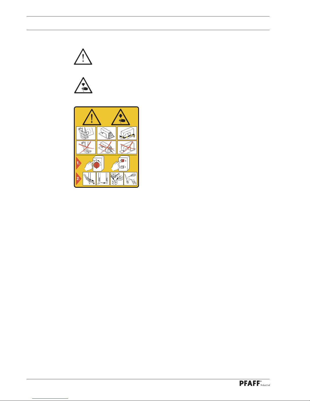
1.03 Safety symbols
Danger!
Points to be observed..
Danger of injury for operating and specialist personnel!
Caution
Do not operate without fi nger guard and safety devices.
Before threading, changing bobbin and needle, cleaning
etc. switch off main switch.
I
1.04 Important points for the user
● This Instruction Manual is an integral part of the machine and must be available to the
operating personnel at all times.
● The Instruction Manual must be read before operating the machine for the fi rst time.
● The operating and specialist personnel is to be instructed as to the safety equipment of
the machine and regarding safe work methods.
● It is the duty of the user to only operate the machine in perfect running order.
● It is the obligation of the user to ensure that none of the safety mechanisms are removed
or deactivated.
● It is the obligation of the user to ensure that only authorized persons operate and work
on the machine.
Further information can be obtained from your PFAFF agent.
Page 11

9
Safety
1.05 Operating and specialist personnel
1
.05.01 Operating personnel
Operating personnel are persons responsible for the equipping, operating and cleaning of
the machine as well as for taking care of problems arising in the sewing area.
The operating personnel is required to observe the following points and must:
● always observe the Notes on Safety in the Instruction Manual!
● never use any working methods which could adversely affect the safety of the machine!
● not wear loose-fi tting clothing or jewelery such as chains or rings!
● also ensure that only authorized persons have access to the potentially dangerous area
around the machine!
● always immediately report to the person responsible any changes in the machine which
may limit its safety!
1.05.02 Specialist personnel
Specialist personnel are persons with a specialist education in the fi elds of electrics, electronics and mechanics. They are responsible for the lubrication, maintenance, repair and adjustment of the machine.
The specialist personnel is obliged to observe the following points and must:
● always observe the Notes on Safety in the Instruction Manual!
● switch off the On/Off switch before carrying out adjustments or repairs, and ensure that
it cannot be switched on again unintentionally!
● wait until the luminous diode on the control box is no longer blinking or on before begin-
ning adjustment or repair work.
● never work on parts which are still connected to the power supply! Exceptions are explai-
ned in the regulations EN 50110.
● replace the protective coverings and close the electrical control box afer all repairs or
maintenance work!
Page 12
10
Safety
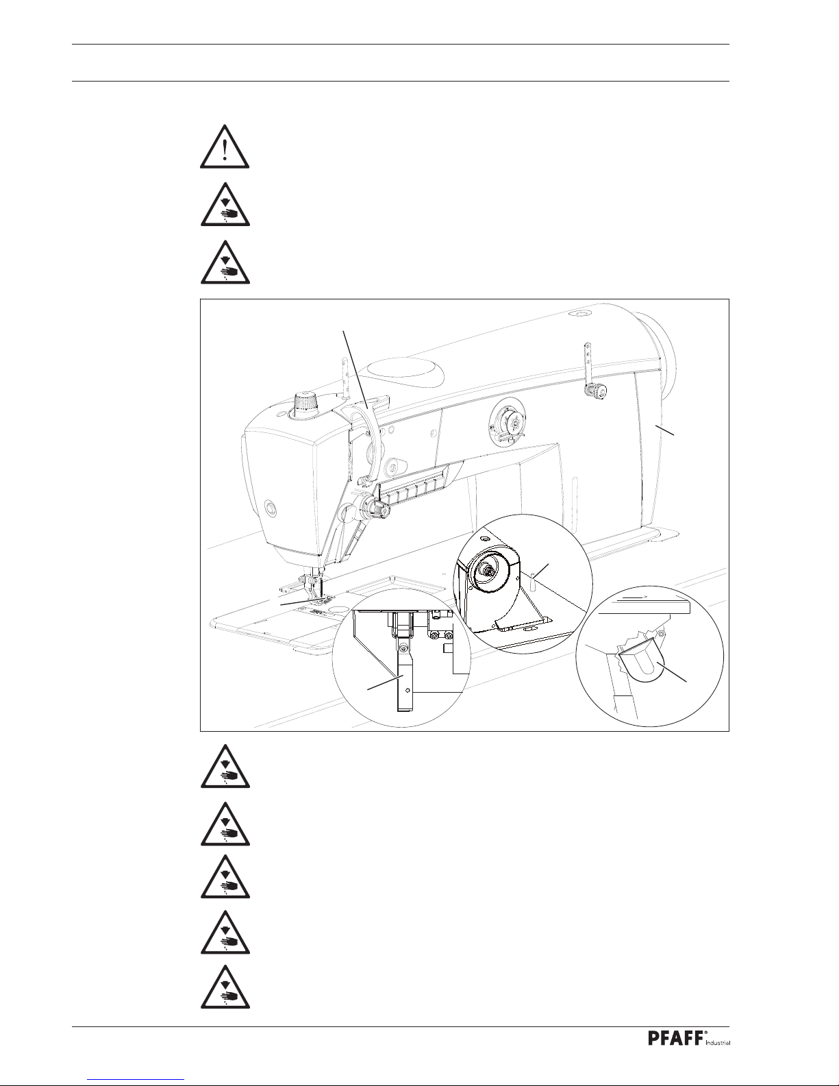
1.06 Danger warnings
A working area of 1 m must be kept free both in front of and behind the machine, so that easy access is possible at all times.
Never put your hands or fi ngers in the sewing area during sewing!
Danger of injury by the needle!
While setting or adjusting the machine do not leave any objects on the table nor
in the needle plate area! Objects may be trapped or fl ung out of the machine!
Do not run the machine without fi nger guard 1!
Danger of injury by up and down movement of needle!
Do not run the machine without take-up lever guard 2!
Danger of injury by moving take-up lever!
Do not run the machine without belt guards 3 and 4!
Danger of injury by rotating v-belt!
Do not operate the machine without tilt lock 5!
Danger of crushing between sewing head and table!
Do not operate the machine without support 6! Danger due to top-heavy
sewing head! Machine can tip over backwards when tilted!
Fig. 1 - 01
2
1
3
4
6
5
Page 13

PFAFF Industriesysteme und Maschinen AG, 67661 Kaiserslautern
Declaration of acknowledgement
of the documentation for the PFAFF-DOKU-SEAM-SYSTEM
Customer:................................................................................................................................................
Address:...................................................................................................................................................
Machine: PFAFF 3741 ................................... Serial-Nr.: ................................................................
Machine: PFAFF 3745 ................................... Serial-Nr.: ................................................................
PC-software: ................................................. Control software:.....................................................
Each person working on the PFAFF-DOKU-SEAM-SYSTEM must be familiar with and understand the
contents of these technical documents. The operating and qualifi ed personnel must be appropriately
authorised to handle the machine, i.e. qualifi ed and instructed. The operator promises to train his
personnel accordingly. Furthermore the user have to take care, to calibrate the machine, when the
control-box or the thread-force-sensor was changed.
We hereby confi rm that we have read and understood the documentation for the PFAFF-DOKU-SEAM-
SYSTEM
, and that in addition to the advice in the documentation, we will also follow the local safety and
accident prevention regulations.
Place:...................................................................................... Date:................................................
Operator:...................................................................................................................................................
Page 14

Page 15

Register 02
Page 16

Page 17

This instruction manual applies to
machines from software version 1.8
and serial number 2 763 625 onwards
Kurzanleitung zur Eingabe engl. 06.12
SHORT INSTRUCTIONS
FOR THE INPUT
3741
3745
Page 18

Input
14
2 Input
2
.01 General information
The effective pull of the needle thread (needle thread tension) is determined during sewing
for each stitch by means of a sensor installed in the needle thread path of the sewing machine.
In the process, through a special measuring principle, measuring errors, caused for example
by fl uctuating temperatures, can be ruled out.
The signals are evaluated on the PC and displayed on the touch-screen monitor on a user interface for Windows ® XP. The analysis of these signals gives information about the machine
setting and the quality of each individual stitch sewn.
The seam sector for which the system is to be activated (docu-seam sector) is determined
either by a sensor, by knee switch, with a pre-selected seam length or by stitch counting.
The docu-seam system compares the established thread pull with the previously entered
limit values and issues an evaluation of the seam on the touch-screen monitor. If the seam
is a good seam, an appropriate signal is given to the PC interface and a label can be printed,
which can then be attached to indicate the appropriate quality of the seam. The label can be
designed individually with an editor.
The docu-seam system also activates a missed stitch recognition function and, depending
on how it is set, reacts to following types of error:
- missed stitch,
- needle thread breakage, end of needle thread
- bobbin thread breakage, end of bobbin thread
- broken needle
- deviations from edge guide
The use of specifi ed materials can be ensured and documented through the prompt to enter
appropriate codes (e.g. scanning of barcodes for thread spindle, material, bobbin).
All inputs, for separate user groups, can be carried out directly over the user interface of the
touch screen monitor. Several languages are available for the user interface. All data entered
and established can be processed on standard databases and spreadsheets.
Page 19
Input
15
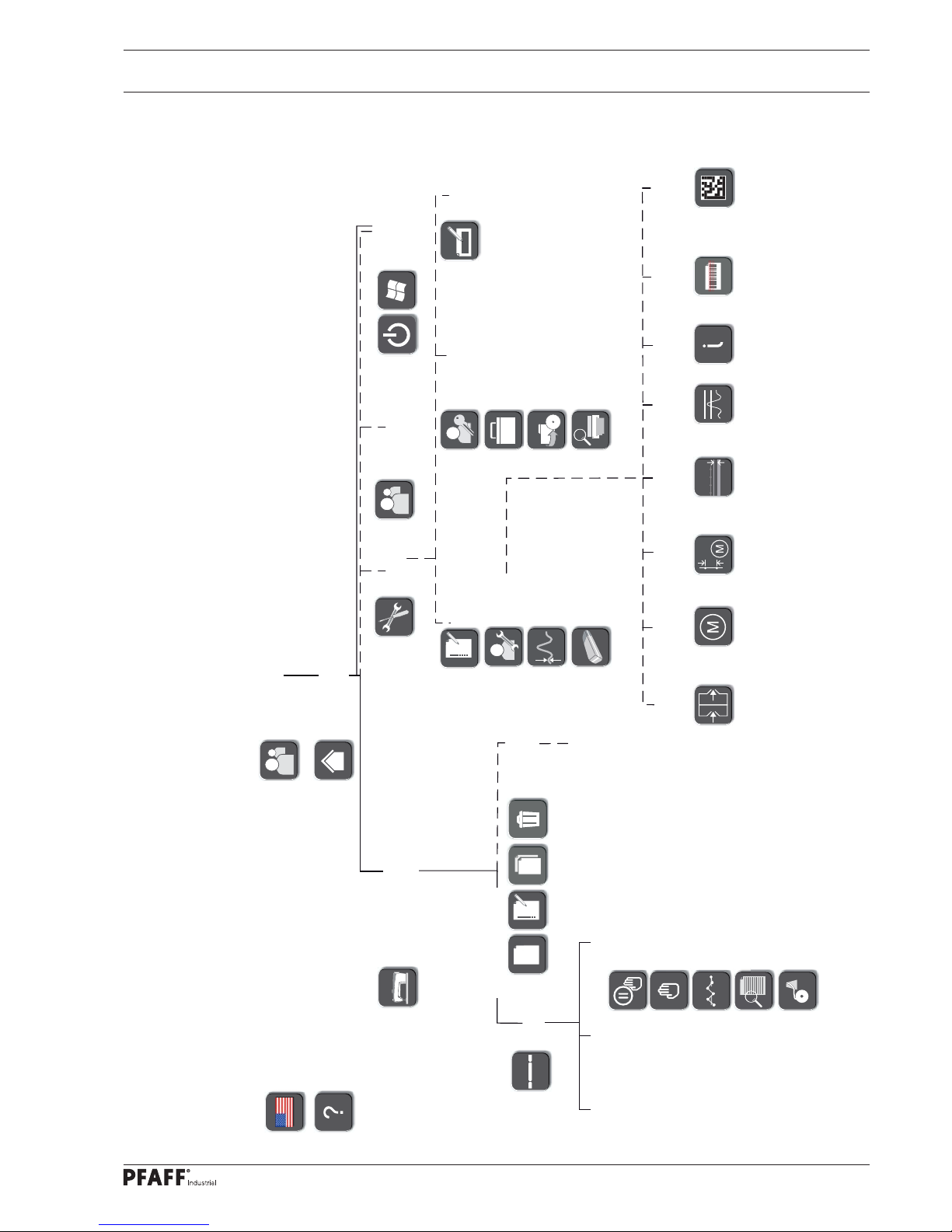
2.02 Overview of the functions
Pop-ups:
- Instruction box
- Error
- Warning - Keyboard
- Language selection
- Help mode
- Log-in
- Selection of oper-
ating mode
- Tools
- Change of
user
- Switch off
switch to
desktop /
computer
- Seam program selection +
configuration
- Production
Pop-ups:
- Error
- Warning
Info
display
Switch to:
- Manual interruption
- Manual sewing
- Test seam
- Work instructions
- Winding
Popups:
- Settings
- Seam program
creation
Work instructions
- Label- editor
- Users and rights
- Equipment + interfaces
- Backup and restore
- Evaluation and printing
- Parameterization
- Service
- Calibration
- Cold start
Inputs/outputs
Feed
regulator
configuration
Thread
force
Drives
Sensors
Version
Scanner
commissioning
Camera
commissioning
Page 20

Input
16
2.03 Description of the functions
Each function is selected by tapping the appropriate symbols on the touchscreen monitor.
2.03.01 Overlapping functions
Mode selection
The menu for selecting the operating mode is called up, see Chapter 2.03.02 Operating
modes.
Choice of language
A menu for selecting the language setting is opened, see Chapter 8 Setting up in the Instruction Manual.
Help mode
After calling up the help mode, the next function selected is described.
Online help
After activation of the help module, the online help can be called up, including language and
document selection.
Confi rm
The selection is confi rmed, entered or altered values are saved.
Stop
The selection process is cancelled, entered or altered values are not saved.
Back
The superordinate level is selected.
Drag and Drop
With this function it is possible to move the window to any position.
Work order
With this function, a previously created work order can be displayed.
Page 21
Input
17
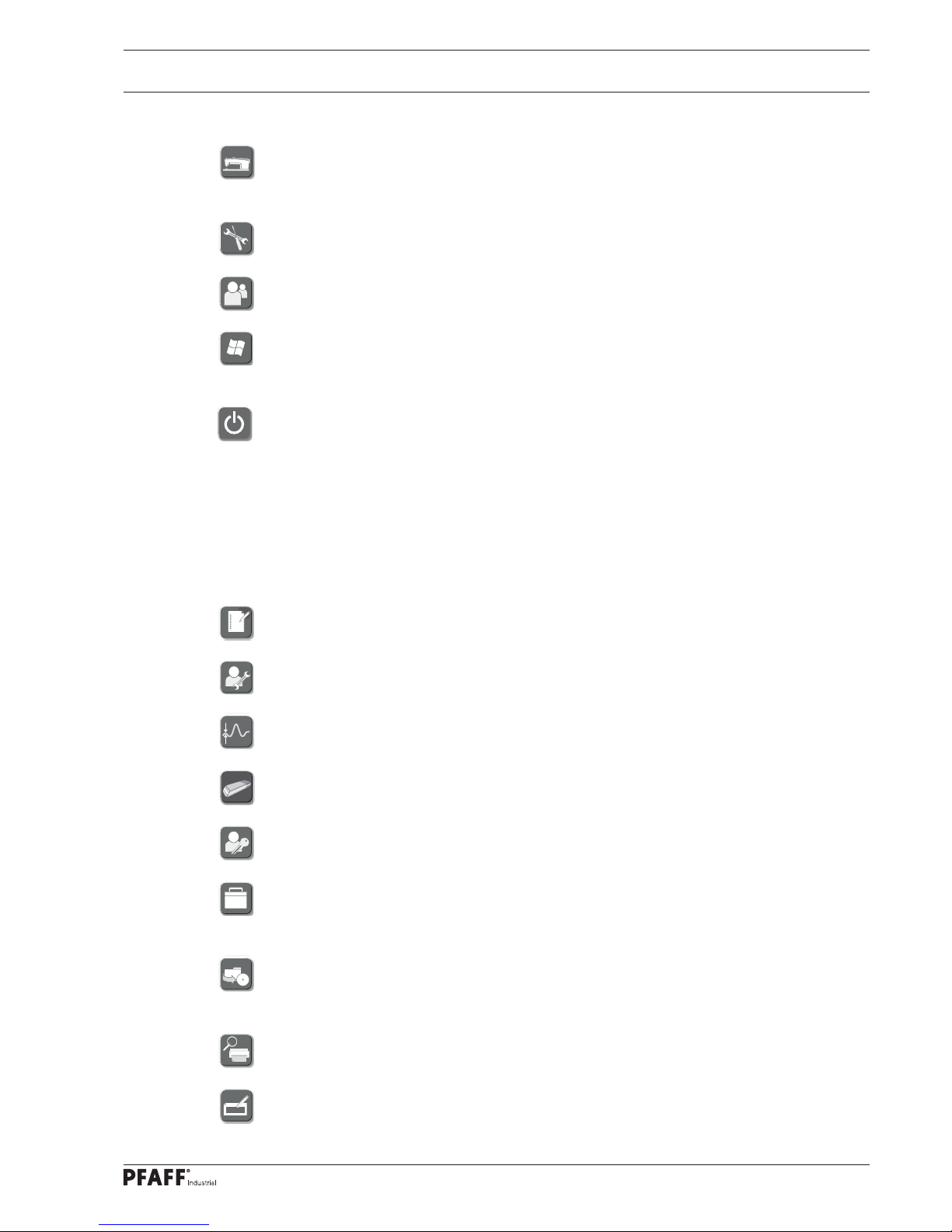
2.03.03 Tools
Parameterization
A menu is called up for adjusting the parameters, see Adjustment Manual.
Service
The service menu is called up, see Chapter 2.05 Service.
Calibration
A menu is called up for calibrating the machine, see Calibration Instructions.
Cold start
A cold start is carried out, see Chapter 2.06 Cold Start.
Users – Rights
A menu is called up for entering users and rights, see Chapter 2.07 Users – Rights.
Equipment and Interfaces
A menu is opened for allocating work aids to corresponding COM-interfaces, see
Chapter 2.10 Defi ning options and interfaces.
Backup and Restore
A menu is called up for carrying out a backup or a restoration, see Chapter 2.08 Back-up –
Restore.
Evaluation and print function
A selected docu-seam with all relevant values is displayed.
Label editor
A menu is called up for editing labels, see Chapter 2.09 Label editor.
2.03.02 Operating modes
Selecting and confi guring seam programs
Functions for selecting, processing and creating seam programs are called up, see Chapter
2.04 Creating seam programs.
Tools
A menu is called up for selecting functions for the sewing head, control unit and printer.
Change of user
The box for entering the user is called up.
Desktop
The application is concluded and the Windows desktop is called up. This function is only displayed for the logged-in administrator or supervisor.
Shut down the computer
The application is concluded and the computer is shut down. This function is only displayed
for the logged-in operator or guest.
Page 22
Input
18
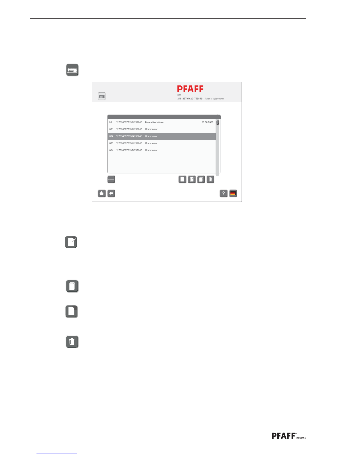
2.04 Creating seam programs
● Log-in as supervisor.
● Call up the seam program selection function.
There are several possibilities of how to create a seam program.
● Select a seam program from the list.
● Edit an existing seam program.
or
● Select a seam program from the list.
● Copy a seam program to create a new seam program on the basis of an existing one.
or
● Create a new seam program.
or
● Deleting a seam programme.
20.06.2006
20.06.2006
23.07.2006
24.07.2006
Industrial
Page 23
Input
19
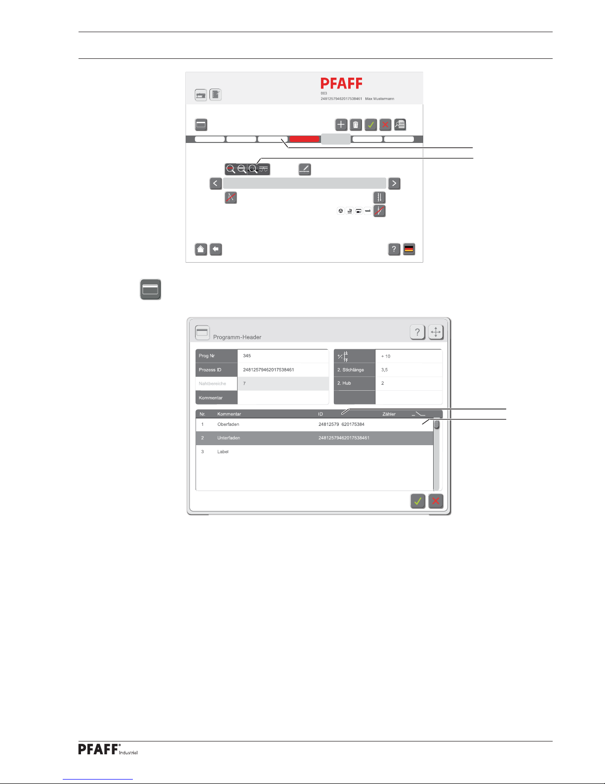
● Call up the Program Header function.
Industrial
1
2
● If necessary, enter/change the program number, process-ID and comment.
● Enter the value for the stitch length correction dependent on the material.
● Enter/change the value for the second stitch length (can be called up with the appropriate
key on the machine head).
● Enter/change the value for the second stroke (can be called up with the appropriate key
on the machine head).
● Enter top thread and bobbin thread ID in input fi eld 3, or scan in via hand scanner to
activate this function later in input fi eld 4.
Control will then only accept sewing material with that ID.
4
Material
@ @ @
1
1
X
X
0
1
5
6
0
0
Artikel 2b
3
4
Page 24
Input
20
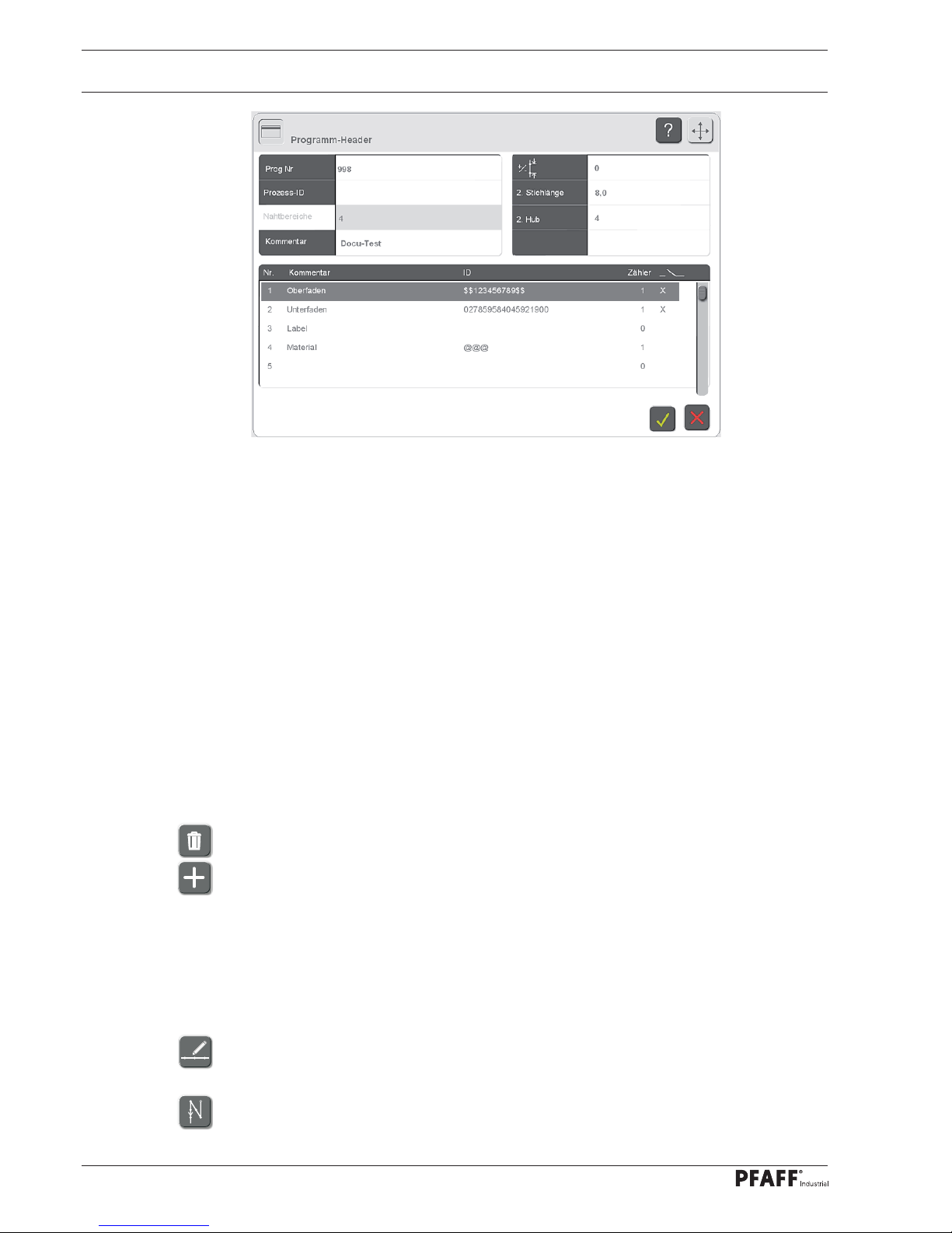
Input Scan Options with wildcard characters in the program-header
1. With input of $$ before a character string or $$ after a character string, only the character
string is controlled, true or not true.
All characters before or after the character string are only documented
Sample:
Header input: $$123456789$$
Bar code : 888881234567895555 OK documented in the protocol
Bar code : 77777712345678933333 OK documented in the protocol
Bar code 888881234567805555 nicht OK, Error not documented in the protocol.
2. Enter @ @ @ in input fi eld 3.
The control will not carry out any adjustments, IDs will only be logged.
● Select the data for printing the end label (value "1" = print label each time;
value "10" = print label every tenth time).
● Select seam section from sector 1.
● If necessary, delete selected seam section.
● If necessary, insert seam section after the selected seam section.
● With function 2 specify the following for the selected seam sector.
- Activate/deactivate docu-seam sector
- Activate/deactivate missed stitch recognition function
- Activate/deactivate edge guide recognition function
- Specify thread strength, see Chapter 2.04.05 Sensors
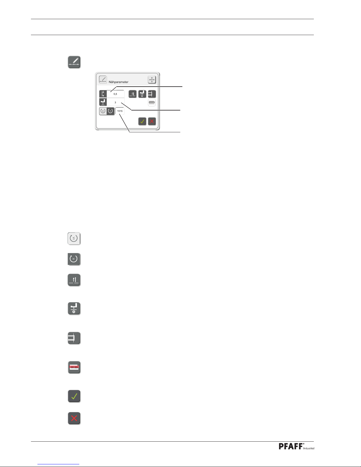
● Call up the menu for entering the sewing parameters and enter the appropriate values,
see Chapter 2.04.01 Sewing parameter input.
● Call up the menu for entering the action at beginning of the seam sector. Depending on
the action selected, the symbol may be different. In this example the "double start bartacks" action is selected.
Page 25

Input
21
● Select the action and enter/change the appropriate values, see Chapter 2.04.02 Input of
action at beginning of seam sector.
● Call up the menu for the input of the recognition of the end of the seam sector. Depend-
ing on the function selected, the symbol may be different. In this example the "recognition of the end of the seam section by knee switch" is selected.
● Select the function for the recognition of the end of the seam sector and, if necessary,
enter/change the appropriate values, see Chapter 2.04.03 Input of end of seam sector.
● Call up the menu for entering the action at the end of the seam sector. Depending on the
action selected, the symbol may be different. In this example the "condensed end stitches" action is selected.
● Select the action and, if necessary, enter the label number, see Chapter 2.04.04 Input of
action at end of seam sector.
● If necessary, shift the seam sector within the seam.
● After entering/editing the desired seam sectors, save the seam program and quit the
seam program function.
● Call up the production function.
Page 26
Input
22
Description of the functions
Stitch length input
After tapping area 1, the input menu for the stitch length in the current seam sector is called
up.
Sewing foot lift input
After tapping area 2, the input menu for the presser foot lift in the current seam sector is
called up.
Speed input
After tapping area 3 the input menu for the speed in the current seam sector is called up.
This function is used to select the variable speed. The speed can be adjusted with the pedal
position up to the maximum value (This function is activated in the example).
This function is used to select the constant speed. The speed cannot be adjusted with the
pedal position.
Needle raised at stop
This function is switched on or off for the current seam sector. If the function is switched on,
the needle moves to the top position when sewing stops.
Foot raised at stop
This function is switched on or off for the current seam sector. If the function is switched on,
the foot is raised when sewing stops.
Sew in label (only after a docu-seam area)
This function is switched on or off for the current seam sector. If the function is switched on,
a label is sewn in after the seam sector has been completed.
Scan label
This function is switched on or off for the current seam sector. If the function is switched on,
the label must be scanned.
Conclude the input
The input is concluded by taking over the selection and the entered values.
Stop the input
The input is concluded without taking over the selection and the entered values.
1
2
3
2
.04.01 Sewing parameter input
● In seam programming call up the menu for sewing parameter input.
Page 27
Input
23
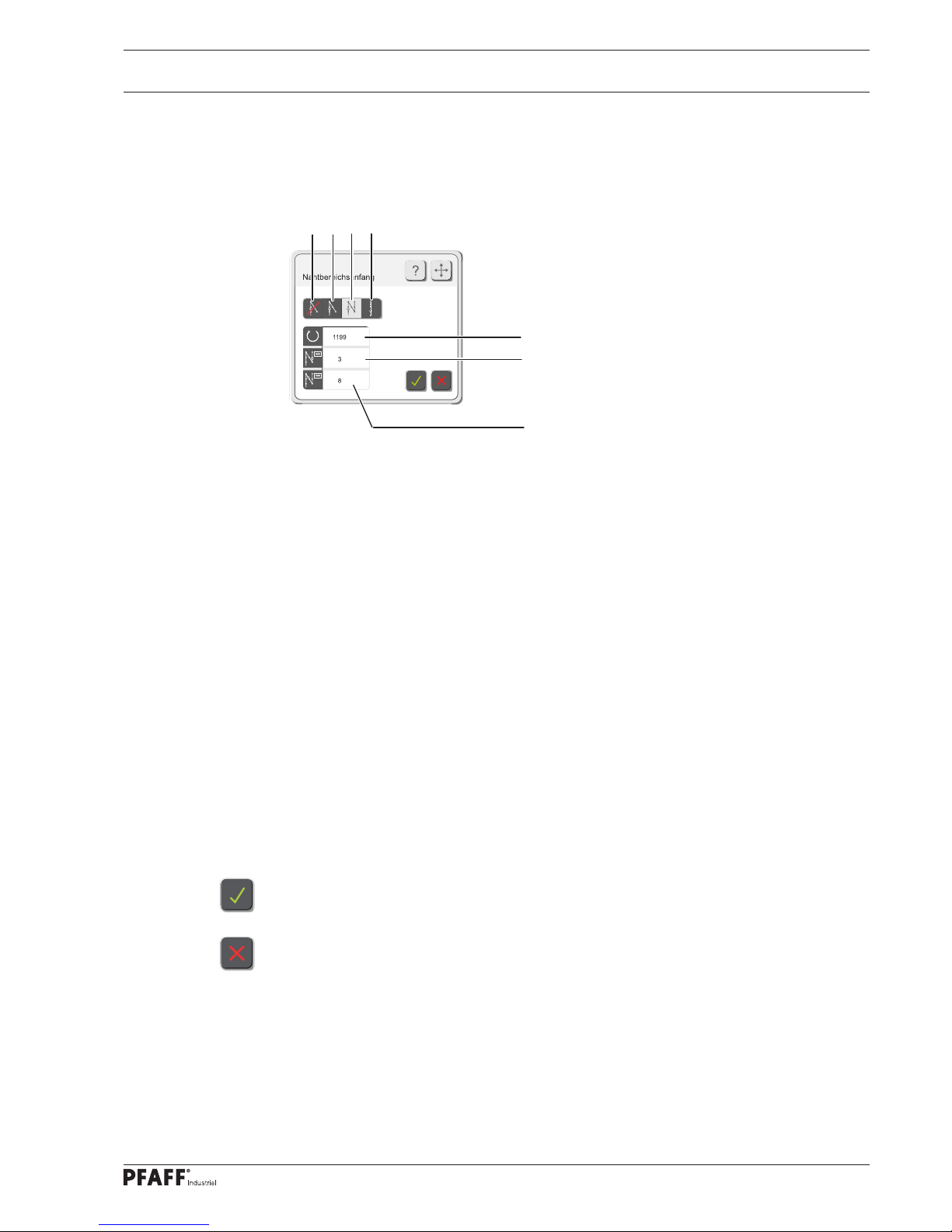
Description of the functions
Start bartacks and condensed start stitches off
After selecting function 1, neither a start bartack nor a condensed start stitch is sewn at the
beginning of the seam sector.
Start bartack
After the selection of this function and the input of the values for the tack speed in sector 5,
as well as the number of bartacks, the start bartack at the beginning of the seam sector is
sewn with the corresponding values.
Double start bartack (currently active)
After the selection of this function and the input of the values for the tack speed in sector 5,
the number of forward stitches in sector 6 and the number of reverse stitches in sector 7,
the double start bartack at the beginning of the seam sector is sewn with the corresponding
values.
Condensed start stitches
After the selection of this function and the input of the values for the stitch length and the
number of stitches, the condensed stitches at the beginning of the seam sector are sewn
with the corresponding values.
Conclude the input
The input is concluded by taking over the selection and the entered values.
Stop the input
The input is concluded without taking over the selection and the entered values.
2.04.02 Input of action at beginning of seam sector
● Call up the menu for the input of the action at the beginning of the seam, see Chapter
2.04 Creating seam programs.
1
5
2
3
4
6
7
Page 28
Input
24
2.04.03 Input of end of seam sector
● Call up the input for the recognition of the end of the seam sector, see Chapter 2.04 Cre-
ating seam programs.
1
2
345
6
7
8
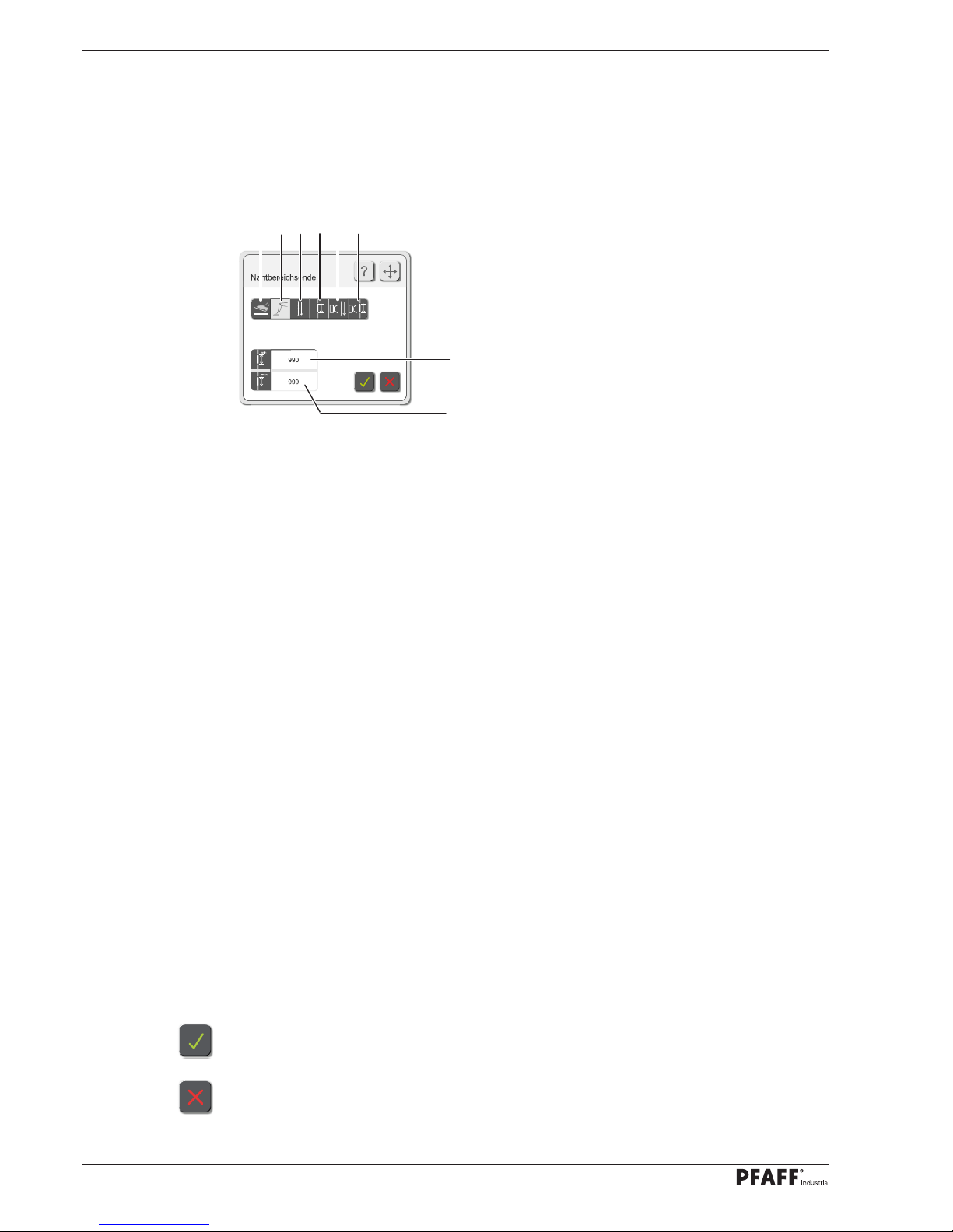
Description of the functions
End of seam sector by pedal function
After function 1 has been selected, the end of the seam sector is started with the pedal
function.
End of seam sector by knee switch
After function 2 has been selected, the end of the seam sector is started with the pedal
function. The minimum number of stitches for the seam sector is defi ned with sector 7, the
maximum number with sector 8.
End of seam sector by stitch counting
After function 3 has been selected and following the input of the value for the number of
stitches, the end of the seam sector is started after the corresponding number of stitches
have been sewn.
End of seam sector by seam length
After function 4 has been selected and following the input of the value for the seam length,
the end of the seam sector is started after the corresponding seam length has been sewn.
End of seam sector by sensor with stitch counting
After function 5 has been selected and following the input of the values for the maximum
and minimum number of stitches, the end of the seam sector is started by sensor according
to the number of stitches entered.
End of seam sector by sensor with seam length
After function 6 has been selected and following the input of the values for the maximum
and minimum seam length, the end of the seam sector is started by sensor within the corresponding lengths given.
Conclude the input
The input is concluded by taking over the selection and the entered values.
Stop the input
The input is concluded without taking over the selection and the entered values.
Page 29
Input
25
2.04.04 Input of action at end of seam sector
● Call up the menu for the input of the actions at the end of the seam, see Chapter 2.04
Creating seam programs.
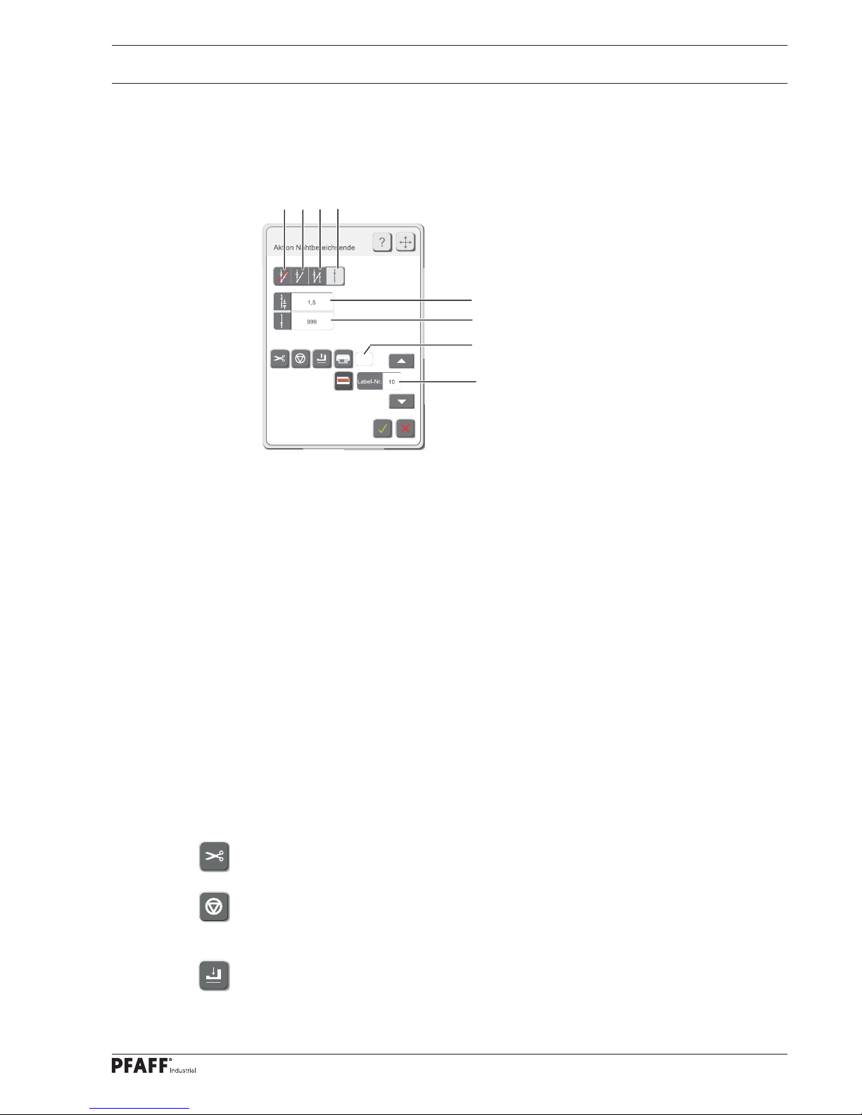
Description of the functions
End bartacks and condensed end stitches off
After selecting function 1, neither an end bartack nor a condensed end stitch is sewn at the
end of the seam sector.
End bartack
After the selection of this function 2 and the input of the values for the tack speed, as well
as the number of bartacks, the end bartack at the end of the seam sector is sewn with the
corresponding values.
Double end bartack
After the selection of this function 3 and the input of the values for the tack speed, the
number of forward stitches and the number of reverse stitches, the double end bartack is
sewn at the end of the seam sector with the corresponding values.
Condensed end stitches (currently active)
After the selection of this function 4 and the input of the values for the stitch length in sector 5 and the number of stitches in sector 6, the condensed stitches at the end of the seam
sector are sewn with the corresponding values.
Thread trimming on/off
This function is used to switch thread trimming at the end of the seam sector on or off.
Sewing stop
This function is switched on or off. If the function is switched on, the machine stops at the
end of the seam sector.
Foot lowered
This function is switched on or off. If the function is switched on, the foot remains down at
the end of the seam sector.
1
1
5
2
3
4
6
8
7
Page 30

Input
26
Print label on/off
This function is used to switch the label printing function at the end of the seam sector on or
off.
Selection of the label
The label, which is to be attached, can be selected in sector 7.
Label payout
The number of labels to be printed can be selected in range 8.
Scan label
This function is switched on or off for the current seam sector. If the function is switched on,
the label must be scanned.
Conclude the input
The input is concluded by taking over the selection and the entered values.
Stop the input
The input is concluded without taking over the selection and the entered values.
Page 31

Input
27
2.04.05 Thread force
● Call up the menu for entering the parameters for the sensor in the seam programming
menu or from the service menu.
Description of the functions
Hard top limit value
The limit value is entered in sector 1. In the docu-seam area this value must never be exceeded.
Hard bottom limit
The limit value is entered in sector 2. In the docu-seam area the value must never be lower
than this limit.
Bottom limit for missed stitch recognition
The limit value is entered in sector 3. If the value falls below this limit, a missed stitch is
recognised.
450
400
150
20
200
3
Fadenkraft
1
2
3
4
6
7
PFAFF 3741 PLUS
PFAFF 3745 PLUS
450
400
150
20
200
300
3
Fadenkraft
1
2
3
4
5
6
7
8
9
10
PFAFF 3745 PREMIUM
Page 32

Input
28
Soft top limit
The limit value is entered in sector 4 In the docu-seam area this value may be exceeded a
few times. The number of tolerance stitches is entered in sector 7.
Setpoint
(only on the PFAFF 3745 PREMIUM)
The Setpoint is entered in sector 5.
Soft bottom limit
The limit value is entered in sector 6. In the docu-seam area it is possible to drop below this
level a few times. The number of tolerance stitches is entered in sector 7.
Tolerance stitches
The number of tolerance stitches is entered in sector 7. The number of tolerance stitches is
used to defi ne how often the thread strength within the docu-seam area may exceed or drop
below the soft limits.
Thread tension control (only on the PFAFF 3745 PREMIUM)
Pressing the button 8 deactivates the function "Thread tension control" during sewing,
button 9 reactivates the function.
Pressing button 10 activates the function "Thread tension control" at the end of the
range only.
Conclude the input
The input is concluded by taking over the selection and the entered values.
Stop the input
The input is concluded without taking over the selection and the entered values.
Page 33

Input
29
2.05 Service
In the service menu the states of the digital and analogue inputs are displayed. The outputs
can be set and reset manually. In addition functions for adjusting the drives, the sensors and
the edge guide can be called up, and information about the status of software and fi rmware
displayed.
Only the supervisor and administrator have access to the service menu.
● Log-in as administrator or supervisor.
● Select the "tools" function.
● Call up the service menu.
Descriptions of the functions in the service menu
Inputs/outputs
After this function has been selected, the machine’s inputs are displayed. Outputs can set
and reset manually. The pedal function can be checked.
Drives
After this function has been selected, the motor functions can be checked and the value for
the motor reference position altered.
Feed regulator confi guration
After this function has been selected, the feed regulator can be confi gured.
Edge guide on/off
After this function has been selected, the adjustment function of the edge guide can be
switched on or off.
Sensors
After this function has been selected, the current value for the thread strength is displayed.
Adjustment to the thread strength and bobbin thread recognition can be made.
Industrial
Page 34

Input
30
Version
After this function has been selected, the current status of the machine’s software and
fi rmware is displayed.
Scanner
For scanner commissioning, please see chapter 4.07.03 in the settings manual.
Camera
For camera commissioning, please see chapter 4.07.04 in the settings manual.
2.06 Cold start
When a cold start is carried out, all altered parameter for the sewing head are
deleted and set back to default values (status at the time of delivery)!
● Log-in as administrator.
● Select the "tools" function.
● Select the "cold start" function.
Page 35

Input
31
● In order to change data for a specifi c user, the relevant entry (name 1, code 2, or user
group 3) is selected from the list and edited via the entry fi eld.
● Functions can be activated/deactivated by clicking on relevant columns ( X = function acti-
vated, - function deactivated).
● Create a new user.
● Select a user from the list and delete.
2.07 Users – rights
A user ID must be entered at initial power up of the machine.
On delivery of the machine, the user ID "pfaff" must be entered.
Any number of users can be added and/or edited. The rights of individual users are defi ned
by allocating the users to relevant user groups.
User groups
- Administrator
- Supervisor
- Operator
- Guest
Only the administrator can create and edit users, and assign users to specifi c user groups.
● Log-in as administrator.
● Select the "tools" function.
● Call up the menu for entering the users and their rights.
Benutzer-ID
pfaff
41 Admin ******* Admin X X X X X X X X
42 Bechmount ******* Einrichter X X X X X X X X
43 Müller ******* Bediener - - X - X - - -
44 König ******* Bediener - - X - X - - -
45 Mustermann ******* Gast - - - - - - - -
1
2
3
Page 36

Input
32
Function descriptions
Docu-seam can be ended
Label copy can be created
Manual seam interruption can be switched on
Test seam mode can be activated
Seam programme can be activated
Production can be interrupted
Seam programme can be created
Docu-seam error can be ignored
Page 37

Input
33
2.08 Backup – restore
During a back-up the current database is saved. The backup can be saved on the hard disk of
a PC or on an external data carrier (e.g. USB-stick). A backup should be carried out by the supervisor at regular intervals.
● Log-in as administrator.
● Select the "tools" function.
● Call up the menu for making a backup or for starting the restoration function.
● Click on window 1 at fi rst backup.
● Select target directory and start backup of the database.
● Select time, day, and month for backup.
● The day is specifi ed in numbers (1 = Monday).
● Place a checkmark next to the relevant window in order to allow the backup to proceed at
the specifi ed time and date.
The PC associated with the machine must be switched on at the set backup
time.
● In order to revert to a previous status, select the function "Restore".
● Select the relevant directory containing backup data, and start the restore process.
● Max. data base size and monitoring mode setting in window 2
Importing a seam programme
Select the relevant seam programme from the transfer database.
Initialising the database
By selecting this function all previously recorded sewing protocol data will be deleted.
Make sure to create a backup fi rst!
After a restore or a database initialisation, the program will have to be restarted.
1
1
12:00
2
Page 38

Input
34
Daten base explorer
Shows the data base content.
Daten base setting
Select your data base type and the data base connection ( see window 3 and 4).
3 4
Page 39

Input
35
2.09 Label-editor
With the label editor it is possible to create various labels individually and to store them.
● Log-in as administrator or supervisor
● Select the "tools" function.
● Call up the label editor.
● Select the desired label (label number) by tapping the arrow keys 1.
● If necessary, change the size of the label by tapping the selection boxes 2 and 3.
● Select the desired label element by tapping an item from list 4.
● Activate the selected label element with function 5. The label element is shown as a
preview.
● If necessary edit the selected label element with function 6.
● If necessary change the size of the selected label element with function 7.
● After tapping box 8, enter the text for the selected label element.
● If necessary select variables (time, date, counter etc.) for the selected label element with
function 9.
● If necessary change the font of the selected label element with function 10.
● If necessary, change format via function 11 .
● If necessary, change element via function 12.
● If necessary add more label elements, or deactivate existing label elements with
function 5.
PFAFF 3745
Hochformat
46
90
Industrial
1
3
2
4
5
6
7
8
9
10
11
12
Page 40

Input
36
If a picture element is selected from list 13, the symbol 14 appears on the monitor.
● Select an appropriate label element (e.g. "picture 1) by tapping it on list 13.
● Select the desired picture fi le with function 14. The picture appears as a preview.
The picture element can be shifted as described above and the size changed.
● Carry out a test print-out of the label by selecting function 15.
● Save the changes and quit the label editor function.
● The entry mode deactivated without applying the selection.
Hochformat
46
90
Industrial
13
14
15
Page 41

Input
37
2.10 Defi ning options and interfaces
In this function, options like label printer, thread type, material type, service, and day counter, as well as control interfaces can be defi ned.
● Log on as administrator or setter.
● Select function "Tools".
● Call up function "Options and interfaces".
● Defi ne relevant threads by inputting their barcode, thread thickness, thread type, and
thread manufacturer in the entry window 1 for top and bobbin threads.
● Input relevant material by entering the barcode, material number, and material type in the
entry window 2.
If no thread and material are selected, any type of thread or material can be
used.
If material and thread were selected, only the selected items can be used.
● Input label printer in window 3.
● Input label printer in window 4 .
● Defi ne print process for protocol printing
in window 5.
1
2
3
KEY Barcode Nummer Name Hersteller Oberfaden Unterfaden
1 091027001 80/3 Serafi l
Amann X X
KEY Barcode Nummer Name Hersteller
1 091027001 091111
0 01 L eder
4
5
CAP A4+
Page 42

Input
38
● Operation-specifi c data is entered in win-
dow 11.
● Input number of stitches until neele
change in window 6 (once preset
threshold value 7 is reached, the error
message "Change needle“ will be
displayed; a re-set of the actual value will
re-start the count).
6
7
● A daily or weekly parts counter can be
specifi ed in window 8.
● The counter start value can be entered in
window 'Actual value'.
8
● Relevant machine equipment must be
selected in window 10.
● Selecting "3741" will suppress functions.
10
11
The programme will have to be restarted after any changes!
9
Page 43

Register 03
Page 44

Page 45

This instruction manual applies to
machines from software version 1.8 and
serial number 2 763 625 onwards
Betriebsanleitung engl. 06.12
INSTRUCTION MANUAL
3741
3745
Page 46

40
Proper use
3.01 Proper use
The PFAFF 3741 PLUS is a workplace with a single-needle, lockstitch, special high-speed
sewing machine with bottom and needle feed, mechanical tensioning, a mechanical bobbin
winder, and a large hook and docu-seam system.
The PFAFF 3745 PREMIUM is a workplace with a single-needle, lockstitch, special high-
speed sewing machine with unison feed, electrically controlled tensioning, an electrical
bobbin winder, and a large or extra large hook and docu-seam system.
The PFAFF 3745 PLUS is a workplace with a single-needle, lockstitch, special high-speed
sewing machine with unison feed, mechanical tensioning, a mechanical bobbin winder, and
a large hook and docu-seam system.
The machines are used for sewing lockstitch seams in fi elds requiring safety seams, e.g. in
the automotive industry.
Any and all uses of this machine which have not been approved of by the
manufacturer are considered to be inappropriate! The manufacturer cannot be
held liable for any damage caused by the inappropriate use of the machine!
The appropriate use of the machine includes the observance of all operational,
adjustment, maintenance and repair measures required by the manufacturer!
Page 47

41
Specifi cations
3.02 Specifi cations
❋
Stitch type: .........................................................................................................301 (lockstitch)
Needle system: .............................................................................................................. 134-35
Version: ...................................................................................................................... BN9, CN9
Needle size in 1/100 mm
Version BN9: ............................................................................................................... 80 – 100
Version CN9: .............................................................................................................. 110 – 140
Max. stitch length:
Version CN9: ....................................................................................................................9 mm
Max.thread size (synthetic):
Version CN9: .................................................................................................................... 15/3
▲
Maximum speed: ...................................................................................................... 3800 spm.
Presser foot clearance: ..................................................................................................20 mm
Clearance width: ..........................................................................................................350 mm
Clearance height: ......................................................................................................... 120 mm
Bed plate dimensions: .......................................................................................640 x 200 mm
Ambient temperature
85% rel. humidity (condensation not permitted): ...................................................... 5 – 40° C
Noise data:
Noise emission level at workplace with a sewing speed of 2400 spm: ............LpA < 80 dB(A)
■
(Noise measurement in accordance with DIN 45 635-48-A-1, ISO 11204, ISO 3744, ISO
Motor data: ...................................................................................... See name plate on motor
Air consumption per switch cycle: ...............................................................................0.146 NI
Net weight of sewing head: .................................................................................approx. 72 kg
Gross weight of sewing head : .............................................................................approx. 82 kg
❋
Subject to alterations
▲
synthetic, or other sizes of comparable thread types
■
KpA = 2,5 dB
Page 48

Disposal of Machine
42
3.03 Disposal of Machine
● Proper disposal of the machine is the responsibility of the customer.
● The materials used for the machine are steel, aluminium, brass and various plastic
materials. The electrical equipment comprises plastic materials and copper.
● The machine is to be disposed of according to the locally valid pollution control regula-ti-
ons; if necessary, a specialist ist to be commissioned.
Care must be taken that parts soiled with lubricants are disposed of separately
according to the locally valid pollution control regulations!
Page 49

Transportation, packing and storage
43
3.04 Transportation, packing and storage
3
.04.01 Transportation to customer‘s premises
The machines are delivered completely packed.
3.04.02 Transportation inside the customer‘s premises
The manufacturer cannot be made liable for transportation inside the customer‘s premises
nor to other operating locations. It must be ensured that the machines are only transported
in an upright position.
3.04.03 Disposal of packing materials
The packing materials of this machine comprise paper, cardboard and VCE fi bre. Proper disposal of the packing material is the responsibility of the customer.
3.04.04 Storage
If the machine is not in use, it can be stored as it is for a period of up to six months, but It
should be protected against dust and moisture.
If the machine is stored for longer periods, the individual parts, especially the surfaces of
moving parts, must be protected against corrosion, e.g. by a fi lm of oil.
Page 50

Explanation of symbols
44
3.05 Explanation of symbols
In this instruction manual, work to be carried out or important information is accentuated by
symbols. These symbols have the following meanings:
Note, information
Cleaning, care
Lubrication
Maintenance, repairs, adjustment, service work
(only to be carried out by technical staff)
Page 51

45
Controls
● To switch the control system of the
machine on or off, turn main switch 1.
Please note that when
activating the machine, the
machine must be activated
fi rst, and then the power bar.
● Switch the sewing lamp, which is inte-
grated in the machine head, on or off by
operating switch 1.
● Switch 2 regulates the brightness of the
sewing lamp.
128-
0
3.06.02 Power bar
● Switch 1 is used to switch the complete
power supply of the PC components (PC,
touch-screen monitor, hand-held scanner,
printer etc.) on or off.
If an individual device is not
activated after the power bar
has been switched on, please
check, if the switches of the individual devices are activated.
Fig. 6 - 02
1
3.06 Controls
3
.06.01 On/off switch / Sewing lamp switch
Fig. 6 - 01
1
2
Page 52

46
Controls
3.06.03 Keyboard on machine head
● The machine has a keyboard with 8 keys to activate different functions.
● In the keys 2 – 7 there are yellow LEDs. These shine when the respective function has
been allocated to key 1.
● Green LEDs are located above the keys 2 - 7. These shine when the function has been
activated.
● Above key 1 there are two symbol lamps.
Lamp A indicates the status of the bobbin thread control.
Lamp B shines when the minimum level of the oil supply has been reached.
● When the keys 1 – 8 are operated, the functions listed below are carried out.
Key 1: The functions of the keys 2 - 7 can be allocated to this key.
To program key 1, simultaneously press one of the keys 2 - 7 and key 1 for approx.
3 seconds. The function of the selected key is taken over and the yellow LED in
this key lights up
Key 2: Reverse sewing or intermediate backtacks during the seam.
The following setting is confi gured via parameter 634:
Set value ON = Feed adjustment when machine has stopped and when
machine is running
OFF = Feed adjustment only when machine is running
Fig. 6 - 05
2
1
3 4 5 6 7 8
B
A
Page 53

47
Controls
Key 3: Needle position change
(under Parameter 695 other functions can be assigned to this key)
Set value 1 = needle raised without trimming
2 = needle position change
3 = single stitch
4 = single stitch in reverse
5 = moving forwards to needle position step by step
6 = programmable tack on / off
7 = proceed to next sewing range
Key 4: Calling up the pre-selected top feed lift
(Diode on = 2nd lift, diode off = standard lift)
This button is without function in the model PFAFF 3741.
Key 5: Bartack suppression for one bartack
(under Parameter 780 other functions can be assigned to this key)
Set value 1 = tack inversion (once)
2 = tack suppression (all tacks switched off)
3 = reverse move to needle position stepby step
4 = Edge trimmer on /off
5 = programmable tack on / off
Key 6: Calling up the pre-selected stitch length
(Diode on = 2nd stitch length, diode off = standard stitch length
Key 7: Threading aid
Needle rises without thread trimming, thread clamp is opened, thread
tension is released and the motor start inhibitor is activated.
If the key is operated again, the motor start inhibitor is deactivated.
Key 8: EMERGENCY key
Needle rises without thread trimming, thread clamp is opened, thread
tension is released, presser foot is raised and the motor start inhibitor is
activated. If the key is operated again, the motor start inhibitor is deactivated.
The method for setting parameters is described in the settings manual,
and may only be carried out by certifi ed professionals!
Page 54

48
Controls
0 +1
-1 -2
3.06.04 Pedal
● With the on/off switch on
0 = Machine stop
+1 = Sew
- 1 = Raise presserfoot
- 2 = Trim thread (on machines with
thread trimmer)
Fig. 6 - 04
Fig. 6 - 05
3.06.05 Lever for lifting the presser foot
● The sewing foot can be lifted by raising
lever 1.
1
Page 55

49
Controls
3.06.06 Knee switch (optional)
● If the knee switch is operated, the docu-
seam sector is switched on or off.
Fig. 6 - 06
1
3.06.07 Bobbin thread supply monitor
● When the residual thread amount is
reached, symbol lamp A fl ashes.
● After the next thread trimming action, a
corresponding message is shown on the
touch-screen monitor.
● After the bobbin has been changed
and the message acknowledged, the
operating process can be continued.
Fig. 6 - 07
A
Page 56

50
Controls
3.06.09 Touch-screen monitor
● All necessary inputs are carried out on
the touch-screen monitor. The appropriate operating mode, messages, parameters etc. are displayed.
Fig. 6 - 09
128-024
3.06.08 Adjustment of the stand height (optional)
● The stand height can be adjusted by ope-
rating switch-key 1 accordingly.
Fig. 6 - 08
1
Page 57

51
Controls
3.06.10 Label-printer
● The label printer 1 is used for printing the
label.
Fig. 6 - 10
1
3.06.11 Hand-held scanner
● With the aid of the hand-held scanner, af-
ter pressing key 1 it is possible to read
user and process data. For example, the
user log-in, the input of material, needle
thread and bobbin thread data can be carried out with the hand-held scanner.
Fig. 6 - 11
1
3
.06.12 PC
Never switch off the PC, if the PC has not been shut down completely!
Danger of data loss!
Page 58

Setting up
52
3.07 Setting up
All instructions and regulations in this instruction manual must be observed.
Special attention should be given to all safety regulations.
All setting-up work may only be carried out by appropriately trained personnel.
3.07.01 Log-in
● Switch on the machine on the power bar and wait until the PC has started.
● Tap on the input box 1.
A box for entering the user appears.
● Enter user.
● Confi rm input.
If the user has an ID-card with appropriate barcode, alternatively the user can
be entered with the use of the hand-held scanner.
3.07.02 Language selection
● Carry out the log-in.
● Call up the menu for language selection.
● Select the desired language (fl ag).
The selected language is immediately taken over for the complete application.
Max Mustermann
Benutzer-ID
Industrial
1
Page 59

Setting up
53
3.07.03 Inserting the needle
Only change the needle when
the threading aid is activated!
Danger of injury if the machine
suddenly starts running!
Only use needles from the system intended for the machine,
see Chapter 3 Specifi cations!
● Activate the threading aid on the machine head by pressing the key.
● Loosen screw 1.
● Insert the needle as far as possible. The long needle groove must be facing left.
● Tighten screw 1.
● Switch off the threading aid on the machine head again by pressing the key.
Fig. 7 - 03
1
Page 60

Setting up
54
3.07.04 Winding the bobbin thread, regulating the winder tension
(PFAFF 3741+ 3745 PLUS)
● Draw the thread from the reel stand through guide hole 1 into the bobbin winder tension
unit 2 and then behind the thread clamp 3.
● Cut off the thread in thread clamp 3. The thread is retained.
● Place empty bobbin 4 on the bobbin winder spindle.
● To switch on the bobbin winder, push up lever 6.
The bobbin is wound during sewing.
● The bobbin winder stops automatically, when the bobbin 4 is fi lled suffi ciently.
● Remove full bobbin 4 and cut off the thread in thread clamp 3.
● The tension of the thread on bobbin 4 can be adjusted on the bobbin winder tension unit 2.
● The volume of thread on bobbin 4 can be adjusted with screw 7.
Fig. 7 -04
4
5
3
6
7
1
2
Page 61

Setting up
55
The requirement for the following steps is that the machine is in the production mode, see
Chapter 9 Sewing.
● Select the "winding" function.
● Pull the thread from the reel stand through guide 1 into bobbin winder tension unit 2 and
then behind thread clamp 3.
● Break off the thread in the thread clamp. The thread is then secured.
● Set the empty bobbin 4 on the bobbin winder spindle 5.
● Press up lever 6 to switch on the bobbin winder.
● Enter or scan in the bobbin number.
If no thread classifi cation is required, enter the value "0".
After the bobbin number has been entered, the bobbin winder starts
automatically and stops again, when bobbin 4 has been fi lled suffi ciently.
● Remove the full bobbin 4 and break off the thread in the thread clamp.
● The tension of the thread on bobbin 4 can be set on the bobbin winder tension unit 2.
● The thread amount on bobbin 4 can be adjusted with screw 7.
4
5
3
6
7
1
2
Fig. 7 -05
3.07.05 Winding the bobbin thread, regulating the winder tension
(PFAFF 3745 PREMIUM)
Page 62

Setting up
56
Only change the bobbin when the threading aid is activated!
Danger of injury if the machine suddenly starts running!
● Activate the threading aid on the machine head by pressing the key.
● Press down the spring lock and open the bedplate slide.
● Raise latch 1 and remove the bobbin.
● Place the fi lled bobbin in the hook so that the bobbin turns in the direction of the arrow
when the thread is pulled.
● Turn down latch 1.
● Pull the thread through slot 2 to pull beak 3 into hole 4.
● Call up the “tools” function.
● Call up the service menu.
● Select the "Thread force" function.
● Thread the bobbin thread through the
sensor as shown in Fig. 7-06a and pull it
through evenly.
● Compare the displayed value with the
standard value and, if necessary, adjust
the bobbin thread tension accordingly
with screw 6.
● Close the bedplate slide.
● Switch off the threading aid on the machine
head again by pressing the key.
3.07.06 Bobbin-changing/threading, and regulating the bobbin thread tension
Fig. 7 -06 Fig. 7 -06a
5
2
3
4
6
1
Page 63

Setting up
57
Only thread the needle thread when the threading aid is activated!
Danger of injury if the machine suddenly starts running!
● Activate the threading aid on the machine head by pressing the key.
● Thread the needle thread as shown in Fig. 7 - 07.
● Switch off the threading aid on the machine head again by pressing the key.
3.07.07 Threading the needle thread (PFAFF 3741 PLUS + 3745 PLUS)
Fig. 7 - 07
2
1
Page 64

Setting up
58
Only thread the needle thread when the threading aid is activated!
Danger of injury if the machine suddenly starts running!
● Activate the threading aid on the machine head by pressing the key.
● Thread the needle thread as shown in Fig. 7 - 08.
● Switch off the threading aid on the machine head again by pressing the key.
3.07.08 Threading the needle thread (PFAFF 3745 PREMIUM)
Fig. 7 - 08
Page 65

Sewing
59
3.08 Sewing
The machine may only be operated by appropriately trained personnel! The
operating personnel must ensure that only authorised persons are in the danger
zone of the machine!
Following conditions must be fulfi lled for sewing:
● All safety equipment must be attached, see Chapter 1.06 Danger warnings.
● The machine must be set up and commissioned in accordance with the set-up instruc-
tions.
● The setting up work must have been carried out, see Chapter 7 Setting up.
3.08.01 Calling up / carry out the sewing operation
(without camera for bobbin thread monitor)
After the user’s log-in, following steps must be carried out:
● Call up the seam program selection function.
● Select the desired program from the list.
As an alternative to the manual seam program selection, the appropriate seam
program can also be selected with the hand-held scanner, if a corresponding
barcode is available.
● Call up the production function.
● Insert the material.
● Start the production process by operating the pedal.
20.06.2006
20.06.2006
23.07.2006
24.07.2006
Industrial
Page 66

Sewing
60
3.08.02 Calling up / carry out the sewing operation
(with camera for bobbin thread monitor)
After the user’s log-in, following steps must be carried out:
● Call up the seam program selection function.
● Select the desired program from the list.
● The following message will be displayed
on the monitor.
Industrial
-1 Default-Programm 20.06.2006
000 Manual 29.03.2012
001 Unterfaden-Kamera 04.04.2012
998 Doku-Test 29.03.2012
999 Test-Seam 17.02.2012
● Move bobbin cover 1 into reading
position by retracting to spring plate 2).
● Confi rm position.
1
2
Warnung!
Spulenabdeckung in Leseposition bringen!
Page 67

Sewing
61
● Call up the production function.
● Insert the material.
● Start the production process by operating the pedal.
● A green bar above the image means
- reading process is under way.
● Turn bobbin as needed to allow reading
of DATA Matrix code.
● A red bar above the image means
- reading process is not under way
(camera error or bobbin cover 1 not in
reading position).
Warnung!
Spulenabdeckung offen!
● Close bobbin cover 1.
Page 68

Sewing
62
3.08.03 Regulating the needle thread tension (PFAFF 3741 + 3745 PLUS)
● Call up the seam program selection function.
20.06.2006
20.06.2006
23.07.2006
24.07.2006
Industrial
● Select the desired program from the list.
● Call up the production function.
Industrial
● Call up the function "Trial Seam".
● Insert the material.
● Create a trial seam.
Page 69

Sewing
63
● Set the adjustment nut 1 with an Allen key 2 so that the upper thread tension is set to
the median value of the monitoring range.
Fig. 8 - 01
2
1
● The new value is stored by pressing the button "Trial Seam" again.
Page 70

Sewing
64
3.08.04 Regulating the needle thread tension (PFAFF 3745 PREMIUM)
● Call up the seam program selection function.
20.06.2006
20.06.2006
23.07.2006
24.07.2006
Industrial
● Select the desired program from the list.
● Call up the production function.
Industrial
● Call up the function "Trial Seam".
● Insert the material.
● Create a trial seam.
Page 71

Sewing
65
● Set the value for the upper thread tension via the arrow keys 1, so that the upper
thread tension is set to the median value of the monitoring range.
● The new value is stored by pressing the button "Trial Seam" again.
10
1
Page 72

Sewing
66
Work instructions
After this function has been selected, the work instructions for the selected seam program
are displayed.
Display of the seam sectors
The seam sectors of the seam program are shown in sector 1.
The docu-seam sector 2 is shown in red.
Seam sector 3 is the seam sector currently being processed.
Display of the monitoring functions
The symbols in sector 4 are used to shown the monitoring functions specifi ed for the seam
sector in the seam program. Inactive functions are shown in light grey. The following individual monitoring functions can be activated:
- Docu-seam sector
- Missed stitch detection
- Edge guide recognition (optional)
Thread force
After this function has been selected, the values for the set limit values of the thread
strength and the tolerance range for missed stitches are shown.
Sewing parameters
After this function has been selected, the sewing parameters are displayed. The sewing parameters are specifi ed during the seam program input, see Short Instructions for the input.
Action at beginning of the seam sector
The symbol shows the action at the beginning of the seam sector (here, for example, start
bartacks). The action for the beginning of the seam sector is specifi ed during the seam program input, see Short Instructions for the input.
3.08.05 Description of the functions
After the production function has been selected, the following menu appears.
Industrial
1
2
3
4
5
Page 73

Sewing
67
End of the seam sector
The symbol shows the type of recognition at the end of the seam sector (here, for example,
recognition through knee switch operation). The specifi cation is made during the seam program input, see Short Instructions for the input.
Action at end of the seam sector
The symbol shows the action at the end of the seam sector (here, for example, condensed
stitches). The action for the end of the seam sector is specifi ed during the seam program input, see Short Instructions for the input.
Thread trimming on / off
This function is used to switch the thread trimming function at the end of the seam sector
on or off.
Print label on / off
This function is used to switch the label printing function at the end of the seam sector on or
off.
Selection of the operating mode
This function is used to call up the menu for selecting the operating mode.
Back
This function is used to call up the last level.
Display of the sewing results
In sector 5 both the number of good (“ok”) and bad (“nok”) seams are displayed.
Manual interruption
The seam cycle is interrupted. To continue the seam program, the seam sector can be re-selected.
Manual sewing
Sewing takes place without fi xed seam sectors. The characteristics of the thread strength
during sewing can be displayed (monitor on/off) and saved (frozen) temporarily as a
snapshot.
Test seam
After this function has been selected, a test seam (simulated docu-seam) is sewn to check
all specifi cations. No label is printed and no identifi cation number is recorded in the database.
Bobbin winding
( only on the PFAFF 3745 PREMIUM)
The winding operating is carried out, see Chapter 7.04 Winding the bobbin thread…
Help mode
After the help mode has been selected, the next function selected is described.
Choice of language
A menu for selecting the language setting is opened, see Chapter 7 Setting up in the instruction manual.
Page 74

Sewing
68
3.08.06 Concluding the sewing operation
● To end the sewing operation, call up the next level.
● Shut down the PC.
● Switch off the machine on the power bar and at the main switch.
Page 75

69
Care and maintenance
These maintenance intervals are calculated for the average running time of a
single shift operation. If the machine is operated more than this, shorter intervals are recommended.
3.09.02 Cleaning the machine
The cleaning cycle required for the machine depends on following factors:
● Single or several shift operation
● Amount of dust resulting from the workpiece
It is therefore only possible to stipulate the best possible cleaning instructions for each individual case.
For all cleaning work the machine must be disconnected from the mains
by switching off the on/off switch or by removing the mains plug!
Danger of injury if the machine suddenly starts up .
To avoid breakdowns, the following cleaning
work is recommended for single shift operation:
● Open the bed slide and remove the bob-
bin.
● Clean the hook and hook compartment
daily, several times if in continuous use.
● Set the bobbin in position and close the
bed slide.
Clean the hook compartment ...............................Daily, several times if in continuous use
Check the oil level ........................................................... Daily, before starting the machine
Check/adjust the air pressure ......................................... Daily, before starting the machine
Clean the fi lter of the air fi lter/lubricator ........................................................... As required
3.09 Care and maintenance
3
.09.01 Servicing and maintenance intervals
Fig. 9 - 01
Page 76

70
Care and maintenance
Before commissioning the machine, fi ll in oil through hole 1 until the oil level
indicator 2 is at the "MAX" marking.
The oil level is controlled by sensor.
When the minimum oil level is reached, key 3 on the machine head shines red
If required, fi ll oil into the tank through hole 1.
Oil level indicator 2 must not exceed the "MAX" marking.
Only use oil with a medium viscosity of 22.0 mm²/s at 40° C and a density
of 0.865 g/cm³ at 15°C!
We recommend PFAFF sewing-machine oil, part No. 280-1-120 144.
3.09.03 Lubricating
Fig. 9 - 02
1
2
3
Page 77

71
Care and maintenance
Fig. 9 - 04
1
2
Fig. 9 - 03
2
1
3.09.05 Emptying/cleaning the water bowl of the air fi lter/regulator
Switch off the machine.
Disconnect the air hose at the
air fi lter/regulating unit.
Emptying the water bowl
● Water bowl 1 empties itself automatically
when the air hose is disconnected from
the air fi lter/regulator.
Cleaning the fi lter
● Unscrew water bowl 1 and take out fi l-
ter 2.
● Clean the fi lter with compressed air
or with isopropyl-alcohol, part number
95-665735-91.
● Screw in fi lter 2 and screw on water
bowl 1.
3.09.04 Checking/regulating the air pressure
● Check the air pressure on gauge 1 every
time before operation.
● Gauge 1 must show a pressure of 6 bar.
● Regulate this pressure if required.
● To do so, pull knob 2 up and turn it accor-
dingly.
Page 78

72
Wearing parts
3.10 Wearing parts
This is a list of the most important wearing parts.
A detailed parts list for the complete machine is included with the accessories.
In case of loss, the parts list can be downloaded from the internet address
www.pfaff-industrial.com/pfaff/de/service/downloads As an alternative to
the internet download the parts lists can also be ordered in book form under
part no. 296-12-19 008.
System 134 - 35
91-500 251-05
PFAFF 3741 + 3745 PLUS
91-510 041-05
PFAFF 3745 PREMIUM
91-500 460-05
11-174 082-15
11-108 093-25
91-500 118-01
-900/81
11-225 172-15
91-500 399-05
11-130 173-25
91-500 397-05
91-501 505-05
11-130 089-15(2x)
11-130 173-15 (2x)
11-225 223-25 (2x)
11-108 174-25
11-130 176-15
11-225 172-25 (2x)
11-130 173-15
11-130 173-15 (2x)
PFAFF 3741
PFAFF 3745
Page 79

73
Wearing parts
91-510 164-05
91-501 028-15
91-501 029-15
91-510 089-91
91-510 088-91
91-501 020-15 (3x)
91-501 019-05
11-250 078-15
91-501 023-05
11-330 280-15 (2x)
11-130 092-25 (2x)
91-501 022-05
11-130 092-25
ø 26
91-510 164-05
91-501 028-15
91-501 029-15
91-510 140-91
91-510 141-91
91-501 020-15 (3x)
91-501 031-05
11-250 078-15
91-501 034-05
11-330 280-15 (2x)
11-130 092-25 (2x)
91-501 033-05
11-130 092-25
91-510 045-04
ø 32
2
91-510 139-04
2
91-501 027-05
91-501 037-05
2 Marking (dots, strokes or numbers) to be stated on order.
PFAFF 3745 PREMIUM
Page 80

74
Wearing parts
PFAFF 3745 PLUS
PFAFF 3745 PLUS
91-501 026-05
91-501 028-15
91-501 029-15
91-501 017-91
91-501 030-91
91-501 020-15 (3x)
91-501 031-05
11-250 078-15
91-501 034-05
11-330 280-15 (2x)
11-130 092-25 (2x)
91-501 033-05
11-130 092-25
91-501 037-05
ø 26
91-501 288-05
Page 81

Register 04
Page 82

Page 83

This instruction manual applies to
machines from software version 1.8 and
serial number 2 763 625 onwards
Justieranleitung engl. 06.12
ADJUSTMENT MANUAL
3741
Page 84

Adjustment
76
4 Adjustment
Please observe all notes from Chapter 1 Safety of the instruction manual!
In particular care must be taken to see that all protective devices are refi tted
properly after adjustment, see Chapter 4.06 Danger warnings of the instruction manual!
If not otherwise stated, the machine must be disconnected from the electrical
power supply. Danger of injury due to unintentional starting of the machine!
4.01 Notes on adjustment
All following adjustments are based on a fully assembled machine and may only be carried
out by expert staff trained for this purpose.
Machine covers, which have to be removed and replaced to carry out checks and adjustments, are not mentioned in the text.
The order of the following chapters corresponds to the most logical work sequence for
machines which have to be completely adjusted. If only specifi c individual work steps are
carried out, both the preceding and following chapters must be observed.
Screws, nuts indicated in brackets ( ) are fastenings for machine parts, which must be
loosened before adjustment and tightened again afterwards.
4.02 Tools, gauges and other accessories for adjusting
● Screwdrivers with blade width from 2 to 10 mm
● Spanners (wrenches) with jaw width from 7 to 14 mm
● 1 set Allen keys from 1.5 to 6 mm
● Metal rule (part No. 08-880 218-00)
● Sewing thread and test materials
4.03 Abbreviations
t.d.c. = top dead centre
b.d.c. = bottom dead centre
4.04 Explanation of the symbols
In this adjustment manual, symbols emphasize operations to be carried out or important information. The symbols used have the following meaning:
Note, information
Service, repair, adjustment, maintenance
(work to be carried out by qualifi ed staff only)
Page 85

Adjustment
77
4.05 Adjusting the basic machine
4
.05.01 Basic position of the balance wheel (adjustment aid)
Requirement
When the needle bar is positioned at t.d.c., the marking "0" on the scale should be level
with the top edge of the belt guard (see arrow).
● Adjust the scale dial 1 ( depending on model screws 2 or 3 ) in accordance with the re-
quirement.
Fig. 4 - 01
1
2
2
3
3
Page 86

Adjustment
78
Fig. 4 - 02
4.05.02 Zero position of the bottom and needle feed
Requirement
At stitch length setting "0"
1. turning the handwheel, the bottom transporter and the needle bar should not move, and
2. the bolt of lever 7 should be set to the middle position of recess 8.
3. A gap of 0.3 mm should exist between initiator 5 and switching plate 4.
● Turn machine on, stitch platen motor moves to reference position.
● Turn shaft 1 of the stitch platen (screws 2 and 3) in accordance with requirement 1.
● Move switching plate 4 in accordance with rule 3 and tighten screws 2.
● Set bolt 6 of lever 7 to the middle of recess 8, and tighten screws 3.
● Check rule settings and adjust where required.
1
3
4
2
0,3 mm
5
4
1
5
X
=
X
6
7
8
Page 87

Adjustment
79
Fig. 4 - 03
4.05.03 Feed dog motion of bottom feed dog and needle feed
Requirement
Bottom transporters, as well as the needle bar should not move, when stitch
platen 3 is activated with handwheel at 190° or higher.
● Adjust eccentric 1 (screws 2) in accordance with the requirement. Make sure that the
cut-out (see arrow) is visible.
1
2
3
Page 88

Adjustment
80
Fig. 4 - 04
4.05.04 Feeding motion of the bottom feed dog
Requirement
When the balance wheel is positioned at 180°, the feed dog should be at t.d.c.
● Adjust eccentric 1 (screws 2) in accordance with the requirement.
1
2
Page 89

Adjustment
81
● Turn lifting crank 1 (screws 2) in accordance with requirement 1.
● Adjust eccentric sleeve 3 and feed bar 5 (screws 4) in accordance with requirement 2
The height of the bottom feed dog can be increased or reduced by moving
crank 6 (nut 7) up or down.
Fig. 4 - 05
0,5 mm
1
2
3
4
5
2
4
127-091
7
6
4.05.05 Height of the bottom feed dog
Requirement
1. When the needle bar is positioned at b.d.c. (balance wheel position 180°), the bottom
feed dog should be positioned 0.5 mm horizontally above the top edge of the needle
plate, when crank 6 is in the centre of the slot.
2. The bottom feed dog should be positioned in the centre of the needle plate slot.
Page 90

Adjustment
82
1
2
Fig. 4 - 06
4.05.06 Feeding stroke difference
Requirement
With the maximum stitch length set, when the balance wheel is turned the feeding
strokes of the needle and the bottom feed dog should be the same.
● With connecting rod 1 (nut 2) increase ("+") or reduce (-) the needle feed stroke in
accordance with the requirement.
Page 91

Adjustment
83
● Without turning it, re-position needle bar 1 (screw 2) in accordance with the requirement.
4.05.07 Preliminary adjustment of the needle height
Requirement
When the needle bar is positioned at t.d.c. (balance wheel position 0°), the clearance between the needle point and the needle plate should be 22 mm.
Fig. 4 - 07
1
2
22 mm
Page 92

Adjustment
84
Fig. 4 - 08
4.05.08 Needle rise, hook clearance, needle height and bobbin case position fi nger
Requirement
For stitch length setting "4.0" and needle bar position 2.0 mm to u.T.
( = handwheel position 202°):
1. The hook point should be positioned at needle centre with a needle cut clearance of
0.05 – 0.10 mm.
2. The top of the needle eye should be positioned 0.8 mm below hook point 6.
3. Needle guard 7 should slightly touch the needle.
● Loosen both screws of the gear drive of hook 1 (under cover 2).
● Adjust hook 1 and hook bearing 3 (screws 4 and 5) in accordance with requirement 1.
● Without turning it, re-position the needle bar in accordance with the requirement 2, also
see Chapter 4.05.08 Preliminary adjustment of the needle height.
● Adjust needle guard 7 (screw 8) in accordance with requirement 3.
● Set a low cog clearance for screw 9.
If the needle size is changed, a quick adjustment of hook bearing 3 is possible,
after loosening screws 4 and 5.
0,8 mm
6
5
5
6
8
2
4
3
1
9
Page 93

Adjustment
85
4.05.09 Bobbin case opener
Requirement
1. When turning the handwheel, the horn 4 should be lifted off the stitch platen 5 on the
right turning point of the bobbin lift 1 by the thread thickness.
2. Bobbin lift upper edge, and lower bobbin upper edge should be at same level.
3. Bobbin lift 1 should be in the right turning point at handwheel position "300°".
4. Screw 7 to the return spring of the bobbin lift should be positioned approx. 10 mm above
the lock nut 8.
● Bobbin lift 1 ( screw 2 ) must be turned and moved according to requirements 1 and 2.
● Excenter ( screw under cover 3 ) must be turned in accordance with requirement 3.
● Adjust screw 7 (nut 8) in accordance with requirement 4.
The thread must be able to pass unhindered between bobbin case opener 1
and bobbin case 6
Fig. 4 - 09
4
5
1
6
2
3
10 mm
8
7
Page 94

Adjustment
86
Fig. 4 - 10
4.05.10 Bobbin winder
Requirement
1. When the bobbin winder is engaged, the winding spindle must be driven reliably.
When it is disengaged, friction wheel 3 should not be touching drive wheel 1.
2. When it is switched off, the bobbin winder must click securely into its end position
(knife raised).
● Adjust drive wheel 1 (screw 2) in accordance with the requirement.
2
1
3
Page 95

Adjustment
87
4.05.11 Thread check spring and thread regulator
Requirement
1. The movement of thread regulator 3 must be completed when the needle point enters
the material (spring stroke approx. 7 mm).
2. When the thread loop is at its largest while being passed around the hook, the check
thread spring 3 should rise slightly from the rest 1.
● Position rest 1 (screw 2) in accordance with requirement 1.
● Turn sleeve 4 (screw 2) to adjust the tension of thread check spring 3.
● Position thread regulator 5 (screw 6) in accordance with requirement 2.
For technical reasons it may be necessary to deviate from the indicated spring
stroke or spring tension.
Move thread regulator 5 (screw 6) towards ("+") (= more thread) or ("-")
(= less thread)
Fig. 4 - 11
2
4
5
6
3
7 mm
1
Page 96

Adjustment
88
Fig. 4 - 12
4.05.12 Sewing foot pressure
Requirement
The material should be fed properly even at maximum speed and with the smallest stroke.
● Turn adjustment wheel 1 in accordance with the requirement.
1
Page 97

Adjustment
89
4.05.13 Lubrication
Requirement
After 10 seconds operation at 800 rpm, a light oil strip should appear on a paper strip held
to the clamp foot.
● Check that the machine is fi lled with oil and that the oil lines are free of air.
● Run the machine for 2 – 3 min.
Do not put your hands into the needle area when the machine is running!
Danger of injury from moving parts!
● With the machine running, hold the paper strip against the hook and check the require-
ment.
● If necessary, regulate amount of oil with screw 1
127-093
Fig. 4 - 13
1
Page 98

Adjustment
90
Fig. 4 - 14
127-095
1
4.05.14 Reengaging the slip clutch
Clutch 1 is pre-set by the manufacturer. If the thread jams, clutch 1 disengages
in order to avoid damage to the hooks.
Below is a description of how to engage clutch 1.
● Eliminate the jammed thread.
● Brace clutch 1 as shown in Fig. 4 -14, and turn the balance wheel until you feel clutch 1
engage again.
Page 99

Adjustment
91
4.06 Adjusting the thread trimmer -900/81
4
.06.01 Resting position of the roller lever / radial position of the control cam
Requirement
1. When the take-up lever is at t.d.c. (balance wheel position 60 °), control cam 1 should
just have moved roller lever 5 into its basic position.
2. When the thread trimmer is in its resting position, there should be a clearance of
0.1 mm between roller lever 5 and control cam 1.
● Adjust control cam 1 (screws 2) in accordance with requirement 1.
● Adjust screw 3 (nut 4) in accordance with requirement 2
Fig. 4 - 15
1
2
3
4
5
0,1 mm
Page 100

Adjustment
92
● Press roller lever 1 against control cam 2.
● Adjust thread catcher 3 (screw 4) in accordance with the requirement
The height of thread catcher 3 is pre-set by the manufacturer and, if necessary,
it can be adjusted with washers under thread catcher 3 on the base of the hook
bearing.
Fig. 4 - 16
2
4
1
127-096
3
5
4.06.02 Position and height of the thread catcher
Requirement
When the needle bar is positioned at b.d.c. (balance wheel position 180°) the edges of
thread catcher 3 and knife 5 should be fl ush (see arrow).
 Loading...