

Page 1

2595
2596
SET-UP INSTRUCTIONS
296-12-19 005/002
Aufstellanleitung engl. 09.12
Page 2

The reprinting, copying or translation of PFAFF Service Manuals - whether in whole
or in part - is only permitted with our prior consent and with reference to the source.
PFAFF Industriesysteme
und Maschinen AG
Hans-Geiger-Str. 12 - IG Nord
D-67661 Kaiserslautern
Page 3

Index
Contents ..................................................................................Page
1 General Notes ......................................................................................................................4
1.01 Explanation of the symbols ....................................................................................................4
2 Scope of delivery ................................................................................................................. 5
2.01 Sewing machine accessories .................................................................................................5
2.02 Accessories for the sewing machine drive EcoDrive P74 ED-L..............................................8
3 Stand and table top ........................................................................................................... 10
3.01 Table top cutout (PFAFF 2595 / 2596 PLUS with tilted work base) ..................................... 10
3.02 Table top cutout (PFAFF 2595 / 2596 BASIC + PLUS without tilted work base ................... 11
3.03 Table top cutout (PFAFF 2595 / 2596 BASIC with clutch motor
- without tilted work base) ................................................................................................... 12
3.04 Assembly drawing for the table top (PFAFF 2595 / 2596 PLUS
- with and without tilted work base) .................................................................................... 13
4 Installation .......................................................................................................................... 14
4.01 Assembling the stand and table top .................................................................................... 14
4.02 Adjusting the table-top height .............................................................................................. 15
4.03 Assembling the EcoDrive control unit P74 ED-L .................................................................. 16
4.04 Setting the sewing machine into the stand ......................................................................... 17
4.05 Assemble the mounted motor ............................................................................................. 18
4.06 Apply drive belt and tension ................................................................................................ 19
4.07 Mounting the belt guard of the fl ange motor ...................................................................... 19
4.08 Connecting the safety switch ..............................................................................................20
4.09 Checking the start inhibitor function .................................................................................... 20
4.10 Assembling the LED lamp (optional) .................................................................................... 21
4.11 Fitting the transformer to the LED lamp .............................................................................. 22
4.12 Assembling the thread guide and take-up lever guard ......................................................... 23
4.13 Assembling the top V-belt guard and sewing head support ................................................. 24
4.14 Mounting the control panel .................................................................................................. 25
4.15 Connecting the plug-in connections and earth cables ......................................................... 26
4.16 Block diagram PFAFF 2595/96 PLUS with EcoDrive P74 ED-L ............................................27
4.17 Mounting / connecting the maintenance unit ...............................................................................28
5 Commissioning .................................................................................................................. 29
5.01 Switching the machine on/off ..............................................................................................29
Page 4
General Notes
1 General Notes
The machine may only be set-up and commissioned by qualifi ed personnel!
All notes in Chapter 1 Safety of the Instruction Manual must be observed!
There must be suitable electrical connections at set-up site, see Chapter 3
Specifi cations of the Instruction Manual. A fi rm, level surface and adequate
lighting must also be available at the set-up site.
If the machine was delivered without a table, both the stand and the table top
intended for use must be constructed for a weight of at least 100 kilos.
1.01 Explanation of the symbols
In these Set-Up Instructions, symbols emphasize operations to be carried out or
important information. The symbols used have the following meaning:
Note, information
Service, repair, adjustment, maintenance
(work to be carried out by qualifi ed staff only
Safety symbols
Danger!
Points to be observed.
Danger of injury for operating and specialist personnel!
4
Page 5
Scope of delivery
2 Scope of delivery
The scope of delivery of the machine depends on the order.
Before setting up the machine, check whether all the required parts have been included.
The following description only applies to one special sewing machine, for which all individual
components have been delivered by the PFAFF Industrie Maschinen AG.
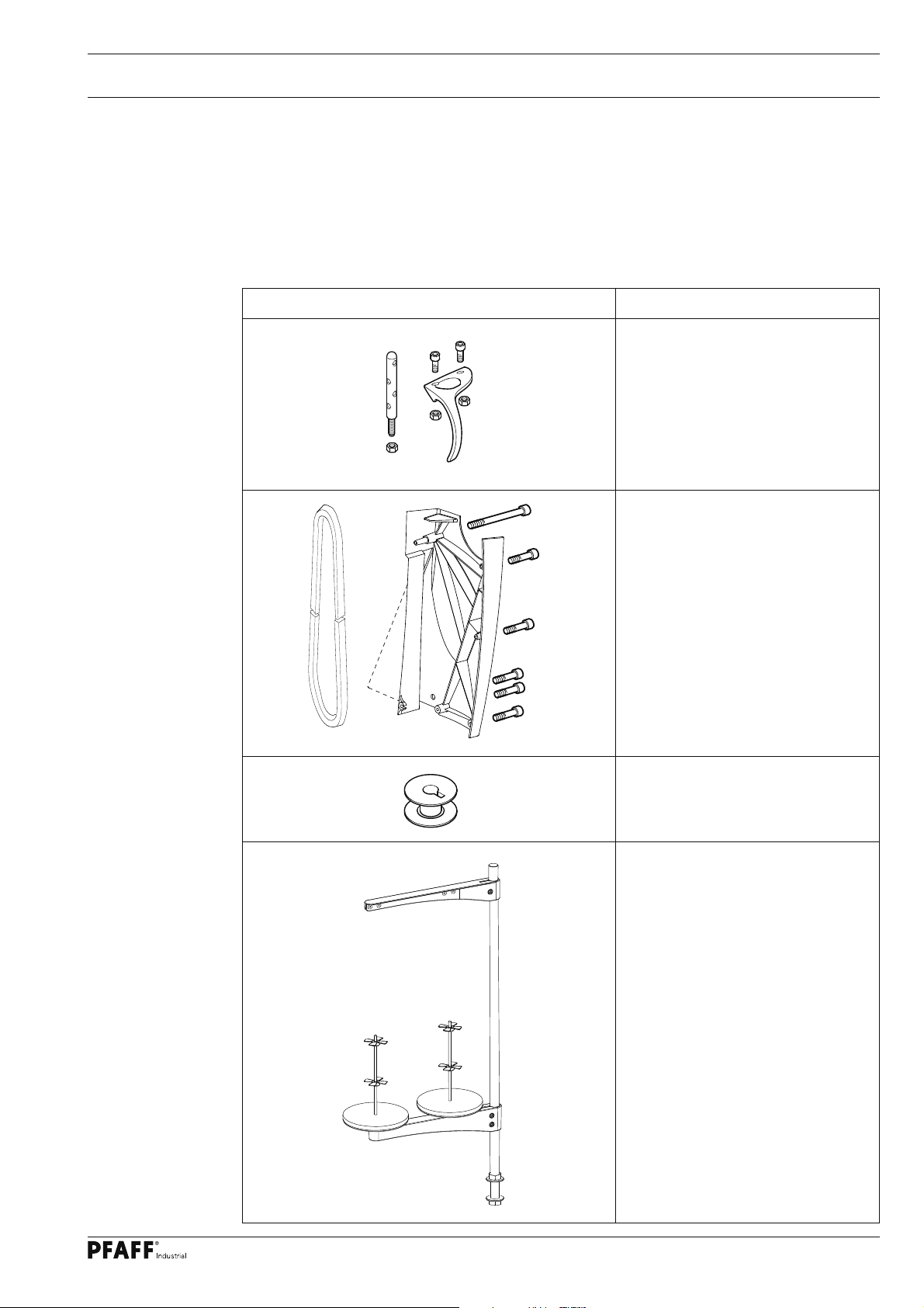
2.01 Sewing machine accessories
Sewing machine accessories Description / No. of pieces
Thread guide and take-up lever
guard with screws and nuts(1x)
V-belt and
belt guard with screws (1x)
Bobbin (5x)
Reel stand complete (1x)
5
Page 6
Scope of delivery
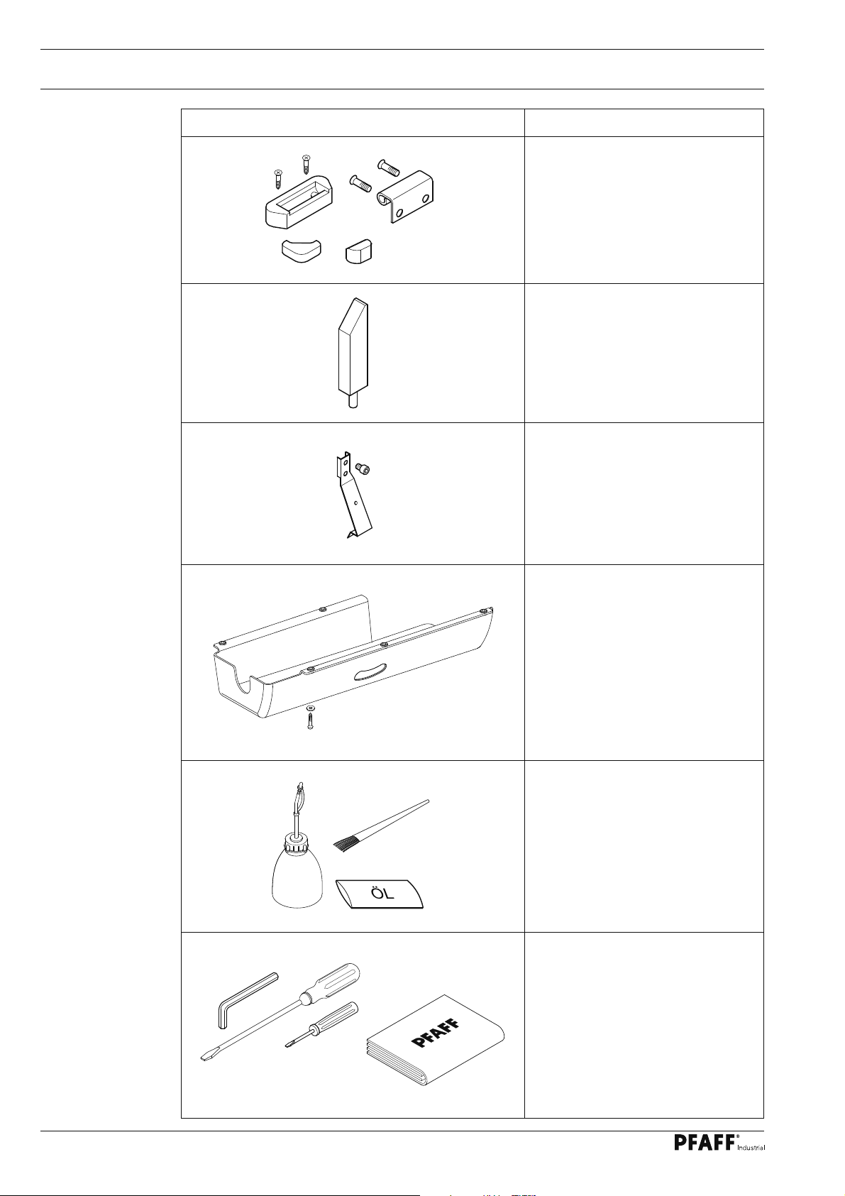
Sewing machine accessories Description / No. pieces
Rear rubber pads with screws (2x)
Front rubber pads (4x)
Hinge with screws (2x)
Sewing head support
Tilt lock (1x)
Oil pan with 5 screws and washers
Oilcan (1x),
Sachet with 80 ml oil,
Dusting brush (1x)
Allan key 3 mm (1x),
Screwdriver large (1x),
Screwdriver small (1x)
Sewing head protective cover
6
Page 7
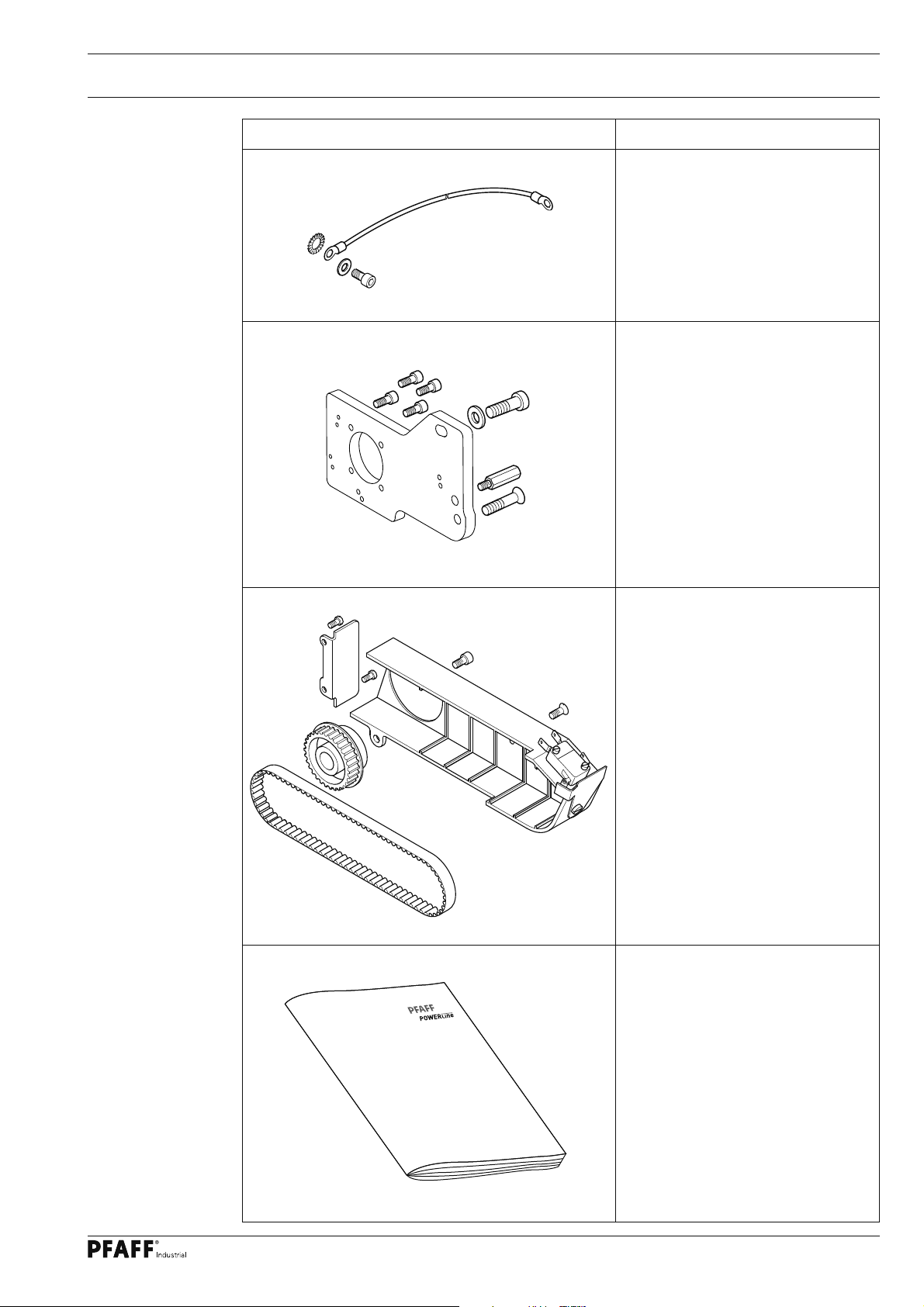
Sewing machine accessories Description / No. of pieces
Scope of delivery
Earth cable (3x) ,
Screw and washers
Motor bracket with fi xing screws
Drive wheel, drive belt, belt guard
and approach barrier switch with
Fixing screws
Set-up instructions,
instruction manual to the machine
7
Page 8

Scope of delivery
2.02 Accessories for the sewing machine drive EcoDrive P74 ED-L
Control package EcoDrive P74 ED-L Description
Motor
Control box with switch,
fastening screws and cable
Adapter cable for synchronizer
8
Page 9
Scope of delivery
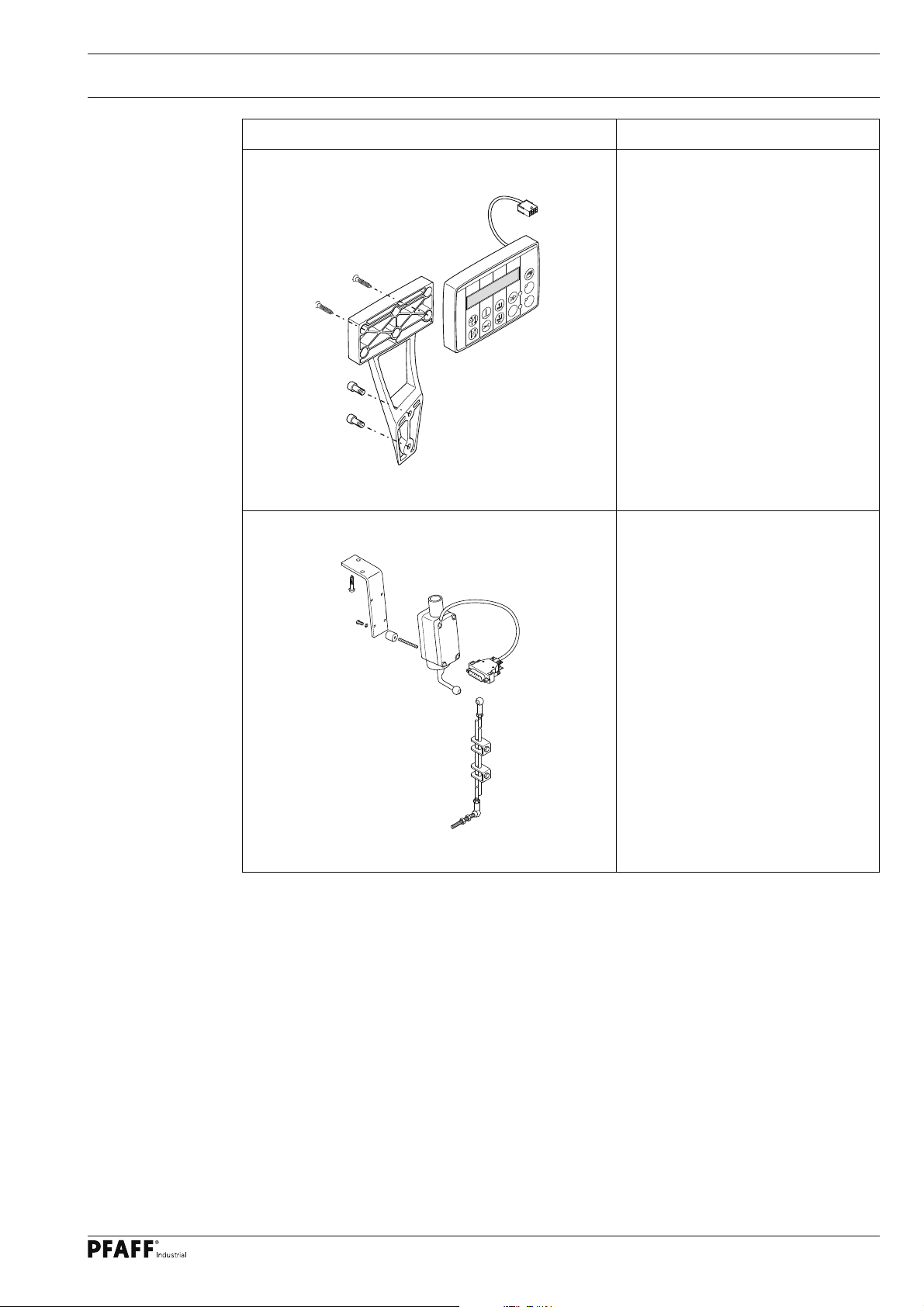
Control package EcoDrive P74 ED-L
B C D
A
TE
+
PM
-
F1
Description
Control panel bracket with control
panel and fastening screws
Speed control unit with holder
and fastening screws, and
connecting rod to the pedall
9
Page 10

Stand and table top
3 Stand and table top
3
.01 Table top cutout (PFAFF 2595 / 2596 PLUS with tilted work base)
B-B
(2x)
17 -0,5
AA
(2x)
R9
-0,5
B
4
B
0
A-A
115
R22
107
N.M.
+0,4
(2x)
14 0
(2x)
(2x)
14 0
+0,4
(4x)
R9
R23
(2x)
- 0,5
+0,4
50 0
R8
644
(4x)
(2x)
+0,4
50 0
(2x)
R1 5
10
209 0
+0,4
Page 11

Stand and table top
3.02 Table top cutout (PFAFF 2595 / 2596 BASIC + PLUS without tilted work base
17,5
0,5(2x)
-
B-B
AA
(2x)
R9
-0,5
B
A-A
0
(4x)
60°
-0,4 (2x)
(2x)
40
(4x)
R10
- 0,5
- 0,5
(4x)
R9
(2x)
66
+0,4 (2x)
(2x)
99
(2x)
77,3
233,5
40
+0,4 (2x)
208
644
B
562,50
80
92 364
18,7 - 0,5
+0,4 (2x)
14
115
R22
106
206 +0,4
(4x)
R9
(2x)
R23
+0,4 (2x)
14
(4x)
R8
- 0,5
(2x)
R15
+0,4 (2x)
50
+0,4 (2x)
50
11
Page 12

Stand and table top
3.03 Table top cutout (PFAFF 2595 / 2596 BASIC with clutch motor
- without tilted work base)
B-B
-0,5 (2x)
17, 5
A-A
517,5
46
B
60°
- 0,5
(4x)
240,5
(4x)
R 9
AA
60
30
5
+0,4 (2x)
233,5
(2x)
99
-0,5
B
644
906-4001-151
Vers. 08.04.08
12
- 0,5
- 0,4 (2x)
(2x)
80
92 364
18,7-0,5
0
20
40
(4x)
R 1 0
115
R 2 2
(2x)
66
(4x)
R 9
22
(2x)
77,3
106
80
+0,4
+0,4 (2x)
R 2 2
206
208
(4x)
R 9
(2x)
R 2 3
+0,4 (2x)
14
+0,4 (2x)
(4x)
R8
- 0,5
50
+0,4 (2x)
+0,4 (2x)
50
(2x)
R 1 5
14
Page 13

Stand and table top
3.04 Assembly drawing for the table top (PFAFF 2595 / 2596 PLUS
- with and without tilted work base)
100
Stand position
30
906-3750-010/895
7587
70
0 / 1
230
90 56
275,6
Controlbox P 321 P 74 ED-L
115
30
20
Speedcontrolunit
360
View:
Underside table top
13
Page 14

Installation
4 Installation
4
.01 Assembling the stand and table top
● Assemble the stand (part no. 906-3750-010/895) and table top as shown in the following
illustration.
The stand and table top must
be constructed for a weight of
at least 100 kg.
● When assembling the table top,
please observe the assembly drawing
(Chapter 3.04 ).
Stand
906-3750-010/895
4,2x13 (4x)
3x20 (6x)
4x30 (4x)
6x40 (4x)
Fig. 4 - 01
14
M10x20 (4x)
Page 15

Installation
4.02 Adjusting the table-top height
1
1
2
Fig. 4 - 02
● Loosen screw 1.
● Adjust the table tap to the required working height by increasing or reducing the height
of the stand and then level the table-top horizontally.
To avoid the stand tilting, adjust it evenly on both sides.
● To guarantee that the stand is standing securely, it must be positioned securely on the
ground with all four legs.
● The height can be adjusted with screw 2.
15
Page 16

Installation
4.03 Assembling the EcoDrive control unit P74 ED-L
Fig. 4 - 03
6x30 (4x)
6x30 (2x)
2
6x30 (2x)
6x30 (2x)
3
1
5
4
5
16
● Fit the control box 1 to the table top with four screws 6x30.
● Attach the mains switch 2 to the table top with two screws 6x30.
● Screw the mains cable of the control box 1 to the table top with a mains lead cleat.
● Assemble the speed control unit 3 and attach it to the table top with two screws 6x30.
● Mount the pedal on the stand’s cross-bar, aligning the middle of the pedal with the
centre of the needle.
● Fit connection rod 4 to speed control unit 3 and to the pedal.
● The slant of the pedal can be adjusted after loosening screw 6 (slant angle approx. 10°).
Page 17

Installation
4.04 Setting the sewing machine into the stand
1
Fig. 4 - 04
● Attach each of the hinges 1 to the sewing head with two screws M6 x 16.
● On the PFAFF 2595 and 2596 attach tilt lock 2 with a M5 x 6 screw.
● Set the se
wing machine into the t
able top.
2
17
Page 18

Installation
4.05 Assemble the mounted motor
6
3
8
7
5
A
4
B
A
B
B
2
10
9
10
A
A
B
AB
1
Fig. 4 - 05
● Fix bearing plate 1 on to motor 2 using screws 3, as shown in fi g. 4-05.
● Remove the wedge from motor shaft 4.
● Attach angle bracket 5 with screws 6.
● Mount drive belt wheel 7 onto motor shaft 4 so that screw 8 is positioned with the hub in
the drive shaft slot.
● Screw threaded bolts 9 into bearing plate 1.
● Use screw 10 ( Fig. 4 - 06 to fi x motor 2 bearing plate 1 to the machine housing.
Tighten screws 10 only a little.
The threaded bolts 9 and the screws 6 and 10 can be screwed into the
respective holes A or B depending on the table top:
Hole A = table top without tilt base
Hole B = table top with tilt base.
18
Page 19

Installation
4.06 Apply drive belt and tension
A
10
B
10
11
2
Version B
Fig. 4 - 06
● Lay on the drive belt 11 .
● Pivot the motor bearing plate 2 so that the drive belt 11 is taut.
Version A
● In this position, tightly fi x screw 10.
4.07 Mounting the belt guard of the fl ange motor
● Attach belt guard 1 with screws 2 and 3.
1
2
3
Fig. 4 - 07
19
Page 20

Installation
4.08 Connecting the safety switch
● Connect plug 1 of safety switch 2 as
shown in Fig. 4 - 08.
When the machine head is
tilted back,the safety switch
prevents the machine from star-
ting when the main switch is
on.
2
1
Fig. 4 - 08
4.09 Checking the start inhibitor function
● Switch the machine on at the main switch and tilt back the sewing head.
● The error message "Err: 9" must appear on the control panel.
● If the message does not appear, check the setting of safety switch 2.
● After the sewing head has been returned to the upright position, the machine is ready for
operation again.
20
Page 21

Installation
4.10 Assembling the LED lamp (optional)
2
5
4
1
Fig. 4 - 10
● Unscrew the head and arm cover.
3
1
● Remove the complete voltage mounting plate.
● Assemble the LED lamps 1 as shown in Fig. 4-10.
● Install cable 2 in the recess of the machine arm and lead plug 3 down through the
machine.
● Secure cable 2 with clamps 4 and 5 and the corresponding available screw.
● Reattach the voltage mounting plate and head and arm cover.
21
Page 22

Installation
4.11 Fitting the transformer to the LED lamp
4x20 (4x)
Fig. 4 - 11
● Attach transformer 1 to the table top with four screws 4 x 20.
● Screw the power line with clamps and main leads cleat to the table top.
● Connect the cable to the LED lamp with a connector.
22
Page 23

Installation
4.12 Assembling the thread guide and take-up lever guard
2
3
3
1
5
6
4
10
8
7
9
11
Fig. 4 - 12
● Remove face plate 1 and arm cover 2 (screws 3).
● Adjust thread guide 4 (screw 5) as shown in Fig. 4 - 12.
● Insert thread guide 6 in hole 7, and fasten with nut 8 from below.
● Attach take-up lever guard 9 with bolts 10 (M4 x 10) and nuts 11 to arm cover 2.
Leave face plate and arm cover unscrewed for the next assembly steps.
23
Page 24

Installation
4.13 Assembling the top V-belt guard and sewing head support
2
3
2
1a
1
2
Fig. 4 - 13
● Attach guard belt 1 (for machines with transmission motor add protector 1a) with screws 2.
● Insert sewing head support 3 into the hole in the table top.
Do not operate the machine with support 3! Danger from top-heavy
sewing head! Machine cannot fall over when tilted backwards!
24
Page 25

Installation
4.14 Mounting the control panel
3
4
1
2
6
5
Fig. 4 - 14
● Fasten the control panel bracket 2 to the threaded holes 1 with two screws M5 x 12.
● Attach control panel 3 to bracket 2 with two screws 5 x 10.
● Lead the control panel cable through hole 4 in the case.
● Connect the control panel plug with the connector provided for the control panel in the
arm of the machine.
● Reattach face plate 5 and arm cover 6.
25
Page 26

Installation
4.15 Connecting the plug-in connections and earth cables
EcoDrive P74-ED-L
B
Fig. 6 - 06
X1
A
M6x16
X2
X4
X7
X3
X6
X2
1
X2.1
X5
X2.2
26
● Connect all plugs as labelled on the control box 1
● In the case of control unit EcoDrive P74 ED-L the adapter cable X2 is to be connected to
socket X2. Plug X2.1 is to be connected to the motor and plug X2.2. to the synchronizer.
● The following ground cables must be attached in order to discharge static electricity.
● Connect the earth cable from the superstructure (480 mm)to the earthing connection A.
● Join earthing connection A andearthing connection B with the earth cable (700 or 100 mm).
● Connect the earthing connection on the motor base with earthing connection A with the
earth cable (700 mm)
● On control P74 ED-L connect main switch and earthing connection A with the earth cable
(500 mm).
● Fasten the earth cable from plug X1 to earth point B.
Page 27

Installation
4.16 Block diagram PFAFF 2595/96 PLUS with EcoDrive P74 ED-L
Optional
Light
barrier
A20
Y3, Y4, Y5, Y6, Y9
Y8, Y14, Y1X, R1
XA20
Option
2595 PLUS
2596 PLUS
XS27
XS29
S26
Ministop drive
unit (long) with
incremental
transducer
Synchronizer PD 6
BDF - PICO TOP
LED
power
supply
unit
A2
PC
X7
Control unit P74 ED
A1
X3
S1.1
X5
KS
X1
X2
X2.1
X2
Q1
Power switch
Mains plug
X2.2
X2.2
X4
for
software
download
X0
27
Page 28

Installation
4.17 Mounting / connecting the maintenance unit
1
Fig. 4 - 17
● Attach maintenance unit 1 to the stand with two screws M6 x 25.
● Connect the maintenance unit to the machine’s pneumatic tube.
To ensure the perfect functioning of all pneumatic devices, there must be a supply system pressure of between 8 and 10 bar.
The operating pressure is 6 bar (also see Chapter 9 Care and Maintenance of
the Service Manual).
28
Page 29

Commissioning
5 Commissioning
Before commissioning the machine, it must be thoroughly cleaned and then
oiled., see chapter 9 Care and maintenance in the instruction manual.
● Check the machine, particularly its electrical wiring and pneumatic tube
connections, for any damage.
● Have skilled personnel check if the machine can be operated with the available mains vol-
tage.
Do not operate the machine if there is any discrepancy.
The machine may only be connected to an earthed socket!
5.01 Switching the machine on/off
● Switch the machine on (see Chapter 7.01, On/off switch in the instruction manual).
29
Page 30

PFAFF Industriesysteme
und Maschinen AG
Hans-Geiger-Str. 12 - IG Nord
D-67661 Kaiserslautern
Phone: +49 - 6301 3205 - 0
Fax: +49 - 6301 3205 1386
E-mail: info@pfaff-industrial.com
Hotlines:
Technical service: +49 - 175/2243-101
Application consultance: +49 - 175/2243-102
Spare-parts hotline: +49 - 175/2243-103
Printed in Germany
© PFAFF Industriesysteme und Maschinen AG 2009, PFAFF is the exclusive trademark of VSM Group AB.PFAFF Industriesysteme und Maschinen AG is an authorized licensee of the PFAFF trademark.
 Loading...