

Pfaff POWERLINE 2571 ME PLUS, POWERLINE 2574 ME PLUS, POWERLINE 2591 ME PLUS Instruction Manual
Page 1

2571 ME PLUS
2574 ME PLUS
INSTRUCTION MANUAL
2591
ME PLUS
This instruction manual applies to machines
from software version 0389/001 and serial
number 2 766 760 onwards
296-12-19 128/002
Betriebsanleitung engl. 02.11
Page 2

This Instruction Manual is valid for all models and subclasses listed in the
chapter "Specifi cations".
The adjustment manual for the machines can be downloaded free of
charge from the internet address
www.pfaff-industrial.com/pfaff/de/service/downloads
As an alternative to the internet download the adjustment manual can also be
ordered in book form under part no. 2296-12-19 129/002.
The reprinting, copying or translation of PFAFF Instruction Manuals, whether in whole or
in part, is only permitted with our previous authorization and with written reference to the
source.
PFAFF Industriesysteme
und Maschinen AG
Hans-Geiger-Str. 12 - IG Nord
D-67661 Kaiserslautern
Page 3

Index
Contents ..................................................................................Page
1 Safety .................................................................................................................................... 5
1.01 Directives .............................................................................................................................. 5
1.02 General notes on safety .........................................................................................................5
1.03 Safety symbols ......................................................................................................................6
1.04 Important points for the user ................................................................................................. 6
1.05 Operating and specialist personnel ........................................................................................7
1.05.01 Operating personnel .............................................................................................................. 7
1.05.02 Specialist personnel ............................................................................................................... 7
1.06 Danger warnings .................................................................................................................... 8
2 Proper use............................................................................................................................. 9
3 Specifi cations ..................................................................................................................... 10
3.01 PFAFF 2571 ME, 2574 ME, 2591 ME .................................................................................. 10
3.02 Machine equipment and options ......................................................................................... 11
4 Disposal of Machine .......................................................................................................... 12
5 Transportation, packing and storage ................................................................................ 13
5.01 Transportation to customer‘s premises ............................................................................... 13
5.02 Transportation inside the customer‘s premises ................................................................... 13
5.03 Disposal of packing materials ..............................................................................................13
5.04 Storage ................................................................................................................................ 13
6 Explanation of symbols ..................................................................................................... 14
7 Controls .............................................................................................................................. 15
7.01 On/off switch / Sewing lamp switch (option) ...................................................................... 15
7.02 Pedal .................................................................................................................................... 15
7.03 Keyboard on machine head .................................................................................................. 16
7.04 Swivel out the roller-presser ................................................................................................ 17
7.05 Knee lever ............................................................................................................................ 17
7.06 Switchable needle thread tension ........................................................................................ 18
7.07 Edge trimmer -725/04 for 2571 ME ..................................................................................... 19
7.08 Edge trimmer -725/04 for 2591 ME ..................................................................................... 20
7.09 Control panel ........................................................................................................................ 21
7.09.01 Selection keys ......................................................................................................................21
7.09.02 Function keys ....................................................................................................................... 22
8 Preparation ........................................................................................................................ 24
8.01 Inserting the needle ............................................................................................................ 24
8.02 Winding the bobbin thread, regulating the winder tension ..................................................25
8.03 Removing/Inserting the bobbin case ................................................................................... 26
8.04 Threading the bobbin case/Adjusting the bobbin thread tension .........................................26
Page 4

Index
Contents ..................................................................................Page
8.05 Threading the needle thread and regulating its tension on model 2571 and 2591 ME .......27
8.06 Threading the needle thread and regulating its tension on model 2574 ME ........................28
8.07 Setting the stitch length ............................................................................................................29
8.08 Switching the sewing functions on / off ............................................................................... 29
8.09 Entering start and end backtack stitches ..................................................................................30
8.10 Enter / change template code .............................................................................................. 31
8.11 Bobbin thread control........................................................................................................... 33
9 Sewing ................................................................................................................................ 35
9.01 Manual sewing..................................................................................................................... 35
9.01.01 Turning sewing functions on/off ...........................................................................................36
9.01.02 Changing number of backtack stitches ................................................................................ 36
9.01.03 Selecting parameter entry ................................................................................................... 37
9.01.04 Selecting the maximum speed ............................................................................................37
9.02 Programmed Sewing ........................................................................................................... 38
9.03 Error Messages.................................................................................................................... 39
10 Input .................................................................................................................................... 40
10.01 Programming sewing ........................................................................................................... 40
10.02 List of parameters for control P320 / P321 .......................................................................... 43
10.03 Error Messages and Description.......................................................................................... 48
10.04 Motor Errors......................................................................................................................... 49
11 Care and maintenance ....................................................................................................... 50
11 .01 Servicing and maintenance intervals ................................................................................... 50
11 .02 Cleaning the machine ..........................................................................................................50
11 .03 Oiling the hook ..................................................................................................................... 51
11 .04 Monitoring the oil level for clamp and head pieces..............................................................51
11 .05 Lubricating the bevel gears .................................................................................................. 52
11 .06 Cleaning the blower air fi lter ................................................................................................52
12 Wearing parts ..................................................................................................................... 53
Page 5

Safety
1 Safety
1
.01 Directives
This machine is constructed in accordance with the European regulations contained in the
conformity and manufacturer’s declarations.
In addition to this Instruction Manual, also observe all generally accepted, statutory and
other regulations and legal requirements and all valid environmental protection regulations!
The regionally valid regulations of the social insurance society for occupational accidents or
other supervisory organizations are to be strictly adhered to!
1.02 General notes on safety
● This machine may only be operated by adequately trained operators and only after having
completely read and understood the Instruction Manual!
● All Notes on Safety and Instruction Manuals of the motor manufacturer are to be read be-
fore operating the machine!
● The danger and safety instructions on the machine itself are to be followed!
● This machine may only be used for the purpose for which it is intended and may not be
operated without its safety devices. All safety regulations relevant to its operation are to
be adhered to.
● When exchanging sewing tools (e.g. needle, roller presser, needle plate and bobbin),
when threading the machine, when leaving the machine unattended and during mainte-
nance work, the machine is to be separated from the power supply by switching off the
On/Off switch or by removing the plug from the mains!
● Everyday maintenance work is only to be carried out by appropriately trained personnel!
● Repairs and special maintenance work may only be carried out by qualifi ed service staff
or appropriately trained personnel!
● Work on electrical equipment may only be carried out by appropriately trained personnel!
● Work is not permitted on parts and equipment which are connected to the power supply!
The only exceptions to this rule are found in the regulations EN 50110.
● Modifi cations and alterations to the machine may only be carried out under observance
of all the relevant safety regulations!
● Only spare parts which have been approved by us are to be used for repairs! We express-
ly point out that any replacement parts or accessories which are not supplied by us have
not been tested and approved by us. The installation and/or use of any such products can
lead to negative changes in the structural characteristics of the machine. We are not liable
for any damage which may be caused by non-original parts.
5
Page 6
Safety
1.03 Safety symbols
Danger!
Points to be observed.
Danger of injury for operating and specialist personnel!
Do not operate without fi nger guard and safety devices.
Before threading, changing bobbin and needle, cleaning
etc. switch off main switch.
I
Caution
1.04 Important points for the user
● This Instruction Manual is an integral part of the machine and must be available to the
operating personnel at all times.
● The Instruction Manual must be read before operating the machine for the fi rst time.
● The operating and specialist personnel is to be instructed as to the safety equipment of
the machine and regarding safe work methods.
● It is the duty of the user to only operate the machine in perfect running order.
● It is the obligation of the user to ensure that none of the safety mechanisms are removed
or deactivated.
● It is the obligation of the user to ensure that only authorized persons operate and work
on the machine.
Further information can be obtained from your PFAFF agent.
6
Page 7

Safety
1.05 Operating and specialist personnel
1
.05.01 Operating personnel
Operating personnel are persons responsible for the equipping, operating and cleaning of
the machine as well as for taking care of problems arising in the sewing area.
The operating personnel is required to observe the following points and must:
● always observe the Notes on Safety in the Instruction Manual!
● never use any working methods which could adversely affect the safety of the machine!
● not wear loose-fi tting clothing or jewelery such as chains or rings!
● also ensure that only authorized persons have access to the potentially dangerous area
around the machine!
● always immediately report to the person responsible any changes in the machine which
may limit its safety!
1.05.02 Specialist personnel
Specialist personnel are persons with a specialist education in the fi elds of electrics, electro-
nics and mechanics. They are responsible for the lubrication, maintenance, repair and adjust-
ment of the machine.
The specialist personnel is obliged to observe the following points and must:
● always observe the Notes on Safety in the Instruction Manual!
● switch off the On/Off switch before carrying out adjustments or repairs, and ensure that
it cannot be switched on again unintentionally!
● wait until the luminous diode on the control box is no longer blinking or on before begin-
ning adjustment or repair work.
● never work on parts which are still connected to the power supply! Exceptions are ex-
plained in the regulations EN 50110.
● replace the protective coverings and close the electrical control box afer all repairs or
maintenance work!
7
Page 8
Safety
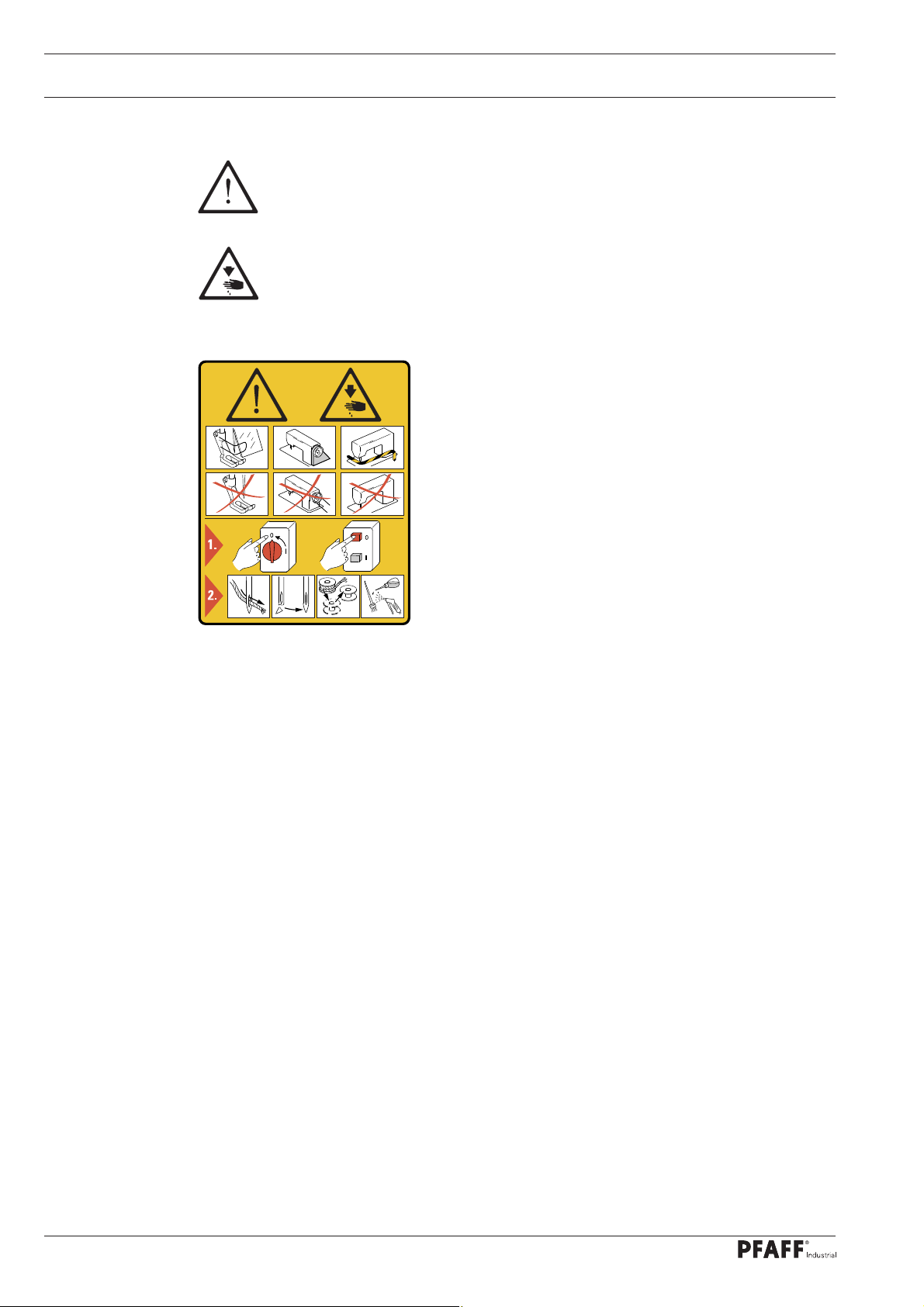
1.06 Danger warnings
A working area of 1 m must be kept free both in front of and behind the machi-
ne, so that easy access is possible at all times.
Never put your hands or fi ngers in the sewing area during sewing!
Danger of injury by the needle!
While setting or adjusting the machine do not leave any objects on the table nor
in the needle plate area! Objects may be trapped or fl ung out of the machine!
1
2
Fig. 1 - 01
5
4
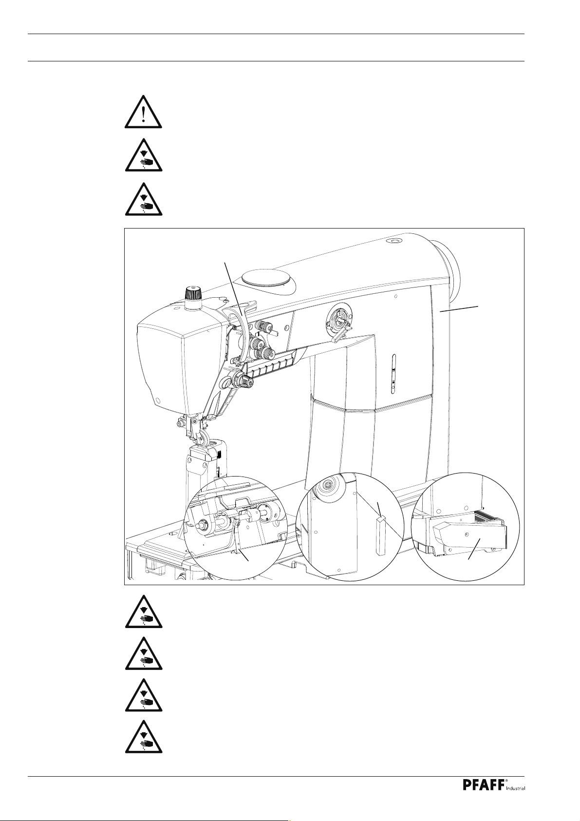
Do not run the machine without take-up lever guard 1!
Danger of injury by moving take-up lever!
Do not operate machine without cover 2 and belt guard 3!
Risk of injury from moving parts!
Do not operate the machine without tilt lock 4!
Danger of crushing between sewing head and table!
Do not operate the machine without support 5! Danger due to top-heavy
sewing head! Machine can tip over backwards when tilted!
3
8
Page 9

Proper use
2 Proper use
The PFAFF 2571 ME and PFAFF 2591ME are high-speed, single-needle postbed sewing
machines with a forwards and reverse feeding feed wheel and roller presser and needle
feed.
PFAFF 2571 ME Post to the left of the needle.
PFAFF 2591 ME Post to the right of the needle.
The PFAFF 2574 ME is a high-speed, two-needle postbed sewing machines with a forwards
and reverse feeding feed wheel and roller presser.
The machines are used for sewing lockstitch seams in the leather and upholstery industries.
Any and all uses of this machine which have not been approved of by the
manufacturer are considered to be inappropriate! The manufacturer cannot be
held liable for any damage caused by the inappropriate use of the machine!
The appropriate use of the machine includes the observance of all operational,
adjustment, maintenance and repair measures required by the manufacturer!
9
Page 10

Specifi cations
3 Specifi cations *
3
.01 PFAFF 2571 ME, 2574 ME, 2591 ME
Stitch type: ..........................................................................................................301 (lockstitch)
Needle system:
2571, 2591 ........................................................................................................................... 134
2574 .............................................................................................................................. 134 - 35
Model: ............................................................................................................................. A, B, C
Needle thickness in 1/100 mm:
Model A: ................................................................................................................................ 70
Model B: ............................................................................................................................. 100
Model C: ............................................................................................................................. 130
Stitch length max.: .........................................................................................................5,0 mm
Thread thickness max. ( Synthetiks ):
Model A: .......................................................................................................................... 60/3
Model B: .......................................................................................................................... 40/3
Model C: .......................................................................................................................... 15/3
Clearance under roller presser: .........................................................................................7 mm
Clearance width: ...........................................................................................................345 mm
Clearance height: ..........................................................................................................290 mm
Post height: ................................................................................................................... 180 mm
Max. speed:
PFAFF 2571, 2591 Ausführung A + B .....................................................................3500 spm
PFAFF 2574 Ausführung A + B ............................................................................... 2600 spm
PFAFF 2574, 2591 Ausführung C ............................................................................2000 spm
Cutting depth (for –725/..): ....................................................................................0.8 – 2.5 mm
Cutting speed (for –725/..):................................................................................. 2800 cuts/min.
Noise data:
Emission level at workplace at appropriate speed
(Noise measurement in accordance with DIN 45 635-48-A-1, ISO 11204, ISO 3744, ISO 4871)
model A + B at a speed of 2800 spm.: ............................................................ LpA = 80 dB(A)
model C at a speed of 1600 spm.: ................................................................... LpA = 74 dB(A)
▲
▲
▲
X
X
X
■
■
10
Connection data:
Operating voltage: ................................................................................ 230 V ± 10%, 50/60 Hz
Max. power consumption: ............................................................................................. 1.2 kVA
Fuse protection: ................................................................................................... 1 x 16 A, inert
Leakage current: .......................................................................................................< 5 mA **
Net weight of sewing head: ..................................................................................approx. 87 kg
Gross weight of sewing head: ..............................................................................approx. 97 kg
❋
Subject to alteration
❋ ❋
Due to the use of network fi lters there is a nominal leakage current of < 5 mA.
X
Dependent on material, work operation and stitch length
▲
or similar strengths of other types of thread
■
KpA = 2,5 dB
Page 11

Specifi cations
3.02 Machine equipment and options
Vetical hook
Thread trimmer (-900/81), < 13 mm thread ends
Presser foot lift (-910/..), electromagnetic
Knuckle switch manual locking
Automatic backtacking (-911/..)
Oil level control through inspection glass
Roller-presser pressure, manually adjustable
DC-motor functionality
Control panel - PicoT
Integrated multiple switch on mac
Integrated LED sewing lamp on sewing head, dimmable
Bobbin thread winding device
Edge trimmer -725/.. (only on the 2571 and 2591)
op
hine head
●
●
●
●
●
●
●
●
●
●
●
●
❍
● = Standard, ❍ = Option
11
Page 12

Disposal of Machine
4 Disposal of Machine
● Proper disposal of the machine is the responsibility of the customer.
● The materials used for the machine are steel, aluminium, brass and various plastic
materials. The electrical equipment comprises plastic materials and copper.
● The machine is to be disposed of according to the locally valid pollution control regula-ti-
ons; if necessary, a specialist ist to be commissioned.
Care must be taken that parts soiled with lubricants are disposed of separately
according to the locally valid pollution control regulations!
12
Page 13

Transportation, packing and storage
5 Transportation, packing and storage
5
.01 Transportation to customer‘s premises
The machines are delivered completely packed.
5.02 Transportation inside the customer‘s premises
The manufacturer cannot be made liable for transportation inside the customer‘s premises
nor to other operating locations. It must be ensured that the machines are only transported
in an upright position.
5.03 Disposal of packing materials
The packing materials of this machine comprise paper, cardboard and VCE fi bre. Proper dis-
posal of the packing material is the responsibility of the customer.
5.04 Storage
If the machine is not in use, it can be stored as it is for a period of up to six months, but It
should be protected against dust and moisture.
If the machine is stored for longer periods, the individual parts, especially the surfaces of
moving parts, must be protected against corrosion, e.g. by a fi lm of oil.
13
Page 14
Explanation of symbols
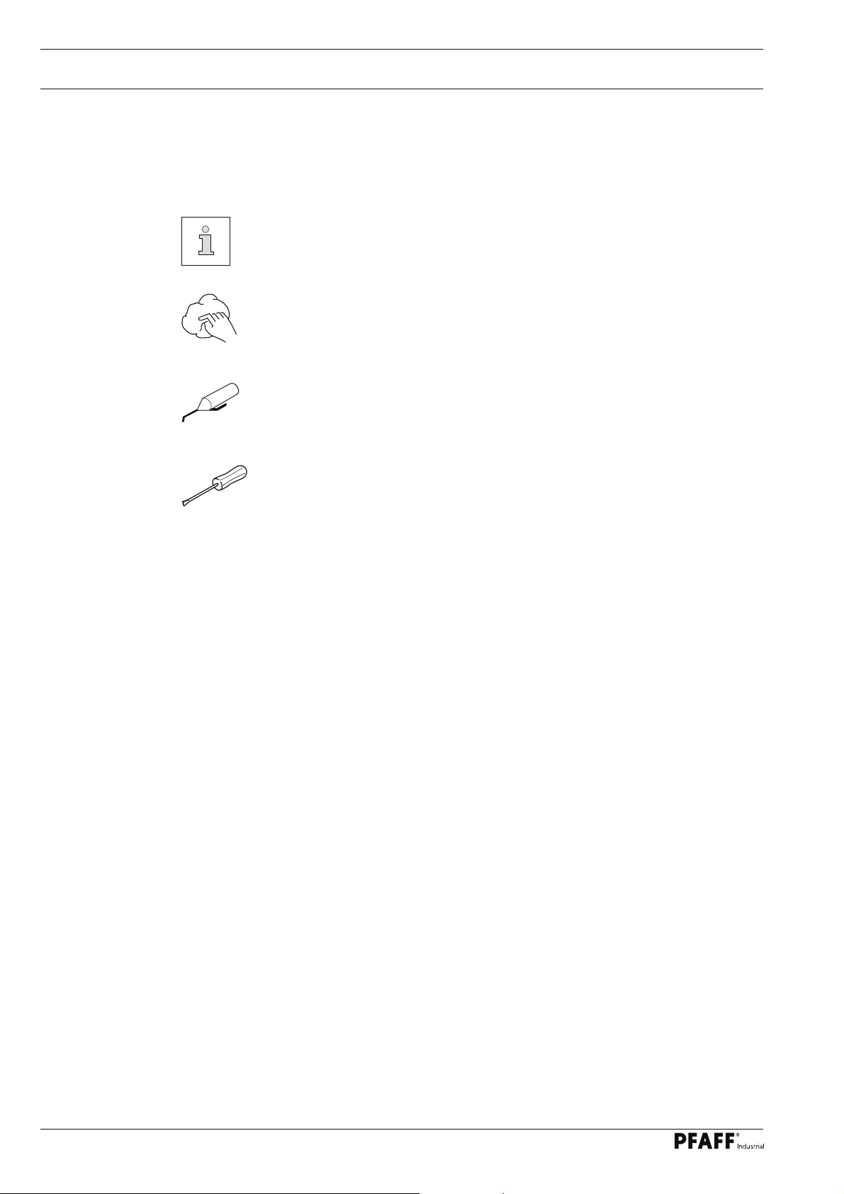
6 Explanation of symbols
In this instruction manual, work to be carried out or important information is accentuated by
symbols. These symbols have the following meanings:
Note, information
Cleaning, care
Lubrication
Maintenance, repairs, adjustment, service work
(only to be carried out by technical staff)
14
Page 15
Controls
7 Controls
7
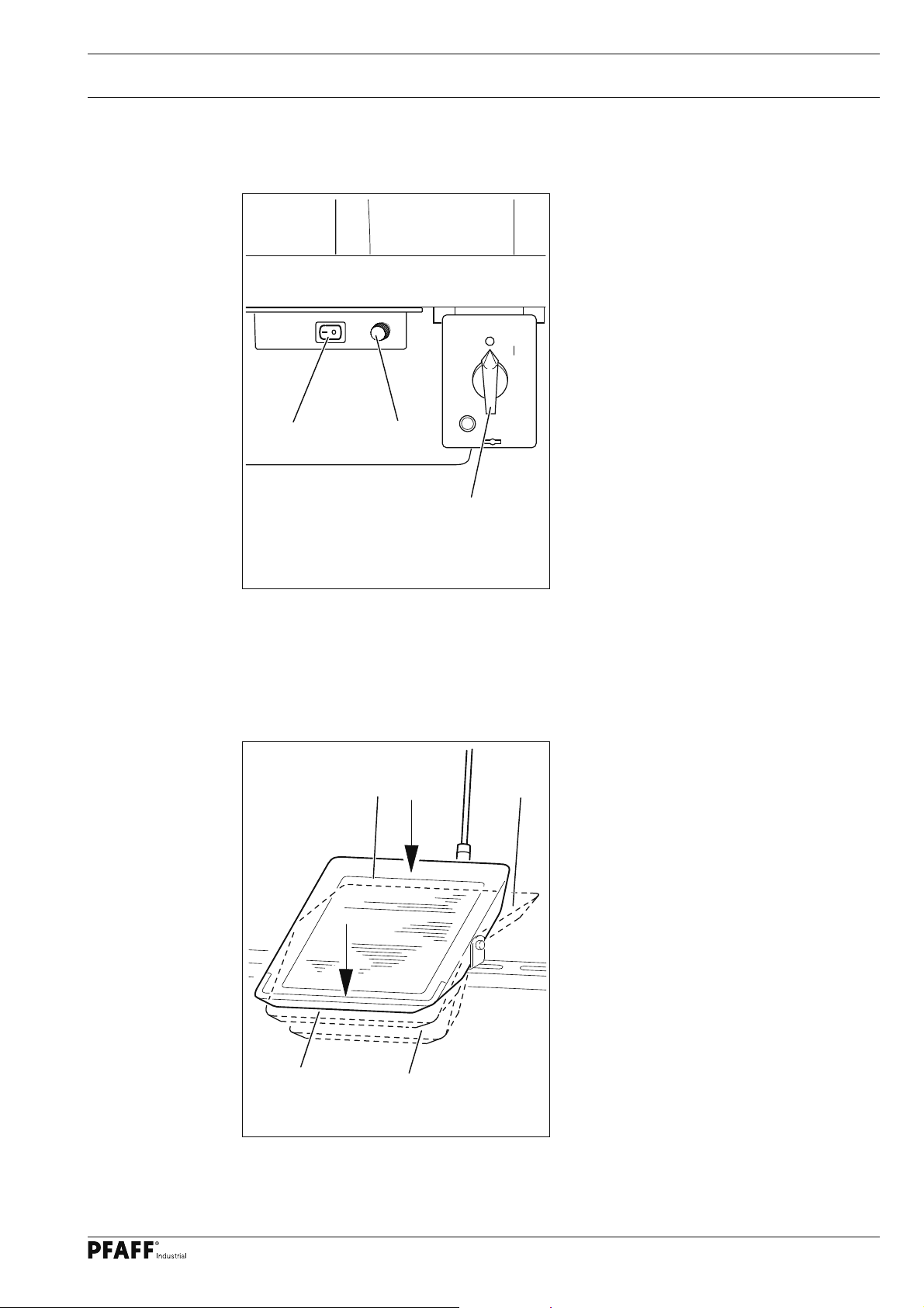
.01 On/off switch / Sewing lamp switch (option)
● To switch the control system of the
machine on or off, turn main switch 1.
● Switch the sewing lamp, which is inte-
grated in the machine head, on or off by
operating switch 2.
● Switch 3 regulates the brightness of the
sewing lamp.
Fig. 7 - 01
7.02 Pedal
1
2
3
● With the on/off switch on
0 +1
0 = Machine stop
+1 = Sew
- 1 = Raise roller presser
- 2 = Trim thread
-1 -2
Fig. 7 - 02
15
Page 16
Controls
7.03 Keyboard on machine head
1
Fig. 7 - 03
● The machine as a keyboard with 4 keys to activate different functions.
● When the keys 1 – 4 are operated on the standard version, the functions listed below are
carried out.
Key 1: Reverse sewing or intermediate backtacks during the seam (Standard)
Key 2: Needle position change / Half stitch
In setting 203, this button can be allocated to the following functions:
1 = Half stitch, 2 = Needle position change, 3 = Knee switch
Key 3: Needle position change / Single stitch
In setting 204 this button can be allocated to the following functions:
1 = Single stitc
Key 4: EMERGENCY key
Needle rises without thread trimming, thread tension is released, roller presser is
raised and the motor start inhibitor is activated. If the key is operated again, the
motor start inhibitor is deactivated.
h, 2 = Needle position change, 3 = Knee switch
3
2
4
16
Page 17
Controls
7.04 Swivel out the roller-presser
● In the raised position the roller-presser
1 can be swivelled out by gently pulling
downwards.
1
Fig. 7 - 04
7.05 Knee lever
1
● Operate knee lever 1 to raise the roller
presser.
Fig. 7 - 05
17
Page 18

Controls
7.06 Switchable needle thread tension
● The needle thread tension can be increa-
sed by turning lever 1 to the right.
1
Fig. 7 - 06
18
Page 19

Controls
7.07 Edge trimmer -725/04 for 2571 ME
Keep your hands away from the
Fig. 7 - 07
4
2
3
Switch on knife drive:
6
5
1
● Move lever 1 backwards. The knife
moves into operating position.
Switch off knife drive:
● Press lever 1. The knife swings back-
wards.
Switch on edge guide:
● Swing edge guide 2 into position by
hand and press lever 3. The edge guide 2
moves into its operating position.
Switch off edge guide:
● Raise edge guide 2 and let it click into
position. The edge guide 2 is out of
operation.
moving knife! Danger of injury!
● Raise lever 4. The edge guide swings
backwards.
Changing the knife:
The following work may only be carried out by technical staff or by
persons who have been properly instructed.
● Switch off the machine.
● Loosen screw 5 and remove knife 6.
● Insert new knife and slightly tighten screw 5.
● Adjust the knife according to Chaper 1.06.05 Cutting stroke and tighten screw 5.
19
Page 20

Controls
7.08 Edge trimmer -725/04 for 2591 ME
4
2
3
1
Fig. 7 - 08
Keep your hands away from the moving knife! Danger of injury!
Switch on knife drive:
● Move lever 1 backwards. The knife moves into operating position.
6
5
7
Switch off knife drive:
● Press lever 1. The knife swings backwards.
Switch on edge guide:
● Swing edge guide 2 into position by hand and press lever 3. The edge guide 2 moves
into its operating position.
Switch off edge guide:
● Raise edge guide 2 and let it click into position. The edge guide 2 is out of operation.
● Raise lever 4. The edge guide swings backwards.
Changing the knife:
The following work may only be carried out by technical staff or by
persons who have been properly instructed.
● Switch off the machine.
● Loosen screw 5 and remove knife 6.
● Insert new knife and push it close to needle plate insert 7.
● Slightly tighten screw 5.
20
● Adjust the knife according to Chaper 1.06.07 Knife position and tighten screw 5.
Page 21

Controls
7.09 Control panel
The control panel is used to display and call up the machine functions for setting up and for
sewing operation, for entering parameter values and for reading error messages and service
settings.
1
2
3
Fig. 6 - 03
The control panel has the following operating and display elements:
● The display 1 consists of a one-line display with an 8-fi gure LCD-matrix and is used to
show appropriate information and selection parameter.
● The selection keys 2 are used to change the screen display, to switch the function keys
and to select the operating mode (manual / programmed sewing).
● The function keys 3 below the display are used to switch the appropriate functions on or
off, depending which key is selected, or to change the values of the appropriate setting
range (A, B, C or D).
7.09.01 Selection keys
The functions of the selections keys 2 are described in detail below:
Scrolling
● This selection key is used to change between the different menus shown on the display.
The selection of the menu and the setting values shown depend on the selection of the
operating mode, also see Chapter 9.01 Manual sewing or Chapter 9.02 Programmed
sewing.
TE / input
● This selection key is used to switch the function keys 3, also see Chapter 7.09.02 Func-
tion keys:
When this function is switched off (LED off), the appropriate sewing function can be
switched on or off with the function keys 3.
When this function is switched on (LED on), the set values of the appropriate setting
ranges (A, B, C and D) can be altered.
● Error correction can be cancelled by pressing this button, see
Chapter 9.03 Error Messages.
21
Page 22

Controls
7
.09.02 Function keys
TE / Input off TE / Input on
PM / operating mode
● Press this selection key to switch between manual sewing and programmed sewing.
When the LED is illuminated, the programmed sewing mode is activated.
The function keys 3 described below generally have two basic functions:
● To switch the sewing function on or off (LED in the "TE/Input" key is off)
An activated function is always shown by the corresponding illuminated LED.
● To alter the set values shown on the display (LED in the "TE/Input" key is on)
Press and hold the appropriate function key to slowly change the set value shown above
it. If the function key is pressed longer, the set value changes more quickly.
Description of the individual functions:
Start bartack / A+
● If the "TE / Input" key is switched off, the bartacks at the beginning of the seam (start
bartacks) are switched on or off, see Chapter 9.01.02 Entering bartack stitches.
● If the "TE / Input key" is switched on, this function key serves as a plus function for the
setting range (A).
End bartack / A-
● If the "TE / Input" key is switched off, the bartacks at the end of the seam (end bartacks)
are switched on or off, see Chapter 9.01.02 Entering bartack stitches.
22
● If the "TE / Input key" is switched on, this function key serves as a minus function for the
setting range (A).
Raised needle position after sewing stop / B+
● If the "TE / Input" key is switched off, the "raised needle position after sewing stop" func-
tion is switched on or off. If the function is switched on, the needle positions in t.d.c.
take-up lever after sewing stops
● If the "TE / Input key" is switched on, this function key serves as a plus function for the
setting range (B).
Page 23

Controls
Thread trimming / B-
● If the "TE / Input key" is switched off, the thread trimmer is switched on or off.
● If the "TE / Input key" is switched on, this function key serves as a minus function for the
setting range (B).
Raised foot position after sewing stop / C+
● If the "TE / Input key" is switched off, the "raised foot position after sewing stop" function
is switched on or off. If the function is switched on, the sewing foot is raised after sew-
ing stops.
● If the "TE / Input key" is switched on, this function key serves as a plus function for the
setting range (C).
Raised foot position at end of seam sector / C-
● If the "TE / Input key" is switched off, the "raised foot position at end of seam sector"
function is switched on or off. If the function is switched on, the sewing foot is raised at
the end of the seam sector.
● If the "TE / Input key" is switched on, this function key serves as a minus function for the
setting range (C).
F1 / D-
● If the "TE / Input" key is turned off, depending on the setting in parameter 205 the back-
tack suppression or raise needle without trimming function can be turned on.
● If the "TE / Input" key is turned off, this function key works as minus function for setting
ranges (D-).
23
Page 24

Setting up
8 Preparation
8.01 Inserting the needle
All regulations and instructions in this Instruction Manual are to be observed!
Special attention is to be paid to the safety regulations!
All preparation work is only to be carried out by appropriately trained personnel.
Before all preparation work, the machine is to be separated from the electricity
supply by removing the plug from the mains or switching off the On/Off switch!
1
2
Fig. 8 - 01
Switch off the machine!
Danger of injury due to unintentional starting of the machine!
Only use needles from the system intended for the machine,
see Chapter 3 Specifi cations.
PFAFF 2571 and 2591
● Raise the roller presser 1 and swing it
out.
● Loosen screw 2 and insert the needle
as far as possible. The long groove must
face to the right on model 2571 and to
the left on model 2591.
● Tighten screw 2 and swing roller presser
1 back into position.
2
1
Fig. 8 - 01a
PFAFF 2574
● Raise the roller presser 1 and swing it
out.
● Loosen screws 2 and insert the needles
so that the long groove of the left needle
is facing right, and that of the right need-
le is facing left.
● Tighten screws 2 and swing roller
presser 1 back into position.
2
24
Page 25

Setting up
8.02 Winding the bobbin thread, regulating the winder tension
1
2
3
4
5
6
7
Fig. 8 -02
● Draw the thread from the reel stand through guide hole 1 into the bobbin winder tension
unit 2 and then behind the thread clamp 3.
● Cut off the thread in thread clamp 3. The thread is retained.
● Place empty bobbin 4 on the bobbin winder spindle.
● To switch on the bobbin winder, push up lever 6.
The bobbin is wound during sewing.
● The bobbin winder stops automatically, when the bobbin 4 is fi lled suffi ciently.
● Remove full bobbin 4 and cut off the thread in thread clamp 3.
● The tension of the thread on bobbin 4 can be adjusted on the bobbin winder tension unit
2.
● The volume of thread on bobbin 4 can be adjusted with screw 7.
25
Page 26

Setting up
8.03 Removing/Inserting the bobbin case
Switch off the machine!
1
Danger of injury due to uninten-
tional starting of the machine!
Fig. 8 -03
2
Removing the bobbin case:
● Open the post cap.
● Raise latch 1 and remove bobbin case 2.
Inserting the bobbin case:
● Insert bobbin case 2.
● Close the latch and close the post cap.
Do not operate the machine
with an open post cover 1!
Risk of injury from rotating
clamp!
8.04 Threading the bobbin case/Adjusting the bobbin thread tension
● Insert the bobbin into the bobbin case 1.
● Pass the thread through the slot under
spring 2.
● Pass the thread through the notch.
5 cm
2
● Adjust the thread tension by turning
screw 3.
When the thread is pulled,
the bobbin must rotate in the
direction of the arrow.
3
1
Fig. 8 -04
26
Page 27

Setting up
8.05 Threading the needle thread and regulating its tension on
model 2571 and 2591 ME
Fig. 8 - 05
2
1
Switch off the machine!
Danger of injury due to unintentional starting of the machine!
● Thread both needle threads as shown in Fig. 8 - 05 .
● Adjust the needle thread tensions by turning milled screws 1 and 2.
27
Page 28

Setting up
8.06 Threading the needle thread and regulating its tension on
model 2574 ME
Fig. 8 - 06
2
1
Switch off the machine!
Danger of injury due to unintentional starting of the machine!
2
1
28
● Thread both needle threads as shown in Fig. 8 - 06 .
● Adjust the needle thread tensions by turning milled screws 1 and 2.
Page 29

Setting up
8.07 Setting the stitch length
● Switch machine on
● Press this button in the menu to change stitch length setting.
● Press the "TE / Input" key (Select button LED lights up).
5.0
The displayed stitch length can be increased or decreased by pressing the D+ or D- buttons.
8.08 Switching the sewing functions on / off
● When the "TE / input" selection key is switched off, the sewing functions for manual
sewing can be switched on or off. If a function is activated, the LED in the corresponding
key is illuminated:
Start tacks on/off
End tacks on/off
Needle position raised
on/off
Thread trimming on/off Function on/off
Foot position raised after sewing
stops on/off
Foot position raised at end of seam
sector on/off
Light barrier on/off
29
Page 30

Setting up
8.09 Entering start and end backtack stitches
● Call up the display diagram for the start and end bartacks
(if necessary, press key several times).
● Switch on the "TE / input" function (LED is illuminated).
3 3 3 3
The number of bartack stitches are shown on the display, which can be altered as follows
when the machine has stopped:
Increase the number of
forwards stitches for start
bartack (A+)
Reduce the number of
forwards stitches for start
bartack (A-)
Increase the number of
reverse stitches for start
bartack (B+)
Reduce the number of
reverse stitches for start
bartack (B-)
Increase the number of reverse
stitches for the end bartack (C+)
Reduce the number of reverse
stitches for the end bartack (C-)
Increase the number of forward
stitches for the end bartack (D+)
Reduce the number of forward
stitches for the end bartack (D-)
30
Page 31

Setting up
8.10 Enter / change template code
● Switch machine on.
● Call up the parameter display (press the button several times if necessary).
● Switch on "TE / Input" (LED lights up).
200
● Select parameter group 600 by pressing button A
● Press button D+Enter template code by pressing the corresponding buttons
CODE2500
(the factory setting is code "2500").
● Press the select button until the parameter level is displayed.
603 255
● Select parameter 810
810 2500
31
Page 32

Setting up
● Enter the desired code e.g. 4711.
810 4711
● Press the select button to close entry mode.
The new code is saved.
Provided that the machine is not turned off, all parameters can be accessed
without re-entering the template code.
Remember the code!
Without the corresponding code, protected functions cannot be called up!
In this case request support from the PFAFF service centre.
32
Page 33

Setting up
8.11 Bobbin thread control
The bobbin thread control is activated by parameter "104",
see chapter 11.04 List of Parameters.
● Switch machine on.
● Call up the parameter display (press the button several times if necessary).
● Switch on "TE / Input" (LED lights up).
101 II
● Select parameter "104".
104 1
● Enter value "1" (bobbin thread control by stitch count).
● Scroll through to call up the following display ("TM" = Thread Monitor).
TM: 67515
● Set the number of stitches that can be sewed with a full bobbin by pressing the
corresponding function key.
Function key to select the ten thousand digit of the parameter.
Function key to select the hundred digit of the parameter
Function key to select the tens digit of the parameter.
33
Page 34

Setting up
● Switch off "TE / Input" (LED turns off).
RM: 987
● After sewing the preset quantity of bobbin thread the display shows the message
"BOBBIN" after the thread trimming procedure.
BOBBIN
● Change the bobbin case and press "F1" button.
● The stitch number is set to the preset value.
34
Page 35

Sewing
9 Sewing
When sewing, all settings relevant to the sewing operation will be displayed. Functions can
be turned on or off by pressing the buttons, set values for the most important parameters
can be changed directly.
The "PM" button is used to switch between manual sewing (button LED off) and programmed sewing (button LED on).
9.01 Manual sewing
● Switch machine on
● Press the "PM" button to select manual sewing (button LED is off).
● Pressing this button will change between the following displays:
Stitch length
5.0
Parameter
104 2
Preset remaining amount of bobbin
thread ("TE" button LED on)
or
Start and end backtack stitches
3 3 3 3
Speed
3500
Remaining amount of bobbin
thread display ("TE" button LED off)
TM:67515
When the machine is switched on the stitch length will always be displayed.
RM: 550
35
Page 36

Setting up
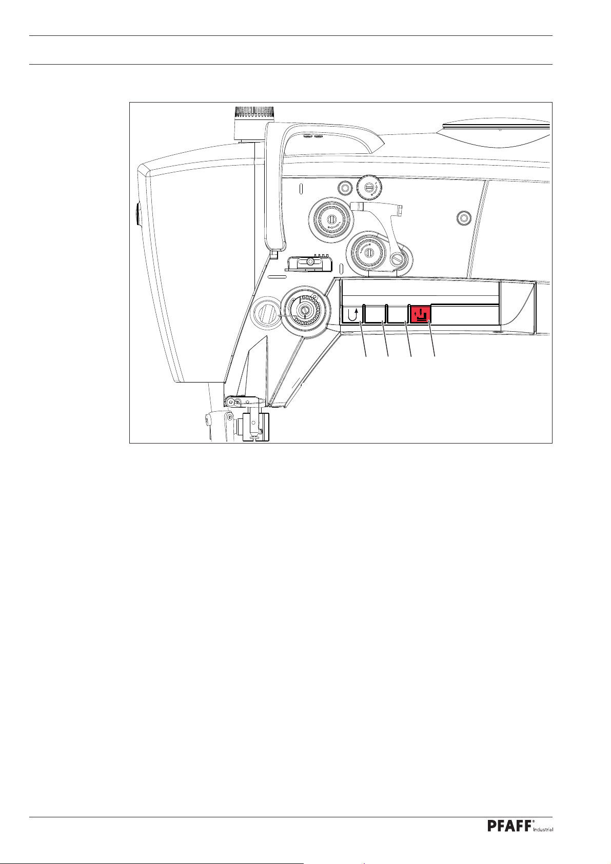
8.11 Inserting and removing the SD-memory card
Inserting the SD-memory card
● Open cover 1.
1
● Insert SD-memory card 2 into the card
slot with the label at the front.
● Close cover 1 again.
2
2 GB
max.
Removing the SD-memory card
● Open cover 1.
● Press the edge of the SD-memory card 2
lightly – the SD-card is ejected.
● Close cover 1 again.
Use only memory cards
formatted FAT 16
3
Fig. 8 - 10
By moving slide 3 it is possible to activate (position "LOCK") or deactivate
the write protection function of the SD-memory card. To store, process or
delete data on the SD-memory card, the write protection function must be
deactivated.
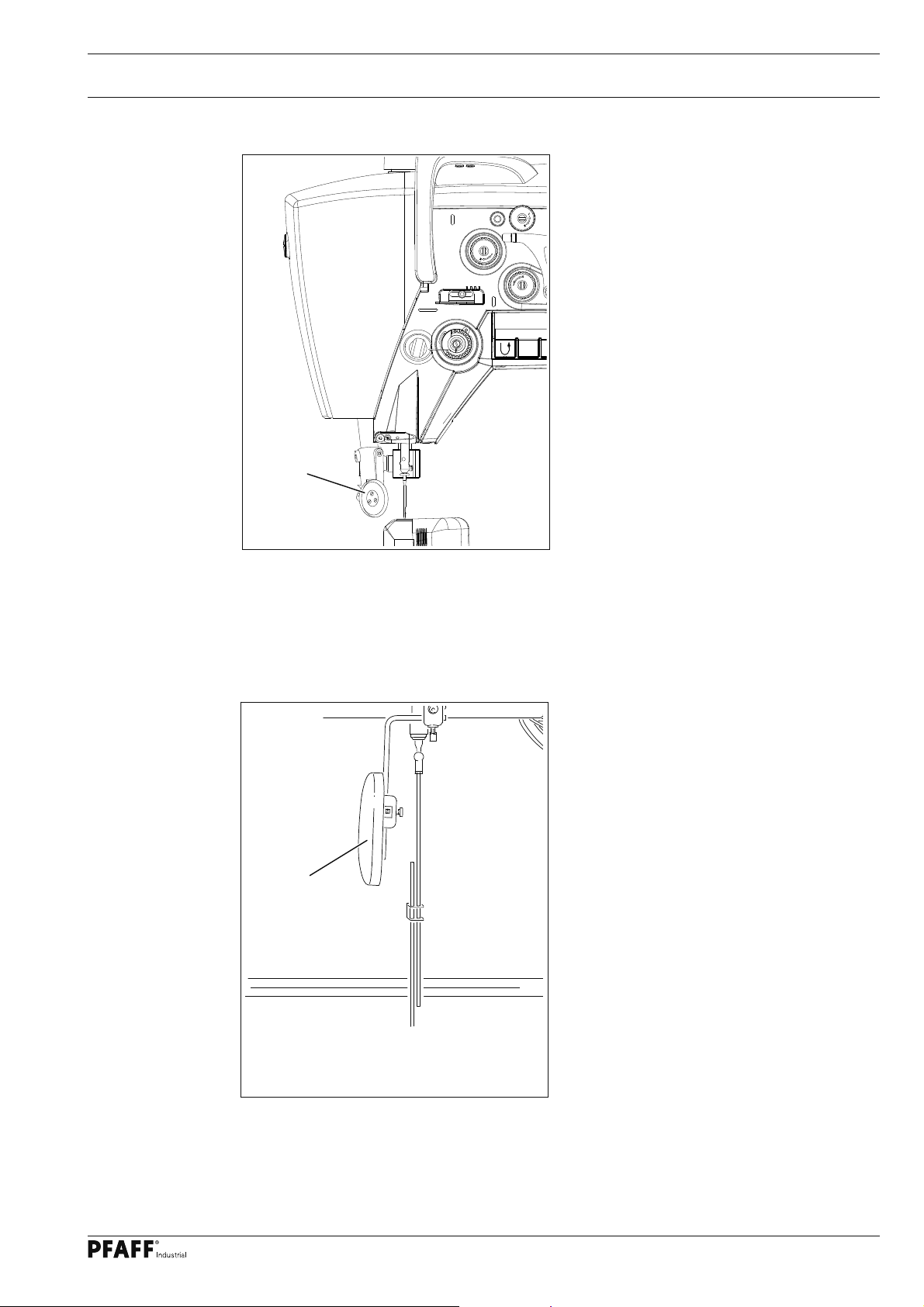
8.12 Upgrading from Version ME PLUS to Version ME PREMIUM
● Switch machine off.
PicoTop
BDF S3
Fig. 8 - 11
● Remove the PicoTop control panel.
● Attach the BDF S3 control panel to the
present carrier and connect the plug connection from the machine.
● Insert the SD card included, which has
the serial number of the machine labelled, as described in chapter 8.11 .
● Switch machine on.
● The machine will perform a boot process.
● Afterwards the BDF S3 control panel can
be used, as described in this instruction
manual.
● Remove the SD card included again from
the machine. It is read-only and is not intended to save programs.
Keep the SD card save for
further boot operations.
36
Page 37

Sewing
9.01.03 Selecting parameter entry
● Call up the parameter display (press the button several times if necessary).
● Switch on "TE / Input" (LED lights up).
104 1
The display will show the fi rst parameter with the corresponding setting value.
Parameters can be selected and values changed as follows:
Select the parameter
hundred digit (A+)
Select the parameter
hundred digit (A-)
Select the parameter ten and
single digit (B+)
● Selecting parameters and changing values, see chapter 9.03 Parameter Entry.
9.01.04 Selecting the maximum speed
● Call up the speed display (press the button several times if necessary).
● Switch on "TE / Input" (LED lights up).
Select the parameter ten and
single digit (B-)
Decrease the
parameter value (D+)
Decrease the
parameter value (D-)
3500
If the machine is in standstill the maximum speed will be displayed and can be
changed in hundred increments with the function key.
37
Page 38

Sewing
9.02 Programmed Sewing
● Switch machine on.
● Press the "PM" button to select programmed sewing (button LED is on)
● Where necessary enter the code and confi rm with the select button.
Before programmed sewing, programs must be set up
(see chapter 10.01 Programming Sewing).
Select sewing program number (A), seam section number (B)
and display seam section stitches
1 1 10
Display seam section speed limit (if activated)
1 1 n: 20
Start and end backtack stitch display
3 3 3 3
Sewing program number, seam section and special function display
38
1 1 I00
Page 39

Sewing
9.03 Error Messages
When a fault occurs the display shows "E" together with an error code, as shown in the fol-
lowing example. An error message can be caused by incorrect set up, faulty elements or
overloading.
E5
● Correct the fault.
● If necessary cancel fault correction.
For a description of errors see Chapter 1.08 in the Settings Manual, Error
Codes and Description.
39
Page 40

Input
10 Input
10
.01 Programming sewing
The displays given below are examples of the corresponding input options.
The input values displayed on the machine may differ.
● Switch machine on
● Call up the parameter display (press the button several times if necessary).
● Switch on "TE / Input" (LED lights up)
● Press the "PM" button to select programmed sewing (button LED is on)
● Where necessary enter the code and confi rm with the select button.
1
● Select program number (1 - 9).
● Press button D+ to accept the program number.
1 1 10
● The display will show program number (A) and seam section (B).
● Enter number of stitches (D) - if the display shows - - - the stitch count is inactive.
40
Page 41

Input
● If the "TE / Input" key is turned off, sewing functions for programmed sewing
can be turned on or off. If the function is turned on, the corresponding button
LED lights up:
Start backtack on/off
End backtack on/off
Raise needle position on/off Light barrier on/off
Thread trimming on/off Function on/off
● To enter more program functions turn the "TE/Input" button back on
(LED lights up)
● Press the select button until the display shows seam section backtack stitch input
(backtacks that are not possible are not stitched).
Raise foot position after sewing stop
on/off
Raise foot position at end of seam sec-
tion on/off
3 3 3 3
The display will show the backtack stitch numbers, which can be changed as follows:
Increase number of start
backtack forward stitches (A+). Value "0" = simpler
start backtack
Decrease number of start
backtack forward stitches
(A-).
Increase number of start
backtack backward stitches (B+).
Decrease number of start
backtack backward stitches (B-).
Decrease number of end backtack
backwards stitches (C+)
Decrease number of end backtack
backward stitches (C-)
Decrease number of end backtack
forward stitches (D+)
Value "0" = simpler end backtack
Decrease number of end backtack
forward stitches (D-)
41
Page 42

Input
● Press the select button until the display shows seam section maximum
speed input.
1 1 n: 20
● Enter the maximum speed for this seam section. (Display x100)
● Press the select button until the display shows seam section special
function input.
1 1 0I00
● Allocate the desired special functions (see following table) for the selected seam section
with the following function keys (Setting range C + D).
● If the program that is to be created has several seam sections, the value for setting range
"C" needs to be set to "0".
● To end the program the value for the setting range "C" needs to be set to "I" for the last
seam section.
Position in display Button Function
1. Position
2. Position
3. Position
I - Program fi nishes with the current seam section
0 - further seam sections follow
I - Turn on automatic stop at the end of seam section
0 - Turn off automatic stop at the end of seam section
I - Seam section is stitched backwards
0 - Seam section is stitched forwards
42
4. Position
● Press the "PM" button to quit program input.
● Press the select button to close entry mode.
I - Reverse end of seam section with pedal
0 - End of seam section without pedal
Page 43

Input
10.02 List of parameters for control P320 / P321
The operator has free access to the "100" parameters.
Parameters "200" - "800" can only be changed after entering a code number
and many only be changed by authorised personnel.
Group
1
Parameter
101 Pedal controlled start backtack
102 Reverse rotation (I = OFF, II = ON) I - II I
103 Placed stitch (I = OFF, II = ON) I - II I
104 Bobbin thread monitoring
105 Bobbin thread counter (2500 ME PREMIUM only) 0 - 99999 12000
106 Bobbin thread remaining counter
107 Stitch length adjustment (2500 ME PLUS only) -0,2 - +0,2 mm 0
108 Display main processer software version
109 Display step motor processor software version
110 Display control panel software version
111 Display sewing drive component software
Description
(I = OFF, II = ON)
(0 = Off, 1 = Counter)
(2500 ME PREMIUM only)
version
Setting range
I - II I
0 - 1 1
0 - 999 100
Set value
112 Control panel key tone (2500 PREMIUM only),
(I = OFF, II = ON)
113 Control panel key tone when moving from
one area to another (2500 PREMIUM only),
(I = OFF, II = ON)
116 Display serial number of machine - -
2
201 Machine confi guration
8 = 2571, 2591,
9 = 2571, 2591 with photo cell,
10 = reserved,
11 = reserved,
12 = 2574
13 = 2574 with photo cell
I - II II
I - II I
8 - 14 8
43
Page 44

Input
Group
2
Parameter
202 Roller-presser fi eld discharge (OFF = I, ON = II)
203 Single stitch button assignment
204 Half stitch button assignment
205 Button F1 assignment (2500 ME only)
206 Open thread tension on stop and lift roller-
Description
I = roller-presser is lowered slowly.
Should be set for high foot pressure
II = roller-presser is lowered quickly.
Should be set for low foot pressure
1 = Single stitch, 2 = Needle up,
3 = Knee switch
1 = Half stitch, 2 = Needle up,
3 = Knee switch
(I = Backtack suppression, II = Raise needle)
presser
(I = OFF, II = ON)
Setting range
I - II I
1 - 3 1
1 - 3 1
I - II I
I - II I
Set value
207 Open thread tension after trimming and
lift roller-presser
(I = OFF, II = ON)
3
301 Thread carrier position t.d.c.
2571, 2591 0 - 127 124
2574 0 - 191 1
302 Needle position under b.d.c.
2571, 2591 0 - 127 16
2574 0 - 191
303 Thread trimmer magnet position on
2571, 2591 0 - 127 16
2574 0 - 191 30
304 Thread trimmer magnet position pulse
2571, 2591 0 - 127 93
I - II I
30
44
2574 0 - 191 83
Page 45

Input
Group
3
4
Parameter
305 Thread trimmer magnet position off
306 Reverse rotation position
307 Placed stitch position
308 Thread tension ventilation position
401 Time delay roller-presser lift 0,01s - 1,5s 0,02s
Description
2571, 2591 0 - 127 113
2574 0 - 191 173
2571, 2591 0 - 127 93
2574 0 - 191 173
2571, 2591 0 - 127 7
2574 0 - 191 7
2571, 2591 0 - 127 30
2574 0 - 191 160
Setting range
Set value
402 Delayed start after lowering roller-presser 0,01s - 1,5s 0,15s
403 Set roller-presser lift
(must be increased for high foot pressure)
404 Thread trimmer magnet pulse 10 -50% 35%
5
501 Maximum speed
2571, 2591 100 - 3500 3500
2574 100 - 2600 2600
502 Start backtack speed 100 - 1500 700
503 End backtack speed 100 - 1500 700
504 Soft start speed 100 - 3500 1500
505 Soft start stitch 0 - 15 0
6
601 Move roller-presser and feed wheel step motor
0,01s - 0,2s 0,03s
45
Page 46

Input
Group
600 602
Parameter
Description
Inputs: 0123456789ABCDEF
(2571, 2574, 2591 PREMIUM only),
0 = Needle mid point (E16)
1 = Needle mid point (E15)
2 = Intermittent coding (E14)
3 = Free (E13)
4 = Free (E12)
5 = Free (E11)
6 = Free (E10)
7 = Free (E9)
8 = Emergency button (E8)
9 = Free (E7)
A = Knee switch (E6)
B = Photo cell (E5)
C = Starting inhibitor (E4)
D = Single stitch button on
machine head (E3)
E = Half stitch button on
machine head (E2)
F = Reverse button on
machine head (E1)
Setting range
Set value
603 Machine drive in home position see
set-up-instructions
604 Run cold start
605 Stitch process with step motors by handwheel
606 Display speed control unit value
7
701 P-section speed regulator
2571, 2591 1 - 50 30
2574 1 - 50 20
702 I-section speed regulator 0 - 100 50
703 P-section position regulator 1 - 50 20
704 D-section position regulator 1 - 100 30
705 Time for position regulator 0 - 100 25
706 P-section position regulator for remainder brake 1 - 50 25
707 D-section position regulator for remainder brake 1 - 50 15
708 Maximum torque for remainder brake 0 - 100 0
0 - 127 8 ± 2
46
709 Minimum machine speed 3 - 64 6
Page 47

Input
700
Group
Parameter
710 Maximum machine speed
711 Maximum motor speed
712 Positioning speed 3 - 25 18
713 Acceleration ramp 1 - 50 35
714 Braking ramp 1 - 50 30
715 Reference position
716 Dead man time 0 - 255 40
717 Motor starting current 3 -10 8
Description
2571, 2591 1 - 35 35
2574 1 - 26 26
2571, 2591 1 - 35 35
2574 1 - 40 40
2571, 2591 0 - 127 10
2574 0 - 191 35
Setting range
Set value
800
718 Vibration fi lter 1 -10 6
719 Assign direction of rotation 0 - 1 0
720 Move positioner 1 - 2 2
801 Function group 100 access authorisation
(Operator level)
802 Function group 200 access authorisation
(Technician level)
803 Function group 300 access authorisation
(Sewing motor positions)
804 Function group 400 access authorisation (Times) 0 - 1 1
805 Function group 500 access authorisation
(Counter and revolution speed)
806 Function group 600 access authorisation
(Service)
807 Function group 700 access authorisation
(Sewing motor)
808 Function group 800 access authorisation
(Access authorisation)
0 - 1 0
0 - 1 1
0 - 1 1
0 - 1 1
0 - 1 1
0 - 1 1
0 - 1 1
809 Programming access authorisation 0 - 1 1
810 Input access code 0 - 9999 2500
47
Page 48

Input
10.03 Error Messages and Description
Error Description
E 1 System error
E 2 Sewing motor E002/BB/xxx
BB = 20: Deadman
02: Position forwards
03: Position in reverse
05: Position by shortest route
09: Write parameter
10: Speed
0A: Reset stitch counter
0B: Stop after xxx stitches
30: Timeout for increasing speed
31: Timeout from uncertain positioning
32: Timeout from deadman command
33: Timeout for deleting errors
34: Timeout for emergency stop
35: Timeout for writing parameters
36: Timeout for resetting stitch counter
37: Timeout for stop command after x stitches
38: Timeout for initialisation
39: Establishing contact when turned on
xxx = sewing motor control unit error byte (see Motor Errors)
E 3 Section
E 4 End of section
E 5 Pedal or half stitch button or single stitch button (on machine head)
activated when machine turned on
E 6 Communication error with the step motor processor
E 7 End of ramp
E 8 Needle drive end point not found
E 9 Needle drive mid-point not found
E 10 Step motor processor error
E 11 Step motor step frequency too high
E 12 Sewing displacement error
E 13 Docu-seam system error
E 14 Incorrect program number (larger than 99)
E 15 Incorrect section number
E 16 Memory full
E 17 Incorrect stitch length
E 18 Unused
E 19 External control interface
E 20 Incorrect control
E 21 Power supply unit overloaded (24V)
E 22 Mains voltage
E 23 Power supply 24V too low
48
Page 49

Input
10.04 Motor Errors
Error Description
33 Invalid parameter value
35 Communication error
36 Init not ready
37 Command overrun
64 Mains off during initialisation
65 Excess current directly after mains on
66 Short circuit
68 Excess current during operation
70 Motor blocked
71 No incremental plug
74 Incremental transducer missing for transmission/reduction
173 Motor blocked in 1st stitch
175 Interior starting error
222 Dead man monitoring
49
Page 50

Care and maintenance
11 Care and maintenance
11
.01 Servicing and maintenance intervals
Cleaning the machine ...................................................... Daily, before starting the machine
Clean the hook compartment ...............................Daily, several times if in continuous use
Check the oil level ........................................................... Daily, before starting the machine
Greasing the bevel gears ....................................................................................once a year
Clean the blower air fi lter ................................................................................... as required
These maintenance intervals are calculated for the average running time of a
single shift operation. If the machine is operated more than this, shorter inter-
vals are recommended.
11 .02 Cleaning the machine
The cleaning cycle required for the machine depends on following factors:
● Single or several shift operation
● Amount of dust resulting from the workpiece
It is therefore only possible to stipulate the best possible cleaning instructions for each individual case.
Fig. 11 - 01
For all cleaning work the machine must be disconnected from the mains
by switching off the on/off switch or by removing the mains plug!
Danger of injury if the machine suddenly starts up .
● Bring the needle bar to its highest position.
5 mm
2
● Open the post cap and remove the bob-
bin case cap and the bobbin.
● Unscrew hook gib 1.
● Turn the handwheel until the point of
bobbin case 2 penetrates into the groove
of the hook race approx. 5 mm.
1
● Remove bobbin case 2.
● Clean the hook race with paraffi n.
● When inserting the bobbin case 2, ensu-
re that the horn of the bobbin
● case 2 engages in the groove of the
needle plate.
3
● Screw hook gib 1 back on and close the
post cap.
Do not operate machine while
post cap is open!
Risk of injury from rotating
clamp!
50
Page 51

Care and maintenance
11 .03 Oiling the hook
Switch the machine off!
Danger of injury if the machine
is started accidentally!
● Before commissioning the machine, and
after long periods out of operation, pour
a few drops of oil into the hook race (see
arrow).
Only use oil with a mean viscosity of 22.0 mm²/s at 40ºC
and a density of 0.865 g/cm³ at
15ºC.
We recommend
PFAFF sewing machine oil,
Fig. 11 - 03
part number 280-1-120 144.
11 .04 Monitoring the oil level for clamp and head pieces
● Before commissioning the machine,
fi ll in oil through hole 1 until the oil level
indicator 2 is at the "MAX" marking.
● Check the oil level daily before starting
the machine!
The level of the oil in indicator 2
must not sink below the "MIN"
marking and not exceed the
Max
Min
2
● If required, fi ll oil into the tank through
hole 1.
"MAX" marking.
1
Fig. 11 - 04
Only use oil with a mean viscosity of 22.0 mm²/s at 40ºC and a density of
0.865 g/cm³ at 15ºC.
We recommend PFAFF sewing machine oil, part number 280-1-120 144.
51
Page 52

Care and maintenance
11 .05 Lubricating the bevel gears
1
Fig. 11 - 05
Switch the machine off!
Danger of injury if the machine
is started accidentally!
● All bevel gears must be supplied with
new grease once a year.
● Tilt the sewing head back onto the sup-
port.
● To set the sewing head upright, press
tilt lock 1 backwards and set the sewing
head upright using both hands.
Use both hands to set the sew-
ing head upright!
Danger of crushing between
the sewing head and the table
top!
We recommend PFAFF sodium grease with a dripping point of approx. 150C,
Order No. 280-1-120 243.
11
.06 Cleaning the blower air fi lter
● Remove cover 1.
● Take out fi lter element and clean with
compressed air.
● Insert the clean fi lter element and
replace cover 1.
1
52
Fig. 11 - 06
Page 53

Wearing parts
12 Wearing parts
This is a list of the most important wearing parts.
A detailed parts list for the complete machine is included with the accessori-
es. In case of loss, the parts list can be downloaded from the internet address
www.pfaff-industrial.com/pfaff/de/service/downloads As an alternative to
the internet download the parts lists can also be ordered in book form under
part no. 296-12-19 128.
91-164 697-93/001
(Roller presser, with 30 mm dia., 4.0 mm wide, toothed)
12-305 174-15
11-130 284-15
11-130 284-15
91-263 430-91
91-263 435-91
A B
C
91-263 392-91
91-000 390-05
91-000 928-15
91-010 166-05
91-175 690-05
91-263 397-01
91-000 529-15 (3x)
91-263 428-05
91-263 291-05
91-018 293-05
11-108 093-25
11-174 082-15
System 134 (2571 + 2591)
System 134-35 (2574)
A B
C
11-330 085-15
91-140 945-05
91-263 427-05
91-118 308-05
91-000 452-15 (2x)
53
Page 54

Wearing parts
91-500 460-05
99-137 520-05
91-500 251-05
11-130 092-15 (2x)
91-263 139-05
2571-725/04
Sub-class -900/81
91-263 294-05
12-315 080-15 (2x)
11-108 846-15 (2x)
11-108 093-15 (2x)
91-263 348-05
2591-725/04
11-130 167-15
11-173 168-15
54
91-119 202-04/001
91-011 165-04/001
Page 55

Note
Page 56

PFAFF Industriesysteme
und Maschinen AG
Hans-Geiger-Str. 12 - IG Nord
D-67661 Kaiserslautern
Telefon: +49 - 6301 3205 - 0
Telefax: +49 - 6301 3205 - 1386
E-mail: info@pfaff-industrial.com
Gedruckt in der BRD / Printed in Germany / Imprimé en la R.F.A. / Impreso en la R.F.A
© PFAFF Industriesysteme und Maschinen AG 2009, PFAFF is the exclusive trademark of VSM Group AB.PFAFF Industriesysteme und Maschinen AG is an authorized licensee of the PFAFF trademark.
 Loading...