

Page 1

2545
2546
INSTRUCTION MANUAL
This instruction manual applies to machines from the
following serial numbers onwards:
# 2 798 767
296-12-19 219/002
Betriebsanleitung engl. 09.12
Page 2

This Instruction Manual is valid for all models and subclasses listed in the
chapter "Specifi cations".
The adjustment manual for the machines can be downloaded free of
charge from the internet address
www.pfaff-industrial.com/pfaff/de/service/downloads.
As an alternative to the internet download the adjustment manual can also be
ordered in book form under part no.296-12-19 220/002.
The reprinting, copying or translation of PFAFF Instruction Manuals, whether in whole or
in part, is only permitted with our previous authorization and with written reference to the
source.
PFAFF Industriesysteme
und Maschinen AG
Hans-Geiger-Str. 12 - IG Nord
D-67661 Kaiserslautern
Page 3

Index
Contents ..................................................................................Page
1 Safety .................................................................................................................................... 5
1.01 Directives ...............................................................................................................................5
1.02 General notes on safety ......................................................................................................... 5
1.03 Safety symbols ......................................................................................................................6
1.04 Important points for the user ................................................................................................. 6
1.05 Operating and specialist personnel ........................................................................................ 7
1.05.01 Operating personnel .............................................................................................................. 7
1.05.02 Specialist personnel ............................................................................................................... 7
1.06 Danger warnings .................................................................................................................... 8
2 Proper use............................................................................................................................. 9
3 Specifi cations ..................................................................................................................... 10
3.01 PFAFF 2545 / 2546 (BASIC, CLASSIC and PLUS) ............................................................... 10
3.02 Maximum speed ................................................................................................................. 11
3.03 Machine equipment and options ......................................................................................... 12
4 Disposal of Machine .......................................................................................................... 13
5 Transportation, packing and storage ................................................................................ 14
5.01 Transportation to customer‘s premises ............................................................................... 14
5.02 Transportation inside the customer‘s premises ................................................................... 14
5.03 Disposal of packing materials ..............................................................................................14
5.04 Storage ................................................................................................................................ 14
6 Explanation of symbols ..................................................................................................... 15
7 Controls .............................................................................................................................. 16
7.01 On/off switch ...................................................................................................................... 16
7.02 Sewing lamp switch (only on the PFAFF 2545 / 2546 CLASSIC and PLUS) ........................ 16
7.03 Pedal .................................................................................................................................... 17
7.04 Keyboard on machine head (only on the PFAFF 2545 / 2546 CLASSIC and PLUS) .............18
7.05 Knee switch (option) ............................................................................................................21
7.06 Knee lever (only on the PFAFF 2545 / 2546 BASIC) ............................................................. 21
7.07 Lever for lifting the presser foot ........................................................................................... 22
7.08 Adjusting the stitch length (on the PFAFF 2545 / 2546 BASIC and CLASSIC) ..................... 22
7.09 Adjusting the stitch length (on the PFAFF 2545 / 2546 PLUS) ............................................. 23
7.10 Reverse feed lever ............................................................................................................... 23
7.11 Adjusting the top feed stroke (on the PFAFF 2545 / 2546 BASIC and CLASSIC) ................. 24
7.12 Adjusting the top feed stroke (on the PFAFF 2545 / 2546 PLUS) ........................................ 24
Page 4

Index
Contents ..................................................................................Page
7.13 Switchable needle thread tension (only on the PFAFF 2545 / 2546 BASIC ) .......................25
7.14 Bobbin thread monitor with remaining thread recognition by sensor (sub-class -926/06)
Bobbin thread control by reverse stitch counting (with P74 ED-L + PF 321) ....................... 25
7.15 Bobbin thread control by stitch-counting (with PicoDrive) ...................................................26
7.16 Control panel ........................................................................................................................26
8 Preparation ........................................................................................................................ 27
8.01 Inserting the needle ............................................................................................................. 27
8.02 Winding the bobbin thread, regulating the winder tension .................................................. 28
8.03 Bobbin-changing/threading, and regulating the bobbin thread tension ................................ 29
8.04 Setting the bobbin thread control function by reverse stitch counting .....................................29
8.04 .01 Machines with P45 PD2-L and P74 ED-L ..................................................................................29
8.04 .02 Machines with PF 321 ..............................................................................................................29
8.05 Setting the bobbin thread monitor with remaining thread recognition by sensor
(sub-class -926/06) ............................................................................................................... 30
8.05 .01 Machines with P74 ED-L ...................................................................................................... 30
8.05 .02 Machines with P74 ED-L ...........................................................................................................30
8.06 Threading needle thread and regulating its tension on the 2545 ............................................31
8.07 Threading needle thread and regulating its tension on the 2546 ............................................32
9 Care and maintenance ....................................................................................................... 33
9.01 Servicing and maintenance intervals ................................................................................... 33
9.02 Cleaning the machine .......................................................................................................... 33
9.03 Lubricating ........................................................................................................................... 34
9.04 Checking/regulating the air pressure ................................................................................... 35
9.05 Emptying/cleaning the water bowl of the air fi lter/regulator ................................................ 35
10 Wearing parts ..................................................................................................................... 36
Page 5

Safety
1 Safety
1
.01 Directives
This machine is constructed in accordance with the European regulations contained in the
conformity and manufacturer’s declarations.
In addition to this Instruction Manual, also observe all generally accepted, statutory and
other regulations and legal requirements and all valid environmental protection regulations!
The regionally valid regulations of the social insurance society for occupational accidents or
other supervisory organizations are to be strictly adhered to!
1.02 General notes on safety
● This machine may only be operated by adequately trained operators and only after having
completely read and understood the Instruction Manual!
● All Notes on Safety and Instruction Manuals of the motor manufacturer are to be read be-
fore operating the machine!
● The danger and safety instructions on the machine itself are to be followed!
● This machine may only be used for the purpose for which it is intended and may not be
operated without its safety devices. All safety regulations relevant to its operation are to
be adhered to.
● When exchanging sewing tools (e.g. needle, roller presser, needle plate and bobbin),
when threading the machine, when leaving the machine unattended and during mainte-
nance work, the machine is to be separated from the power supply by switching off the
On/Off switch or by removing the plug from the mains!
● Everyday maintenance work is only to be carried out by appropriately trained personnel!
● Repairs and special maintenance work may only be carried out by qualifi ed service staff
or appropriately trained personnel!
● Work on electrical equipment may only be carried out by appropriately trained personnel!
● Work is not permitted on parts and equipment which are connected to the power supply!
The only exceptions to this rule are found in the regulations EN 50110.
● Modifi cations and alterations to the machine may only be carried out under observance
of all the relevant safety regulations!
● Only spare parts which have been approved by us are to be used for repairs! We express-
ly point out that any replacement parts or accessories which are not supplied by us have
not been tested and approved by us. The installation and/or use of any such products can
lead to negative changes in the structural characteristics of the machine. We are not liable
for any damage which may be caused by non-original parts.
5
Page 6
Safety
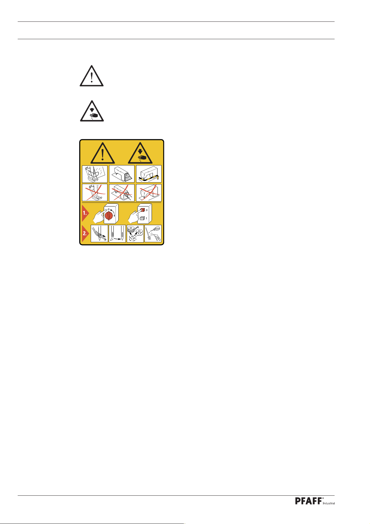
1.03 Safety symbols
Danger!
Points to be observed..
Danger of injury for operating and specialist personnel!
Caution
Do not operate without fi nger guard and safety devices.
Before threading, changing bobbin and needle, cleaning
etc. switch off main switch.
I
1.04 Important points for the user
● This Instruction Manual is an integral part of the machine and must be available to the
operating personnel at all times.
● The Instruction Manual must be read before operating the machine for the fi rst time.
● The operating and specialist personnel is to be instructed as to the safety equipment of
the machine and regarding safe work methods.
● It is the duty of the user to only operate the machine in perfect running order.
● It is the obligation of the user to ensure that none of the safety mechanisms are removed
or deactivated.
● It is the obligation of the user to ensure that only authorized persons operate and work
on the machine.
Further information can be obtained from your PFAFF agent.
6
Page 7

Safety
1.05 Operating and specialist personnel
1
.05.01 Operating personnel
Operating personnel are persons responsible for the equipping, operating and cleaning of
the machine as well as for taking care of problems arising in the sewing area.
The operating personnel is required to observe the following points and must:
● always observe the Notes on Safety in the Instruction Manual!
● never use any working methods which could adversely affect the safety of the machine!
● not wear loose-fi tting clothing or jewelery such as chains or rings!
● also ensure that only authorized persons have access to the potentially dangerous area
around the machine!
● always immediately report to the person responsible any changes in the machine which
may limit its safety!
1.05.02 Specialist personnel
Specialist personnel are persons with a specialist education in the fi elds of electrics, electro-
nics and mechanics. They are responsible for the lubrication, maintenance, repair and adjust-
ment of the machine.
The specialist personnel is obliged to observe the following points and must:
● always observe the Notes on Safety in the Instruction Manual!
● switch off the On/Off switch before carrying out adjustments or repairs, and ensure that
it cannot be switched on again unintentionally!
● wait until the luminous diode on the control box is no longer blinking or on before begin-
ning adjustment or repair work.
● never work on parts which are still connected to the power supply! Exceptions are explai-
ned in the regulations EN 50110.
● replace the protective coverings and close the electrical control box afer all repairs or
maintenance work!
7
Page 8
Safety
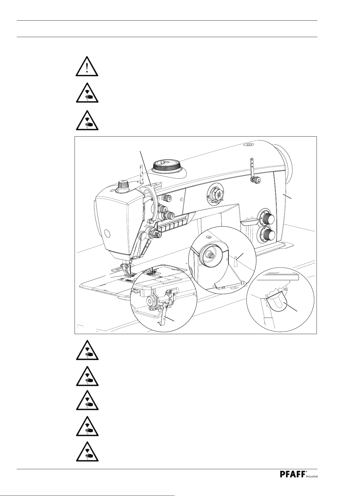
1.06 Danger warnings
A working area of 1 m must be kept free both in front of and behind the machi-
ne, so that easy access is possible at all times.
Never put your hands or fi ngers in the sewing area during sewing!
Danger of injury by the needle!
While setting or adjusting the machine do not leave any objects on the table nor
in the needle plate area! Objects may be trapped or fl ung out of the machine!
2
3
Fig. 1 - 01
6
1
4
5
Do not run the machine without fi nger guard 1!
Danger of injury by up and down movement of needle!
Do not run the machine without take-up lever guard 2!
Danger of injury by moving take-up lever!
Do not run the machine without belt guards 3 and 4!
Danger of injury by rotating v-belt!
Do not operate the machine without tilt lock 5!
Danger of crushing between sewing head and table!
Do not operate the machine without support 6! Danger due to top-heavy
sewing head! Machine can tip over backwards when tilted!
8
Page 9
Proper use
2 Proper use
The PFAFF 2545 BASIC, CLASSIC and PLUS are special high-speed, single needle lock-
stitch sewing machines with unison feed and a large, respectively extra large hook.
The PFAFF 2546 BASIC, CLASSIC and PLUS are special high-speed, two needle lockstitch
sewing machines with unison feed and a large, respectively extra large hook.
The machines are used for sewing lockstitch seams in the textile industry.
Any and all uses of this machine which have not been approved of by the
manufacturer are considered to be inappropriate! The manufacturer cannot be
held liable for any damage caused by the inappropriate use of the machine!
The appropriate use of the machine includes the observance of all operational,
adjustment, maintenance and repair measures required by the manufacturer!
9
Page 10

Specifi cations
3 Specifi cations
.01 PFAFF 2545 / 2546 (BASIC, CLASSIC and PLUS)
3
Stitch type: .........................................................................................................301 (lockstitch)
Needle system: .............................................................................................................. 134-35
Version CN; CN9; CN12: ............................................. for processing medium-heavy materials
Version DN; DN12: .................................................................... for processing heavy materials
Needle size in 1/100 mm:
Version CN9: .............................................................................................................. 110 – 140
Version DN12: ........................................................................................................... 150 – 200
Max. stitch length:
Version CN; DN: ...............................................................................................................6 mm
Version CN9: ....................................................................................................................9 mm
Version CN12; DN12: .....................................................................................................12 mm
Max.thread size (synthetic):
Version CN.. : .................................................................................................................. 15/3
Version DN.. : .................................................................................................................... 8/3
❋
▲
▲
Presser foot clearance: ..................................................................................................20 mm
Clearance width: ..........................................................................................................350 mm
Clearance height: .........................................................................................................120 mm
Bed plate dimensions: .......................................................................................640 x 200 mm
Noise data:
Noise emission level at workplace with a sewing speed of 2400 spm: ............ LpA < 80 dB(A)
(Noise measurement in accordance with DIN 45 635-48-A-1, ISO 11204, ISO 3744, ISO
Motor data: .................................................................... See instruction manual for the motor
Leakage current ........................................................................................................... < 5 mA
Air consumption per switch cycle: ...............................................................................0.146 NI
Net weight of sewing head: .................................................................................approx. 72 kg
Gross weight of sewing head : .............................................................................approx. 82 kg
❋
Subject to alterations
◆
Due to the use of network fi lters there is a nominal leakage current of < 5 mA.
▲
synthetic, or other sizes of comparable thread types
■
KpA = 2,5 dB
■
◆
10
Page 11
Specifi cations
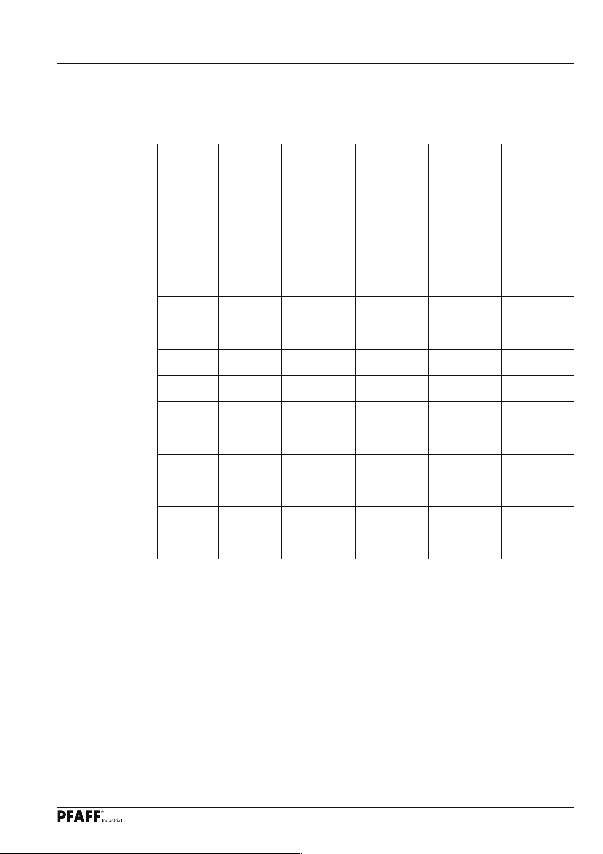
3.02 Maximum speed
Top feed lift
1 - 2 mm up to 9 mm
2,5 - 4 mm up to 9 mm
4,5 - 5 mm up to 9 mm
Stitch length range
Max. speed / spm
3800
3200
2600
on version C and with
large hook
◆
◆
◆
Max. speed / spm on
version C and with
3400
2800
2200
extra-large hook
◆
◆
◆
Max. speed / spm
3000
2800
2400
on version D and with
large hook Max. speed / spm on
◆
◆
◆
version D and with
2700
2700
2200
5,5 - 7 mm up to 9 mm 2000 1800 1800 1800
7,5 - 9 mm up to 9 mm 1800 1800 1600 1600
1 - 2 mm 9,5 - 12 mm
2,5 - 4 mm 9,5 - 12 mm
4,5 - 5 mm 9,5 - 12 mm
2200
2200
2200
◆
◆
◆
2200
2200
2200
◆
◆
◆
2200
2200
2200
◆
◆
◆
2200
2200
2200
5,5 - 7 mm 9,5 - 12 mm 2000 1800 2000 1800
7,5 - 9 mm 9,5 - 12 mm 1800 1800 180 0 1800
◆
The max. speed on the PFAFF 2546 with needle gauge larger than 20 mm is 2000 spm.
extra-large hook
◆
◆
◆
◆
◆
◆
11
Page 12
Specifi cations
3.03 Machine equipment and options
PFAFF 2545 / 2546
Vetical hook, large
Vetical hook, extra large
Thread trimmer (-900/81), < 13 mm rest thread
Thread trimmer (-900/82), < 5 mm rest thread
Thread puller (-909/12), controlled
Presser foot lift, manual via knee lever
Presser foot lift (-910/04), electropneumatic
Manual backtacking with mech. hand switch
Automatic backtacking (-911/35), electropneumatic
1 preselectable stitch length
2 preselectable stitch lengths, can be switched alternately
2 preselectable thread tensions, one can be switched on manually
2 preselectable thread tensions, one can be switched on electropneumatically by hand switch
1 presser foot stroke, manually adjustable, top feed stroke up to max. 9 mm
2 presser foot strokes, manually adjustable, preselectable quick stroke
adjustment with hand switch (electropneumatically controlled)
Drop feed, adjustable
Oil level control through inspection glass
Oil level on display, with warning light on machine head
Presser foot pressure, manually adjustable
Clutch motor
DC-motor functionality PicoDrive P45 PD-L
DC-motor functionality P74 ED-L, PF 321
Control panel - PicoTop
Remaining bobbin thread recognition function by stitch counting with
LED display
Bobbin thread monitor with remaining thread recognition by sensor
(sub-class -926/06
Integrated multiple switch on machine head + programmed multi switch
Integrated LED sewing lamp on sewing head, dimmable
Bobbin thread winding device
Attachment slider
Skip stitch detector SSD -
Bobbin thread monitoring with thread detection -
Safety coupling
BASIC
CLASSIC
PLUS
●●●
❍❍❍
-
●●
-
❍❍
-
❍❍
--
●
-
●●
●●●
-
●●
●●
--
●
-
●●
--
●●●
●●●
-
●●●
●
❍
-
-
-
--
-
❍●●
●●●
●●●
●●●
-
●
--
●●
-
●
●●
--
--
●●
●●
●●
❍
●●
❍❍
❍❍
12
● = standard, ❍ = optional
Page 13

Disposal of Machine
4 Disposal of Machine
● Proper disposal of the machine is the responsibility of the customer.
● The materials used for the machine are steel, aluminium, brass and various plastic
materials. The electrical equipment comprises plastic materials and copper.
● The machine is to be disposed of according to the locally valid pollution control regula-ti-
ons; if necessary, a specialist ist to be commissioned.
Care must be taken that parts soiled with lubricants are disposed of separately
according to the locally valid pollution control regulations!
13
Page 14

Transportation, packing and storage
5 Transportation, packing and storage
5
.01 Transportation to customer‘s premises
The machines are delivered completely packed.
5.02 Transportation inside the customer‘s premises
The manufacturer cannot be made liable for transportation inside the customer‘s premises
nor to other operating locations. It must be ensured that the machines are only transported
in an upright position.
5.03 Disposal of packing materials
The packing materials of this machine comprise paper, cardboard and VCE fi bre. Proper dis-
posal of the packing material is the responsibility of the customer.
5.04 Storage
If the machine is not in use, it can be stored as it is for a period of up to six months, but It
should be protected against dust and moisture.
If the machine is stored for longer periods, the individual parts, especially the surfaces of
moving parts, must be protected against corrosion, e.g. by a fi lm of oil.
14
Page 15

Explanation of symbols
6 Explanation of symbols
In this instruction manual, work to be carried out or important information is accentuated by
symbols. These symbols have the following meanings:
Note, information
Cleaning, care
Lubrication
Maintenance, repairs, adjustment, service work
(only to be carried out by technical staff)
15
Page 16

Controls
7 Controls
7
.01 On/off switch
2
1
Fig. 7 - 01
Machines with motor P45 PD2-L + P74 ED-L
● The power supply to the machine is swit-
ched on or off by turning switch 1.
Fig. 7 - 01a
Machines with motor PF 321
● Operate main switch 2 to switch the
machine on or off.
7.02 Sewing lamp switch (only on the PFAFF 2545 / 2546 CLASSIC and PLUS)
● Switch the sewing lamp, which is inte-
grated in the machine head, on or off by
operating switch 1.
1
16
Fig. 7 - 01b
Page 17

Controls
7.03 Pedal
● With the on/off switch on
0 +1
0 = Machine stop
+1 = Sew
- 1 = Raise presserfoot
- 2 = Trim thread (on machines with
thread trimmer)
-1 -2
Fig. 7 - 03
17
Page 18

Controls
7.04 Keyboard on machine head (only on the PFAFF 2545 / 2546 CLASSIC and PLUS)
2
3 4X5 6
X
7 8
B
A
Fig. 7 - 04
● The machine has a keyboard with 8 keys to activate different functions.
● In the keys 2 – 7 there are yellow LEDs. These shine when the respective function has
been allocated to key 1.
● Green LEDs are located above the keys 2 - 7. These shine when the function has been
activated.
● Above key 1 there are two symbol lamps.
Lamp A indicates the status of the bobbin thread control.
Lamp B shines when the minimum level of the oil supply has been reached.
● When the keys 1 – 8 are operated, the functions listed below are carried out.
Key 1: The functions of the keys 2 - 7 can be allocated to this key.
To program key 1, simultaneously press one of the keys 2 - 7 and key 1 for approx.
3 seconds. The function of the selected key is taken over and the yellow LED in this
key lights up
(For drive system P74 ED-L = standard)
For drive system PF 321, the value 94 is set under parameter 840 (= standard).
Key 2: Reverse sewing or intermediate backtacks during the seam.
(On drive system P74 ED-L under Parameter 634 other functions can be assigned to
this key: ON = Feed adjustment when machine has stopped and when machine is running
(standard)
OFF = Feed adjustment only when machine is running
For drive system PF 321, the value 16 is set under parameter 841 (= standard).
1
X
only on the version PLUS
18
Page 19

Controls
Key 3: Needle position change
This button can have the following functions assigned depending on the drive
system implemented and by way of changes to the parameter values:
P74 ED-L PF 321
Parameter Function Parameter Function
695
Key 4: Calling up the pre-selected top feed lift.
(Diode on = high lift, diode off = low lift)..
This button can have the following functions assigned depending on the drive
system implemented and by way of changes to the parameter values:
0 = Off
1 = needle raised without trimming
2 = needle position change (standard)
3 = single stitch
4 = single stitch in reverse
5 = moving forwards to needle
position step by step
6 = programmable tack on / off
842
0 = Function off
01 = Needle up without trimming
02 = Change needle position (standard)
03 = Single stitch
20 = Step-by-step approach to a
needle position forward
95 = Offset multi-backtack
96 = Backtack suppression (all autom.
backtack deactivated)
97 = Single stitch reverse
98 = Not used
P74 ED-L PF 321
Parameter Function Parameter Function
401
Key 5: Bartack suppression for one bartack.
This button can have the following functions assigned depending on the drive
system implemented and by way of changes to the parameter values:
Parameter Function Parameter Function
780
0 = Off
1 = when key pressed constant
second stroke (standard)
2 = second stroke only as long as key
pressed
If this key is operated, the second
voltage is switched on
This function can be switched off under Parameter 764
P74 ED-L PF 321
0 = Off
1 = tack inversion once (standard)
2 = tack suppression (all tacks
switched off)
3 = reverse move to needle position
step by step
4 = edge trimmer on / off
5 = programmable tack on / off
843
844
0 = Off
01 =
With button pressed constantly,
2nd lift (standard)
02 = 2nd lift only while button is
pressed
14 = Stroke adjustment (Flip Flop 1)
with speed limit N10
(Parameter 137 must be set to "On"
17 = Backtack inversion, single
(standard)
21 = Step-by-step approach to a
needle position reverse
95 = Offset multi-backtack
96 = Backtack suppression
(all autom. backtack deactivated)
97 = Single stitch reverse
98 = Not used
19
Page 20

Controls
Key 6: Calling up the pre-set stitch length
Diode on = large stitch length, diode off = small stitch length.
This button can have the following functions assigned depending on the drive
system implemented and by way of changes to the parameter values:
P74 ED-L PF 321
Parameter Funktion Parameter Funktion
786
Key 7: If this key is operated, the second thread tension is switched on.
If this key is pressed for longer than about 2 seconds, the machine moves to the
threading position - the needle is raised and the motor start inhibitor is activated
(sewing threads are not trimmed).
If the key is operated again, the motor start inhibitor is deactivated again
(For drive system P74 ED-L = standard)
For drive system PF 321, the value 93 is set under parameter 846 (= standard).
Function = Standard
This function can be switched off
under Parameter 786.
845
22 = Speed limitation n11 , Flip Flop 2
(Parameter 186 must be set to "On".
Key 8: EMERGENCY KEY
Needle is raised without trimming, the thread clamp is opened, the thread
tension is released, the presser foot raised and the motor start inhibitor activated.
Deactivation the motor safety lock
For drive system P74 ED-L - click the button 'Scroll'.
For drive system PF 321 - click the button 'E' (under parameter 847, the value 24 is
set = standard)
The method for setting parameters is described in the settings manual, and
may only be carried out by certifi ed professionals!
20
Page 21

Controls
7.05 Knee switch (option)
● Depending on how the machine is equip-
ped, the following functions can be called
up with the knee switch:
1. On machines with centre guide (sub-class
-63/24) this can be engaged or disen-
gaged by operating the knee switch.
2. By operating knee switch 1 it is possible
to alternate between two pre-selected
feed stroke settings.
For the high stroke setting the
speed is reduced.
1
The knee switch function can
be altered, see the instruction
manual for the control panel.
Fig. 7 - 05
7.06 Knee lever (only on the PFAFF 2545 / 2546 BASIC)
● By pressing the knee lever 1 in the
direction of the arrow, the presser foot is
raised.
Fig. 7 - 06
21
Page 22

Controls
7.07 Lever for lifting the presser foot
● The sewing foot can be lifted by raising
lever 1.
1
Fig. 7 - 07
7.08 Adjusting the stitch length (on the PFAFF 2545 / 2546 BASIC and CLASSIC)
● Adjustment wheel 1 is used to pre-select
the stitch length
22
1
Fig. 7 - 08
Page 23

Controls
7.09 Adjusting the stitch length (on the PFAFF 2545 / 2546 PLUS)
● Two different stitch lengths can be pre-
selected on the thumbs wheels 1 and 2.
● The adjustment can be made by turning
the thumb wheels.
● The larger stitch length is set on thumb
wheel 1, and the smaller stitch length on
thumb wheel 2.
● Use key 4 to call up the pre-selected
stitch lengths, see Chapter 7.04 Key-
board on machine head.
2
1
Fig. 7 - 09
7.10 Reverse feed lever
● As long as the reverse feed lever 1 is
pressed during the sewing operation, the
machine sews in reverse.
1
Fig. 7 -10
23
Page 24

Controls
7.11 Adjusting the top feed stroke (on the PFAFF 2545 / 2546 BASIC and CLASSIC)
Fig. 7 - 11
1
● The top feed stroke can be adjusted by
turning knob 1.
7.12 Adjusting the top feed stroke (on the PFAFF 2545 / 2546 PLUS)
● The large top feed lift can be set by tur-
1
2
Fig. 7 - 12
ning thumb wheel 1, and the small top
feed lift by turning thumb wheel 2.
● Use key 4 to change between the two
top feed lift settings (see Chap. 7.04 Key-
board on machine head).
24
Page 25

Controls
7.13 Switchable needle thread tension
(only on the PFAFF 2545 / 2546 BASIC )
● The needle thread tension can be increa-
sed by turning lever 1 to the right.
1
Fig. 7 - 11
7.14 Bobbin thread monitor with remaining thread recognition by sensor
(sub-class -926/06)
Bobbin thread control by reverse stitch counting (with P74 ED-L + PF 321)
● When the remaining thread amount is re-
ached, the symbol lamp A fl ashes and
the machine stops.
● After the pedal has been released and
the forwards sewing function operated
again, the seam can be completed.
● After the thread trimming operation and
replacing the bobbin, press button F1 (for
P74) or key 8 (for AB and PF 321) must be
pressed. Symbol light 1 turns off.
● When sewing begins the monitoring or
1
counting function begins again.
For settings see chapters 8.04
and 8.05.
Fig. 7 - 14
25
Page 26

Controls
7.15 Bobbin thread control by stitch-counting (with PicoDrive)
● When the pre-set number for stitches have been sewn, the machine stops and the signal
"Bobbin" appears on the display.
● After the pedal has been released and the forwards sewing function has been operated
twice, the seam can be completed.
● The display goes off and the LED in the F1 key fl ashes as a reminder.
After the thread trimming operation and the bobbin change, the F1 key on the
control panel must be pressed. When sewing begins, the new pre-set counting
process begins.
Pre-setting the number of stitches, see Chapter 8.04 Setting the bobbin thread
control.
7.16 Control panel
The description can be found in the separate instruction manual for the drive.
26
Page 27

Setting up
8 Preparation
All regulations and instructions in this Instruction Manual are to be observed!
Special attention is to be paid to the safety regulations!
All preparation work is only to be carried out by appropriately trained personnel.
Before all preparation work, the machine is to be separated from the electricity
supply by removing the plug from the mains or switching off the On/Off switch!
8.01 Inserting the needle
1
Fig. 8 - 01
Switch off the machine!
Danger of injury due to unintentional starting of the machine!
Only use needles from the system intended for the machine, see Chapter 3
Specifi cations.
PFAFF 2545
● Set needle bar at top position and
loosen screw 1.
● Push the needle fully in (the long
needle groove must face to the left)
● Tighten screw 1
2
Fig. 8 - 01a
PFAFF 2546
● Set needle bar at top position and loosen
screw 2.
● Push the needle fully in (the long groove
of the left needle must face to the right
and that of the right needle to the left).
● Tighten screw 2 again.
27
Page 28

Setting up
8.02 Winding the bobbin thread, regulating the winder tension
1
3
4
2
5
6
7
Fig. 8 -02
● Draw the thread from the reel stand through guide hole 1 into the bobbin winder tension
unit 2 and then behind the thread clamp 3.
● Cut off the thread in thread clamp 3. The thread is retained.
● Place empty bobbin 4 on the bobbin winder spindle.
● To switch on the bobbin winder, push up lever 6.
The bobbin is wound during sewing.
● The bobbin winder stops automatically, when the bobbin 4 is fi lled suffi ciently.
● Remove full bobbin 4 and cut off the thread in thread clamp 3.
● The tension of the thread on bobbin 4 can be adjusted on the bobbin winder tension unit 2.
● The volume of thread on bobbin 4 can be adjusted with screw 7.
28
Page 29

Setting up
8.03 Bobbin-changing/threading, and regulating the bobbin thread tension
Switch off the machine!
Danger of injury due to uninten-
tional starting of the machine!
1
● Set take-up lever at its top position.
● Open bed slide, lift latch 1 and take out
the bobbin. Place the fi lled bobbin into
3
4
2
6
Fig. 8 -03
the hook so that the bobbin turns as
shown by the arrow when the thread is
pulled.
● Close latch 1 again.
● Pull the thread through slot 2, around
stop 3 and into hole 4. Close the bed
slide again.
● Regulate the bobbin-thread tension by
turning screw 5.
Do not run the machine with the bed slide open.
Danger of injury by moving parts.
8.04 Setting the bobbin thread control function by reverse stitch counting
8
.04 .01 Machines with P45 PD2-L and P74 ED-L
● Switch on the machine.
● Call up the parameter input function by pressing the Scroll key.
● Press the TE key to switch the function keys to the input function (LED in the
TE key is on).
● Select parameter "660" by pressing the appropriate +/- keys, and set the value at 2.
● Press the scroll key to select the "TM" function.
● Set the number of stitches, which can sewn with a fi lled bobbin, by pressing the
appropriate +/- key.
● Change to the "RM" function by pressing the "TE" key (diode is off).
● Take over the set value by pressing the "F1" key.
8.04 .02 Machines with PF 321
● The description can be found in the separate instruction manual for the drive.
29
Page 30

Setting up
8.05 Setting the bobbin thread monitor with remaining thread recognition by
sensor
(sub-class -926/06)
8.05 .01 Machines with P74 ED-L
● Switch on the machine.
● Call up the parameter input function by pressing the Scroll key.
● Press the TE key to switch the function keys to the input function (LED in the
TE key is on).
● Select parameter "660" by pressing the appropriate +/- keys, and set the value at 1 (on
machines with one sensor ) or 3 (on machines with two sensors).
● Select parameter "760" by pressing the appropriate +/- keys
● Set the number of remaining stitches, which can still be sewn after recognition through
the bobbin thread monitoring function, by pressing the relevant plus-minus key. The
selected value is multiplied by 10, in this way showing the number of stitches.
● Conclude the input function by pressing the Scroll key.
● T
he set values are applied.
8.05 .02 Machines with PF 321
● The description can be found in the separate instruction manual for the drive
(see parameter 835 and 836).
30
Page 31

Setting up
8.06 Threading needle thread and regulating its tension on the 2545
2
Fig. 8 - 06
1
with -900/82
Switch off the machine!
Danger of injury due to unintentional starting of the machine!
● Thread the needle thread as shown in Fig. 8 - 06.
● Regulate the needle-thread tension by turning milled screw 1 or 2.
31
Page 32

Setting up
8.07 Threading needle thread and regulating its tension on the 2546
Fig. 8 - 07
2
2
1
1
Switch off the machine!
Danger of injury due to unintentional starting of the machine!
32
● Thread the needle thread as shown in Fig. 8 - 07.
● Regulate the needle-thread tension by turning milled screw 1 or 2.
Page 33

Care and maintenance
9 Care and maintenance
9
.01 Servicing and maintenance intervals
Clean the hook compartment ...............................Daily, several times if in continuous use
Check the oil level ........................................................... Daily, before starting the machine
Check/adjust the air pressure ......................................... Daily, before starting the machine
Clean the fi lter of the air fi lter/lubricator ........................................................... As required
These maintenance intervals are calculated for the average running time of a
single shift operation. If the machine is operated more than this, shorter inter-
vals are recommended.
9.02 Cleaning the machine
The cleaning cycle required for the machine depends on following factors:
● Single or several shift operation
● Amount of dust resulting from the workpiece
It is therefore only possible to stipulate the best possible cleaning instructions for each indi-
vidual case.
For all cleaning work the machine must be disconnected from the mains
by switching off the on/off switch or by removing the mains plug!
Danger of injury if the machine suddenly starts up .
To avoid breakdowns, the following cleaning
work is recommended for single shift ope-
ration:
● Open the bed slide and remove the bob-
bin.
● Clean the hook and hook compartment
daily, several times if in continuous use.
● Set the bobbin in position and close the
bed slide.
Fig. 9 - 01
33
Page 34

Care and maintenance
9.03 Lubricating
Max
2
Min
1
Fig. 9 - 02
Before commissioning the machine, fi ll in oil through hole 1 until the oil level
indicator 2 is at the "MAX" marking.
PFAFF 2545 / 2546 BASIC
Check the oil level daily before starting the machine!
The level of the oil in indicator 2 must not sink below the "MIN" marking and
not exceed the "MAX" marking.
If required, fi ll oil into the tank through hole 1.
PFAFF 2545 / 2546 CLASSIC and PLUS
The oil level is controlled by sensor.
When the minimum oil level is reached, key B on the machine head shines red
(see Chapter 7.03 Keys on the machine head).
If required, fi ll oil into the tank through hole 1.
Oil level indicator 2 must not exceed the "MAX" marking.
Only use oil with a medium viscosity of 22.0 mm²/s at 40° C and a density
of 0.865 g/cm³ at 15°C!
34
We recommend PFAFF sewing-machine oil, part No. 280-1-120 144.
Page 35

Care and maintenance
9.04 Checking/regulating the air pressure
● Check the air pressure on gauge 1 every
2
time before operation.
● Gauge 1 must show a pressure of 6 bar.
● Regulate this pressure if required.
● To do so, pull knob 2 up and turn it accor-
dingly.
1
Fig. 9 - 03
9.05 Emptying/cleaning the water bowl of the air fi lter/regulator
Switch off the machine.
Disconnect the air hose at the
air fi lter/regulating unit.
Emptying the water bowl
● Water bowl 1 empties itself automatically
when the air hose is disconnected from
the air fi lter/regulator.
Cleaning the fi lter
● Unscrew water bowl 1 and take out fi l-
2
ter 2.
● Clean the fi lter with compressed air
or with isopropyl-alcohol, part number
1
Fig. 9 - 04
95-665735-91.
● Screw in fi lter 2 and screw on water
bowl 1.
35
Page 36

Wearing parts
10 Wearing parts
This is a list of the most important wearing parts.
A detailed parts list for the complete machine is included with the accessories.
In case of loss, the parts list can be downloaded from the internet address
www.pfaff-industrial.com/pfaff/de/service/downloads As an alternative to
the internet download the parts lists can also be ordered in book form under
part no. 296-12-19 003.
11-130 173-15
11-225 223-25
(2x)
11-130 173-15
(2x)
99-137 520-05
11-130 173-15
PFAFF 2545
91-500 118-01
11-108 093-25
PFAFF 2546
11-174 082-15
11-330 082-15 (2x)
91-500 460-05
11-225 172-15
91-500 399-05
91-500 397-05
36
91-500 251-05
-900/81
91-500 686-05
11-130 224-15
System 134 - 35
-900/82
11-108 855-15
91-502 483-05
12-305 074-25
11-130 224-15
91-502 461-05
91-158 118-01
Page 37

Wearing parts
91-501 017-91 (-900/81)
91-502 272-91 (-900/82)
ø 26
91-501 030-91 (-900/81)
91-502 273-91 (-900/82)
91-500 590-05
91-176 438-05
11-130 092-25 (2x)
91-501 033-05
11-130 092-25
91-501 028-15 (2x)
91-501 050-05 (-900/81)
91-502 271-05 (-900/82)
91-501 015-91 ( -900/81)
91-502 276-91 ( -900/82)
91-501 020-15 (3x)
91-501 031-05
11-250 075-05
91-501 049-05
11-330 280-15 (2x)
ø 32
91-501 014-05
91-176 438-05
11-130 092-15 (2x)
91-501 022-05
11-130 092-25
91-501 021-91
91-502 277-91 ( -900/82)
( -900/81)
91-501 028-15 (2x)
91-501 054-05 ( -900/81)
91-502 270-05 ( -900/82)
91-501 020-15 (3x)
91-501 019-05
11-250 075-05
91-501 023-05
11-330 280-15 (2x)
37
Page 38

PFAFF Industriesysteme
und Maschinen AG
Hans-Geiger-Str. 12 - IG Nord
D-67661 Kaiserslautern
Phone: +49 - 6301 3205 - 0
Fax: +49 - 6301 3205 1386
E-mail: info@pfaff-industrial.com
Hotlines:
Technical ser vice: +49 - 175/2243-101
Application consultance: +49 - 175/2243-102
Spare-parts hotline: +49 - 175/2243-103
Printed in Germany
© PFAFF Industriesysteme und Maschinen AG 2009, PFAFF is the exclusive trademark of VSM Group AB.PFAFF Industriesysteme und Maschinen AG is an authorized licensee of the PFAFF trademark.
 Loading...