

Page 1

2545
2546
ADJUSTMENT MANUAL
This Adjustment Manual is valid for machines
from the following serial numbers onwards:
# 2 798 767
296-12-19 220/002
Justieranleitung engl. 06.13
Page 2

The reprinting, copying or translation of PFAFF Service Manuals, whether in whole or in part,
is only permitted with our previous authorization and with written reference to the source.
PFAFF Industriesysteme
und Maschinen AG
Hans-Geiger-Str. 12 - IG Nord
D-67661 Kaiserslautern
Page 3

Index
Contents ................................................................................ Page
1 Adjustment ........................................................................................................................... 4
1.01 Notes on adjustment ............................................................................................................. 4
1.02 Tools, gauges and other accessories for adjusting ...............................................................4
1.03 Abbreviations ......................................................................................................................... 4
1.04 Explanation of the symbols .................................................................................................... 4
1.05 Adjusting the basic machine ..................................................................................................5
1.05.01 Basic position of the balance wheel (adjustment aid) ............................................................ 5
1.05.02 Balance weight ......................................................................................................................6
1.05.03 Zero position of the unison feed ........................................................................................... 7
1.05.04 Feeding motion of the unison feed ....................................................................................... 8
1.05.05 Lifting motion of the bottom feed dog ...................................................................................9
1.05.06 Height of the bottom feed dog ............................................................................................ 11
1.05.07 Feeding stroke difference .................................................................................................... 12
1.05.08 Preliminary adjustment of the needle height ....................................................................... 13
1.05.09 Needle rise, hook clearance, needle height and needle guard ............................................ 14
1.05.10 Top feed stroke .................................................................................................................... 16
1.05.11 Top-feed lifting motion ......................................................................................................... 17
1.05.12 Adjusting the potentiometer for speed reduction ................................................................ 18
1.05.12.01 On machines with drive P74 ED-L ........................................................................................ 19
1.05.12.02 On machines with drive PF 321 ........................................................................................... 19
1.05.13 Bobbin case opener stroke ................................................................................................. 19
1.05.14 Adjusting the shortened trim stitch......................................................................................20
1.05.15 Bobbin winder ...................................................................................................................... 21
1.05.16 Thread check spring and thread regulator ............................................................................ 22
1.05.17 Sewing foot pressure ...........................................................................................................23
1.05.18 Lubrication ........................................................................................................................... 24
1.05.19 Limiting the stitch length ..................................................................................................... 25
1.05.20 Speed reduction ................................................................................................................... 26
1.05.21 Re-engaging the slip-clutch .................................................................................................. 27
1.06 Adjusting the thread trimmer -900/81 .................................................................................. 28
1.06.01 Resting position of roller lever/radial position of control cam .............................................. 28
1.06.02 Position and height of the thread catcher ............................................................................ 29
1.06.03 Knife pressure ...................................................................................................................... 30
1.06.04 Bobbin thread clamp spring ................................................................................................. 31
1.06.05 Manual cutting test .............................................................................................................. 32
Page 4

Index
Contents ................................................................................Page
1.07 Adjusting the thread trimmer device -900/82 .................................................................. 35
1.07.01 Preliminary testing ............................................................................................................... 35
1.07.02 Assrémbly of the thread clamp carrier and thread catcher .................................................. 35
1.07.03 Check settings according to the following chapter: ............................................................ 35
1.07.04 Needle position in sewing direction .....................................................................................36
1.07.05 Bottom transporter in sewing direction ...............................................................................37
1.07.06 Blade position ...................................................................................................................... 38
1.07.07 Thread catcher height ..........................................................................................................39
1.07.08 Thread catcher position in sewing direction .........................................................................40
1.07.09 Thread catcher position crossways to sewing direction ...................................................... 41
1.07.10 Position of the control curve ................................................................................................ 42
1.07.11 Thread clamp ....................................................................................................................... 43
1.07.12 Parameter values ................................................................................................................. 44
2 Circuit diagrams .................................................................................................................45
Page 5

Adjustment
1 Adjustment
Please observe all notes from Chapter 1 Safety of the instruction manual!
In particular care must be taken to see that all protective devices are refi tted
properly after adjustment, see Chapter 1.06 Danger warnings of the instruc-
tion manual!
If not otherwise stated, the machine must be disconnected from the electrical
power supply. Danger of injury due to unintentional starting of the machine!
1.01 Notes on adjustment
All following adjustments are based on a fully assembled machine and may only be carried
out by expert staff trained for this purpose.
Machine covers, which have to be removed and replaced to carry out checks and adjustments, are not mentioned in the text.
The order of the following chapters corresponds to the most logical work sequence for
machines which have to be completely adjusted. If only specifi c individual work steps are
carried out, both the preceding and following chapters must be observed.
Screws, nuts indicated in brackets ( ) are fastenings for machine parts, which must be
loosened before adjustment and tightened again afterwards.
1.02 Tools, gauges and other accessories for adjusting
● Screwdrivers with blade width from 2 to 10 mm
● Spanners (wrenches) with jaw width from 7 to 14 mm
● 1 set Allen keys from 1.5 to 6 mm
● 1 gauge for the top feed stroke 5.0 mm (Part No. 61-111 633-60)
● 1 feed dog adjustment gauge, Part No. 61-111 689-04
● Metal rule (part No. 08-880 218-00)
● Sewing thread and test materials
1.03 Abbreviations
t.d.c. = top dead centre
b.d.c. = bottom dead centre
1.04 Explanation of the symbols
In this adjustment manual, symbols emphasize operations to be carried out or important in-
formation. The symbols used have the following meaning:
Note, information
Service, repair, adjustment, maintenance
(work to be carried out by qualifi ed staff only)
5
Page 6
Adjustment
1.05 Adjusting the basic machine
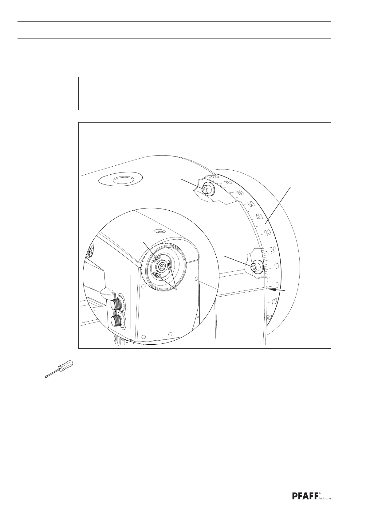
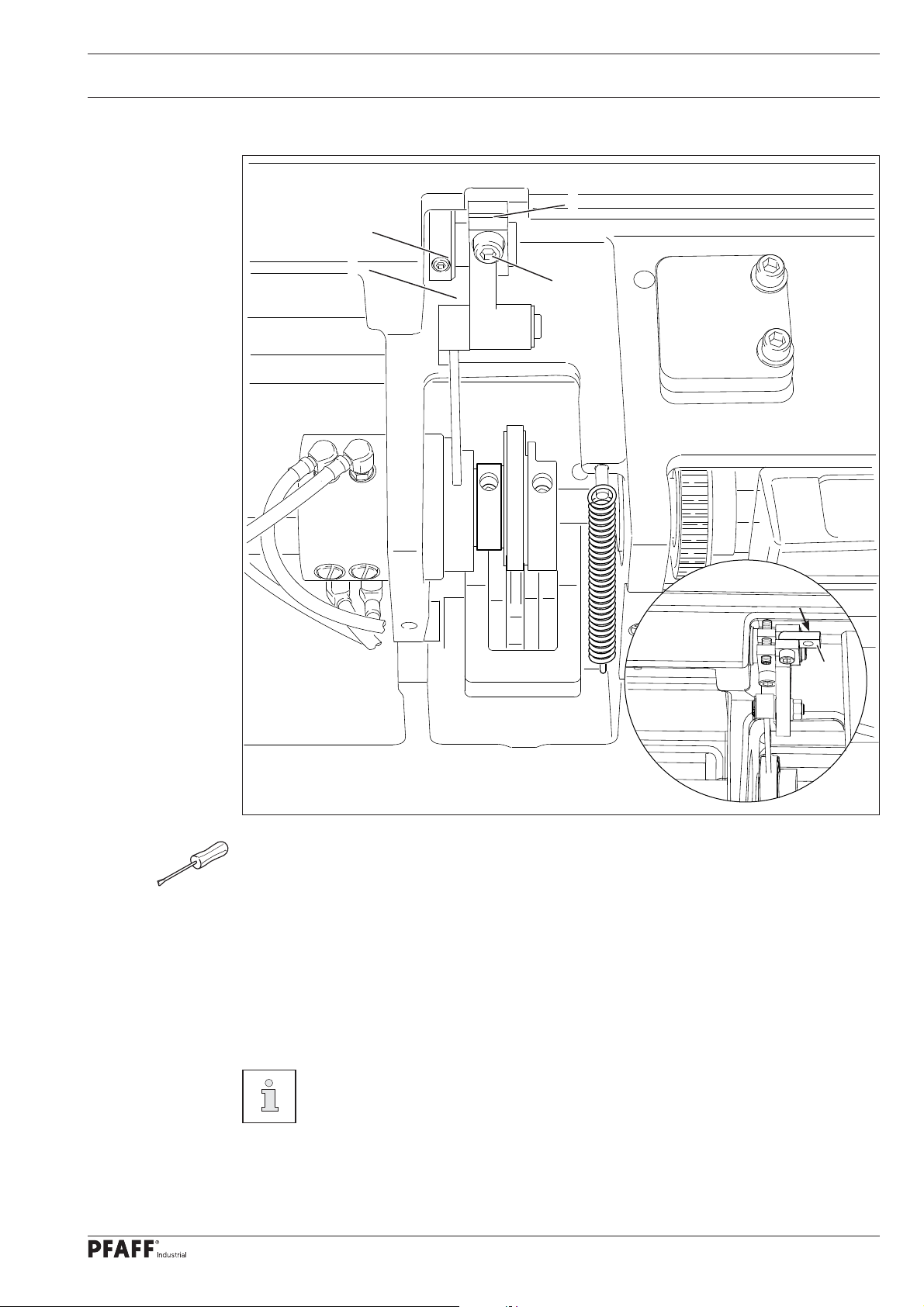
.05.01 Basic position of the balance wheel (adjustment aid)
1
Requirement
When the needle bar is positioned at t.d.c., the marking "0" on the scale should be level
with the top edge of the belt guard (see arrow).
Fig. 1 - 01
2
1
3
2
3
127-01
● Adjust the scale dial 1 ( depending on model screws 2 or 3 ) in accordance with the re-
quirement.
6
Page 7
Adjustment
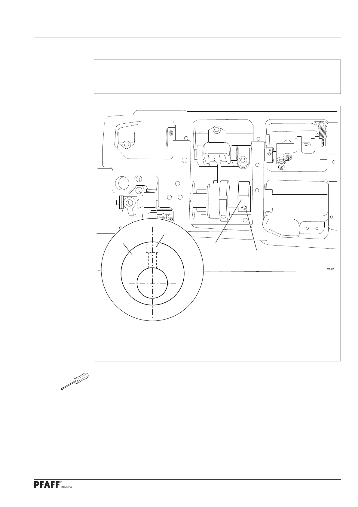
1.05.02 Balance weight
Requirement
When the needle bar is positioned at b.d.c. (balance wheel position 180°) the largest ec-
centricity of the balance weight 1 should be at the top.
2
1
1
2
Fig. 1 - 02
● Adjust balance weight 1 (screw 2) in accordance with the requirement.
7
Page 8
Adjustment
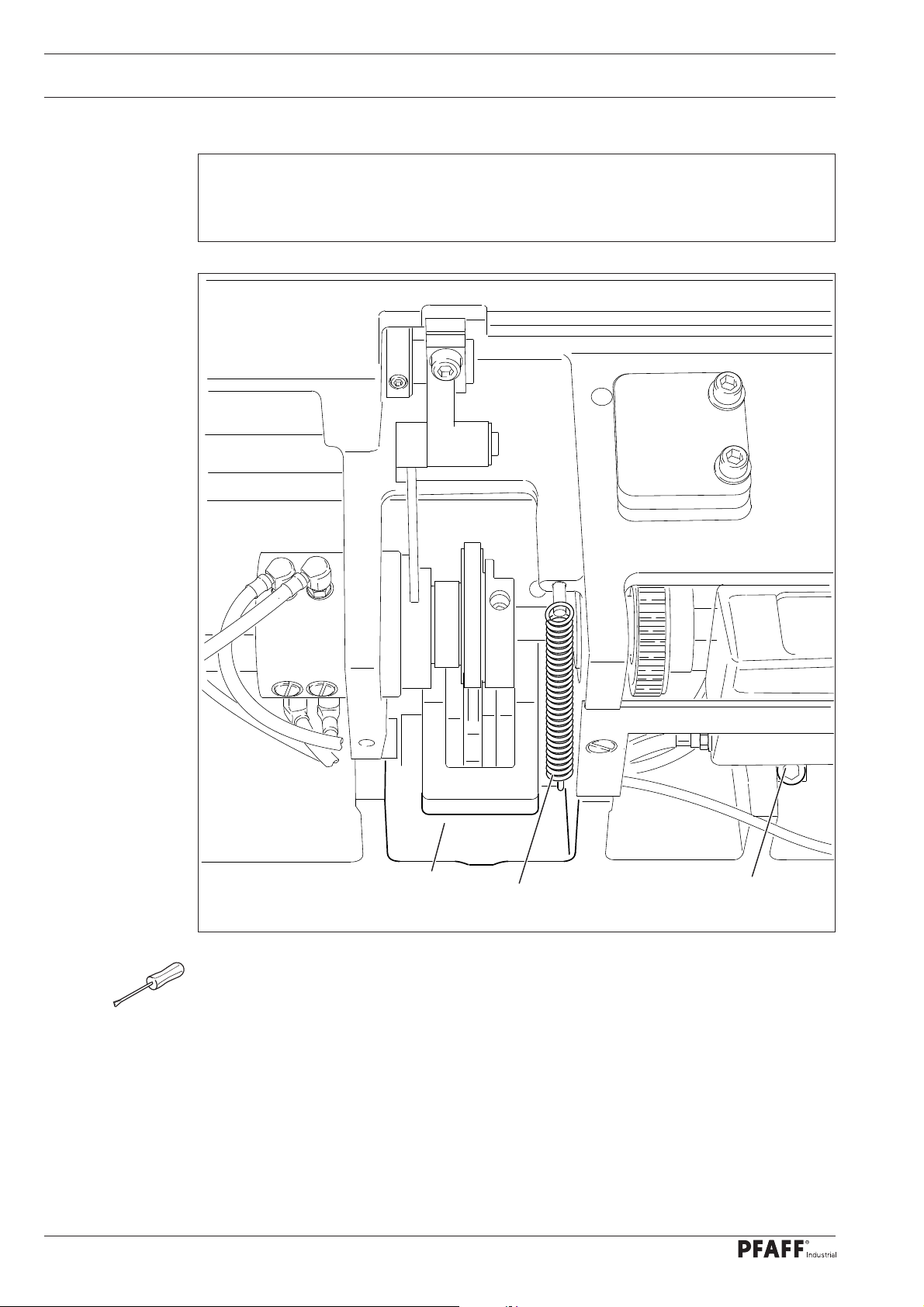
1.05.03 Zero position of the unison feed
Requirement
When the stitch length is set at "0", the top and bottom feed dogs and the needle bar
should not make any feeding motion when the balance wheel is turned.
2
Fig. 1 - 03
● Remove spring 1.
● Adjust crank 2 (screw 3) in accordance with the requirement.
● Replace the spring 1.
1
3
8
Page 9

Adjustment
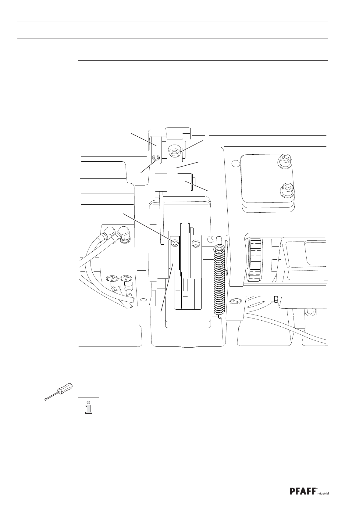
1.05.04 Feeding motion of the unison feed
Requirement
When the needle bar is positioned at b.d.c. (balance wheel position 180°), and the ma-
ximum stitch length is set, the top and bottom feed dogs and the needle bar should not
make any feeding motion when the reverse-feed lever is pressed.
2
1
Fig. 1 - 04
● Adjust eccentric 1 (screws 2) in accordance with the requirement. Make sure that the
cut-out (see arrow) is visible.
9
Page 10
Adjustment
1.05.05 Lifting motion of the bottom feed dog
Requirement
When the balance wheel is positioned at 180°, the feed dog should be at t.d.c.
3
6
5
4
7
2
1
Fig. 1 - 05
● Adjust eccentric 1 (screws 2) in accordance with the requirement.
10
Use the kit with the Order No. 91-501 399-90 to deactivate the transporter lif-
ting movement.
● Install assembly and adjust
● Remove collar 3 (screws 4) and crank 5 (screw 6, nut 7).
● Mount the preassembled parts of the kit as shown in fi gures 1 - 05a.
● Adjust bottom transporter height and stroke movement where required.
Page 11
Adjustment
8
10
9
11
8
Fig. 1 - 05a
Activate lifting movement
● Lifting movement is activated if connection part 8 is swiveled in as shon in
fi gures 1 - 05a, and screws 9 (M6 x 16) and 10 (M5 x 16) have been attached.
Deactivate lifting movement
● Remove screws 9 and 10 and swivel connection part 8 (screw 11 ) towards the right.
● Replace screw 9 with a screw M6 x 25.
● Replace screw 10 with a threaded pin M5 x 25 and tighten to stop.
Adjust transporter height with deactivated stroke movement so that the upper
edge of the transporte is at the height of the upper edge of the needle plate.
Adjust the transporter height once again with the stroke movement activated,
as described in chapter 1.05.06.
11
Page 12

Adjustment
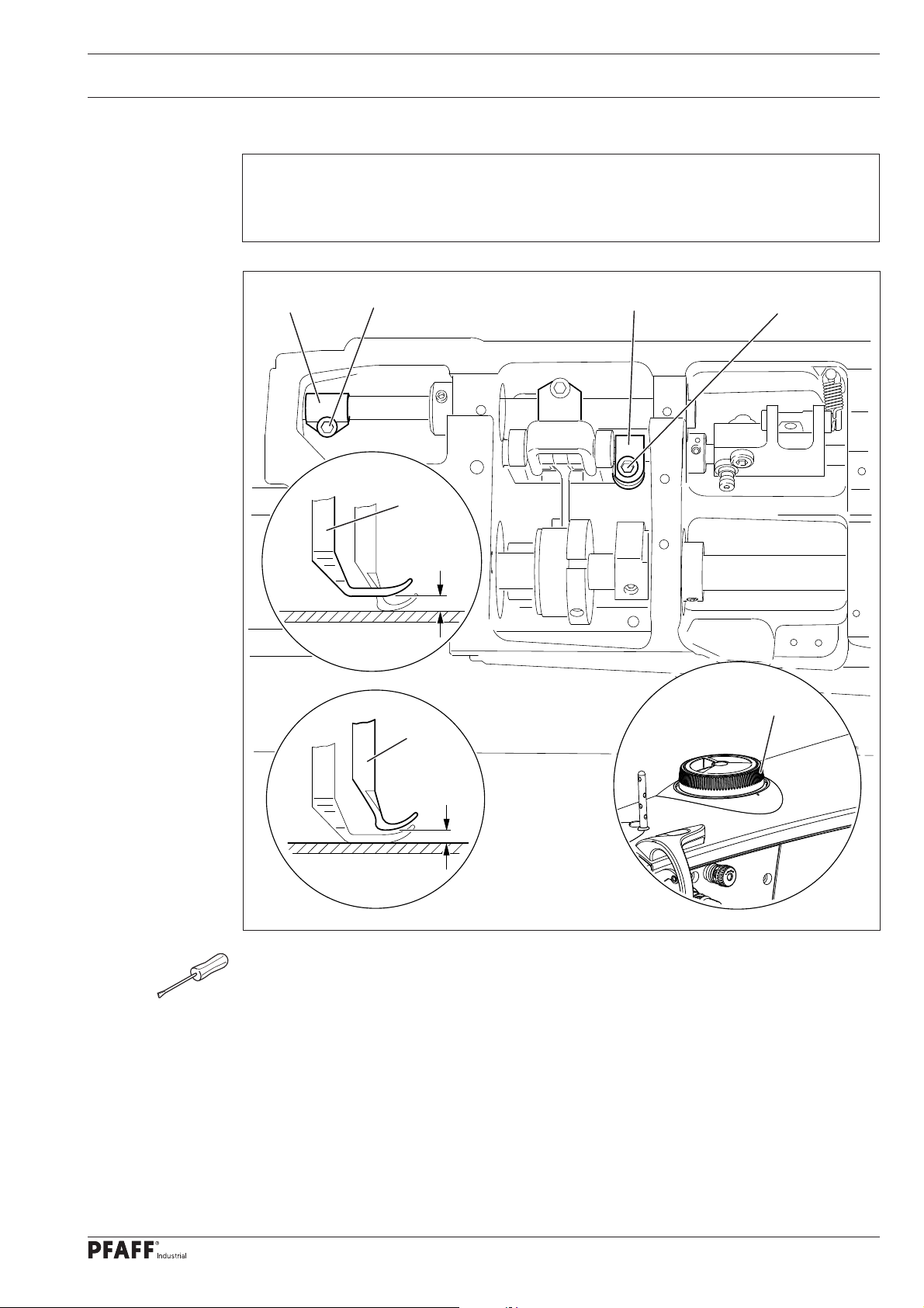
1.05.06 Height of the bottom feed dog
Requirement
1. When the needle bar is positioned at b.d.c. (balance wheel position 180°), the bottom feed
dog should be positioned 0.5 mm horizontally above the top edge of the needle plate,
when crank 5 is in the centre of the slot.
2. In the direction of sewing, the bottom feed dog should be positioned in the centre of
the needle plate slot.
1
2
2
0,5 mm
5
6
12
3
4
4
Fig. 1 - 06
● Turn lifting crank 1 (screws 2) and eccentric sleeve 3 (screws 4) according to Require-
ment 1, and set feed dog in centre of needle-plate slot as shown in Requirement 2.
The height of the bottom feed dog can also be increased or reduced as required
by moving crank 5 (nut 6) up or down.
Page 13
Adjustment
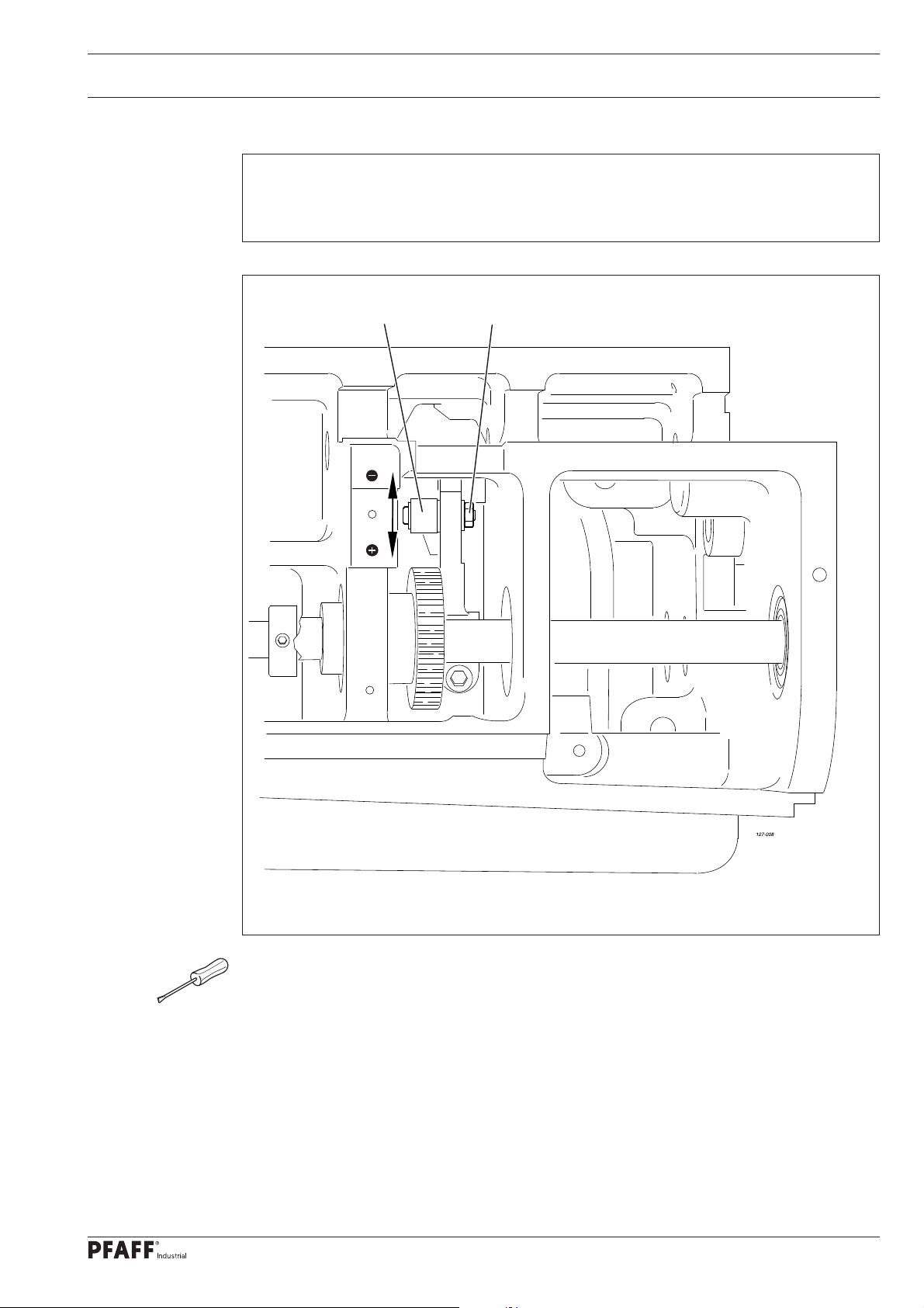
1.05.07 Feeding stroke difference
Requirement
With the maximum stitch length set, when the balance wheel is turned the feeding stro-
kes of the needle and the bottom feed dog should be the same.
1
2
Fig. 1 - 07
● With connecting rod 1 (nut 2) increase ("+") or reduce (-) the needle feed stroke in
accordance with the requirement.
13
Page 14
Adjustment
1.05.08 Preliminary adjustment of the needle height
Requirement
When the needle bar is positioned at t.d.c. (balance wheel position 0°), the clearance
between the needle point and the needle plate should be 22 mm.
2
1
1
3
22 mm
Fig. 1 - 08
● Without turning it, re-position needle bar 1 (screw 2) in accordance with the
requirement.
Make sure that needle bar 1 and foot 3 do not collide.
14
Page 15
Adjustment
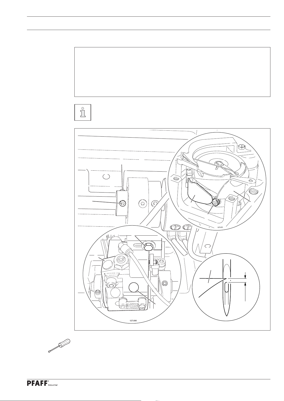
1.05.09 Needle rise, hook clearance, needle height and needle guard
Requirement
With the stitch length set at "4.5" and in the needle rise position (see table)
1. The hook point 6 should be positioned at "needle centre" with a hook-to-needle clea-
rance of 0.05 – 0.10 mm.
2. The top of the needle eye should be positioned 0.8 mm below hook point 6. and
3. and needle guard 7 must touch the needle just lightly.
Needle rise position
Model C: Balance wheel position 204° / 2.0 mm
Model D: Balance wheel position 206° / 2.4 mm
5
5
Fig. 1 - 09
7
1
8
4
3
6
0,8 mm
2
● Loosen both screws of the gear drive of hook 1 (under cover 2).
● Adjust hook 1 and hook bearing 3 (screws 4 and 5) in accordance with requirement 1.
● Without turning it, re-position the needle bar in accordance with the requirement 2, also
see Chapter 1.05.08 Preliminary adjustment of the needle bar.
15
Page 16

Adjustment
● Adjust needle guard 7 (screw 8) in accordance with requirement 3.
If the needle size is changed, a quick adjustment of hook bearing 3 is possible,
after loosening screws 4 and 5.
16
Page 17
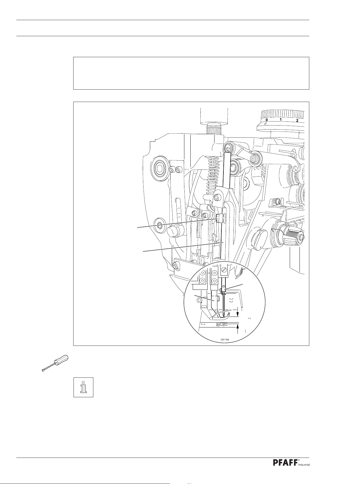
Adjustment
1.05.10 Top feed stroke
Requirement
With adjustment wheel 1 set at "5", the top feed dog 7 and presser foot 4 should each
rise by 5.0 mm.
5
6
2
3
4
5 mm
1
7
5 mm
Fig. 1 - 10
● Remove the bottom feed dog and set adjustment wheel 1 at "5".
● Loosen the screws of the needle plate, place the metal gauge over the opening of the
needle plate slot so that both sewing feet can be lowered onto the metal gauge.
● For the preliminary adjustment, adjust crank 2 (screw 3) so that there is a clearance of 5
mm between presser foot 4 and the needle plate.
● Adjust crank 5 (screw 6) so that top feed dog 7 and presser foot 4 have the same stroke.
● Check the adjustment in accordance with the requirement, and correct if necessary.
17
Page 18

Adjustment
1.05.11 Top-feed lifting motion
Requirement
The top feed dog should just have reached the needle plate when the presser foot lift is
set at 5 mm and the needle descending from above is 2 mm above the needle plate.
1
2
Fig. 1 - 11
● Turn eccentric 1 (screw 2) in accordance with the requirement.
2 mm
18
Page 19

Adjustment
1.05.12 Adjusting the potentiometer for speed reduction
1
.05.12 .01 Machines with P74 ED-L
● Switch on the machine
● Set the smallest stroke "0".
● Using the stroke adjustment function, call up the smallest stroke (LED off), see the Cont-
rol Panel Instruction Manual.
● Call up parameter "501" and press key "C+" to save the bottom value.
● Set the inner adjustment wheel at maximum stroke "9".
● Using the stroke adjustment function, call up the largest stroke (LED on), see the Control
Panel Instruction Manual.
● Call up parameter "502" and press key "C+" to save the top value.
The speed is adjusted in accordance with Chapter 3.03 Maximum Speed in
the Instruction Manual.
1.05.12.02 Machines with PF 321
● Press "P" on the control panel, while simultaneously switching the machine on.
● Enter the code 3112 via the numbered keys and confi rm by pressing "E".
● Select parameter 501 via the numbered keys and confi rm by pressing "E".
● Set the smallest stroke "0".
● Using the stroke adjustment function, call up the small stroke (LED off), see instruction
manual.
● Take over the value displayed under parameter 501 by pressing "+".
● Select parameter 502 via the numbered keys.
● Set the largest stroke "0".
● Using the stroke adjustment function, call up the large stroke (LED on).
● Take over the value displayed under parameter 502 by pressing "+".
● Press "P" twice to quit the input level
● The new values are taken over when sewing is started, and these are maintained
evenafter the machine is switched off.
The speed is adjusted in accordance with Chapter 3.03 Maximum Speed
in the instruction manual.
Under parameter 117 the speed at max. stroke adjustment can be reduced
again.
19
Page 20

Adjustment
1.05.13 Bobbin case opener stroke
Requirement
When the balance wheel is turned
1. The beak 4, when it is at the right point of reversal of the bobbin case opener 1,
should rise from the needle plate 5 by the thickness of the thread.
2. The bobbin case opener 1 should be at its left point of reversal when the balance
wheel is positioned at "10°".
5
1
4
2
6
3
Fig. 1 - 13
● Adjust bobbin case opener 1 (screw under cover 2) in accordance with requirement 1.
● Adjust the eccentric (screw under cover 3) in accordance with requirement 2.
20
The thread must be able to pass unhindered between bobbin case opener 1
and bobbin case 6.
Page 21

Adjustment
1.05.14 Adjusting the shortened trim stitch
Requirement
For the trim stitch the machine should carry out a stitch length of 0.5 – 1.0 mm.
2
2
Fig. 1 - 14
● Adjust lever 1 (screws 2) in accordance with the requirement.
1
21
Page 22

Adjustment
1.05.15 Bobbin winder
Requirement
1. When the bobbin winder is engaged, the winding spindle must be driven reliably.
When it is disengaged, friction wheel 3 should not be touching drive wheel 1.
2. When it is switched off, the bobbin winder must click securely into its end position
(knife raised).
1
2
Fig. 1 - 15
● Adjust drive wheel 1 (screw 2) in accordance with the requirement.
3
22
Page 23

Adjustment
1.05.16 Thread check spring and thread regulator
Requirement
1. The movement of thread regulator 3 must be completed when the needle point enters
the material.
2. When the thread loop is at its largest while being passed around the hook, the check
thread spring 3 should rise slightly from the rest 1.
1
3
Fig. 1 - 16
● Position rest 1 (screw 2) in accordance with requirement 1.
● Turn sleeve 4 (screw 2) to adjust the tension of thread check spring 3.
● Position thread regulator 5 (screw 6) in accordance with requirement 2.
6
5
4
2
For technical reasons it may be necessary to deviate from the indicated spring
stroke or spring tension.
Move thread regulator 5 (screw 6) towards ("+") (= more thread) or ("-") (= less
thread).
23
Page 24

Adjustment
1.05.17 Sewing foot pressure
Requirement
The material should be fed properly even at maximum speed and with the smallest stroke.
1
24
Fig. 1 - 17
● Turn adjustment wheel 1 in accordance with the requirement.
Page 25

Adjustment
1.05.18 Lubrication
Requirement
After a running time of 10 seconds a thin fi lm of oil should be visible on paper strip 1
when this is held over the hook.
2
1
Fig. 1 - 18
● Check that the machine is fi lled with oil and that the oil lines are free of air.
● Run the machine for 2 – 3 min.
Do not put your hands into the needle area when the machine is running!
Danger of injury from moving parts!
● With the machine running, hold paper strip 1 against the hook and check the require-
ment.
● If necessary, regulate amount of oil with screw 2.
25
Page 26

Adjustment
1.05.19 Limiting the stitch length
When exchanging the parts kit with stitch lengths differing from the as-deliv-
ered state of the machine, limit the max. stitch length using stitch adjuster 4.
7
Fig. 1 - 19
● Set the desired max. stitch length at control button 1
(on model CN9 = 9.0 mm, on model DN12 = 12 mm)
● Remove adjustment knob 1 (screws 2) and scale dial 3.
● Remove adjustment unit 4 (screws 5).
● Bring lineal 6 (screw 7) to the unit using stitch adjuster 4 (see arrow).
● Replace adjustment unit 4, scale dial 3 and adjustment knob 1.
5
6
4
3
2
1
26
Page 27

Adjustment
1.05.20 Speed reduction
Requirement
If a stitch length longer than 9 mm is set, the speed reduction switch 3 must be pressed.
1
2
2
1
3
Fig. 1 - 20
● Adjust retaining plate 1 (screws 2) in accordance with the requirement.
128-081
27
Page 28

Adjustment
1.05.21 Re-engaging the slip-clutch
Clutch 1 is adjusted at the works. In the case of a thread jamming, clutch 1 will
disengage, in order to avoid damage to the hooks.
The following describes how to re-engage clutch 1.
1
28
Fig. 1 - 21
● Remedy jammed thread fault.
● Hold clutch 1 fi rmly, as shown in Fig. 13-22, and turn the balance wheel until clutch 1
re-engages.
Page 29

Adjustment
1.06 Adjusting the thread trimmer -900/81
.06.01 Resting position of roller lever/radial position of control cam
1
Requirement
1. When the take-up lever is at t.d.c. (balance wheel position 60 °), control cam 1 should
just have moved roller lever 5 into its basic position.
2. When the thread trimmer is in its resting position, there should be a clearance of
0.1 mm between roller lever 5 and control cam 1.
4
3
5
Fig. 1 - 22
● Adjust control cam 1 (screws 2) in accordance with requirement 1.
0,1 mm
1
2
● Adjust screw 3 (nut 4) in accordance with requirement 2.
29
Page 30

Adjustment
1.06.02 Position and height of the thread catcher
Requirement
When the needle bar is positioned at b.d.c. (balance wheel position 180°) the edges of
thread catcher 3 and knife 5 should be fl ush (see arrow).
Fig. 1 - 23
4
1
2
5
3
127-096
30
● Press roller lever 1 against control cam 2.
● Adjust thread catcher 3 (screw 4) in accordance with the requirement
The height of thread catcher 3 is pre-set by the manufacturer and, if necessary,
it can be adjusted with washers under thread catcher 3 on the base of the hook
bearing.
Page 31

Adjustment
1.06.03 Knife pressure
Requirement
When the front edge of thread catcher 3 is 5 – 6 mm in front of the knife blade, the knife
4 should be touching the catcher edge with slight pressure.
4
5
6
3
1
2
5 - 6 mm
Fig. 1 - 24
● Bring the take-up lever to its b.d.c and press roller lever 1 into the control cam 2.
● Turn the balance wheel until the front edge of catcher 3 is at a distance of 5 – 6 mm from
the blade of knife 4.
● Swing knife bearing 5 (screw 6) in accordance with the requirement.
After completing the adjustment, recheck the position of the thread catcher in
accordance with Chapter 1.06.02 Position and height of the thread catcher.
31
Page 32

Adjustment
1.06.04 Bobbin thread clamp spring
Requirement
When the thread trimmer is in its cutting position, the clamp spring should slightly touch
the thread catcher and hold the thread reliably.
2
1
Fig. 1 - 25
● Adjust clamp spring 1 (screw 2) in accordance with the requirement.
● Carry out the cutting operation by hand and check the setting. Readjust if necessary.
32
Page 33

Adjustment
1.06.05 Manual cutting test
Requirement
1. 1. When moving forward, thread catcher 1 must not move bobbin thread 3
2. When thread catcher 1 is at its front point of reversal, bobbin thread 3 should be in the
centre of the marked area (see arrow).
3. After the cutting operation has been completed, needle and bobbin thread should be
cut neatly and bobbin thread 3 held.
2
3
Fig. 1 - 26
● Sew a few stitches.
1
3
● Switch off the main switch and the compressed air.
● Carry out a manual cutting test.
● Check requirement 1. If necessary, readjust thread catcher 1 in accordance with Chapter
1.06.02 Position and height of the thread catcher.
● Check requirement 3. If necessary, readjust bobbin thread clamp spring 2 in accordance
with Chapter 1.06.04 Bobbin thread clamp spring.
33
Page 34

Adjustment
Consult the instruction manual for the drive for a description of the parameter
settings and a list of the parameters.
34
Page 35

Adjusting
1.07 Adjusting the thread trimmer device -900/82
.07.01 Preliminary testing
1
1
.07.02 Assembly of the thread clamp carrier and thread catcher
1
2
Fig. 1 - 27
● Assemble thread clamp carrier 1 and thread catcher 2 depending on the hock size:
- Large hock assembly (bobbin diameter 26 mm) is shown in Fig. 1 - 27.
- Extra large hock assembly (bobbin diameter 32 mm) is shown in Fig. 1 - 27a.
1
2
Fig. 1 - 27a
1.07.03 Check settings according to the following chapter:
● Check the home position of the handwheel.
● Check lower, upper and needle feed sliding movement.
● Check bottom transporter lifting movement..
35
Page 36

Adjusting
1.07.04 Needle postition in sewing direction
Rule
At stitch length setting "0", the needle in sewing direction should pierce the middle of the
setting gauge hole 1.
3
1
Fig. 1 - 28
● Unscrew the needle plate and bottom transporter..
● Insert a 100/100 mm thick needle.
● Unscrew setting gauge 1 (Order No. 61-111 689-07).
● Adjust needle bar 2 (screw 3) in accordance with the rule.
● Unscrew the setting gauge again.
● Reassemble the bottom transporter.
2
36
Page 37

Adjusting
1.07.05 Bottom transporter in sewing direction
Rule
At stitch length setting "0", the needle in sewing direction should pierce the middle of the
stitch hole in the bottom feed 1.
3
5
4
Fig. 1 - 29
● Adjust bottom feed 1 (screw 2) in accordance with the rule.
● Mounting the needle-plate.
1
2
Of you mounte the needle-plate, make sure that the
ball-joint 3 of the knife 4 is in the cut-out
37
Page 38

Adjusting
1.07.06 Blade position
Rule
If the knife is max. to the front and thestitch-length setting "0" the edge 5 of the knife 4
should be 0.2 mm a way from the feed dog 6
1
Fig. 1 - 30
● Set stitch length to "0"
4
2
0,2 mm
3
5
4
6
38
● Move lever 1 to its stop to the front
● Move support 2 (screw 3) acocording to the setting
Page 39

Adjusting
1.07.07 Thread catcher height
Rule
When positioning the thread catcher 2 under the setting gauge 1, the thread catcher 2
should directly touch the setting gauge 1 without turning it.
1
2
3
4
Fig. 1 - 31
● Place the setting gauge 1 (Order No. 61-111 689-07) in the needle plate recess, so that it
stands above the thread catcher 2 (see magnifi cation).
The height setting is factory preset.
Any possible correction required can be carried out by placing a 0.2 mm thick
spacing washer underneath (Order No. 12-360 061-05) between part 3 and
part 4.
39
Page 40

Adjusting
1.07.08 Thread catcher postition in sewing direction
Rule
At stitch length setting "0" and the thread catcher 4 in the front turning point position, a
gap of 20 mm should exisit between the thread catcher point and the middle stitch hole.
2
4
20 mm
3
5
Fig. 1 - 32
● Bring the roller lever 1 (screw 2) to the lowest trim curve position 3.
● Turn thread catcher 4 in accordance with the rule
● Make sure that the catcher 5 has no axial player when tighten the screw 2.
1
40
Page 41

Adjusting
1.07.09 Thread catcher postion crossways to sewing direction
Rule
In the max. forwards position of the catcher 1, the right edge of the catcher and the right
edge of the feed dog 3 be lined up.
1
3
2
Fig. 1 - 33
● Move thread catcher 1 (screws 2) in accordance with the rule..
41
Page 42

Adjusting
1.07.10 Position of the control curve
Regel
1. In the hand wheel position 305°, the catcher should just start with its movment.
2. When the thread trimmer attachment is in its idle state, a gap of 0.1 mm should exist
between the roller lever 5 and the control curve 1.
4
3
0,1 mm
5
1
Fig. 1 - 34
● Turn control curve 1 (screws 2) in accordance with rule 1.
● Adjust screw 3 (nut 4) in accordance with rule 2.
2
42
Page 43

Adjusting
1.07.11 Thread clamp
Rule
1. The right edge of the ripper 1 should be fl ush with the right edge of the catcher 5 in it´s
rest position.
2. The ripper 1 should sllightly touch the catcher and the top thread gets easy pulled out
of the ripper.
5
1
Fig. 1 - 35
● To see better, remove the throat-plate and the feed dog.
● Move the thread-ripper 1 (screw 2) according to the setting.
● Move support 3 (screw 4) according to the setting.
2
3
4
● Fix the Throad-plate and the feed dog..
43
Page 44

Adjusting
1.07.12 Parameter values
The following parameters has to be set diffrent to the regulare
P74 ED instruction manual.
Group
Parameter
Description
3
309 Position short trimmer on B, C 0 - 255 180
310 Functions A16
0 = no function
1 = midle guide
2 = short trimmer
312 Selection of midle guide B, C ON - OFF OFF
User level
B, C 0 - 2 2
Setting range
Set value
314 Funkctions A7
0 = no function
1 = edge trimmer
2 = thread-pulling sewing start
315 Funkctions A15
0 = no function
1 = Faclean thread-monitor
2 = Thread-pulling at sewing-start
316 Position to pull thread at seam-start B, C 0 - 255 235
317 Time to pull the thread at sewing-start B, C 10 - 1000 100
6
657 Stitch protection / knotting B, C ON - OFF ON
7
702 1 Needle position (down) B, C 0 - 255 20
703 Thread lever position up B, C 0 - 255 235
705 End trim signal1 B, C 0 - 255 210
706 Start trim signal B, C 0 - 255 100
707 Start thread tension release B, C 0 - 255 190
9 989
Thread-nipper at sewing-start
0 = Thread-nipper off
1 = Thread-nipper without foot-lift
2 = Thread-nipper with foot-lift
B, C 0 - 2
B, C 0 - 2
B, C 0 - 2
0
0
1
44
Page 45

Block diagram Version 28.03.07
2 Circuit diagrams
.01 Block diagram PFAFF 2545 and 2546 BASIC with control pack P45 PD-L
2
2545 BASIC
2546 BASIC
H1
Synchronizer PD 6
BDF - PICO TOP
A2
S1
Control unit QA40 PD
A1
X3
Ministop drive unit
(long) with incremental
transducer
X1
X2
X7
LED
LED
power
supply
Netzteil
unit
X4
PC
for
software
download
X4
Q1
Power switch
Mains plug
45
Page 46

Circuit diagrams
2.02 Circuit diagrams PFAFF 2545 and 2546 BASIC
Reference list for the Circuit diagrams 91-191 523-95
A1 Controller P45 PD-L
A2 Control panel (PicoTop)
H1 Sewing lamp
M1 Sewing motor
Q1 Main switch
S1 Pedal speed control unit
X1 Sewing motor
X2 Incremental transmitter
X7 Synchronizer PD 6
X3 Speed control unit
X4 PicoTop control panel or RS 232 interface (PC)
X5 Input/output plug
X8 Light barrier plug (optional)
46
Page 47

Circuit diagrams Version 27.07.07 91-191 523-95 Part 1
47
Page 48

91-191 523-95 Part 2 Version 27.07.07 Circuit diagrams
48
Page 49

Block diagram Version 10.08.10
2.03 Block diagram PFAFF 2545 2546 PLUS with control pack P74 ED-L
Synchronizer PD 6
Optional
Light
barrier
A 20
A20
Y3, Y4, Y5, Y6, Y9
Y8, Y14, Y1X, R1
XA20
Optional
B30
2545 PLUS
2546 PLUS
(long) with incremental
XS27
XS29
S26
Ministop drive unit
transducer
BDF - PICO TOP
LED
power
supply
unit
A2
PC
X7
Control unit P74 ED
A1
X3
S1.1
X5
KS
X1
X2
X2.1
X2
Q1
Power switch
Mains plug
X2.2
X2.2
Adapter
X4
for
software
download
X0
49
Page 50

Circuit diagrams
2.04 Circuit diagrams PFAFF 2545 and 2546 PLUS
Reference list for the Circuit diagrams 91-191 519-95
A1 Steuergerät P74 ED-L
A1 Controller P74 ED-L
A2 Control panel (PicoTop)
A14 Sewing head recognition (OTE)
A15 Oil sensor (2C-Bus)
A16 Keyboard (2C-Bus)
A20/1 Bobbin thread monitor 1 (optional)
A20/2 Bobbin thread monitor 2 (optional)
B30 Slider monitoring (optional)
B41 Oil sensor (2C-Bus)
H1 Sewing lamp
R1 Potentiometer for reduced speed
during stroke adjustment
M1 Sewing motor
Q1 Main switch
S1.1 Pedal speed control unit
S1 Key 1 depending on parameter
other function
S2 Key 2 depending on parameter
other function
S3 Key 3 depending on parameter
other function
S4 Key 4 depending on parameter
other function
S5 Key 5 depending on parameter
other function
S6 Key 6 depending on parameter
other function
S7 Key 7 depending on parameter
other function
S8 Key 8 Emergency off
S26 Start inhibitor
S27 Stroke adjustment
S28 Speed limitation from 9mm
stitch length on
S29 Centre guide
X0 RS232 interface (PC)
X1 Sewing motor
X2 Incremental transmitter
X2.1 Incremental transmitter
X2.2 Synchronizer PD 6
X3 Speed control unit
X4 PicoTop control panel
X5 Input/output plug
X7 Light barrier plug & bobbin thread
monitor (optional)
XA14 A14 Sewing head recognition (OTE)
XA15.1 A15 Oil sensor (2C-Bus)
XA15.2 A15 Oil sensor (2C-Bus) >
A16 Keyboard (2C-Bus)
XA20 A20 Bobbin thread monitor (optional)
XR1 R1 Potentiometer for reduced speed
during stroke adjustment
XS26 Start inhibitor
XS27 Stroke control
XS28 Speed limitation from 9mm
stitch length on
XS29 Centre guide
XY3 Y3 Thread clamp (-909/..)
XY4 Y4 Presser foot lift (-910/..)
XY5 Y5 Backtacking device (-911/..)
XY6 Y6 Stroke adjustment (-918/26)
XY8 Y8 Thread tension release
XY9 Y9 Thread trimmer (-900/..)
XY12 Y12 2nd stitch length quick
adjustment (-918/29)
XY13 Y13 Trim stitch
XY14 Y14 Thread tension control
XY15 Y15 Hook cleaning A20 Bobbin
thread monitor (-926/..)
Y3 Thread clamp (-909/..)
Y4 Presser foot lift (-910/..)
Y5 Backtacking device (-911/..)
Y6 Stroke adjustment (-918/26)
Y8 Thread tension release
Y9 -900/.. Thread trimmer
Y12 2nd stitch length (-918/29)
Y13 Trim stitch
Y14 Thread tension control
Y15 Hook cleaning A20 Bobbin thread
monitor (-926/..) optional
Y16 Centre guide unit (only on the 2546)
or -900/82
50
Page 51

Circuit diagrams Version 10.08.10 91-191 519-95 Part 1
51
Page 52

91-191 519-95 Part 2 Version 20.04.12 Circuit diagrams
52
Page 53

Circuit diagrams Version 20.04.12 91-191 519-95 Part 3
53
Page 54

91-191 519-95 Part 4 Version 20.04.12 Circuit diagrams
54
Page 55

Block diagram
2.05 Block diagram PFAFF 2545/46 PLUS with PF 321
PD 6
UFW
(Option)
Y3, Y4, Y5, Y6,
Y8, Y14, Y1X, R1
SWG
2545 / 46
LS
(Option)
BDF
X 5
ST 2
BDF = Control panel
UWF = Lower thraed monitor
SWG = Speedcontrolunit
KS = Knee switch
KS
B 41
B 2B 80
Mains plug
Adapter
1113229
B 18
B 776
USB
for Software
download
55
Page 56

PFAFF Industriesysteme
und Maschinen AG
Hans-Geiger-Str. 12 - IG Nord
D-67661 Kaiserslautern
Telefon: +49 - 6301 3205 - 0
Telefax: +49 - 6301 3205 - 1386
E-mail: info@pfaff-industrial.com
Gedruckt in der BRD / Printed in Germany / Imprimé en la R.F.A. / Impreso en la R.F.A
© PFAFF Industriesysteme und Maschinen AG 2009, PFAFF is the exclusive trademark of VSM Group AB.PFAFF Industriesysteme und Maschinen AG is an authorized licensee of the PFAFF trademark.
 Loading...