

Pfaff PowerLine 2231, PowerLine 2235, PowerLine 2542, PowerLine 2545, PowerLine 2546 Setup Instructions
Page 1

2231
2235
SET-UP INSTRUCTIONS
2542
2545
2546
296-12-19 216/002
Aufstellanleitung engl. 02.13
Page 2

The reprinting, copying or translation of PFAFF Service Manuals - whether in whole
or in part - is only permitted with our prior consent and with reference to the source.
PFAFF Industriesysteme
und Maschinen AG
Hans-Geiger-Str. 12 - IG Nord
D-67661 Kaiserslautern
Page 3

Index
Contents ..................................................................................Page
1 General Notes ......................................................................................................................4
1.01 Explanation of the symbols ....................................................................................................4
2 Scope of delivery ................................................................................................................. 5
2.01 Sewing machine accessories ................................................................................................5
2.02 Accessories for the sewing machine drive with PicoDrive P45 PD2-L .................................. 7
2.03 Accessories for the sewing machine drive with EcoDrive P74 ED-L......................................8
3 Stand and table top ........................................................................................................... 10
3.01 Table top cutout ................................................................................................................... 10
3.02 Assembly drawing for the table .......................................................................................... 13
3.03 Assembling the stand and table top .................................................................................... 16
3.05 Adjusting the table-top height .............................................................................................. 17
4 Assembling the sewing machine drive ............................................................................ 18
4.01 Assembling the motor ......................................................................................................... 18
4.02 Assembling the motor, speedcontrolunit and controlbox .................................................... 19
5 LED-Lamp (optional) .......................................................................................................... 21
5.01 Assembling the LED lamp ................................................................................................... 21
5.02 Fitting the transformer to the LED lamp .............................................................................. 22
6 Installation .......................................................................................................................... 23
6.01 Setting the sewing machine into the stand .........................................................................23
6.02 Fitting the V-belt and assembling the bottom belt guard...................................................... 24
6.03 Assembling the thread guide and take-up lever guard ......................................................... 25
6.04 Assembling the top V-belt guard and sewing head support ................................................. 26
6.05 Mounting the control panel .................................................................................................. 27
6.06 Connecting the plug-in connections and earth cables ......................................................... 28
6.07 Block diagram ...................................................................................................................... 29
6.08 Mounting / connecting the maintenance unit ...............................................................................34
7 Commissioning .................................................................................................................. 35
7.01 Switching the machine on/off ..............................................................................................35
7.02 Machine drive home position ...............................................................................................36
Page 4
General Notes
1 General Notes
The machine may only be set-up and commissioned by qualifi ed personnel!
All notes in Chapter 1 Safety of the Instruction Manual must be observed!
There must be suitable electrical connections at set-up site, see Chapter 3
Specifi cations of the Instruction Manual. A fi rm, level surface and adequate
lighting must also be available at the set-up site.
If the machine was delivered without a table, both the stand and the table top
intended for use must be constructed for a weight of at least 100 kilos.
1.01 Explanation of the symbols
In these Set-Up Instructions, symbols emphasize operations to be carried out or
important information. The symbols used have the following meaning:
Note, information
Service, repair, adjustment, maintenance
(work to be carried out by qualifi ed staff only
Safety symbols
Danger!
Points to be observed.
Danger of injury for operating and specialist personnel!
4
Page 5
Scope of delivery
2 Scope of delivery
The scope of delivery of the machine depends on the order.
Before setting up the machine, check whether all the required parts have been included.
The following description only applies to one special sewing machine, for which all individual
components have been delivered by the PFAFF Industriesysteme und Maschinen AG.
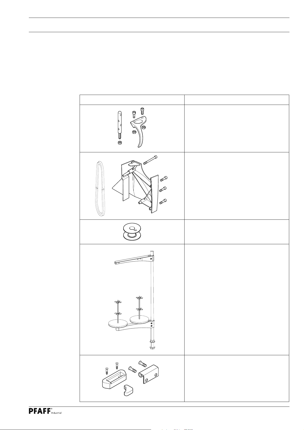
2.01 Sewing machine accessories
Sewing machine accessories Description / No. of pieces
Thread guide and take-up lever guard
with screws and nuts (1x)
V-belt and
belt guard with screws (1x)
Bobbin (5x)
Reel stand complete (1x)
Rear rubber pads with screws
Front rubber pads
Hinge with screws
5
Page 6

Scope of delivery
Sewing machine accessories Description / No. of pieces
Sewing head support (1x),
Tilt lock (1x)
(only on the PFAFF 2542, 2545 and 2546)
Oil pan with screws and washers
Industrial
Oilcan (1x),
Sachet with 80 ml oil,
Dusting brush (1x)
Sewing head protective cover (1x)
Allan key 3 mm (1x),
Screwdriver large (1x),
Screwdriver small (1x)
Control panel bracket
(with motor AB 321 + PF 321 only)
Set-up instructions,
instruction manual for the machine
Earth cable 2231 + 2235 (2x), 2542, 2545
and 2546 (3x) , screw and washers
6
Page 7
Scope of delivery
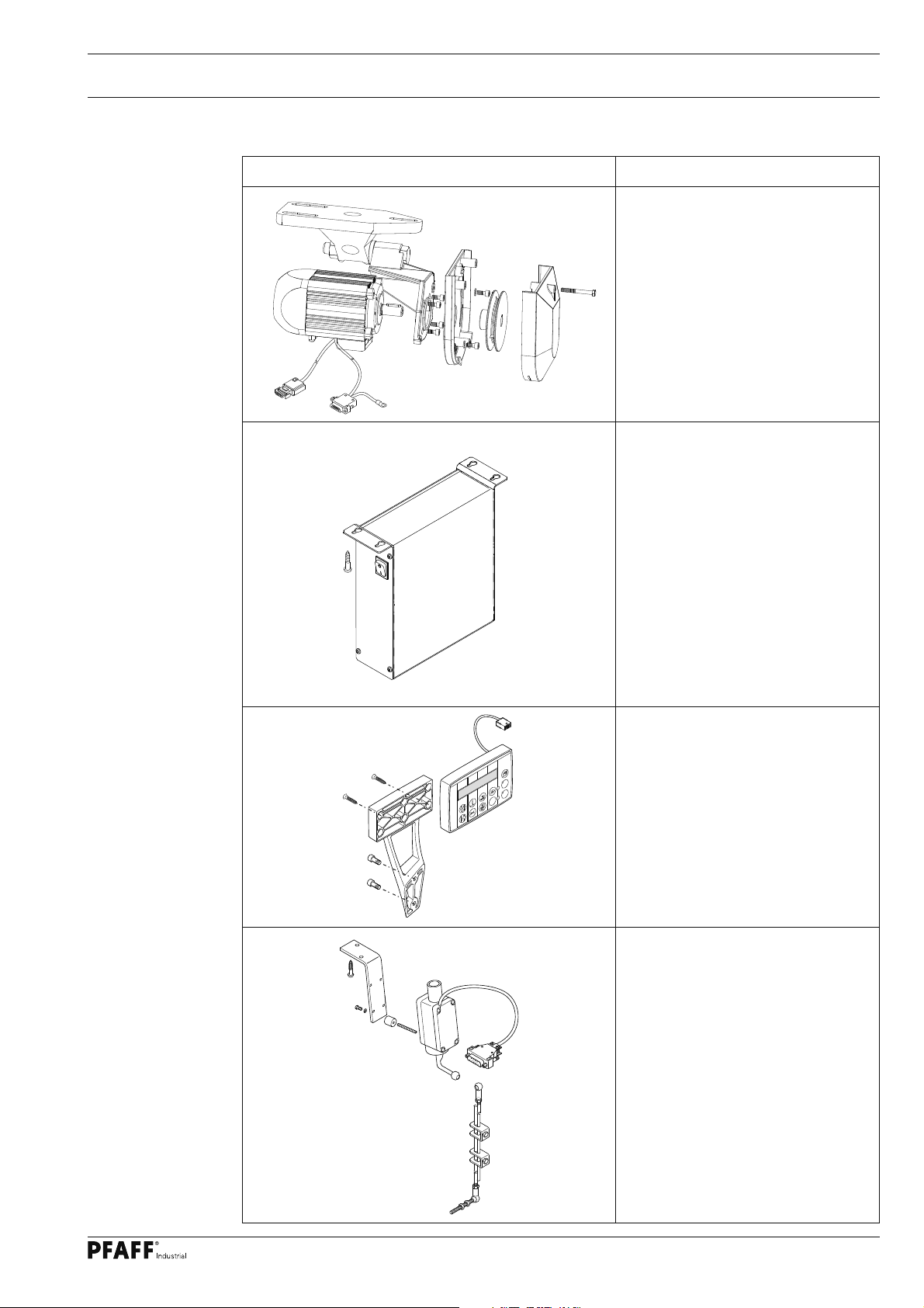
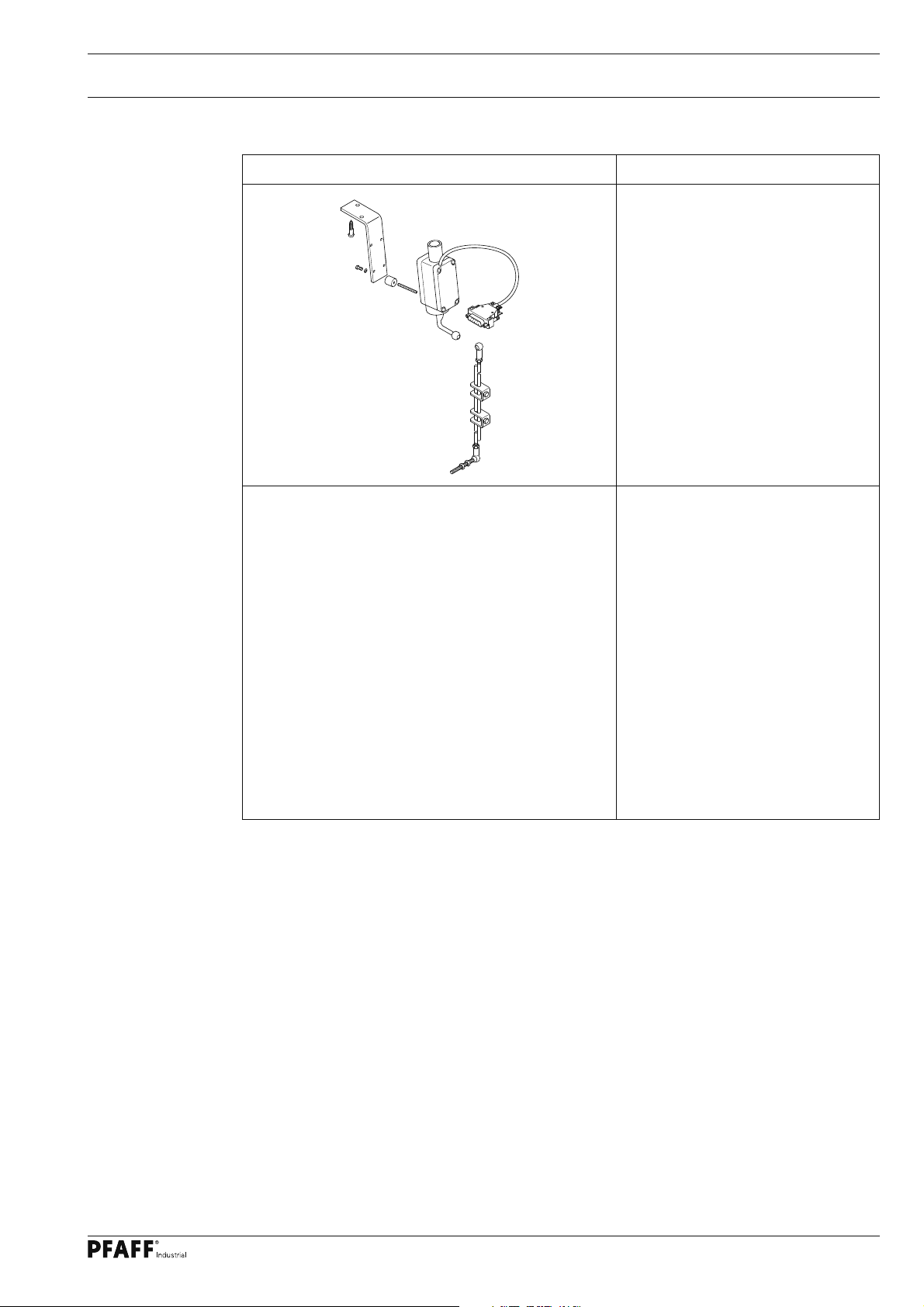
2.02 Accessories for the sewing machine drive with PicoDrive P45 PD2-L
Control package PicoDrive P45 PD2-L
Description
Motor mounting with motor and
fastening screws
Control box with fastening
screws
A
B CD
F1
TE
+
PM
-
Control panel bracket with control
panel and fastening screws
Speed control unit with holder
and fastening screws, and
connecting rod to the pedal
7
Page 8
Scope of delivery
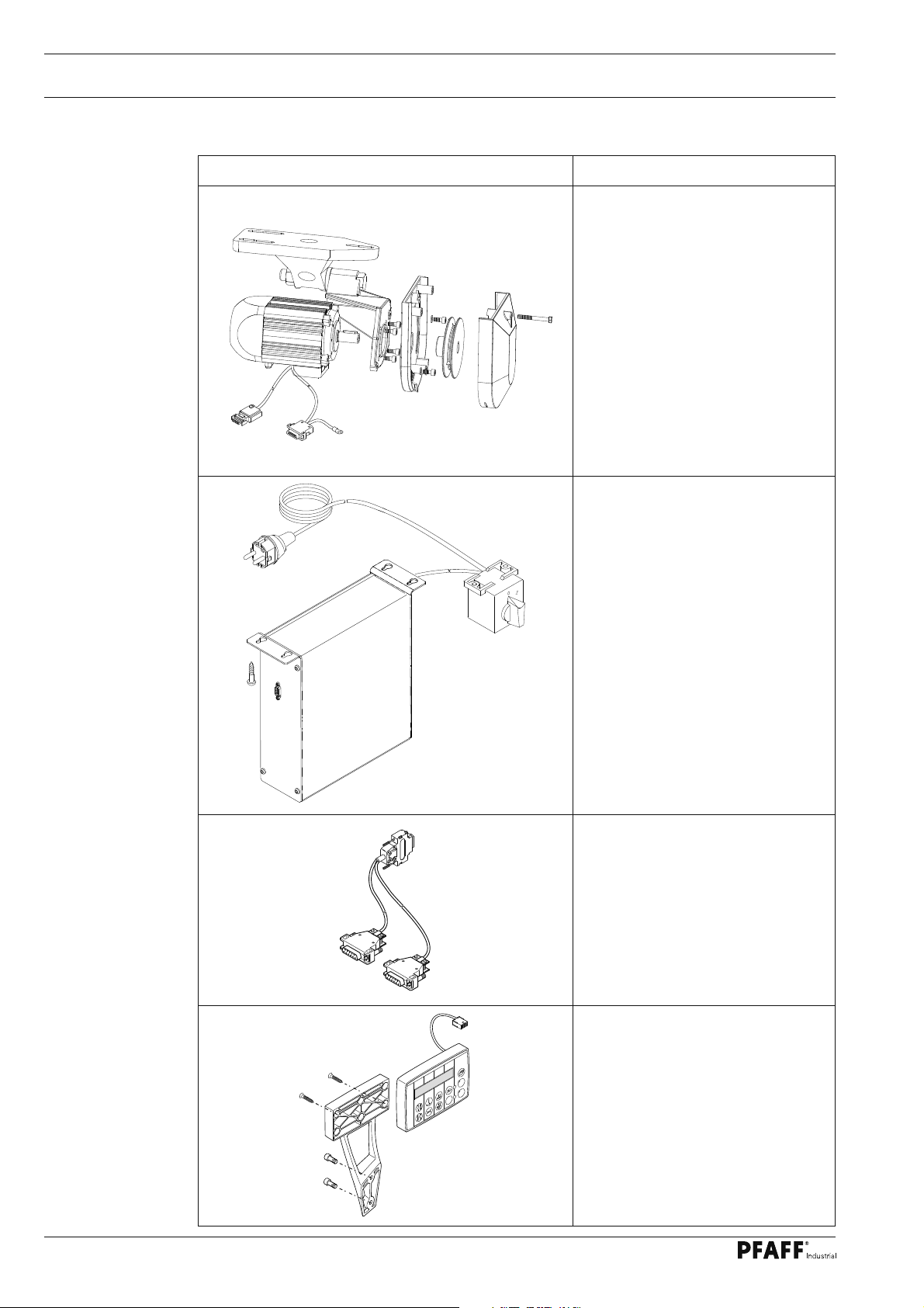
2.03 Accessories for the sewing machine drive with EcoDrive P74 ED-L
Control package EcoDrive P74 ED-L
Description
Motor mounting with motor and
fastening screws
A
B CD
F1
Control box with switch,
fastening screws and cable
Adapter cable for synchronizer
TE
+
PM
-
Control panel bracket with control
panel and fastening screws
8
Page 9
Scope of delivery
Control package EcoDrive P74 ED-L
Description
Speed control unit with holder
and fastening screws, and
connecting rod to the pedall
9
Page 10
Stand and table top
3 Stand and table top
3
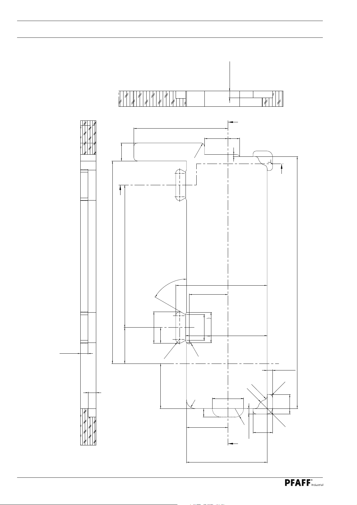
.01 Table top cutout
3
.01.01 On machines with 350 mm clearance width
B-B
240,5
46
- 0,5
B
(4x)
R 9
AA
60
-0,5 (2x)
17, 5
30
5
-0,5
B
20
517,5
92 364
(4x)
60°
- 0,5
- 0,4 (2x)
(2x)
80
40
(4x)
R 1 0
115
(4x)
R 2 2
R 9
(2x)
66
22
+0,4 (2x)
233,5
(2x)
99
(2x)
77,3
80
106
+0,4 (2x)
208
(4x)
R 9
(2x)
R 2 3
R 2 2
+0,4 (2x)
14
(4x)
R8
- 0,5
50
(2x)
R 1 5
+0,4 (2x)
50
644
+0,4 (2x)
14
+0,4 (2x)
A-A
18,7-0,5
0
906-4001-151
Vers. 08.04.08
10
206
+0,4
Page 11
Stand and table top
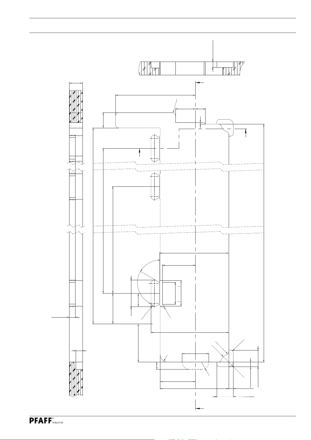
3.01.02 On machines with 700 mm clearance width
B-B
40
240,5
(4x)
R9
60
46
B
(2x)
0
17,5 - 0,5
A
30
5
B
0
906-4001-161
Vers. 24.02.11
A-A
401
719
872,5
(3x)
208 0
+0,4
(3x)
99
(3x)
(3x)
(6x)
40
115
60°
(6x)
R10
22
92
18,7 - 0,5
20
(3x)
0
80 -0,4
(3x)
77,3
66
(6x)
R9
(3x)
233,5 0
+0,4
R9
R8
(4x)
(2x)
R15
+0,4
(2x)
(2x)
(4x)
R22
106
+0,4
80
206 0
A
(2x)
R23
R22
+0,40
+0,4
(2x)
14 0
14 0
999
(2x)
+0,4
50 0
50 0
11
Page 12
Stand and table top
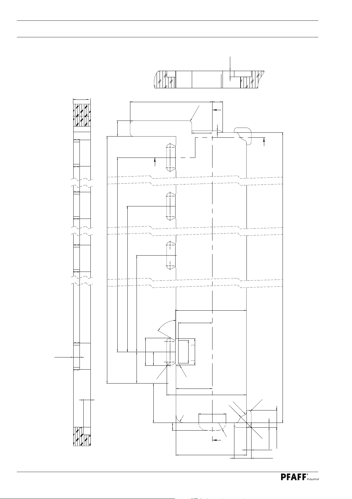
3.01.03 On machines with 1000 mm clearance width
0
17,5 - 0,5
B-B
A-A
50
46
240,5
R9
(4x)
30
A
5
60
B
B
35092
701
1019
1172,5
1299
906-4001-163
Vers. 21.01.13
12
(4x)
208 0
+ 0,4
(8x)
60°
18,7 - 0,5
0
20
(4x)
(4x)
40
0
80 - 0,4
(8x)
R10
115
R22
22
(8x)
R9
(4x)
66
(4x)
77,3
(4x)
+ 0,4
106
(4x)
+ 0,4
206 0
99
233,5 0
R9
R8
(4x)
(2x)
(2x)
R15
(2x)
(2x)
(2x)
+ 0,4
+ 0,4
50 0
14 0
14 0
+ 0,40
50 0
+ 0,4
(4x)
80
(2x)
R 23
R22
A
Page 13

Stand and table top
3.02 Assembly drawing for the table
3
.02.01 On machines with 350 mm clearance width
90
31
285
8087
70
0/1
260
906-3750-010/895
Stand position
156
AB 321 + PF 321
Controlbox
47
80
15
35
165
595,5
562,5
322,5
121,5
= Drillholes for fastening the motor
(Screwed inserts M8 x 30 )
= Hole for the sewing head support
= Öl pan
= Holes for main switch (P45 PD + P74 ED)
= Braeket for drawer
20,8
370
44
136
131
35
190
Speedcontrolunit
AB 321 + PF 321
±0,5
70
Ø14
135
±0,3
±0,3
128
128
283
512
47,5
P45 / P74
Speedcontrolunit
250
P45 / P74
Controlbox
View:
Underside table top
13
Page 14

Stand and table top
3.02.02 ON machines with 700 mm clearance width
90
31
8087
70
906-3750-000/895
Stand position
156
285
0/1
135
±0,3
±0,3
Ø14
35
±0,5
70
128
128
283
35
44
136
131
190
165
862
14
106
= Drillholes for fastening the motor
(Screwed inserts M8 x 30 )
= Hole for the sewing head support
= Holes for main switch (P45 PD + P74 ED)
= Braeket for drawer
NM
115
P45 / P74
Speedcontrolunit
Controlbox P45 / P74
View:
Underside table top
Page 15

Stand and table top
3.02.03 On machines with 1000 mm clearance width
90
31
8087
70
Stand position
156
285
0/1
135
±0,3
±0,3
Ø14
35
±0,5
70
128
128
283
35
44
136
131
190
165
1162
Controlbox P45 / P74
= Drillholes for fastening the motor
(Screwed inserts M8 x 30 )
= Hole for the sewing head support
= Holes for main switch (P45 PD + P74 ED)
= Braeket for drawer
= Drillholes for fastening the support angle
(Screwed inserts M8 x 30 )
265
±0,2
30
30
±0,2
535
115
P45 / P74
Speedcontrolunit
View:
Underside table top
Support angle
91-502 559-71/895
±0,2
30
30
NM
106
15
Page 16

Stand and table top
3.03 Assembling the stand and table top
● Assemble the stand and table top as shown in the following illustration.
● The assembly instructions in Section 3.02 must be followed.
Clearance width 1000 mm
170
kg
Clearance width 700 mm
150
kg
Clearance width 350 mm
Depending on the design, stand and table top must be confi gured f
following minimum weight:
4,2x13 (8x)
M8x16 (4x)
4,2x13 (6x)
= Given the considerable
weight of the machine, do
not operate with out support
4,2x13 (4x)
91-502 559-71/895!
or the
Fig. 3- 03
100
kg
3x20 (6x)
6x40 (4x)
4x30 (4x)
M10x20 (4x)
16
Page 17

Stand and table top
3.05 Adjusting the table-top height
1
1
2
Fig. 3 - 04
● Loosen screw 1.
● Adjust the table tap to the required working height by increasing or reducing the height
of the stand and then level the table-top horizontally.
To avoid the stand tilting, adjust it evenly on both sides.
● To guarantee that the stand is standing securely, it must be positioned securely on the
ground with all four legs.
● The height can be adjusted with screw 2.
17
Page 18

Sewing machine drive
4 Assembling the sewing machine drive
4
.01 Assembling the motor
4
.01.01 P45 PD2-L and P74 ED-L
1
2
Fig. 4 - 01
● Assemble motor mounting 1, motor 2, belt guard support 3 and belt pulley 4 as shown in
Fig. 4-01.
4.01.02 AB 321 and PF 321
● Mount the motor bracket, motor, belt guad bracket and pulley in accordance with the in-
structions in the instruction manual for the drive.
3
4
18
Page 19

Sewing machine drive
4.02 Assembling the motor, speedcontrolunit and controlbox
4
.02.01 P45 PD2-L and P74 ED-L
2
6x30 (2x)
1
M8x30 (3x)
M8x30 (3x)
Fig. 4 - 02
6x30 (4x)
6x30 (2x)
6x30 (2x)
4
5
7
3
6
7
● Fasten the motor mounting 1 with motor to the screwed inserts 2 of the table top with
three hexagon bolts M8 x 30.
● Fit the control box 3 to the table top with four screws 6x30.
● Attach the mains switch 4 to the table top with two screws 6x30.
● Screw the mains cable of the control box 3 to the table top with a mains lead cleat.
● Assemble the speed control unit 4 and attach it to the table top with two screws 6x30.
● Mount the pedal on the stand’s cross-bar, aligning the middle of the pedal with the cen-
tre of the needle.
● Fit connection rod 5 to speed control unit 4 and to the pedal.
● The slant of the pedal can be adjusted after loosening screw 6 (slant angle approx. 10°).
19
Page 20

Sewing machine drive
4.02.02 AB 321 and PF 321
2
6x30 (4x)
1
M8x30 (3x)
6x30 (2x)
4
3
6
5
6
Fig. 4 - 03
● Fasten the motor mounting 1 with motor to the screwed inserts 2 of the table top with
three hexagon bolts M8 x 30.
● Fit the control box 3 to the table top with four screws 6x30.
● Screw the mains cable of the control box 3 to the table top with a mains lead cleat.
● Assemble the speed control unit 4 and attach it to the table top with two screws 6x30.
20
● Mount the pedal on the stand’s cross-bar, aligning the middle of the pedal with the cen-
tre of the needle.
● Fit connection rod 5 to speed control unit 4 and to the pedal.
● The slant of the pedal can be adjusted after loosening screw 6 (slant angle approx. 10°).
Page 21

LED-Lamp
5 LED-Lamp (optional)
5.01 Assembling the LED lamp
2
5
4
1
Fig. 5 - 01
● Unscrew the head and arm cover.
3
1
● Remove the complete voltage mounting plate.
● Assemble the LED lamps 1 as shown in Fig. 5-01.
● Install cable 2 in the recess of the machine arm and lead plug 3 down through the
machine.
● Secure cable 2 with clamps 4 and 5 and the corresponding available screw.
● Reattach the voltage mounting plate and head and arm cover.
21
Page 22

LED-Lamp
5.02 Fitting the transformer to the LED lamp
4x20 (4x)
Fig. 5 - 02
● Attach transformer 1 to the table top with four screws 4 x 20.
● Screw the power line with clamps and main leads cleat to the table top.
● Connect the cable to the LED lamp with a connector.
22
Page 23

Installation
6 Installation
6
.01 Setting the sewing machine into the stand
1
1
Fig. 6 - 01
● Attach each of the hinges 1 to the sewing head with two screws M6 x 16.
● On the PFAFF 2542 and 2545/46 attach tilt lock 2 with a M5 x 6 screw
(on the PFAFF 2231 + 2235 the tilt lock is already attached)
● Set the sewing machine into the table top.
2
23
Page 24

Installation
.02 Fitting the V-belt and assembling the bottom belt guard
6
6
.02.01 P45 PD2-L and P74 ED-L
6
7
1
2
3
4
5
3
Fig. 6 - 02
● Fit the V-belt to the balance wheel and the motor pulley.
● Loosen nut 1 and apply tension to the V-belt by turning motor mounting 2.
● Tighten nut 1.
● Loosen screws 3 and adjust belt guard bracket 4 so that the driver pulley and V-belt are
running freely.
● Tighten screws 3 and fasten belt guard 5 with screw 6 (nut 7).
.02.02 AB 321 and PF 321
6
● Fit the V-belt to the balance wheel and the motor pulley.
● The V belt is tensioned by turning the motor bracket.
● Mount the lower belt guard in accordance with the instruction manual for the drive.
24
Page 25

Installation
6.03 Assembling the thread guide and take-up lever guard
3
2
3
4
5
6
10
8
7
1
9
11
Fig. 6 - 03
● Remove face plate 1 and arm cover 2 (screws 3).
● Adjust thread guide 4 (screw 5) as shown in Fig. 6 - 03.
● Screw thread guide 6 into threaded hole 7 and fi t counter nut 8 from below.
● Fasten take-up lever guard 9 to the arm cover 2 with screws 10 (M4x10) and nuts 11 as
shown in Fig. 6 - 03.
Leave face plate and arm cover unscrewed for the next assembly steps.
25
Page 26

Installation
6.04 Assembling the top V-belt guard and sewing head support
2
2
Fig. 6 - 04
● Attach guard belt 1 with screws 2.
● Insert sewing head support 3 into the hole in the table top.
Do not operate the machine with support 3! Danger from top-heavy
sewing head! Machine cannot fall over when tilted backwards!
2
3
1
26
Page 27

Installation
6.05 Mounting the control panel
2
3
4
1
6
5
Fig. 6 - 05
● Attach the control panel bracket 1 with two screws M5 x 12 to the machine.
● Attach spacer plate 2 with one screw M5 x 12 to the control panel 3 (with motor
AB 321 and PF 321 only)
● At
tach control panel 3 to bracket with two screws 5 x 10.
● Lead the control panel cable through hole
● Connect the control panel plug with the connector provided for the control panel in the
arm of the machine.
4 in the case.
● Reattach face plate 5 and arm cover 6.
27
Page 28

Installation
6.06 Connecting the plug-in connections and earth cables
A
M6x16
Fig. 6 - 06
● Connect all connectors to the control unit 1 as shown in the block diagram
(see chapter 6.07).
● The following ground cables must be attached in order to discharge static electricity.
● Securely attach the ground cables for the machine to ground point A.
● Connect the ground point on the motor base and on the control unit by way of a ground
cable to ground point A.
● For control unit P45 PD-2-L and P74 ED-L, connect the ground cable to the master switch
and ground point A.
● For control unit P45 PD-2-L and P74 ED-L screw-connect the ground cable from plug X1 to
the ground point of the control box.
28
Page 29

Installation
6.07 Block diagram
6
.07.01 PFAFF 2231 and 2235 with PicoDrive P45 PD2-L
Synchronizer PD 6
2231
2235
Optional
Light
barrier
Speed control unit
Control unit QA40 PD
A1
Ministop drive unit
(long) with incremental
transducer
LED
LED
power
supply
Netzteil
unit
PC
for
software
download
Q1; HQ1
Power switch
FSL = Thread tension release
FK = Thread clamp
PFA = Automatic presser foot lift
ML = Machine running signal
-900 = Thread trimmer
VR = Backtacking device
KS = Knee switch for automatic presser foot lift
Mains plug
29
Page 30

Installation
6.07.02 PFAFF 2235, 2542 and 2545/46 with EcoDrive P74 ED-L
Synchronizer PD 6
Optional
Light
barrier
A 20
A20
Y3, Y4, Y5, Y6, Y9
Y8, Y14, Y1X, R1
XA20
Option
B30
XS27
XS29
2235
2542
2545
2546
S26
Ministop drive
unit (long) with
incremental
transducer
BDF - PICO TOP
LED
power
supply
unit
A2
PC
X7
Control unit P74 ED
A1
X3
S1.1
X5
KS
X1
X2
X2.1
X2
Q1; HQ1
power switch
Mains plug
X2.2
X2.2
Adapter
X4
for
software
download
X0
30
Page 31

Installation
6.07.03 PFAFF 2545/46 BASIC with PicoDrive P45 PD2-L
Synchronizer PD 6
2545 BASIC
2546 BASIC
BDF - PICO TOP
BDF - PICO TOP
H1
Control unit QA40 PD
A1
Ministop drive
unit (long) with
incremental
transducer
LED
power
supply
unit
PC
PC
for
software
download
Q1; HQ1
power switch
Mains plug
31
Page 32

Installation
6.07.04 PFAFF 2235 with AB 321
Synchronizer PD 6
PD 6
FK
ML
FSL
2235
-900 VR
PFA
LS
(Option)
BDF
SWG
FSL = Thread tension release
BDF = Control panel
FK = Thread clamp
PFA = Automatic presser foot lift
ML = Machine running signal
-900 = Thread trimmer
VR = Backtacking device
SWG = Speedcontrolunit
KS = Knee switch
X 5
ST 2
KS
B 2B 80
Mains plug
B 41
Adapter
1113229
B 18
B 776
USB
for software
download
32
Page 33

Installation
6.07.05 PFAFF 2235, 2542 and PFAFF 2545/46 with PF 321
Synchronizer PD 6
PD 6
2235
UFW
(Option)
Y3, Y4, Y5, Y6,
Y8, Y14, Y1X, R1
2542
2545
2546
LS
(Option)
BDF
SWG
BDF = Control panel
UWF = Lower thraed monitor
SWG = Speedcontrolunit
KS =
Knee switch
X 5
ST 2
KS
Adapter
1113229
B 41
B 2B 80
B 18
B 776
USB
for Software
download
Mains plug
33
Page 34

Installation
6
.08 Mounting / connecting the maintenance unit
1
Fig.6 - 08
● Attach maintenance unit 1 to the stand with two screws M6 x 25.
● Connect the maintenance unit to the machine’s pneumatic tube.
To ensure the perfect functioning of all pneumatic devices, there must be a supply system pressure of between 8 and 10 bar.
The operating pressure is 6 bar (also see Chapter 9 Care and Maintenance of
the instruction manual).
34
Page 35

Commissioning
7 Commissioning
Before commissioning the machine, it must be thoroughly cleaned and then
oiled., see chapter 9 Care and maintenance in the instruction manual.
● Check the machine, particularly its electrical wiring and pneumatic tube
connections, for any damage.
● Have skilled personnel check if the machine can be operated with the available mains vol-
tage.
Do not operate the machine if there is any discrepancy.
The machine may only be connected to an earthed socket!
● In the case of machines with PicoDrive and P45 PD2-L control unit, have specialists
check the basic position of the machine drive before commissioning the machine (see
Chapter 7.02 Basic position of the machine drive).
7.01 Switching the machine on/off
● Switch the machine on (see Chapter 7.01, On/off switch in the instruction manual).
35
Page 36

Commissioning
7.02 Machine drive home position
7
.02.01 Only on machines with drive P45 PD2-L
● Switch on the machine.
● When the machine is commissioned, "Pulley" appears on the display.
● Call up the parameter input by pressing the scroll key.
● Press the TE key to switch the function keys to input function (LED in the TE key is
● Press the corresponding +/- keys to select parameter "798" and select the service level
● Select parameter "800" by pressing the corresponding +/- keys.
● Check whether the value is set at "1" (balance wheel turns towards operator) and alter if
● Press the scroll key until "Pulley" appears on the display.
illuminated).
C, see chapter Selecting the User Level in the separate instruction manual for the control
panel.
necessary.
● If the pedal is operated, the control unit carries out a teach-in operation.
● The machine runs at low speed until the teach-in operation is completed.
● This operation cannot be interrupted.
● After the teach-in operation, the "Pulley" disappears from the screen - display returns to
standard.
● Select parameter "700" by pressing the +/- keys.
● Sew one stitch by operating the pedal.
● Turn the balance wheel in the direction of rotation until the needle point, descending
from above, is fl ush with the top edge of the needle plate.
● Conclude the adjustment of the sewing motor by pressing the scroll key.
7.02.02 Only on machines with drive P74 ED-L
On machines with EcoDrive P74 ED-L it is not necessary to check the basic
position of the machine drive unit.
These machines are equipped with an automatic sewing head recognition
function.
36
Page 37

Commissioning
7.02.03 With model PFAFF 2235 and drive AB 321
● Press button "P" on the control panel, while simultaneously switching the machine on.
● Enter code 3112 via the numbered keys and confi rm by pressing "E".
● Enter parameter 290 via the numbered keys and confi rm by pressing "E".
● Select mode 42 by pressing the +/- buttons.
● Press "P" twice to quit the input level.
● The new values are taken over when sewing is started, and these are maintained even
after the machine is switched off.
7.02.04 With models PFAFF 2235, 2542, 2545 / 46 and drive PF 321
● Press button "P" on the control panel, while simultaneously switching the machine on.
● Enter code 3112 via the numbered keys and confi rm by pressing "E".
● Enter parameter 290 via the numbered keys and confi rm by pressing "E".
● Press the +/- buttons for mode 00 for model 2235, and mode 01 for models 2542,
2545 / 46.
● Press "P" twice to quit the input level.
● The new values are taken over when sewing is started, and these are maintained even
after the machine is switched off.
37
Page 38

PFAFF Industriesysteme
und Maschinen AG
Hans-Geiger-Str. 12 - IG Nord
D-67661 Kaiserslautern
Phone: +49 - 6301 3205 - 0
Fax: +49 - 6301 3205 1386
E-mail: info@pfaff-industrial.com
Printed in Germany
© PFAFF Industriesysteme und Maschinen AG 2009, PFAFF is the exclusive trademark of VSM Group AB.PFAFF Industriesysteme und Maschinen AG is an authorized licensee of the PFAFF trademark.
 Loading...