

Page 1
MAUSER
SPEZIAL
Serie
40
Adjustment
instructions
Pfaff
Industriemaschinen
GmbH
675
West-Germany
Kaisersiautern
Page 2
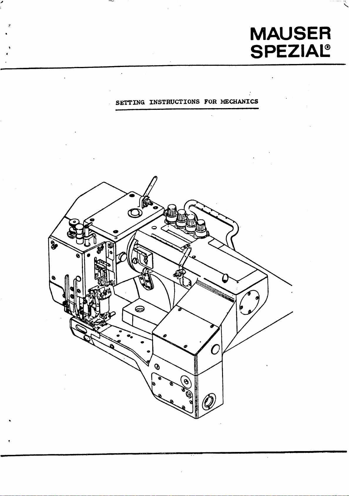
MAUSER
SPEZiAl^
SETTING
INSTRUCTIONS
FOR
MECHANICS
Page 3
Supplement
for
machines
to
the
with
service
low
needle-bar
manual
for
link
Mauser
Cl,
^0,
stroke
1«
3«
4.
5*
20.4
Needle
Looper
Needle
Looper
Elliptical
mm)
bar
height:
clearance:
rise:
avoiding
movement:
motion:
needle
stroke
Preliminary
Clearance
needle
fourth
From
of
2.^
1.8
Forwards:
from
needle:
looper
first
nun
to
first
29*5
between
plate
needle:
needle:
to
middle
2
mm,
mm,
adjustment:
and
9.3
tip
to
depending
needle
0.15
looper
top
point
middle
of
to
mm
mm
first
fourth
surface
of
mm
on
of
the
needle.
fabric.
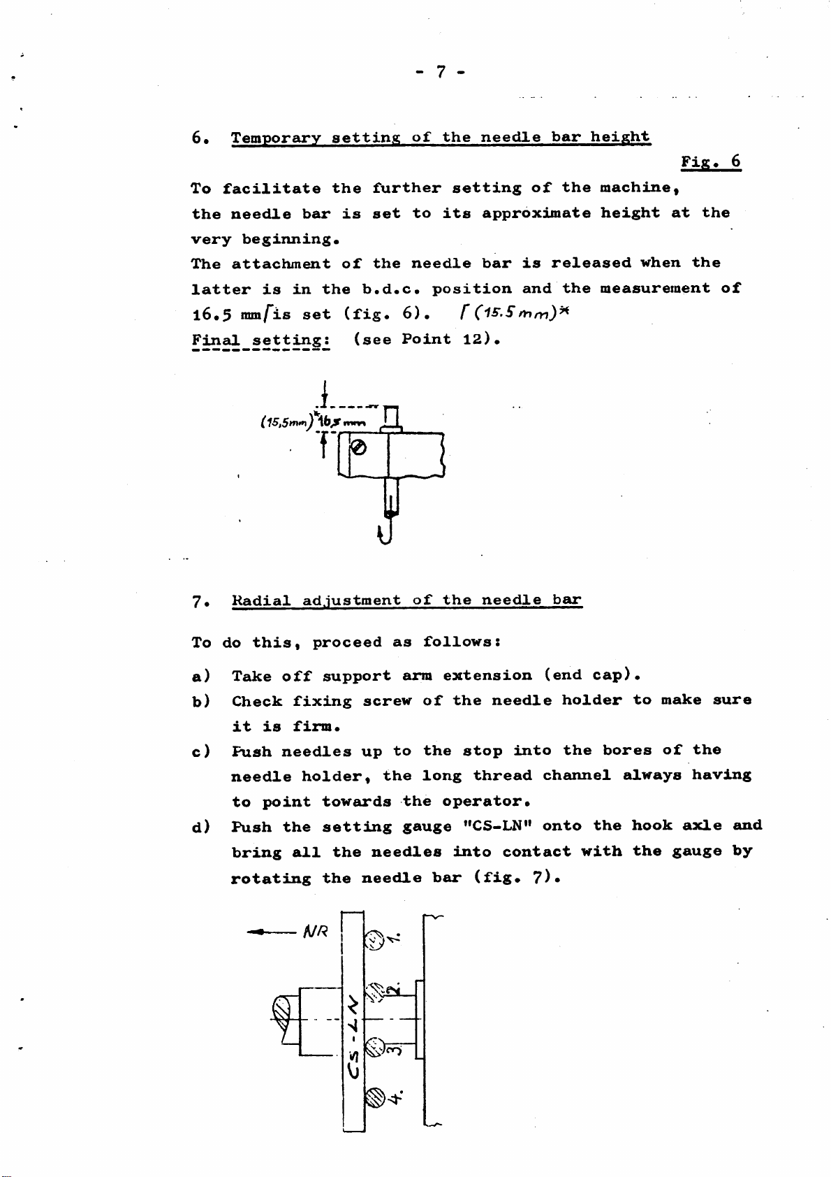
6.
Check:
1.
2.
The
up
eyeaof
When
third
of
0.3
the
looper
at
the
the
ram
looper.
a
the
and
third
below
point
position
fourth
looper
fourth
is
needle
the
should
1 mm
needle.
between
needle
shoulde
underside
pick
above
the
the
the
tip
be
of
Page 4
- 1 -
for
MAUSER
(for
machines
These
The
basic
Series
sequence
Note
The
this
s
letters
manual,
correspond
ed
to
SPECIAL
instructions
setting
is
described
o
or
to
simplify
S12TTING
with
numbers
which
the
the
INSTRUCTIONS
Series
2Se5
mm
(29,5
are
mainly
of
MAUSER LOCK
in
this
used
indicate
spare
explanationso
parts
kO
needle
mm)»
Down
intended
manual
in
the
the
numbers
Arm
stroke)
Machines
in
illustrations
machine
Sewinja;
for
mechanics«
of
a
practical
components,
but
are
Machines
the
kO
operation
accompanying
merely
do
intend
not
In
addition,
illustrate
the
meanings
NR
SettdLng
For
direction
gauges
the
the
interaction
of
these
required;
of
illustrations
symbols
=
direction
=
direction
reversing
pendulum
(
direction
rotating
sewing
of
horizontal
hook
contain
the
are
of
of
point
movement
of
parts
=
"CS-LG"
symbols
individual
as
followss
sewing
feed
or
rotation
indicated
of
indicated
vertical
gauge
which
movements;
by
arrow
a
feed
or
or
by
)
moveoient
arrow
of
For
direction
Needle
for
machines
hook
with
of
needle
spacer
29.5mmneedle
gauge
bar
bar
^08
stroke
=
"CS-LN"
mm
mm)*
gauge
Page 5
- 2 -
1.
2*
3«
4.
5*
6.
7»
8»
9*
Tlie
necessary
The
needle
Needle
check
Temporary
hook
Temporary
movement.
Temporary
Radial
Setting
movement
adjustment
Setting
CONTENTS
needle
arrangement
synchronization
setting
setting
the
the
stroke
hook
of
of
of
inclination
TABLE
system
feed
needle
needle
ot
the
of
and
bar
bar
hook
needle
transverse
height
deflection
vritlx
and
longitudinal
hook
the
"CS-LG" gauge
movement
10*
11.
12.
13*
l4.
15*
16.
17.
l8•
19*
20.
Setting
Final
hook
Final
Final
synchronization
movement
setting
setting
Alignment
Final
movement
setting
Stitch
Setting
Setting
Setting
Fitting
the
of
length
the
the
the
and
hook
of
needle
of
the
main
of
"lifting
and
needle
take—up
looper
setting
spacing
of
needle
bar
hook
and
differential
differential
stop
lever
thread
of
the
and
height
deflection
and
lowering"
regulation
movement
puller
trimmer
longitudinal
movement
feeder
feeder
blades
Page 6
- 3 -
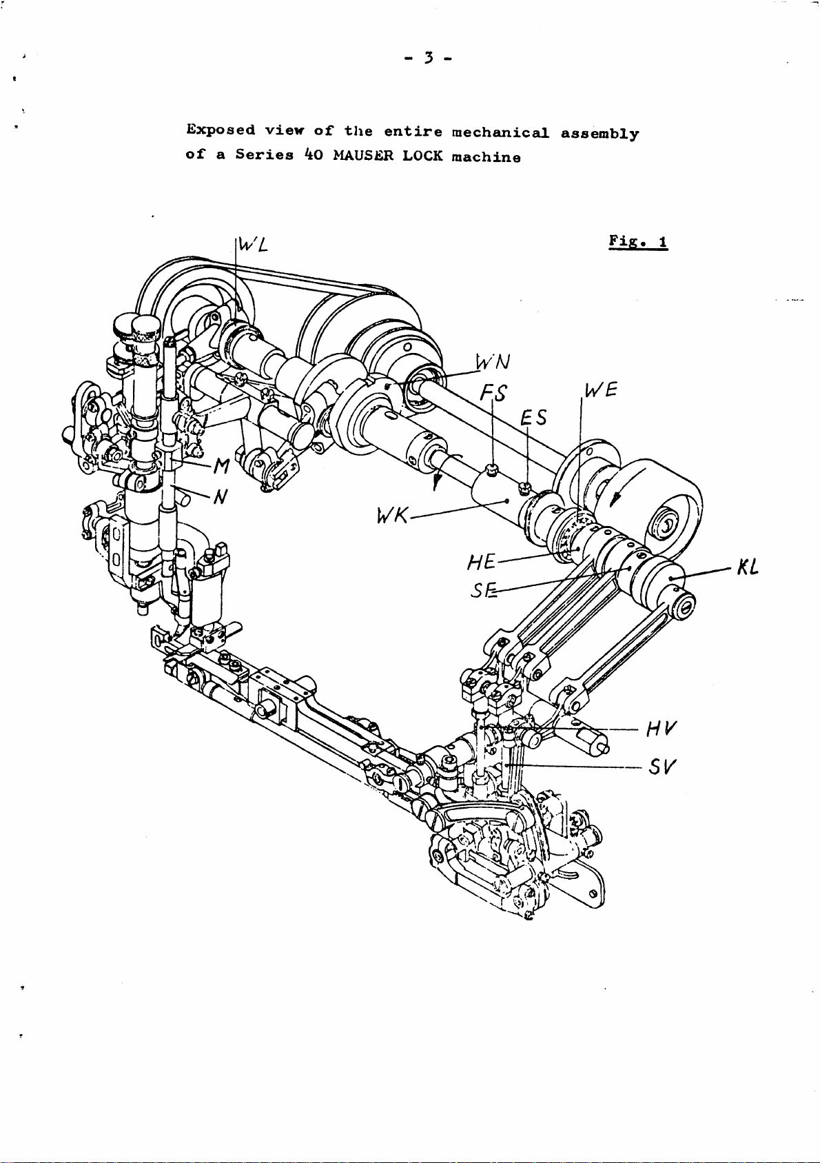
Lxposed
of
a
Series
view
of
the
40
MAUSiiR LOCK
entire
mechanicaJL
machine
assembly
Fig
Page 7
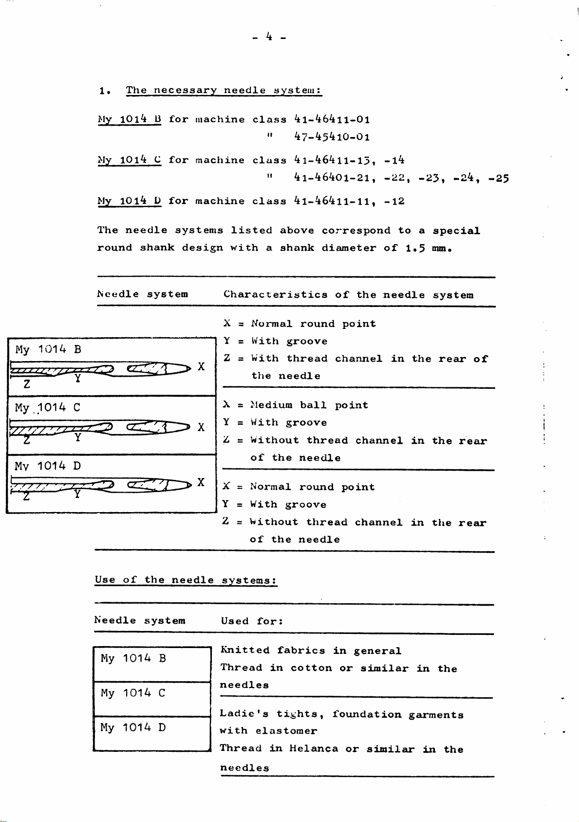
1•
My
My
My
The
The
10i3
1014
10l4
needle
necessary
for
C
for
D
for
systems
needle
machine
machine
machine
listed
- 4 -
system:
class
"
class
"
class
4l-464ll-01
47-45410-01
4l-464ll-l5,
4i-46401-21,
4l-464ll-ll,
above
correspond
-l4
-22,
-12
to
-23,
a
-24,
special
-25
My
1014
My.1014
iZ^ZZZZ^
Mv
1014
B
C
Y
D
round
Needle
shank
system
design
with
a
Characteristics
X =
Normal
Y =
Z =
X =
Y =
Z =
X =
Y =
Z =
With
With
the
Medium
With
Without
of
the
Normal
With
Without
needle
shank
groove
thread
groove
groove
round
ball
thread
needle
round
thread
diameter
of
point
channel
point
point
the
channel
channel
of
needle
in
1.5
the
in
in
nun.
system
rear
the
the
of
rear
rear
of
the
needle
Use
of
the
Needle
My
My
My
1
1014
1014
1014
needle
system
B
C
D
systems;
Used
Knitted
Thread
needles
Ladie's
with
Thread
needles
for:
fabrics
in
tights,
elastomer
in
cotton
Helanca
in
general
or
similar
foundation
or
simileu*
in
the
garments
in
the
Page 8

3•
Needle
- 5 -
check
Only
To
avoid
straight
surface
k•
The
new
needles
all
running
(fig.
Temporary
longitudinal
mechanism
must
risks,
before
3).
synchronization
hook
for
the
the
be
used
needles
use
movement
feeder
by
for
must
rolling
of
and
setting
be
checked
them
needle
longitudinal
up
and
on
the
hook
machine.
for
a
flat
move
ment
by
the
"WK"
The
situated
tlie
needle
(fig.
crank
movement)
l)
.
Tlie
synchronization
movement
The
basic
unadjusted
chronization
hook
movement«
drive
CcUi
adjustment
shaft
drive
l).
"KL"
is
firmly
therefore
machine
of
in
(for
the
the
"WE",
shaft
the
connected
of
starts
needle
suj)port
"WN"
the
only
of
a,
which
drive
first
arm
is
by
means
of
to
needle
be
set
for
exsimple,
movement
of
adjustably
the
the
and
at
with
the
machine
of
the
longitudinal
drive
longitudinal
the
shaft
completely
the
temporary
\>rita
the
connected
shaft
shaft
longitudinal
Fig.
is
controlled
coupling
hook
"WE"
hook
coupling
syn
4
to
(fig.
I
Page 9
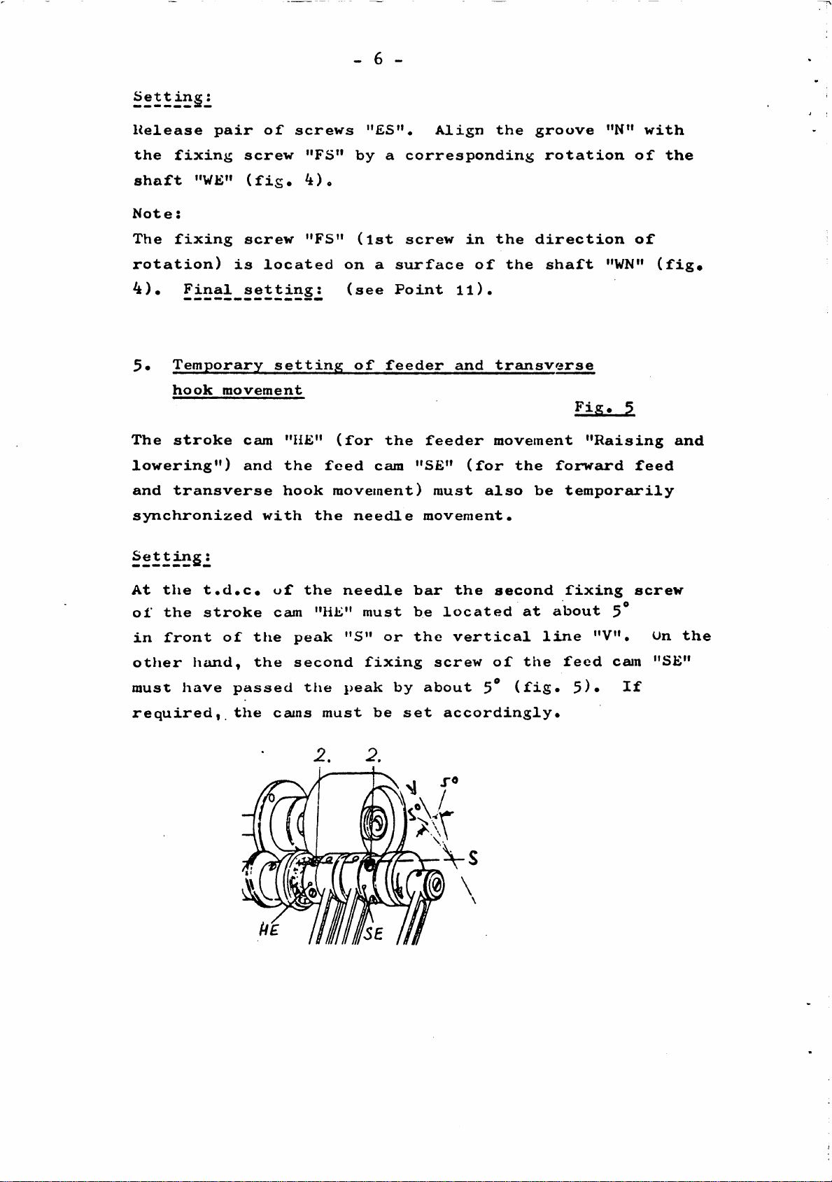
Sett
- 6 -
ing:
Helease
the
fixing
shaft
Note:
The
"WE"
fixing
rotation)
4).
5*
The
Final
Temporary
hook
stroke
lowering")
and
transverse
synchronized
pair
screw
screw
is
setting:
movement
cam
and
of
(fig.
located
with
screws
setting
"HE"
the
hook
"FS"
^)o
"FS"
on
(for
feed
movement)
the
"£S"«
by
(1st
(see
of
needle
a
corresponding
screw
a
surface
Point
feeder
the
cam
"SE"
Align
in
of
ll).
and
feeder
(for
must
movement.
the
the
the
transverse
movement
the
also
be
groove
rotation
direction
shaft
£i£.
forward
temporarily
"N"
"WN"
"Raising
with
of
of
feed
the
(fig*
and
Setting:
At
the
of
the
in
front
otJier
must
required,
t.d.c.
stroke
hcUid,
have
of
passed
the
the
the
uf
cam
peak
second
cams
the
"HE"
tlie
must
needle
must
"S"
fixing
peak
be
s
or
by
bar
be
the
about
set
the
located
vertical
screw
5^
accordingly.
second
of
(fig.
at
the
about
line
fixing
feed
5)*
"V",
5*
cam
If
screw
On
"SE"
the
Page 10
6*
To
the
Temporary
facilitate
needle
bar
setting
the
is
further
set
- 7 -
of
the
to
setting
its
needle
of
approximate
bar
the
height
machine«
height
at
Fig^
6
the
very
The
latter
l6*5
Final
7•
To
beginning*
attachment
mm/"is
setting:
C
Radial
do
this,
is
in
set
15,5nvn^
adjustment
of
the
(fig*
T
proceed
the
b.d.c*
(see
needle
position
6)* f
Point
]
of
as
follows:
the
bar
12)*
needle
is
and
released
the
bar
when
measurement
the
of
a)
b)
c)
d)
Take
Check
it
is
Push
needle
to
point
Push
bring
rotating
off
fixing
firm*
needles
holder,
the
all
A//?
support
screw
up
towards
settdLng
the
the
needle
n
arm
to
the
the
gauge
needles
extension
of
the
the
stop
long
operator*
"CS-LN"
dlnto
bcur
needle
thread
contact
(fig*
into
(end
holder
channel
onto
?)•
the
cap)*
the
with
bores
always
to
hook
the
make
of
axle
gauge
sure
the
having
and
by
Page 11

8.
The
Setting
movement
hook
the
passes
stroke
around
- 8 -
of
the
the
hook
needles
deflection
in
an
elliptical
path
which
movement
(cam "ES")
movement
supplier's
(width
1,8
2.0
(fig.
;^i-longit.
inm
mm
of
for
for
8).
is
(crank
(fig.
(length
works,
the
machines
macliines
hook
brought about by
"KL")
l).
of
ellipse)
movement
the
the
with
with
and
the
V/hereas
ellipse)
deflection
must
be
Helanca
cotton
the
hook
the
longitudinal
is
movement
set
threads
threads
longitudinal
deflection
determined
of
the
to
a
value
in
the
in
the
hook
movement
hook
in
the
hook
"X"
of;
needles
needles
or
Setting^
The
stroke
on
the
upwards,
"X"
segment
the
is
set
lever
dimension
by
"SQ".
adjustment the dimension
I2l
mz
Measure
Mount
dimension
hook
?h
-Hd
holder
6 I
"X"
as
"GH"
regulating
If
"X"
decreases,
"X"
increases
follows;
temporarily
the
the
ball
onto
ball
joint
with
(fig.
the
joint
is
adjusted
downward
9).
—'
Fig.
hook
shaft
"ti"
10
"G".
At
the
the
bearing
front
distance
bush
d.c.
"D"
(fig.
position
between
lOa).
the
of
the
hook
hook
holder
shaft
"GH"
measure
and
the
Page 12

At
the
"D"
has
9-
tli0
distance
and
been
Setting
gauge
opposite
"d"
correctly
d.«c«
"d"«
provides
the
hook
- 9 -
position
The
difference
the
adjusted*
inclination
of
dimension
the
of
with
"X"
hook
the
if
the
shaft
measured
the
ball
"CS-LG"
measure
values
joint
"Q»»
Insert
the
the
the
the
10*
To
a)
pin
hook
hook
hook
Setting
do
Push
the
nut
the
of
this,
hook
the
blade
fixing
blade
the
hook
"M".
into
hook
parallel
screw
is
CS-LG
the
proceed
hook
shaft
Tighten
the
inclination
parallel
hook
as
holder
"G"*
hook
against
"BS".
spacing
follows:
the
Check
to
"GH"
Engage
clamping
lever
gauge
the
the
and
"H"
"H"
gauge
again,
gauge
the
in
screw
and
push
"CS-LG".
and
to
(fig*
^3
FU.11.
hook
"GH"
"K"
lever
and
Apply
tighten
ensure
ll)*
apply
until
"H"
"H"
onto
that
onto
the
b)
combination
hand
Turn
feed
(dead
(fig*
the
until
centre)
of
12)* H
machine
the
"H"
hook
(fig.
and
balance
has
13).
"GH"
wheel
reached
can
in
still
its
the
be
direction
initial
moved
by
of
position
Page 13

c)
The
and
distance
the
tip
fc>etween
of
the
-
10
the
hook
-
centre
represents
o£
the
the
first
hook
needle
spacing*
Tlie
hook
needle.
the
hook
(fig.
setting
When
needle
without
l4).
the
must
spacing
By
shifting
tip
This
of
the
hook
be
causing
(4,4
is
hook
passes
lightly
mm)*
gauge
the
brought
adjustiiient
tip
any
deflection
(4.8
combination
into
to
5
behind
touched
Fig.
l4
r(4,4mm)*
i)l :
mm)/
contact
incorporates
the
rear
the
by
of
is
applied
of
needles,
the
the
of
with
the
tip
needlel
"HI'
the
the
the
of
to
and
first
the
gauge
axial
first
the
(fig.
first
"Gdi",
needle.
hook,
15)*
11.
To
a)
hook
do
Lift
by
Final
this,
synchronization
movement
the
turning
proceed
needle
the
—2.0
balance
(2',
Fig.
as
follows:
bar
by
trim
1mm)*
16
of
needle
2.0
wheel
and
mm/from
(fig.
longitudinal
its
d.c.
l6).
position
Page 14
-
11
-
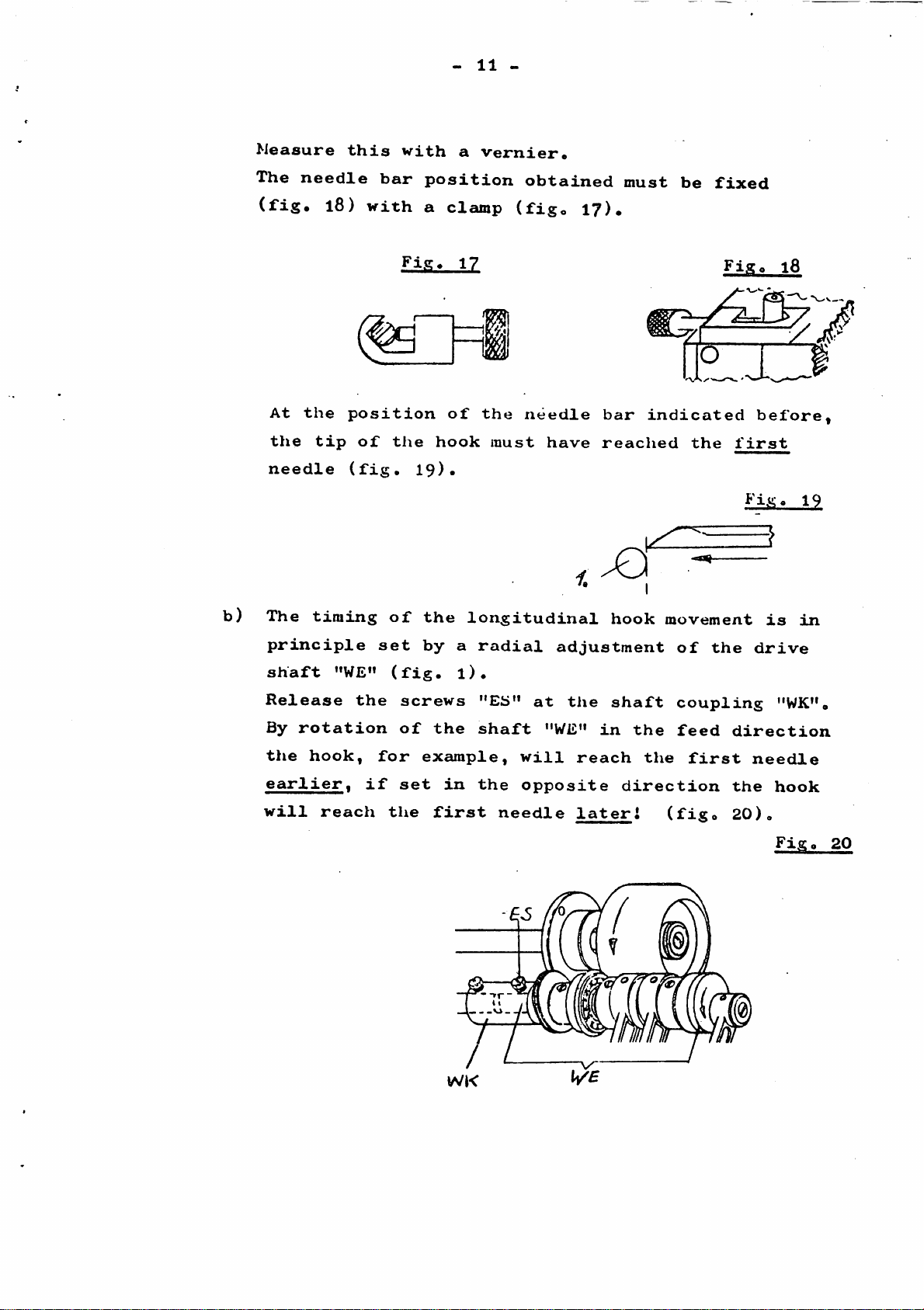
Measure
The
needle
(fig.
At
the
the
needle
18)
tip
this
bar
with
position
of
the
(fig.
with
position
a
19)-
a
clamp
of
hook
vernier.
obtained
(fig.
the
needle
must
have
17).
bar
reached
must
indicated
be
the
fixed
Fig.
3
first
18
before,
5
b)
The
timing
principle
shaft
Release
By
rotation
the
hook,
earlier,
will
"WE"
reach
the
if
of
set
(fig.
for
the
the
by
screws
of
the
example,
set
first
longitudinal
a
radial
l).
"Eb"
shaft
in
the
needle
adjustment
at
the
"WE"
will
opposite
in
reach
later!
hook
shaft
the
the
direction
movement
of
the
coupling
feed
(fig.
direction
first
the
20).
9
is
drive
"WK".
needle
hook
Fig.
in
20
WK
Page 15

-
12
-
12•
Move
needle
(fig.
needle
1*2
The
the
21).
mm
f(fig*
distance
simplify
or
comparative
Example:
Aus)^
1.5|x
the
The
releasing
Note:
The
setting
hook up
by
turning
eye
and
this,
_
needle
height
the
setting
The
the
must be
one
dimension*
of
fixing
of
the
of
the
to
the
the
balance
needle
left-hand
bar
wheel
edge
in
heigh't
of
the
distance between the upper
lower
uses
diameter
the needle bar
screws on the
needle
edge
determined
the
needle
of
0.8
bar
height
of
the
by
mm=1.2
"N"
hook
estimating#
diameter
can be
driver
must be
the
fourth
feed
edge
blade
as
a
mm
distance.
adjusted
"M"
(fig.
carried
direction
of
the
must
be
To
reference
after
l).
out
with care, so
under
The hook
needles.
5)
determines
radial
Point
•
Final
produces
position.
setting
runs
Hie
the
that
7
is
through
feed
the
direction
the
maintained!
of
the
an
cam
deflection
direction
hook
elliptical
"SE"
on
movement
of
the
of
the needle bar adjusted
hO
Fig.
a
1/
deflection
path
the drive shaft
of
hook
movement
movement
around
the
hook
"WE"
and
with
21
the
(fig.
its
n
W"®"
♦
i
~~(E)~
t!
Page 16

If
of
the
tip
the
the
hook
passes
feed
hook
deflection
cam
track
behind
"SE"
up
the
-
has
to
stroke
needles
13
the
-
been
must
correctly
reversing
be
(starting
point
Ool^mm
set,
when
from
the
(d«c»)
the
position
drift
of
hook
"A")
must
a)
(fig.
The
be
Turn
the
(fig.
Now
"GH"
22).
moment
set
the
tip
23).
measure
and
of
as
follows:
balance
of
the
the
reversal
hook
the
bearing
wheel
has
distance
bush
Fig.
of
in
reached
"d"
the
the
(fig.
2kA
hook
feed
the
=3
between
2^a).
deflection
direction
first
Fig.
the
needle
hook
stroke
until
23
holder
b)
c)
Continue
until
point
be
0.15mm
Note:
With
feeder
Check
first
the
(d.c.).
the
motion
the
needle
to
turn
hook
more
adjustment
position
has
acc.
the
shaft
Now
than
balance
"G"
measure
the
described
been
of
to
fig.
distance
set
the
has
hook
13
wheel
the
at
reached
distance
above,
the
tip
and
in
"d"
same
correct
in
the
its
"D",
(fig.
the
timel
relation
feed
front
24b).
timing
if
direction
reversing
which
of
to
necessary.
must
the
the
Page 17

To
a)
•
do
Attach
Alignment
this,
proceed
the
of
main
support
-
as
1^
and
follows:
arm
-
differential
extension
(end
feeder
cap)
and
fix
feeders*
b)
Align
*nain
bolt
c)
The
carried
screws
independently.
position
the
the
feeder*
"B"
height
needle
Position
differential
accordingly
adjustment
out
"C"
first).
project
plate
25
Relscise
on
the
The
needle
eccentric
by
(fig,
feeder
screw
(fig*
of
The
main
feeders
a
complete
25),
plate
25)*
the
and
horizontally
"A"
and
differential
bolt
feeder
should
tooth
"D"
at
fix*
turn
(release
can
the
height
to
eccentric
feeder
be
adjusted
highest
out
the
is
of
of
the
feeder
Longitudinal
the
Differential
Main
main
height
feeder
pngl'tudinal
the
main
feeder
differential
setting
fedder
feeder
ad.lustmefat
setting
of
Page 18

-
15
-
15*
The
by
At
the
of
reached
Alternatively,
needle
Note:
If
the
direction,
Final
feeder
"raising
the
the
rising
the
the
feeders
feed
correct
needle
the
descends.
feed
setting
movement
and
cam
"HE"
setting
second
plate
top
edge
the
cam "HE"
will
they
lift
will
of
the
lowering"
(fig.
of
needle
when
of
same
situation
is
adjusted
earlier.
lift
"raising
feeder
26).
the
becomes
the
the
needle
later.
feed
rising
if
and
lowering"
movements
cam "HE",
visible
feeders
plate
must
in
adjusted
occur
the
are
the
at
the
have
(fig.
when
direction
in
the
produced
eye
top
edge
also
27a).
the
of
movement,
opposite
of
HHIMi
a)
Stitch
The
stitch
adjustment
the
rocker
material
between
needle
len.eth
being
about
length
of
arm
plate
and
the
"TK"
sewn,
5
fo
differential
is
regulated
feeder
(fig.
the
6
stitches
movement
28).
usual
per
regulation
by
a
corresponding
connection
Depending
stitch
10
length
mm
on
seam
"TS"
the
veiries
length.
at
Page 19

b)
The
quick-action
-
scale
16
-
adjustment
for
ordinary,
<S>
differential
inside
can
arrangement
(fig.
Waviness
corresponding
Gathering
is
The
the
17•
Setting
Penetration
be
29).
avoided
neutral
ordinary
of
the
selected
of
(in
the
into
and
support
"S"
the
selection
the
by
selecting
position
feed
needle
the
stretch
by
and
scvn
case
mode
fabric
arm*
releasing
adjusting
material
of
the
of
(fig*
stop
feed
of
the
extremely
stretch
the
may
is
The
the
the
is
differential
control
29).
deflect
situated
required
safety
control
counteracted
fine
feed
lever
the
at
type
locking
lever
fabric)
''ST".
represents
needles
the
feed
of
by
feed
"SH"
a
"DT".
from
their
across
stop
normal
transverse
is
direction
the
tip
adjustable
sion
Setting:
During
stop
(d.c*)
about
circumstances
the
needle
"TV"
the
swings
of
0*1
tip
(fig*
to
of
of
penetration
prevent
of
sewing
the
in
(fig*
return
towards
the
mm
from
the
50b)*
hook*
its
50a)*
stop,
be
hook
seams
a
deflection
and
attacliment
movement
the
the
the
pushed
always
path
etc*)*
thus
Tlie
heedles*
latter
needles*
aside
a
needle
of
passes
(particuleurly
The
purpose
of
the
possible
stop
to
the
feeder
the
feeders,
At
must
by
The
the
be
needles
closely
needles
"NA"
the
at
needle
when
of
collision
is
carrier
the
reversing
a
distance
must
stop,
behind
sewing
the
needle
in
the
with
horizontally
exten
needle
point
under
so
the
of
no
that
first
Page 20

-
17
-
close!
Fig♦
30a
Note:
Adjustment
position
Setting
The
take-up
"KL", which
shaft
fore
"WN"
needle
only
of
of
lever
is
at
be
the
the
needle
the
take-up
movement
adjustably
the
connection
and
the
adjusted
KL
stitch
take—up
at
length
stop
in
lever
is
connected
the
does
relation
movement
not
produced by
to
point
lever
"SY". Hie synchronism
movements
connection
to
the
»'SY"
chauige
the
the
crankshaft
needle
can
(fig,
the
needles!
drive
there
3l).
Figo
51
Page 21

-
18
-
Description
K =
LW
Rocker
lever
=
Ball
to
LP
=
Claw
movement
HL =
Vertically
guide
EX = Cam
path.
HS =
When
follows:
a)
Support
thread
setting
Set
adjust
for
the
of
tl\e
arm
path.
joint
element
position.
"SP"
setting
for
guide
the
length
components:
for
adjusting
adjustably
the
length
for
adjustable
the
"SP"
take-up
of
of
adjusting
the
direction
horizontal
.
lever
the
take-up
the
arranged
the
holder
motion,
length
tad£e-up
the
for
of
setting
lever
on
the
take-up
movable
the
of
proceed
movement
of
the
rocker
lever
lever
take-up
the
take-up
path.
thread
movable
as
at
arm
lever
the
Co,
Fig.
rocker
Note:
If
lever
it
m
32
the
is
arm
ball
movement
increased.
"K"
joint
Pis-
as
is
shown
"LW"
reduced.
33
in
is
fig.
adjusted
When
32.
upwards,
adjusted
O © ©
1
V
V
Fig.
the
downwards,
SP
©(5
ifrtt
3^
b)
Set
highest
varies
also
eccentric
point
by
fig.
90**
3l)*
bush
"X"
from
"EX"
of
the
as
the
direction
shown
eccentric
in
of
fig.
motion
sewing
33•
in
The
this
"NR"
case
(see
Page 22

c)
Set
the
movable
-
thread
19
-
guide»
d)
♦Set
the
ment
♦The
by
a
3l)*
point
by
about
cover
the
Setting
Place
vertically
the
movable
Release
andf
distance
movable
of
the
height
vertical
The
of
thread
third
the
the
screw
by
swivelling
of
thread
support
of
lower
the
second
the
thread
can
needle
take-up
take-up
to
thread
thread
"BS"
1
inra
between
guide
"HS"
the
movable
displacement
edge
slide
(fig.
lever
lever
guide
on
the
of
"SP"
needle
thickness
freely
34).
into
thickness
the
lever
"SP"
(figso
thread
"SP"
rocker
of
must
(at
its
(the
the
by
34
the
the
"F",
between
support
"F"
(fig.
arm
first
needle
horizontal
and
3l).
guide
"SP"
support
be
lower
letter's
so
that
the
in
relation
35).
"K"
take-up
and
(see
lever
displace
is
"HL"
than
t.d.c,)
the
second
adjust
fig.
and
set
(fig«
the
and
it
to
32)
must
have
spacing
the
time,
must
Set
crankshaft
reached
fourth
a
be
the
movement)
its
of
about
needle
thread-thickness
set
by
rotating
moment
is,
of
"KL"
as
left-hand
3
nun
(figs.
Cat.3mm
the
(for
already
between
31
distance
the
take-up
the
d.c.
the
and
take-up
lever
drive
of
described,
position),
tip
35)®
to
the
lever
movement.
the
connected
of
At
the
fourth
take-up
the
(fig.
set
hook
same
The
lever
to
the
and
needle
33).
the
way
needle
which
drive
makes
shaft
this
"WN"
at
connection
the
adjustable
joint
"SY"
(fig.
in
a
3l)*
Page 23

At
the
rear
of
the
-
20
machine
-
body
take
off
the
round
cover
release
"SY"
and
each
movement
plate
with
"WN"
other,
by about
36).
both
a 7
have
after
0.8
(for
fixing
mm
been
the
to
presser
hex.
take-up
the
1.0
screws
box
correctly
lever
needle
mm
from
foot
of
spanner.
adjusted
bar
its
lifting
the
shaft
If
commences
has
already
t.d.c.
linkage)
connection
the
shafts
in
relation
its
return
descended
position
and
"KL"
to
(fig.
f) Carry out the
guide "SP".
on
the
one hand
hook
of
the
radial
The
take-up
position the cover thread
second
needle
(figs.
task
to
setting
of
the
place
lever
the
and on
behind
36 and 37)*
Fig*
of
the
movable
cover
the
the
36
movable
thread guide
thread
other
first
onto
hand
and
thread
is
the
to
the
The
pendulum
fixed
adjusted.
guide
running
by
"SP"
adjustment
to
the
The
must
the
is
movement
design,
cover
be
placed
left,
carried
of
but
thread
until
out
the
its
onto
at
from
near
thread
radial
the
the
the
guide
amplitude
the
take-up
edge
screw
movable
"X".
"BS"
"SP"
lever
(fig.
is
must
thread
The
bo
"FL"
37)
Page 24

19
The
Setting
purpose
the
of
looper
the
-
looper
21
thread
thread
-
puller
puller
is
to
control
the
quantity
looper
thread
avoided
Setting;
a)
Turn
of
(or
and
by
the
the
moved
sewing
hook)
consequent
accurate
balance
looper
movement
inadequate
adjustment.
wheel
in
thread
a
Fig,
the
at
Unchecked
stitch
5fi
forward
each
phase
formation
direction
release
of
are
the
of
until
cam
Release
adjustable
"FE"
edge
b) For
first
until
the
tration
The
"G"
The
taking
sideways
the
"FE"
until
"X"
the
tui*n
the
plane
thread
at
the
radial
care
edge
assumes
the
fixing
thread
the
(fig,
radial
the
point
"Y"
of
the
pick-up
peak
adjustment
that
between
marked
the
position
screws
pick-up
wiper
58),
wire
adjustment
balance
of
the
of
the
sewing
rear
of
the
the
of
cam
its
looper
cam
"X"
of
"BS"
plate
"D"
of
wheel
descending
the
hook),
must
release
is
fixed
"FE"
the
shown
and
forms
the
in
hook
now
edge
with
thread
and
thread
move
"PL"
thread
the
fourth
eye
shed
can
the
in
fig,
towards
a
tangent
forward
(fig.
the
"A"
the
slide
pick-up
pick-up
58a,
the
horizontally
the
pick-up
direction
needle
39
looper
(fig,
screws
freely
of
cam
reaches
=
illus
thread
^O).
"S",
plate
cam
the
"PL"
or
the
presser
spring.
Fig»
39
Page 25

.
22
-
20*
1.
Fitting
Lower
the
presser
the
blade
must
a
After
foot,
right-hand
ment
machine
be
neat
has
and
(fixed)
is
ground
and
grinding,
the
tip
been
setting
blade.
foot.
screw
now
reliable
of
edge
completed,
pulled
to
our
the
the
of
If
cut
the
the
The
the
8657
out
trimmer
can
blade
blade
3rd
Fig*
trimmer
lower
blade
must
of
othei*wise
is
needle.
the
kO
blades
be
the
presser
grinding
pushed
being
machine
blade
has
released.
flush
After
screw
to
be
foot
template,
not
be
into
with
is
fixed
sharpened,
The
and
guaranteed.
the
the
this
8657
in
since
presser
adjust
must
2.
be
tightened
Upper
the
trimmer
the
hex.
trimmer
pulled
with
the
distance
our
blade
upper
lever
tion
by
blade
this
be
adjustment
tightened
trimming
(moving)
shaft.
screw
shaft
out
of
trimmer
is
from
edge
is
of
now
rotation
overlaps
blades
again
blades^
86^7
must
the
pushed
the
the
brought
the
has
again.
is
(see
If
situated
be
trimmer
grinding
into
lower
blade
into
of
the
lower
been
The
now
illustration).
The
the
blade
released.
support
template.
the
edge
is
about
the
balance
blade
made,
relative
correct
upper
in
the
trimmer
of
the
extreme
wheel
by
the
(see
blade
has
to
top
The
blade
and
must
After
support
blade
0.5
mm.
left-hand
until
about
hex.
position
illustration).
is
be
sharpened,
of
the
is
be
grinding,
seat
The
0.4
screw
of
fixed
now
ground
until
blade
the
mm.
8647
the
to
posi
upper
After
in
the
the
must
Page 26

-
23
-
Befestigungsschraube
864?
Obermesser
Untermeaser
Messersitz
ca•
Die
Nadeln
fur
0,5
Spitze
das
mm
Befestigungsschraube
8657
ca.
0,4
fur
das
mm
Obermesser
Untermesser
=
=
s
=
=
=
~
=
Fixing
the
upper
upper
lower
blade
0.5
mm
The
tip
is
now
right-hand
needle
needles
Fixing
the
lower
0.4
mm
screw
blade
blade
seat
approx.
of
flush
screw
approx.
blade
the
edge
blade
864?
lower
with
865?
of
the
for
for
the
blade
3rd
fOrdtjf
Ob^masser
Ctf
(^S/mn
Obarmess^
Untermesser
^1
tiessersff£
Page 27

-
24
-
Df'e
Sfe^f"
c^gr
J
Bg/'fs/ffgtfngj'sehr^obe
fur
(/es
i/ntgrmessers
/Ttchfstn
S6S7y^_
digs
(/nfwr/rMfsser
r\\4
! X oc|oo ^
3.2
1/^
Xl¥mm
,.
I j ^
Ad.iustment
i.
The
stretcher
the
bearing
outcentred
path
I
g.-TTta-t^giht
looSer
The
noint
thread
over
distance
the
guiding
is
horizontally
between
and
IIo
adjustment
thread
stretcher
looper
of
looner
of
0p1
stretchero
the
thread
of
of
looper
must
bach
nun
the
the
looper
"X"
feeder
the
run
in
a
stretcher
of
thread
stretcher
Bearing
thread
=
for
looper
stretcher
Differential
Page 28

3.
Position
of
the
looper
thread
-
25
stretcher
-
at
its
front
dead
centre.
a)
\Ihen
centre,
the
b)
The
will
starting
thread
4.
After
the
longitudinal
longitudinal
a)
When
released
b)
When
released
the
looper.
final
only
stretcher
an
looper
the
the
looper
the
e^e
position
result
point
extreme
thread
stitch
too
stitch
too
(right
travel
travel
length
late
length
soon
Position
thread
marked
of
when
must
change
stretcher
of
from
from
stretcher
xxx
the
sewing.When
looper
dead
release
of
of
the
the
is
reduced,the
the
is
extended,
the
must
centre),
the
the
main
looper
point
point
stitch
must
has
lock
reached
flush
thread
the
looper
the
looper
length,the
be
corrected,because
feeder
thread
looper
of
the
the
of
the
Looper
V
with
stretcher,
point
thread.
carrier
stretcher.
looper
looper
looper
its
front
the
reaches
of
the
position
determines
thread
thread
thread
thread
back
dead
back
however,
its
looper
the
will
stretcher.
will
stretcher.
of
of
the
be
be
\
Page 29

Looper
pick-up
fault
-
26
-
left
needle
Whenalooper
needle-thread loop.
pick-up
fault
occurs,
the
looper
thread
lays
itself
O)
around
the
Page 30

-
27
-
Needle
pick-up
fault
left
needle
Whenaneedle
pick-up
needle-thread loop.
fault
occurs,
the
looper-threod
loop
passes
o
through
the
r
*
Page 31

\
i.«
Pfaff,D6750
Gedruckt in der Bundesrepublik Deutschiand •Printed in West Germany • imprime'en •Impreso en la R.F.A.
Kaiserslautern,
Postfach
3020/3040,
Telex:
045753
 Loading...