

PEUGEOT Elystar User Manual
SALES DIVISION
NETWORK TECHNICAL TRAINING
WORKSHOP
MANUAL

CONTENTS
CHARACTERISTICS......................................................................................................................... 3
PRESENTATION OF THE 4 STROKE INJECTION SYSTEM (EFI) ........................................ 4
Synoptics ................................................................................................................................................. 4
DIAGNOSTIC TOOL ......................................................................................................................... 5
Presentation ............................................................................................................................................. 5
Connection of the diagnostic tool............................................................................................................ 6
SPECIAL IMPORTANT POINTS .................................................................................................... 7
Fuel system.............................................................................................................................................. 7
TIGHTENING TORQUES................................................................................................................. 8
50 cc Engine ............................................................................................................................................ 8
125-150 cc Engine................................................................................................................................... 8
SPECIAL TOOLS ............................................................................................................................... 9
INSTRUMENT PANEL.................................................................................................................... 10
Warning lights description and meanings ............................................................................................. 10
Changing the speedo units..................................................................................................................... 11
Service function..................................................................................................................................... 11
TRANSPONDER IMMOBILISER.................................................................................................. 12
System programming ............................................................................................................................ 12
Reminder of the key memory procedure............................................................................................... 12
Key memory check................................................................................................................................ 12
Diagnostic LED readings ...................................................................................................................... 12
Additional information.......................................................................................................................... 13
Troubleshooting chart............................................................................................................................ 14
Ignition principle schematic .................................................................................................................. 15
SPECIAL FEATURES OF THE 2nd GENERATION SYNCHRO BRAKING CONCEPT ...... 16
WORKING ON 4-STROKE INJECTION SYSTEMS .................................................................. 17
To remove the fuel pump ...................................................................................................................... 17
To remove the air injector ..................................................................................................................... 20
To remove the throttle housing and idle valve...................................................................................... 21
WORKING ON THE ABS/PBS SYSTEM...................................................................................... 22
ABS/PBS diagnostic.............................................................................................................................. 22
Troubleshooting chart............................................................................................................................ 22
Incidents which cannot be detected by the ECU...................................................................................25
ABS/PBS principle diagram.................................................................................................................. 27
Parameter reading.................................................................................................................................. 28
To remove the control unit .................................................................................................................... 29
To refit the control unit ......................................................................................................................... 32
ABS/PBS SYSTEM BLEED METHOD .......................................................................................... 33
Bleeding the front and rear circuits after changing the control unit...................................................... 33
Bleeding the circuit after removing a front or rear caliper, a front or rear lower hydraulic hose ......... 37
Bleeding the circuit after removing the front master cylinder or the upper front hydraulic hose (right
side) ....................................................................................................................................................... 39
Bleeding the circuit after removing the rear master cylinder or the upper front hydraulic hose (left side
integral braking) .................................................................................................................................... 41
Bleeding the power braking circuit ....................................................................................................... 43
HAZARD WARNING LIGHTS....................................................................................................... 45
Functioning principle diagram .............................................................................................................. 45
Operation ............................................................................................................................................... 46
LOCATION OF COMPONENTS.................................................................................................... 47
Elystar 50 cc .......................................................................................................................................... 47
Elystar 125-150 cc................................................................................................................................. 48
Reproduction or translation, even partial, are forbidden without the written consent of Peugeot Motocycles
Page : 2
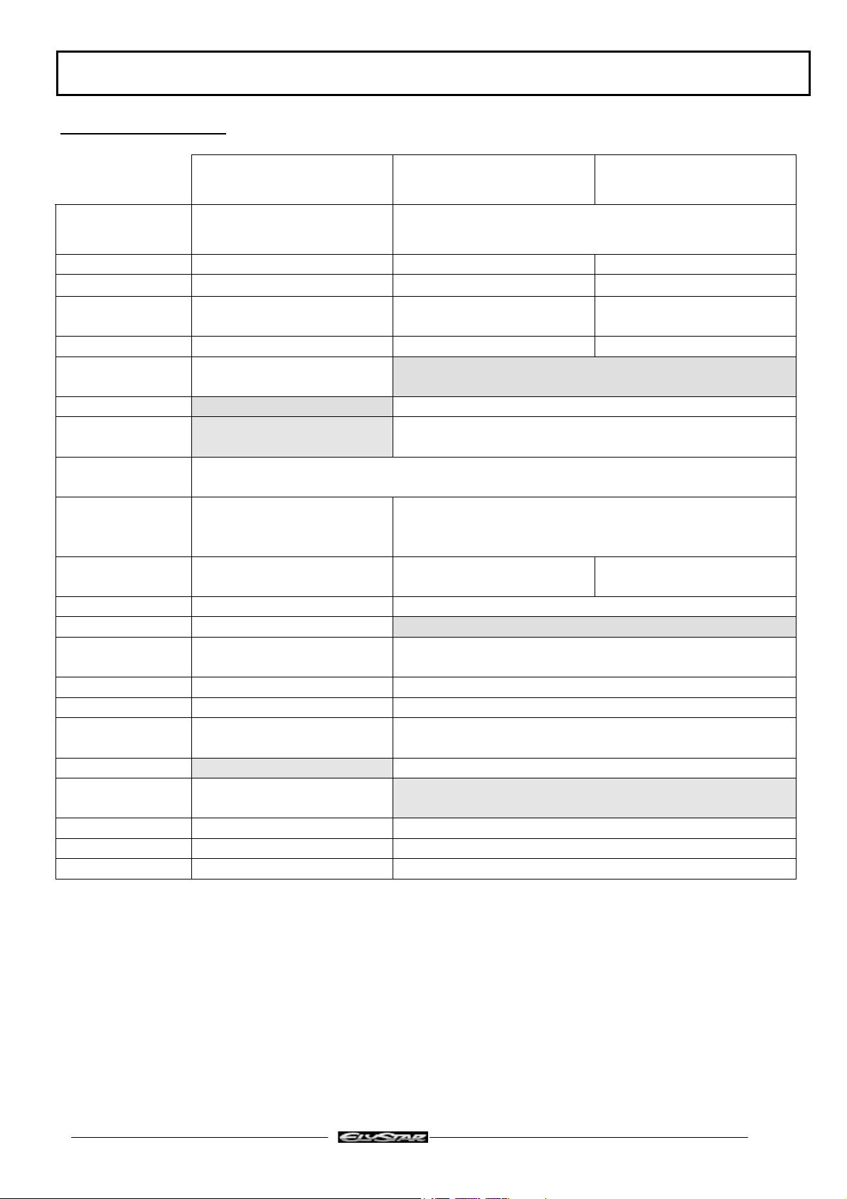
CHARACTERISTICS
CHARACTERISTICS
Type
FC5 Engine
50 cc
Air-cooled, single-cylinder
2-stroke injection
FD3 Engine
125 cc
FD4 Engine
150 cc
Single-cylinder 4-stroke coolant cooled
Bore x stroke 40.3 x 39.1 57 x 48.9 57 x 58.9
Cubic capacity 49.1 cc 124.8 cc 150.3 cc
Max. power
output
3.4 kW at 6900 rpm 9 kW at 8700 rpm 10.5 kW at 8200 rpm
Maximum torque 4.7 Nm at 6800 rpm 10.5 Nm at 7500 rpm 12.5 Nm at 6500 rpm
Gross
compression ratio
11,4
Timing Chain driven overhead camshaft, 2-valve
Engine oil
capacity
Relay box
capacity
Injection system
Ignition /
Carburettor
0.12 L.
TSDI
Two Stroke Direct
Injection
Electronic Fuel Injection
Synerject ECU Synerject ECU Synerject ECU
1.25 L.
EFI
Petrol injector Siemens green 37.028 Siemens black 8884
Air injector Synerject blue 37.073
Fuel pressure
regulator
Synerject Synerject
Petrol pump Synerject Synerject
Throttle unit Bing 235 011 Bing 7229 104
Temperature
sensor
Synerject Synerject
Lubrication Trochoidal pump with relief valve
Lubrication
Oil pump
Mikuni ESOP-03
Spark plug NGK CPR8E NGK CR7E
Magneto flywheel Mitsuba 180W Mitsuba 235 W
Starter motor Mitsuba 250 W Mitsuba 440 W
Reproduction or translation, even partial, are forbidden without the written consent of Peugeot Motocycles
Page : 3
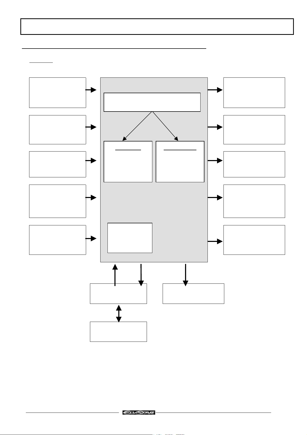
PRESENTATION OF THE 4 STROKE INJECTION SYSTEM (EFI)
PRESENTATION OF THE 4 STROKE INJECTION SYSTEM (EFI)
Synoptics
Throttle unit Petrol injector
INJECTION / IGNITION
ECU
Engine position and
speed sensor
Engine
temperature sensor
Software:
Manages
system
functioning
Calibration:
Values specific
to machine
(mapping)
Idle control valve
Ignition coil
Battery voltage Fuel pump
ECU locking
Inlet air pressure
and temperature
sensor.
code
Engine temperature
gauge
Diagnostic plug Diagnostic lamp
Immobiliser
module
Reproduction or translation, even partial, are forbidden without the written consent of Peugeot Motocycles
Page : 4
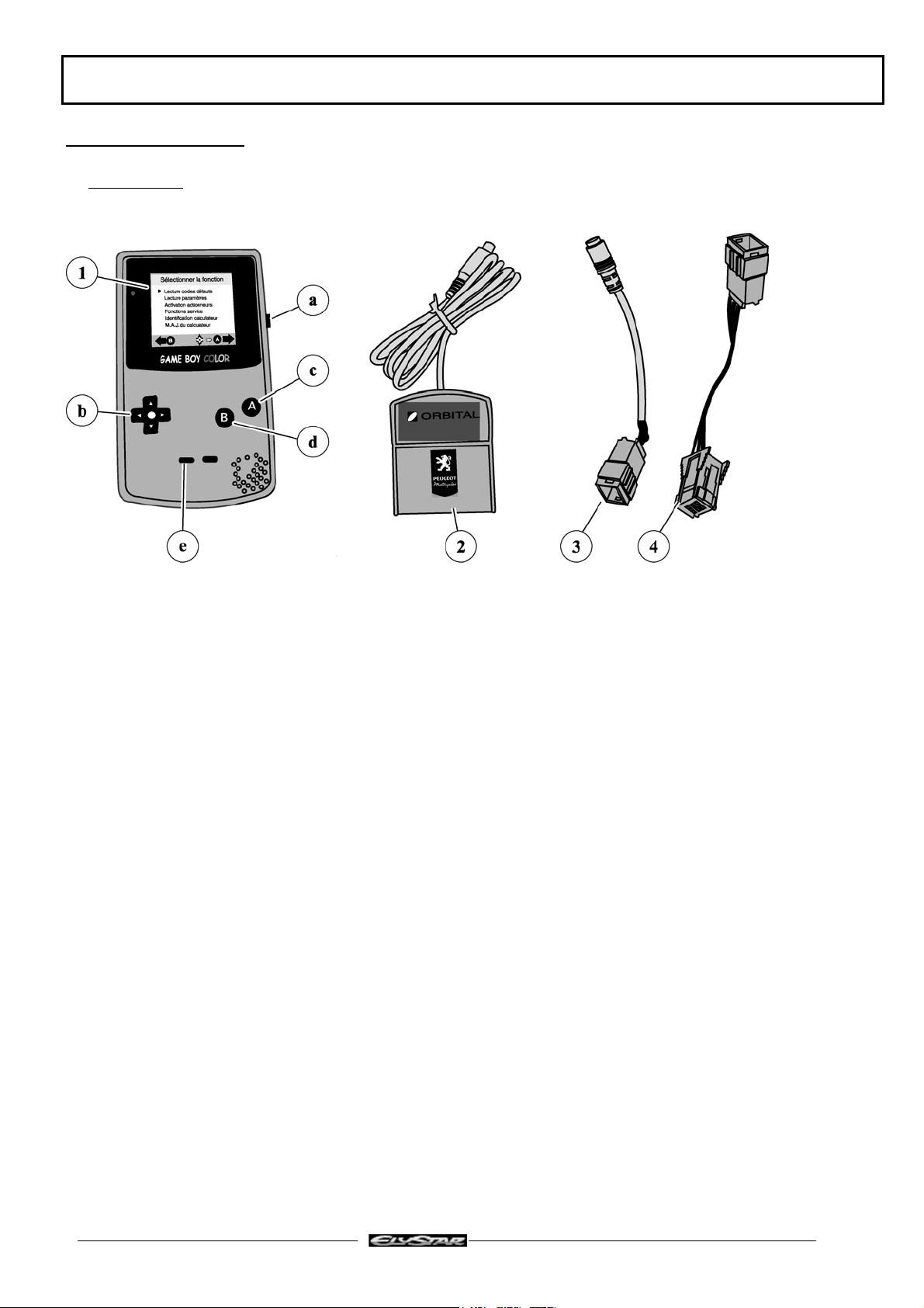
DIAGNOSTIC TOOL
Presentation
DIAGNOSTIC TOOL
1 - A screen, a Nintendo © Game Boy ™ Color console
a - on/off button
b - arrows: select key
c - button A: confirm button
d - button B: return button
e - select button: for help
2 - Cartridge, containing the software for dialog between the machine and the screen
3 - Interface cable between the machine and the tool for diagnostic of the 4-stroke injection system (EFI)
4 - Interface cable between the machine and interface cable (3) for diagnostic of the ABS/PBS system
Reproduction or translation, even partial, are forbidden without the written consent of Peugeot Motocycles
Page : 5
DIAGNOSTIC TOOL
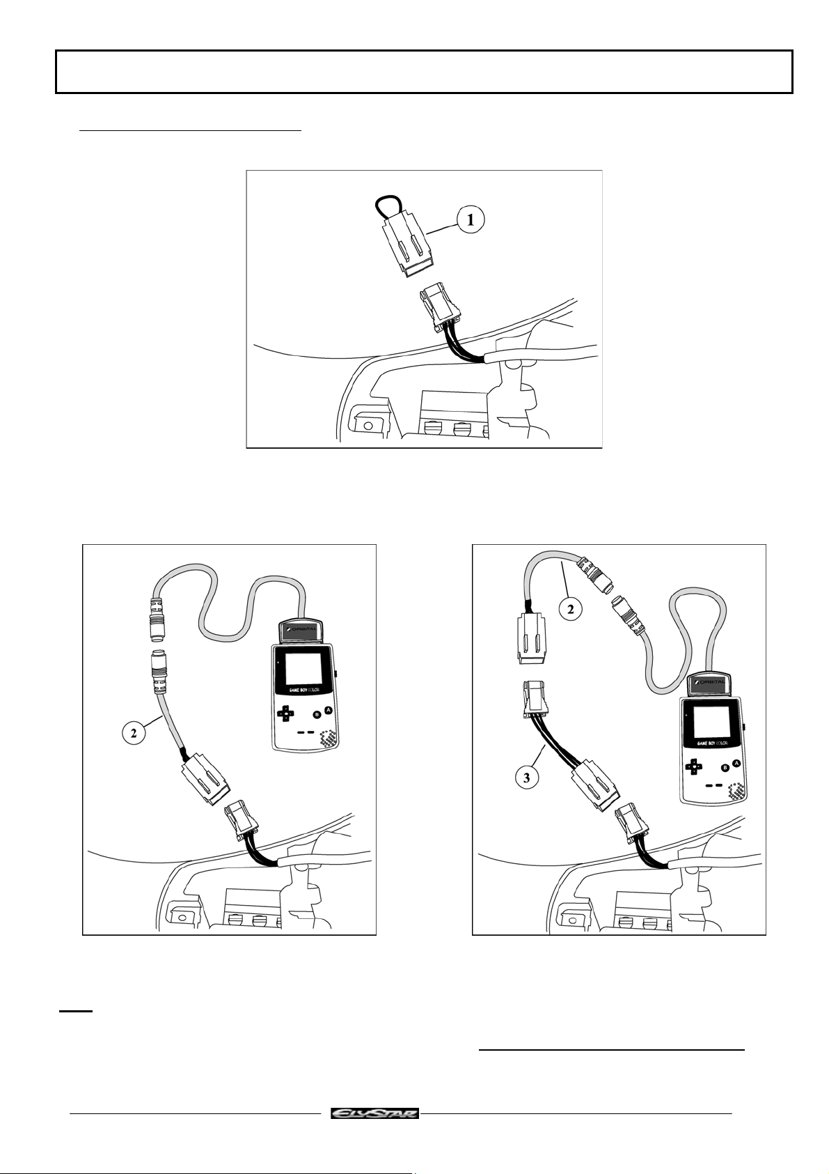
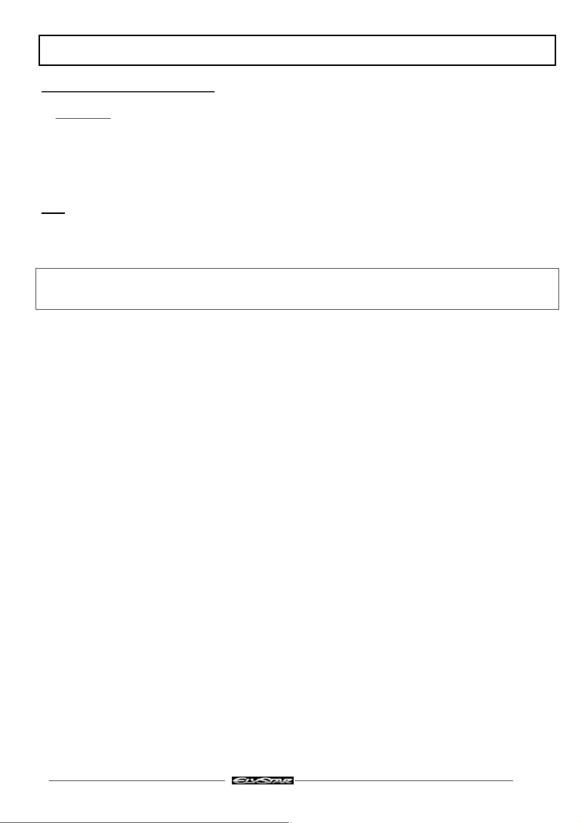
Connection of the diagnostic tool
1. Turn on the ignition (to unlock the ECU and authorise engine starting)
2. Remove the diagnostic plug loop (1)
3. Connect the diagnostic tool to the machine using:
a - Interface cable (2) for EFI system diagnostic b - Interface cable (2) + special interface (3) ref:
756449 for diagnostic of the ABS/PBS system
4. Turn on the diagnostic tool.
Note:
Never forget to re-connect the diagnostic plug loop. The loop provides the link between the
immobiliser module and the injection/ignition ECU, and is essential to be able to start the engine
Reproduction or translation, even partial, are forbidden without the written consent of Peugeot Motocycles
Page : 6
SPECIAL IMPORTANT POINTS
SPECIAL IMPORTANT POINTS
Fuel system
Before commencing work, clean the power unit.
The injection system is composed of precision components and cannot withstand impurities. Perfectly
clean working conditions are therefore essential.
Note:
Before carrying out any work, leave the engine to cool for a minimum of 2 hours.
Petrol is highly inflammable, do not smoke in the working area and avoid proximity to flames or sparks.
Work in a clear and well-ventilated area.
The fuel pipes must be changed if they show signs of wear, cracks, etc.
Moreover, the hoses and clips are specific and must only be replaced by the original genuine parts
Reproduction or translation, even partial, are forbidden without the written consent of Peugeot Motocycles
Page : 7
TIGHTENING TORQUES
TIGHTENING TORQUES
50 cc Engine
Cylinder head 1.2 m.daN
Cylinder casings 1 m.daN
Covers 1 m.daN
Inlet manifold 1 m.daN
Starter motor 1 m.daN
Rotor 4 m.daN
Stator 1 m.daN
Engine speed sensor. 1 m.daN
Turbine 1 m.daN
Drive pulley 4 m.daN
Driven pulley 4.5 m.daN
Spark plug 1 m.daN
Compressor 0.65 m.daN
Injection rail 0.65 m.daN
125-150 cc Engine
Cylinder head 2.3 m.daN
Cylinder casings 1 m.daN
Covers 1 m.daN
Starter motor 1 m.daN
Rotor 7 m.daN
Stator 1 m.daN
Engine speed sensor. 0.65 m.daN
Drive pulley 7 m.daN
Driven pulley 7 m.daN
Spark plug 1 m.daN
Injection rail 1 m.daN
Reproduction or translation, even partial, are forbidden without the written consent of Peugeot Motocycles
Page : 8
SPECIAL TOOLS
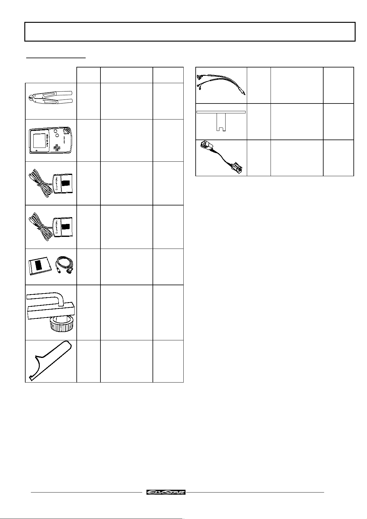
SPECIAL TOOLS
Tool N° Description Used with
750539 Tie-wrap pliers
755878 diagnostic tool
(Color Gameboy)
755806 French cartridge 755878
755807 Export cartridge 755878
755806
755807
756017 Petrol injection
power supply
harness
TSDI
756076 Tank gauge spanner
EFI
756449 ABS/PBS interface
cable for diagnostic
tool
755878
755806
755807
755990 Diagnostic tool
update software
755996 Hose clamp
756056 Tank ring spanner
755878
755806
755807
Reproduction or translation, even partial, are forbidden without the written consent of Peugeot Motocycles
Page : 9
INSTRUMENT PANEL
Warning lights description and meanings
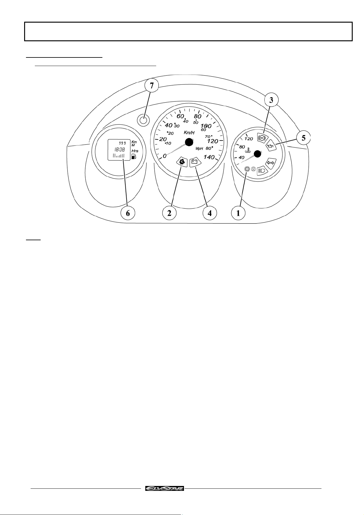
INSTRUMENT PANEL
Note: The above diagram shows the Elystar 125-150 cc speedo
On the 50 cc Elystar, there is no the engine temperature gauge and ABS/PBS warning light
When ignition is turned on:
1 - The coded immobiliser diagnostic LED comes on (1) and goes off after 0.5 seconds
If there is an immobiliser fault, the LED flashes several times depending on the fault detected then stays on
2 - The EFI (Electronic Fuel Injection) or TSDI (Two Stroke Direct injection) diagnostic warning light (2)
comes on then goes off when the engine is started
If there is an injection system fault, the lamp flashes or stays on
3 – The ABS/PBS (Anti Blocking System/Powered Braking System) diagnostic warning light (3) comes on
then goes off once the vehicle is on the move (over 5 km/h) (Elystar only)
If there is an ABS/PBS fault, the lamp stays on
4 - The battery charge light (4) does not come on
However, this warning light can come on at under 11.6 V or over 15.8 V to show there is a fault in the battery
charging circuit
5 - The oil pressure warning light (5) comes on then goes off when the engine starts. This warning light comes
on when under 0.5 bar to indicate a drop in engine oil pressure (stop the machine as quickly as possible) (on
the Elystar 50 cc, this warning light is used for the separate lubrication system oil level, and comes on 3
seconds after turning on the ignition)
Reproduction or translation, even partial, are forbidden without the written consent of Peugeot Motocycles
Page : 10
INSTRUMENT PANEL
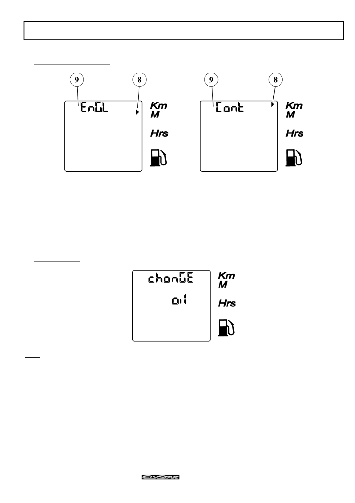
Changing the speedo units
Note: This function is available if the machine has done under 10 kms
The choice of distance unit (km/miles) is by pressing the control button (7) before turning on the ignition and
holding it down until the display lights up.
Unit selection is by pressing the control button (7), the arrow (8) is positioned against the unit selected and
"Engl" or "Cont" is displayed at (9)
The choice is confirmed by pressing the control button (7) for more than 2 seconds
Service function
Note: This function is only available on Elystar 125-150 cc and if the machine has covered over 10 kms
As from 5000 kms and once this distance is exceeded, when the ignition is turned on, the message "change
oil" appears for 10 seconds in place of the clock display
This display tells the customer that his machine is due for its first service.
After servicing the machine, the service counter is reset by pressing on the control button (7) before turning
on the ignition
And so on, after every 5000 km covered, the same display is shown to remind the customer that servicing is
due (5000 kms after the previous service counter reset)
Reproduction or translation, even partial, are forbidden without the written consent of Peugeot Motocycles
Page : 11
TRANSPONDER IMMOBILISER
TRANSPONDER IMMOBILISER
Precautions:
Check that the diagnostic plug loop is fitted. The loop provides the link between the immobiliser module and
the injection/ignition ECU, and is essential to be able to start the engine
If the loop is not fitted, the transponder LED diagnostic is always the same (no link between the immobiliser
and the ECU)
Note: Fitting of a 5 kΩ resistive suppressor along with a resistive spark plug is essential for the proper
functioning of the engine
System programming
The machine is supplied with a notched key (master) and a black key
The system is programmed in the factory
It is possible to program up to 7 black keys
The key memory procedure is the same as the AEC400 and ACI100 system
Reminder of the key memory procedure
1. Using the master key, set the ignition to on, and when the LED lights, turn off the ignition
2. Within a maximum of 15 seconds of cutting off the ignition with the master key, turn on the ignition with
the black key, and when the LED comes on turn off the ignition (repeat the operation for each black key to
be memorised (maximum of 7 black keys))
3. Within a maximum of 15 seconds of turning off the ignition with the last key memorised, turn on the
ignition with the master key, and when the LED comes on, turn off the ignition
Key memory check
Using the master key, turn on the ignition, the LED on the instrument panel comes on for 0.5 seconds and
flashes a number of times. The number of flashes indicates the number of keys memorised, including the
master key
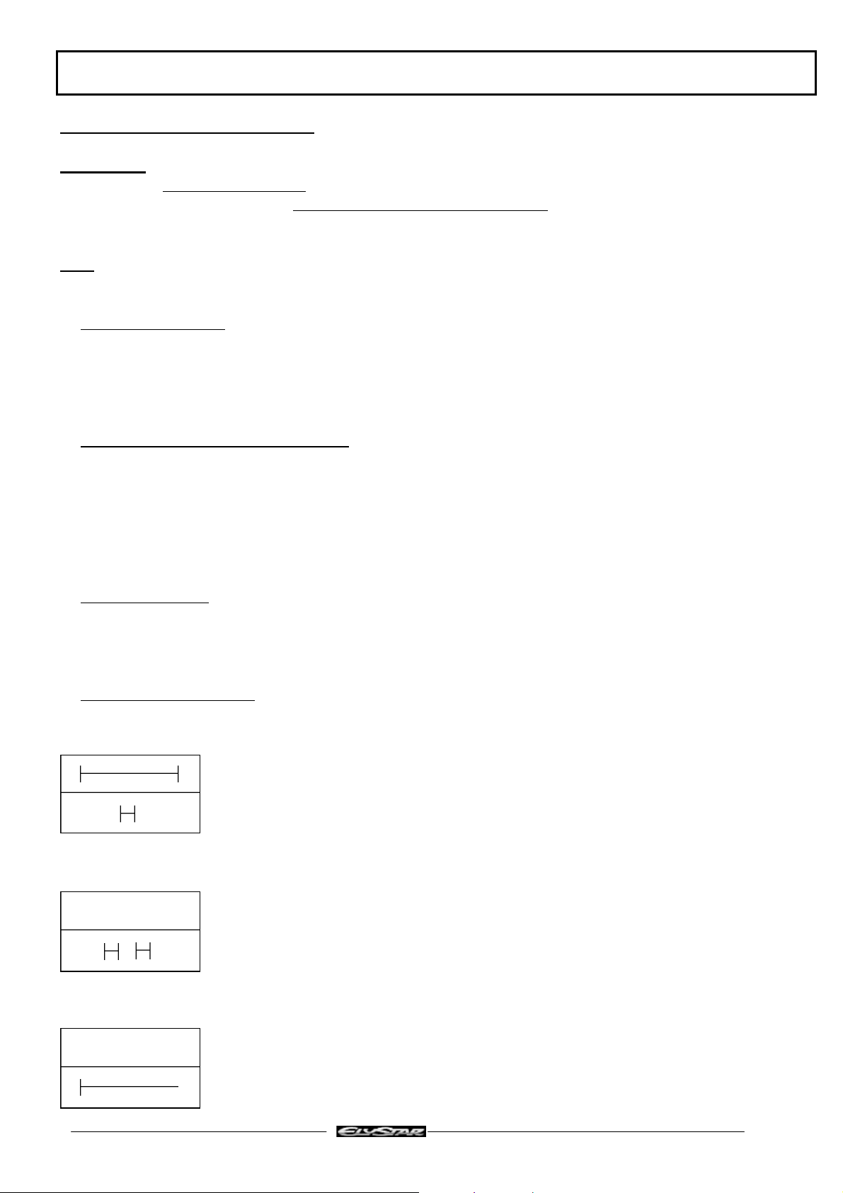
Diagnostic LED readings
There are three successive diagnostic LED lighting phases when the ignition is turned on with a black key
Phase 1: System status
Lights for 2 seconds: Immobiliser not programmed
Lights for 0.5 seconds: Immobiliser programmed
Phase 2: Diagnostic
Does not light: No fault detected
Lights 1 to 4 times for 0.5 seconds Fault detected
Phase 3: Starting enabled
Does not light: Starting enabled (if engine does not start, see troubleshooting chart)
Light stays on Starting not enabled
Reproduction or translation, even partial, are forbidden without the written consent of Peugeot Motocycles
Page : 12

TRANSPONDER IMMOBILISER
Additional information
Before carrying out any work on the transponder immobiliser, have the machine master key and black key to
hand.
If the engine will not start, a first diagnostic may be carried out using the LED before checking the other parts
of the ignition system.
Note: Do not remove the diagnostic plug loop
In case of a fault, do not use an immobiliser module or ECU from another machine to carry out tests. The
keys, immobiliser module and ECU programmed on another machine form an assembly, are linked by a code
and must under no circumstances be separated.
Important: If an ECU is changed without memorising the keys, do not turn on the ignition more than 16
times if the diagnostic loop is disconnected as beyond this number, the ECU immobiliser function is erased.
Reproduction or translation, even partial, are forbidden without the written consent of Peugeot Motocycles
Page : 13
TRANSPONDER IMMOBILISER
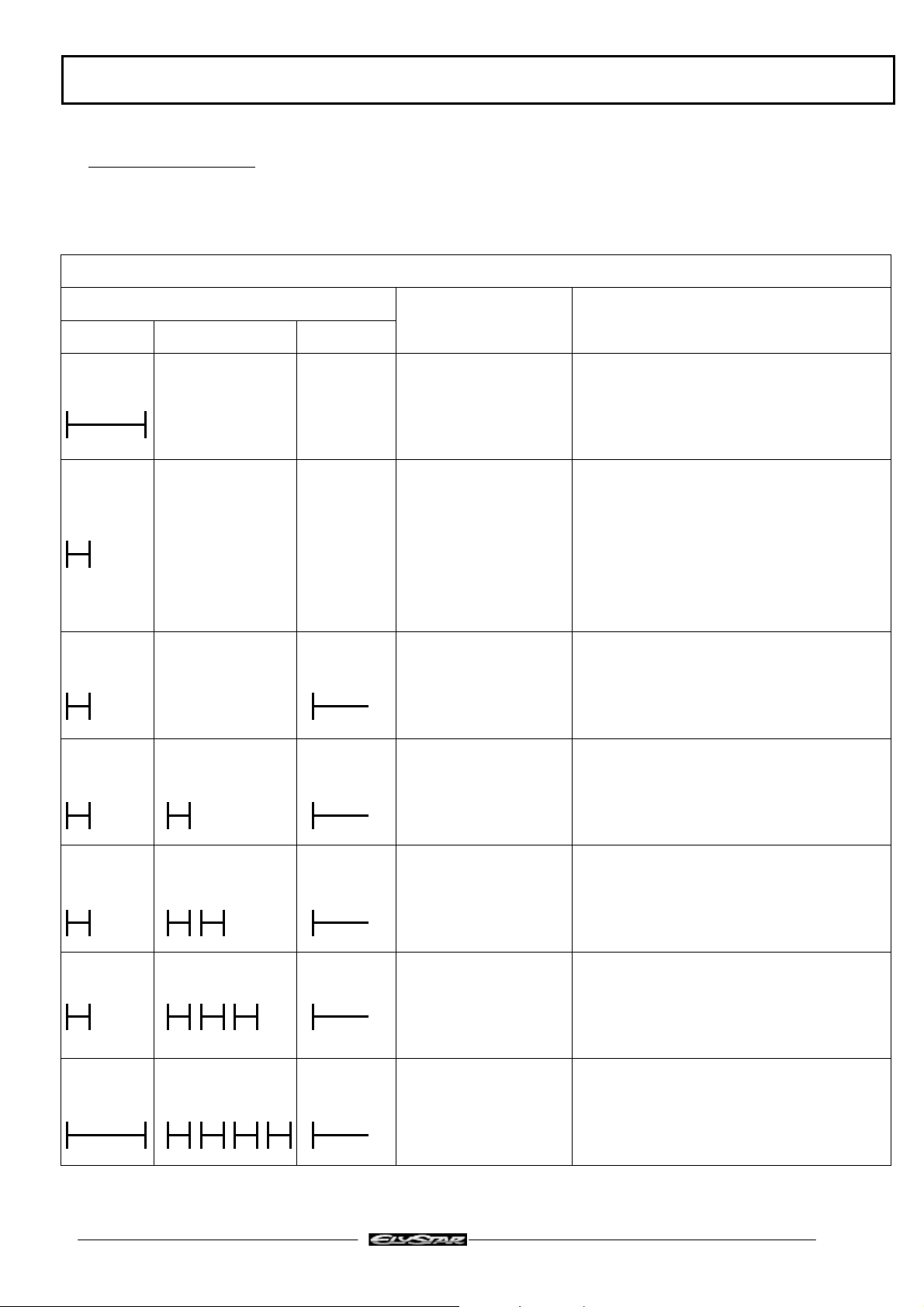
Troubleshooting chart
If the engine will not start, a first diagnostic may be carried out using the LED before checking the other parts
of the ignition system
TEST TO BE CARRIED OUT ONLY WITH THE BLACK KEY
LED SIGNAL
DISPLAYS SOLUTIONS
PHASE 1 PHASE 2 PHASE 3
2 s Blank immobiliser
connected to a blank
Program the system using the keys
ECU
Disconnect the diagnostic plug loop, turn
on the ignition with the master key and
0.5 s Blank ECU
connected to a
programmed
immobiliser
If OK, connect the diagnostic plug loop,
turn on the ignition with the master key
and start the engine or turn on the
start the engine
ignition for 3 seconds to memorise the
keys in the system
0.5 s Permanent
Black key and
programmed
immobiliser module
from another machine
0.5 s 0.5 s Permanent
No diagnostic plug
loop or faulty
immobiliser/ECU
link
0.5 s 0.5 s Permanent
Antenna disconnected
or faulty
Key without
transponder
0.5 s 0.5 s Permanent Wrong or faulty key
or programmed
immobiliser from
another machine
2 s 0.5 s Permanent Blank immobiliser
connected to a
programmed ECU
Refit the immobiliser and the original
keys or replace by a new one and
program the system using the original
keys
Refit the diagnostic plug loop or check
the interface wire between the
immobiliser and the ECU
Check the antenna connection and
resistance (17 Ω)
Change the key
Refit the original immobiliser or replace
by a new one and program the system
using the original keys
Program the system using the keys
Reproduction or translation, even partial, are forbidden without the written consent of Peugeot Motocycles
Page : 14
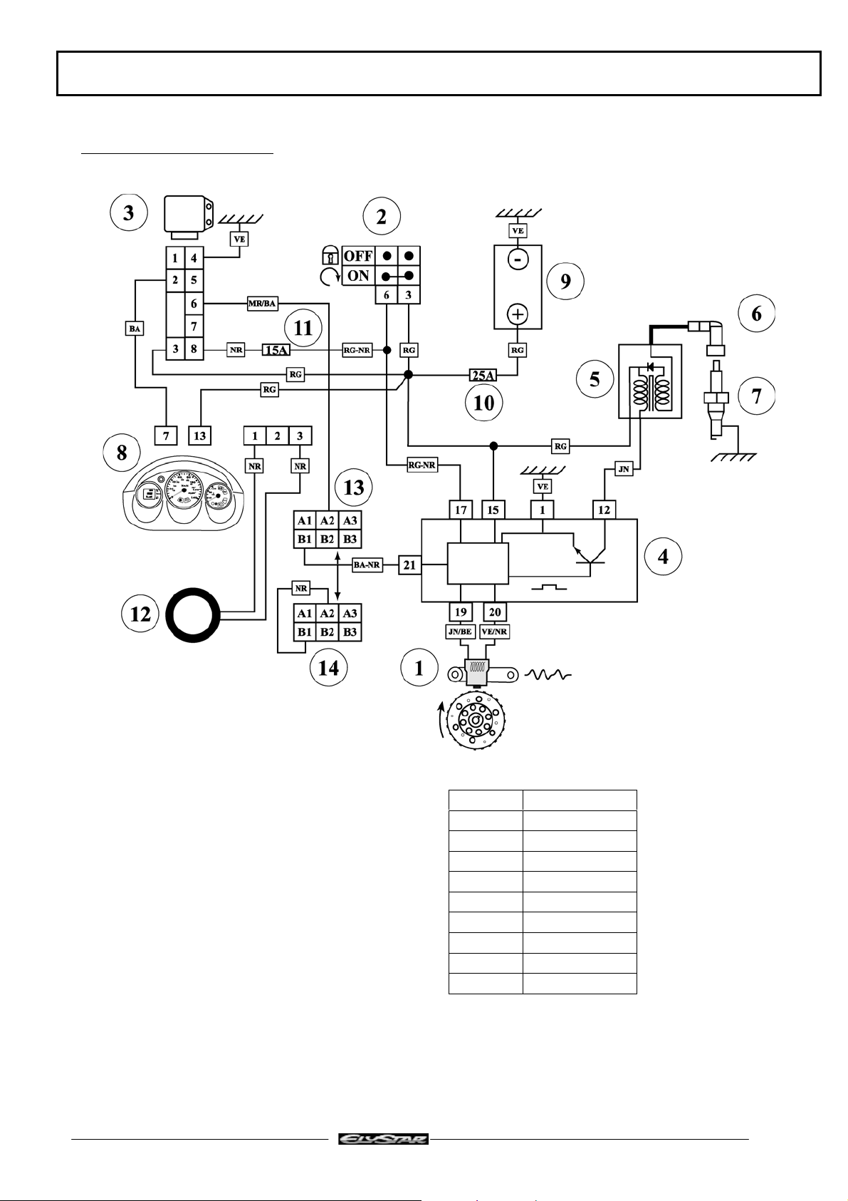
Ignition principle schematic
TRANSPONDER IMMOBILISER
1. Engine position sensor
2. Ignition switch
3. Immobiliser module
4. Injection ECU
5. HT coil
6. Resistive suppressor
7. Resistive spark plug
8. Instrument panel LED
9. Battery
10. 25A fuse
11. 15A fuse
12. Transponder antenna
13. Diagnostic plug
14. Diagnostic plug loop
Reproduction or translation, even partial, are forbidden without the written consent of Peugeot Motocycles
BA White
BA/NR White/Black
JN Yellow
JN/BE Yellow/Blue
MR/BA Brown/White
NR Black
RG Red
RG/NR Red/Black
VE Green
VE/NR Green/Black
Page : 15
 Loading...