

Peugeot 205 1983 1995 User Manual
1
Chapter 1
Routine maintenance and servicing
Air cleaner filter element renewal . . . . . . . . . . . . . . . . . . . . . . . . . . . . 26
Air conditioning system check . . . . . . . . . . . . . . . . . . . . . . . . . . . . . . 20
Automatic transmission fluid level check . . . . . . . . . . . . . . . . . . . . . 5
Automatic transmission fluid renewal . . . . . . . . . . . . . . . . . . . . . . . . 23
Auxiliary drivebelt check and renewal . . . . . . . . . . . . . . . . . . . . . . . . 9
Bodywork, paint and exterior trim check . . . . . . . . . . . . . . . . . . . . . . 18
Brake fluid renewal . . . . . . . . . . . . . . . . . . . . . . . . . . . . . . . . . . . . . .34
Clutch pedal stroke adjustment . . . . . . . . . . . . . . . . . . . . . . . . . . . . . 10
Coolant renewal . . . . . . . . . . . . . . . . . . . . . . . . . . . . . . . . . . . . . . . . . 33
Driveshaft bellows check . . . . . . . . . . . . . . . . . . . . . . . . . . . . . . . . . . 24
Engine oil and filter renewal . . . . . . . . . . . . . . . . . . . . . . . . . . . . . . . . 3
Exhaust system check . . . . . . . . . . . . . . . . . . . . . . . . . . . . . . . . . . . . 17
Emissions control systems check . . . . . . . . . . . . . . . . . . . . . . . . . . . 29
Front brake pad check . . . . . . . . . . . . . . . . . . . . . . . . . . . . . . . . . . . . 4
Fuel filter renewal - fuel injection models . . . . . . . . . . . . . . . . . . . . . 32
Handbrake check and adjustment . . . . . . . . . . . . . . . . . . . . . . . . . . . 15
Headlight beam alignment check . . . . . . . . . . . . . . . . . . . . . . . . . . . 19
Idle speed and mixture check and adjustment . . . . . . . . . . . . . . . . . 28
Ignition system check . . . . . . . . . . . . . . . . . . . . . . . . . . . . . . . . . . . . 27
Intensive maintenance . . . . . . . . . . . . . . . . . . . . . . . . . . . . . . . . . . . . 2
Introduction . . . . . . . . . . . . . . . . . . . . . . . . . . . . . . . . . . . . . . . . . . . . 1
Lock and hinge check and lubrication . . . . . . . . . . . . . . . . . . . . . . . . 12
Manual transmission oil level check . . . . . . . . . . . . . . . . . . . . . . . . . 21
Manual transmission oil renewal . . . . . . . . . . . . . . . . . . . . . . . . . . . . 22
Rear brake pad condition check - models with rear disc brakes . . . 14
Rear brake shoe check - models with rear drum brakes . . . . . . . . . 13
Road test . . . . . . . . . . . . . . . . . . . . . . . . . . . . . . . . . . . . . . . . . . . . . . 30
Seat belt check . . . . . . . . . . . . . . . . . . . . . . . . . . . . . . . . . . . . . . . . . 11
Spark plug renewal . . . . . . . . . . . . . . . . . . . . . . . . . . . . . . . . . . . . . . 7
Steering and suspension check . . . . . . . . . . . . . . . . . . . . . . . . . . . . 25
Throttle and choke cable lubrication and adjustment . . . . . . . . . . . . 8
Timing belt renewal . . . . . . . . . . . . . . . . . . . . . . . . . . . . . . . . . . . . . . 31
Underbody and fuel/brake line check . . . . . . . . . . . . . . . . . . . . . . . . 16
Underbonnet check for fluid leaks and hose condition . . . . . . . . . . . 6
1•1
Contents
Easy, suitable for
novice with little
experience
Fairly easy, suitable
for beginner with
some experience
Fairly difficult,
suitable for competent
DIY mechanic
Difficult, suitable for
experienced DIY
mechanic
Very difficult,
suitable for expert DIY
or professional
Degrees of difficulty
5
4
3
2
1

1•2 Servicing Specifications
Lubricants and fluids . . . . . . . . . . . . . . . . . . . . . . . . . . . . . . . . . . Refer to end of “Weekly checks”
Capacities
Engine oil
XV and XW series engines (including filter) . . . . . . . . . . . . . . . . . . . . 4.5 litres
XY and XU series engines (including filter) . . . . . . . . . . . . . . . . . . . . 5.0 litres
TU series engines (including filter) . . . . . . . . . . . . . . . . . . . . . . . . . . . 3.5 litres
Cooling system
XV8, XW7, TU9 and TU3 series engines . . . . . . . . . . . . . . . . . . . . . . . 5.8 litres
XY7 and XY8 engines . . . . . . . . . . . . . . . . . . . . . . . . . . . . . . . . . . . . . 6.0 litres
XU engines (except automatic transmission models) . . . . . . . . . . . . . 6.6 litres
XU engines (automatic transmission models) . . . . . . . . . . . . . . . . . . . 6.7 litres
TU1 series engine (except Van models) . . . . . . . . . . . . . . . . . . . . . . . 7.0 litres
TU1 series engine (Van models) . . . . . . . . . . . . . . . . . . . . . . . . . . . . . 5.8 litres
Manual transmission . . . . . . . . . . . . . . . . . . . . . . . . . . . . . . . . . . . . . . 2.0 litres
Automatic transmission
From dry . . . . . . . . . . . . . . . . . . . . . . . . . . . . . . . . . . . . . . . . . . . . . . . 6.2 litres
Drain and refill . . . . . . . . . . . . . . . . . . . . . . . . . . . . . . . . . . . . . . . . . . . 2.4 litres
Fuel tank . . . . . . . . . . . . . . . . . . . . . . . . . . . . . . . . . . . . . . . . . . . . . . . . 50 litres
Engine
Oil filter:
XV, XW and XY series engines . . . . . . . . . . . . . . . . . . . . . . . . . . . . . . Champion C204
XU and TU series engines . . . . . . . . . . . . . . . . . . . . . . . . . . . . . . . . . . Champion F104
Cooling system
Antifreeze mixture:
Protection down to - 15ºC (5ºF) . . . . . . . . . . . . . . . . . . . . . . . . . . . . . 27% antifreeze
Protection down to - 35ºC (- 31ºF) . . . . . . . . . . . . . . . . . . . . . . . . . . . 50% antifreeze
Note: Refer to Chapter 3 for further details.
Fuel system
Air cleaner filter element:
Pre-1988 carburettor engines . . . . . . . . . . . . . . . . . . . . . . . . . . . . . . . Champion W138
1988 onward carburettor engines . . . . . . . . . . . . . . . . . . . . . . . . . . . . Champion U401
Fuel injection engines . . . . . . . . . . . . . . . . . . . . . . . . . . . . . . . . . . . . . Champion W175
Fuel filter . . . . . . . . . . . . . . . . . . . . . . . . . . . . . . . . . . . . . . . . . . . . . . . . . Champion L205
Idle speed and mixture CO content . . . . . . . . . . . . . . . . . . . . . . . . . . . . Refer to Chapter 4A, 4B and 4C Specifications
Ignition system
Spark plugs:
XV8, XW7 and XY7 engines . . . . . . . . . . . . . . . . . . . . . . . . . . . . . . . . Champion RS9YCC or S281YC*
XY8 and XU5J engines . . . . . . . . . . . . . . . . . . . . . . . . . . . . . . . . . . . . Champion S7YCC or S279YC*
XU51C engines (up to 1988) . . . . . . . . . . . . . . . . . . . . . . . . . . . . . . . . Champion S9YCC or S281YC*
XU51C engines (from 1988) . . . . . . . . . . . . . . . . . . . . . . . . . . . . . . . . Champion RC9YCC or C9YCX*
XU5JA engines (up to 1988) . . . . . . . . . . . . . . . . . . . . . . . . . . . . . . . . Champion S7YCC or S279YC*
XU5JA (from 1988), XU5JA/K, XU9JA, XU9JA/K, XU9JA/Z and
XU9JA/L engines . . . . . . . . . . . . . . . . . . . . . . . . . . . . . . . . . . . . . . . . Champion RC7YCC or C7YCX*
TU9 series, TU1 series, TU3 and TU3A engines . . . . . . . . . . . . . . . . . Champion RC9YCC or C9YCX*
TU3S engines . . . . . . . . . . . . . . . . . . . . . . . . . . . . . . . . . . . . . . . . . . . Champion RC7YCC or C7YCX*
*Peugeot recommendation
Spark plug electrode gap** . . . . . . . . . . . . . . . . . . . . . . . . . . . . . . . . . . . 0.7 to 0.8 mm
**The spark plug electrode gap quoted is that recommended by Champion for their specified plugs listed above. If spark plugs of any other type
are to be fitted, refer to their manufacturer’s recommendations.
Brakes
Front brake pad minimum lining thickness . . . . . . . . . . . . . . . . . . . . . . . 2.0 mm
Rear brake shoe minimum lining thickness . . . . . . . . . . . . . . . . . . . . . . 1.0 mm
Rear brake pad minimum lining thickness . . . . . . . . . . . . . . . . . . . . . . . 2.0 mm
Tyre pressures . . . . . . . . . . . . . . . . . . . . . . . . . . . . . . . . . . . . . . . . See “Weekly checks”
Torque wrench settings Nm lbf ft
Spark plugs . . . . . . . . . . . . . . . . . . . . . . . . . . . . . . . . . . . . . . . . . . . . . . . 17 13
Manual transmission drain/filler plugs
BE1 and BE3 transmissions:
Main gearbox drain plug . . . . . . . . . . . . . . . . . . . . . . . . . . . . . . . . . 10 7
Final drive drain plug . . . . . . . . . . . . . . . . . . . . . . . . . . . . . . . . . . . . 30 22
MA transmission . . . . . . . . . . . . . . . . . . . . . . . . . . . . . . . . . . . . . . . . . 25 19

Maintenance schedule 1•3
1
Every 250 miles (400 km) or weekly
mm
˛
Refer to “Weekly checks”.
Every 36 000 miles (58 000 km) or
3 years - whichever comes sooner
In addition to all the items listed above, carry out the following:
mm
˛
Renew the timing belt (Section 31).
Note: Although the normal interval for timing belt renewal is 72 000
miles (120 000 km), It is strongly recommended that the timing belt
renewal interval is halved to 36 000 miles (60 000 km) on vehicles
which are subjected to intensive use, ie. mainly short journeys or a lot
of stop-start driving. The actual belt renewal interval is therefore very
much up to the individual owner, but bear in mind that severe engine
damage will result if the belt breaks.
Every 6000 miles (9000 km) or
6 months - whichever comes sooner
In addition to all the items listed above, carry out the following:
mm Renew the engine oil and filter (Section 3)*.
mm
˛
Check the condition of the front brake pads, and renew if
necessary (Section 4).
mm
˛
Check the automatic transmission fluid level and top-up if
necessary (Section 5).
Note: Renewal of the engine oil filter at this service interval is only
necessary on models fitted with the XU9J1/L engine and automatic
transmission. On all other models, oil filter renewal is recommended
at every second oil change (ie 12 000 miles/12 months).
Every 48 000 miles (80 000 km) or
4 years - whichever comes sooner
mm
˛
Renew the fuel filter - fuel injection models (Section 32).
Every 12 000 miles (18 000 km) or
12 months - whichever comes sooner
In addition to all the items listed above, carry out the following:
mm
˛
Check all underbonnet components and hoses for fluid leaks
(Section 6).
mm
˛
Renew the spark plugs (Section 7).
mm
˛
Check, adjust and lubricate the throttle and choke cables
(Section 8).
mm
˛
Check the condition of the auxiliary drivebelt, and renew if
necessary (Section 9).
mm
˛
Check the clutch pedal stroke adjustment (Section 10).
mm
˛
Check the condition of the seat belts (Section 11).
mm
˛
Lubricate the locks and hinges (Section 12).
mm
˛
Check the condition of the rear brake shoes and renew if
necessary - rear drum brake models (Section 13).
mm
˛
Check the condition of the rear brake pads and renew if
necessary - rear disc brake models (Section 14).
mm
˛
Check the operation of the handbrake (Section 15).
mm
˛
Inspect the underbody and the brake hydraulic pipes and hoses
(Section 16).
mm
˛
Check the condition of the fuel lines (Section 16).
mm
˛
Check the condition and security of the exhaust system (Section 17).
mm
˛
Check the condition of the exterior trim and paintwork (Section 18).
mm
˛
Check the headlight beam alignment (Section 19).
mm
˛
Check the operation of the air conditioning system (Section 20).
Every 72 000 miles (120 000 km)
In addition to all the items listed above, carry out the following:
mm
˛
Renew the timing belt (Section 31).
Note: This is the interval recommended by Peugeot, but we
recommend that the belt is changed more frequently, at 36 000 miles
(60 000 km) - see above
Every 24 000 miles (36 000 km) or
2 years - whichever comes sooner
In addition to all the items listed above, carry out the following:
mm
˛
Check the manual transmission oil level, and top-up if necessary
(Section 21).
mm
˛
Renew the manual transmission oil (pre-1988 BE1 transmissions
only) (Section 22).
mm
˛
Renew the automatic transmission fluid (Section 23).
mm
˛
Check the condition of the driveshaft bellows (Section 24).
mm
˛
Check the steering and suspension components for condition
and security (Section 25).
mm
˛
Renew the air cleaner filter element (Section 26).
mm
˛
Check the ignition system (Section 27).
mm
˛
Check the idle speed and mixture adjustment (Section 28).
mm
˛
Check the condition of the emissions control system hoses and
components (Section 29).
mm
˛
Carry out a road test (Section 30).
Every 2 years (regardless of mileage)
mm
˛
Renew the coolant (Section 33).
mm
˛
Renew the brake fluid (Section 34).
The maintenance intervals in this manual
are provided with the assumption that you,
not the dealer, will be carrying out the work.
These are the average maintenance intervals
recommended for vehicles driven daily under
normal conditions. Obviously some variation
of these intervals may be expected depending
on territory of use, and conditions
encountered. If you wish to keep your vehicle
in peak condition at all times, you may wish to
perform some of these procedures more
often. We encourage frequent maintenance
because it enhances the efficiency,
performance and resale value of your vehicle.
If the vehicle is driven in dusty areas, used
to tow a trailer, driven frequently at slow
speeds (idling in traffic) or on short journeys,
more frequent maintenance intervals are
recommended.
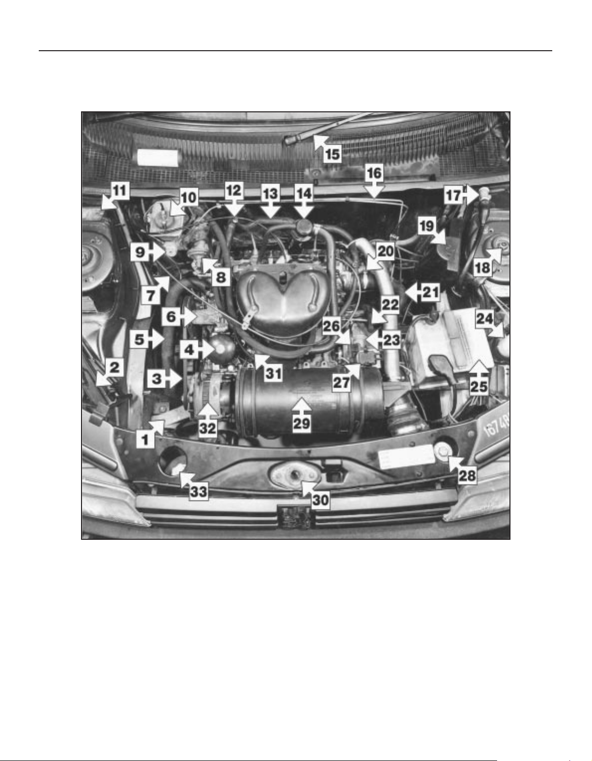
1•4 Maintenance - component location
Underbonnet view of a 1360 cc GT model (XY8 series engine)
1 Right-hand front engine mounting
2 Jack
3 Drivebelt
4 Oil filter
5 Bottom hose
6 Water pump
7 Throttle cable
8 Fuel pump
9 Brake master cylinder
10 Brake fluid reservoir filler cap
11 Vehicle identification plate
12 Choke cable
13 Heater hose
14 Oil filler cap/crankcase ventilation filter
15 Windscreen wiper arm
16 Hydraulic brake lines
17 Cooling fan motor resistor
18 Front suspension shock absorber top
mounting nut
19 Ignition coil cover
20 Distributor
21 Bottom hose
22 Clutch release fork
23 Clutch housing
24 Washer reservoir
25 Battery
26 Ignition timing aperture
27 Diagnostic socket
28 Radiator filler cap
29 Air cleaner
30 Bonnet lock
31 Oil pressure switch
32 Alternator
33 Cooling system expansion
bottle
Maintenance - component location 1•5
1
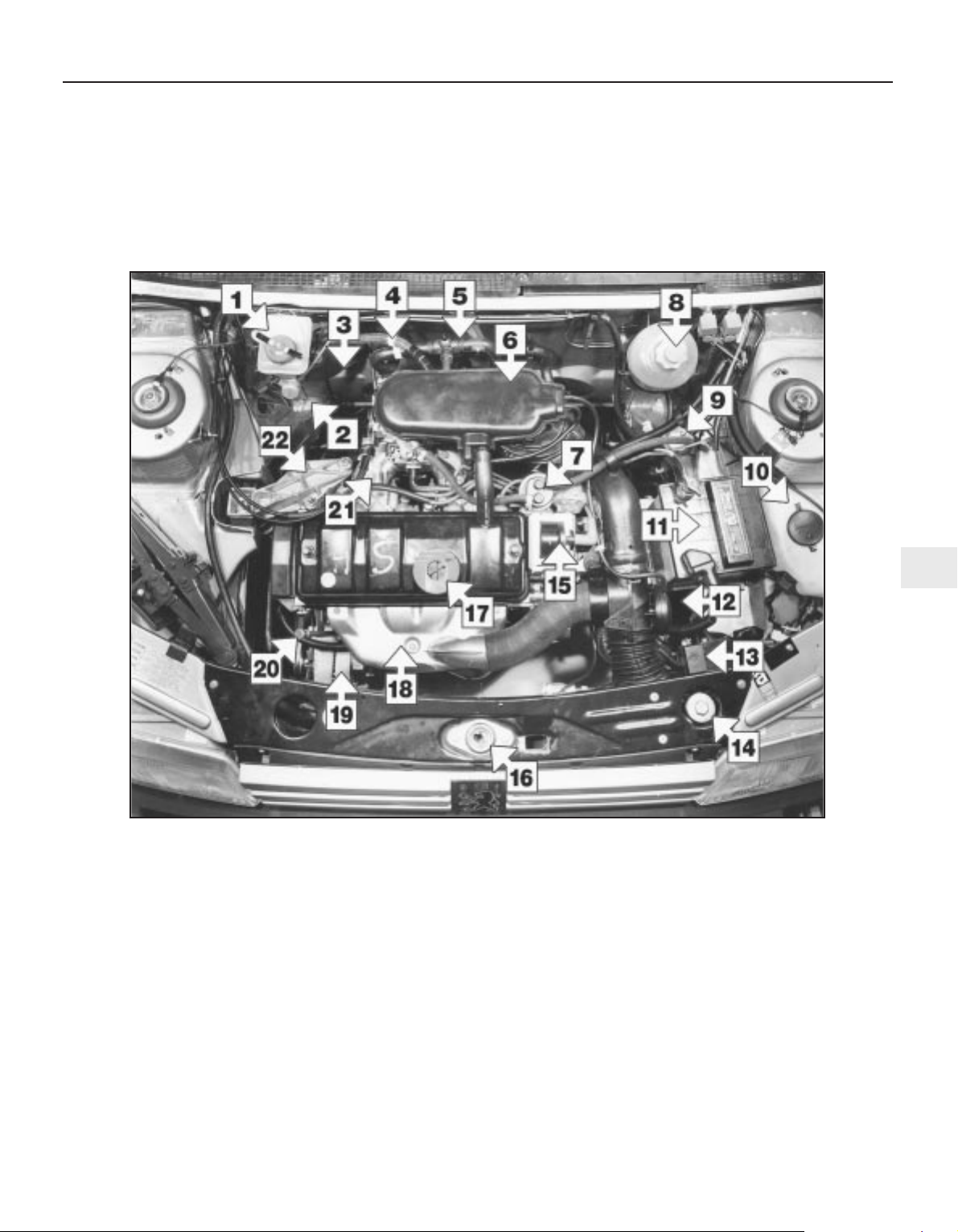
Underbonnet view of a 1360 cc XS model (TU series engine)
1 Brake fluid reservoir filler cap
2 Brake master cylinder
3 Brake vacuum servo unit
4 Servo vacuum hose
5 Cooling system bleed screw
6 Air cleaner cover
7 Fuel pump
8 Cooling system expansion bottle
9 Fuel filter
10 Washer fluid reservoir
11 Battery
12 Air temperature control unit
13 Auxiliary fusebox
14 Radiator filler cap
15 Ignition coil
16 Bonnet lock
17 Engine oil filler cap
18 Exhaust manifold hot air shroud
19 Alternator
20 Engine oil level dipstick
21 Inlet manifold
22 Right-hand engine mounting
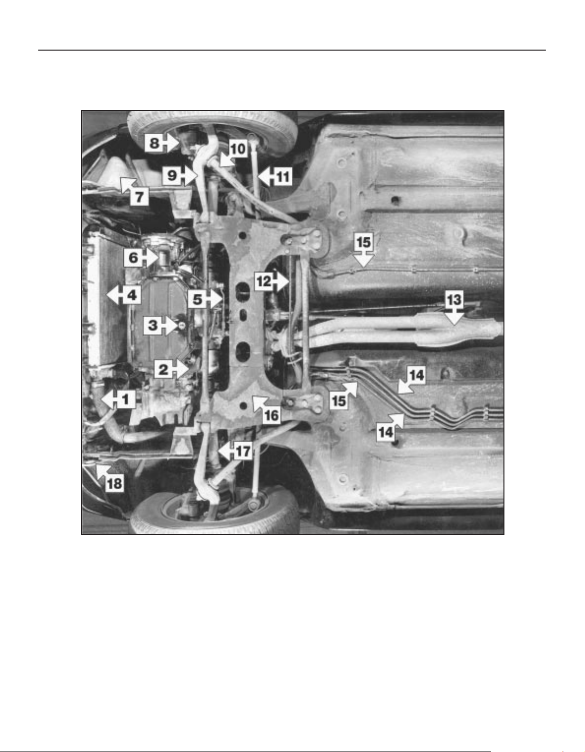
1•6 Maintenance - component location
Front underside view of a 1360 cc GT model
1 Bottom hose
2 Reverse lamp switch
3 Engine/transmission oil drain plug
4 Radiator
5 Gear linkage
6 Clutch housing and transfer gear
assembly
7 Washer reservoir
8 Disc caliper
9 Lower suspension arm
10 Anti-roll bar
11 Track rod
12 Guide bar
13 Exhaust front pipe
14 Fuel feed and return pipes
15 Hydraulic brake lines
16 Subframe
17 Driveshaft
18 Front towing eye
Maintenance - component location 1•7
1
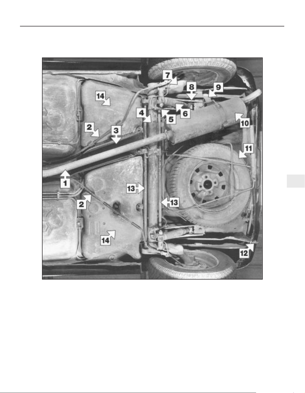
Rear underside view of a 1360 cc GT model
1 Exhaust front pipe
2 Handbrake cables
3 Heatshield
4 Rear suspension cross-tube
5 Brake hydraulic flexible hose
6 Rear shock absorber
7 Trailing arm
8 Side-member
9 Exhaust rubber mounting
10 Exhaust rear silencer
11 Spare wheel
12 Rear towing eye
13 Torsion bars
14 Fuel tank
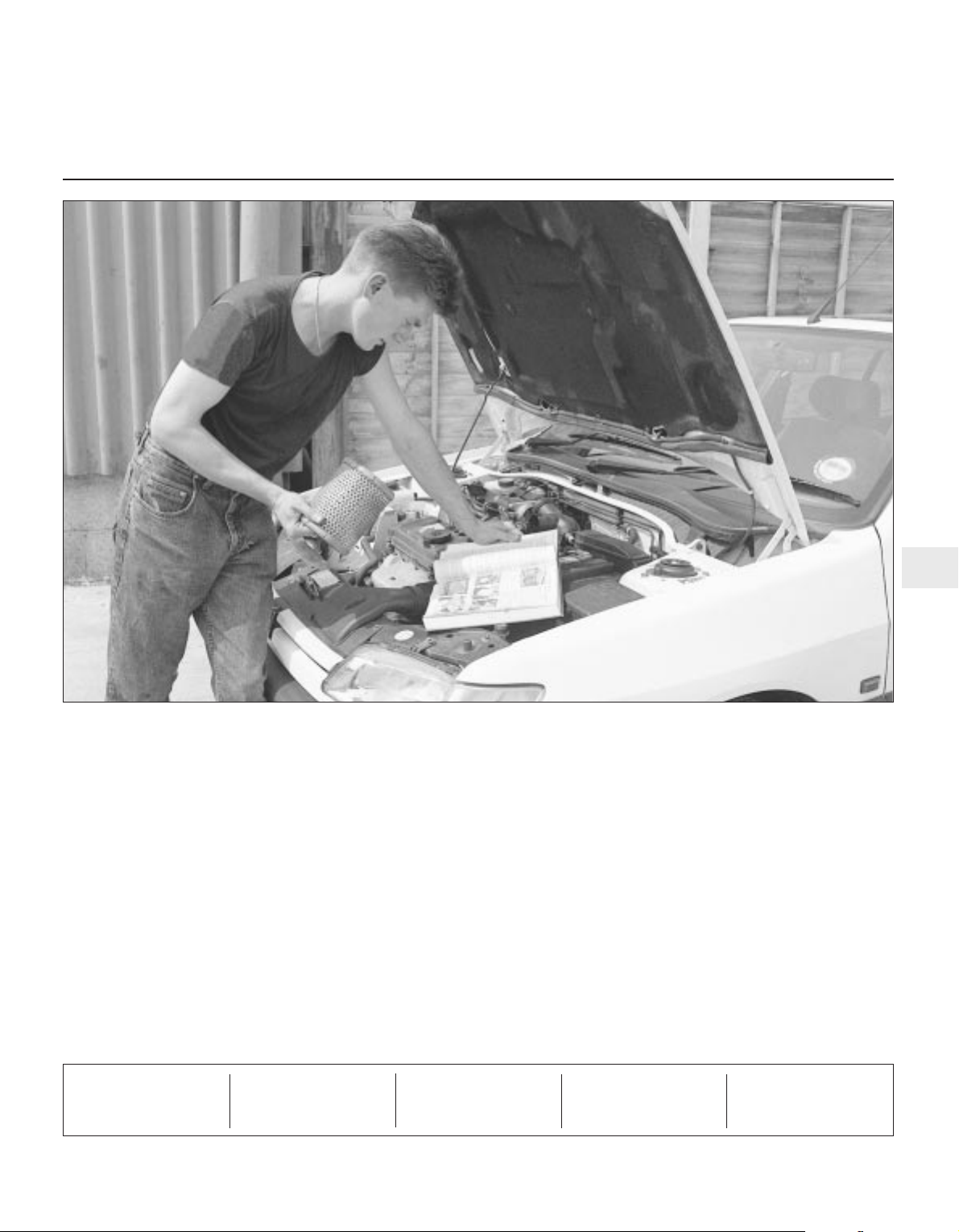
1 Introduction
This Chapter is designed to help the home
mechanic maintain his/her vehicle for safety,
economy, long life and peak performance.
This Chapter contains a master
maintenance schedule, followed by Sections
dealing specifically with each task in the
schedule. Visual checks, adjustments,
component renewal and other helpful items
are included. Refer to the accompanying
illustrations of the engine compartment and
the underside of the vehicle for the locations
of the various components.
Servicing your vehicle in accordance with
the mileage/time maintenance schedule and
the following Sections will provide a planned
maintenance programme, which should result
in a long and reliable service life. This is a
comprehensive plan, so maintaining some
items but not others at the specified service
intervals will not produce the same results.
As you service your vehicle, you will
discover that many of the procedures can and should - be grouped together, because of
the particular procedure being performed, or
because of the close proximity of two
otherwise-unrelated components to one
another. For example, if the vehicle is raised
for any reason, the exhaust should be
inspected at the same time as the suspension
and steering components.
The first step of this maintenance
programme is to prepare yourself before the
actual work begins. Read through all the
Sections relevant to the work to be carried
out, then make a list and gather together all
the parts and tools required. If a problem is
encountered, seek advice from a parts
specialist or a dealer service department.
2 Intensive maintenance
1 If, from the time the vehicle is new, the
routine maintenance schedule is followed
closely, and frequent checks are made of fluid
levels and high-wear items, as suggested
throughout this manual, the engine will be
kept in relatively good running condition, and
the need for additional work will be minimised.
2 It is possible that there will be some times
when the engine is running poorly due to the
lack of regular maintenance. This is even more
likely if a used vehicle, which has not received
regular and frequent maintenance checks, is
purchased. In such cases, additional work
may need to be carried out, outside of the
regular maintenance intervals.
3 If engine wear is suspected, a compression
test (refer to Chapter 2A, B or C) will provide
valuable information regarding the overall
performance of the main internal components.
Such a test can be used as a basis to decide
on the extent of the work to be carried out. If,
for example, a compression test indicates
serious internal engine wear, conventional
maintenance as described in this Chapter will
not greatly improve the performance of the
engine, and may prove a waste of time and
money, unless extensive overhaul work
(Chapter 2D) is carried out first.
4 The following series of operations are those
often required to improve the performance of
a generally poor-running engine:
Primary operations
a) Clean, inspect and test the battery (See
“Weekly checks”).
b) Check all the engine-related fluids (See
“Weekly checks”).
c) Check the condition of the auxiliary
drivebelt (Section 9).
d) Inspect the distributor cap, rotor arm and
HT leads (Section 27).
e) Renew the spark plugs (Section 7).
f) Check the condition of the air cleaner
filter element and renew if necessary
(Section 26).
g) Renew the fuel filter - fuel injection
models (Section 32).
h) Check the condition of all hoses, and
check for fluid leaks (Section 6).
5 If the above operations do not prove fully
effective, carry out the following operations:
Secondary operations
All the items listed under “Primary
operations”, plus the following:
a) Check the charging system (Chapter 5A).
b) Check the ignition system (Chapter 5B).
c) Check the fuel system (Chapter 4A, B and
C).
d) Renew the distributor cap and rotor arm
(Section 27).
e) Renew the ignition HT leads (Section 27).
3 Engine oil and filter renewal
1
Note: A suitable square-section wrench may
be required to undo the sump drain plug on
some models. These wrenches can be
obtained from most motor factors or your
Peugeot dealer.
1 Frequent oil changes are the best
preventive maintenance the home mechanic
can give the engine, because ageing oil
becomes diluted and contaminated, which
leads to premature engine wear.
2 Make sure that you have all the necessary
tools before you begin this procedure. You
should also have plenty of rags or
newspapers handy, for mopping up any spills.
The oil should preferably be changed when
the engine is still fully warmed-up to normal
operating temperature, just after a run; warm
oil and sludge will flow out more easily. Take
care, however, not to touch the exhaust or
any other hot parts of the engine when
working under the vehicle. To avoid any
possibility of scalding, and to protect yourself
from possible skin irritants and other harmful
contaminants in used engine oils, it is
advisable to wear gloves when carrying out
this work. Access to the underside of the
vehicle is greatly improved if the vehicle can
be lifted on a hoist, driven onto ramps, or
supported by axle stands. (see “Jacking and
vehicle support”). Whichever method is
chosen, make sure that the vehicle remains
level, or if it is at an angle, that the drain point
is at the lowest point.
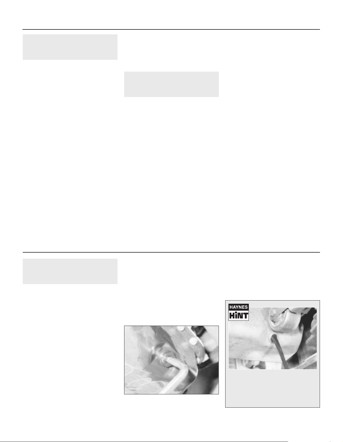
3 Position the draining container under the
drain plug, and unscrew the plug. On some
models, a square-section wrench may be
needed to slacken the plug (see illustration).
If possible, try to keep the plug pressed into
the sump while unscrewing it by hand the last
couple of turns (see Haynes Hint).
1•8 Maintenance procedures
3.3 Slackening the sump drain plug with a
square section wrench
Every 6000 miles or 6 months
Keep the drain plug pressed into the
sump while unscrewing it by hand the
last couple of turns. As the plug releases,
move it away sharply so that the stream
of oil issuing from the sump runs into the
container, not up your sleeve!
4 Allow the oil to drain into the container, and
check the condition of the plug’s sealing
washer; renew it if worn or damaged.
5 Allow some time for the old oil to drain,
noting that it may be necessary to reposition
the container as the oil flow slows to a trickle;
when the oil has completely drained, wipe
clean the drain plug and its threads in the
sump and refit the plug, tightening it securely.
6 If the filter is also to be renewed, move the
container into position under the oil filter,
which is located on the front side of the
cylinder block. On XV, XW and XY series
engines, place some rag around the filter
otherwise the oil that runs out as the filter is
unscrewed will make a mess all over the front
of the engine.
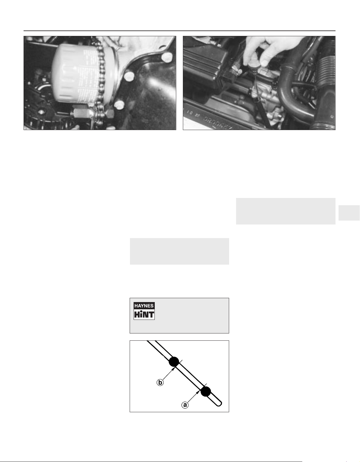
7 Using an oil filter removal tool if necessary,
slacken the filter initially, then unscrew it by
hand the rest of the way (see illustration).
Empty the oil in the old filter into the
container.
8 Use a clean rag to remove all oil, dirt and
sludge from the filter sealing area on the
engine. Check the old filter to make sure that
the rubber sealing ring hasn’t stuck to the
engine. If it has, carefully remove it.
9 Apply a light coating of clean engine oil to
the sealing ring on the new filter, then screw it
into position on the engine. Tighten the filter
firmly by hand only - do not use any tools.
10 Remove the old oil and all tools from
under the car, then lower the car to the
ground (if applicable).
11 Remove the dipstick, then unscrew the oil
filler cap from the rocker/cylinder head cover
or oil filler/breather neck (as applicable). Fill
the engine, using the correct grade and type
of oil (see “Lubricants and fluids, and
capacities”). An oil can spout or funnel may
help to reduce spillage. Pour in half the
specified quantity of oil first, then wait a few
minutes for the oil to fall to the sump.
Continue adding oil a small quantity at a time
until the level is up to the lower mark on the
dipstick. Adding approximately 1.5 litres will
bring the level up to the upper mark on the
dipstick. Refit the filler cap.
12 Start the engine and run it for a few
minutes; check for leaks around the oil filter
seal and the sump drain plug. Note that there
may be a delay of a few seconds before the oil
pressure warning light goes out when the
engine is first started, as the oil circulates
through the engine oil galleries and the new oil
filter (if fitted) before the pressure builds up.
13 Switch off the engine, and wait a few
minutes for the oil to settle in the sump once
more. With the new oil circulated and the filter
completely full, recheck the level on the
dipstick, and add more oil as necessary.
14 Dispose of the used engine oil safely, with
reference to “General repair procedures” in
the preliminary Sections of this manual.
4 Front brake pad check
1
1 Jack up the front of the vehicle, and
support it on axle stands (see “Jacking and
vehicle support”).
2 For better access to the brake calipers,
remove the roadwheels.
3 If any of the pads friction material is worn to
the specified thickness or less, all four pads
must be renewed as a set.
4 For a comprehensive check, the brake pads
should be removed and cleaned. The
operation of the caliper can then also be
checked, and the condition of the brake disc
itself can be fully examined on both sides.
Refer to Chapter 9 for further information.
5 Automatic transmission fluid
level check
1
1 Take the vehicle on a short journey, to
warm the transmission up to normal operating
temperature, then park the vehicle on level
ground. The fluid level is checked using the
dipstick located at the front of the engine
compartment, directly in front of the engine
(see illustration). The dipstick top is brightlycoloured for easy identification.
2 With the engine idling and the selector lever
in the “P” (Park) position, withdraw the
dipstick from the tube, and wipe all the fluid
from its end with a clean rag or paper towel.
Insert the clean dipstick back into the tube as
far as it will go, then withdraw it once more.
Note the fluid level on the end of the dipstick;
it should be between the upper and lower
marks (see illustration).
3 If topping-up is necessary, add the required
quantity of the specified fluid to the transmission
via the dipstick tube. Use a funnel with a finemesh gauze, to avoid spillage, and to ensure
that no foreign matter enters the transmission.
Note: Never overfill the transmission so that the
fluid level is above the upper mark.
4 After topping-up, take the vehicle on a short
run to distribute the fresh fluid, then recheck
the level again, topping-up if necessary.
5 Always maintain the level between the two
dipstick marks. If the level is allowed to fall
below the lower mark, fluid starvation may
result, which could lead to severe
transmission damage.
6 Frequent need for topping-up indicates that
there is a leak, which should be found and
corrected before it becomes serious.
Every 6000 miles or 6 months 1•9
1
5.2 Automatic fluid dipstick lower (a) and
upper (b) fluid level markings
For a quick check, the
thickness of the friction
material on each brake pad
can be measured through
the aperture in the caliper body
3.7 Using an oil filter removal tool to slacken the filter 5.1 Withdrawing the automatic transmission fluid dipstick
6 Underbonnet check for fluid
leaks and hose condition
1
Warning: Renewal of any air
conditioning hoses (where
fitted) must be left to a dealer
service department or air
conditioning specialist who has the
equipment to depressurise the system
safely. Never remove air conditioning
components or hoses until the system has
been depressurised.
General
1 High temperatures in the engine
compartment can cause the deterioration of
the rubber and plastic hoses used for engine,
accessory and emission systems operation.
Periodic inspection should be made for cracks,
loose clamps, material hardening and leaks.
2 Carefully check the large top and bottom
radiator hoses, along with the other smallerdiameter cooling system hoses and metal
pipes; do not forget the heater hoses/pipes
which run from the engine to the bulkhead.
Inspect each hose along its entire length,
replacing any that are cracked, swollen or
shows signs of deterioration. Cracks may
become more apparent if the hose is
squeezed (see Haynes Hint).
3 Make sure that all hose connections are
tight. If the spring clamps that are used to
secure some of the hoses appear to be
slackening, they should be renewed to
prevent the possibility of leaks.
4 Some other hoses are secured to their
fittings with screw type clips. Where screw
type clips are used, check to be sure they
haven’t slackened, allowing the hose to leak.
If clamps or screw type clips aren’t used,
make sure the hose has not expanded and/or
hardened where it slips over the fitting,
allowing it to leak.
5 Check all fluid reservoirs, filler caps, drain
plugs and fittings etc, looking for any signs of
leakage of oil, transmission and/or brake
hydraulic fluid, coolant and power steering
fluid. If the vehicle is regularly parked in the
same place, close inspection of the ground
underneath will soon show any leaks; ignore
the puddle of water which will be left if the air
conditioning system is in use. As soon as a
leak is detected, its source must be traced
and rectified. Where oil has been leaking for
some time, it is usually necessary to use a
steam cleaner, pressure washer or similar, to
clean away the accumulated dirt, so that the
exact source of the leak can be identified.
Vacuum hoses
6 It’s quite common for vacuum hoses,
especially those in the emissions system, to
be numbered or colour-coded, or to be
identified by coloured stripes moulded into
them. Various systems require hoses with
different wall thicknesses, collapse resistance
and temperature resistance. When renewing
hoses, be sure the new ones are made of the
same material.
7 Often the only effective way to check a
hose is to remove it completely from the
vehicle. If more than one hose is removed, be
sure to label the hoses and fittings to ensure
correct installation.
8 When checking vacuum hoses, be sure to
include any plastic T-fittings in the check.
Inspect the fittings for cracks, and check the
hose where it fits over the fitting for distortion,
which could cause leakage.
9 A small piece of vacuum hose can be used
as a stethoscope to detect vacuum leaks.
Hold one end of the hose to your ear, and
probe around vacuum hoses and fittings,
listening for the “hissing” sound characteristic
of a vacuum leak.
Warning: When probing with the
vacuum hose stethoscope, be
very careful not to come into
contact with moving engine
components such as the auxiliary drivebelt,
radiator electric cooling fan, etc.
Fuel hoses
Warning: Before carrying out the
following operation, refer to the
precautions given in “Safety
first!” at the beginning of this
manual, and follow them implicitly. Petrol
is a highly dangerous and volatile liquid,
and the precautions necessary when
handling it cannot be overstressed.
10 Check all fuel hoses for deterioration and
chafing. Check especially for cracks in areas
where the hose bends, and also just before
fittings, such as where a hose attaches to the
carburettor or fuel rail.
11 High-quality fuel line, usually identified by
the word “Fluoroelastomer” printed on the
hose, should be used for fuel line renewal.
Never, under any circumstances, use
unreinforced vacuum line, clear plastic tubing
or water hose for fuel lines.
12 Spring-type clamps are commonly used
on fuel lines. These clamps often lose their
tension over a period of time, and can be
“sprung” during removal. Replace all spring-
type clamps with screw clips whenever a hose
is replaced.
Metal lines
13 Sections of metal piping are often used
for fuel line between the fuel filter and the
engine. Check carefully to be sure the piping
has not been bent or crimped, and that cracks
have not started in the line.
14 If a section of metal fuel line must be
renewed, only seamless steel piping should
be used, since copper and aluminium piping
don’t have the strength necessary to
withstand normal engine vibration.
15 Check the metal brake lines where they
enter the master cylinder and ABS hydraulic
unit for cracks in the lines or loose fittings.
Any sign of brake fluid leakage calls for an
immediate and thorough inspection of the
brake system.
7 Spark plug renewal
2
1 The correct functioning of the spark plugs is
vital for the correct running and efficiency of
the engine. It is essential that the plugs fitted
are appropriate for the engine (a suitable type
is specified at the beginning of this Chapter). If
this type is used and the engine is in good
condition, the spark plugs should not need
attention between scheduled replacement
intervals. Spark plug cleaning is rarely
necessary, and should not be attempted unless
specialised equipment is available, as damage
can easily be caused to the firing ends.
2 If the marks on the original-equipment spark
plug (HT) leads cannot be seen, mark the leads
“1” to “4”, to correspond to the cylinder the lead
serves (No 1 cylinder is at the transmission end
of the engine). Pull the leads from the plugs by
gripping the end fitting, not the lead, otherwise
the lead connection may be fractured.
3 It is advisable to remove the dirt from the
spark plug recesses using a clean brush,
vacuum cleaner or compressed air before
removing the plugs, to prevent dirt dropping
into the cylinders.
4 Unscrew the plugs using a spark plug
spanner, suitable box spanner or a deep
socket and extension bar (see illustration).
1•10 Every 12 000 miles or 12 months
7.4 Tools required for spark plug removal,
gap adjustment and refitting
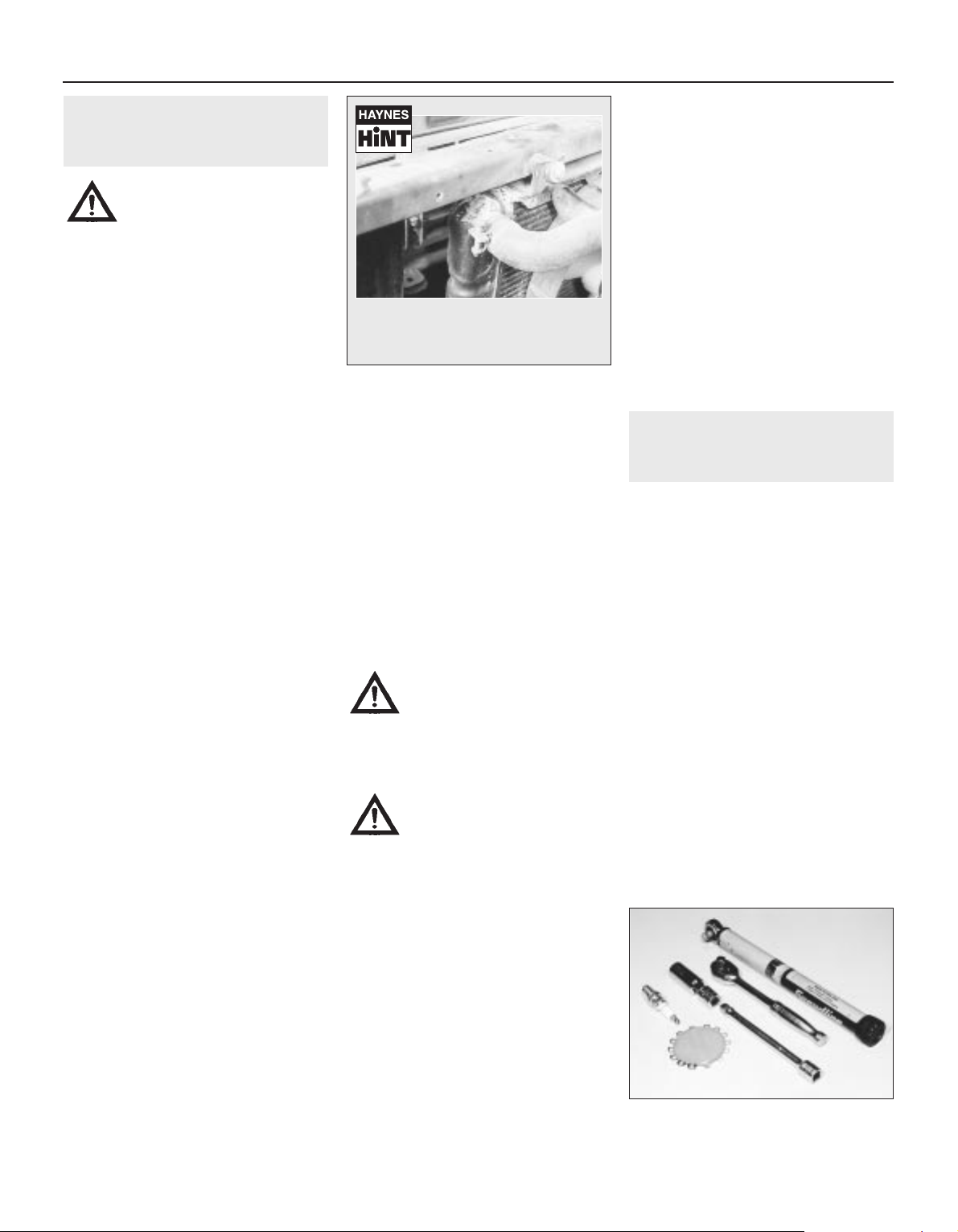
A leak in the cooling system will usually
show up as white or rust-coloured
deposits on the area adjoining the leak
Keep the socket aligned with the spark plug if it is forcibly moved to one side, the ceramic
insulator may be broken off. As each plug is
removed, examine it as follows.
5 Examination of the spark plugs will give a
good indication of the condition of the engine.
If the insulator nose of the spark plug is clean
and white, with no deposits, this is indicative
of a weak mixture or too hot a plug (a hot plug
transfers heat away from the electrode slowly,
a cold plug transfers heat away quickly).
6 If the tip and insulator nose are covered
with hard black-looking deposits, then this is
indicative that the mixture is too rich. Should
the plug be black and oily, then it is likely that
the engine is fairly worn, as well as the mixture
being too rich.
7 If the insulator nose is covered with light tan
to greyish-brown deposits, then the mixture is
correct and it is likely that the engine is in
good condition.
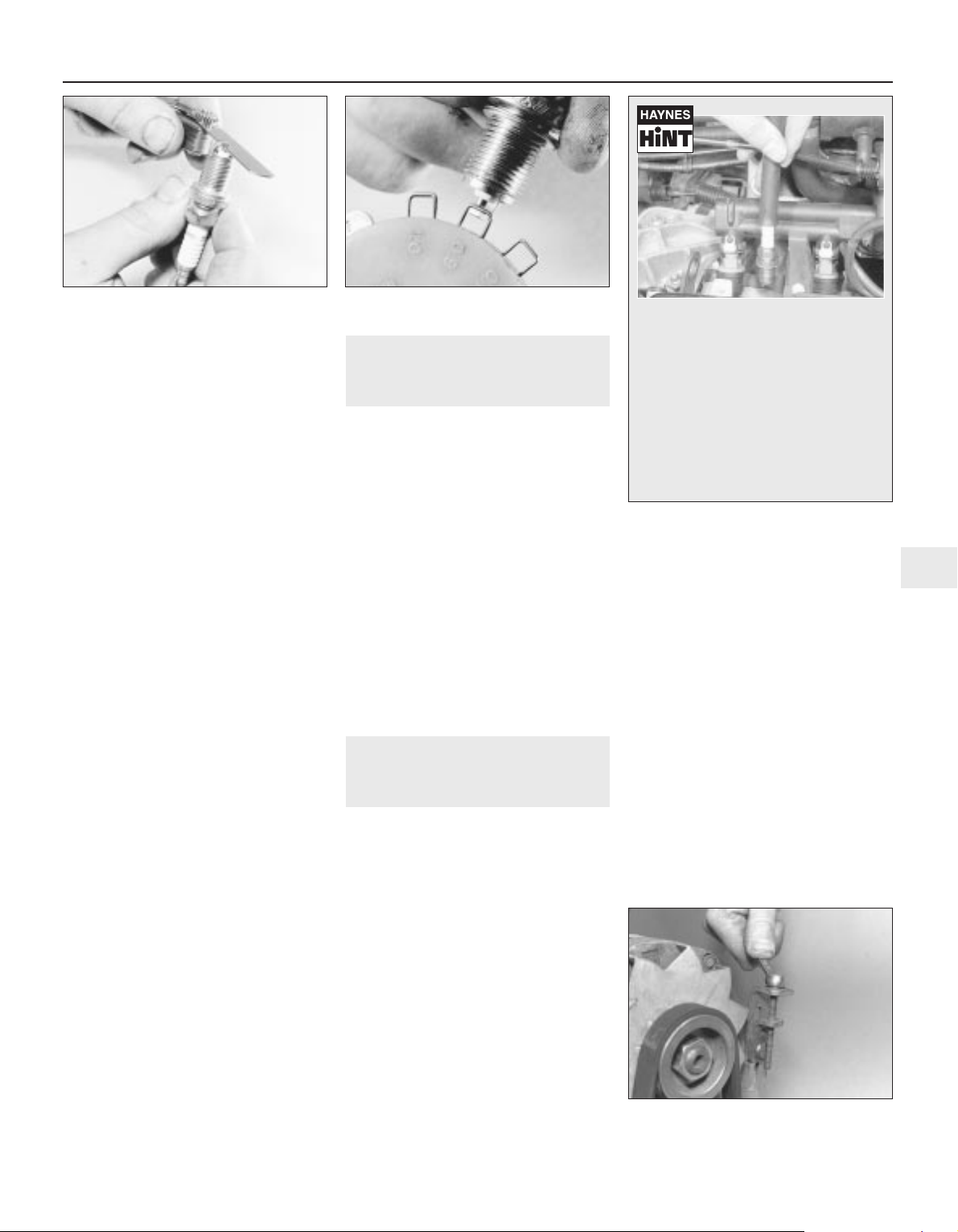
8 The spark plug electrode gap is of
considerable importance as, if it is too large or
too small, the size of the spark and its
efficiency will be seriously impaired. The gap
should be set to the value given in the
Specifications at the beginning of this Chapter.
9 To set the gap, measure it with a feeler
blade, and then bend open, or closed, the
outer plug electrode until the correct gap is
achieved (see illustration). The centre
electrode should never be bent, as this may
crack the insulator and cause plug failure, if
nothing worse. If using feeler blades, the gap
is correct when the appropriate-size blade is a
firm sliding fit.
10 Special spark plug electrode gap
adjusting tools are available from most motor
accessory shops, or from some spark plug
manufacturers (see illustration).
11 Before fitting the spark plugs, check that
the threaded connector sleeves are tight, and
that the plug exterior surfaces and threads are
clean (see Haynes Hint).
12 Remove the rubber hose (if used), and
tighten the plug to the specified torque using
the spark plug socket and a torque wrench.
Refit the remaining spark plugs in the same
manner.
13 Connect the HT leads in their correct
order, and refit any components removed for
access.
8 Throttle and choke cable
lubrication and adjustment
1
1 The throttle cable is connected to a
spring-loaded reel which pivots on the face of
the cylinder head. On certain models, the reel
then operates the throttle lever on the
carburettor through a plastic balljointed
control rod.
2 Sparingly apply a few drops of light oil to
the throttle spindles, linkage pivot points and
to the cable itself. Similarly lubricate the
exposed ends of the choke cable (where
fitted).
3 Check that there is a small amount of
slackness in the cable so that the throttle
linkage closes fully with the accelerator pedal
released. Also check that full throttle can be
obtained with the accelerator pedal fully
depressed.
4 If there is any doubt about the cable
adjustment, refer to the relevant Parts of
Chapter 4 for the full adjustment procedure.
9 Auxiliary drivebelt check and
renewal
2
1 Depending on specification, either one or
two auxiliary drivebelts are fitted. Where two
belts are fitted, it will obviously be necessary
to remove the outer belt in order to renew the
inner belt.
Checking the auxiliary drivebelt
condition
2 Apply the handbrake, then jack up the front
of the car and support it on axle stands.
Remove the right-hand front roadwheel.
3 From underneath the front of the car, prise
out the retaining clips, and remove the plastic
cover from the wing valance where necessary,
to gain access to the crankshaft
sprocket/pulley bolt.
4 Using a suitable socket and extension bar
fitted to the crankshaft sprocket/pulley bolt,
rotate the crankshaft so that the entire length
of the drivebelt(s) can be examined. Examine
the drivebelt(s) for cracks, splitting, fraying or
damage. Check also for signs of glazing (shiny
patches) and for separation of the belt plies.
Renew the belt if worn or damaged.
5 If the condition of the belt is satisfactory,
check the drivebelt tension as described below.
Auxiliary drivebelt - removal,
refitting and tensioning
Removal
6 If not already done, proceed as described
in paragraphs 2 and 3.
7 Disconnect the battery negative lead.
8 Slacken both the alternator upper and lower
mounting nuts/bolts (as applicable).
9 Push the alternator toward the engine until
the belt is slack then slip the drivebelt from
the pulleys. Where an adjuster bolt is fitted,
back off the adjuster to relieve the tension in
the drivebelt, then slip off the belt (see
illustration).
Refitting
10 If the belt is being renewed, ensure that
the correct type is used. Fit the belt around
the pulleys, and take up the slack in the belt
Every 12 000 miles or 12 months 1•11
1
7.9 Measuring the spark plug gap with a
feeler blade
7.10 Measuring the spark plug gap with a
wire gauge
9.9 Slackening the alternator adjuster bolt
to release the auxiliary drivebelt
It is very often difficult to insert spark
plugs into their holes without crossthreading them. To avoid this
possibility, fit a short length of 5/16 inch
internal diameter rubber hose over the
end of the spark plug. The flexible hose
acts as a universal joint to help align
the plug with the plug hole. Should the
plug begin to cross-thread, the hose
will slip on the spark plug, preventing
thread damage to the aluminium
cylinder head

by moving the alternator by hand, or
tightening the adjuster bolt.
11 Tension the drivebelt as described in the
following paragraphs.
Tensioning
12 If not already done, proceed as described
in paragraphs 2 and 3.
13 Correct tensioning of the drivebelt will
ensure that it has a long life. A belt which is
too slack will slip and perhaps squeal.
Beware, however, of overtightening, as this
can cause wear in the alternator bearings.
14 The belt should be tensioned so that,
under firm thumb pressure, there is
approximately 5.0 mm of free movement at
the mid-point between the pulleys on the
longest belt run.
15 To adjust, with the upper mounting
nut/bolt just holding the alternator firm, and
the lower mounting nut/bolt loosened, lever
the alternator away from the engine, or turn
the adjuster bolt until the correct tension is
achieved. Rotate the crankshaft a couple of
times, recheck the tension, then securely
tighten both the alternator mounting
nuts/bolts. Where applicable, also tighten the
bolt securing the adjuster strap to its
mounting bracket.
16 Reconnect the battery negative lead.
17 Refit the plastic cover to the wing valance.
Refit the roadwheel, and lower the vehicle to
the ground.
10 Clutch pedal stroke
adjustment
1
1 The clutch pedal stroke adjustment is
checked by measuring the clutch pedal travel.
Before doing this, settle the cable by
depressing and releasing it a few times.
2 Ensure that there are no obstructions
beneath the clutch pedal then measure the
distance from the centre of the clutch pedal
pad to the base of the steering wheel with the
pedal in the at-rest position. Depress the
clutch pedal fully to the floor, and measure the
distance from the centre of the clutch pedal
pad to the base of the steering wheel (see
illustration).
3 Subtract the first measurement from the
second to obtain the clutch pedal travel. If this
is not with the range given in the
Specifications at the start of this Chapter,
adjust the clutch as follows.
4 On models fitted with the BH3
transmission, loosen the locknut and turn the
adjuster on the transmission intermediate
lever pushrod as necessary. On all other
models, slacken the locknut and turn the
adjuster nut on the end of the cable.
5 Check the pedal stroke again and make
further adjustments as necessary. When all is
correct, tighten the relevant locknut.
11 Seat belt check
1
Check the seat belts for satisfactory
operation and condition. Inspect the webbing
for fraying and cuts. Check that they retract
smoothly and without binding into their reels.
Check the seat belt mountings, ensuring
that all the bolts are securely tightened.
12 Lock and hinge check and
lubrication
1
1 Check that the doors, bonnet and tailgate
close securely. Check that the bonnet safety
catch operates correctly. Check the operation
of the door check straps.
2 Lubricate the hinges, door check straps,
the striker plates and the bonnet catch
sparingly with a little oil or grease.
3 If any of the doors, bonnet or tailgate/boot
lid do not close effectively or appear not to be
flush with the surrounding panels, carry out
the relevant adjustment procedures contained
in Chapter 11.
13 Rear brake shoe check -
models with rear drum brakes
3
Remove the rear brake drums, and check the
brake shoes for signs of wear or contamination.
At the same time, also inspect the wheel
cylinders for signs of leakage, and the brake
drum for signs of wear. Refer to the relevant
Sections of Chapter 9 for further information.
14 Rear brake pad condition
check - models with rear disc
brakes
1
1 Chock the front wheels, then jack up the
rear of the vehicle and support it on axle
stands (see “Jacking and vehicle support”).
Remove the rear roadwheels.
2 For a quick check, the thickness of friction
material remaining on each brake pad can be
measured through the top of the caliper body.
If any pad’s friction material is worn to the
specified thickness or less, all four pads must
be renewed as a set.
3 For a comprehensive check, the brake pads
should be removed and cleaned. This will
permit the operation of the caliper to be
checked, and the condition of the brake disc
itself to be fully examined on both sides. Refer
to Chapter 9 for further information.
15 Handbrake check and
adjustment
2
Refer to Chapter 9.
16 Underbody and fuel/brake
line check
1
1 With the vehicle raised and supported on
axle stands (see “Jacking and vehicle
support”), or over an inspection pit,
thoroughly inspect the underbody and wheel
arches for signs of damage and corrosion. In
particular, examine the bottom of the side
sills, and any concealed areas where mud can
collect. Where corrosion and rust is evident,
press and tap firmly on the panel with a
screwdriver, and check for any serious
corrosion which would necessitate repairs. If
the panel is not seriously corroded, clean
away the rust, and apply a new coating of
underseal. Refer to Chapter 11 for more
details of body repairs.
2 At the same time, inspect the treated lower
body panels for stone damage and general
condition.
3 Inspect all of the fuel and brake lines on the
underbody for damage, rust, corrosion and
leakage. Also make sure that they are
correctly supported in their clips. Where
applicable, check the PVC coating on the
lines for damage.
4 Inspect the flexible brake hoses in the
vicinity of the calipers, where they are
subjected to most movement. Bend them
between the fingers (but do not actually bend
them double, or the casing may be damaged)
and check that this does not reveal
previously-hidden cracks, cuts or splits.
17 Exhaust system check
1
1 With the engine cold (at least three hours
after the vehicle has been driven), check the
complete exhaust system, from its starting
point at the engine to the end of the tailpipe.
Ideally, this should be done on a hoist, where
unrestricted access is available; if a hoist is not
available, raise and support the vehicle on axle
stands (see “Jacking and vehicle support”).
1•12 Every 12 000 miles or 12 months
10.2 To check the clutch pedal stroke,
measure the clutch pedal travel as
described in the text
2 Check the pipes and connections for
evidence of leaks, severe corrosion, or
damage. Make sure that all brackets and
rubber mountings are in good condition, and
tight; if any of the mountings are to be
renewed, ensure that the replacements are of
the correct type. Leakage at any of the joints
or in other parts of the system will usually
show up as a black sooty stain in the vicinity
of the leak.
3 At the same time, inspect the underside of
the body for holes, corrosion, open seams,
etc. which may allow exhaust gases to enter
the passenger compartment. Seal all body
openings with silicone or body putty.
4 Rattles and other noises can often be
traced to the exhaust system, especially the
rubber mountings. Try to move the system,
silencer(s) and catalytic converter. If any
components can touch the body or
suspension parts, secure the exhaust system
with new mountings.
18 Bodywork, paint and exterior
trim check
1
1 The best time to carry out this check is after
the car has been washed so that any surface
blemish or scratch will be clearly evident and
not hidden by a film of dirt.
2 Starting at one front corner check the
paintwork all around the car, looking for minor
scratches or more serious dents. Check all
the trim and make sure that it is securely
attached over its entire length.
3 Check the security of all door locks, door
mirrors, badges, bumpers, radiator grille and
wheel trim. Anything found loose, or in need
of further attention should be done with
reference to the relevant Chapters of this
manual.
4 Rectify any problems noticed with the
paintwork or body panels as described in
Chapter 11.
19 Headlight beam alignment
check
1
Accurate adjustment of the headlight beam
is only possible using optical beam-setting
setting equipment, and this work should
therefore be carried out by a Peugeot dealer
or service station with the necessary facilities.
Basic adjustments can be carried out in an
emergency, and further details are given in
Chapter 12.
20 Air conditioning system
check
1
Warning: The air conditioning
system is under high pressure.
Do not loosen any fittings or
remove any components until
after the system has been discharged. Air
conditioning refrigerant must be properly
discharged into an approved type of
container, at a dealer service department
or an automotive air conditioning repair
facility capable of handling the refrigerant
safely. Always wear eye protection when
disconnecting air conditioning system
fittings.
1 The following maintenance checks should
be performed on a regular basis, to ensure
that the system continues to operate at peak
efficiency:
a) Check the auxiliary drivebelt. If it’s worn
or deteriorated, renew it.
b) Check the system hoses. Look for cracks,
bubbles, hard spots and deterioration.
Inspect the hoses and all fittings for oil
bubbles and seepage. If there’s any
evidence of wear, damage or leaks, renew
the hose(s).
c) Inspect the condenser fins for leaves,
insects and other debris. Use a “fin
comb” or compressed air to clean the
condenser.
Warning: Wear eye protection
when using compressed air!
d) Check that the drain tube from the front
of the evaporator is clear - note that it is
normal to have clear fluid (water) dripping
from this while the system is in operation,
to the extent that quite a large puddle can
be left under the vehicle when it is parked.
2 It’s a good idea to operate the system for
about 30 minutes at least once a month,
particularly during the winter. Long term
non-use can cause hardening, and
subsequent failure, of the seals.
3 Because of the complexity of the air
conditioning system and the special
equipment necessary to service it, in-depth
repairs are not included in this manual, apart
from those procedures covered in Chapter 3.
4 The most common cause of poor cooling is
simply a low system refrigerant charge. If a
noticeable drop in cool air output occurs, the
following quick check will help you determine
if the refrigerant level is low.
5 Warm the engine up to normal operating
temperature.
6 Place the air conditioning temperature
selector at the coldest setting, and put the
blower at the highest setting. Open the doors
- to make sure the air conditioning system
doesn’t cycle off as soon as it cools the
passenger compartment.
7 With the compressor engaged - the clutch
will make an audible click, and the centre of
the clutch will rotate - feel the inlet and outlet
pipes at the compressor. One side should be
cold, and one hot. If there’s no perceptible
difference between the two pipes, there’s
something wrong with the compressor or the
system. It might be a low charge - it might be
something else. Take the vehicle to a dealer
service department or an automotive air
conditioning specialist.
21 Manual transmission oil level
check
2
Note: The following procedure is only
applicable to models produced after
approximately October 1986. There is no
provision on the transmission for fluid level
checking on earlier transmissions (see Chapter
7A). Suitable square-section wrench may be
required to undo the transmission filler/level
plug on some models. These wrenches can be
obtained from most motor factors or your
Peugeot dealer.
1 Park the car on a level surface. The oil level
must be checked before the car is driven, or
at least 5 minutes after the engine has been
switched off. If the oil is checked immediately
after driving the car, some of the oil will
remain distributed around the transmission
components, resulting in an inaccurate level
reading.
2 Prise out the retaining clips and remove the
access cover from the left-hand wheelarch
liner.
3 Wipe clean the area around the filler/level
plug, which is situated on the left-hand end of
the transmission (see illustration). Unscrew
the plug and clean it; discard the sealing
washer.
Every 12 000 miles or 12 months 1•13
1
21.3 Using a square section wrench to
unscrew the transmission filler/level plug
(MA transmission shown)
Every 24 000 miles or 2 years
4 The oil level should reach the lower edge of
the filler/level hole. A certain amount of oil will
have gathered behind the filler/level plug, and
will trickle out when it is removed; this does
not necessarily indicate that the level is
correct. To ensure that a true level is
established, wait until the initial trickle has
stopped, then add oil as necessary until a
trickle of new oil can be seen emerging (see
illustration). The level will be correct when
the flow ceases; use only good-quality oil of
the specified type (refer to “Lubricants, fluids
and capacities”).
5 Filling the transmission with oil is an
extremely awkward operation; above all, allow
plenty of time for the oil level to settle properly
before checking it. If a large amount is added
to the transmission, and a large amount flows
out on checking the level, refit the filler/level
plug and take the vehicle on a short journey
so that the new oil is distributed fully around
the transmission components, then recheck
the level when it has settled again.
6 If the transmission has been overfilled so
that oil flows out as soon as the filler/level
plug is removed, check that the car is
completely level (front-to-rear and side-toside), and allow the surplus to drain off into a
suitable container.
7 When the level is correct, fit a new sealing
washer to the filler/level plug. Refit the plug,
tightening it to the specified torque wrench
setting. Wash off any spilt oil then refit the
access cover securing it in position with the
retaining clips.
22 Manual transmission oil
renewal
3
This service requirement is only applicable
to pre-1988 BE1 transmissions. Refer to the
procedures contained in Chapter 7A.
23 Automatic transmission fluid
renewal
2
1 Take the vehicle on a short run, to warm the
transmission up to normal operating
temperature.
2 Park the car on level ground, then switch off
the ignition and apply the handbrake firmly.
For improved access, jack up the front of the
car and support it securely on axle stands.
Note that, when refilling and checking the fluid
level, the car must be lowered to the ground,
and level, to ensure accuracy.
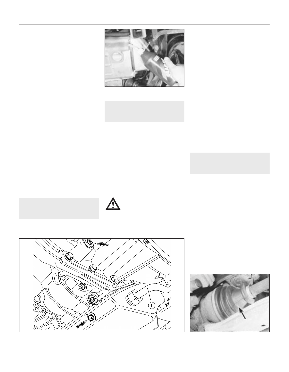
3 Remove the dipstick, then position a
suitable container under the transmission. The
transmission has two drain plugs: one on the
sump, and another on the bottom of the
differential housing (see illustration).
Warning: If the fluid is hot, take
precautions against scalding.
4 Unscrew both drain plugs, and allow the
fluid to drain completely into the container.
Clean the drain plugs, being especially careful
to wipe any metallic particles off the magnetic
insert. Discard the original sealing washers;
these should be renewed whenever they are
disturbed.
5 When the fluid has finished draining, clean
the drain plug threads and those of the
transmission casing. Fit a new sealing washer
to each drain plug, and refit the plugs to the
transmission, tightening each securely. If the
car was raised for the draining operation, now
lower it to the ground. Make sure that the car
is level (front-to-rear and side-to-side).
6 Refilling the transmission is an awkward
operation, adding the specified type of fluid to
the transmission a little at a time via the
dipstick tube. Use a funnel with a fine-mesh
gauze, to avoid spillage, and to ensure that no
foreign matter enters the transmission. Allow
plenty of time for the fluid level to settle
properly.
7 Once the level is up to the “MAX” mark on
the dipstick, refit the dipstick. Start the
engine, and allow it to idle for a few minutes.
Switch the engine off, then recheck the level,
topping-up if necessary. Take the car on a
short run to fully distribute the new fluid
around the transmission, then recheck the
fluid level as described in Section 5.
24 Driveshaft bellows check
1
With the vehicle raised and securely
supported on stands (see “Jacking and
vehicle support”), turn the steering onto full
lock, then slowly rotate the roadwheel.
Inspect the condition of the outer constant
velocity (CV) joint rubber bellows, squeezing
the bellows to open out the folds (see
illustration). Check for signs of cracking,
splits or deterioration of the rubber, which
may allow the grease to escape, and lead to
water and grit entry into the joint. Also check
the security and condition of the retaining
clips. Repeat these checks on the inner CV
joints. If any damage or deterioration is found,
the bellows should be renewed as described
in Chapter 8.
At the same time, check the general
condition of the CV joints themselves by first
holding the driveshaft and attempting to
rotate the wheel. Repeat this check by holding
1•14 Every 24 000 miles or 2 years
21.4 Topping-up the transmission oil level
23.3 Automatic transmission fluid drain plugs (arrowed). Transmission is refilled via the
dipstick tube (1)
24.1 Check the condition of the driveshaft
bellows (arrowed)
the inner joint and attempting to rotate the
driveshaft. Any appreciable movement
indicates wear in the joints, wear in the
driveshaft splines, or a loose driveshaft
retaining nut.
25 Steering and suspension
check
2
Front suspension and steering
check
1 Apply the handbrake then jack up the front
of the vehicle and support it on axle stands
(see “Jacking and vehicle support”).
2 Visually inspect the balljoint dust covers and
the steering gear bellows for splits, chafing or
deterioration. Any wear of these components
will cause loss of lubricant, together with dirt
and water entry, resulting in rapid deterioration
of the balljoints or steering gear.
3 Check the power steering fluid hoses
(where applicable) for chafing or deterioration,
and the pipe and hose unions for fluid leaks.
Also check for signs of fluid leakage under
pressure from the steering gear rubber
bellows, which would indicate failed fluid
seals within the steering gear.
4 Check for signs of fluid leakage around the
suspension strut body, or from the rubber
boot around the piston rod (where fitted).
Should any fluid be noticed, the shock
absorber is defective internally, and renewal is
necessary.
5 Grasp the roadwheel at the 12 o’clock and
6 o’clock positions, and try to rock it (see
illustration). Very slight free play may be felt,
but if the movement is appreciable, further
investigation is necessary to determine the
source. Continue rocking the wheel while an
assistant depresses the footbrake. If the
movement is now eliminated or significantly
reduced, it is likely that the wheel bearings are
at fault. If the free play is still evident with the
footbrake depressed, then there is wear in the
suspension joints or mountings.
6 Now grasp the wheel at the 9 o’clock and 3
o’clock positions, and try to rock it as before.
Any movement felt now may again be caused
by wear in the wheel bearings or the steering
track rod end balljoints. If the outer track rod
end is worn, the visual movement will be
obvious. If the inner joint is suspect, it can be
felt by placing a hand over the rack-and-pinion
rubber bellows, and gripping the track rod. If
the wheel is now rocked, movement will be felt
at the inner joint if wear has taken place.
7 Using a large screwdriver or flat bar, check
for wear in the suspension mounting bushes
by levering between the relevant suspension
component and its attachment point. Some
movement is to be expected as the mountings
are made of rubber, but excessive wear
should be obvious. Also check the condition
of any visible rubber bushes, looking for splits,
cracks or contamination of the rubber.
8 With the vehicle standing on its wheels,
have an assistant turn the steering wheel
back-and-forth, about an eighth of a turn each
way. There should be very little, if any, lost
movement between the steering wheel and
roadwheels. If this is not the case, closely
observe the joints and mountings previously
described, but in addition, check the steering
column universal joints for wear, and also
check the rack-and-pinion steering gear itself.
9 The efficiency of the shock absorber may
be checked by bouncing the car at each front
corner. Generally speaking, the body will
return to its normal position and stop after
being depressed. If it rises and returns on a
rebound, the shock absorber is probably
suspect. Examine also the shock absorber
upper and lower mountings for any signs of
wear or fluid leakage.
Rear suspension check
10 Chock the front wheels, then raise the rear
of the vehicle and support it on axle stands.
(see “Jacking and vehicle support”).
11 Check the rear hub bearings for wear,
using the method described for the front hub
bearings (paragraph 4).
12 Using a large screwdriver or flat bar,
check for wear in the suspension mounting
bushes by levering between the relevant
suspension component and its attachment
point. Some movement is to be expected as
the mountings are made of rubber, but
excessive wear should be obvious. Check the
condition of the shock absorbers as
described previously.
26 Air cleaner filter element
renewal
1
XV, XW and XY series engines
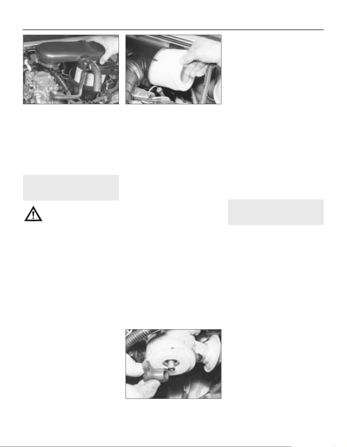
1 Unscrew the wing nut on the air cleaner
casing end-face (see illustration).
2 Withdraw the end cover with element (see
illustration).
3 Discard the element and wipe the casing
interior clean.
4 Fit the new element and the cover, tighten
the wing nut.
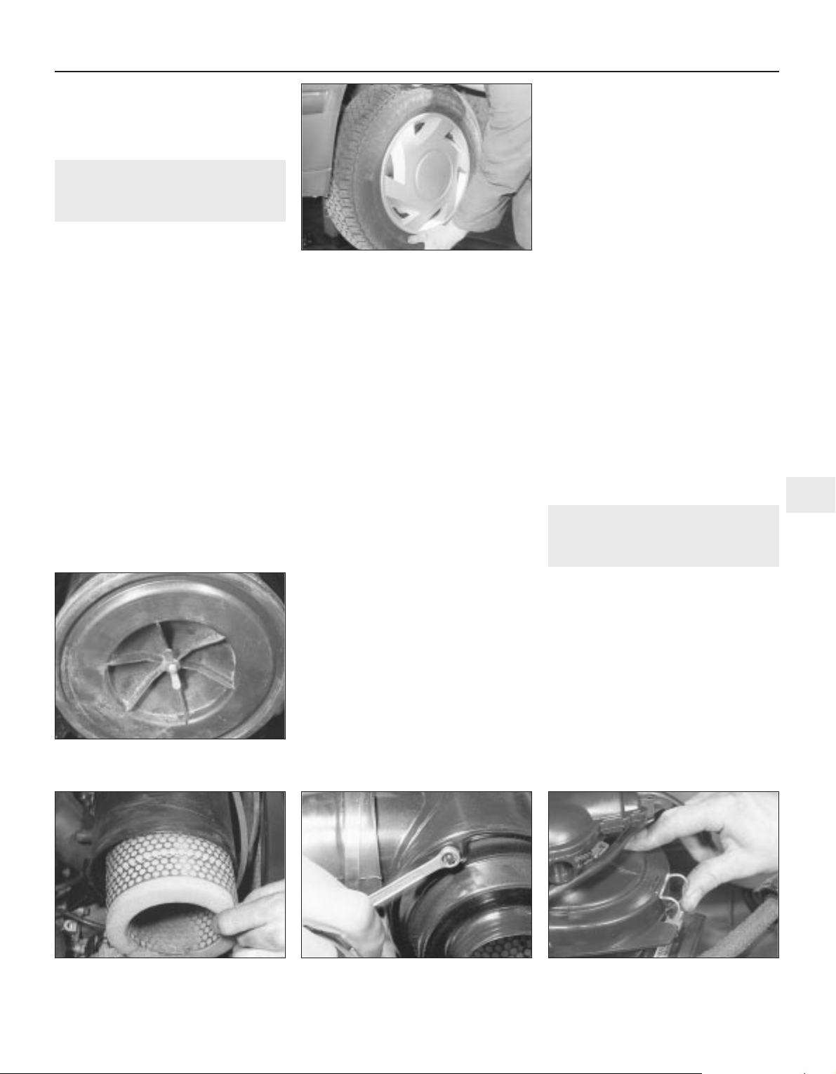
XU and TU series engines
4 Disconnect the air duct from the end of the
air cleaner.
5 Unscrew the nuts and remove the end (or
top) cover (see illustrations). On some types
Every 24 000 miles or 2 years 1•15
1
25.5 Check for wear in the hub bearings
by grasping the wheel and trying to rock it
26.1 On XV, XW and XY series engines,
unscrew the wing nut on the air cleaner
cover . . .
26.2 . . . and remove the cover and filter
element
26.5a On XU and TU series engines,
unscrew the nuts . . .
26.5b . . . or release the spring clips . . .
of air cleaner, the end (or top) cover is
retained by a number of spring clips.
6 Extract the element (see illustration).
7 Discard the element and wipe the casing
interior clean.
8 Insert the new element then refit the end
cover and air duct. Ensure that the cover is
correctly seated, to prevent air leaks, before
fastening with the nuts or the clips.
27 Ignition system check
1
Warning: Voltages produced by
an electronic ignition system are
considerably higher than those
produced by conventional
ignition systems. Extreme care must be
taken when working on the system with
the ignition switched on. Persons with
surgically-implanted cardiac pacemaker
devices should keep well clear of the
ignition circuits, components and test
equipment.
1 The ignition system components should be
checked for damage or deterioration as
described under the relevant sub-heading.
Carburettor models
General component check
2 The spark plug (HT) leads should be
checked whenever new spark plugs are fitted.
3 Ensure that the leads are numbered before
removing them, to avoid confusion when
refitting (see Section 27). Pull the leads from
the plugs by gripping the end fitting, not the
lead, otherwise the lead connection may be
fractured.
4 Check inside the end fitting for signs of
corrosion, which will look like a white crusty
powder. Push the end fitting back onto the
spark plug, ensuring that it is a tight fit on the
plug. If not, remove the lead again and use
pliers to carefully crimp the metal connector
inside the end fitting until it fits securely on the
end of the spark plug.
5 Using a clean rag, wipe the entire length of
the lead to remove any built-up dirt and
grease. Once the lead is clean, check for
burns, cracks and other damage. Do not bend
the lead excessively, nor pull the lead
lengthways - the conductor inside might
break.
6 Disconnect the other end of the lead from
the distributor cap. Again, pull only on the end
fitting. Check for corrosion and a tight fit in the
same manner as the spark plug end. If an
ohmmeter is available, check the resistance of
the lead by connecting the meter between the
spark plug end of the lead and the segment
inside the distributor cap. Refit the lead
securely on completion.
7 Check the remaining leads one at a time, in
the same way.
8 If new spark plug (HT) leads are required,
purchase a set for your specific car and
engine.
9 Release the clips or unscrew its retaining
screws and remove the distributor cap. Wipe
it clean, and carefully inspect it inside and out
for signs of cracks, black carbon tracks
(tracking) and worn, burned or loose contacts;
check that the cap’s carbon brush is unworn,
free to move against spring pressure, and
making good contact with the rotor arm. Also
inspect the cap seal for signs of wear or
damage, and renew if necessary. Remove the
rotor arm from the distributor shaft and
inspect the rotor arm (see illustration). It is
common practice to renew the cap and rotor
arm whenever new spark plug (HT) leads are
fitted. When fitting a new cap, remove the
leads from the old cap one at a time, and fit
them to the new cap in the exact same
location - do not simultaneously remove all
the leads from the old cap, or firing order
confusion may occur. When refitting, ensure
that the arm is securely pressed onto the
shaft, and tighten the cap retaining screws
securely.
10 Even with the ignition system in first-class
condition, some engines may still occasionally
experience poor starting attributable to damp
ignition components. To disperse moisture, a
water-dispersant aerosol can be very
effective.
Ignition timing - check and
adjustment
11 Check the ignition timing as described in
Chapter 5B.
Fuel-injected models
General component check
12 On single-point fuel injection models,
carry out the checks described above in
paragraphs 3 to 8 noting that on some
models the HT leads are removed from the
ignition module, not the distributor cap. On
multi-point fuel injection models, carry out
the checks described above in paragraphs 3
to 10.
Ignition timing - check and
adjustment
13 Refer to Chapter 5B.
28 Idle speed and mixture
check and adjustment
3
1 Before checking the idle speed and mixture
setting, always check the following first:
a) Check the ignition timing (Chapter 5B).
b) Check that the spark plugs are in good
condition and correctly gapped (Section 7).
c) Check that the throttle cable and, on
carburettor models, the choke cable
(where fitted) is correctly adjusted
(Section 8 and Chapter 4A, 4B or 4C).
d) Check that the crankcase breather hoses
are secure, with no leaks or kinks (Section 29).
e) Check that the air cleaner filter element is
clean (Section 26).
f) Check that the exhaust system is in good
condition (Chapter 4D).
g) If the engine is running very roughly,
check the compression pressures and
valve clearances as described in Chapter
2A, 2B or 2C.
2 Take the car on a journey of sufficient
length to warm it up to normal operating
temperature. Proceed as described under the
relevant sub-heading. Note: Adjustment
should be completed within two minutes of
return, without stopping the engine. If this
cannot be achieved, or if the radiator electric
cooling fan operates, first wait for the cooling
fan to stop. Clear any excess fuel from the
inlet manifold by racing the engine two or
three times to between 2000 and 3000 rpm,
then allow it to idle again.
1•16 Every 24 000 miles or 2 years
26.5c . . . then lift off the top, or end cover 26.6 With the cover removed, withdraw
the filter element
27.9 Remove the rotor arm from the
distributor for inspection
Carburettor models
Idle speed adjustment - single
carburettor engines
3 Ensure that all electrical loads are switched
off and, where applicable, the choke is
pushed fully in; if the car does not have a
tachometer (rev counter), connect one to the
engine, following its manufacturer’s
instructions. Note the idle speed, and
compare it with that specified.
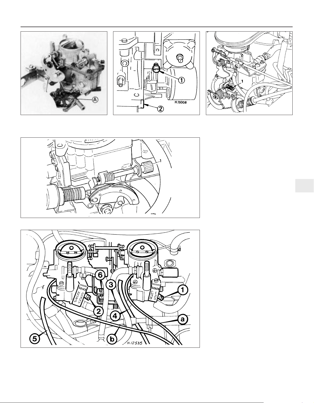
4 The idle speed adjusting screw is situated
in various locations according to carburettor
type (see illustrations). It may be necessary
to remove a retaining clip and plastic cover to
gain access to the carburettor. Using a
suitable flat-bladed screwdriver, turn the idle
speed screw in or out as necessary to obtain
the specified idling speed as given in the
Specifications.
5 If the idle mixture CO content is not to be
adjusted, switch off the engine, disconnect
any instruments and refit all disturbed
components.
Idle speed adjustment - twin
carburettor engines
6 On twin carburettor installations, it is
necessary to balance the carburettors so that
the airflow through both is the same before
adjusting the idling speed. To do this a
vacuum gauge or carburettor synchronising
tool will be required.
7 Ensure that all electrical loads are switched
off and, where applicable, the choke is
pushed fully in; if the car does not have a
tachometer (rev counter), connect one to the
engine, following its manufacturer’s
instructions. Note the idle speed, and
compare it with that specified.
8 Remove the air cleaner assembly as
described in Chapter 4A.
9 If a vacuum gauge is being used,
disconnect the vacuum pipe and connect the
gauge to the vacuum pipe stub on the lefthand carburettor (see illustrations).
Every 24 000 miles or 2 years 1•17
1
28.4a Typical idle speed adjusting screw
location (A) on the Solex PBISA
carburettors
28.4b Idle speed adjusting screw (1) and
mixture screw (2) location on the
Solex 32-34 Z2 carburettors
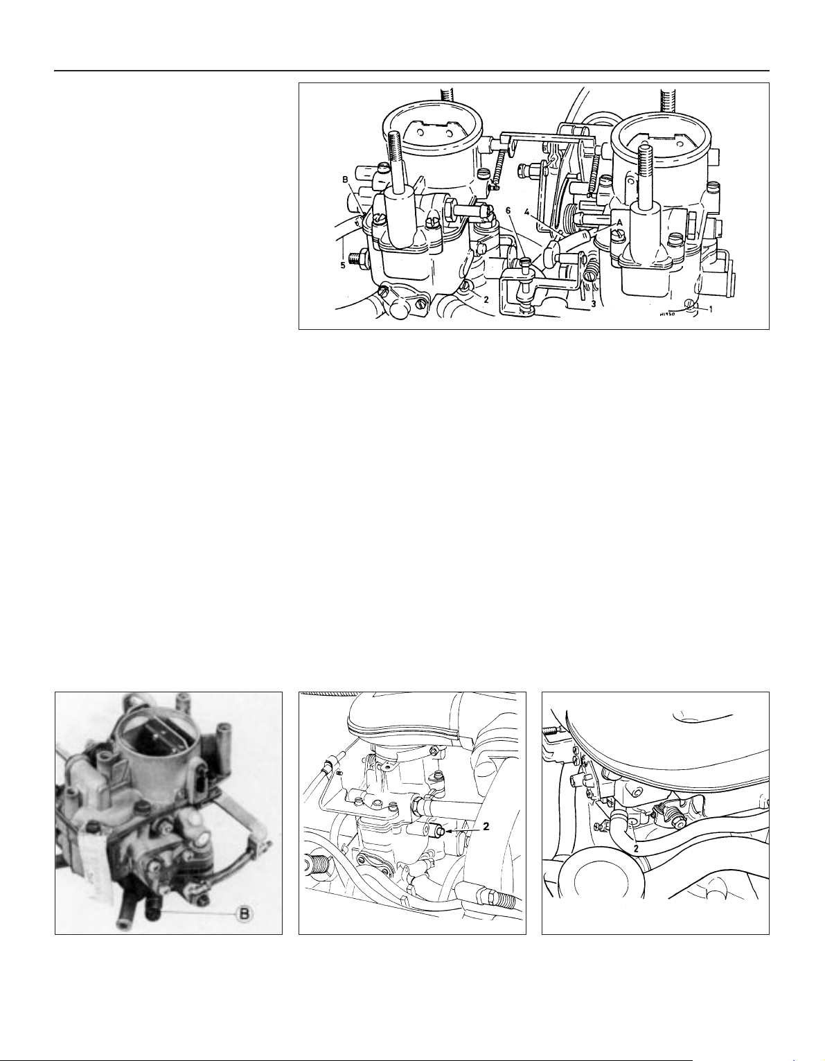
28.4c Idle speed adjusting screw location
(1) on the Weber 32 IBSH carburettors
28.4d Idle speed adjusting screw location (1) on the Weber 36 TLC carburettors
28.9a Adjustment points on the Solex twin carburettor installation
1 Mixture screw
2 Mixture screw
3 Idle speed screw
4 Vacuum pipe
5 Vacuum pipe
6 Synchronising screw
a Vacuum gauge pipe
b Vacuum gauge pipe
10 With the engine idling, turn the idle speed
screw on the interconnecting linkage as
necessary until the engine speed is 1000 rpm.
11 Note the reading on the vacuum gage,
then transfer the gauge pipe to the vacuum
pipe stub on the right-hand carburettor. If the
reading is not as previously recorded, turn the
synchronising screw on the linkage as
necessary until an identical reading is shown
on the gauge.
12 Blip the throttle once or twice and check
that both vacuum readings are as previously
indicated.
13 Reset the idle speed by means of the idle
speed screw to obtain the specified idling
speed.
14 If a vacuum gauge is not available a
carburettor synchronising tool available at
most motor stores can be used instead.
These instruments are basically airflow meters
and should show identical readings when
moved from one carburettor venturi to the
other. Adjust the airflow through the
carburettor, by means of the synchronising
screw, until both carburettors show the same
reading on the tool. When correct, reset the
idling speed by means of the idle speed screw
to obtain the specified speed. Note that if one
of these instruments is being used, it will not
be necessary to disconnect the carburettor
vacuum pipes.
15 If the idle mixture CO content is not to be
adjusted, switch off the engine, disconnect
the instruments and refit all disturbed
components.
Idle mixture CO level adjustment
16 The idle mixture (exhaust gas CO level) is
set at the factory, and should require no
further adjustment. If, due to a change in
engine characteristics (carbon build-up, bore
wear etc) or after a major carburettor
overhaul, the mixture setting is lost, it can be
reset. Note, however, that an exhaust gas
analyser (CO meter) will be required to check
the mixture, in order to set it with the
necessary standard of accuracy; if this is not
available, the car must be taken to a Peugeot
dealer for the work to be carried out.
17 If an exhaust gas analyser is available,
follow its manufacturer’s instructions to check
the exhaust gas CO level. If adjustment is
required, it is made by turning the mixture
adjustment screw as necessary. As with the
idle speed screw, the mixture adjusting screw
is situated in various locations according to
carburettor type (see illustrations).The screw
may also be covered with a tamperproof plug
to prevent unnecessary adjustment. If so, use
a sharp instrument to hook out the plug.
18 Using a suitable flat-bladed screwdriver,
turn the mixture adjustment screw (in very
small increments) until the CO level is correct.
Turning the screw in (clockwise) weakens the
mixture and reduces the CO level, turning it
out will richen the mixture and increase the
CO level. On twin carburettor installations turn
both mixture adjustment screws by equal
amounts when making the adjustments.
19 When adjustments are complete,
disconnect any test equipment, and fit a new
tamperproof plug to the mixture adjustment
screw. Recheck the idle speed and, if
necessary, readjust.
Single-point fuel injection
models
20 Experienced home mechanics with a
considerable amount of skill and equipment
(including a good-quality tachometer and a
good-quality, carefully-calibrated exhaust gas
analyser) may be able to check the exhaust
CO level and the idle speed. However, if these
are found to be in need of adjustment, the car
must be taken to a suitably-equipped
1•18 Every 24 000 miles or 2 years
28.17a Typical idle mixture adjusting
screw location (B) on the
Solex PBISA carburettors
A and B Vacuum gauge pipe connections
28.17b Idle mixture adjusting screw
location (2) on the
Weber IBSH carburettors
28.17c Idle mixture adjusting screw
location (2) on the
Weber 36 TLC carburettors
28.9b Adjustment points on the Weber twin carburettor installation
1 Mixture screw
2 Mixture screw
3 Idle speed screw
4 Vacuum pipe
5 Vacuum pipe
6 Synchronising screw
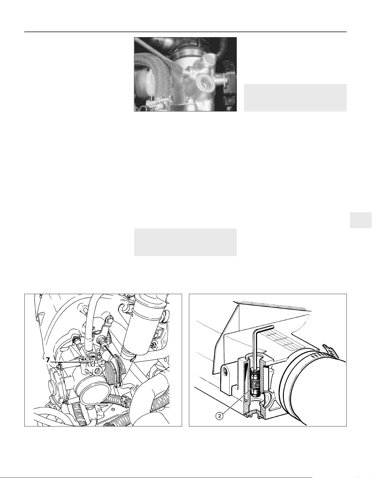
Peugeot dealer, for diagnosis. On all singlepoint fuel injection models, the idle speed and
mixture CO content is controlled by the
engine management ECU and cannot be
adjusted. If the idle speed and/or CO level is
incorrect, there is likely to be a fault in the
engine management system (see Chapter 4B).
Multi-point fuel injection models
Idle speed adjustment
21 Ensure that all electrical loads are
switched off. If the car does not have a
tachometer (rev counter), connect one to the
engine, following its manufacturer’s
instructions. Note the idle speed, and
compare it with that specified.
22 If adjustment is necessary, turn the air
screw (LE2-Jetronic) or idle speed adjustment
screw (LU2-Jetronic and Motronic M1.3) in
the throttle housing to obtain the specified
idling speed (see illustrations). If, on the LE2Jetronic system, the correct speed cannot be
obtained by means of the air screw, check
and adjust the throttle initial position as
described in Chapter 4C, Section 10.
Idle mixture CO level adjustment
Note: Adjustment of the idle mixture CO
content is only possible on the LE2-Jetronic
system. On The LU2-Jetronic and Motronic
M1.3 systems it is controlled by the fuel
injection system ECU.
23 The idle mixture (exhaust gas CO level) is
set at the factory, and should require no
further adjustment. If, due to a change in
engine characteristics (carbon build-up, bore
wear etc) or after a major overhaul, the
mixture setting is lost, it can be reset. Note,
however, that an exhaust gas analyser (CO
meter) will be required to check the mixture, in
order to set it with the necessary standard of
accuracy; if this is not available, the car must
be taken to a Peugeot dealer for the work to
be carried out.
24 If an exhaust gas analyser is available,
follow its manufacturer’s instructions to check
the exhaust gas CO level. If adjustment is
required, prise out the tamperproof cap on the
airflow sensor and use an Allen key to adjust
the mixture (see illustration). Turn the screw
in to richen the mixture and out to weaken it.
25 Blip the throttle two or three times and
then recheck that the idle speed and mixture
is correct.
26 When adjustments are complete,
disconnect the test equipment, and fit a new
tamperproof plug to the mixture adjustment
screw.
29 Emissions control systems
check
1
1 Details of the emissions control system
components are given in Chapter 4D.
2 Checking consists simply of a visual check
for obvious signs of damaged or leaking
hoses and joints. On engines incorporating a
breather filter in the oil filler cap, this should
be removed and cleaned, or renewed if it is
particularly contaminated.
3 Detailed checking and testing of the
evaporative and/or exhaust emissions
systems (as applicable) should be entrusted
to a Peugeot dealer.
30 Road test
1
Instruments and electrical
equipment
1 Check the operation of all instruments and
electrical equipment.
2 Make sure that all instruments read
correctly, and switch on all electrical
equipment in turn to check that it functions
properly.
Steering and suspension
3 Check for any abnormalities in the steering,
suspension, handling or road “feel”.
4 Drive the vehicle, and check that there are
no unusual vibrations or noises.
5 Check that the steering feels positive, with
no excessive “sloppiness”, or roughness, and
check for any suspension noises when
cornering, or when driving over bumps.
Drivetrain
6 Check the performance of the engine,
clutch, transmission and driveshafts.
7 Listen for any unusual noises from the
engine, clutch and transmission.
8 Make sure that the engine runs smoothly
when idling, and that there is no hesitation
when accelerating.
Every 24 000 miles or 2 years 1•19
1
28.22a Idle speed air screw adjustment on
the LE2-Jetronic fuel injection system
28.22b Idle speed adjustment screw (7) on the LU2-Jetronic and
Motronic M1.3 fuel injection systems
28.24 Mixture adjustment screw (2)
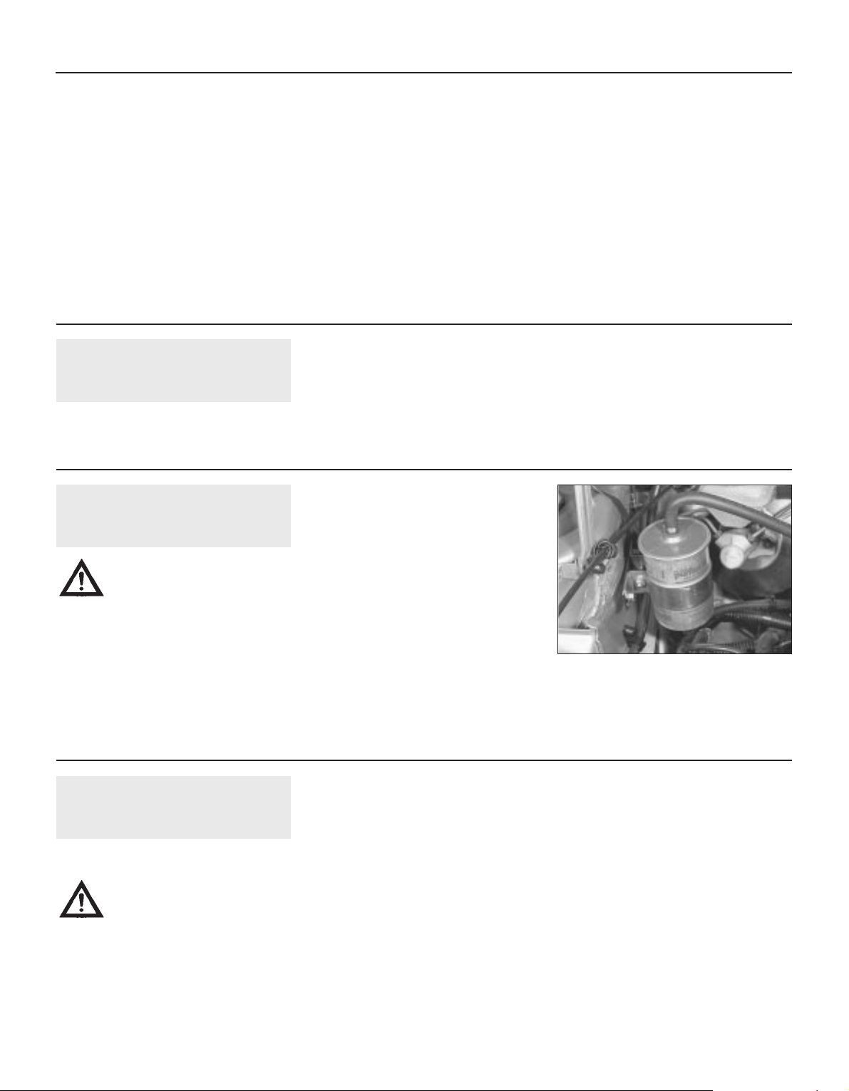
9 Check that the clutch action is smooth and
progressive, that the drive is taken up
smoothly, and that the pedal travel is not
excessive. Also listen for any noises when the
clutch pedal is depressed.
10 Check that all gears can be engaged
smoothly, without noise, and that the gear
lever action is not abnormally vague or
“notchy”.
11 Listen for a metallic clicking sound from
the front of the vehicle, as the vehicle is driven
slowly in a circle with the steering on full lock.
Carry out this check in both directions. If a
clicking noise is heard, this indicates wear in a
driveshaft joint, in which case, the complete
driveshaft must be renewed (see Chapter 8).
Check the operation and
performance of the braking
system
12 Make sure that the vehicle does not pull to
one side when braking, and that the wheels
do not lock prematurely when braking hard.
13 Check that there is no vibration through
the steering when braking.
14 Check that the handbrake operates
correctly, without excessive movement of the
lever, and that it holds the vehicle stationary
on a slope.
15 Test the operation of the brake servo unit
as follows. With the engine off, depress the
footbrake four or five times to exhaust the
vacuum. Start the engine, holding the brake
pedal depressed. As the engine starts, there
should be a noticeable “give” in the brake
pedal as vacuum builds up. Allow the engine
to run for at least two minutes, and then
switch it off. If the brake pedal is depressed
now, it should be possible to detect a hiss
from the servo as the pedal is depressed.
After about four or five applications, no further
hissing should be heard, and the pedal should
feel considerably firmer.
31 Timing belt renewal
3
Refer to Chapter 2B or 2C.
1•20 Every 24 000 miles or 2 years
Every 36 000 miles or 3 years
32 Fuel filter renewal - fuel
injection models
2
Warning: Before carrying out the
following operation, refer to the
precautions given in “Safety
first!” at the beginning of this
manual, and follow them implicitly. Petrol
is a highly-dangerous and volatile liquid,
and the precautions necessary when
handling it cannot be overstressed.
1 The fuel filter is situated on the engine
compartment bulkhead. Before disconnecting
any of the hoses from the filter it will be
necessary to depressurise the fuel system
(see Chapter 4B or 4C).
2 To renew the fuel filter first disconnect the
fuel hose, or unscrew the union bolt from the
top of the unit then place the bolt, union and
washers to one side and cover to prevent
ingress of dirt (see illustration). Unscrew the
clamp bolt, then lift the filter and unscrew the
bottom union. Dispose safely of the old filter;
it will be highly inflammable, and may explode
if thrown on a fire.
3 Fit the new filter using a reversal of the
removal procedure; making sure that dust and
dirt is prevented from entering the fuel lines.
Start the engine and check the filter hose
union connections for leaks.
33 Coolant renewal
2
Cooling system draining
Warning: Wait until the engine is
cold before starting this
procedure. Do not allow
antifreeze to come in contact
with your skin, or with the painted surfaces
of the vehicle. Rinse off spills immediately
with plenty of water. Never leave antifreeze
lying around in an open container, or in a
puddle in the driveway or on the garage
floor. Children and pets are attracted by its
sweet smell, but antifreeze can be fatal if
ingested.
1 With the engine completely cold, remove
the expansion tank filler cap. Turn the cap
anti-clockwise until it reaches the first stop.
Wait until any pressure remaining in the
system is released, then push the cap down,
turn it anti-clockwise to the second stop, and
lift it off.
2 Where fitted, unscrew the radiator filler cap
from the top left-hand side of the radiator.
3 Position a suitable container beneath the
coolant drain outlet at the lower left-hand side
of the radiator.
4 Unscrew the drain plug and allow the
coolant to drain into the container.
5 To assist draining, open the cooling system
bleed screws. These are located in the heater
matrix outlet hose union (to improve access, it
may be located in an extension hose) on the
engine compartment bulkhead, in the inlet
manifold coolant hose (XV, XW and XU series
engines) and on the top of the thermostat
housing (TU series engines) (see
illustrations).
6 When the flow of coolant stops, reposition
the container below the cylinder block drain
plug. On all engines except TU series, the
drain plug is located above the right-hand
driveshaft, or driveshaft intermediate bearing.
On TU series engines, the drain plug is
located at the front left-hand side of the
cylinder block.
Every 48 000 miles or 4 years
32.2 Fuel filter fuel hose and retaining
clamp locations
Every 2 years (regardless of mileage)
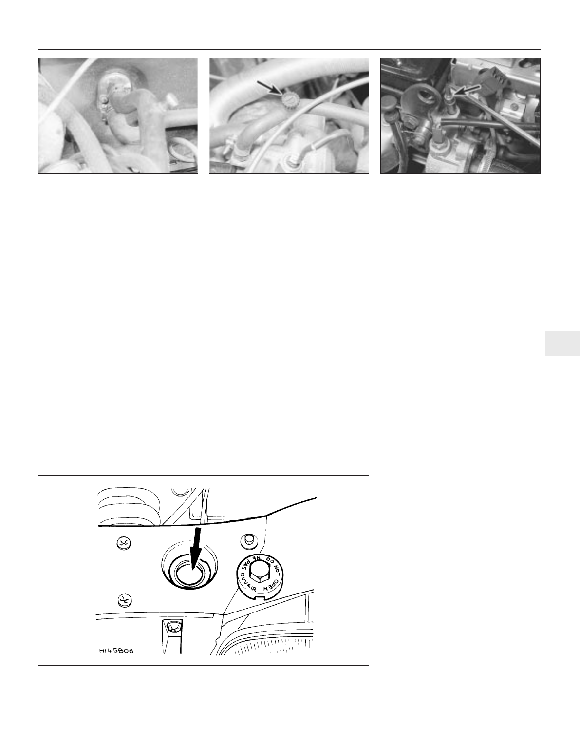
7 Remove the drain plug, and allow the
coolant to drain into the container.
8 If the coolant has been drained for a reason
other than renewal, then provided it is clean
and less than two years old, it can be re-used,
though this is not recommended.
9 Refit the radiator and cylinder block drain
plugs on completion of draining.
Cooling system flushing
10 If coolant renewal has been neglected, or
if the antifreeze mixture has become diluted,
then in time, the cooling system may gradually
lose efficiency, as the coolant passages
become restricted due to rust, scale deposits,
and other sediment. The cooling system
efficiency can be restored by flushing the
system clean.
11 The radiator should be flushed
independently of the engine, to avoid
unnecessary contamination.
Radiator flushing
12 To flush the radiator, first tighten the
radiator drain plug.
13 Disconnect the top and bottom hoses and
any other relevant hoses from the radiator,
with reference to Chapter 3.
14 Insert a garden hose into the radiator top
inlet. Direct a flow of clean water through the
radiator, and continue flushing until clean
water emerges from the radiator bottom
outlet.
15 If after a reasonable period, the water still
does not run clear, the radiator can be flushed
with a good proprietary cleaning agent. It is
important that their manufacturer’s
instructions are followed carefully. If the
contamination is particularly bad, insert the
hose in the radiator bottom outlet, and
reverse-flush the radiator.
Engine flushing
16 To flush the engine, first refit the cylinder
block drain plug, and tighten the cooling
system bleed screws.
17 Remove the thermostat as described in
Chapter 3, then temporarily refit the
thermostat cover.
18 With the top and bottom hoses
disconnected from the radiator, insert a
garden hose into the radiator top hose. Direct
a clean flow of water through the engine, and
continue flushing until clean water emerges
from the radiator bottom hose.
19 On completion of flushing, refit the
thermostat and reconnect the hoses with
reference to Chapter 3.
Cooling system filling
20 Before attempting to fill the cooling
system, make sure that all hoses and clips are
in good condition, and that the clips are tight.
Note that an antifreeze mixture must be used
all year round, to prevent corrosion of the
engine components (see following subSection). Also check that the radiator and
cylinder block drain plugs are in place and
tight.
21 Remove the expansion tank filler cap.
22 Open all the cooling system bleed screws
(see paragraph 4).
23 Some of the cooling system hoses are
positioned at a higher level than the top of the
radiator expansion tank. It is therefore
necessary to use a “header tank” when
refilling the cooling system, to reduce the
possibility of air being trapped in the system.
Although Peugeot dealers use a special
header tank, the same effect can be achieved
by using a suitable bottle, with a seal between
the bottle and the expansion tank. On some
engines, the expansion bottle/tank can be
simply released from its normal location,
raised as high as possible and tied to the
bonnet to form the “header” tank.
24 Fit the “header tank” to the expansion
tank and slowly fill the system. Where the
radiator incorporates a filler cap, fill the
radiator first until it is overflowing, and refit the
filler cap (see illustration). Now, on all
models, slowly fill the “header” tank. Coolant
will emerge from each of the bleed screws in
turn, starting with the lowest screw. As soon
as coolant free from air bubbles emerges from
the lowest screw, tighten that screw, and
watch the next bleed screw in the system.
Repeat the procedure until the coolant is
emerging from the highest bleed screw in the
cooling system and all bleed screws are
securely tightened.
25 If a separate bottle is being used as the
“header tank”, ensure it is full (at least 0.5
litres of coolant). If the vehicle expansion
bottle/tank is being used as the “header” tank,
ensure it is filled to the “MAX” markings (see
illustration). Start the engine, and run it at a
fast idle speed (do not exceed 2000 rpm) until
the cooling fan cuts in, and then cuts out.
During this time, squeeze the top and bottom
radiator hoses to allow any trapped air to rise.
Every 2 years 1•21
1
33.5a Cooling system bleed screws may
be located in the heater hose . . .
33.5b . . . in the inlet manifold coolant
hose . . .
33.5c . . . or on the thermostat housing
(arrowed)
33.24 Fill the radiator through the filler (arrowed) on the left-hand side
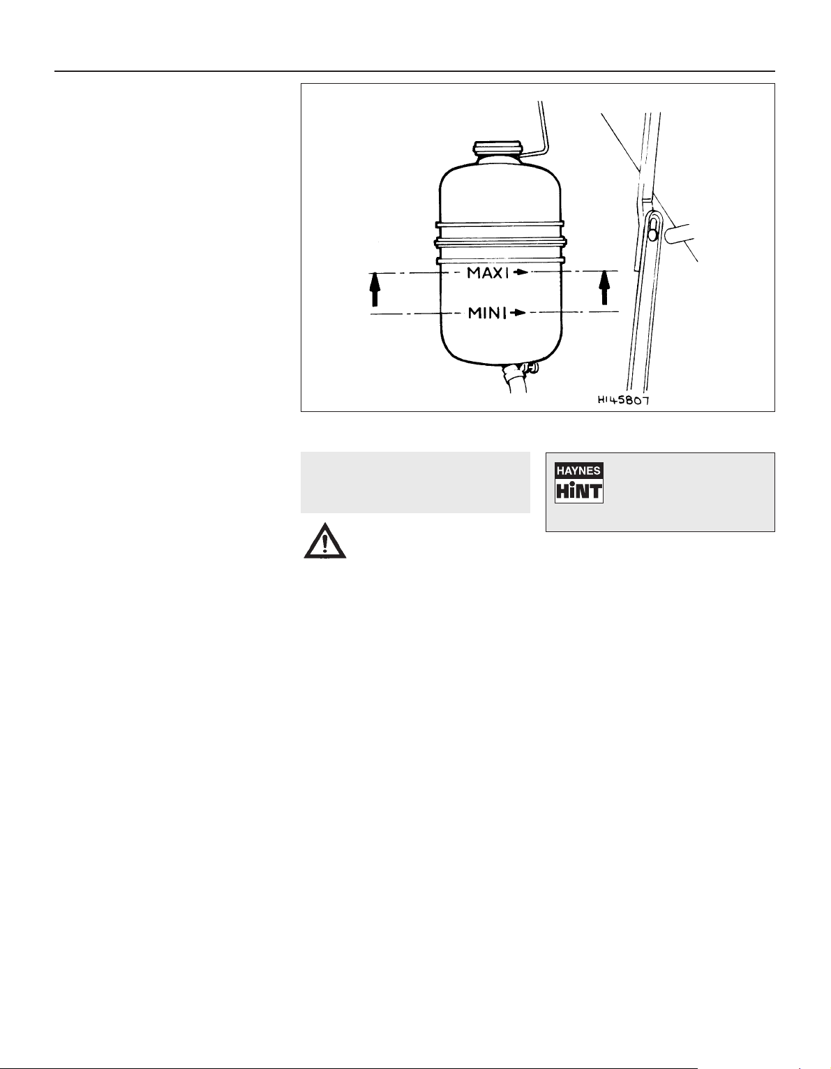
Slacken and retighten the bleed screws to
allow any air that has risen to escape. Note:
Take great care not to scald yourself with the
hot coolant during this operation.
26 Stop the engine and allow it engine to
cool, then remove the “header tank” or refit
the expansion bottle/tank to its original
location.
27 When the engine has cooled, check the
coolant level with reference to Section 3 of
this Chapter. Top-up the level if necessary,
and refit the expansion tank cap.
Note: If, after draining and refilling the system,
symptoms of overheating are found which did
not occur previously, then the fault is almost
certainly due to trapped air at some point in
the system, causing an air-lock and restricting
the flow of coolant; usually, the air is trapped
because the system was refilled too quickly. In
some cases, air-locks can be released by
tapping or squeezing the various hoses. If the
problem persists, stop the engine and allow it
to cool down completely, before unscrewing
the expansion tank filler cap, slackening the
bleed screws, or disconnecting hoses to bleed
out the trapped air.
Antifreeze mixture
28 The antifreeze should always be renewed
at the specified intervals. This is necessary
not only to maintain the antifreeze properties,
but also to prevent corrosion which would
otherwise occur as the corrosion inhibitors
become progressively less effective.
29 Always use an ethylene-glycol based
antifreeze which is suitable for use in mixedmetal cooling systems. The quantity of
antifreeze and levels of protection are
indicated in the Specifications.
30 Before adding antifreeze, the cooling
system should be completely drained,
preferably flushed, and all hoses checked for
condition and security.
31 After filling with antifreeze, a label should
be attached to the expansion tank, stating the
type and concentration of antifreeze used,
and the date installed. Any subsequent
topping-up should be made with the same
type and concentration of antifreeze.
32 Do not use engine antifreeze in the
windscreen/tailgate washer system, as it will
cause damage to the vehicle paintwork. A
screenwash additive should be added to the
washer system in the quantities stated by the
makers.
34 Brake fluid renewal
2
Warning: Brake hydraulic fluid
can harm your eyes and damage
painted surfaces, so use
extreme caution when handling
and pouring it. Do not use fluid that has
been standing open for some time, as it
absorbs moisture from the air. Excess
moisture can cause a dangerous loss of
braking effectiveness.
1 The procedure is similar to that for the
bleeding of the hydraulic system as described
in Chapter 9, except that the brake fluid
reservoir should be emptied by siphoning,
using a clean poultry baster or similar before
starting, and allowance should be made for
the old fluid to be expelled when bleeding a
section of the circuit.
2 Working as described in Chapter 9, open
the first bleed screw in the sequence, and
pump the brake pedal gently until nearly all
the old fluid has been emptied from the
master cylinder reservoir.
3 Top-up to the “MAX” level with new fluid,
and continue pumping until only the new fluid
remains in the reservoir, and new fluid can be
seen emerging from the bleed screw. Tighten
the screw, and top the reservoir level up to the
“MAX” level line.
4 Work through all the remaining bleed
screws in the sequence until new fluid can be
seen at all of them. Be careful to keep the
master cylinder reservoir topped-up to above
the “MIN” level at all times, or air may enter
the system and greatly increase the length of
the task.
5 When the operation is complete, check that
all bleed screws are securely tightened, and
that their dust caps are refitted. Wash off all
traces of spilt fluid, and recheck the master
cylinder reservoir fluid level.
6 Check the operation of the brakes before
taking the car on the road.
1•22 Every 2 years
33.25 Where possible, lift out the expansion bottle, suspend it from the bonnet to form a
“header” tank and fill to the “MAX” mark
Old hydraulic fluid is
invariably much darker in
colour than the new, making
it easy to distinguish the two.

2A
Chapter 2 Part A:
XV, XW and XY engines in-car repair procedures
Engine general
Code and displacement:
XV8 (108C) . . . . . . . . . . . . . . . . . . . . . . . . . . . . . . . . . . . . . . . . . . . . . 954 cc
XW7 (109F) . . . . . . . . . . . . . . . . . . . . . . . . . . . . . . . . . . . . . . . . . . . . . 1124 cc
XY7 (150D) . . . . . . . . . . . . . . . . . . . . . . . . . . . . . . . . . . . . . . . . . . . . . 1360 cc
XY8 (150B) . . . . . . . . . . . . . . . . . . . . . . . . . . . . . . . . . . . . . . . . . . . . . 1360 cc
Bore:
XV8 . . . . . . . . . . . . . . . . . . . . . . . . . . . . . . . . . . . . . . . . . . . . . . . . . . . 70.0 mm
XW7 . . . . . . . . . . . . . . . . . . . . . . . . . . . . . . . . . . . . . . . . . . . . . . . . . . . 72.0 mm
XY7 and XY8 . . . . . . . . . . . . . . . . . . . . . . . . . . . . . . . . . . . . . . . . . . . . 75.0 mm
Stroke:
XV8 . . . . . . . . . . . . . . . . . . . . . . . . . . . . . . . . . . . . . . . . . . . . . . . . . . . 62.0 mm
XW7 . . . . . . . . . . . . . . . . . . . . . . . . . . . . . . . . . . . . . . . . . . . . . . . . . . . 69.0 mm
XY7 and XY8 . . . . . . . . . . . . . . . . . . . . . . . . . . . . . . . . . . . . . . . . . . . . 77.0 mm
Compression ratio:
XV8 . . . . . . . . . . . . . . . . . . . . . . . . . . . . . . . . . . . . . . . . . . . . . . . . . . . 9.3 : 1
XW7 . . . . . . . . . . . . . . . . . . . . . . . . . . . . . . . . . . . . . . . . . . . . . . . . . . . 9.7 : 1
XY7 and XY8 . . . . . . . . . . . . . . . . . . . . . . . . . . . . . . . . . . . . . . . . . . . . 9.7: 1
Direction of crankshaft rotation . . . . . . . . . . . . . . . . . . . . . . . . . . . . . . . Clockwise (viewed from right-hand side of vehicle)
Firing order . . . . . . . . . . . . . . . . . . . . . . . . . . . . . . . . . . . . . . . . . . . . . . . 1-3-4-2 (No 1 cylinder at flywheel end of engine)
Valve clearances (engine cold)
Pre-January 1987 models:
Inlet . . . . . . . . . . . . . . . . . . . . . . . . . . . . . . . . . . . . . . . . . . . . . . . . . . . 0.10 mm
Exhaust . . . . . . . . . . . . . . . . . . . . . . . . . . . . . . . . . . . . . . . . . . . . . . . . 0.25 mm
January 1987 on, from the following engine numbers:
XV8 . . . . . . . . . . . . . . . . . . . . . . . . . . . . . . . . . . . . . . . . . . . . . . . . . . . 28401
XW7 . . . . . . . . . . . . . . . . . . . . . . . . . . . . . . . . . . . . . . . . . . . . . . . . . . . 42460
XY7 . . . . . . . . . . . . . . . . . . . . . . . . . . . . . . . . . . . . . . . . . . . . . . . . . . . 877201
XY8 . . . . . . . . . . . . . . . . . . . . . . . . . . . . . . . . . . . . . . . . . . . . . . . . . . . 877001
Inlet . . . . . . . . . . . . . . . . . . . . . . . . . . . . . . . . . . . . . . . . . . . . . . . . . 0.15 mm
Exhaust . . . . . . . . . . . . . . . . . . . . . . . . . . . . . . . . . . . . . . . . . . . . . . 0.30 mm
Oil pump
Endfloat . . . . . . . . . . . . . . . . . . . . . . . . . . . . . . . . . . . . . . . . . . . . . . . . . . 0.02 to 0.10 mm
Maximum lobe-to-body clearance . . . . . . . . . . . . . . . . . . . . . . . . . . . . . 0.064 mm
Auxiliary drivebelt check and renewal . . . . . . . . . . . . . . .See Chapter 1
Camshaft and rocker arms - removal, inspection and refitting . . . . . 6
Compression test - description and interpretation . . . . . . . . . . . . . . 3
Crankshaft oil seals - renewal . . . . . . . . . . . . . . . . . . . . . . . . . . . . . . 8
Cylinder head - removal and refitting . . . . . . . . . . . . . . . . . . . . . . . . 7
Engine/transmission mountings - inspection and renewal . . . . . . . . 10
Engine oil and filter renewal . . . . . . . . . . . . . . . . . . . . . . .See Chapter 1
Engine oil level check . . . . . . . . . . . . . . . . . . . . . .See “
Weekly checks”
Flywheel - removal, inspection and refitting . . . . . . . . . . . . . . . . . . . 9
General information . . . . . . . . . . . . . . . . . . . . . . . . . . . . . . . . . . . . . . 1
Oil pump - removal, inspection and refitting . . . . . . . . . . . . . . . . . . . 5
Timing chain, tensioner and sprockets - removal and refitting . . . . . 4
Valve clearances - checking and adjustment . . . . . . . . . . . . . . . . . . 2
2A•1
Specifications
Contents
Easy, suitable for
novice with little
experience
Fairly easy, suitable
for beginner with
some experience
Fairly difficult,
suitable for competent
DIY mechanic
Difficult, suitable for
experienced DIY
mechanic
Very difficult,
suitable for expert DIY
or professional
Degrees of difficulty
5
4
3
2
1

Torque wrench settings Nm lbf ft
Engine mounting nuts . . . . . . . . . . . . . . . . . . . . . . . . . . . . . . . . . . . . . . . 34 25
Oil pump screws . . . . . . . . . . . . . . . . . . . . . . . . . . . . . . . . . . . . . . . . . . . 7 5
Cylinder head bolts:
Stage 1 . . . . . . . . . . . . . . . . . . . . . . . . . . . . . . . . . . . . . . . . . . . . . . . . 50 37
Stage 2 . . . . . . . . . . . . . . . . . . . . . . . . . . . . . . . . . . . . . . . . . . . . . . . . 77 57
Chain tensioner bolts . . . . . . . . . . . . . . . . . . . . . . . . . . . . . . . . . . . . . . . 7 5
Camshaft sprocket bolt . . . . . . . . . . . . . . . . . . . . . . . . . . . . . . . . . . . . . 73 54
Timing chain cover bolts . . . . . . . . . . . . . . . . . . . . . . . . . . . . . . . . . . . . . 7 5
Crankshaft pulley nut . . . . . . . . . . . . . . . . . . . . . . . . . . . . . . . . . . . . . . . 88 65
Flywheel bolts . . . . . . . . . . . . . . . . . . . . . . . . . . . . . . . . . . . . . . . . . . . . . 66 49
Rocker cover bolts . . . . . . . . . . . . . . . . . . . . . . . . . . . . . . . . . . . . . . . . . 7 5
1 General information
How to use this Chapter
This Part of Chapter 2 describes those
repair procedures that can reasonably be
carried out on the XV, XW and XY series
engines while they remain in the car. If the
engine has been removed from the car and is
being dismantled as described in Part D, any
preliminary dismantling procedures can be
ignored. Refer to Part B and C for information
on the XU series and TU series engines.
Part D describes the removal of the
engine/transmission from the vehicle, and the
full overhaul procedures that can then be
carried out.
Engine description
One of three different capacity engines in
this series may be fitted, the difference in
displacement being achieved by increasing
the bore and stroke. The engine, which has
four cylinders and an overhead camshaft, is
mounted transversely, driving the front
wheels, and it is inclined to the rear at an
angle of 72° from vertical.
The manual transmission is also mounted
transversely in line with and below the engine,
and the final drive to the roadwheels is via the
differential unit which is integral with the
transmission. Drive from the engine to the
transmission is by means of transfer gears
which are separately encased in the clutch
housing.
The crankcase, cylinder head, gearcase
and clutch housing are all manufactured from
aluminium alloy. Removable wet cylinder
liners are fitted; the aluminium pistons each
have two compression rings and one oil
control ring. The valves are operated by the
single overhead camshaft via rocker arms.
The camshaft drives the distributor at the
flywheel end. The timing sprocket, located at
the other end of the camshaft, incorporates a
separate eccentric lobe which actuates the
fuel pump. The timing chain is driven from the
crankshaft sprocket. Next to the timing chain
sprocket is the gearwheel which drives the oil
pump. This is mounted low down against the
crankcase face and is enclosed in the timing
chain cover.
The crankshaft runs in five shell type main
bearings and the endfloat is adjustable via a
pair of semi-circular thrustwashers.
Somewhat inconveniently, the lower half
crankcase interconnects the engine with the
transmission and limits the number of
operations that can be carried out with the
engine in the car. The engine and
transmissions share the same mountings. A
forced feed lubrication system is employed.
The oil pump is attached to the crankcase in
the lower section of the timing chest and it
incorporates the pressure relief valve. The
pump is driven by gears from the crankshaft.
Oil from the pump passes via an oilway to
the oil filter, and thence to the crankshaft main
bearings, connecting rod bearings and
transmission components. Another oilway
from the filter delivers oil to the overhead
camshaft and rocker components. Oil from
the cylinder head passes to the transfer gear
housing and then back to the sump contained
within the transmission housing.
Apart from the standard replaceable
canister filter located on the outside of the
crankcase there is a gauze filter incorporated
in the oil pump suction inlet within the
transmission casing.
Repair operations possible with
the engine in the car
The following work can be carried out with
the engine in the car:
a) Valve clearances - adjustment.
b) Compression pressure - testing.
c) Timing chain - removal and refitting.
d) Oil pump - removal, inspection and
refitting.
e) Camshaft and rocker arms - removal,
inspection and refitting.
f) Cylinder head - removal and refitting.
g) Cylinder head and pistons -
decarbonising.
h) Crankshaft oil seals - renewal.
i) Flywheel - removal and refitting.
j) Engine mountings - inspection and
renewal.
2 Valve clearances - checking
and adjustment
2
Note: The valve clearances must be checked
and adjusted only when the engine is cold.
1 The importance of having the valve
clearances correctly adjusted cannot be
overstressed, as they vitally affect the
performance of the engine. If the clearances
are too big, the engine will be noisy
(characteristic rattling or tapping noises) and
engine efficiency will be reduced, as the
valves open too late and close too early. A
more serious problem arises if the clearances
are too small, however. If this is the case, the
valves may not close fully when the engine is
hot, resulting in serious damage to the engine
(eg. burnt valve seats and/or cylinder head
warping/cracking). The clearances are
checked and adjusted as follows.
2 Disconnect the spark plug HT leads and
remove the oil filler/crankcase ventilation cap
from the rocker cover.
3 Remove the rocker cover and then turn the
engine using a spanner on the crankshaft
pulley nut until the valves on No 1 cylinder are
rocking (ie inlet valve opening and exhaust
valve closing).
4 The rocker arm clearances of both valves of
No 4 cylinder can now be checked and, if
necessary, adjusted. Remember that No 1
cylinder is at the flywheel/clutch end of the
engine.
5 The feeler blade of the correct thickness is
inserted between the valve stem and rocker
arm. When the clearance is correctly set the
feeler blade should be a smooth stiff sliding fit
between the valve stem and rocker arm. The
correct valve clearances are given in the
Specifications at the start of this Chapter. The
valve locations can be determined from the
position of the manifolds. Note that engines
manufactured from January 1987, with
2A•2 XV, XW and XY series engine in-car repair procedures
Turning the engine will be
easier if the spark plugs are
removed first - see Chapter 1.
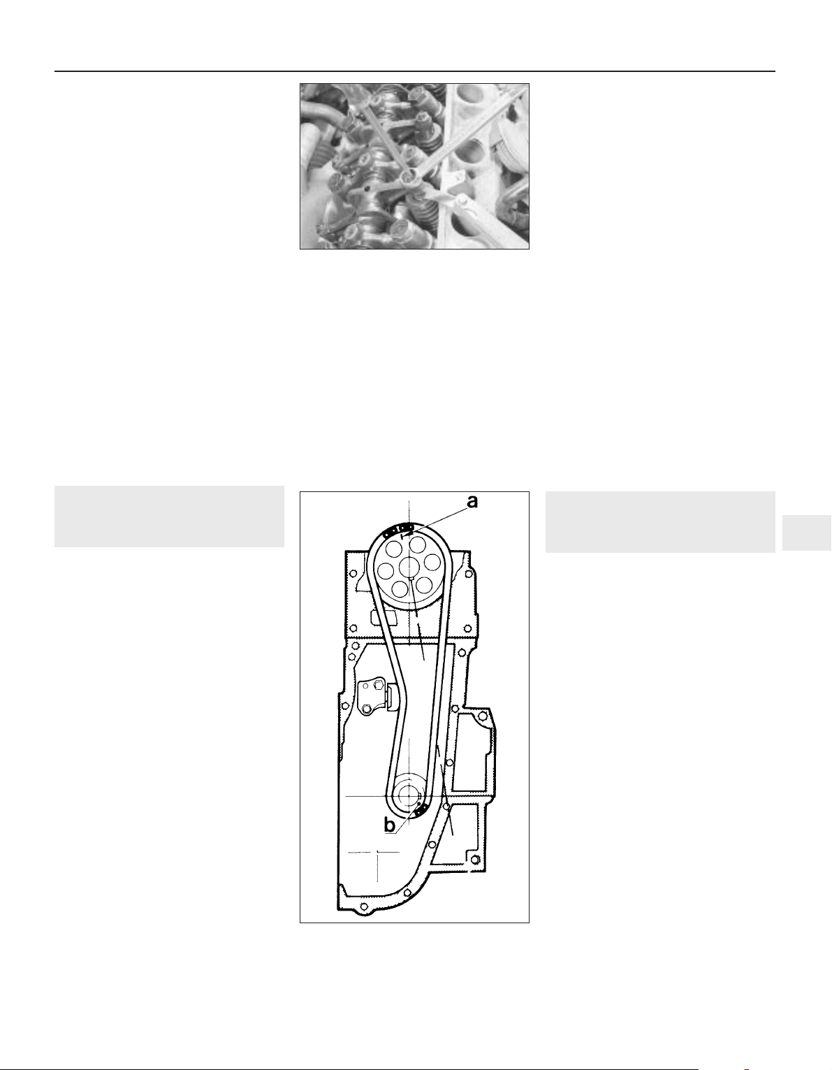
bi-metal rockers consisting of an aluminium
arm and steel pad, have different valve
clearances than earlier engines. Ensure that
the correct figures are used according to
engine type.
6 If the feeler blade is a tight or loose fit then
the clearance must be adjusted. To do this,
loosen the locknut of the adjustment stud and
screw the adjuster stud in or out until the
feeler blade can be felt to drag slightly when
drawn from the gap.
7 Hold the adjuster firmly in this position and
tighten the locknut. Recheck the gap on
completion to ensure that it has not altered
when locking the nut and stud (see
illustration).
8 Check each valve clearance in turn in the
following sequence remembering that the
clearances for inlet and exhaust valves are
different. The valves are numbered from the
flywheel end of the engine.
Valves rocking Valves to adjust
1 In 2 Ex 7 In 8 Ex
5 In 6 Ex 3 In 4 Ex
7 In 8 Ex 1 In 2 Ex
3 In 4 Ex 5 In 6 Ex
9 Fit the rocker cover using a new gasket,
then refit the spark plugs, HT leads and oil
filler/crankcase ventilation cap.
3 Compression test -
description and interpretation
1
1 When engine performance is down, or if
misfiring occurs which cannot be attributed to
the ignition or fuel systems, a compression
test can provide diagnostic clues as to the
engine’s condition. If the test is performed
regularly, it can give warning of trouble before
any other symptoms become apparent.
2 The engine must be fully warmed-up to
normal operating temperature, the battery
must be fully charged, and all the spark plugs
must be removed (Chapter 1). The aid of an
assistant will also be required.
3 Disable the ignition system by
disconnecting the ignition HT coil lead from
the distributor cap and earthing it on the
cylinder block. Use a jumper lead or similar
wire to make a good connection.
4 Fit a compression tester to the No 1
cylinder spark plug hole - the type of tester
which screws into the plug thread is to be
preferred.
5 Have the assistant hold the throttle wide
open, and crank the engine on the starter
motor; after one or two revolutions, the
compression pressure should build up to a
maximum figure, and then stabilise. Record
the highest reading obtained.
6 Repeat the test on the remaining cylinders,
recording the pressure in each.
7 All cylinders should produce very similar
pressures; a difference of more than 2 bars
between any two cylinders indicates a fault.
Note that the compression should build up
quickly in a healthy engine; low compression
on the first stroke, followed by graduallyincreasing pressure on successive strokes,
indicates worn piston rings. A low
compression reading on the first stroke, which
does not build up during successive strokes,
indicates leaking valves or a blown head
gasket (a cracked head could also be the
cause). Deposits on the undersides of the
valve heads can also cause low compression.
8 Although Peugeot do not specify exact
compression pressures, as a guide, any
cylinder pressure of below 10 bars can be
considered as less than healthy. Refer to a
Peugeot dealer or other specialist if in doubt
as to whether a particular pressure reading is
acceptable.
9 If the pressure in any cylinder is low, carry
out the following test to isolate the cause.
Introduce a teaspoonful of clean oil into that
cylinder through its spark plug hole, and
repeat the test.
10 If the addition of oil temporarily improves
the compression pressure, this indicates that
bore or piston wear is responsible for the
pressure loss. No improvement suggests that
leaking or burnt valves, or a blown head
gasket, may be to blame.
11 A low reading from two adjacent cylinders
is almost certainly due to the head gasket
having blown between them; the presence of
coolant in the engine oil will confirm this.
12 If one cylinder is about 20 percent lower
than the others and the engine has a slightly
rough idle, a worn camshaft lobe could be the
cause.
13 If the compression reading is unusually
high, the combustion chambers are probably
coated with carbon deposits. If this is the
case, the cylinder head should be removed
and decarbonised.
14 On completion of the test, refit the spark
plugs and reconnect the ignition system.
4 Timing chain, tensioner and
sprockets - removal and
refitting
3
Removal
1 Support the engine/transmission on a
trolley jack with a block of wood as an
insulator.
2 Release the nuts on the right-hand flexible
engine mounting at the base of the timing
chain cover.
3 Raise the engine just enough to clear the
side-member and anti-roll bar.
4 Remove the auxiliary drivebelt as described
in Chapter 1, and the fuel pump as described
in Chapter 4A.
5 Unscrew and remove the crankshaft pulley
nut. To do this the crankshaft must be held
against rotation by jamming the starter ring
gear. Remove the starter, as described in
Chapter 5A. Alternatively, if an assistant is
available, apply the brakes fully with a gear
engaged. Withdraw the pulley.
6 Unbolt and remove the rocker cover, and
disconnect the spark plug HT leads.
7 Unscrew and remove the timing chain
cover bolts. Take off the cover and extract the
fuel pump operating rod.
8 Turn the crankshaft either by temporarily
refitting the pulley nut or by engaging a gear
and turning a front wheel (raised) until the
timing marks are located in the following
positions. Camshaft sprocket mark between
two bright links on chain. Crankshaft sprocket
mark opposite centre of single bright link (see
illustration).
XV, XW and XY series engine in-car repair procedures 2A•3
2A
2.7 Adjusting the valve clearances
4.8 Sprocket timing marks and timing
chain bright links aligned
a Camshaft sprocket timing mark
b Crankshaft sprocket timing mark

9 Remove the crankshaft oil pump drivegear
and its Woodruff key.
10 Unbolt the oil pump. Some
socket-headed screws are accessible through
the holes in the driven gear (see illustration).
Lift off the pump and spacer plate (see
illustration).
11 Jam the camshaft sprocket and unscrew
the sprocket retaining bolt. Take off the fuel
pump operating eccentric.
12 Turn the lock on the chain tensioner
anti-clockwise to lock it in its retracted state
(see illustration).
13 Remove the camshaft sprocket with
timing chain.
14 Thoroughly clean all the removed
components ensuring that all traces of old
gasket are removed from the timing cover,
rocker cover and engine mating faces.
15 Examine the teeth of both sprockets for
wear. Each tooth on a sprocket is an inverted
V-shape and wear is apparent when one side
of the tooth becomes more concave in shape
than the other. When badly worn, the teeth
become hoop-shaped and the sprockets
must be renewed. The crankshaft sprocket
and oil pump drive gear are removed by
sliding them off the crankshaft with their
Woodruff keys.
16 If the sprockets need to be renewed then
the chain will have worn also and should also
be renewed. If the sprockets are satisfactory,
examine the chain and look for play between
the links. When the chain is held out
horizontally, it should not bend appreciably.
Remember, a chain is only as strong as its
weakest link and, being a relatively cheap
item, it is worthwhile fitting a replacement
anyway.
17 Check the condition of the tensioner
slipper. If it is worn, renew it; it is held in
position by two bolts. If the tensioner is
removed, note the fine mesh filter screen
located behind the tensioner body. Ensure
that it is clean and in place when refitting the
tensioner.
18 Inspect the oil pump drive gears for wear
or damage and renew if necessary. Always fit
a new timing cover oil seal (see Section 8).
Refitting
19 Check that the crankshaft is positioned
correctly by observing the crankshaft
sprocket keyway which should be in
alignment with the crankcase joint (see
illustration 4.8). Turn the crankshaft if
necessary to bring it to the correct position.
Temporarily fit the camshaft sprocket and
rotate the camshaft until the keyway is also
positioned as shown.
20 Engage the chain around the crankshaft
sprocket so that the timing mark on the
sprocket is in the centre of the single bright
link on the chain (see illustration).
21 Now engage the upper loop of the chain
over the camshaft sprocket so that the timing
mark is between the two bright links on the
chain (see illustration).
22 Now offer the camshaft sprocket to the
shaft. Adjust the position of the camshaft so
that the sprocket keyway aligns with the key.
23 Push the camshaft sprocket into position.
Insert and tighten its retaining bolt with the
fuel pump eccentric correctly located (see
illustration).
2A•4 XV, XW and XY series engine in-car repair procedures
4.12 Timing chain tensioner lock (2)
Turn in direction of arrow to release slipper -
turn in opposite direction to retract slipper
4.10b Removing the oil pump and spacer
plate
4.10a Removing oil pump screw with Allen
key
4.20 Timing chain bright link (arrowed) positioned over crankshaft
sprocket timing mark
4.21 Camshaft sprocket timing mark positioned between two
bright links (arrowed) on chain
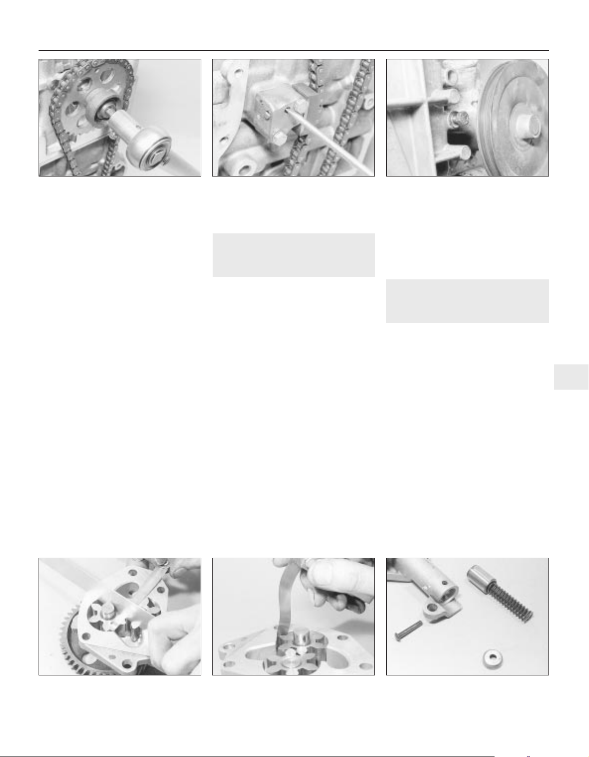
24 Using a very thin screwdriver blade, turn
the lock on the chain tensioner fully clockwise
to release the slipper (see illustration).
25 Check that the locating dowel is in
position and fit the oil pump with spacer plate.
If the pump driven sprocket is hard to turn,
release the pump mounting bolts and turn the
pump slightly on its locating dowel.
Re-tighten the bolts.
26 Fit the oil pump drivegear to the
crankshaft.
27 Bolt on the timing chain cover using a new
gasket. The bolt nearest the coolant pump
pulley must be located in the cover before
offering it up, otherwise the pulley will prevent
the bolt entering its cover hole (see
illustration). Do not tighten the cover bolts until
the crankshaft pulley has been pushed into
place to centralise the cover. Fit the coolant
hose safety rod under its cover bolts. This rod
prevents the coolant hose being cut by the rim
of the coolant pump pulley should the hose sag.
28 Fit the fuel pump operating rod and fuel
pump with reference to Chapter 4A, if
necessary.
29 Tighten the timing chain cover bolts to the
specified torque and then trim the upper ends
of the gasket flush. Fit the rocker cover using
a new gasket. Do not overtighten the securing
bolts.
30 Tighten the crankshaft pulley nut to the
specified torque, again jamming the flywheel
to prevent the crankshaft rotating.
31 Refit the starter, if removed (Chapter 5A).
32 Refit and tension the auxiliary drivebelt
(Chapter 1).
33 Lower the engine, reconnect the
mounting.
5 Oil pump - removal,
inspection and refitting
3
Removal
1 Carry out the operations described in
Section 4, paragraphs 1 to 10.
Inspection
2 The oil pump gears are exposed once the
spacer plate is removed.
3 Side movement of the gear spindles will
indicate wear in the bushes and the pump
should be renewed complete.
4 Worn or chipped gear teeth must be
rectified by renewal of the gear.
5 Check the endfloat of the gears using a
straight-edge and feeler blades (see
illustration).
6 Check the clearance between the tip of the
gear lobes and the oil pump body (see
illustration).
7 If any of these clearances exceed the
specified limit, renew the pump.
8 Remove the retaining pin from the relief
valve housing and withdraw the cup, spring,
guide and piston. Renew any worn
components (see illustration).
9 Check that the locating dowel is in position
and fit the oil pump with spacer plate. If the
pump driven sprocket is hard to turn, release
the pump mounting bolts and turn the pump
slightly on its locating dowel. Re-tighten the
bolts.
Refitting
10 Carry out the operations described in
Section 4, paragraphs 24 to 33.
6 Camshaft and rocker arms -
removal, inspection and
refitting
4
General information
1 The rocker arm assembly is secured to the
top of the cylinder head by the cylinder head
bolts. Although in theory it is possible to undo
the head bolts and remove the rocker arm
assembly without removing the head, in
practice, this is not recommended. Once the
bolts have been removed, the head gasket will
be disturbed, and the gasket will almost
certainly leak or blow after refitting. For this
reason, removal of the rocker arm assembly
cannot be done without removing the cylinder
head and renewing the head gasket.
2 The camshaft is slid out of the right-hand
end of the cylinder head, and it therefore
cannot be removed without first removing the
cylinder head, due to a lack of clearance.
Removal
Rocker arm assembly
3 Remove the cylinder head as described in
Section 7.
XV, XW and XY series engine in-car repair procedures 2A•5
2A
4.23 Tightening the camshaft sprocket
retaining bolt
4.24 Releasing the timing chain tensioner 4.27 Timing cover bolt next to coolant
pump pulley in place prior to fitting cover
5.5 Checking oil pump gear endfloat 5.6 Checking oil pump gear to body
clearance
5.8 Oil pump pressure relief valve
components
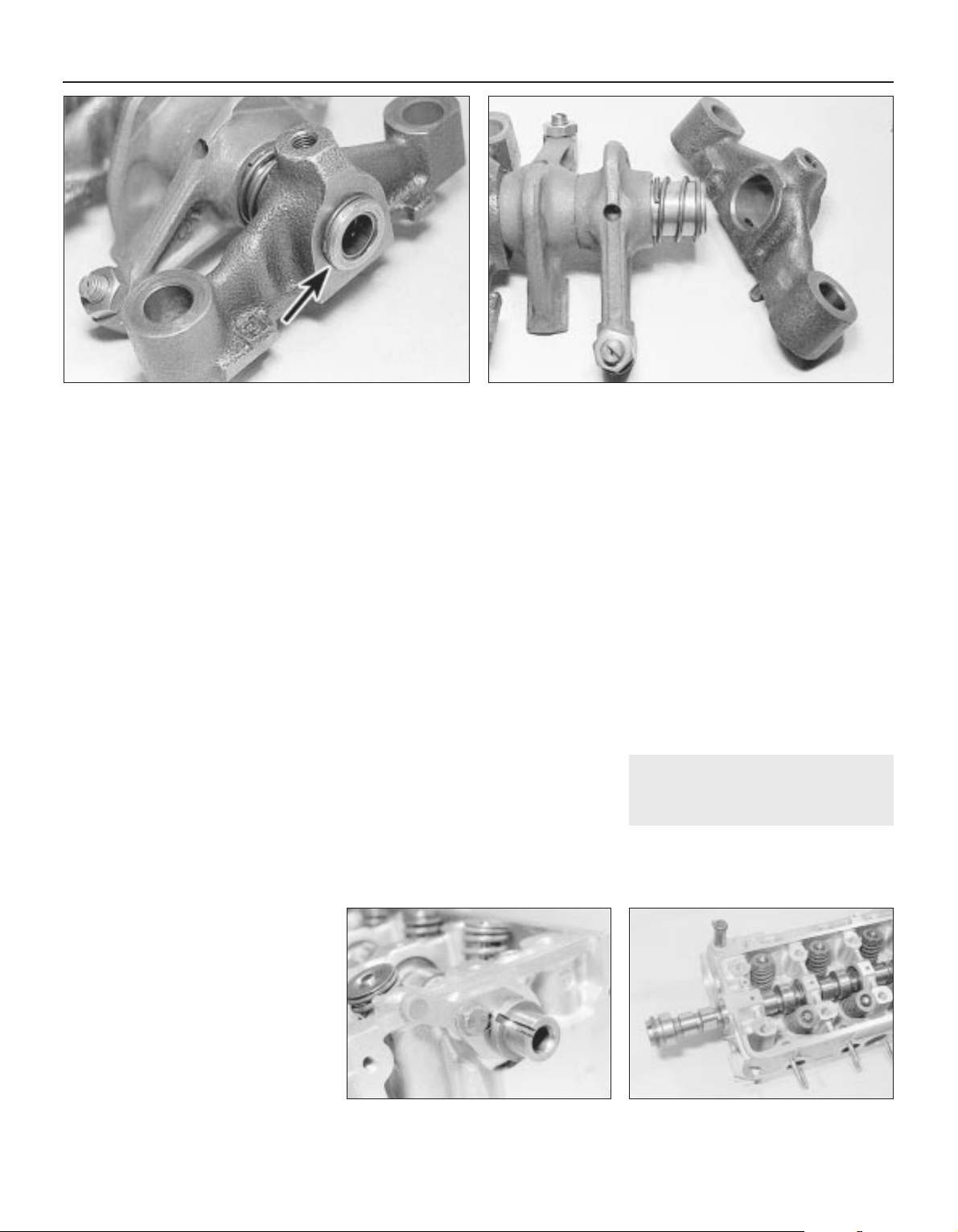
4 To dismantle the rocker arm assembly,
carefully prise off the circlip from the end of
the rocker shaft; retain the rocker pedestal, to
prevent it being sprung off the end of the
shaft. Slide the various components off the
end of the shaft, keeping all components in
their correct fitted order (see illustrations).
Make a note of each component’s correct
fitted position and orientation as it is removed,
to ensure it is fitted correctly on reassembly.
5 To separate the remaining pedestal and
shaft, first unscrew the rocker cover retaining
stud from the top of the pedestal; this can be
achieved using a stud extractor, or two nuts
locked together. With the stud removed,
unscrew the grub screw from the top of the
pedestal, and withdraw the rocker shaft.
Camshaft
6 Remove the cylinder head as described in
Section 7.
7 Undo the retaining bolt, and remove the
camshaft retaining thrust plate from the
cylinder head (see illustration).
8 Withdraw the camshaft taking care not to
scratch the bearing journals with the edges of
the cam lobes (see illustration).
Inspection
Rocker arm assembly
9 Examine the rocker arm bearing surfaces
which contact the camshaft lobes for wear
ridges and scoring. Renew any rocker arms
on which these conditions are apparent. If a
rocker arm bearing surface is badly scored,
also examine the corresponding lobe on the
camshaft for wear, as it is likely that both will
be worn. Renew worn components as
necessary. The rocker arm assembly can be
dismantled as described in paragraphs 4
and 5.
10 Inspect the ends of the (valve clearance)
adjusting screws for signs of wear or damage,
and renew as required.
11 If the rocker arm assembly has been
dismantled, examine the rocker arm and shaft
bearing surfaces for wear ridges and scoring.
If there are obvious signs of wear, the relevant
rocker arm(s) and/or the shaft must be
renewed.
Camshaft
12 Examine the camshaft bearing surfaces
and cam lobes for signs of wear ridges and
scoring. Renew the camshaft if any of these
conditions are apparent. Examine the
condition of the bearing surfaces, both on the
camshaft journals and in the cylinder head. If
the head bearing surfaces are worn
excessively, the cylinder head will need to be
renewed. If the necessary measuring
equipment is available, camshaft bearing
journal wear can be checked by direct
measurement, noting that No 1 journal is at
the transmission end of the head.
13 Examine the thrust plate for signs of wear
or scoring, and renew as necessary.
Refitting
Camshaft
14 Ensure that the cylinder head and
camshaft bearing surfaces are clean, then
liberally oil the camshaft bearings and lobes.
Slide the camshaft back into position in the
cylinder head.
15 Locate the thrust plate in position, refit the
plate retaining bolt, tightening it to the
specified torque setting.
Rocker arm assembly
16 If the rocker arm assembly was
dismantled, refit the rocker shaft to the
pedestal, aligning its locating hole with the
pedestal threaded hole. Refit the grub screw,
and tighten it securely. With the grub screw in
position, refit the rocker cover mounting stud
to the pedestal, and tighten it securely. Apply
a smear of clean engine oil to the shaft, then
slide on all removed components, ensuring
each is correctly fitted in its original position.
Once all components are in position on the
shaft, compress the remaining pedestal and
refit the circlip. Ensure that the circlip is
correctly located in its groove on the shaft.
17 Refit the cylinder head and rocker arm
assembly as described in Section 7.
7 Cylinder head - removal and
refitting
4
Note: If the crankshaft is to be rotated after
removal of the cylinder head (for cleaning the
pistons) it will be necessary to use the
Peugeot special tool to hold the camshaft
2A•6 XV, XW and XY series engine in-car repair procedures
6.7 Camshaft retaining thrust plate 6.8 Removing the camshaft
6.4a Prise off the circlip (arrowed) from the end of the
rocker shaft . . .
6.4b . . . and slide the components off the shaft
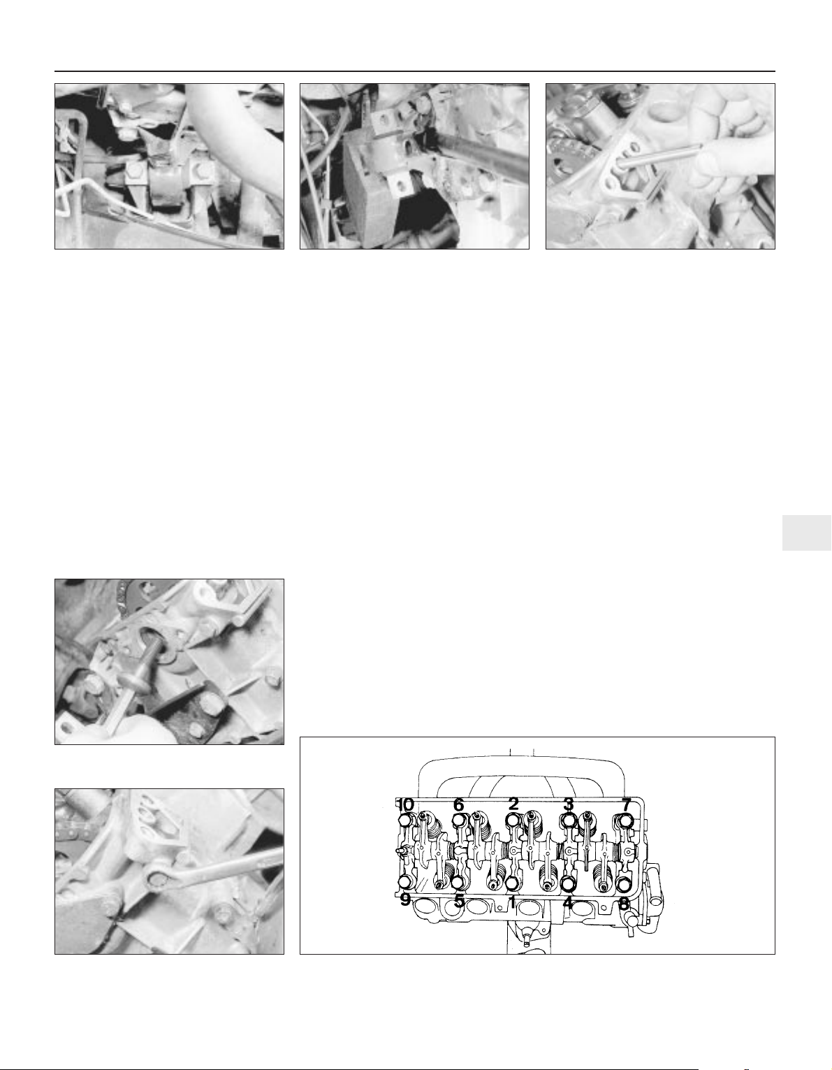
sprocket, or fabricate a suitable alternative. If it
will not be necessary to rotate the crankshaft,
the home-made tool described in the text will
suffice.
Removal
1 Disconnect and remove the battery, as
described in Chapter 5A.
2 Remove the air cleaner, complete with
mounting brackets, hot air hose and inlet
hose, with reference to Chapter 4A. Also
remove the inlet cowl.
3 Drain the cooling system, as described in
Chapter 1.
4 Remove the engine oil filler/crankcase
ventilation cap and disconnect the hoses from
the inlet cowl and carburettor.
5 Chock the rear wheels then jack up the
front of the car and support it on axle stands
(see “Jacking and vehicle support”).
6 Disconnect the gearchange selector and
engagement rods with reference to Chapter 7A.
Unscrew the engagement rod nut. Make sure
that the gears are in neutral.
7 Unscrew the bolt and nuts, and disconnect
the exhaust downpipe from the exhaust
manifold.
8 Loosen the left-hand engine mounting nuts
beneath the battery tray so that the mounting
is lowered by approximately 4.0 mm.
9 Disconnect the heater hoses from the
bulkhead, water pump and cylinder head
outlet.
10 Remove the fuel pump, as described in
Chapter 4A.
11 Disconnect the top hose from the
thermostat housing.
12 Disconnect the temperature sender
wiring.
13 Remove the distributor, as described in
Chapter 5B.
14 Disconnect the spark plug HT leads and
remove them from the rocker cover.
15 Disconnect the throttle and choke cables,
as described in Chapter 4A.
16 Disconnect the brake servo vacuum hose
from the inlet manifold (if applicable) and
place to one side.
17 Unscrew and remove the two bolts
securing the right-hand rear engine mounting
to the subframe (see illustration).
18 Using a suitable long bar inserted through
the right-hand rear engine mounting bracket,
lever up the rear of the engine as far as
possible, without damaging the radiator, and
support with a block of wood (see
illustration). If necessary, loosen the left-hand
engine mounting to gain extra height. Make
sure that the right-hand front mounting is not
damaged by excessive twisting.
19 Unbolt the rocker cover and remove the
gasket.
20 Turn the engine on the crankshaft pulley
nut until the key slot in the camshaft is facing
upwards, then remove the ignition timing
aperture cover and turn the engine as
necessary until the mark on the flywheel is
aligned with the TDC mark on the timing
plate (refer to Chapter 5B if necessary).
Pistons No 2 and 3 will be at TDC.
21 Extract the fuel pump plunger from the
timing cover (see illustration).
22 Unbolt the access plate from the top of
the timing cover.
23 Unscrew and remove the camshaft
sprocket retaining bolt from the end of the
camshaft using an Allen key (retain the
sprocket with a suitable bar) (see
illustration).
24 Loosen the four bolts securing the timing
cover to the cylinder head (see illustration).
25 Progressively unscrew the cylinder head
bolts in the order shown (see illustration),
and recover the nuts from their channels in
the crankcase.
XV, XW and XY series engine in-car repair procedures 2A•7
2A
7.17 Right-hand rear engine mounting
bolts
7.18 Lever up the engine and support it on
a wooden block
7.21 Removing the fuel pump plunger
7.23 Unscrew and remove the camshaft
sprocket bolt
7.24 Loosen the bolts securing the timing
cover to the cylinder head
7.25 Sequence for tightening or loosening the cylinder head bolts
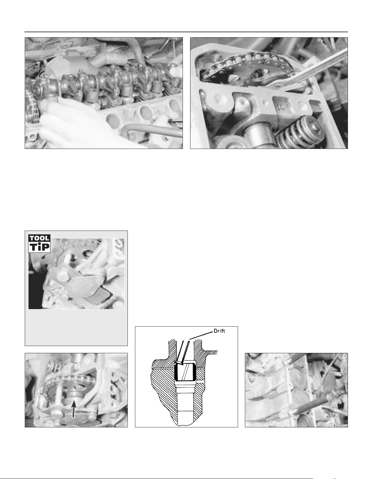
26 Remove the head bolts and lift off the
rocker shaft assembly (see illustration). It
may be necessary to leave one or two bolts in
the assembly if they foul the bulkhead due to
insufficient engine height.
27 Loosen the camshaft thrust plate bolt, pull
out the plate and temporarily retighten the
bolt (see illustration).
28 The camshaft sprocket must now be
supported in its normal position while the
cylinder head is removed. If it is allowed to
drop it will not be possible to lift it again
without releasing the timing chain tensioner
which will necessitate removal of the timing
cover. Peugeot dealers use a special mandrel,
tool number 70132, but as this is unlikely to
be available to the home mechanic it is
suggested that a plate and bolt are used,
together with the access plate (see Tool Tip).
29 Slide the camshaft from the fuel pump
eccentric and camshaft sprocket and let it
rest in the cylinder head (see illustration).
30 Before removing the cylinder head the
following must be noted. The cylinder head is
positioned during assembly by means of two
dowels. When removing the cylinder head it is
most important not to lift it directly from the
cylinder block; it must be twisted slightly. This
action prevents the cylinder liners from
sticking to the cylinder head face and being
lifted with it, thus breaking their bottom seals.
Before the cylinder head can be twisted, the
dowel at the flywheel end must be tapped
down flush with the top of the cylinder block,
using a drift (see illustration).
31 Remove the four timing cover-to-cylinder
head bolts then move the flywheel end of the
cylinder head sideways slightly to release the
gasket.
32 Lift the cylinder head from the block and
remove the gasket without disturbing the
liners. Do not turn the engine over as this also
will break the liner bottom seals. If further
work is to be carried out on the engine, such
as cleaning the tops of the cylinder liners, they
should be clamped in position using two
cylinder head bolts, metal tubing, and large
washers (see illustration).
Preparation for refitting
Note: As mentioned at the beginning of this
Section, the camshaft sprocket must be
supported in such a way that it will be allowed
to rotate as the crankshaft is turned to clean
the pistons. The Peugeot special tool locates
through the sprocket retaining bolt hole and is
bolted to the front of the timing cover. If this
tool cannot be obtained, a suitable alternative
can be easily fabricated.
33 With the camshaft sprocket supported so
as to allow rotation, commence the cleaning
operation as follows.
34 The mating faces of the cylinder head and
cylinder block/crankcase must be perfectly
clean before refitting the head. Use a hard
2A•8 XV, XW and XY series engine in-car repair procedures
7.29 Slide the camshaft from the fuel
pump eccentric (arrowed)
7.30 Driving the cylinder head dowel down
flush with the block face
7.26 Removing the rocker shaft assembly 7.27 Loosening the camshaft thrust plate bolt
In the absence of the Peugeot tool, a
nut and bolt used together with the
access plate can be used as shown to
prevent the camshaft sprocket from
dropping.
7.32 Using washers, tubing and the cylinder
head bolts to clamp the liners in position
 Loading...