

Peugeot 205 Diagramas Eléctricos
12
Chapter 12
Body electrical system
General
System type . . . . . . . . . . . . . . . . . . . . . . . . . . . . . . . . . . . . . . . . . . . . . . 12-volt negative earth
Fuses (early models)
No Circuit protected Rating (amp)
1 Reverse light, cooling fan relay, tachometer (GTI) . . . . . . . . . . . . . 10
2 Accessories, indicators, fuel gauge, warning lights, heater blower
motor . . . . . . . . . . . . . . . . . . . . . . . . . . . . . . . . . . . . . . . . . . . . . . . . 25
3 Ignition switch, wash/wipe system, stop-lights, tachometer (non-
GTI option), radio, heated rear window, electric window relay
(option), clock illumination (GTI). . . . . . . . . . . . . . . . . . . . . . . . . . . . 25
4 Central door locking (option) . . . . . . . . . . . . . . . . . . . . . . . . . . . . . . 10
5 Cooling fan . . . . . . . . . . . . . . . . . . . . . . . . . . . . . . . . . . . . . . . . . . . 25
6 Hazard warning switch . . . . . . . . . . . . . . . . . . . . . . . . . . . . . . . . . . 10
7 Spare . . . . . . . . . . . . . . . . . . . . . . . . . . . . . . . . . . . . . . . . . . . . . . . . -
8 Cigarette lighter, clock, interior lights, glovebox illumination, radio . . 20
9 Electric front windows . . . . . . . . . . . . . . . . . . . . . . . . . . . . . . . . . . . 25
10 Heated rear window, horns . . . . . . . . . . . . . . . . . . . . . . . . . . . . . . . 20
11 Rear foglight . . . . . . . . . . . . . . . . . . . . . . . . . . . . . . . . . . . . . . . . . . 5
12 Side/tail lights/warning light, instrument panel illumination, number
plate lights . . . . . . . . . . . . . . . . . . . . . . . . . . . . . . . . . . . . . . . . . . . . 5
13 (In-line) fuel pump (GTI) . . . . . . . . . . . . . . . . . . . . . . . . . . . . . . . . . . 25
Air compressor and horn (1.9 GTI models) - removal and refitting . . 21
Battery, bulbs and fuses . . . . . . . . . . . . . . . . . . . .See
“Weekly checks”
Bulbs (exterior lights) - renewal . . . . . . . . . . . . . . . . . . . . . . . . . . . . . 8
Bulbs (interior lights) - renewal . . . . . . . . . . . . . . . . . . . . . . . . . . . . . 9
Central door locking system - general information . . . . . . . . . . . . . . 19
Clock - removal and refitting . . . . . . . . . . . . . . . . . . . . . . . . . . . . . . . 6
Dim-dip lighting system - general information . . . . . . . . . . . . . . . . . 13
Electrical fault finding - general information . . . . . . . . . . . . . . . . . . . 2
Front direction indicator light unit - removal and refitting . . . . . . . . . 11
Fuses and relays - general information . . . . . . . . . . . . . . . . . . . . . . . 3
General information and precautions . . . . . . . . . . . . . . . . . . . . . . . . 1
Headlight beam alignment - checking and adjusting . . . . . . . . . . . . 12
Headlight unit - removal and refitting . . . . . . . . . . . . . . . . . . . . . . . . 10
Horn - removal and refitting . . . . . . . . . . . . . . . . . . . . . . . . . . . . . . . . 20
Instrument panel - removal and refitting . . . . . . . . . . . . . . . . . . . . . . 5
Radio - removal and refitting . . . . . . . . . . . . . . . . . . . . . . . . . . . . . . . 22
Speedometer cable - renewal . . . . . . . . . . . . . . . . . . . . . . . . . . . . . . 7
Screen washer fluid level check . . . . . . . . . . . . . .See
“Weekly checks”
Switches - removal and refitting . . . . . . . . . . . . . . . . . . . . . . . . . . . . 4
Tailgate heated window - general information . . . . . . . . . . . . . . . . . 18
Tailgate wiper motor - removal and refitting . . . . . . . . . . . . . . . . . . . 16
Vehicle immobiliser - general information . . . . . . . . . . . . . . . . . . . . . 23
Washer system - general information . . . . . . . . . . . . . . . . . . . . . . . . 17
Windscreen wiper motor and linkage - removal and refitting . . . . . . 15
Wiper arms - removal and refitting . . . . . . . . . . . . . . . . . . . . . . . . . . 14
Wiper blade check . . . . . . . . . . . . . . . . . . . . . . . .See
“Weekly checks”
12•1
Specifications
Contents
Easy,
suitable for
novice with little
experience
Fairly easy,
suitable
for beginner with
some experience
Fairly difficult,
suitable for competent
DIY mechanic
Difficult,
suitable for
experienced DIY
mechanic
Very difficult,
suitable for expert DIY
or professional
Degrees of difficulty
5
4
3
2
1
[Books Manuals Wiring Diagrams]
Fuses (1986 to 1988 GTI and CTI models)
No Circuit protected Rating (amp)
1 Reversing lights, tachometer . . . . . . . . . . . . . . . . . . . . . . . . . . . . . 10
2 Direction indicators, heater blower motor, oil pressure gauge, oil
temperature gauge, heated seats, fuel gauge, coolant temperature
gauge, low battery charge warning, oil pressure warning, brake
system warning, coolant temperature warning, low coolant
level warning . . . . . . . . . . . . . . . . . . . . . . . . . . . . . . . . . . . . . . . . . . 25
3 Windscreen wiper/washer, stop-lights, headlight washer, radio,
accessories . . . . . . . . . . . . . . . . . . . . . . . . . . . . . . . . . . . . . . . . . . . 25
4 Spare . . . . . . . . . . . . . . . . . . . . . . . . . . . . . . . . . . . . . . . . . . . . . . . . -
5 Hazard warning . . . . . . . . . . . . . . . . . . . . . . . . . . . . . . . . . . . . . . . . 10
6 Spare . . . . . . . . . . . . . . . . . . . . . . . . . . . . . . . . . . . . . . . . . . . . . . . . -
7 Cigarette lighter, clock, interior lights, boot light, central door
locking, radio . . . . . . . . . . . . . . . . . . . . . . . . . . . . . . . . . . . . . . . . . . 25
8 Horns . . . . . . . . . . . . . . . . . . . . . . . . . . . . . . . . . . . . . . . . . . . . . . . . 25
9 Electrically-operated windows . . . . . . . . . . . . . . . . . . . . . . . . . . . . 20
10 Rear foglight . . . . . . . . . . . . . . . . . . . . . . . . . . . . . . . . . . . . . . . . . . 5
11 Tail light (RH), number plate light . . . . . . . . . . . . . . . . . . . . . . . . . . 5
12 Tail light (LH) . . . . . . . . . . . . . . . . . . . . . . . . . . . . . . . . . . . . . . . . . . 5
13 Instrument panel illumination, side lights . . . . . . . . . . . . . . . . . . . . 5
14 Fuel pump . . . . . . . . . . . . . . . . . . . . . . . . . . . . . . . . . . . . . . . . . . . . 15
Fuses (1988 to 1989 models, except GTI and CTI)
No Circuit protected Rating (amp)
1 Reversing lights . . . . . . . . . . . . . . . . . . . . . . . . . . . . . . . . . . . . . . . . 10
2 Direction indicators, heater blower motor, ignition warning light . . 25
3 Fuel gauge, stop-lights, front and rear wash/wipe, tachometer,
headlight wash, radio, storage tray light, warning lights (coolant
temperature, oil pressure, coolant level, handbrake, choke) . . . . . 25
4 Spare . . . . . . . . . . . . . . . . . . . . . . . . . . . . . . . . . . . . . . . . . . . . . . . . -
5 Hazard warning . . . . . . . . . . . . . . . . . . . . . . . . . . . . . . . . . . . . . . . . 10
6 Spare . . . . . . . . . . . . . . . . . . . . . . . . . . . . . . . . . . . . . . . . . . . . . . . . -
7 Cigarette lighter, clock, interior lights, boot light, central door
locking, radio . . . . . . . . . . . . . . . . . . . . . . . . . . . . . . . . . . . . . . . . . . 25
8 Horns, heated rear window . . . . . . . . . . . . . . . . . . . . . . . . . . . . . . . 25
9 Electrically-operated windows . . . . . . . . . . . . . . . . . . . . . . . . . . . . 20
10 Rear fog light . . . . . . . . . . . . . . . . . . . . . . . . . . . . . . . . . . . . . . . . . . 5
11 Tail lights, number plate light . . . . . . . . . . . . . . . . . . . . . . . . . . . . . 5
12 Spare . . . . . . . . . . . . . . . . . . . . . . . . . . . . . . . . . . . . . . . . . . . . . . . . -
13 Instrument panel illumination, side lights . . . . . . . . . . . . . . . . . . . . 5
14 Fuel pump . . . . . . . . . . . . . . . . . . . . . . . . . . . . . . . . . . . . . . . . . . . . 15
Fuses (1988 to 1989 GTI and CTI models)
No Circuit protected Rating (amp)
1 Reversing lights, tachometer . . . . . . . . . . . . . . . . . . . . . . . . . . . . . 10
2 Direction indicators, heater blower motor, oil pressure gauge, oil
temperature gauge, heated seats, fuel gauge, coolant temperature
gauge, low battery charge warning, oil pressure warning, brake
system warning, coolant temperature warning, low coolant level
warning . . . . . . . . . . . . . . . . . . . . . . . . . . . . . . . . . . . . . . . . . . . . . . 25
3 Front and rear wash/wipe, stop-lights, headlight washer, radio,
accessories, storage tray light, map reading light . . . . . . . . . . . . . 25
4 Spare . . . . . . . . . . . . . . . . . . . . . . . . . . . . . . . . . . . . . . . . . . . . . . . . -
5 Hazard warning . . . . . . . . . . . . . . . . . . . . . . . . . . . . . . . . . . . . . . . . 10
6 Spare . . . . . . . . . . . . . . . . . . . . . . . . . . . . . . . . . . . . . . . . . . . . . . . . -
7 Cigarette lighter, clock, interior lights, boot light, central door
locking, radio . . . . . . . . . . . . . . . . . . . . . . . . . . . . . . . . . . . . . . . . . . 20
8 Horns, heated rear window . . . . . . . . . . . . . . . . . . . . . . . . . . . . . . . 25
9 Electrically-operated windows . . . . . . . . . . . . . . . . . . . . . . . . . . . . 20
10 Rear foglight . . . . . . . . . . . . . . . . . . . . . . . . . . . . . . . . . . . . . . . . . . 5
11 Tail light, number plate light . . . . . . . . . . . . . . . . . . . . . . . . . . . . . . 5
12 Spare . . . . . . . . . . . . . . . . . . . . . . . . . . . . . . . . . . . . . . . . . . . . . . . . 5
13 Instrument panel illumination, side lights . . . . . . . . . . . . . . . . . . . . 5
14 Fuel pump . . . . . . . . . . . . . . . . . . . . . . . . . . . . . . . . . . . . . . . . . . . . 15
12•2 Body electrical system
[Books Manuals Wiring Diagrams]
Fuses (1989 to 1991 - all models)
No Circuit protected Rating (amp)
1 Reversing lights, tachometer, fuel gauge, warning lights (low
battery charge, coolant temperature, oil pressure, low coolant
level, brake system, choke). . . . . . . . . . . . . . . . . . . . . . . . . . . . . . . 10
2 Direction indicators, gauges (fuel, oil temperature, . . . . . .coolant
temperature, oil pressure), heater blower . . .motor, warning lights
(low battery charge, coolant temperature, oil pressure, low coolant
level, brake system, choke) . . . . . . . . . . . . . . . . . . . . . . . . . . . . . . . 25
3 Map reading light, stop-lights, windscreen and tailgate wash/wipe,
tachometer, radio, glovebox light, electric windows, heated rear
window . . . . . . . . . . . . . . . . . . . . . . . . . . . . . . . . . . . . . . . . . . . . . . 25
4 Driving lights . . . . . . . . . . . . . . . . . . . . . . . . . . . . . . . . . . . . . . . . . . 15
5 Hazard warning lights . . . . . . . . . . . . . . . . . . . . . . . . . . . . . . . . . . . 10
6 Spare . . . . . . . . . . . . . . . . . . . . . . . . . . . . . . . . . . . . . . . . . . . . . . . . -
7 Cigarette lighter, clock, interior lights, luggage compartment light,
central locking, radio, power feed to tow bar . . . . . . . . . . . . . . . . . 25
8 Horn, heated rear window . . . . . . . . . . . . . . . . . . . . . . . . . . . . . . . . 25
9 Electric windows . . . . . . . . . . . . . . . . . . . . . . . . . . . . . . . . . . . . . . . 20
10 Rear fog light . . . . . . . . . . . . . . . . . . . . . . . . . . . . . . . . . . . . . . . . . . 5
11 Tail lights, number plate lights . . . . . . . . . . . . . . . . . . . . . . . . . . . . 5
12 Spare . . . . . . . . . . . . . . . . . . . . . . . . . . . . . . . . . . . . . . . . . . . . . . . . -
13 Instrument panel illumination, side lights . . . . . . . . . . . . . . . . . . . . 5
14 Electric fuel pump . . . . . . . . . . . . . . . . . . . . . . . . . . . . . . . . . . . . . . 15
Fuses (1991 models onward)
No Circuit protected Rating (amp)
1 Reversing lights, tachometer, fuel gauge, warning lights (low
battery charge, coolant temperature, oil pressure, low coolant
level, brake system, choke). . . . . . . . . . . . . . . . . . . . . . . . . . . . . . . 10
2 Direction indicators, gauges (fuel, oil temperature, coolant
temperature, oil pressure), heater blower motor, warning lights
(low battery charge, coolant temperature, oil pressure, low
coolant level, brake system, choke, ABS) . . . . . . . . . . . . . . . . . . . . 25
3 Map reading light, stop-lights, windscreen and tailgate wash/wipe,
tachometer, radio, glovebox light, heated rear window . . . . . . . . . 25
4 Driving lights . . . . . . . . . . . . . . . . . . . . . . . . . . . . . . . . . . . . . . . . . . 15
5 Hazard warning lights . . . . . . . . . . . . . . . . . . . . . . . . . . . . . . . . . . . 10
6 Spare . . . . . . . . . . . . . . . . . . . . . . . . . . . . . . . . . . . . . . . . . . . . . . . . -
7 Clock, interior lights, luggage compartment light, central locking,
radio, power feed to tow bar . . . . . . . . . . . . . . . . . . . . . . . . . . . . . . 25
8 Horn, heated rear window, cigarette lighter . . . . . . . . . . . . . . . . . . 30
9 Electric windows . . . . . . . . . . . . . . . . . . . . . . . . . . . . . . . . . . . . . . . 20
10 Rear fog lights . . . . . . . . . . . . . . . . . . . . . . . . . . . . . . . . . . . . . . . . . 5
11 Tail lights . . . . . . . . . . . . . . . . . . . . . . . . . . . . . . . . . . . . . . . . . . . . . 5
12 Spare . . . . . . . . . . . . . . . . . . . . . . . . . . . . . . . . . . . . . . . . . . . . . . . . -
13 Instrument panel illumination, side lights . . . . . . . . . . . . . . . . . . . . 5
14 Electric fuel pump . . . . . . . . . . . . . . . . . . . . . . . . . . . . . . . . . . . . . . 15
Fuses in engine compartment
Circuit protected Rating (amp)
ABS . . . . . . . . . . . . . . . . . . . . . . . . . . . . . . . . . . . . . . . . . . . . . . . . . . . . 30
Power supply to ABS electronic control unit . . . . . . . . . . . . . . . . . . . . . 15
Cooling fan . . . . . . . . . . . . . . . . . . . . . . . . . . . . . . . . . . . . . . . . . . . . . . . 30
Oxygen sensor . . . . . . . . . . . . . . . . . . . . . . . . . . . . . . . . . . . . . . . . . . . . 10
Bulbs Wattage
Headlights:
Non-GTI . . . . . . . . . . . . . . . . . . . . . . . . . . . . . . . . . . . . . . . . . . . . . . . 45/40
GTI . . . . . . . . . . . . . . . . . . . . . . . . . . . . . . . . . . . . . . . . . . . . . . . . . . . H4 (60/55)
Front parking lights . . . . . . . . . . . . . . . . . . . . . . . . . . . . . . . . . . . . . . . . . 5
Direction indicator lights . . . . . . . . . . . . . . . . . . . . . . . . . . . . . . . . . . . . . 21
Front driving light (GTI) . . . . . . . . . . . . . . . . . . . . . . . . . . . . . . . . . . . . . . H3 (55)
Tail/stop-lights . . . . . . . . . . . . . . . . . . . . . . . . . . . . . . . . . . . . . . . . . . . . 5/21
Reverse light . . . . . . . . . . . . . . . . . . . . . . . . . . . . . . . . . . . . . . . . . . . . . . 21
Rear foglights . . . . . . . . . . . . . . . . . . . . . . . . . . . . . . . . . . . . . . . . . . . . . 21
Interior light . . . . . . . . . . . . . . . . . . . . . . . . . . . . . . . . . . . . . . . . . . . . . . . 5
Number plate lights . . . . . . . . . . . . . . . . . . . . . . . . . . . . . . . . . . . . . . . . 5
Body electrical system 12•3
12
[Books Manuals Wiring Diagrams]

12•4 Body electrical system
1 General information and
precautions
General information
The electrical system is of 12-volt negative
earth type. Power for the lights and all
electrical accessories is supplied by a
lead/acid battery which is charged by the
alternator.
This Chapter covers repair and service
procedures for the various electrical
components and systems generally not
associated with the engine. Information on the
battery, ignition system, alternator, and starter
motor can be found in the relevant Parts of
Chapter 5.
Precautions
Warning: Before carrying out
any work on the electrical
system, read through the
precautions given in “Safety
first!” at the beginning of this manual and
in Chapter 5.
Caution: Prior to working on any
component in the electrical system, the
battery negative lead should first be
disconnected, to prevent the possibility of
electrical short-circuits and/or fires. If a
radio/cassette player with anti-theft
security code is fitted, refer to the
information given in the reference sections
of this manual before disconnecting the
battery.
2 Electrical fault finding -
general information
2
Note
: Refer to the precautions given in
“Safety first!” and in Section 1 of this Chapter
before starting work. The following tests relate
to testing of the main electrical circuits, and
should not be used to test delicate electronic
circuits, particularly where an electronic
control unit is used.
General
1
A typical electrical circuit consists of an
electrical component, any switches, relays,
motors, fuses, fusible links or circuit breakers
related to that component, and the wiring and
connectors which link the component to both
the battery and the chassis. To help to
pinpoint a problem in an electrical circuit,
wiring diagrams are included at the end of this
manual.
2
Before attempting to diagnose an electrical
fault, first study the appropriate wiring
diagram, to obtain a complete understanding
of the components included in the particular
circuit concerned. The possible sources of a
fault can be narrowed down by noting if other
components related to the circuit are
operating properly. If several components or
circuits fail at one time, the problem is likely to
be related to a shared fuse or earth
connection.
3
Electrical problems usually stem from
simple causes, such as loose or corroded
connections, a faulty earth connection, a
blown fuse, a melted fusible link, or a faulty
relay. Visually inspect the condition of all
fuses, wires and connections in a problem
circuit before testing the components. Use
the wiring diagrams to determine which
terminal connections will need to be checked
in order to pinpoint the trouble-spot.
4
The basic tools required for electrical fault-
finding include a circuit tester or voltmeter (a
12-volt bulb with a set of test leads can also
be used for certain tests); an ohmmeter (to
measure resistance and check for continuity);
a battery and set of test leads; and a jumper
wire, preferably with a circuit breaker or fuse
incorporated, which can be used to bypass
suspect wires or electrical components.
Before attempting to locate a problem with
test instruments, use the wiring diagram to
determine where to make the connections.
5
To find the source of an intermittent wiring
fault (usually due to a poor or dirty
connection, or damaged wiring insulation), a
“wiggle” test can be performed on the wiring.
This involves wiggling the wiring by hand to
see if the fault occurs as the wiring is moved.
It should be possible to narrow down the
source of the fault to a particular section of
wiring. This method of testing can be used in
conjunction with any of the tests described in
the following sub-Sections.
6
Apart from problems due to poor
connections, two basic types of fault can
occur in an electrical circuit - open-circuit, or
short-circuit.
7
Open-circuit faults are caused by a break
somewhere in the circuit, which prevents
current from flowing. An open-circuit fault will
prevent a component from working.
8
Short-circuit faults are caused by a “short”
somewhere in the circuit, which allows the
current flowing in the circuit to “escape” along
an alternative route, usually to earth. Short-
circuit faults are normally caused by a
breakdown in wiring insulation, which allows a
feed wire to touch either another wire, or an
earthed component such as the bodyshell. A
short-circuit fault will normally cause the
relevant circuit fuse to blow.
Finding an open-circuit
9
To check for an open-circuit, connect one
lead of a circuit tester or the negative lead of a
voltmeter either to the battery negative
terminal or to a known good earth.
10
Connect the other lead to a connector in
the circuit being tested, preferably nearest to
the battery or fuse. At this point, battery
voltage should be present, unless the lead
from the battery or the fuse itself is faulty
(bearing in mind that some circuits are live
only when the ignition switch is moved to a
particular position).
11
Switch on the circuit, then connect the
tester lead to the connector nearest the circuit
switch on the component side.
12
If voltage is present (indicated either by
the tester bulb lighting or a voltmeter reading,
as applicable), this means that the section of
the circuit between the relevant connector
and the switch is problem-free.
13
Continue to check the remainder of the
circuit in the same fashion.
14
When a point is reached at which no
voltage is present, the problem must lie
between that point and the previous test point
with voltage. Most problems can be traced to
a broken, corroded or loose connection.
Finding a short-circuit
15
To check for a short-circuit, first
disconnect the load(s) from the circuit (loads
are the components which draw current from
a circuit, such as bulbs, motors, heating
elements, etc).
16
Remove the relevant fuse from the circuit,
and connect a circuit tester or voltmeter to the
fuse connections.
17
Switch on the circuit, bearing in mind that
some circuits are live only when the ignition
switch is moved to a particular position.
18
If voltage is present (indicated either by
the tester bulb lighting or a voltmeter reading,
as applicable), this means that there is a
short-circuit.
19
If no voltage is present during this test,
but the fuse still blows with the load(s)
reconnected, this indicates an internal fault in
the load(s).
Finding an earth fault
20
The battery negative terminal is
connected to “earth” - the metal of the
engine/transmission and the vehicle body -
and many systems are wired so that they only
receive a positive feed, the current returning
via the metal of the car body. This means that
the component mounting and the body form
part of that circuit. Loose or corroded
mountings can therefore cause a range of
electrical faults, ranging from total failure of a
circuit, to a puzzling partial failure. In
particular, lights may shine dimly (especially
when another circuit sharing the same earth
point is in operation), motors (eg wiper motors
or the radiator cooling fan motor) may run
slowly, and the operation of one circuit may
have an apparently-unrelated effect on
another. Note that on many vehicles, earth
straps are used between certain components,
such as the engine/transmission and the
body, usually where there is no metal-to-
metal contact between components, due to
flexible rubber mountings, etc.
21
To check whether a component is
properly earthed, disconnect the battery and
connect one lead of an ohmmeter to a known
good earth point. Connect the other lead to
the wire or earth connection being tested. The
resistance reading should be zero; if not,
check the connection as follows.
[Books Manuals Wiring Diagrams]
22
If an earth connection is thought to be
faulty, dismantle the connection, and clean
both the bodyshell and the wire terminal (or
the component earth connection mating
surface) back to bare metal. Be careful to
remove all traces of dirt and corrosion, then
use a knife to trim away any paint, so that a
clean metal-to-metal joint is made. On
reassembly, tighten the joint fasteners
securely; if a wire terminal is being refitted,
use serrated washers between the terminal
and the bodyshell, to ensure a clean and
secure connection. When the connection is
remade, prevent the onset of corrosion in the
future by applying a coat of petroleum jelly or
silicone-based grease, or by spraying on (at
regular intervals) a proprietary ignition sealer,
or a water-dispersant lubricant.
3 Fuses and relays -
general
information
Fuses
1
The fuse board is located above the
glovebox on the left-hand side of the facia.
2
Blade type fuses are used and symbols by
the fuses denote the circuit protected.
3
On GTI models an in-line fuse for the fuel
pump is located near the rear of the fuse
board. The fuse board also incorporates a
connector which can be adjusted to supply
the radio with negative or positive current
according to the polarity of the radio fitted. On
later models, additional fuses are located
behind the left-hand side of the radiator, on
the left-hand side of the bulkhead, and near
the horn on 1.9 GTI models.
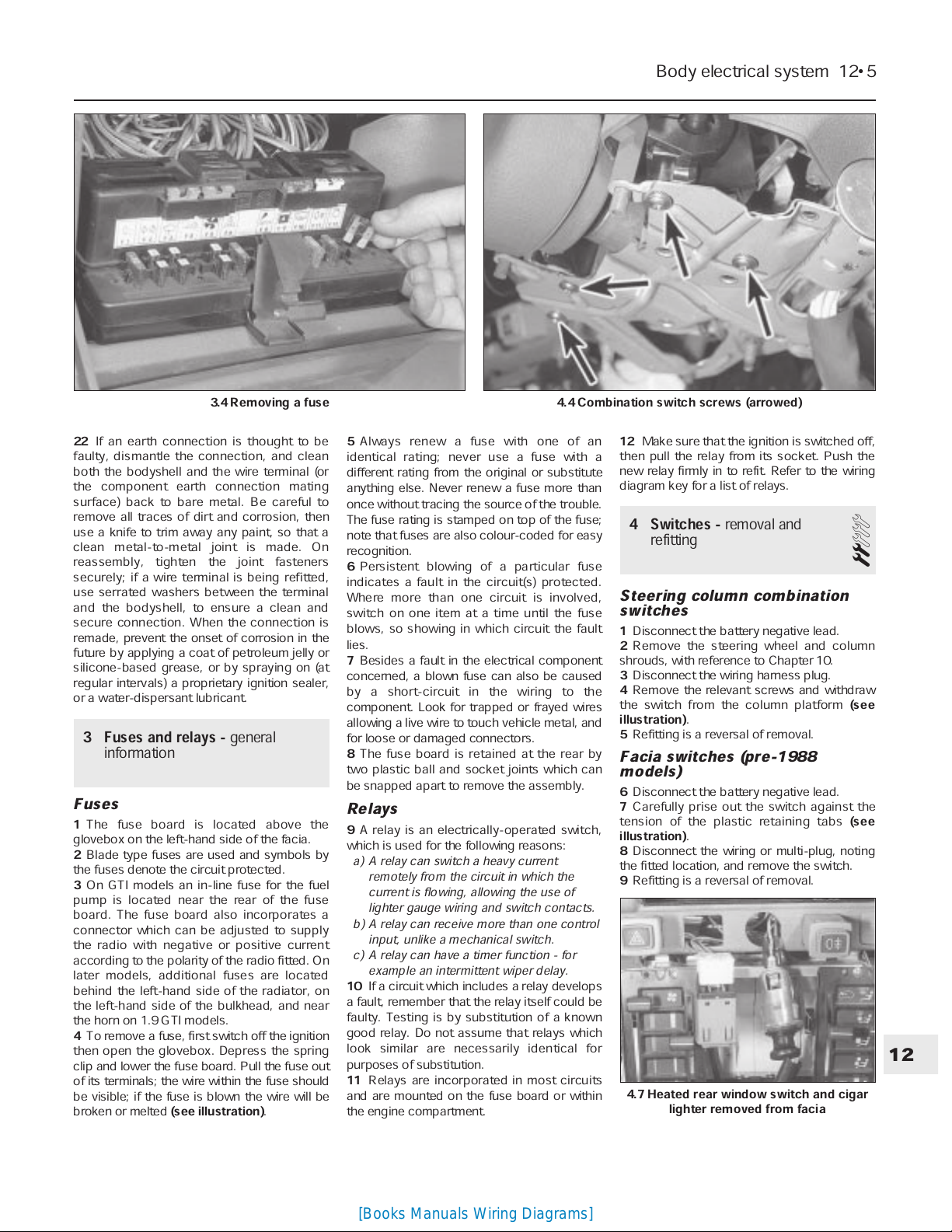
4
To remove a fuse, first switch off the ignition
then open the glovebox. Depress the spring
clip and lower the fuse board. Pull the fuse out
of its terminals; the wire within the fuse should
be visible; if the fuse is blown the wire will be
broken or melted
(see illustration)
.
5
Always renew a fuse with one of an
identical rating; never use a fuse with a
different rating from the original or substitute
anything else. Never renew a fuse more than
once without tracing the source of the trouble.
The fuse rating is stamped on top of the fuse;
note that fuses are also colour-coded for easy
recognition.
6
Persistent blowing of a particular fuse
indicates a fault in the circuit(s) protected.
Where more than one circuit is involved,
switch on one item at a time until the fuse
blows, so showing in which circuit the fault
lies.
7
Besides a fault in the electrical component
concerned, a blown fuse can also be caused
by a short-circuit in the wiring to the
component. Look for trapped or frayed wires
allowing a live wire to touch vehicle metal, and
for loose or damaged connectors.
8
The fuse board is retained at the rear by
two plastic ball and socket joints which can
be snapped apart to remove the assembly.
Relays
9
A relay is an electrically-operated switch,
which is used for the following reasons:
a) A relay can switch a heavy current
remotely from the circuit in which the
current is flowing, allowing the use of
lighter gauge wiring and switch contacts.
b) A relay can receive more than one control
input, unlike a mechanical switch.
c) A relay can have a timer function - for
example an intermittent wiper delay.
10
If a circuit which includes a relay develops
a fault, remember that the relay itself could be
faulty. Testing is by substitution of a known
good relay. Do not assume that relays which
look similar are necessarily identical for
purposes of substitution.
11
Relays are incorporated in most circuits
and are mounted on the fuse board or within
the engine compartment.
12
Make sure that the ignition is switched off,
then pull the relay from its socket. Push the
new relay firmly in to refit. Refer to the wiring
diagram key for a list of relays.
4 Switches -
removal and
refitting
2
Steering column combination
switches
1
Disconnect the battery negative lead.
2
Remove the steering wheel and column
shrouds, with reference to Chapter 10.
3
Disconnect the wiring harness plug.
4
Remove the relevant screws and withdraw
the switch from the column platform
(see
illustration)
.
5
Refitting is a reversal of removal.
Facia switches (pre-1988
models)
6
Disconnect the battery negative lead.
7
Carefully prise out the switch against the
tension of the plastic retaining tabs
(see
illustration)
.
8
Disconnect the wiring or multi-plug, noting
the fitted location, and remove the switch.
9
Refitting is a reversal of removal.
Body electrical system 12•5
12
4.7 Heated rear window switch and cigar
lighter removed from facia
3.4 Removing a fuse 4.4 Combination switch screws (arrowed)
[Books Manuals Wiring Diagrams]

Facia switches (1988 models
onward)
10
Disconnect the battery negative lead.
11
Open the ashtray.
12
Unclip the bottom of the clock surround
(where fitted) and remove it.
13
Remove the screws from the bottom of
the switch panel, then insert lengths of
welding rod (or similar) into the special holes,
and remove the switch panel surround
(see
illustrations)
.
14
The individual switches may now be
removed by inserting two small screwdrivers
in the slots on each side of the switch,
extracting the switch, and disconnecting the
wiring.
15
Refitting is a reversal of removal.
Instrument panel rheostat -
removal and refitting
16
Prise the rheostat from the steering
column lower shroud, and disconnect the
wiring
(see illustration)
.
17
Refitting is a reversal of removal.
Reversing light switch - removal
and refitting
18
Disconnect the wiring and unscrew the
switch from the top or side of the transmission
housing
(see illustration)
. Remove the
washer.
19
Refitting is a reversal of removal, but
renew the washer if necessary
Courtesy light switch
20
Disconnect the battery negative lead.
21
The switch is secured to the door pillar by
a self-tapping screw. Extract the screw and
withdraw the switch and leads
(see
illustration)
.
22
If the leads are disconnected, tape them
to the pillar to prevent them from slipping
inside the pillar cavity.
23
It is recommended that the metal contacts
of the switch are smeared with petroleum jelly
as a precaution against corrosion.
24
Refit by reversing the removal operation.
Glovebox illumination switch
25
Disconnect the battery negative lead.
26
Open the glovebox then reach up and
release the switch from the inside of the facia
(see illustration)
.
27
Disconnect the wiring.
28
Refitting is a reversal of removal.
Ignition switch/steering column
lock
29
Refer to Chapter 10.
Handbrake warning switch
30
Move the front seats fully forward then
remove the screw and lift the cover from the
handbrake lever.
31
With the handbrake applied, remove the
mounting screw, withdraw the switch and
disconnect the wiring
(see illustration)
.
32
Refitting is a reversal of removal.
Brake stop light switch
33
Disconnect the battery negative lead.
34
Remove the lower facia panel from the
steering column.
35
Disconnect the two wires
(see
illustration)
.
12•6 Body electrical system
4.13a On later models, remove the switch
panel lower screws . . .
4.13b Insert lengths of rod into the special
holes . . .
4.13c . . . and withdraw the switch panel
surround
4.21 Removing a courtesy light switch 4.26 Glovebox illumination switch 4.31 Handbrake warning light switch
(arrowed)
4.16 Instrument illumination rheostat 4.18 Reversing light switch location on the
BH3 transmission
[Books Manuals Wiring Diagrams]
36
Unscrew the locknut nearest the pedal,
and withdraw the switch from the bracket.
37
Refitting is a reversal of removal, but
adjust the locknuts so that the distance
between the end of the switch threaded body
and the pedal (fully released) is 3.5 mm.
5 Instrument panel
- removal
and refitting
2
Removal
Pre-1988 models
1
Disconnect the battery negative lead.
2
On non-GTI models, using an Allen key,
unscrew the two upper retaining screws at
each end of the panel surround
(see
illustration)
.
3
On GTI models, remove the plastic tray
from the top of the panel surround by pushing
it towards the windscreen to release the
securing clips. Unscrew the now-exposed
panel surround securing screw.
4
Unscrew the two lower surround retaining
screws located either side of the steering
column shroud
(see illustration)
.
5
Withdraw the surround from the facia.
6
Pull out the instrument panel while
depressing the lower spring supports, then
disconnect the multi-plugs and speedometer
cable
(see illustrations)
.
7
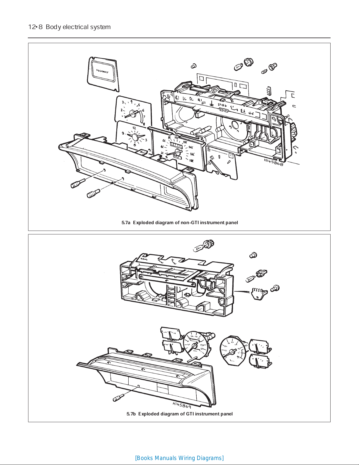
If necessary, the individual components can
be removed for repair or renewal
(see
illustrations)
.
1988 models onward
8
Disconnect the battery negative lead.
9
Remove the trapezium-shaped coin
compartment or cover from the top of the
facia by lifting the bottom edge.
10
Pull off the heater control knobs, using
card or thick cloth and pliers on the central
bars.
11
Remove the screws beneath the outer
control knobs, and withdraw the upper front
panel surround.
12
Remove the screws and withdraw the
visor trim from the instrument panel.
Body electrical system 12•7
12
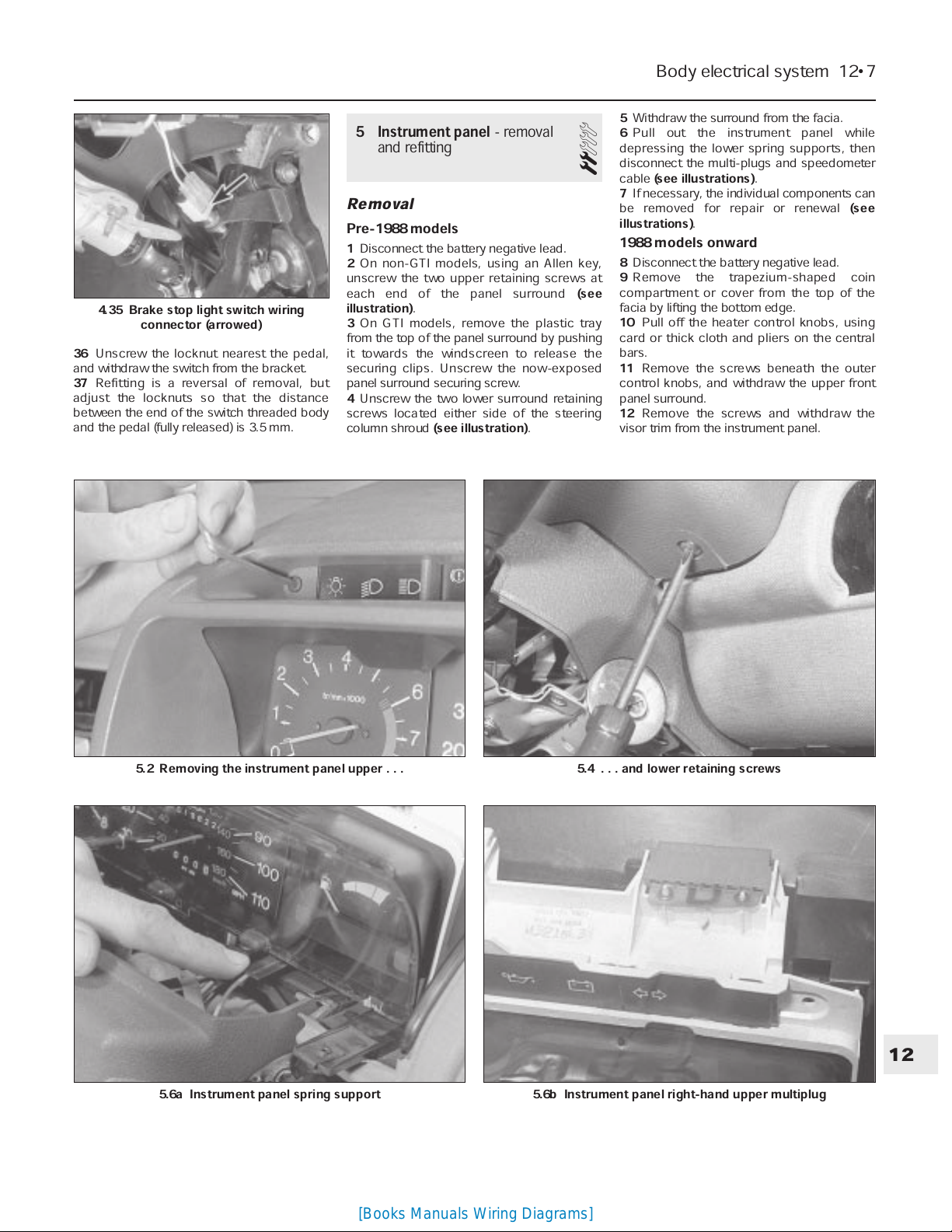
4.35 Brake stop light switch wiring
connector (arrowed)
5.6a Instrument panel spring support 5.6b Instrument panel right-hand upper multiplug
5.2 Removing the instrument panel upper . . . 5.4 . . . and lower retaining screws
[Books Manuals Wiring Diagrams]
12•8 Body electrical system
5.7a Exploded diagram of non-GTI instrument panel
5.7b Exploded diagram of GTI instrument panel
[Books Manuals Wiring Diagrams]
13
Remove the screws and withdraw the
centre vents.
14
Using a screwdriver through the steering
column lower shroud, unscrew the visor
locating studs.
15
Remove the side screw, then lift away the
visor.
16
Remove the mounting screws from each
side of the instrument panel
(see illustration)
.
17
Tilt the instrument panel and disconnect
the wiring plugs, noting their locations
(see
illustration)
.
18
Disconnect the speedometer cable by
squeezing the end fitting. Remove the
instrument panel. If necessary, the individual
components can be removed for repair or
renewal.
Refitting
19
On all models, refitting is a reversal of
removal.
6 Clock -
removal and refitting
1
Removal
Pre-1988 models
1
Disconnect the battery negative lead.
2
Using a small screwdriver, carefully prise
the clock from its location in the facia.
3
Disconnect the clock wiring and remove the
unit.
1988 models onward
4
Disconnect the battery negative lead.
5
Remove the trapezium-shaped coin
compartment or cover from the top of the
facia by lifting the bottom edge.
6
Pull off the heater control knobs, using card
or thick cloth and pliers on the central bars.
7
Remove the screws beneath the control
knobs, and withdraw the upper front panel
surround.
8
Open and remove the ashtray.
9
Unclip the bottom of the clock surround
and remove it.
10
Remove the oddments tray, or if fitted, the
radio, as described in Section 22.
11
Remove the screws and withdraw the
lower front panel surround by releasing the
bottom edge first.
12
Disconnect the wiring plug from the rear
of the clock, then release the clock from the
lower front panel surround.
Refitting
13
On all models, refitting is a reversal of
removal.
7 Speedometer cable
- renewal
2
1
Disconnect the speedometer cable from
the transmission by removing the retaining
bolt or rubber plug.
2
Remove the instrument panel, as described
in Section 5.
3
Prise the rubber grommet from the
bulkhead beneath the facia
(see
illustrations)
.
4
Remove the retaining clips, where fitted,
and withdraw the speedometer cable.
5
Refitting is a reversal of removal.
8 Bulbs (exterior lights)
-
renewal
2
General
1
With all light bulbs, remember that if they
have just been in use, they may be very hot.
Switch off the power before renewing a bulb.
2
With quartz halogen bulbs (headlights and
similar applications), use a tissue or clean
cloth when handling the bulb; do not touch
the bulb glass with the fingers. Even small
quantities of grease from the fingers will
cause blackening and premature failure. If a
bulb is accidentally touched, clean it with
methylated spirit and a clean rag.
3
Unless otherwise stated, fit the new bulb by
reversing the removal operations.
Bulb renewal
Headlight
4
Where fitted, remove the cover from the
rear of the headlight.
5
Pull the connector from the bulb
(see
illustration)
.
6
Remove the rubber cover, noting that the
water drain hole is at the bottom
(see
illustration)
.
Body electrical system 12•9
12
5.16 Removing the instrument panel
mounting screws on later models . . .
5.17 . . . and disconnecting the wiring
plugs
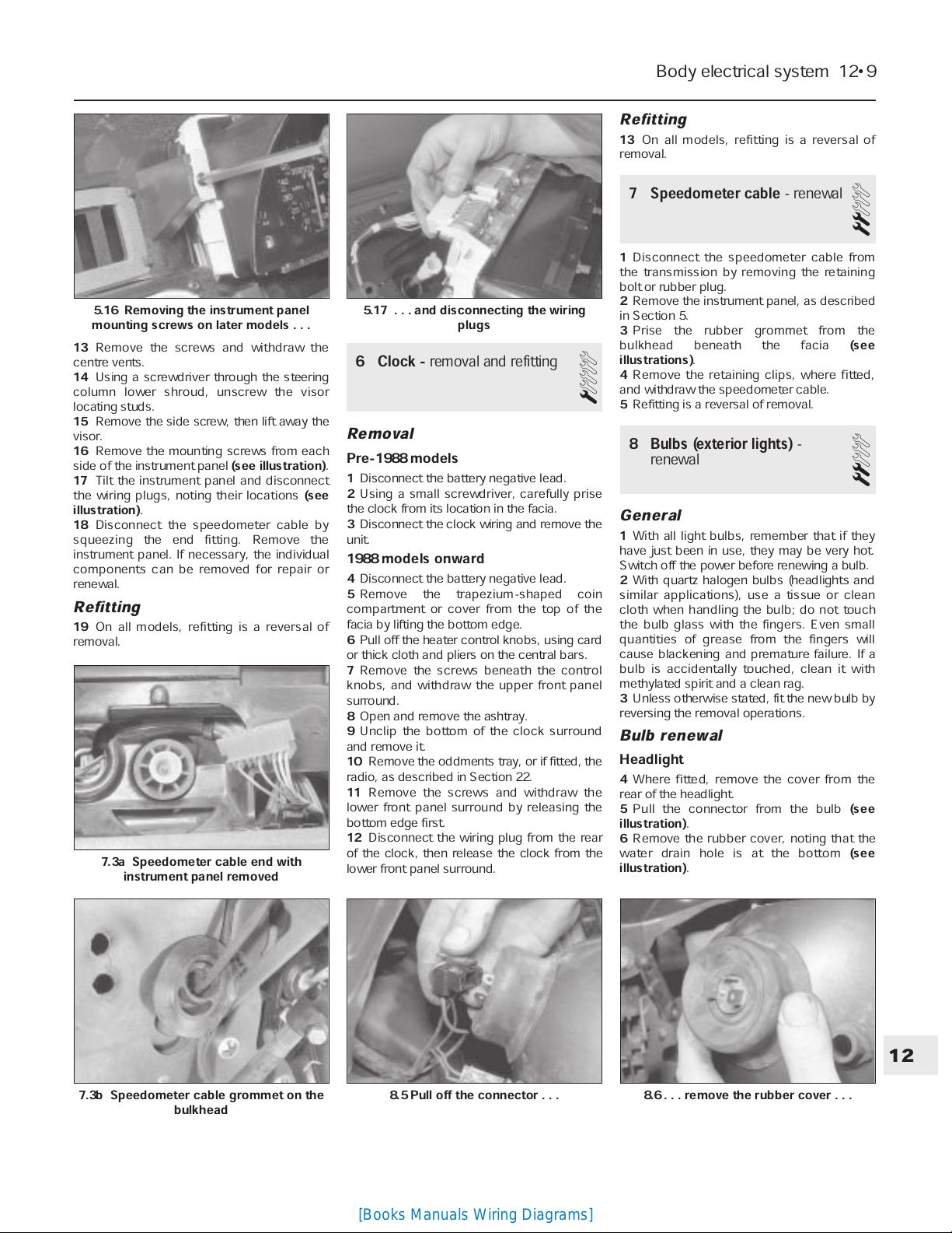
7.3a Speedometer cable end with
instrument panel removed
7.3b Speedometer cable grommet on the
bulkhead
8.5 Pull off the connector . . . 8.6 . . . remove the rubber cover . . .
[Books Manuals Wiring Diagrams]
 Loading...