

Peugeot 205 User Manual
Peugeot 205
Service and Repair Manual
Models covered
All Peugeot 205 models with petrol engines (inc. GTi, Cabriolet, Automatic & special/limited editions)
954 cc, 1124 cc, 1360 cc, 1580 cc & 1905 cc
Covers mechanical features of Vans
Does not cover diesel engine or T16 Turbo models
A K Legg LAE MIMI and John S Mead
© Haynes Publishing 1996
A book in the Haynes Service and Repair Manual Series
All rights reserved. No part of this book may be reproduced or
transmitted in any form or by any means, electronic or
mechanical, including photocopying, recording or by any
information storage or retrieval system, without permission in
writing from the copyright holder.
ISBN 1 85960 189 8
British Library Cataloguing in Publication Data
A catalogue record for this book is available from the British Library.
Printed by J. H. Haynes & Co. Ltd, Sparkford, Nr Yeovil,
Somerset BA22 7JJ, England
Haynes Publishing
Sparkford Nr Yeovil
Somerset BA22 7JJ England
Haynes North America, Inc
861 Lawrence Drive, Newbury Park
California 91320 USA
Editions Haynes S.A
147/149, rue Saint Honoré, 75001 PARIS, France
Haynes Publishing Nordiska AB
Fyrisborgsgatan 5, 754 50 Uppsala, Sverige
(932 - 272 - 10Y12)

LIVING WITH YOUR PEUGEOT 205
Introduction Page 0•4
Safety First! Page 0•5
ROADSIDE REPAIRS
Introduction Page 0•6
If your car won’t start Page 0•6
Jump starting Page 0•7
Wheel changing Page 0•8
Identifying leaks Page 0•9
Towing Page 0•9
WEEKLY CHECKS
Introduction Page 0•10
Underbonnet check points Page 0•10
Engine oil level Page 0•11
Coolant level Page 0•11
Brake fluid level Page 0•12
Power steering fluid level Page 0•12
Screen washer fluid level Page 0•13
Battery Page 0•13
Tyre condition and pressure Page 0•14
Wiper blades Page 0•15
Bulbs and fuses Page 0•15
Lubricants and fluids Page 0•16
Tyre pressures Page 0•16
MAINTENANCE
Routine Maintenance and Servicing
Servicing Specifications Page 1•2
Maintenance schedule Page 1•3
Maintenance procedures Page 1•8
Contents

REPAIRS & OVERHAUL
Engine and Associated Systems
XV, XW and XY engines in-car repair procedures Page 2A•1
XU series engine in-car repair procedures Page 2B•1
TU series engine in-car repair procedures Page 2C•1
Engine removal and overhaul procedures Page 2D•1
Cooling, heating and air conditioning systems Page 3•1
Fuel system - carburettor engines Page 4A•1
Fuel system - single-point fuel injection engines Page 4B•1
Fuel system - multi-point fuel injection engines Page 4C•1
Exhaust and emission control and exhaust systems Page 4D•1
Starting and charging systems Page 5A•1
Ignition system Page 5B•1
Transmission
Clutch Page 6•1
Manual transmission Page 7A•1
Automatic transmission Page 7B•1
Driveshafts Page 8•1
Brakes and Suspension
Braking system Page 9•1
Suspension and steering Page 10•1
Body Equipment
Bodywork and fittings Page 11•1
Body electrical system Page 12•1
Wiring Diagrams Page 12•15
REFERENCE
Dimensions and weights Page REF•1
Conversion factors Page REF•2
Buying spare parts Page REF•3
Vehicle identification Page REF•3
General repair procedures Page REF•4
Jacking and vehicle support Page REF•5
Radio/cassette anti-theft system Page REF•5
Tools and working facilities Page REF•6
MOT test checks Page REF•8
Fault finding Page REF•12
Glossary of technical terms Page REF•20
Index Page REF•25
Contents
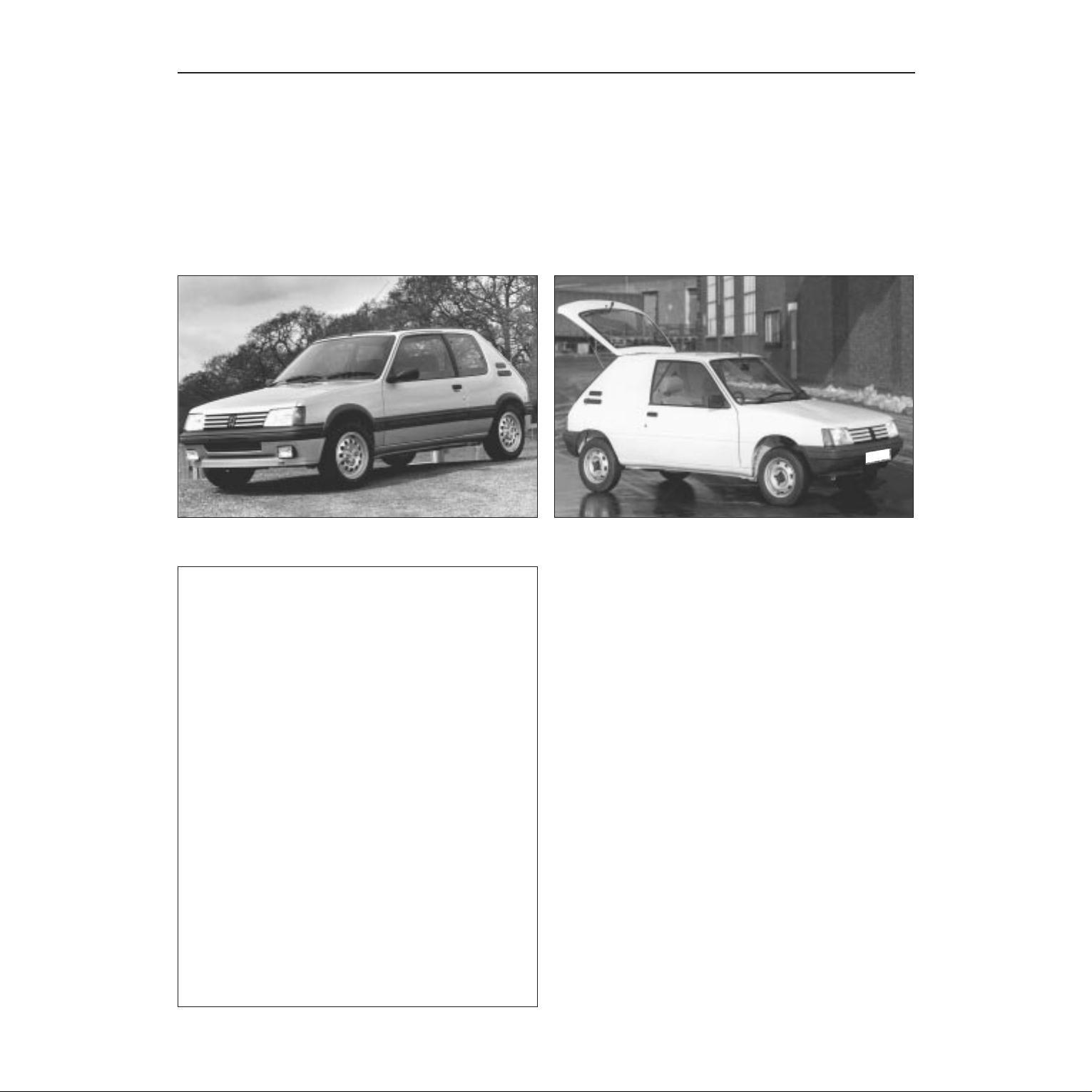
The Peugeot 205 was introduced in the UK in September 1983 as a
five-door Hatchback with a transversely-mounted engine and transmission assembly driving the front wheels. The suspension is of front
coil springs and rear transverse torsion bars.
Three engine sizes were originally available, featuring a chain driven
overhead camshaft design mounted directly over the transmission. The
GTi was introduced in the Spring of 1984 and was fitted with a
belt-driven overhead camshaft engine with a side-mounted
transmission. The GTI engine is equipped with an electronically
controlled fuel injection system.
In October 1984 three-door versions became available, with an X
series designation, in addition to the three-door GTI. Van versions were
introduced in June 1985, together with the limited edition Lacoste,
based on the GT version. In September 1985 the XT was introduced,
being a three-door version of the GT, and at the same time the 954 cc
XL three-door was introduced, having a higher specification than the
XE. The 1580 cc Automatic was introduced in April 1986 at the same
time as the Cabriolet CTI. The XS replaced the XT in July 1986, at
which time the limited edition Junior, based on the XE, became
available. The 1.9 GTI was introduced in August 1986, and at the same
time dim-dip headlights and rear seat belts were fitted as standard. In
December 1987 the new TU engines and MA transmissions were fitted
to all except fuel injection, diesel and automatic models.
Latest models feature single- and multi-point fuel injection, with full
emission control equipment and a sophisticated engine management
system.
0•4 Introduction
Peugeot 205 GTi Peugeot 205 van
Your Peugeot 205 Manual
The aim of this manual is to help you get the best value from your
vehicle. It can do so in several ways. It can help you decide what work
must be done (even should you choose to get it done by a garage),
provide information on routine maintenance and servicing, and give a
logical course of action and diagnosis when random faults occur.
However, it is hoped that you will use the manual by tackling the work
yourself. On simpler jobs it may even be quicker than booking the car
into a garage and going there twice, to leave and collect it. Perhaps
most important, a lot of money can be saved by avoiding the costs a
garage must charge to cover its labour and overheads.
The manual has drawings and descriptions to show the function of
the various components so that their layout can be understood. Then
the tasks are described and photographed in a clear step-by-step
sequence.
Acknowledgements
Thanks are due to Champion Spark Plug, who supplied the illustrations
showing spark plug condition. Certain illustrations are the copyright of
Peugeot Talbot Motor Company Limited, and are used with their
permission. Thanks are also due to Sykes-Pickavant Limited, who
provided some of the workshop tools, and to Duckhams Oils who
provided lubrication data, also to all those people at Sparkford who
helped in the production of this manual.
We take great pride in the accuracy of information given in this
manual, but vehicle manufacturers make alterations and design
changes during the production run of a particular vehicle of which
they do not inform us. No liability can be accepted by the authors
or publishers for loss, damage or injury caused by any errors in, or
omissions from the information given.
The Peugeot 205 Team
Haynes manuals are produced by dedicated and
enthusiastic people working in close co-operation. The
team responsible for the creation of this book included:
Authors Andy Legg
John Mead
Sub-editors Carole Turk
Editor & Page Make-up Steve Churchill
Workshop manager Paul Buckland
Photo Scans John Martin
Paul Tanswell
Cover illustration & Line Art Roger Healing
Wiring diagrams Matthew Marke
We hope the book will help you to get the maximum
enjoyment from your car. By carrying out routine
maintenance as described you will ensure your car’s
reliability and preserve its resale value.
Safety first! 0•5
Working on your car can be dangerous.
This page shows just some of the potential
risks and hazards, with the aim of creating a
safety-conscious attitude.
General hazards
Scalding
• Don’t remove the radiator or expansion
tank cap while the engine is hot.
• Engine oil, automatic transmission fluid or
power steering fluid may also be dangerously
hot if the engine has recently been running.
Burning
• Beware of burns from the exhaust system
and from any part of the engine. Brake discs
and drums can also be extremely hot
immediately after use.
Crushing
• When working under or near
a raised vehicle,
always
supplement the
jack with axle
stands, or use
drive-on
ramps.
Never
venture
under a car which
is only supported by a jack.
• Take care if loosening or tightening hightorque nuts when the vehicle is on stands.
Initial loosening and final tightening should
be done with the wheels on the ground.
Fire
• Fuel is highly flammable; fuel vapour is
explosive.
• Don’t let fuel spill onto a hot engine.
• Do not smoke or allow naked lights
(including pilot lights) anywhere near a
vehicle being worked on. Also beware of
creating sparks
(electrically or by use of tools).
• Fuel vapour is heavier than air, so don’t
work on the fuel system with the vehicle over
an inspection pit.
• Another cause of fire is an electrical
overload or short-circuit. Take care when
repairing or modifying the vehicle wiring.
• Keep a fire extinguisher handy, of a type
suitable for use on fuel and electrical fires.
Electric shock
• Ignition HT
voltage can be
dangerous,
especially to
people with heart
problems or a
pacemaker. Don’t
work on or near the
ignition system with
the engine running or
the ignition switched on.
• Mains voltage is also dangerous. Make
sure that any mains-operated equipment is
correctly earthed. Mains power points should
be protected by a residual current device
(RCD) circuit breaker.
Fume or gas intoxication
• Exhaust fumes are
poisonous; they often
contain carbon
monoxide, which is
rapidly fatal if inhaled.
Never run the
engine in a
confined space
such as a garage
with the doors shut.
• Fuel vapour is also
poisonous, as are the vapours from some
cleaning solvents and paint thinners.
Poisonous or irritant substances
• Avoid skin contact with battery acid and
with any fuel, fluid or lubricant, especially
antifreeze, brake hydraulic fluid and Diesel
fuel. Don’t syphon them by mouth. If such a
substance is swallowed or gets into the eyes,
seek medical advice.
• Prolonged contact with used engine oil can
cause skin cancer. Wear gloves or use a
barrier cream if necessary. Change out of oilsoaked clothes and do not keep oily rags in
your pocket.
• Air conditioning refrigerant forms a
poisonous gas if exposed to a naked flame
(including a cigarette). It can also cause skin
burns on contact.
Asbestos
• Asbestos dust can cause cancer if inhaled
or swallowed. Asbestos may be found in
gaskets and in brake and clutch linings.
When dealing with such components it is
safest to assume that they contain asbestos.
Special hazards
Hydrofluoric acid
• This extremely corrosive acid is formed
when certain types of synthetic rubber, found
in some O-rings, oil seals, fuel hoses etc, are
exposed to temperatures above 400
0
C. The
rubber changes into a charred or sticky
substance containing the acid. Once formed,
the acid remains dangerous for years. If it
gets onto the skin, it may be necessary to
amputate the limb concerned.
• When dealing with a vehicle which has
suffered a fire, or with components salvaged
from such a vehicle, wear protective gloves
and discard them after use.
The battery
• Batteries contain sulphuric acid, which
attacks clothing, eyes and skin. Take care
when topping-up or carrying the battery.
• The hydrogen gas given off by the battery
is highly explosive. Never cause a spark or
allow a naked light nearby. Be careful when
connecting and disconnecting battery
chargers or jump leads.
Air bags
• Air bags can cause injury if they go off
accidentally. Take care when removing the
steering wheel and/or facia. Special storage
instructions may apply.
Diesel injection equipment
• Diesel injection pumps supply fuel at very
high pressure. Take care when working on
the fuel injectors and fuel pipes.
Warning: Never expose the hands,
face or any other part of the body
to injector spray; the fuel can
penetrate the skin with potentially fatal
results.
Remember...
DO
• Do use eye protection when using power
tools, and when working under the vehicle.
• Do wear gloves or use barrier cream to
protect your hands when necessary.
• Do get someone to check periodically
that all is well when working alone on the
vehicle.
• Do keep loose clothing and long hair well
out of the way of moving mechanical parts.
• Do remove rings, wristwatch etc, before
working on the vehicle – especially the
electrical system.
• Do ensure that any lifting or jacking
equipment has a safe working load rating
adequate for the job.
A few tips
DON’T
• Don’t attempt to lift a heavy component
which may be beyond your capability – get
assistance.
• Don’t rush to finish a job, or take
unverified short cuts.
• Don’t use ill-fitting tools which may slip
and cause injury.
• Don’t leave tools or parts lying around
where someone can trip over them. Mop
up oil and fuel spills at once.
• Don’t allow children or pets to play in or
near a vehicle being worked on.
0•6 Roadside repairs
The following pages are intended to help in dealing with
common roadside emergencies and breakdowns. You will find
more detailed fault finding information at the back of the
manual, and repair information in the main chapters.
If your car won’t start
and the starter motor
doesn’t turn
M If it’s a model with automatic transmission, make sure the
selector is in ‘P’ or ‘N’.
M Open the bonnet and make sure that the battery terminals
are clean and tight.
M Switch on the headlights and try to start the engine. If the
headlights go very dim when you’re trying to start, the
battery is probably flat. Get out of trouble by jump starting
(see next page) using a friend’s car.
If your car won’t start
even though the starter
motor turns as normal
M Is there fuel in the tank?
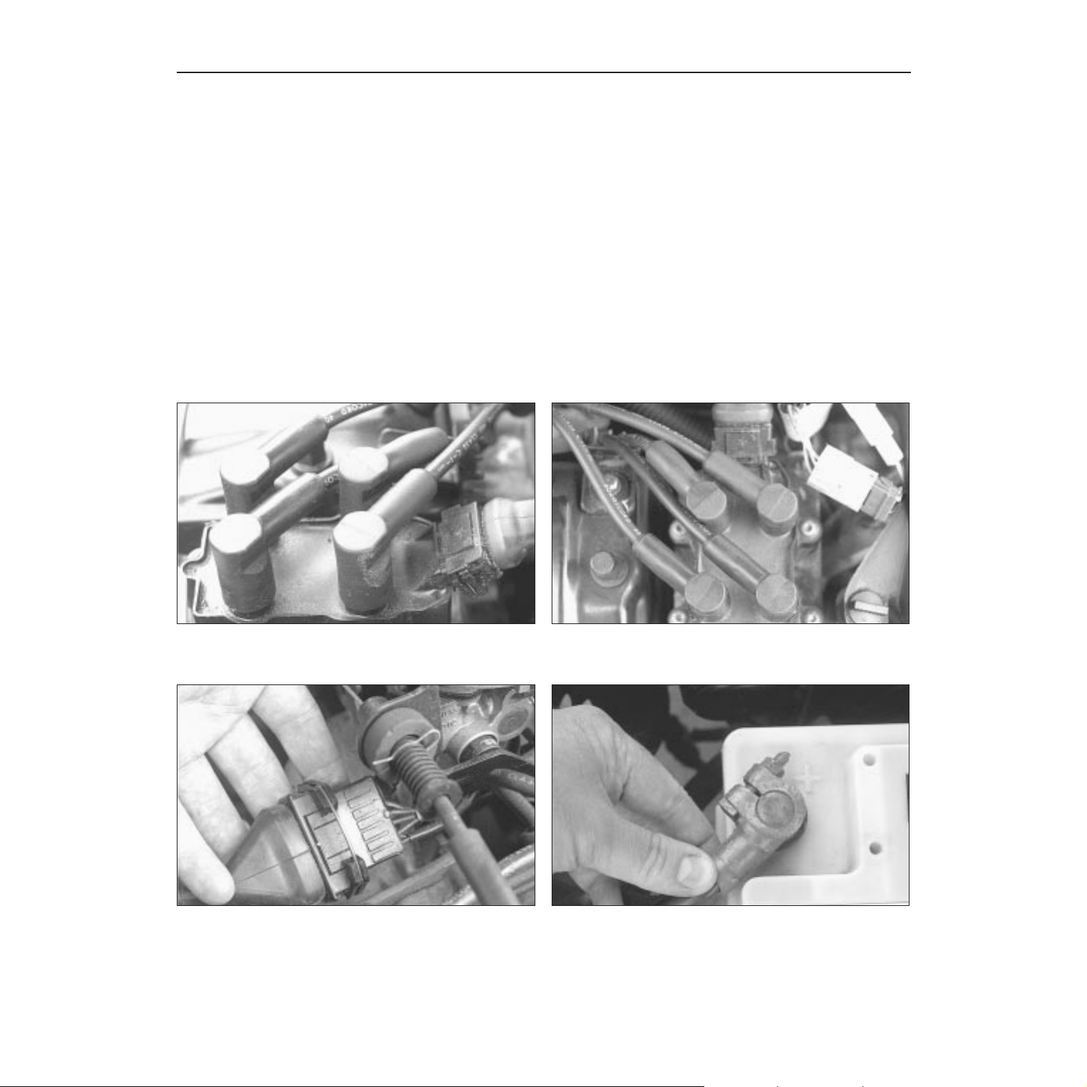
M Is there moisture on electrical components under the
bonnet? Switch off the ignition, then wipe off any obvious
dampness with a dry cloth. Spray a water-repellent aerosol
product (WD-40 or equivalent) on ignition and fuel system
electrical connectors like those shown in the photos.
Pay special attention to the ignition coil wiring connector
and HT leads. (Note that Diesel engines don’t normally
suffer from damp.)
Check the security of all the fuel injection system wiring
connectors (where applicable).
C
Check the security and condition of the battery terminals.
D
Check that all ignition wiring connectors such as this at the
distributor are secure and spray with water dispersant if
necessary.
B
Check that the spark plug HT leads are securely connected by
pushing them home
A
Check that electrical connections are secure (with the ignition switched off) and spray them
with a water dispersant spray like WD40 if you suspect a problem due to damp
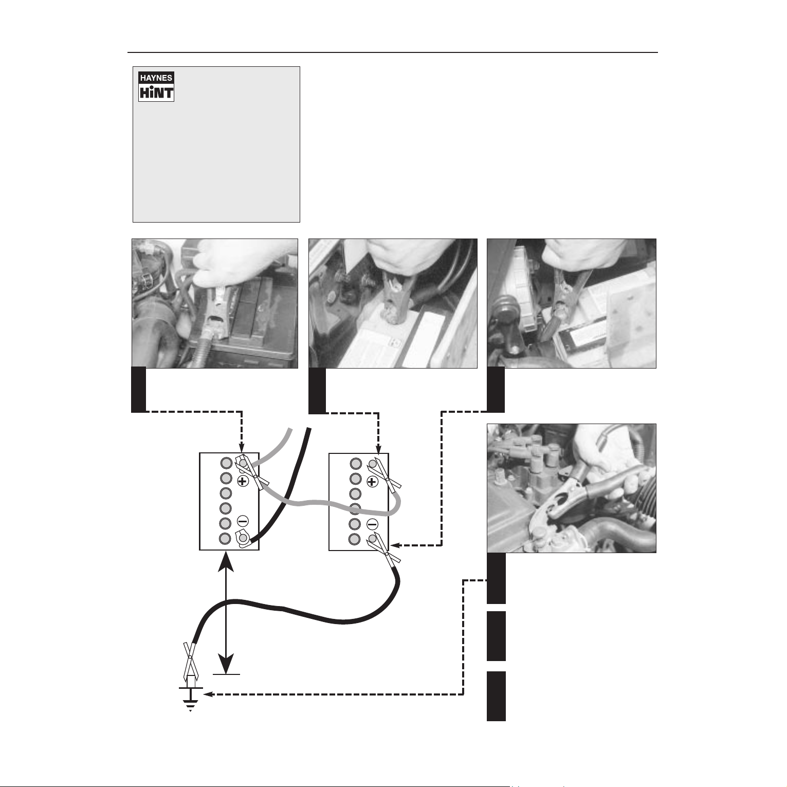
Roadside repairs 0•7
When jump-starting a car using a
booster battery, observe the following
precautions:
4 Before connecting the booster
battery, make sure that the ignition is
switched off.
4 Ensure that all electrical equipment
(lights, heater, wipers, etc) is
switched off.
4 Make sure that the booster battery is
the same voltage as the discharged
one in the vehicle.
4 If the battery is being jump-started
from the battery in another vehicle,
the two vehcles MUST NOT TOUCH
each other.
4 Make sure that the transmission is in
neutral (or PARK, in the case of
automatic transmission).
Jump starting will get you out
of trouble, but you must correct
whatever made the battery go
flat in the first place. There are
three possibilities:
1
The battery has been drained by
repeated attempts to start, or by
leaving the lights on.
2
The charging system is not working
properly (alternator drivebelt slack
or broken, alternator wiring fault or
alternator itself faulty).
3
The battery itself is at fault
(electrolyte low, or battery worn out).
Connect one end of the red jump lead to
the positive (+) terminal of the flat
battery
Connect the other end of the red lead to
the positive (+) terminal of the booster
battery.
Connect one end of the black jump lead
to the negative (-) terminal of the
booster battery
Connect the other end of the black
jump lead to a bolt or bracket on the
engine block, well away from the
battery, on the vehicle to be started.
1
2
3
4
Make sure that the jump leads will not
come into contact with the fan, drivebelts or other moving parts of the
engine.
5
Start the engine using the booster
battery, then with the engine running at
idle speed, disconnect the jump leads in
the reverse order of connection.
6
Jump starting
0•8 Roadside repairs
Wheel changing
Some of the details shown here will vary
according to model. For instance, the location
of the spare wheel and jack is not the same
on all cars. However, the basic principles
apply to all vehicles.
M When a puncture occurs, stop as soon
as it is safe to do so.
M Park on firm level ground, if possible,
and well out of the way of other traffic.
M Use hazard warning lights if necessary.
M If you have one, use a warning triangle to
alert other drivers of your presence.
M Apply the handbrake and engage first or
reverse gear.
M Chock the wheel diagonally opposite the
one being removed – a couple of large
stones will do for this.
M If the ground is soft, use a flat piece of
wood to spread the load under the foot
of the jack.
Finally...
M Remove the wheel chocks. Stow the
jack and tools in the appropriate
locations in the car.
M Don’t leave the spare wheel cradle
empty and unsecured – it could drop
onto the ground while the car is moving.
M Check the tyre pressure on the wheel
just fitted. If it is low, or if you don’t have
a pressure gauge with you, drive slowly
to the nearest garage and inflate the tyre
to the correct pressure. Have the
damaged tyre or wheel repaired, or
renew it, as soon as possible.
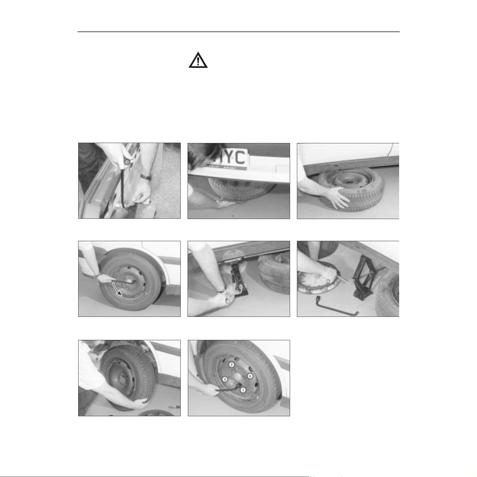
From inside the boot area, use the
wheelbrace to lower the spare wheel
cradle.
Slide the spare wheel out from the
underside of the car.
For safety in the event of the jack
slipping, position the spare wheel under
the sill, close to the jacking point.
Remove the wheel trim (where fitted)
then slacken each wheel bolt by a half
turn.
Locate the jack below the reinforced
jacking point and on firm ground (don’t
jack the car at any other point on the sill).
Turn the jack handle clockwise until the
wheel is raised clear of the ground,
remove the bolts and lift the wheel clear.
Position the spare wheel and fit the
bolts. Tighten moderately with the wheelbrace, then lower the car to the ground.
Tighten the wheel bolts in the sequence
shown, fit the wheel trim, and secure the
punctured wheel in the spare wheel
cradle.
Changing the wheel
Preparation
Warning: Do not change a wheel in a situation where you risk being hit by
other traffic. On busy roads, try to stop in a lay-by or a gateway. Be wary of
passing traffic while changing the wheel – it is easy to become distracted by
the job in hand.
1
2 3
654
7 8
Roadside repairs 0•9
When all else fails, you may find yourself
having to get a tow home – or of course you
may be helping somebody else. Long-distance
recovery should only be done by a garage or
breakdown service. For shorter distances, DIY
towing using another car is easy enough, but
observe the following points:
M Use a proper tow-rope – they are not
expensive. The vehicle being towed must
display an ‘ON TOW’ sign in its rear window.
M Always turn the ignition key to the ‘on’
position when the vehicle is being towed, so
that the steering lock is released, and that the
direction indicator and brake lights will work.
M Only attach the tow-rope to the towing
eyes provided.
M Before being towed, release the handbrake
and select neutral on the transmission.
M Note that greater-than-usual pedal
pressure will be required to operate the
brakes, since the vacuum servo unit is only
operational with the engine running.
M On models with power steering, greaterthan-usual steering effort will also be required.
M The driver of the car being towed must keep
the tow-rope taut at all times to avoid snatching.
M Make sure that both drivers know the route
before setting off.
M Only drive at moderate speeds and keep
the distance towed to a minimum. Drive
smoothly and allow plenty of time for slowing
down at junctions.
M On models with automatic transmission,
special precautions apply. If in doubt, do not
tow, or transmission damage may result.
M Do not tow BH type gearbox models with
the front wheels on the ground for long
distances, as the engine lubrication system
also supplies pressure-fed oil to the gears and
differential bearings Unnecessary wear may
occur if the car is towed with the engine
stopped.
Towing
Puddles on the garage floor or drive, or
obvious wetness under the bonnet or
underneath the car, suggest a leak that needs
investigating. It can sometimes be difficult to
decide where the leak is coming from,
especially if the engine bay is very dirty
already. Leaking oil or fluid can also be blown
rearwards by the passage of air under the car,
giving a false impression of where the
problem lies.
Warning: Most automotive oils
and fluids are poisonous. Wash
them off skin, and change out of
contaminated clothing, without
delay.
Identifying leaks
The smell of a fluid leaking
from the car may provide a
clue to what’s leaking. Some
fluids are distinctively
coloured. It may help to clean the car
carefully and to park it over some clean
paper overnight as an aid to locating the
source of the leak.
Remember that some leaks may only
occur while the engine is running.
Sump oil Gearbox oil
Brake fluid Power steering fluid
Oil from filter
Antifreeze
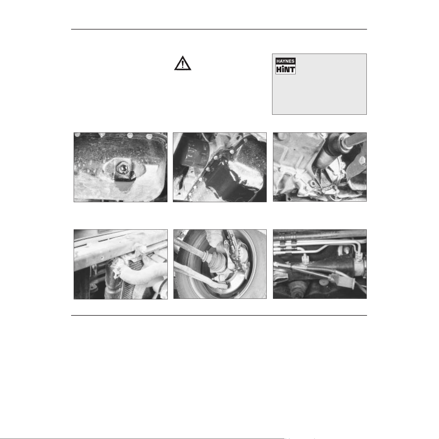
Engine oil may leak from the drain plug... ...or from the base of the oil filter.
Leaking antifreeze often leaves a crystalline
deposit like this.
Gearbox oil can leak from the seals at the
inboard ends of the driveshafts.
A leak occurring at a wheel is almost
certainly brake fluid.
Power steering fluid may leak from the pipe
connectors on the steering rack.
0•10 Weekly checks
There are some very simple checks which
need only take a few minutes to carry out, but
which could save you a lot of inconvenience
and expense.
These "Weekly checks" require no great skill
or special tools, and the small amount of time
they take to perform could prove to be very
well spent, for example;
M Keeping an eye on tyre condition and
pressures, will not only help to stop them
wearing out prematurely, but could also save
your life.
M
Many breakdowns are caused by electrical
problems. Battery-related faults are particularly
common, and a quick check on a regular basis
will often prevent the majority of
these.
M If your car develops a brake fluid leak, the
first time you might know about it is when
your brakes don't work properly. Checking
the level regularly will give advance warning of
this kind of problem.
M If the oil or coolant levels run low, the cost
of repairing any engine damage will be far
greater than fixing the leak, for example.
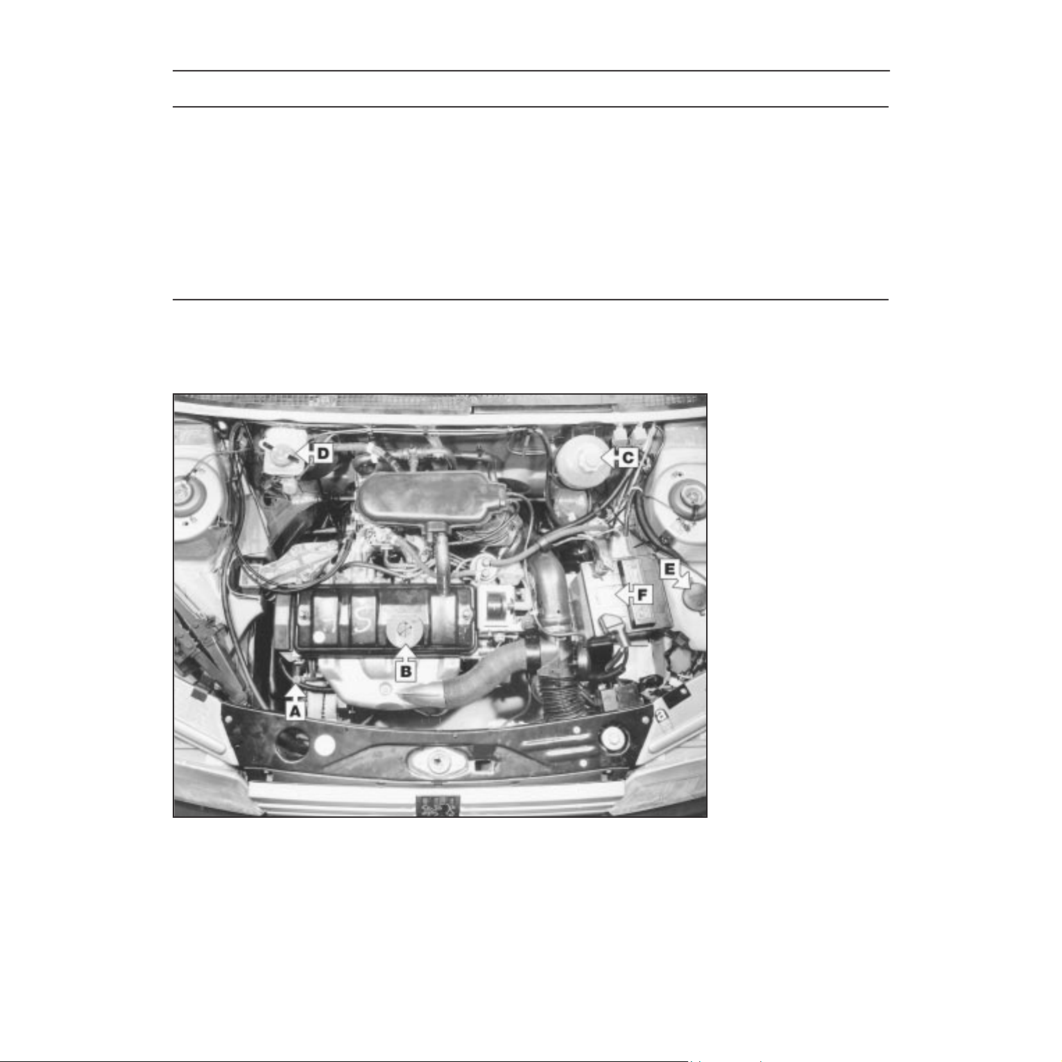
Introduction
§
TU series
Other engine similar
A
Engine oil level dipstick
B
Engine oil filler cap
C
Coolant expansion tank
D
Brake fluid reservoir
E
Screen washer fluid reservoir
F
Battery
Underbonnet check points
Weekly checks 0•11
Engine oil level
Before you start
4 Make sure that your car is on level ground.
4 Check the oil level before the car is driven,
or at least 5 minutes after the engine has been
switched off.
The correct oil
Modern engines place great demands on their
oil. It is very important that the correct oil for
your car is used (See “Lubricants, fluids and
tyre pressures”).
Car Care
l If you have to add oil frequently, you should
check whether you have any oil leaks. Place
some clean paper under the car overnight,
and check for stains in the morning. If there
are no leaks, the engine may be burning oil
(see “Fault Finding”)
.
l Always maintain the level between the
upper and lower dipstick marks (see photo 3).
If the level is too low severe engine damage
may occur. Oil seal failure may result if the
engine is overfilled by adding too much oil.
If the oil is checked
immediately after driving the
vehicle, some of the oil will
remain in the upper engine
components, resulting in an inaccurate
reading on the dipstick!
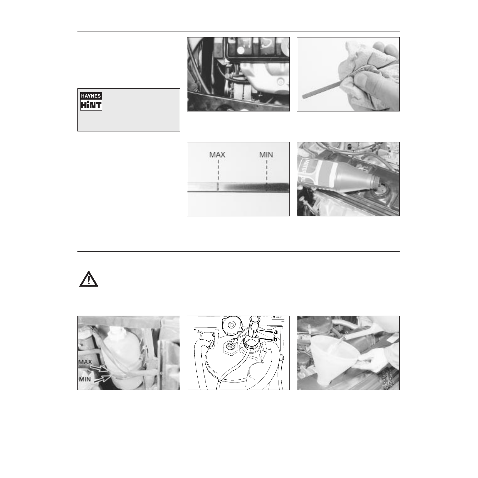
The dipstick top is often brightly coloured
for easy identification (see “Underbonnet
check points” on page 0•10 for exact
location). Withdraw the dipstick.
Using a clean rag or paper towel remove
all oil from the dipstick. Insert the clean
dipstick into the tube as far as it will go,
then withdraw it again.
Note the oil level on the end of the
dipstick, which should be between the
upper ("MAX") mark and lower ("MIN")
mark. Approximately 1.0 litre of oil will raise the
level from the lower mark to the upper mark.
Oil is added through the filler cap.
Unscrew the cap and top-up the level; a
funnel may help to reduce spillage. Add
the oil slowly, checking the level on the dipstick
often. Don’t overfill (see “Car Care” left).
1 2
3 4
Warning: DO NOT attempt to
remove the expansion tank
pressure cap when the engine
is hot, as there is a very great
risk of scalding. Do not leave
open containers of coolant
about, as it is poisonous.
Car Care
l With a sealed-type cooling system, adding
coolant should not be necessary on a regular
basis. If frequent topping-up is required, it is
likely there is a leak. Check the radiator, all
hoses and joint faces for signs of staining or
wetness, and rectify as necessary.
l It is important that antifreeze is used in the
cooling system all year round, not just during
the winter months. Don’t top-up with water
alone, as the antifreeze will become too
diluted.
Coolant level
The coolant level varies with engine
temperature. When cold, the coolant
level should be between the “MAX” and
“MIN” marks. When the engine is hot, the
level may rise slightly above the “MAX” mark.
Where the expansion tank has a level
indicator inside the expansion tank, the
coolant level should be between the
upper level indicator step (a) and lower step
(b). On all engines, when the coolant is hot,
the level may rise above the “MAX” mark or
level indicator step.
If topping-up is necessary, turn the
expansion tank cap slowly anti-clockwise
and wait until any pressure in the system
is released. Once any pressure is released,
unscrew it fully and lift it off. Add a mixture of
water and antifreeze through the filler neck until
the coolant is at the correct level. Refit the cap,
turning it clockwise as far as it will go to secure.
1
2 3
0•12 Weekly checks
Brake fluid level
Warning:
l Brake fluid can harm your
eyes and damage painted
surfaces, so use extreme
caution when handling and
pouring it.
l Do not use fluid that has
been standing open for some
time, as it absorbs moisture
from the air, which can cause a
dangerous loss of braking
effectiveness.
Safety First!
l If the reservoir requires repeated toppingup this is an indication of a fluid leak
somewhere in the system, which should be
investigated immediately.
l If a leak is suspected, the car should not be
driven until the braking system has been
checked. Never take any risks where brakes
are concerned.
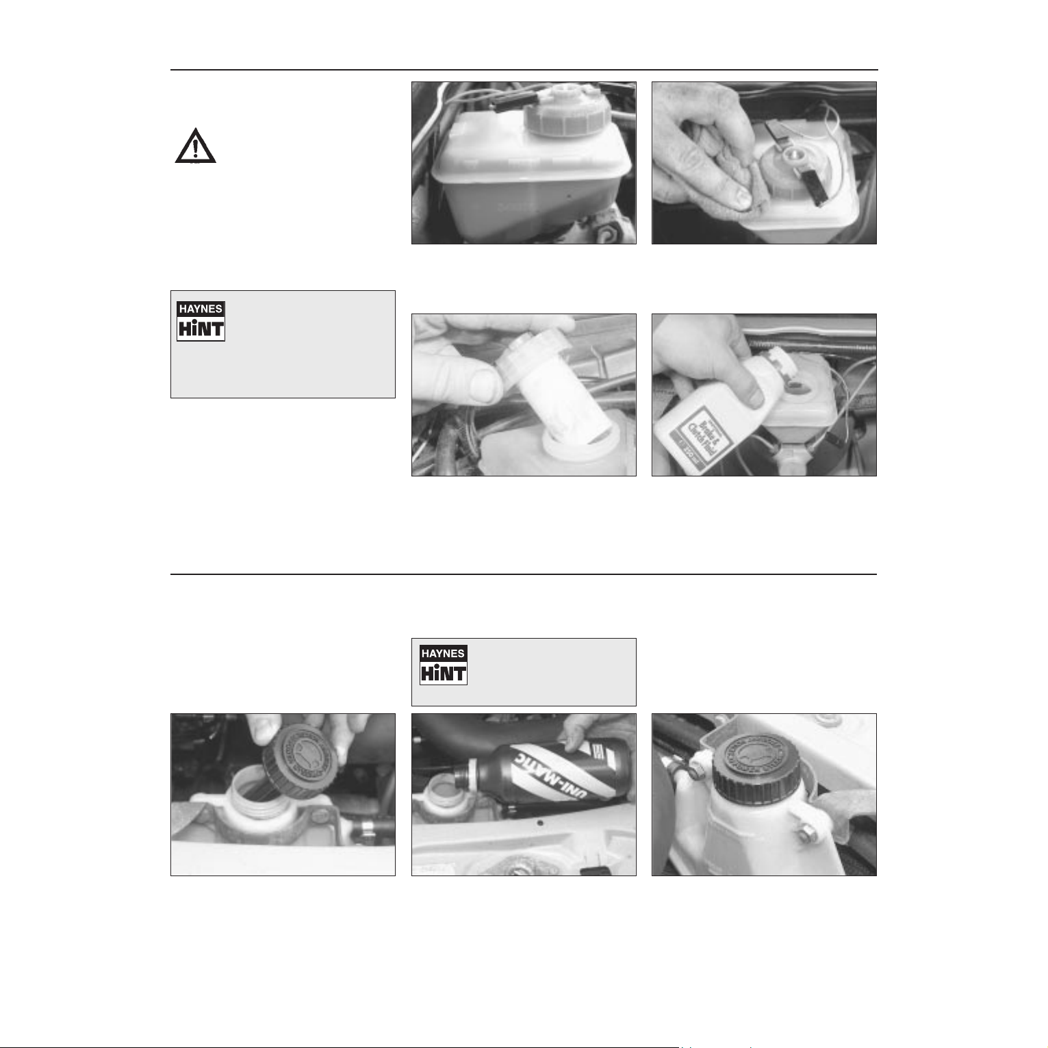
• Make sure that your car is
on level ground.
• The fluid level in the
reservoir will drop slightly as
the brake pads wear down, but the fluid
level must never be allowed to drop
below the “MIN” mark.
The “MAX” and “MIN” marks are
indicated on the front of the reservoir.
The fluid level must be kept between the
marks at all times.
1
If topping-up is necessary, first wipe
clean the area around the filler cap to
prevent dirt entering the hydraulic
system.
2
Unscrew the reservoir cap and carefully
lift it out of position. Inspect the reservoir,
if the fluid is dirty the hydraulic system
should be drained and refilled (see Chapter 1).
3
Carefully add fluid, taking care not to spill
it onto the surrounding components. Use
only the specified fluid; mixing different
types can cause damage to the system. After
topping-up to the correct level, securely refit
the cap and wipe off any spilt fluid.
4
Power steering fluid level
Before you start:
4 Park the vehicle on level ground.
4 Set the steering wheel straight-ahead.
4 The engine should be turned off.
Safety First!
l The need for frequent topping-up indicates
a leak, which should be investigated
immediately.
For the check to be
accurate, the steering must
not be turned once the
engine has been stopped.
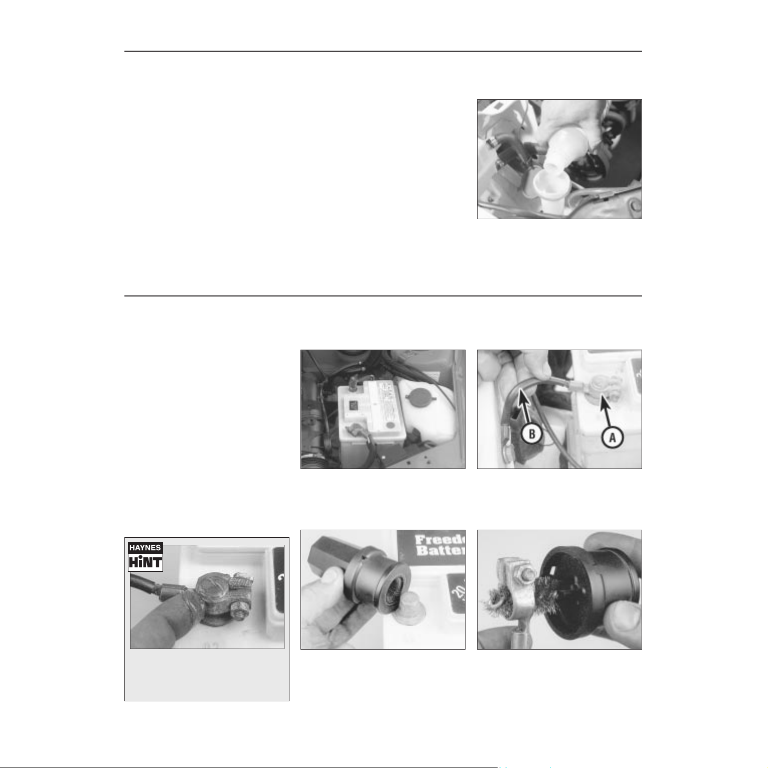
The reservoir is located in the front lefthand corner of the engine compartment,
next to the battery. Wipe clean the area
around the reservoir filler neck and unscrew
the filler cap/dipstick from the reservoir.
1
When the engine is cold, the fluid level
should be between the “MAX” mark and
the “MIN” mark on the reservoir or filler
cap dipstick. Top-up as necessary to maintain
the level between the two marks.
2
When topping-up, use the specified type
of fluid and do not overfill the reservoir.
When the level is correct, securely refit
the cap.
3
Weekly checks 0•13
Screenwash additives not only keep the
winscreen clean during foul weather, they also
prevent the washer system freezing in cold
weather - which is when you are likely to need it
most. Don’t top up using plain water as the
screenwash will become too diluted, and will
freeze during cold weather. On no account use
coolant antifreeze in the washer system this could discolour or damage paintwork.
The screenwasher fluid is also used to
clean the tailgate rear window, and on some
models, the headlights
The washer fluid reservoir filler is located at
the front left-hand side of the engine
compartment (or right-hand side on models
with headlight wash).
The washer reservoir itself is actually located
under the car on some models; release the
cap and observe the level in the reservoir by
looking down the filler neck.
Screen washer fluid level
When topping-up the reservoir, add a
screenwash additive in the quantities
recommended on the bottle.
1
Battery
Caution: Before carrying out any work on the
vehicle battery, read the precautions given in
"Safety first" at the start of this manual.
4 Make sure that the battery tray is in good
condition, and that the clamp is tight.
Corrosion on the tray, retaining clamp and the
battery itself can be removed with a solution
of water and baking soda. Thoroughly rinse all
cleaned areas with water. Any metal parts
damaged by corrosion should be covered
with a zinc-based primer, then painted.
4 Periodically (approximately every three
months), check the charge condition of the
battery as described in Chapter 5A.
4 If the battery is flat, and you need to jump
start your vehicle, see Roadside Repairs.
The battery is located on the left-hand
side of the engine compartment. The
exterior of the battery should be
inspected periodically for damage such as a
cracked case or cover.
1
Check the tightness of battery clamps (A)
to ensure good electrical connections.
You should not be able to move them.
Also check each cable (B) for cracks and
frayed conductors.
2
Battery corrosion can be kept to a
minimum by applying a layer of
petroleum jelly to the clamps and
terminals after they are reconnected.
If corrosion (white, fluffy deposits) is
evident, remove the cables from the
battery terminals, clean them with a small
wire brush, then refit them. Automotive stores
sell a tool for cleaning the battery post . . .
3
. . . as well as the battery cable clamps
4
0•14 Weekly checks
Tyre condition and pressure
It is very important that tyres are in good
condition, and at the correct pressure - having
a tyre failure at any speed is highly dangerous.
Tyre wear is influenced by driving style - harsh
braking and acceleration, or fast cornering,
will all produce more rapid tyre wear. As a
general rule, the front tyres wear out faster
than the rears. Interchanging the tyres from
front to rear ("rotating" the tyres) may result in
more even wear. However, if this is
completely effective, you may have the
expense of replacing all four tyres at once!
Remove any nails or stones embedded in the
tread before they penetrate the tyre to cause
deflation. If removal of a nail does reveal that
the tyre has been punctured, refit the nail so
that its point of penetration is marked. Then
immediately change the wheel, and have the
tyre repaired by a tyre dealer.
Regularly check the tyres for damage in the
form of cuts or bulges, especially in the
sidewalls. Periodically remove the wheels,
and clean any dirt or mud from the inside and
outside surfaces. Examine the wheel rims for
signs of rusting, corrosion or other damage.
Light alloy wheels are easily damaged by
"kerbing" whilst parking; steel wheels may
also become dented or buckled. A new wheel
is very often the only way to overcome severe
damage.
New tyres should be balanced when they are
fitted, but it may become necessary to rebalance them as they wear, or if the balance
weights fitted to the wheel rim should fall off.
Unbalanced tyres will wear more quickly, as
will the steering and suspension components.
Wheel imbalance is normally signified by
vibration, particularly at a certain speed
(typically around 50 mph). If this vibration is
felt only through the steering, then it is likely
that just the front wheels need balancing. If,
however, the vibration is felt through the
whole car, the rear wheels could be out of
balance. Wheel balancing should be carried
out by a tyre dealer or garage.
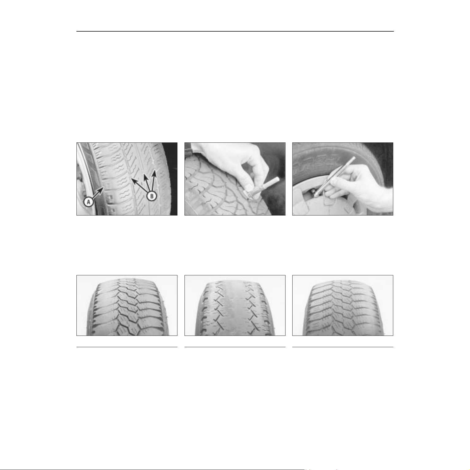
Tread Depth - visual check
The original tyres have tread wear safety
bands (B), which will appear when the tread
depth reaches approximately 1.6 mm. The
band positions are indicated by a triangular
mark on the tyre sidewall (A).
1
Tread Depth - manual check
Alternatively, tread wear can be
monitored with a simple, inexpensive device
known as a tread depth indicator gauge.
2
Tyre Pressure Check
Check the tyre pressures regularly with
the tyres cold. Do not adjust the tyre
pressures immediately after the vehicle has
been used, or an inaccurate setting will result.
3
Tyre tread wear patterns
Shoulder Wear
Underinflation (wear on both sides)
Under-inflation will cause overheating of the
tyre, because the tyre will flex too much, and
the tread will not sit correctly on the road
surface. This will cause a loss of grip and
excessive wear, not to mention the danger of
sudden tyre failure due to heat build-up.
Check and adjust pressures
Incorrect wheel camber (wear on one side)
Repair or renew suspension parts
Hard cornering
Reduce speed!
Centre Wear
Overinflation
Over-inflation will cause rapid wear of the
centre part of the tyre tread, coupled with
reduced grip, harsher ride, and the danger of
shock damage occurring in the tyre casing.
Check and adjust pressures
If you sometimes have to inflate your car’s
tyres to the higher pressures specified for
maximum load or sustained high speed, don’t
forget to reduce the pressures to normal
afterwards.
Uneven Wear
Front tyres may wear unevenly as a result of
wheel misalignment. Most tyre dealers and
garages can check and adjust the wheel
alignment (or "tracking") for a modest charge.
Incorrect camber or castor
Repair or renew suspension parts
Malfunctioning suspension
Repair or renew suspension parts
Unbalanced wheel
Balance tyres
Incorrect toe setting
Adjust front wheel alignment
Note: The feathered edge of the tread which
typifies toe wear is best checked by feel.
Weekly checks 0•15
Bulbs and fuses
4 Check all external lights and the horn.
Refer to the appropriate Sections of Chapter 12 for details if any of the circuits are
found to be inoperative.
4 Visually check all accessible wiring
connectors, harnesses and retaining clips for
security, and for signs of chafing or damage.
If you need to check your
brake lights and indicators
unaided, back up to a wall or
garage door and operate the
lights. The reflected light should show if
they are working properly.
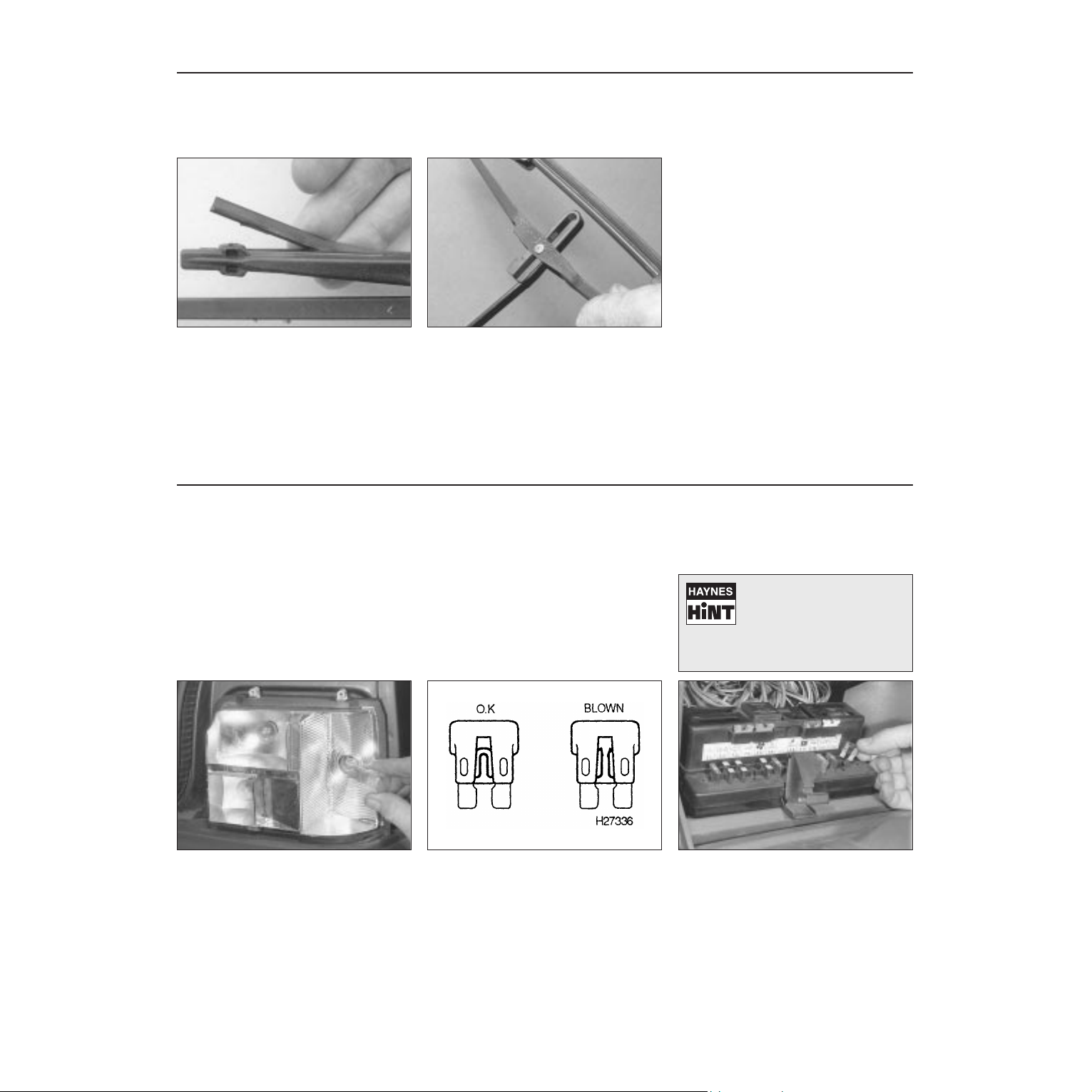
If a single indicator light, stop-light or
headlight has failed, it is likely that a bulb
has blown and will need to be replaced.
Refer to Chapter 12 for details. If both stoplights have failed, it is possible that the switch
has failed (see Chapter 12).
If more than one indicator light or tail light
has failed it is likely that either a fuse has
blown or that there is a fault in the circuit
(see Chapter 12). The fuses are located
behind a panel on the bottom of the driver’s
side lower facia panel.
2
To replace a blown fuse, simply pull it out
and fit a new fuse of the correct rating
(see Chapter 12). If the fuse blows again,
it is important that you find out why - a
complete checking procedure is given in
Chapter 12.
3
1
Wiper blades
Check the condition of the wiper blades;
if they are cracked or show any signs of
deterioration, or if the glass swept area is
smeared, renew them. Wiper blades should
be renewed annually.
1
To remove a windscreen wiper blade, pull
the arm fully away from the screen until it
locks. Swivel the blade through 90°,
press the locking tab with your fingers and
slide the blade out of the arm’s hooked end.
2
4 Don’t forget to check the tailgate wiper
blade as well. To remove the blade, depress
the retaining tab and slide the blade out of the
hooked end of the arm.
0•16 Lubricants, fluids and tyre pressures
Lubricants and fluids
Engine . . . . . . . . . . . . . . . . . . . . . . . Multigrade engine oil, viscosity SAE 10W/40, or 15W/40, to API SG/CD
(Duckhams QXR, QS or Hypergrade Plus)
Cooling system . . . . . . . . . . . . . . . . Ethylene glycol-based antifreeze (Duckhams Antifreeze and Summer
Coolant)
Manual transmission:
BH3 transmission . . . . . . . . . . . . Multigrade engine oil, viscosity SAE 10W/40 or 15W/40, to API SG/CD
(Duckhams QXR or Hypergrade Plus)
BE1, and BE3 transmissions:
Pre-August 1987 . . . . . . . . . . . Multigrade engine oil, viscosity SAE 10W/40 or 15W/40, to API SG/CD
(Duckhams QXR or Hypergrade Plus)
August 1987 onward . . . . . . . . Gear oil, viscosity SAE 75W/80 (Duckhams Hypoid PT 75W/80W Gear oil)
MA transmission . . . . . . . . . . . . . Gear oil, viscosity SAE 75W/80 (Duckhams Hypoid PT 75W/80W Gear oil)
Automatic transmission . . . . . . . . . Dexron type II automatic transmission fluid (Duckhams Uni-Matic)
Braking system . . . . . . . . . . . . . . . . Universal brake fluid to DOT 4 (Duckhams Universal Brake and Clutch Fluid)
Power steering . . . . . . . . . . . . . . . . Dexron type II automatic transmission fluid (Duckhams Uni-Matic)
Tyre pressures
Front Rear
135 SR 13 . . . . . . . . . . . . . . . . . . . . . . . . . . . . . . . . . . . 2.0 bars 2.1 bars
145 SR 13 (Hatchback models) . . . . . . . . . . . . . . . . . . 1.9 bars 2.1 bars
145 SR 13 (Van models):
Normal use . . . . . . . . . . . . . . . . . . . . . . . . . . . . . . . . . 1.9 bars 2.3 bars
Fully laden . . . . . . . . . . . . . . . . . . . . . . . . . . . . . . . . . 1.9 bars 2.6 bars
165/70 SR 13 (manual transmission models) . . . . . . . . 1.7 bars 1.9 bars
165/70 SR 13 (automatic transmission models) . . . . . . 2.0 bars 2.1 bars
185/60 HR 14 (except CTI models) . . . . . . . . . . . . . . . . 2.0 bars 2.0 bars
185/60 HR 14 (CTI models) . . . . . . . . . . . . . . . . . . . . . . 2.0 bars 2.1 bars
185/55 VR 15 . . . . . . . . . . . . . . . . . . . . . . . . . . . . . . . . 2.0 bars 2.0 bars
Note: Refer to the tyre pressure data sticker for the correct tyre pressures for your particular vehicle. Pressures apply only to original-equipment
tyres, and may vary if other makes or type is fitted; check with the tyre manufacturer or supplier for correct pressures if necessary.
Oils perform vital tasks in all engines. The
higher the engine’s performance, the greater
the demand on lubricants to minimise wear as
well as optimise power and economy.
Duckhams tailors lubricants to the highest
technical standards, meeting and exceeding
the demands of all modern engines.
HOW ENGINE OIL WORKS
• Beating friction
Without oil, the surfaces inside your engine
which rub together will heat, fuse and quickly
cause engine seizure. Oil, and its special
additives, forms a molecular barrier between
moving parts, to stop wear and minimise heat
build-up.
• Cooling hot spots
Oil cools parts that the engine’s water-based
coolant cannot reach, bathing the combustion
chamber and pistons, where temperatures
may exceed 1000°C. The oil assists in
transferring the heat to the engine cooling
system. Heat in the oil is also lost by air flow
over the sump, and via any auxiliary oil cooler.
• Cleaning the inner engine
Oil washes away combustion by-products
(mainly carbon) on pistons and cylinders,
transporting them to the oil filter, and holding
the smallest particles in suspension until they
are flushed out by an oil change. Duckhams
oils undergo extensive tests in the laboratory,
and on the road.
Engine oil types
Mineral oils are the “traditional” oils,
generally suited to older engines and cars not
used in harsh conditions. Duckhams
Hypergrade Plus and Hypergrade are well
suited for use in most popular family cars.
Diesel oils such as Duckhams Diesel are
specially formulated for Diesel engines,
including turbocharged models and 4x4s.
Synthetic oils are the state-of-the-art in
lubricants, offering ultimate protection, but at
a fairly high price. One such is Duckhams QS,
for use in ultra-high performance engines.
Semi-synthetic oils offer high performance
engine protection, but at less cost than full
synthetic oils. Duckhams QXR is an ideal choice
for hot hatches and hard-driven cars.
For help with technical
queries on lubricants,
call Duckhams Oils
on 0181 290 8207
Choosing your engine oil
Note: It is
antisocial and
illegal to dump oil
down the drain.
To find the
location of your
local oil recycling
bank, call this
number free.
1
Chapter 1
Routine maintenance and servicing
Air cleaner filter element renewal . . . . . . . . . . . . . . . . . . . . . . . . . . . . 26
Air conditioning system check . . . . . . . . . . . . . . . . . . . . . . . . . . . . . . 20
Automatic transmission fluid level check . . . . . . . . . . . . . . . . . . . . . 5
Automatic transmission fluid renewal . . . . . . . . . . . . . . . . . . . . . . . . 23
Auxiliary drivebelt check and renewal . . . . . . . . . . . . . . . . . . . . . . . . 9
Bodywork, paint and exterior trim check . . . . . . . . . . . . . . . . . . . . . . 18
Brake fluid renewal . . . . . . . . . . . . . . . . . . . . . . . . . . . . . . . . . . . . . . 34
Clutch pedal stroke adjustment . . . . . . . . . . . . . . . . . . . . . . . . . . . . . 10
Coolant renewal . . . . . . . . . . . . . . . . . . . . . . . . . . . . . . . . . . . . . . . . . 33
Driveshaft bellows check . . . . . . . . . . . . . . . . . . . . . . . . . . . . . . . . . . 24
Engine oil and filter renewal . . . . . . . . . . . . . . . . . . . . . . . . . . . . . . . . 3
Exhaust system check . . . . . . . . . . . . . . . . . . . . . . . . . . . . . . . . . . . . 17
Emissions control systems check . . . . . . . . . . . . . . . . . . . . . . . . . . . 29
Front brake pad check . . . . . . . . . . . . . . . . . . . . . . . . . . . . . . . . . . . . 4
Fuel filter renewal - fuel injection models . . . . . . . . . . . . . . . . . . . . . 32
Handbrake check and adjustment . . . . . . . . . . . . . . . . . . . . . . . . . . . 15
Headlight beam alignment check . . . . . . . . . . . . . . . . . . . . . . . . . . . 19
Idle speed and mixture check and adjustment . . . . . . . . . . . . . . . . . 28
Ignition system check . . . . . . . . . . . . . . . . . . . . . . . . . . . . . . . . . . . . 27
Intensive maintenance . . . . . . . . . . . . . . . . . . . . . . . . . . . . . . . . . . . . 2
Introduction . . . . . . . . . . . . . . . . . . . . . . . . . . . . . . . . . . . . . . . . . . . . 1
Lock and hinge check and lubrication . . . . . . . . . . . . . . . . . . . . . . . . 12
Manual transmission oil level check . . . . . . . . . . . . . . . . . . . . . . . . . 21
Manual transmission oil renewal . . . . . . . . . . . . . . . . . . . . . . . . . . . . 22
Rear brake pad condition check - models with rear disc brakes . . . 14
Rear brake shoe check - models with rear drum brakes . . . . . . . . . 13
Road test . . . . . . . . . . . . . . . . . . . . . . . . . . . . . . . . . . . . . . . . . . . . . . 30
Seat belt check . . . . . . . . . . . . . . . . . . . . . . . . . . . . . . . . . . . . . . . . . 11
Spark plug renewal . . . . . . . . . . . . . . . . . . . . . . . . . . . . . . . . . . . . . . 7
Steering and suspension check . . . . . . . . . . . . . . . . . . . . . . . . . . . . 25
Throttle and choke cable lubrication and adjustment . . . . . . . . . . . . 8
Timing belt renewal . . . . . . . . . . . . . . . . . . . . . . . . . . . . . . . . . . . . . . 31
Underbody and fuel/brake line check . . . . . . . . . . . . . . . . . . . . . . . . 16
Underbonnet check for fluid leaks and hose condition . . . . . . . . . . . 6
1•1
Contents
Easy, suitable for
novice with little
experience
Fairly easy, suitable
for beginner with
some experience
Fairly difficult,
suitable for competent
DIY mechanic
Difficult, suitable for
experienced DIY
mechanic
Very difficult,
suitable for expert DIY
or professional
Degrees of difficulty
5
4
3
2
1

1•2 Servicing Specifications
Lubricants and fluids . . . . . . . . . . . . . . . . . . . . . . . . . . . . . . . . . . Refer to end of “Weekly checks”
Capacities
Engine oil
XV and XW series engines (including filter) . . . . . . . . . . . . . . . . . . . . 4.5 litres
XY and XU series engines (including filter) . . . . . . . . . . . . . . . . . . . . 5.0 litres
TU series engines (including filter) . . . . . . . . . . . . . . . . . . . . . . . . . . . 3.5 litres
Cooling system
XV8, XW7, TU9 and TU3 series engines . . . . . . . . . . . . . . . . . . . . . . . 5.8 litres
XY7 and XY8 engines . . . . . . . . . . . . . . . . . . . . . . . . . . . . . . . . . . . . . 6.0 litres
XU engines (except automatic transmission models) . . . . . . . . . . . . . 6.6 litres
XU engines (automatic transmission models) . . . . . . . . . . . . . . . . . . . 6.7 litres
TU1 series engine (except Van models) . . . . . . . . . . . . . . . . . . . . . . . 7.0 litres
TU1 series engine (Van models) . . . . . . . . . . . . . . . . . . . . . . . . . . . . . 5.8 litres
Manual transmission . . . . . . . . . . . . . . . . . . . . . . . . . . . . . . . . . . . . . . 2.0 litres
Automatic transmission
From dry . . . . . . . . . . . . . . . . . . . . . . . . . . . . . . . . . . . . . . . . . . . . . . . 6.2 litres
Drain and refill . . . . . . . . . . . . . . . . . . . . . . . . . . . . . . . . . . . . . . . . . . . 2.4 litres
Fuel tank . . . . . . . . . . . . . . . . . . . . . . . . . . . . . . . . . . . . . . . . . . . . . . . . 50 litres
Engine
Oil filter:
XV, XW and XY series engines . . . . . . . . . . . . . . . . . . . . . . . . . . . . . . Champion C204
XU and TU series engines . . . . . . . . . . . . . . . . . . . . . . . . . . . . . . . . . . Champion F104
Cooling system
Antifreeze mixture:
Protection down to - 15ºC (5ºF) . . . . . . . . . . . . . . . . . . . . . . . . . . . . . 27% antifreeze
Protection down to - 35ºC (- 31ºF) . . . . . . . . . . . . . . . . . . . . . . . . . . . 50% antifreeze
Note: Refer to Chapter 3 for further details.
Fuel system
Air cleaner filter element:
Pre-1988 carburettor engines . . . . . . . . . . . . . . . . . . . . . . . . . . . . . . . Champion W138
1988 onward carburettor engines . . . . . . . . . . . . . . . . . . . . . . . . . . . . Champion U401
Fuel injection engines . . . . . . . . . . . . . . . . . . . . . . . . . . . . . . . . . . . . . Champion W175
Fuel filter . . . . . . . . . . . . . . . . . . . . . . . . . . . . . . . . . . . . . . . . . . . . . . . . . Champion L205
Idle speed and mixture CO content . . . . . . . . . . . . . . . . . . . . . . . . . . . . Refer to Chapter 4A, 4B and 4C Specifications
Ignition system
Spark plugs:
XV8, XW7 and XY7 engines . . . . . . . . . . . . . . . . . . . . . . . . . . . . . . . . Champion RS9YCC or S281YC*
XY8 and XU5J engines . . . . . . . . . . . . . . . . . . . . . . . . . . . . . . . . . . . . Champion S7YCC or S279YC*
XU51C engines (up to 1988) . . . . . . . . . . . . . . . . . . . . . . . . . . . . . . . . Champion S9YCC or S281YC*
XU51C engines (from 1988) . . . . . . . . . . . . . . . . . . . . . . . . . . . . . . . . Champion RC9YCC or C9YCX*
XU5JA engines (up to 1988) . . . . . . . . . . . . . . . . . . . . . . . . . . . . . . . . Champion S7YCC or S279YC*
XU5JA (from 1988), XU5JA/K, XU9JA, XU9JA/K, XU9JA/Z and
XU9JA/L engines . . . . . . . . . . . . . . . . . . . . . . . . . . . . . . . . . . . . . . . . Champion RC7YCC or C7YCX*
TU9 series, TU1 series, TU3 and TU3A engines . . . . . . . . . . . . . . . . . Champion RC9YCC or C9YCX*
TU3S engines . . . . . . . . . . . . . . . . . . . . . . . . . . . . . . . . . . . . . . . . . . . Champion RC7YCC or C7YCX*
*Peugeot recommendation
Spark plug electrode gap** . . . . . . . . . . . . . . . . . . . . . . . . . . . . . . . . . . . 0.7 to 0.8 mm
**The spark plug electrode gap quoted is that recommended by Champion for their specified plugs listed above. If spark plugs of any other type
are to be fitted, refer to their manufacturer’s recommendations.
Brakes
Front brake pad minimum lining thickness . . . . . . . . . . . . . . . . . . . . . . . 2.0 mm
Rear brake shoe minimum lining thickness . . . . . . . . . . . . . . . . . . . . . . 1.0 mm
Rear brake pad minimum lining thickness . . . . . . . . . . . . . . . . . . . . . . . 2.0 mm
Tyre pressures . . . . . . . . . . . . . . . . . . . . . . . . . . . . . . . . . . . . . . . . See “Weekly checks”
Torque wrench settings Nm lbf ft
Spark plugs . . . . . . . . . . . . . . . . . . . . . . . . . . . . . . . . . . . . . . . . . . . . . . . 17 13
Manual transmission drain/filler plugs
BE1 and BE3 transmissions:
Main gearbox drain plug . . . . . . . . . . . . . . . . . . . . . . . . . . . . . . . . . 10 7
Final drive drain plug . . . . . . . . . . . . . . . . . . . . . . . . . . . . . . . . . . . . 30 22
MA transmission . . . . . . . . . . . . . . . . . . . . . . . . . . . . . . . . . . . . . . . . . 25 19

Maintenance schedule 1•3
1
Every 250 miles (400 km) or weekly
mm
˛
Refer to “Weekly checks”.
Every 36 000 miles (58 000 km) or
3 years - whichever comes sooner
In addition to all the items listed above, carry out the following:
mm
˛
Renew the timing belt (Section 31).
Note: Although the normal interval for timing belt renewal is 72 000
miles (120 000 km), It is strongly recommended that the timing belt
renewal interval is halved to 36 000 miles (60 000 km) on vehicles
which are subjected to intensive use, ie. mainly short journeys or a lot
of stop-start driving. The actual belt renewal interval is therefore very
much up to the individual owner, but bear in mind that severe engine
damage will result if the belt breaks.
Every 6000 miles (9000 km) or
6 months - whichever comes sooner
In addition to all the items listed above, carry out the following:
mm Renew the engine oil and filter (Section 3)*.
mm
˛
Check the condition of the front brake pads, and renew if
necessary (Section 4).
mm
˛
Check the automatic transmission fluid level and top-up if
necessary (Section 5).
Note: Renewal of the engine oil filter at this service interval is only
necessary on models fitted with the XU9J1/L engine and automatic
transmission. On all other models, oil filter renewal is recommended
at every second oil change (ie 12 000 miles/12 months).
Every 48 000 miles (80 000 km) or
4 years - whichever comes sooner
mm
˛
Renew the fuel filter - fuel injection models (Section 32).
Every 12 000 miles (18 000 km) or
12 months - whichever comes sooner
In addition to all the items listed above, carry out the following:
mm
˛
Check all underbonnet components and hoses for fluid leaks
(Section 6).
mm
˛
Renew the spark plugs (Section 7).
mm
˛
Check, adjust and lubricate the throttle and choke cables
(Section 8).
mm
˛
Check the condition of the auxiliary drivebelt, and renew if
necessary (Section 9).
mm
˛
Check the clutch pedal stroke adjustment (Section 10).
mm
˛
Check the condition of the seat belts (Section 11).
mm
˛
Lubricate the locks and hinges (Section 12).
mm
˛
Check the condition of the rear brake shoes and renew if
necessary - rear drum brake models (Section 13).
mm
˛
Check the condition of the rear brake pads and renew if
necessary - rear disc brake models (Section 14).
mm
˛
Check the operation of the handbrake (Section 15).
mm
˛
Inspect the underbody and the brake hydraulic pipes and hoses
(Section 16).
mm
˛
Check the condition of the fuel lines (Section 16).
mm
˛
Check the condition and security of the exhaust system (Section 17).
mm
˛
Check the condition of the exterior trim and paintwork (Section 18).
mm
˛
Check the headlight beam alignment (Section 19).
mm
˛
Check the operation of the air conditioning system (Section 20).
Every 72 000 miles (120 000 km)
In addition to all the items listed above, carry out the following:
mm
˛
Renew the timing belt (Section 31).
Note: This is the interval recommended by Peugeot, but we
recommend that the belt is changed more frequently, at 36 000 miles
(60 000 km) - see above
Every 24 000 miles (36 000 km) or
2 years - whichever comes sooner
In addition to all the items listed above, carry out the following:
mm
˛
Check the manual transmission oil level, and top-up if necessary
(Section 21).
mm
˛
Renew the manual transmission oil (pre-1988 BE1 transmissions
only) (Section 22).
mm
˛
Renew the automatic transmission fluid (Section 23).
mm
˛
Check the condition of the driveshaft bellows (Section 24).
mm
˛
Check the steering and suspension components for condition
and security (Section 25).
mm
˛
Renew the air cleaner filter element (Section 26).
mm
˛
Check the ignition system (Section 27).
mm
˛
Check the idle speed and mixture adjustment (Section 28).
mm
˛
Check the condition of the emissions control system hoses and
components (Section 29).
mm
˛
Carry out a road test (Section 30).
Every 2 years (regardless of mileage)
mm
˛
Renew the coolant (Section 33).
mm
˛
Renew the brake fluid (Section 34).
The maintenance intervals in this manual
are provided with the assumption that you,
not the dealer, will be carrying out the work.
These are the average maintenance intervals
recommended for vehicles driven daily under
normal conditions. Obviously some variation
of these intervals may be expected depending
on territory of use, and conditions
encountered. If you wish to keep your vehicle
in peak condition at all times, you may wish to
perform some of these procedures more
often. We encourage frequent maintenance
because it enhances the efficiency,
performance and resale value of your vehicle.
If the vehicle is driven in dusty areas, used
to tow a trailer, driven frequently at slow
speeds (idling in traffic) or on short journeys,
more frequent maintenance intervals are
recommended.
1•4 Maintenance - component location
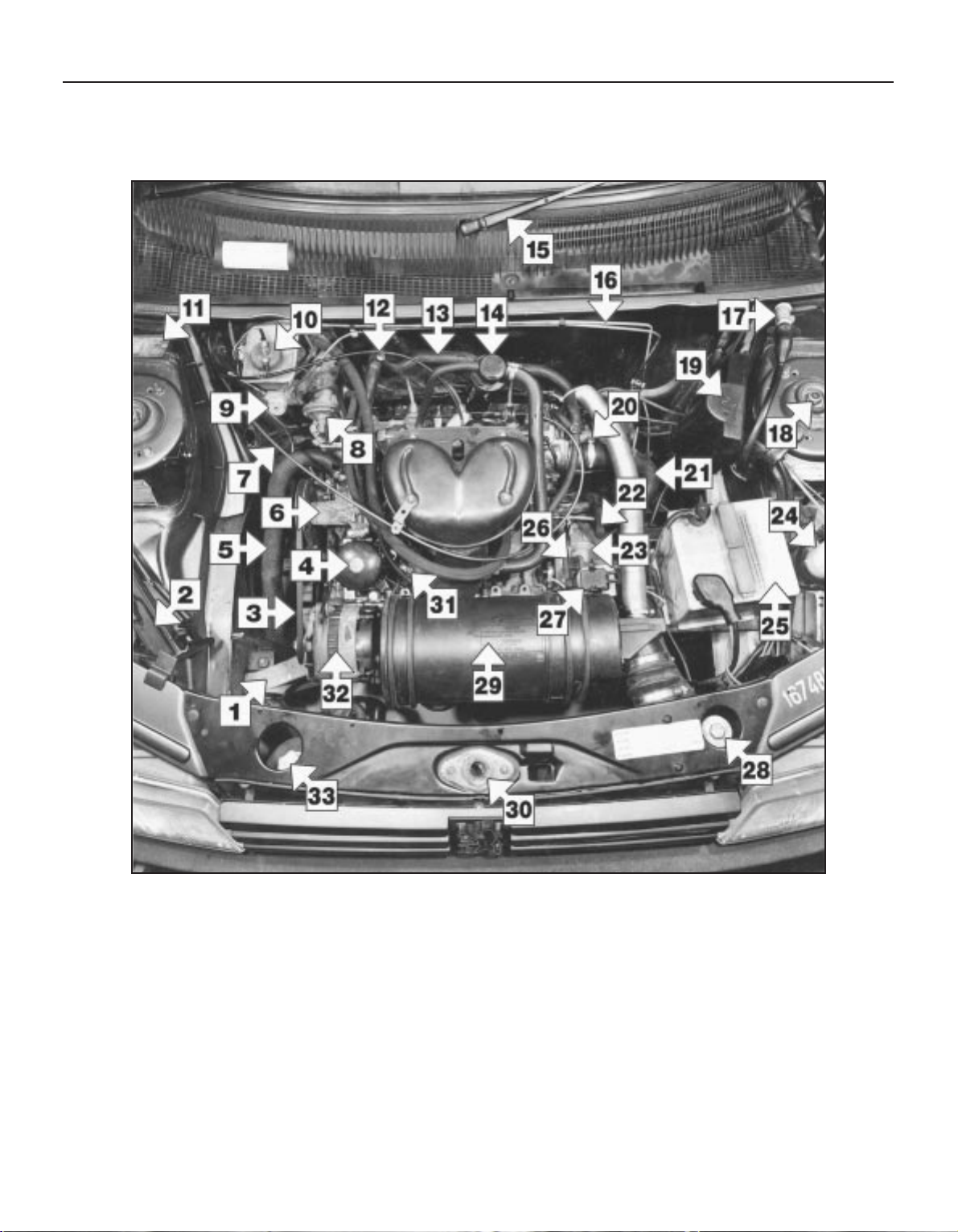
Underbonnet view of a 1360 cc GT model (XY8 series engine)
1 Right-hand front engine mounting
2 Jack
3 Drivebelt
4 Oil filter
5 Bottom hose
6 Water pump
7 Throttle cable
8 Fuel pump
9 Brake master cylinder
10 Brake fluid reservoir filler cap
11 Vehicle identification plate
12 Choke cable
13 Heater hose
14 Oil filler cap/crankcase ventilation filter
15 Windscreen wiper arm
16 Hydraulic brake lines
17 Cooling fan motor resistor
18 Front suspension shock absorber top
mounting nut
19 Ignition coil cover
20 Distributor
21 Bottom hose
22 Clutch release fork
23 Clutch housing
24 Washer reservoir
25 Battery
26 Ignition timing aperture
27 Diagnostic socket
28 Radiator filler cap
29 Air cleaner
30 Bonnet lock
31 Oil pressure switch
32 Alternator
33 Cooling system expansion
bottle
Maintenance - component location 1•5
1
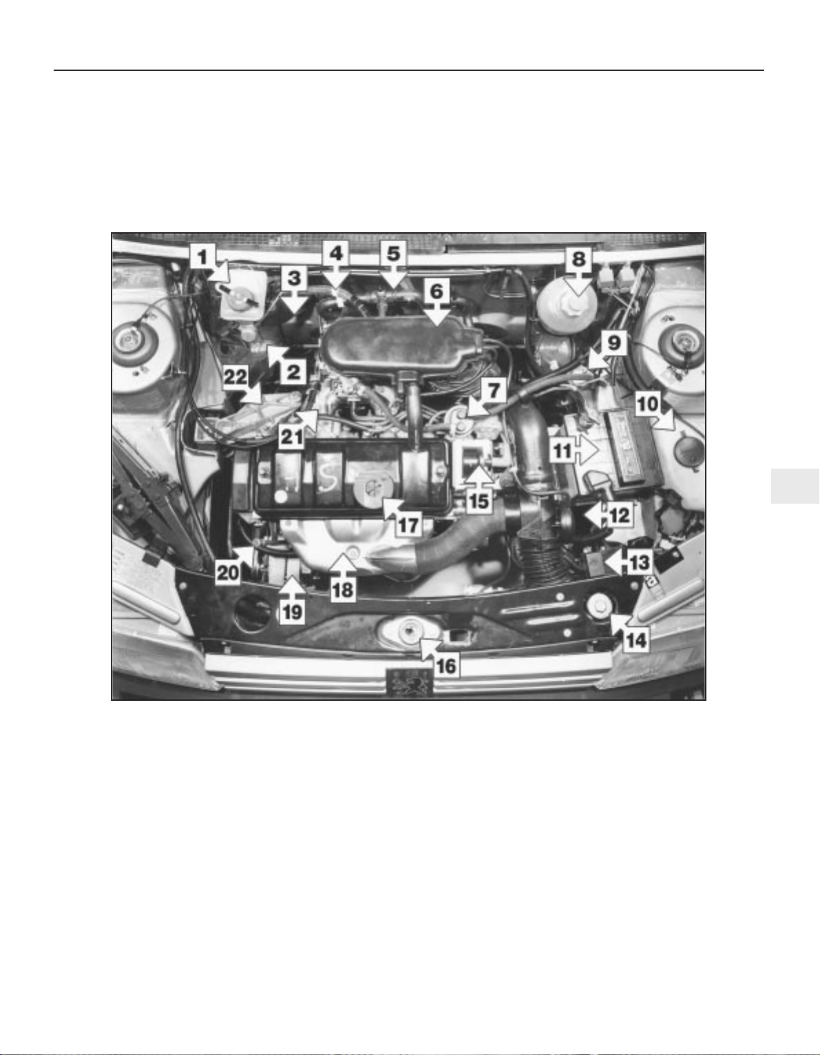
Underbonnet view of a 1360 cc XS model (TU series engine)
1 Brake fluid reservoir filler cap
2 Brake master cylinder
3 Brake vacuum servo unit
4 Servo vacuum hose
5 Cooling system bleed screw
6 Air cleaner cover
7 Fuel pump
8 Cooling system expansion bottle
9 Fuel filter
10 Washer fluid reservoir
11 Battery
12 Air temperature control unit
13 Auxiliary fusebox
14 Radiator filler cap
15 Ignition coil
16 Bonnet lock
17 Engine oil filler cap
18 Exhaust manifold hot air shroud
19 Alternator
20 Engine oil level dipstick
21 Inlet manifold
22 Right-hand engine mounting
1•6 Maintenance - component location
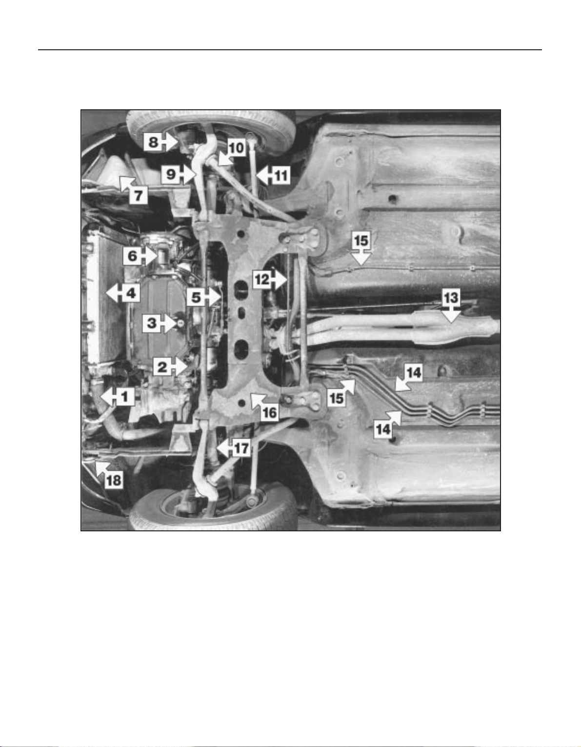
Front underside view of a 1360 cc GT model
1 Bottom hose
2 Reverse lamp switch
3 Engine/transmission oil drain plug
4 Radiator
5 Gear linkage
6 Clutch housing and transfer gear
assembly
7 Washer reservoir
8 Disc caliper
9 Lower suspension arm
10 Anti-roll bar
11 Track rod
12 Guide bar
13 Exhaust front pipe
14 Fuel feed and return pipes
15 Hydraulic brake lines
16 Subframe
17 Driveshaft
18 Front towing eye
Maintenance - component location 1•7
1
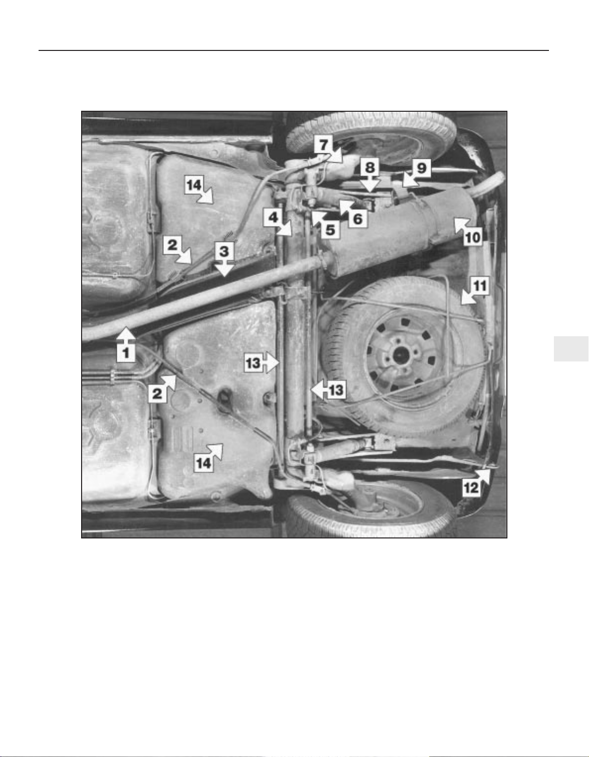
Rear underside view of a 1360 cc GT model
1 Exhaust front pipe
2 Handbrake cables
3 Heatshield
4 Rear suspension cross-tube
5 Brake hydraulic flexible hose
6 Rear shock absorber
7 Trailing arm
8 Side-member
9 Exhaust rubber mounting
10 Exhaust rear silencer
11 Spare wheel
12 Rear towing eye
13 Torsion bars
14 Fuel tank
1 Introduction
This Chapter is designed to help the home
mechanic maintain his/her vehicle for safety,
economy, long life and peak performance.
This Chapter contains a master
maintenance schedule, followed by Sections
dealing specifically with each task in the
schedule. Visual checks, adjustments,
component renewal and other helpful items
are included. Refer to the accompanying
illustrations of the engine compartment and
the underside of the vehicle for the locations
of the various components.
Servicing your vehicle in accordance with
the mileage/time maintenance schedule and
the following Sections will provide a planned
maintenance programme, which should result
in a long and reliable service life. This is a
comprehensive plan, so maintaining some
items but not others at the specified service
intervals will not produce the same results.
As you service your vehicle, you will
discover that many of the procedures can and should - be grouped together, because of
the particular procedure being performed, or
because of the close proximity of two
otherwise-unrelated components to one
another. For example, if the vehicle is raised
for any reason, the exhaust should be
inspected at the same time as the suspension
and steering components.
The first step of this maintenance
programme is to prepare yourself before the
actual work begins. Read through all the
Sections relevant to the work to be carried
out, then make a list and gather together all
the parts and tools required. If a problem is
encountered, seek advice from a parts
specialist or a dealer service department.
2 Intensive maintenance
1 If, from the time the vehicle is new, the
routine maintenance schedule is followed
closely, and frequent checks are made of fluid
levels and high-wear items, as suggested
throughout this manual, the engine will be
kept in relatively good running condition, and
the need for additional work will be minimised.
2 It is possible that there will be some times
when the engine is running poorly due to the
lack of regular maintenance. This is even more
likely if a used vehicle, which has not received
regular and frequent maintenance checks, is
purchased. In such cases, additional work
may need to be carried out, outside of the
regular maintenance intervals.
3 If engine wear is suspected, a compression
test (refer to Chapter 2A, B or C) will provide
valuable information regarding the overall
performance of the main internal components.
Such a test can be used as a basis to decide
on the extent of the work to be carried out. If,
for example, a compression test indicates
serious internal engine wear, conventional
maintenance as described in this Chapter will
not greatly improve the performance of the
engine, and may prove a waste of time and
money, unless extensive overhaul work
(Chapter 2D) is carried out first.
4 The following series of operations are those
often required to improve the performance of
a generally poor-running engine:
Primary operations
a) Clean, inspect and test the battery (See
“Weekly checks”).
b) Check all the engine-related fluids (See
“Weekly checks”).
c) Check the condition of the auxiliary
drivebelt (Section 9).
d) Inspect the distributor cap, rotor arm and
HT leads (Section 27).
e) Renew the spark plugs (Section 7).
f) Check the condition of the air cleaner
filter element and renew if necessary
(Section 26).
g) Renew the fuel filter - fuel injection
models (Section 32).
h) Check the condition of all hoses, and
check for fluid leaks (Section 6).
5 If the above operations do not prove fully
effective, carry out the following operations:
Secondary operations
All the items listed under “Primary
operations”, plus the following:
a) Check the charging system (Chapter 5A).
b) Check the ignition system (Chapter 5B).
c) Check the fuel system (Chapter 4A, B and
C).
d) Renew the distributor cap and rotor arm
(Section 27).
e) Renew the ignition HT leads (Section 27).
3 Engine oil and filter renewal
1
Note: A suitable square-section wrench may
be required to undo the sump drain plug on
some models. These wrenches can be
obtained from most motor factors or your
Peugeot dealer.
1 Frequent oil changes are the best
preventive maintenance the home mechanic
can give the engine, because ageing oil
becomes diluted and contaminated, which
leads to premature engine wear.
2 Make sure that you have all the necessary
tools before you begin this procedure. You
should also have plenty of rags or
newspapers handy, for mopping up any spills.
The oil should preferably be changed when
the engine is still fully warmed-up to normal
operating temperature, just after a run; warm
oil and sludge will flow out more easily. Take
care, however, not to touch the exhaust or
any other hot parts of the engine when
working under the vehicle. To avoid any
possibility of scalding, and to protect yourself
from possible skin irritants and other harmful
contaminants in used engine oils, it is
advisable to wear gloves when carrying out
this work. Access to the underside of the
vehicle is greatly improved if the vehicle can
be lifted on a hoist, driven onto ramps, or
supported by axle stands. (see “Jacking and
vehicle support”). Whichever method is
chosen, make sure that the vehicle remains
level, or if it is at an angle, that the drain point
is at the lowest point.
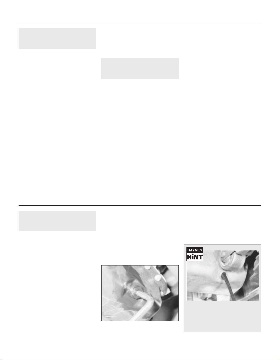
3 Position the draining container under the
drain plug, and unscrew the plug. On some
models, a square-section wrench may be
needed to slacken the plug (see illustration).
If possible, try to keep the plug pressed into
the sump while unscrewing it by hand the last
couple of turns (see Haynes Hint).
1•8 Maintenance procedures
3.3 Slackening the sump drain plug with a
square section wrench
Every 6000 miles or 6 months
Keep the drain plug pressed into the
sump while unscrewing it by hand the
last couple of turns. As the plug releases,
move it away sharply so that the stream
of oil issuing from the sump runs into the
container, not up your sleeve!
4 Allow the oil to drain into the container, and
check the condition of the plug’s sealing
washer; renew it if worn or damaged.
5 Allow some time for the old oil to drain,
noting that it may be necessary to reposition
the container as the oil flow slows to a trickle;
when the oil has completely drained, wipe
clean the drain plug and its threads in the
sump and refit the plug, tightening it securely.
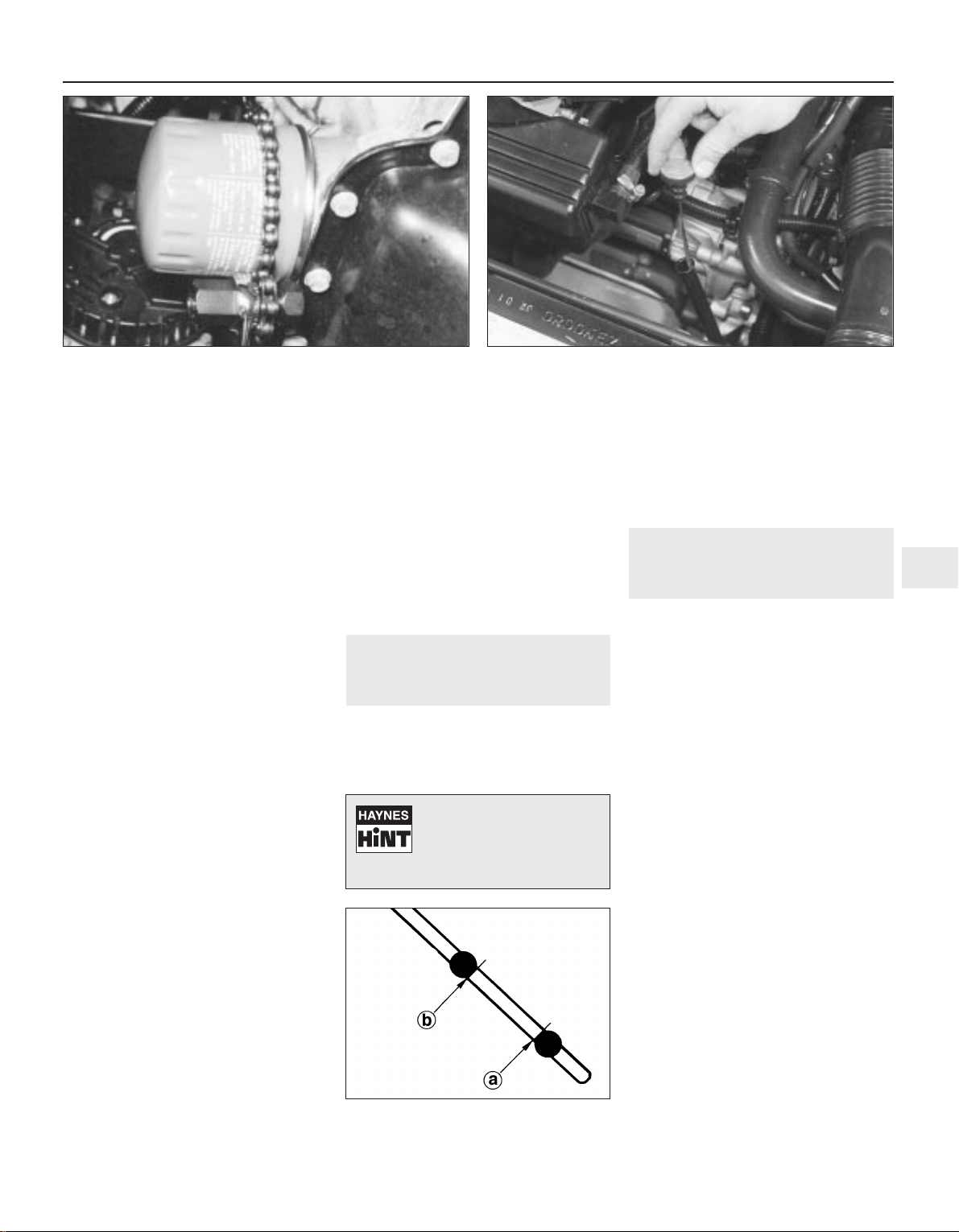
6 If the filter is also to be renewed, move the
container into position under the oil filter,
which is located on the front side of the
cylinder block. On XV, XW and XY series
engines, place some rag around the filter
otherwise the oil that runs out as the filter is
unscrewed will make a mess all over the front
of the engine.
7 Using an oil filter removal tool if necessary,
slacken the filter initially, then unscrew it by
hand the rest of the way (see illustration).
Empty the oil in the old filter into the
container.
8 Use a clean rag to remove all oil, dirt and
sludge from the filter sealing area on the
engine. Check the old filter to make sure that
the rubber sealing ring hasn’t stuck to the
engine. If it has, carefully remove it.
9 Apply a light coating of clean engine oil to
the sealing ring on the new filter, then screw it
into position on the engine. Tighten the filter
firmly by hand only - do not use any tools.
10 Remove the old oil and all tools from
under the car, then lower the car to the
ground (if applicable).
11 Remove the dipstick, then unscrew the oil
filler cap from the rocker/cylinder head cover
or oil filler/breather neck (as applicable). Fill
the engine, using the correct grade and type
of oil (see “Lubricants and fluids, and
capacities”). An oil can spout or funnel may
help to reduce spillage. Pour in half the
specified quantity of oil first, then wait a few
minutes for the oil to fall to the sump.
Continue adding oil a small quantity at a time
until the level is up to the lower mark on the
dipstick. Adding approximately 1.5 litres will
bring the level up to the upper mark on the
dipstick. Refit the filler cap.
12 Start the engine and run it for a few
minutes; check for leaks around the oil filter
seal and the sump drain plug. Note that there
may be a delay of a few seconds before the oil
pressure warning light goes out when the
engine is first started, as the oil circulates
through the engine oil galleries and the new oil
filter (if fitted) before the pressure builds up.
13 Switch off the engine, and wait a few
minutes for the oil to settle in the sump once
more. With the new oil circulated and the filter
completely full, recheck the level on the
dipstick, and add more oil as necessary.
14 Dispose of the used engine oil safely, with
reference to “General repair procedures” in
the preliminary Sections of this manual.
4 Front brake pad check
1
1 Jack up the front of the vehicle, and
support it on axle stands (see “Jacking and
vehicle support”).
2 For better access to the brake calipers,
remove the roadwheels.
3 If any of the pads friction material is worn to
the specified thickness or less, all four pads
must be renewed as a set.
4 For a comprehensive check, the brake pads
should be removed and cleaned. The
operation of the caliper can then also be
checked, and the condition of the brake disc
itself can be fully examined on both sides.
Refer to Chapter 9 for further information.
5 Automatic transmission fluid
level check
1
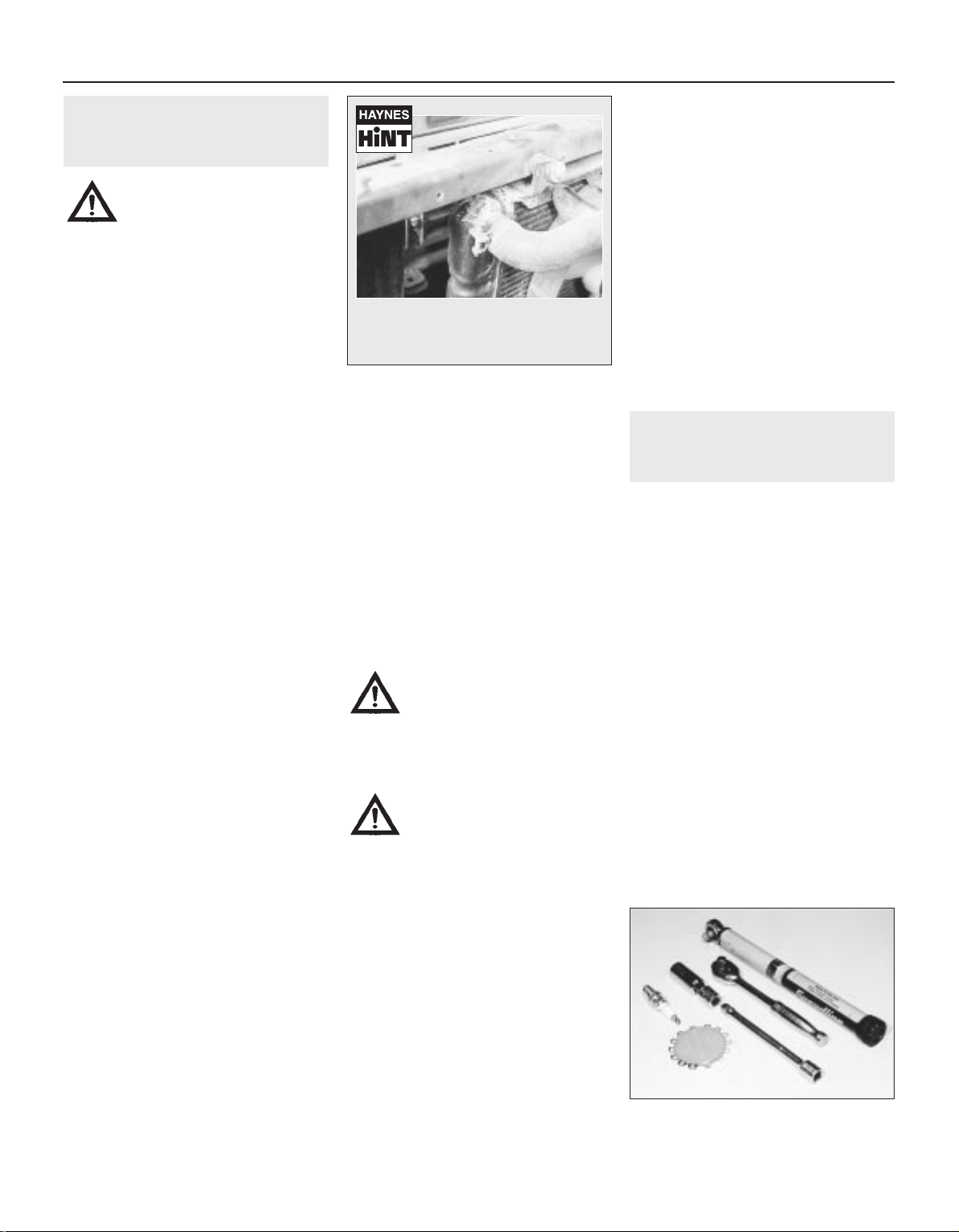
1 Take the vehicle on a short journey, to
warm the transmission up to normal operating
temperature, then park the vehicle on level
ground. The fluid level is checked using the
dipstick located at the front of the engine
compartment, directly in front of the engine
(see illustration). The dipstick top is brightlycoloured for easy identification.
2 With the engine idling and the selector lever
in the “P” (Park) position, withdraw the
dipstick from the tube, and wipe all the fluid
from its end with a clean rag or paper towel.
Insert the clean dipstick back into the tube as
far as it will go, then withdraw it once more.
Note the fluid level on the end of the dipstick;
it should be between the upper and lower
marks (see illustration).
3 If topping-up is necessary, add the required
quantity of the specified fluid to the transmission
via the dipstick tube. Use a funnel with a finemesh gauze, to avoid spillage, and to ensure
that no foreign matter enters the transmission.
Note: Never overfill the transmission so that the
fluid level is above the upper mark.
4 After topping-up, take the vehicle on a short
run to distribute the fresh fluid, then recheck
the level again, topping-up if necessary.
5 Always maintain the level between the two
dipstick marks. If the level is allowed to fall
below the lower mark, fluid starvation may
result, which could lead to severe
transmission damage.
6 Frequent need for topping-up indicates that
there is a leak, which should be found and
corrected before it becomes serious.
Every 6000 miles or 6 months 1•9
1
5.2 Automatic fluid dipstick lower (a) and
upper (b) fluid level markings
For a quick check, the
thickness of the friction
material on each brake pad
can be measured through
the aperture in the caliper body
3.7 Using an oil filter removal tool to slacken the filter 5.1 Withdrawing the automatic transmission fluid dipstick
6 Underbonnet check for fluid
leaks and hose condition
1
Warning: Renewal of any air
conditioning hoses (where
fitted) must be left to a dealer
service department or air
conditioning specialist who has the
equipment to depressurise the system
safely. Never remove air conditioning
components or hoses until the system has
been depressurised.
General
1 High temperatures in the engine
compartment can cause the deterioration of
the rubber and plastic hoses used for engine,
accessory and emission systems operation.
Periodic inspection should be made for cracks,
loose clamps, material hardening and leaks.
2 Carefully check the large top and bottom
radiator hoses, along with the other smallerdiameter cooling system hoses and metal
pipes; do not forget the heater hoses/pipes
which run from the engine to the bulkhead.
Inspect each hose along its entire length,
replacing any that are cracked, swollen or
shows signs of deterioration. Cracks may
become more apparent if the hose is
squeezed (see Haynes Hint).
3 Make sure that all hose connections are
tight. If the spring clamps that are used to
secure some of the hoses appear to be
slackening, they should be renewed to
prevent the possibility of leaks.
4 Some other hoses are secured to their
fittings with screw type clips. Where screw
type clips are used, check to be sure they
haven’t slackened, allowing the hose to leak.
If clamps or screw type clips aren’t used,
make sure the hose has not expanded and/or
hardened where it slips over the fitting,
allowing it to leak.
5 Check all fluid reservoirs, filler caps, drain
plugs and fittings etc, looking for any signs of
leakage of oil, transmission and/or brake
hydraulic fluid, coolant and power steering
fluid. If the vehicle is regularly parked in the
same place, close inspection of the ground
underneath will soon show any leaks; ignore
the puddle of water which will be left if the air
conditioning system is in use. As soon as a
leak is detected, its source must be traced
and rectified. Where oil has been leaking for
some time, it is usually necessary to use a
steam cleaner, pressure washer or similar, to
clean away the accumulated dirt, so that the
exact source of the leak can be identified.
Vacuum hoses
6 It’s quite common for vacuum hoses,
especially those in the emissions system, to
be numbered or colour-coded, or to be
identified by coloured stripes moulded into
them. Various systems require hoses with
different wall thicknesses, collapse resistance
and temperature resistance. When renewing
hoses, be sure the new ones are made of the
same material.
7 Often the only effective way to check a
hose is to remove it completely from the
vehicle. If more than one hose is removed, be
sure to label the hoses and fittings to ensure
correct installation.
8 When checking vacuum hoses, be sure to
include any plastic T-fittings in the check.
Inspect the fittings for cracks, and check the
hose where it fits over the fitting for distortion,
which could cause leakage.
9 A small piece of vacuum hose can be used
as a stethoscope to detect vacuum leaks.
Hold one end of the hose to your ear, and
probe around vacuum hoses and fittings,
listening for the “hissing” sound characteristic
of a vacuum leak.
Warning: When probing with the
vacuum hose stethoscope, be
very careful not to come into
contact with moving engine
components such as the auxiliary drivebelt,
radiator electric cooling fan, etc.
Fuel hoses
Warning: Before carrying out the
following operation, refer to the
precautions given in “Safety
first!” at the beginning of this
manual, and follow them implicitly. Petrol
is a highly dangerous and volatile liquid,
and the precautions necessary when
handling it cannot be overstressed.
10 Check all fuel hoses for deterioration and
chafing. Check especially for cracks in areas
where the hose bends, and also just before
fittings, such as where a hose attaches to the
carburettor or fuel rail.
11 High-quality fuel line, usually identified by
the word “Fluoroelastomer” printed on the
hose, should be used for fuel line renewal.
Never, under any circumstances, use
unreinforced vacuum line, clear plastic tubing
or water hose for fuel lines.
12 Spring-type clamps are commonly used
on fuel lines. These clamps often lose their
tension over a period of time, and can be
“sprung” during removal. Replace all spring-
type clamps with screw clips whenever a hose
is replaced.
Metal lines
13 Sections of metal piping are often used
for fuel line between the fuel filter and the
engine. Check carefully to be sure the piping
has not been bent or crimped, and that cracks
have not started in the line.
14 If a section of metal fuel line must be
renewed, only seamless steel piping should
be used, since copper and aluminium piping
don’t have the strength necessary to
withstand normal engine vibration.
15 Check the metal brake lines where they
enter the master cylinder and ABS hydraulic
unit for cracks in the lines or loose fittings.
Any sign of brake fluid leakage calls for an
immediate and thorough inspection of the
brake system.
7 Spark plug renewal
2
1 The correct functioning of the spark plugs is
vital for the correct running and efficiency of
the engine. It is essential that the plugs fitted
are appropriate for the engine (a suitable type
is specified at the beginning of this Chapter). If
this type is used and the engine is in good
condition, the spark plugs should not need
attention between scheduled replacement
intervals. Spark plug cleaning is rarely
necessary, and should not be attempted unless
specialised equipment is available, as damage
can easily be caused to the firing ends.
2 If the marks on the original-equipment spark
plug (HT) leads cannot be seen, mark the leads
“1” to “4”, to correspond to the cylinder the lead
serves (No 1 cylinder is at the transmission end
of the engine). Pull the leads from the plugs by
gripping the end fitting, not the lead, otherwise
the lead connection may be fractured.
3 It is advisable to remove the dirt from the
spark plug recesses using a clean brush,
vacuum cleaner or compressed air before
removing the plugs, to prevent dirt dropping
into the cylinders.
4 Unscrew the plugs using a spark plug
spanner, suitable box spanner or a deep
socket and extension bar (see illustration).
1•10 Every 12 000 miles or 12 months
7.4 Tools required for spark plug removal,
gap adjustment and refitting
A leak in the cooling system will usually
show up as white or rust-coloured
deposits on the area adjoining the leak
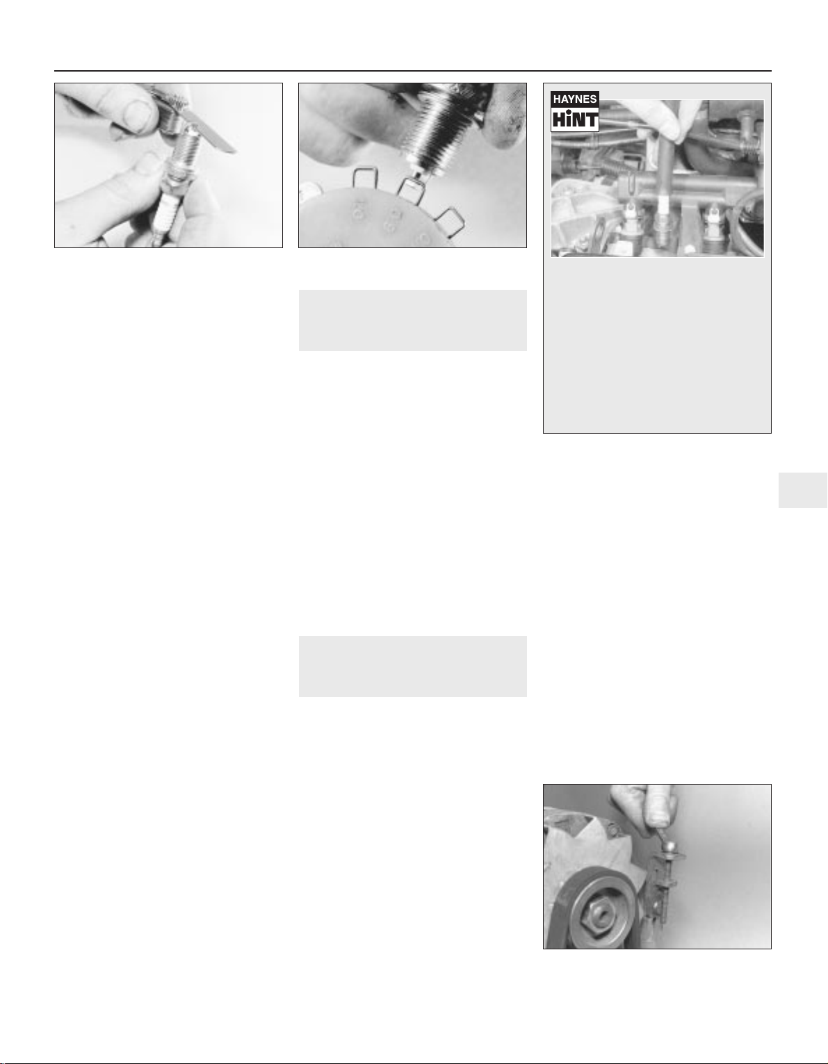
Keep the socket aligned with the spark plug if it is forcibly moved to one side, the ceramic
insulator may be broken off. As each plug is
removed, examine it as follows.
5 Examination of the spark plugs will give a
good indication of the condition of the engine.
If the insulator nose of the spark plug is clean
and white, with no deposits, this is indicative
of a weak mixture or too hot a plug (a hot plug
transfers heat away from the electrode slowly,
a cold plug transfers heat away quickly).
6 If the tip and insulator nose are covered
with hard black-looking deposits, then this is
indicative that the mixture is too rich. Should
the plug be black and oily, then it is likely that
the engine is fairly worn, as well as the mixture
being too rich.
7 If the insulator nose is covered with light tan
to greyish-brown deposits, then the mixture is
correct and it is likely that the engine is in
good condition.
8 The spark plug electrode gap is of
considerable importance as, if it is too large or
too small, the size of the spark and its
efficiency will be seriously impaired. The gap
should be set to the value given in the
Specifications at the beginning of this Chapter.
9 To set the gap, measure it with a feeler
blade, and then bend open, or closed, the
outer plug electrode until the correct gap is
achieved (see illustration). The centre
electrode should never be bent, as this may
crack the insulator and cause plug failure, if
nothing worse. If using feeler blades, the gap
is correct when the appropriate-size blade is a
firm sliding fit.
10 Special spark plug electrode gap
adjusting tools are available from most motor
accessory shops, or from some spark plug
manufacturers (see illustration).
11 Before fitting the spark plugs, check that
the threaded connector sleeves are tight, and
that the plug exterior surfaces and threads are
clean (see Haynes Hint).
12 Remove the rubber hose (if used), and
tighten the plug to the specified torque using
the spark plug socket and a torque wrench.
Refit the remaining spark plugs in the same
manner.
13 Connect the HT leads in their correct
order, and refit any components removed for
access.
8 Throttle and choke cable
lubrication and adjustment
1
1 The throttle cable is connected to a
spring-loaded reel which pivots on the face of
the cylinder head. On certain models, the reel
then operates the throttle lever on the
carburettor through a plastic balljointed
control rod.
2 Sparingly apply a few drops of light oil to
the throttle spindles, linkage pivot points and
to the cable itself. Similarly lubricate the
exposed ends of the choke cable (where
fitted).
3 Check that there is a small amount of
slackness in the cable so that the throttle
linkage closes fully with the accelerator pedal
released. Also check that full throttle can be
obtained with the accelerator pedal fully
depressed.
4 If there is any doubt about the cable
adjustment, refer to the relevant Parts of
Chapter 4 for the full adjustment procedure.
9 Auxiliary drivebelt check and
renewal
2
1 Depending on specification, either one or
two auxiliary drivebelts are fitted. Where two
belts are fitted, it will obviously be necessary
to remove the outer belt in order to renew the
inner belt.
Checking the auxiliary drivebelt
condition
2 Apply the handbrake, then jack up the front
of the car and support it on axle stands.
Remove the right-hand front roadwheel.
3 From underneath the front of the car, prise
out the retaining clips, and remove the plastic
cover from the wing valance where necessary,
to gain access to the crankshaft
sprocket/pulley bolt.
4 Using a suitable socket and extension bar
fitted to the crankshaft sprocket/pulley bolt,
rotate the crankshaft so that the entire length
of the drivebelt(s) can be examined. Examine
the drivebelt(s) for cracks, splitting, fraying or
damage. Check also for signs of glazing (shiny
patches) and for separation of the belt plies.
Renew the belt if worn or damaged.
5 If the condition of the belt is satisfactory,
check the drivebelt tension as described below.
Auxiliary drivebelt - removal,
refitting and tensioning
Removal
6 If not already done, proceed as described
in paragraphs 2 and 3.
7 Disconnect the battery negative lead.
8 Slacken both the alternator upper and lower
mounting nuts/bolts (as applicable).
9 Push the alternator toward the engine until
the belt is slack then slip the drivebelt from
the pulleys. Where an adjuster bolt is fitted,
back off the adjuster to relieve the tension in
the drivebelt, then slip off the belt (see
illustration).
Refitting
10 If the belt is being renewed, ensure that
the correct type is used. Fit the belt around
the pulleys, and take up the slack in the belt
Every 12 000 miles or 12 months 1•11
1
7.9 Measuring the spark plug gap with a
feeler blade
7.10 Measuring the spark plug gap with a
wire gauge
9.9 Slackening the alternator adjuster bolt
to release the auxiliary drivebelt
It is very often difficult to insert spark
plugs into their holes without crossthreading them. To avoid this
possibility, fit a short length of 5/16 inch
internal diameter rubber hose over the
end of the spark plug. The flexible hose
acts as a universal joint to help align
the plug with the plug hole. Should the
plug begin to cross-thread, the hose
will slip on the spark plug, preventing
thread damage to the aluminium
cylinder head

by moving the alternator by hand, or
tightening the adjuster bolt.
11 Tension the drivebelt as described in the
following paragraphs.
Tensioning
12 If not already done, proceed as described
in paragraphs 2 and 3.
13 Correct tensioning of the drivebelt will
ensure that it has a long life. A belt which is
too slack will slip and perhaps squeal.
Beware, however, of overtightening, as this
can cause wear in the alternator bearings.
14 The belt should be tensioned so that,
under firm thumb pressure, there is
approximately 5.0 mm of free movement at
the mid-point between the pulleys on the
longest belt run.
15 To adjust, with the upper mounting
nut/bolt just holding the alternator firm, and
the lower mounting nut/bolt loosened, lever
the alternator away from the engine, or turn
the adjuster bolt until the correct tension is
achieved. Rotate the crankshaft a couple of
times, recheck the tension, then securely
tighten both the alternator mounting
nuts/bolts. Where applicable, also tighten the
bolt securing the adjuster strap to its
mounting bracket.
16 Reconnect the battery negative lead.
17 Refit the plastic cover to the wing valance.
Refit the roadwheel, and lower the vehicle to
the ground.
10 Clutch pedal stroke
adjustment
1
1 The clutch pedal stroke adjustment is
checked by measuring the clutch pedal travel.
Before doing this, settle the cable by
depressing and releasing it a few times.
2 Ensure that there are no obstructions
beneath the clutch pedal then measure the
distance from the centre of the clutch pedal
pad to the base of the steering wheel with the
pedal in the at-rest position. Depress the
clutch pedal fully to the floor, and measure the
distance from the centre of the clutch pedal
pad to the base of the steering wheel (see
illustration).
3 Subtract the first measurement from the
second to obtain the clutch pedal travel. If this
is not with the range given in the
Specifications at the start of this Chapter,
adjust the clutch as follows.
4 On models fitted with the BH3
transmission, loosen the locknut and turn the
adjuster on the transmission intermediate
lever pushrod as necessary. On all other
models, slacken the locknut and turn the
adjuster nut on the end of the cable.
5 Check the pedal stroke again and make
further adjustments as necessary. When all is
correct, tighten the relevant locknut.
11 Seat belt check
1
Check the seat belts for satisfactory
operation and condition. Inspect the webbing
for fraying and cuts. Check that they retract
smoothly and without binding into their reels.
Check the seat belt mountings, ensuring
that all the bolts are securely tightened.
12 Lock and hinge check and
lubrication
1
1 Check that the doors, bonnet and tailgate
close securely. Check that the bonnet safety
catch operates correctly. Check the operation
of the door check straps.
2 Lubricate the hinges, door check straps,
the striker plates and the bonnet catch
sparingly with a little oil or grease.
3 If any of the doors, bonnet or tailgate/boot
lid do not close effectively or appear not to be
flush with the surrounding panels, carry out
the relevant adjustment procedures contained
in Chapter 11.
13 Rear brake shoe check -
models with rear drum brakes
3
Remove the rear brake drums, and check the
brake shoes for signs of wear or contamination.
At the same time, also inspect the wheel
cylinders for signs of leakage, and the brake
drum for signs of wear. Refer to the relevant
Sections of Chapter 9 for further information.
14 Rear brake pad condition
check - models with rear disc
brakes
1
1 Chock the front wheels, then jack up the
rear of the vehicle and support it on axle
stands (see “Jacking and vehicle support”).
Remove the rear roadwheels.
2 For a quick check, the thickness of friction
material remaining on each brake pad can be
measured through the top of the caliper body.
If any pad’s friction material is worn to the
specified thickness or less, all four pads must
be renewed as a set.
3 For a comprehensive check, the brake pads
should be removed and cleaned. This will
permit the operation of the caliper to be
checked, and the condition of the brake disc
itself to be fully examined on both sides. Refer
to Chapter 9 for further information.
15 Handbrake check and
adjustment
2
Refer to Chapter 9.
16 Underbody and fuel/brake
line check
1
1 With the vehicle raised and supported on
axle stands (see “Jacking and vehicle
support”), or over an inspection pit,
thoroughly inspect the underbody and wheel
arches for signs of damage and corrosion. In
particular, examine the bottom of the side
sills, and any concealed areas where mud can
collect. Where corrosion and rust is evident,
press and tap firmly on the panel with a
screwdriver, and check for any serious
corrosion which would necessitate repairs. If
the panel is not seriously corroded, clean
away the rust, and apply a new coating of
underseal. Refer to Chapter 11 for more
details of body repairs.
2 At the same time, inspect the treated lower
body panels for stone damage and general
condition.
3 Inspect all of the fuel and brake lines on the
underbody for damage, rust, corrosion and
leakage. Also make sure that they are
correctly supported in their clips. Where
applicable, check the PVC coating on the
lines for damage.
4 Inspect the flexible brake hoses in the
vicinity of the calipers, where they are
subjected to most movement. Bend them
between the fingers (but do not actually bend
them double, or the casing may be damaged)
and check that this does not reveal
previously-hidden cracks, cuts or splits.
17 Exhaust system check
1
1 With the engine cold (at least three hours
after the vehicle has been driven), check the
complete exhaust system, from its starting
point at the engine to the end of the tailpipe.
Ideally, this should be done on a hoist, where
unrestricted access is available; if a hoist is not
available, raise and support the vehicle on axle
stands (see “Jacking and vehicle support”).
1•12 Every 12 000 miles or 12 months
10.2 To check the clutch pedal stroke,
measure the clutch pedal travel as
described in the text
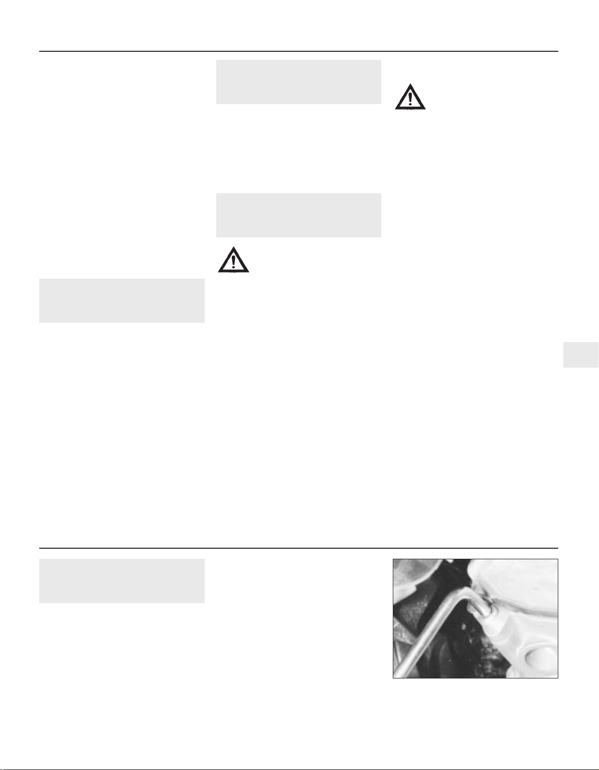
2 Check the pipes and connections for
evidence of leaks, severe corrosion, or
damage. Make sure that all brackets and
rubber mountings are in good condition, and
tight; if any of the mountings are to be
renewed, ensure that the replacements are of
the correct type. Leakage at any of the joints
or in other parts of the system will usually
show up as a black sooty stain in the vicinity
of the leak.
3 At the same time, inspect the underside of
the body for holes, corrosion, open seams,
etc. which may allow exhaust gases to enter
the passenger compartment. Seal all body
openings with silicone or body putty.
4 Rattles and other noises can often be
traced to the exhaust system, especially the
rubber mountings. Try to move the system,
silencer(s) and catalytic converter. If any
components can touch the body or
suspension parts, secure the exhaust system
with new mountings.
18 Bodywork, paint and exterior
trim check
1
1 The best time to carry out this check is after
the car has been washed so that any surface
blemish or scratch will be clearly evident and
not hidden by a film of dirt.
2 Starting at one front corner check the
paintwork all around the car, looking for minor
scratches or more serious dents. Check all
the trim and make sure that it is securely
attached over its entire length.
3 Check the security of all door locks, door
mirrors, badges, bumpers, radiator grille and
wheel trim. Anything found loose, or in need
of further attention should be done with
reference to the relevant Chapters of this
manual.
4 Rectify any problems noticed with the
paintwork or body panels as described in
Chapter 11.
19 Headlight beam alignment
check
1
Accurate adjustment of the headlight beam
is only possible using optical beam-setting
setting equipment, and this work should
therefore be carried out by a Peugeot dealer
or service station with the necessary facilities.
Basic adjustments can be carried out in an
emergency, and further details are given in
Chapter 12.
20 Air conditioning system
check
1
Warning: The air conditioning
system is under high pressure.
Do not loosen any fittings or
remove any components until
after the system has been discharged. Air
conditioning refrigerant must be properly
discharged into an approved type of
container, at a dealer service department
or an automotive air conditioning repair
facility capable of handling the refrigerant
safely. Always wear eye protection when
disconnecting air conditioning system
fittings.
1 The following maintenance checks should
be performed on a regular basis, to ensure
that the system continues to operate at peak
efficiency:
a) Check the auxiliary drivebelt. If it’s worn
or deteriorated, renew it.
b) Check the system hoses. Look for cracks,
bubbles, hard spots and deterioration.
Inspect the hoses and all fittings for oil
bubbles and seepage. If there’s any
evidence of wear, damage or leaks, renew
the hose(s).
c) Inspect the condenser fins for leaves,
insects and other debris. Use a “fin
comb” or compressed air to clean the
condenser.
Warning: Wear eye protection
when using compressed air!
d) Check that the drain tube from the front
of the evaporator is clear - note that it is
normal to have clear fluid (water) dripping
from this while the system is in operation,
to the extent that quite a large puddle can
be left under the vehicle when it is parked.
2 It’s a good idea to operate the system for
about 30 minutes at least once a month,
particularly during the winter. Long term
non-use can cause hardening, and
subsequent failure, of the seals.
3 Because of the complexity of the air
conditioning system and the special
equipment necessary to service it, in-depth
repairs are not included in this manual, apart
from those procedures covered in Chapter 3.
4 The most common cause of poor cooling is
simply a low system refrigerant charge. If a
noticeable drop in cool air output occurs, the
following quick check will help you determine
if the refrigerant level is low.
5 Warm the engine up to normal operating
temperature.
6 Place the air conditioning temperature
selector at the coldest setting, and put the
blower at the highest setting. Open the doors
- to make sure the air conditioning system
doesn’t cycle off as soon as it cools the
passenger compartment.
7 With the compressor engaged - the clutch
will make an audible click, and the centre of
the clutch will rotate - feel the inlet and outlet
pipes at the compressor. One side should be
cold, and one hot. If there’s no perceptible
difference between the two pipes, there’s
something wrong with the compressor or the
system. It might be a low charge - it might be
something else. Take the vehicle to a dealer
service department or an automotive air
conditioning specialist.
21 Manual transmission oil level
check
2
Note: The following procedure is only
applicable to models produced after
approximately October 1986. There is no
provision on the transmission for fluid level
checking on earlier transmissions (see Chapter
7A). Suitable square-section wrench may be
required to undo the transmission filler/level
plug on some models. These wrenches can be
obtained from most motor factors or your
Peugeot dealer.
1 Park the car on a level surface. The oil level
must be checked before the car is driven, or
at least 5 minutes after the engine has been
switched off. If the oil is checked immediately
after driving the car, some of the oil will
remain distributed around the transmission
components, resulting in an inaccurate level
reading.
2 Prise out the retaining clips and remove the
access cover from the left-hand wheelarch
liner.
3 Wipe clean the area around the filler/level
plug, which is situated on the left-hand end of
the transmission (see illustration). Unscrew
the plug and clean it; discard the sealing
washer.
Every 12 000 miles or 12 months 1•13
1
21.3 Using a square section wrench to
unscrew the transmission filler/level plug
(MA transmission shown)
Every 24 000 miles or 2 years
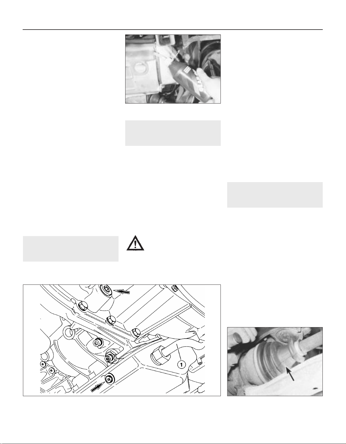
4 The oil level should reach the lower edge of
the filler/level hole. A certain amount of oil will
have gathered behind the filler/level plug, and
will trickle out when it is removed; this does
not necessarily indicate that the level is
correct. To ensure that a true level is
established, wait until the initial trickle has
stopped, then add oil as necessary until a
trickle of new oil can be seen emerging (see
illustration). The level will be correct when
the flow ceases; use only good-quality oil of
the specified type (refer to “Lubricants, fluids
and capacities”).
5 Filling the transmission with oil is an
extremely awkward operation; above all, allow
plenty of time for the oil level to settle properly
before checking it. If a large amount is added
to the transmission, and a large amount flows
out on checking the level, refit the filler/level
plug and take the vehicle on a short journey
so that the new oil is distributed fully around
the transmission components, then recheck
the level when it has settled again.
6 If the transmission has been overfilled so
that oil flows out as soon as the filler/level
plug is removed, check that the car is
completely level (front-to-rear and side-toside), and allow the surplus to drain off into a
suitable container.
7 When the level is correct, fit a new sealing
washer to the filler/level plug. Refit the plug,
tightening it to the specified torque wrench
setting. Wash off any spilt oil then refit the
access cover securing it in position with the
retaining clips.
22 Manual transmission oil
renewal
3
This service requirement is only applicable
to pre-1988 BE1 transmissions. Refer to the
procedures contained in Chapter 7A.
23 Automatic transmission fluid
renewal
2
1 Take the vehicle on a short run, to warm the
transmission up to normal operating
temperature.
2 Park the car on level ground, then switch off
the ignition and apply the handbrake firmly.
For improved access, jack up the front of the
car and support it securely on axle stands.
Note that, when refilling and checking the fluid
level, the car must be lowered to the ground,
and level, to ensure accuracy.
3 Remove the dipstick, then position a
suitable container under the transmission. The
transmission has two drain plugs: one on the
sump, and another on the bottom of the
differential housing (see illustration).
Warning: If the fluid is hot, take
precautions against scalding.
4 Unscrew both drain plugs, and allow the
fluid to drain completely into the container.
Clean the drain plugs, being especially careful
to wipe any metallic particles off the magnetic
insert. Discard the original sealing washers;
these should be renewed whenever they are
disturbed.
5 When the fluid has finished draining, clean
the drain plug threads and those of the
transmission casing. Fit a new sealing washer
to each drain plug, and refit the plugs to the
transmission, tightening each securely. If the
car was raised for the draining operation, now
lower it to the ground. Make sure that the car
is level (front-to-rear and side-to-side).
6 Refilling the transmission is an awkward
operation, adding the specified type of fluid to
the transmission a little at a time via the
dipstick tube. Use a funnel with a fine-mesh
gauze, to avoid spillage, and to ensure that no
foreign matter enters the transmission. Allow
plenty of time for the fluid level to settle
properly.
7 Once the level is up to the “MAX” mark on
the dipstick, refit the dipstick. Start the
engine, and allow it to idle for a few minutes.
Switch the engine off, then recheck the level,
topping-up if necessary. Take the car on a
short run to fully distribute the new fluid
around the transmission, then recheck the
fluid level as described in Section 5.
24 Driveshaft bellows check
1
With the vehicle raised and securely
supported on stands (see “Jacking and
vehicle support”), turn the steering onto full
lock, then slowly rotate the roadwheel.
Inspect the condition of the outer constant
velocity (CV) joint rubber bellows, squeezing
the bellows to open out the folds (see
illustration). Check for signs of cracking,
splits or deterioration of the rubber, which
may allow the grease to escape, and lead to
water and grit entry into the joint. Also check
the security and condition of the retaining
clips. Repeat these checks on the inner CV
joints. If any damage or deterioration is found,
the bellows should be renewed as described
in Chapter 8.
At the same time, check the general
condition of the CV joints themselves by first
holding the driveshaft and attempting to
rotate the wheel. Repeat this check by holding
1•14 Every 24 000 miles or 2 years
21.4 Topping-up the transmission oil level
23.3 Automatic transmission fluid drain plugs (arrowed). Transmission is refilled via the
dipstick tube (1)
24.1 Check the condition of the driveshaft
bellows (arrowed)
 Loading...