

Page 1
Microchip
User’s Guide
Manual d’utilisation
Návod na použití
Guía del usuario
Guida d’uso
Benutzerhandbuch
Please read this entire guide before installation. Veuillez
lire le manual avant de commencer l’installation. Lees
deze handleiding in zijn geheel door vóór installatie.
Por favor lea esta guía por completo antes de llevar a cabo la
instalación. Prima dell’installazione, leggere questa guida per intero.
Před instalací si pečlivě prostudujte návod na použití.
First Edition
Page 2

Explanation of Attention Words and Symbols used in this guide
This is the safety alert symbol. It is used to alert you to potential personal injury hazards. Obey all safety
messages that follow this symbol to avoid possible injury or death.
WARNING indicates a hazardous situation which, if not avoided, could result in death or serious injury.
CAUTION, used with the safety alert symbol, indicates a hazardous situation which, if not avoided, could result
in minor or moderate injury.
NOTICE is used to address practices not related to personal injury.
_______________________________________________________________________________________
When children are present in the home, it is important to consider the pet door during child proofing activities, the pet
door may be misused by a child resulting in the child accessing potential hazards that may be on the other side of the
pet door. Purchasers/Homeowners with swimming pools should ensure that the pet door is monitored at all times and
that the swimming pool has adequate barriers to entry. If a new hazard is created inside or outside of your home, which
may be accessed through the pet door, Radio Systems® Corporation recommends that you properly guard access to the
hazard or remove the pet door. The closing panel or lock, if applicable, is provided for aesthetic and energy efficiency
purposes and is not intended as a security device. Radio Systems® Corporation will not be liable for unintended use and
the purchaser of this product accepts full responsibility for oversight of the opening it creates.
• Power Tools. Risk of severe injury; follow all safety instructions for your power tools.
• Be sure to always wear your safety goggles.
The user, prior to installation, must become familiar with all building codes that may affect the installation of the pet
door and determine, along with a licensed contractor, its suitability in a given installation. This pet door is not a
fire door. It is important for the owner and contractor to consider any risks that may be present inside or outside of
the pet door, and any risks that may be created by subsequent changes to your property and how they may relate
to the existence and use, including misuse of the pet door.
• Keep these instructions with important papers; be sure to transfer these instructions to the new owner of the property.
• Please read these instructions fully prior to forming or modifying an opening in your selected door or wall. We strongly
recommend that your Petporte smart flap® is assembled, powered up and programmed for your cat and a
check made that it works with the microchip in your cat first.
• We do not accept responsibility for incorrect operation of the unit should modifications be made to the antenna
coil. Under no circumstances should you alter or adjust the windings of the antenna coil.
• This unit only operates properly when outside temperatures are greater than -15° C and less than 55° C
(greater than 5° F and less than 131° F).
• Installation in a Metal Door: Prior to installation it is recommended to check if the Petporte smart flap® will operate
properly with your metal door. To do this, hold the assembled and programmed Petporte smart flap® up to the metal
door and bring your cat up to porch. If the lock releases, the door will function properly when installed.
2
Page 3
Your Staywell® Pet Door...
Thank you for choosing Staywell® by PetSafe®. Our mission is to be the most trusted brand in the pet ownership experience. We
want to ensure your pet’s safety by providing you with the products and techniques to create the most comfortable lifestyle for your
pet. If you have any questions, please contact the Customer Care Centre. For a listing of Customer Care Centre telephone
numbers, visit our website at www.petsafe.net.
To get the most protection out of your warranty, please register your product within 30 days at www.petsafe.net. By registering
and keeping your receipt, you will enjoy the product’s full warranty and should you ever need to call the Customer Care Centre,
we will be able to help you faster. Most importantly, Staywell® by PetSafe® will never give or sell your valuable information to
anyone. Complete warranty information is available online at www.petsafe.net.
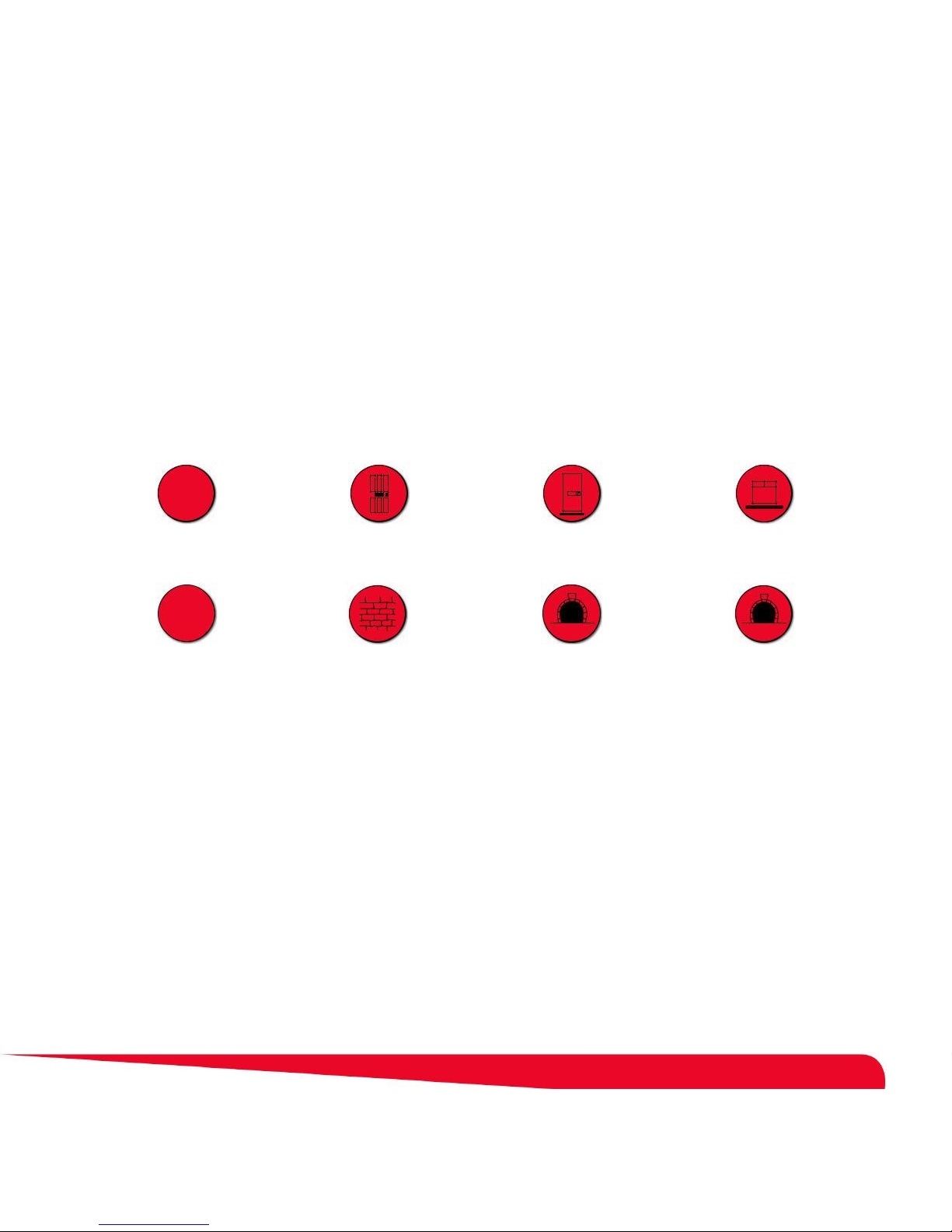
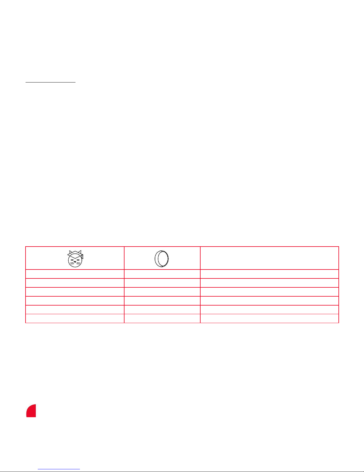
Cat Fits wooden doors Fits PVC/uPVC/metal
Microchip
Fits brick walls
Optional tunnel included is
R.F.I.D.
†
suitable for most thickness
of doors
Fits glass windows & doors,
single and double glazed*
Additional tunnel extensions
available
All Staywell® by Petsafe® Microchip Cat Flaps are suitable to fi t any door or partition although additional materials and
competent DIY skills may be required.
Note: This cat flap is designed as a retrofi t for Staywell® by PetSafe® 300, 400, 500 and 900 series cat flaps. Some simple DIY
skills are required. Minor adjustments to the cut-out are needed.
* It is not possible to cut holes in toughened glass or double glazed units except at the time of manufacture. Please consult a glazier.
† Microchip R.F.I.D. (Radio Frequency Identifi cation)
3
Page 4

Table of Contents
Included with the Petporte smart flap
®
............................................................................................................................. 5
Tools Required ............................................................................................................................................................................. 6
How it Works ................................................................................................................................................................ ................. 6
Petporte smart flap® Assembly (For Testing Purposes Prior to Installation) ................................................. 7
Programming Cats Into the Petporte smart flap
®
........................................................................................................ 7
Checklist for all installations .................................................................................................................................................. 8
Measurement and Marking .................................................................................................................................................... 8
Petporte smart flap® Installation Into a Non-Glass Door ......................................................................................... 9
Petporte smart flap® Installation Into Glass Doors or Windows ........................................................................... 9
Petporte smart flap® Installation into Walls .................................................................................................................. 10
Assembly Instructions............................................................................................................................................................. 10
Petporte smart flap® Quick Guide .................................................................................................................................... 13
Extended Modes - Quick Guide ......................................................................................................................................... 14
Operating Modes ...................................................................................................................................................................... 15
Extended Modes ....................................................................................................................................................................... 16
LED Indicator - Quick Guide ................................................................................................................................................ 18
Battery Backup Facility .......................................................................................................................................................... 18
Training Your Cat to Use the Cat Flap ................................ ................................................................ ........................... 19
Accessories ................................................................................................ ................................................................ ................. 19
Cleaning the Cat Flap ................................................................................................................................ ............................. 19
Disable the Cat Flap ................................................................................................................................................................ 19
Battery Disposal ................................................................................................ ................................ ........................................ 20
Important recycling advice.................................................................................................................................................... 20
Compliance .................................................................................................................................................................................. 20
Terms of Use and Limitation of Liability ................................ ................................................................ ......................... 20
Français ....................................................................................................................................................................................... 21
Nederlands ................................................................................................................................................................................. 40
Español ........................................................................................................................................................................................ 59
Italiano ................................................................................................................................................................ .......................... 78
Deutsch ........................................................................................................................................................................................ 97
4
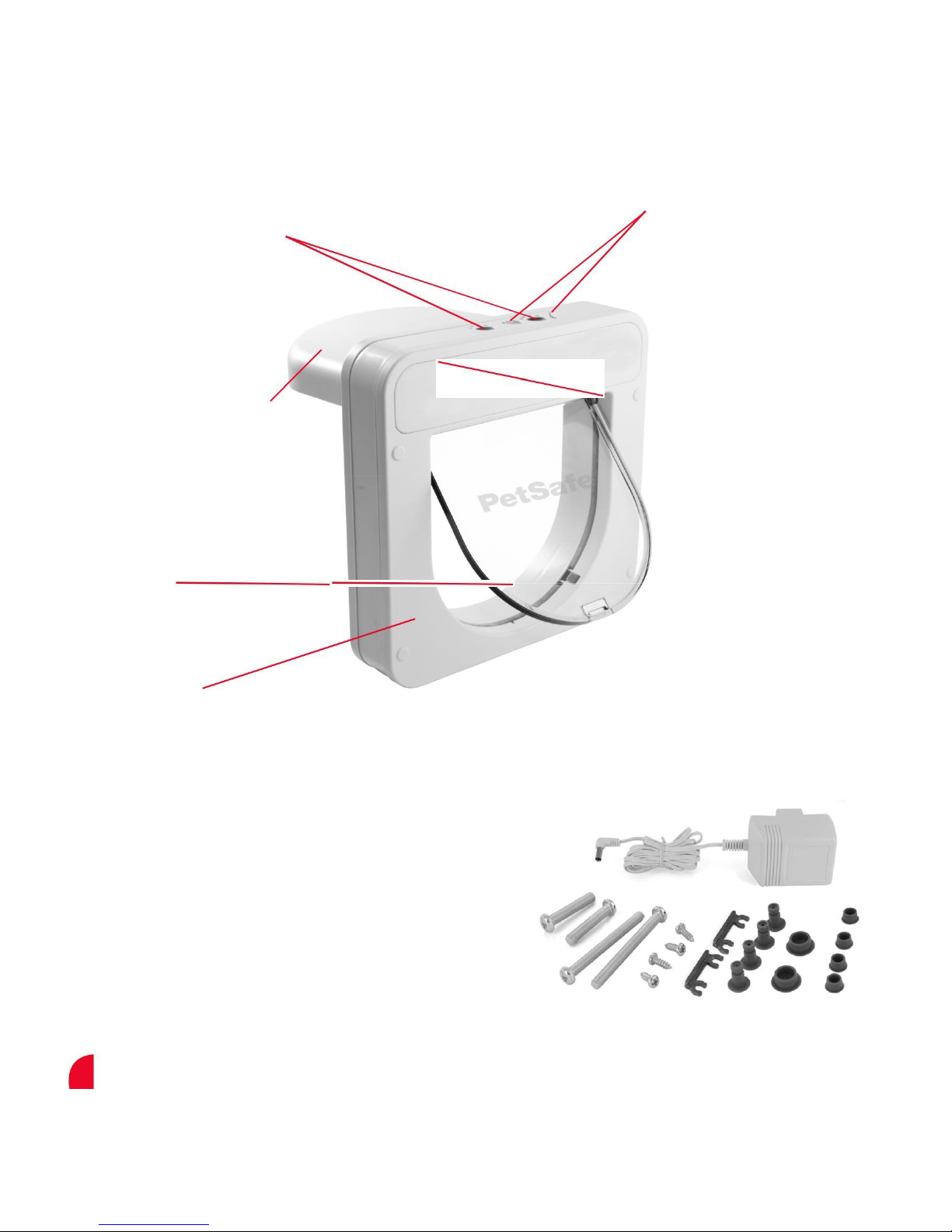
Page 5
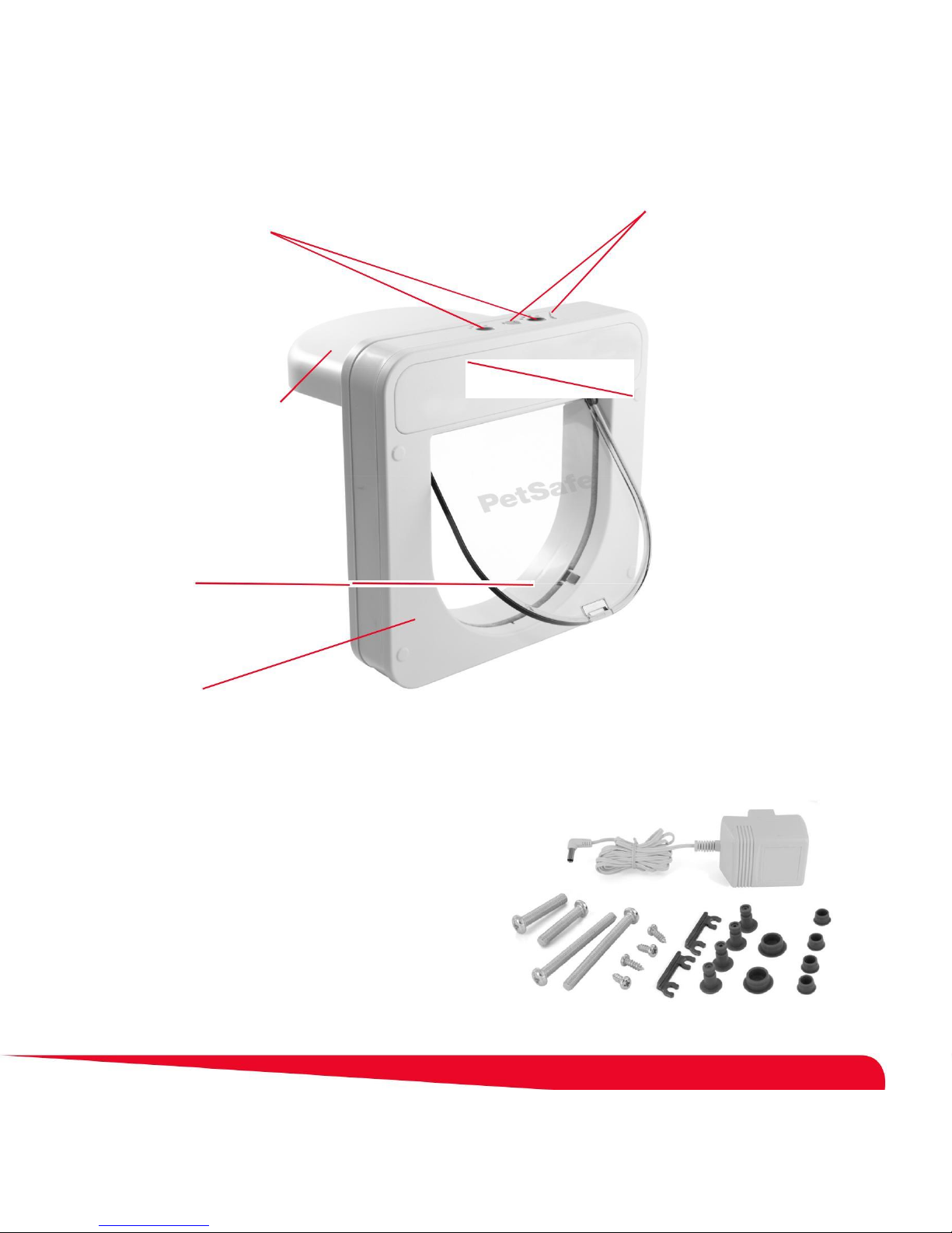
Program buttons LED Indicator Lights (Cat / Moon)
(Red & Green paw shaped)
Outside Inside
Porch with Microchip scanner Small Cover plate
Green - In Lock Red - Out Lock
Large Cover Plate
Included with the Petporte smart flap® :
Cutting Template
Power Supply
2 - Large M6 Screws
4 - Self-Tapping Fixing Screws
2 - Horseshoe Clips
4 - Mushroom Pins
2 - Large Blanking Plugs
4 - Small Blanking Plugs
2 - Small M6 Screws (For installation into glass doors or windows)
5
Page 6
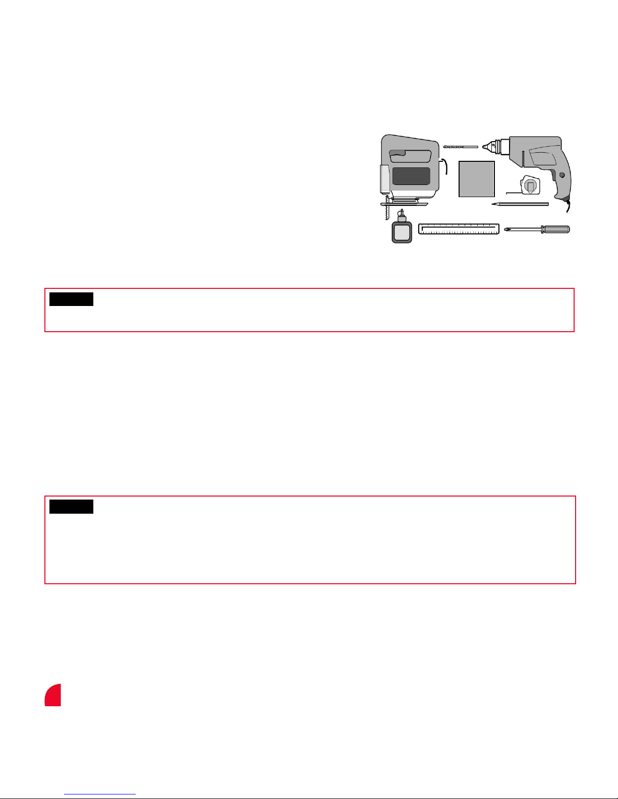
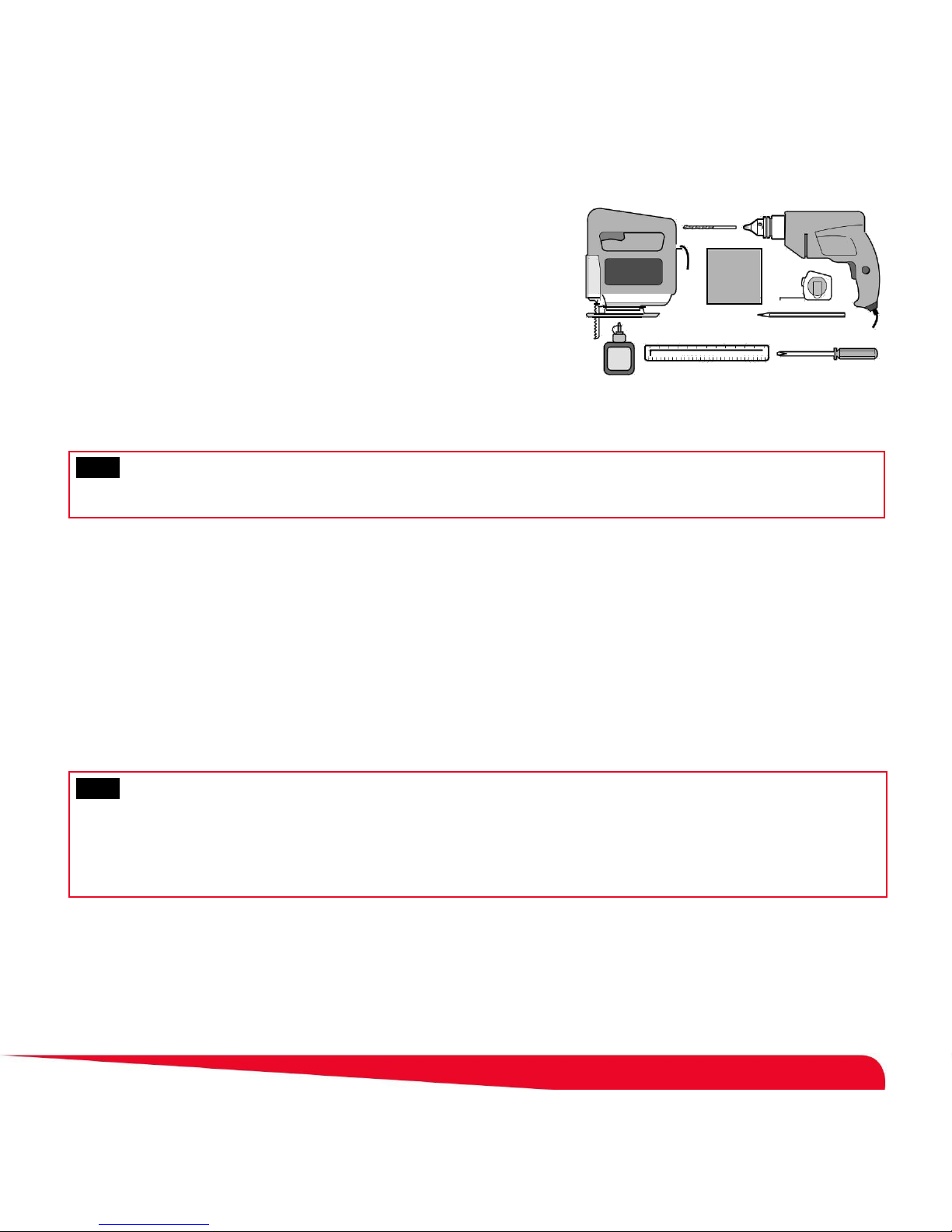
Tools required
• Pencil
• Screwdriver
• Ruler
• Tape measure
• Jig or Keyhole Saw
• Glue
• Electric Drill
• Sand paper
• 7 mm Drill bit
During installation great care must be taken using drills or other cutting equipment. If you are at all in doubt then please hire
the services of a qualifi ed professional to fi t the cat fl ap for you.
We do not accept any responsibility for openings that are formed or modifi ed in doors or walls. We do not accept any
responsibility for damage caused to doors or walls in the forming or modifi cation of such openings or any costs associated with
the repair or reinstatement of doors or walls.
How it Works
Your Petporte smart fl ap® Microchip Cat Flap has been designed to allow your animals easy access to the outside world whilst keeping
other troublesome cats out of your house. The Petporte smart fl ap® cat fl aps do not require your animals to wear collars or accessories.
The Petporte smart fl ap® Microchip Cat Flap reads the unique identifi cation number stored on your cat’s microchip that your vet
has implanted in your animal. Whenever your cat passes under the porch of the cat fl ap, the system scans the unique number
and, if that number matches the number already programmed in for that cat, it will unlock the cat fl ap and allow the animal to
enter. If the animal has not been programmed into the system then the number scanned will not match and the cat fl ap will
remain locked preventing access to your property.
If you are not sure whether your cat has a microchip, then just ask your vet to scan for it. The Petporte smart fl ap® is designed
to read the most common type of microchip, the FDX-B (15 digit): it will not read other types of microchips. If you are not sure
what type of microchip your cat has, then please either ask your vet or visit www.petsafe.net and navigate to our Chip Checker
microchip compatibility checker to verify that your microchip is compatible.
Please read these instructions fully prior to forming or modifying an opening in your selected door or wall.
We strongly recommend that your Petporte smart fl ap® is assembled, powered up and programmed for your cat and a check
made that it works with the microchip in your cat fi rst.
Installation in a Metal Door: Prior to installation it is recommended to check if the Petporte smart fl ap® will operate properly with
your metal door. To do this, hold the assembled and programmed Petporte smart fl ap® up to the metal door and bring your cat
up to porch. If the lock releases, the door will function properly when installed.
Whilst the Petporte smart fl ap® works with the most common microchips used in the United Kingdom and Europe (FDX–B 15
digit microchips) there are a small number of cats that have microchips without the necessary range to reliably operate the
Petporte smart fl ap®. Occasionally microchips migrate to positions within the cat that the scanner cannot read reliably. In these
cases the Petporte smart fl ap® can only be used as a cat fl ap without the selective entry. Therefore, before the Petporte smart fl
ap® is actually fi tted to the selected door or wall we strongly advise you that your Petporte smart fl ap® unit should be assembled,
powered up, programmed for your cat and that you have ensured that the unit will work with the microchip in your animal at the
same distance as your cat will be approaching the Petporte smart fl ap® when it is installed.
6
Page 7

Petporte smart flap® Assembly (For Testing Purposes Prior to Installation)
Important: Before assembling or disassembling the unit, always ensure that the power is turned off and any
installed battery is removed. (see Figures on page 10-12)
1. Offer the porch up to the front of the exterior section of the cat fl ap (see Figure 1), ensuring that the wire and connector pass
through the battery compartments on the porch and exterior sections.
2. Insert the four plastic “mushroom” pins through the holes on the reverse side of the exterior section of the Petporte smart fl ap®
and through the porch (see Figure 2).
3. From the inside of the porch, secure the plastic “mushroom” pins in place with the “horseshoe” clips (see Figure 3).
4. Next, remove the Extension Tunnel from the interior section and remove the four self-tapping fi xing screws from the large cover
plate separating it from the main unit (see Figure 4).
5. Remove the transparent door fl ap.
6. Feed the Porch Cable from the porch and through the battery compartment on the interior section (see Figure 5). Mount the
exterior section with attached porch over the tunnel molding on the interior section.
7. Temporarily attach the external and interior sections using the two supplied M6 screws through the exterior section and
loosely screw into the interior section (see Figure 6a).
8. Connect the porch wire and connector onto the electronics board. Any excess cable should be routed to the right of the battery
compartment (see Figure 6b).
9. Attach the low voltage power cable to the power connector on the left of the electronics board and route the cable along the cable guides so
that the wire passes through one of the slots at the bottom of the Petporte smart fl ap® (see Figure 7). Do not plug in or turn on the power.
Alternatively, or in addition to the power cable, attach a 9-volt PP3 battery and insert into the battery compartment below the electronics board.
10. Replace the transparent door fl ap ensuring that the ridge around the door is inward facing.
11. Place the large cover plate over the interior section and loosely screw in place using the four self tapping screws for testing purposes (see Figure 8).
12. If not already in position click the small cover plate in place over the battery compartment (see Figure 9).
13. Power up your Petporte smart fl ap® by plugging in and/or turning on the mains supply or temporarily activate the battery by gently pushing the
transparent door fl ap against the green lock to activate a switch. There will be a small mechanical click. Only use the power supply included
with the product. Using an unauthorised power supply will invalidate your guarantee and may damage the cat fl ap.
14. Now please refer to the programming instructions (below) to record your cat’s microchip number into your Petporte smart fl ap®. Once your cat
is programmed you need to ensure that the Petporte smart fl ap® can reliably read the microchip at the distance that your cat will approach it
when installed. Repeat this for all of your cats that you want to be programmed in (see Figure 10a and 10b).
_______________________________________________________________________________________
Programming Cats Into the Petporte smart flap®
Because your Petporte smart fl ap® is initially supplied unprogrammed, when it is fi rst powered both the green and red lights will fl
ash to indicate that there are no animals programmed in the unit. The door locks will also open, allowing free access for any animal
to enter or exit. When programming the Petporte smart fl ap® with an animal for the fi rst time or if you exceed the programming
time, ensure that your pet is nearby as you have 30 seconds in which to introduce the animal to the scanner (porch). You may wish
to enlist the help of another person, as cats are naturally suspicious of anything new!
Press and hold the Green Button for about 10 seconds until the green light stays illuminated and then release the Green Button. A beep
should sound and the red light should stop fl ashing with only the green light left fl ashing. You now have 30 seconds to pass the cat
underneath the porch. There is no need to post the cat through the Petporte smart fl ap® as this can lead to unnecessary stress for the
animal. Microchips are normally implanted between the shoulder blades of the animal; it is that part of the animal that needs to be under
the porch area in order to program the unique identifi cation number for that animal. Once the microchip has been successfully scanned,
the Petporte smart fl ap® will beep three times. The green light will stop fl ashing, and the green lock will come up to its locked position.
If this procedure fails the fi rst time or if you exceed the programming time, simply repeat the process.You will need to program
the unit with each of your cats by using this method. Your Petporte smart fl ap® can be programmed with up to 25 cats.
Only once you are completely satisfied that your Petporte smart flap® works with all your cats’ microchips,
prepare to install your Petporte smart flap®.
7
Page 8
Checklist for all installations:
Before positioning the Petporte smart fl ap® it is important to consider the following points.
If fitted into a door: Will any of the components of the Petporte smart fl ap® be obstructed by the door opening and closing?
If fitted into a wall: Are there any objects such as doors that could open on to the Petporte smart fl ap® once it is fi tted?
Where is the closest power outlet? Your Petporte smart fl ap® is supplied with a low voltage power supply that has a 2.5 m
(8’) electrical cable. If your nearest power outlet is more than 2.2 m (7’) away then you will require an Extension Lead. Please
refer to the Accessories section for information on purchasing a 5 m Extension Lead.
Battery operation alone. For reliable and fast operation we recommend the use of the external power supply included with the
Petporte smart fl ap®. However, an optional 9-volt PP3 battery may be plugged in so that during power cuts your cat will still be
able to use the cat fl ap. We recommend the use of a good quality non-rechargeable lithium battery in order to give the longest
battery life. Please note that there are certain options that are not available when the Petporte smart fl ap® is powered by
batteries: Automatic Night Mode and Wall Installations.
When the Petporte smart fl ap® is being powered by the external power supply, the scanner is scanning all the time for your
cat’s microchip and therefore will normally register and unlock the cat fl ap before your cat is at the transparent door fl ap. When
using batteries, your cat will need to push the transparent door fl ap in order to activate the microchip scanner. If your cat just
sits outside the cat fl ap then it will not activate the scanner and will not allow access.
Extension tunnels for doors over 52 mm (2.05”) thick and walls. Please note that the Petporte smart fl ap® comes with an
extension tunnel to fi t doors up to 52 mm (2.05”) thick. If your installation requires a tunnel longer than this, extra tunnel sections,
each providing 40 mm (1.6”) of additional length, are available . Please refer to the Accessories section for information on purchasing
additional Extension Tunnels. Extension Tunnels can be stacked together by glueing and pushing them together.
Is there a large step down from your door? The ideal height of the cat fl ap is such that the base of the unit is at the same
height as your cat’s stomach. However, due to door construction, it may not always be possible to mount any cat fl ap this low
and in these circumstances it is recommended that the Petporte smart fl ap® should be installed as low down on the door as is
possible. If necessary, a little step can be installed which will help reduce the distance from the scanner porch to the cat’s
microchip (as long as it is not going to become a tripping hazard for people).
If there is an existing opening in your door, is it greater than 212 mm (8 3/8”) diameter (circular) or 171 mm wide X 180
mm tall? If an existing opening in your door or wall is greater than these dimensions, then it is acceptable to fi t the Petporte
smart fl ap®, providing the indoor and outdoor cover plates cover the opening. If the opening is larger than the indoor and
outdoor cover plates, the Petporte smart fl ap® may be fi tted by replacing the door panel or constructing panels to cover the
existing opening so that a smaller opening can be cut.
_______________________________________________________________________________________
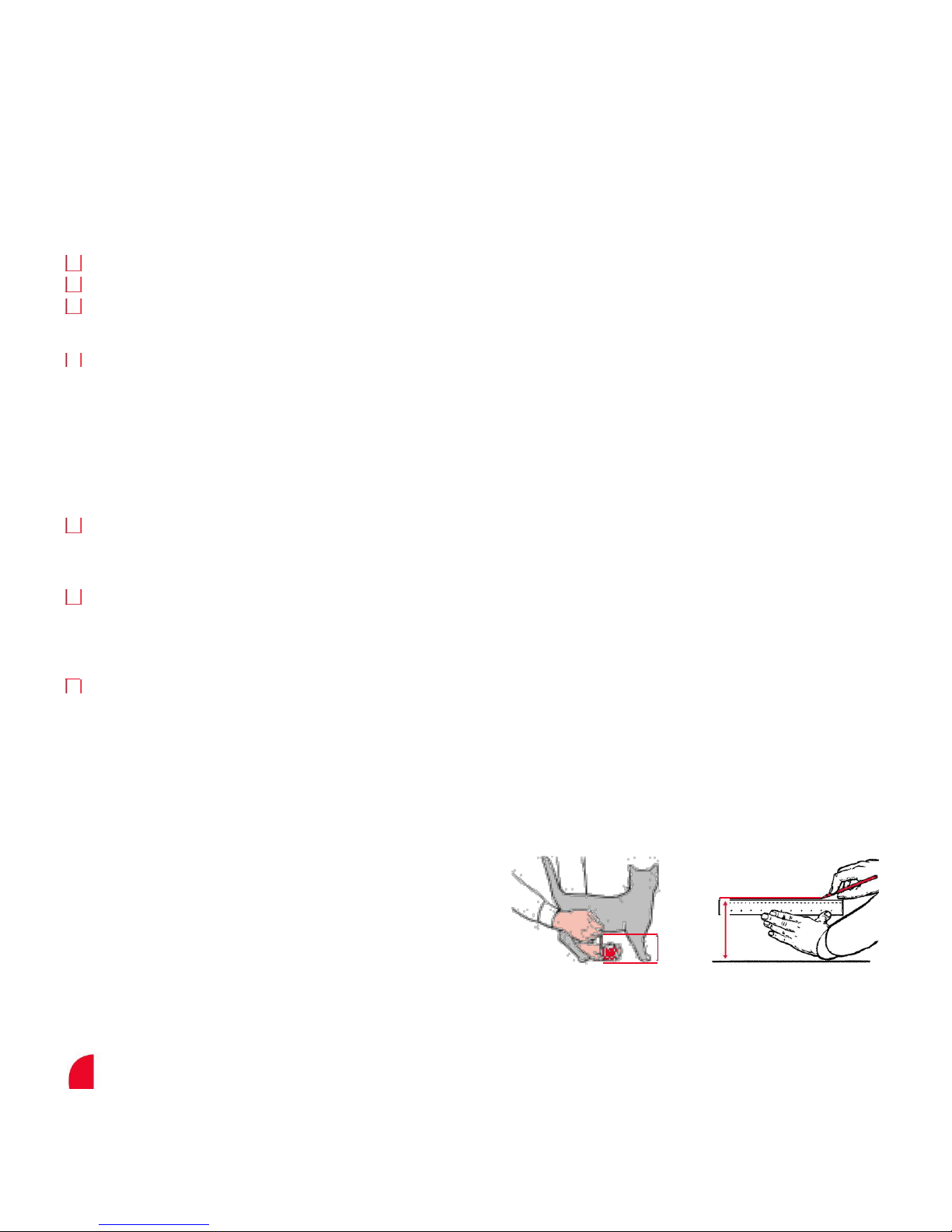
Measurement and marking
Fig. A
Fig. B
Measure the belly height of your cat. This is usually 100 mm -150 mm
(4” - 6”) (Figure A).
Mark this measurement on the outside of your door and draw a
straight horizontal line 171 mm (6 3/4”) (Figure B).
Please bear in mind that this line will eventually be the bottom of the
X
hole you will cut in your door and that the frame of the cat fl ap will be
(x)
slightly lower. If necessary, this line may have to be raised slightly to
account for this.
8
Page 9

Petporte smart flap® Installation Into a Non-Glass Door
1. Attach the supplied Cutting Template to the outside of your door in the selected position ensuring that it is the right way up and is level.
2. Drill the two holes with a 7 mm (9/32”)-diameter drill bit as marked on the Cutting Template into the house door.
3. Cut out the large hole as marked on the Cutting Template by the dashed line. When cutting this hole, keep to the outside of
the dashed line to ensure that there is clearance for the Extension Tunnel.
4. Clean the area from any dust, dirt, or debris.
Note: Follow Steps 5-9 if you completed the assembly instructions (for testing) on page 7.
5. If the low voltage power supply is plugged in to the mains, unplug it.
6. Remove the interior four self-tapping fi xing screws, the large interior cover plate, and transparent door.
7. Remove the two M6 screws, which hold the exterior and the interior sections together.
8. Remove the battery, if attached.
9. Unplug the porch cable connector from the electronics board.
10. Mount the interior section through the hole with any additional Extension Tunnel sections that are required. (see Figure 11)
11. Feed the Porch Cable from the porch and external section through the door and through the rectangular opening on the
interior section. Mount the exterior section on the outside of the door over the Extension Tunnel.
12. Put the supplied M6 screws through the exterior section and screw into the interior section. Please note depending on
the thickness of your door you may need to cut the screw length down.
13. Push the Porch Cable connector onto the electronics board. Any excess cable must be routed to the right of the
battery compartment. Ensure the cable does not lay on top of the electronics board. (see Figure 12a and 12b)
14. If you require an extension lead, then plug it into the electronics board rather than the power supply. The provided power
supply then connects in the extension lead.
15. If you do not require an extension lead, attach the power cable to the power connector on the electronics board. Route the cable
along the cable guides so that the wire passes through one of the slots at the bottom of the cat fl ap closest to the power supply.
16. Replace the transparent door fl ap ensuring that the ridge around the door is facing inward.
17. Reattach the interior large cover plate using the four self tapping fi xing screws.
18. If a battery is to be used as an alternative or in addition to the power supply then attach a 9-volt PP3 battery and insert into
the battery compartment within the internal section. Click the small cover plate into place over the battery compartment.
19. When the installation of your Petporte smart fl ap® is completed, place the two blanking plugs over the screws on the exterior
frame and the four blanking plugs on the interior frame. (Figure 13)
20. If you select not to use the Petporte smart fl ap® utilising battery power alone, plug in the power supply. Your Petporte smart fl
ap® is now ready to use.
_______________________________________________________________________________________
Petporte smart flap® Installation Into Glass Doors or Windows
The Petporte smart fl ap® is also designed for installation into glass and requires a circular hole of diameter 212 mm (8 3/8”). Working with
glass is a skilled job and should be carried out by a professional glazier. Your glazier will need to cut a circular hole of diameter 212 mm (8
3
/8”) as per the glass template. If you are in any doubt then please consult with your glazier about the fi tting of the Petporte smart fl ap®.
Once a suitable opening is formed, then install cat fl ap as described for a non-glass door beginning with step 5.
Note: Two, small M6 screws have been included.
.
9
Page 10
Petporte smart flap® Installation into Walls
Wall fi xing screws are not provided with this catfl ap as the type needed will vary greatly depending on the wall construction.
Various fi xing types are available from hardware and D.I.Y. stores depending on the wall construction: chemifi x bolts and nuts,
screws fi xed into inter-set or plastic rawl plugs, nylon self drill or polytoggle.
1. An opening must be formed in the wall at the appropriate height and size for your cat to be scanned, based on the Cutting Template provided. The
opening should be formed by a qualifi ed builder avoiding utility supplies and not damaging the integrity of buildings damp-proof courses.
The principle difference between fi tting the Petporte smart fl ap® through a wall and a door is the method of fi xing the interior
and exterior sections to the wall.
2. To fi x the interior section to the wall utilise the four, 5 mm diameter holes in the corners of the interior section that are
accessible with the large interior cover plate removed.
3. To fi x the exterior section to the wall utilise the two, 6 mm diameter holes in the sides of the exterior section that support the porch.
The Petporte smart fl ap® comes with a single Extension Tunnel that provides 52 mm length. Extra Extension Tunnels can be
purchased, with each individual tunnel providing 40 mm additional length. These are not provided with the Petporte smart fl ap® because
wall thicknesses vary. Some consumers prefer to form their own tunnels by using marine grade plywood or other materials.
Please refer to the Accessories section of this guide for information on purchasing additional Extension Tunnels.
We do not accept responsibility for incorrect operation of the unit should modifi cations be made to the antenna
coil. Under no circumstances should you alter or adjust the windings of the antenna coil.
_______________________________________________________________________________________
Assembly Instructions
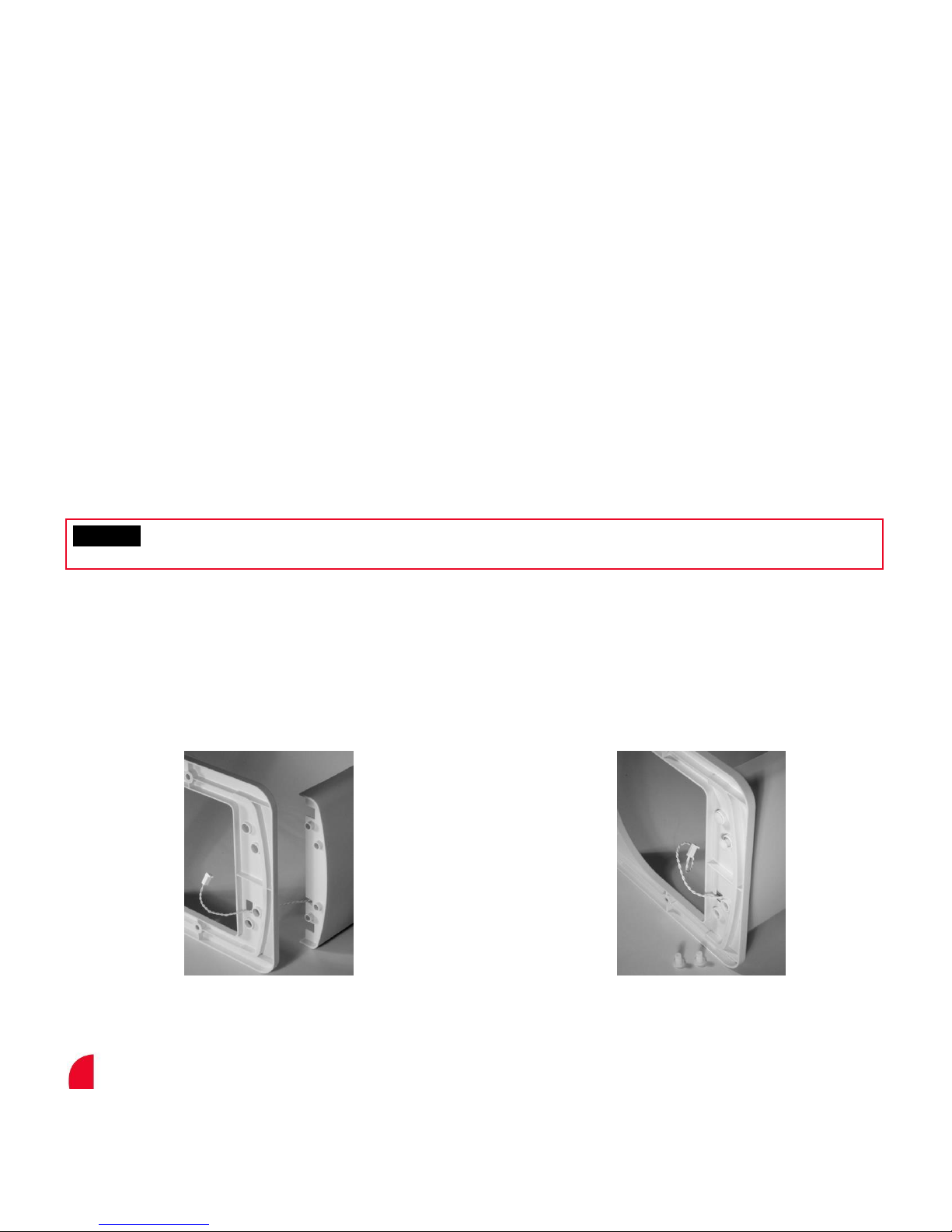
Fig. 1 Fig. 2
Pass the porch cable from the porch
through the small rectangular
opening in the exterior section.
Pass the four “mushrooms”
pins through the back of the
exterior section into the porch.
10
Page 11
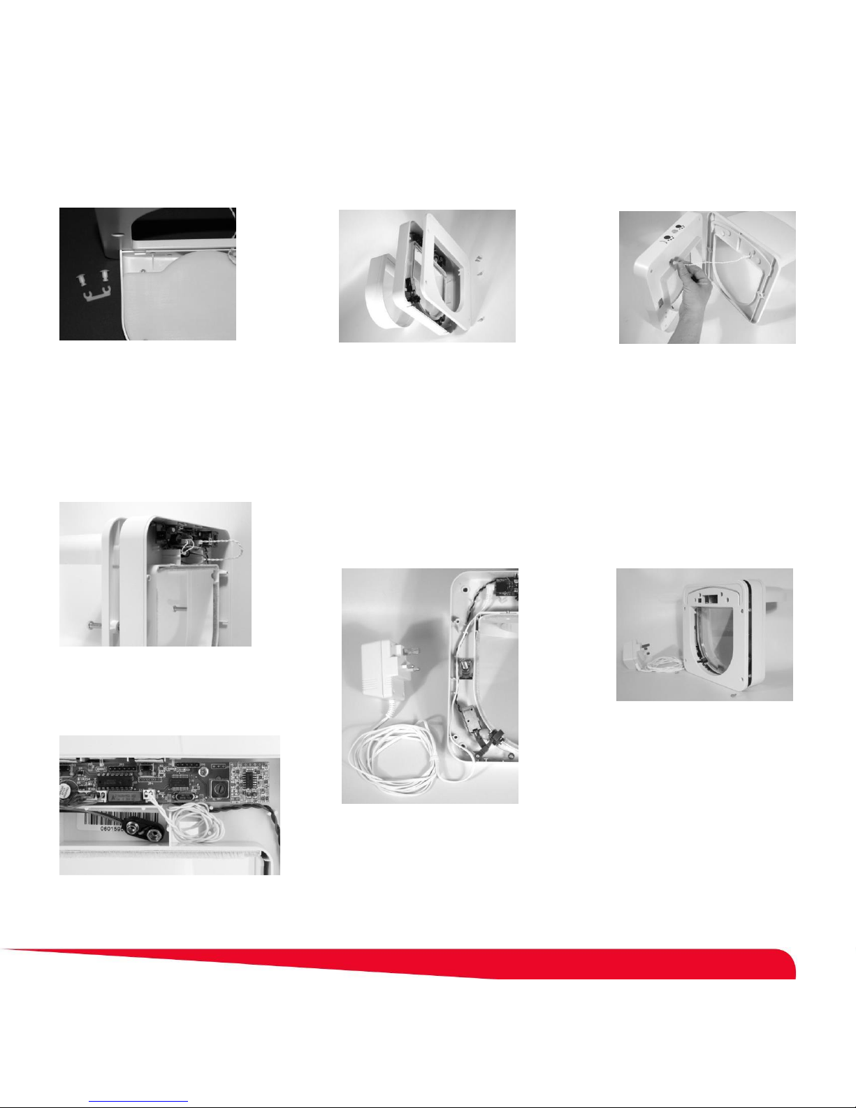
Fig. 3
Attach the “horseshoe” clips to
the four “mushrooms” pins on the
underside of the porch.
Fig. 6a
Fig. 4
Remove the extension tunnel
from the interior section.
Loosen the four self-tapping fi
xing screws from the interior
section and remove the large
cover plate.
Fig. 7
Fig. 5
Pass the porch cable from the
porch and exterior section
through the rectangular
opening in the interior section.
Fig. 8
Temporarily attach the porch and
exterior section to the interior
section with the two M6 screws.
Fig. 6b
Attach the porch cable to the
electronics board as shown. Any
excess cable must be routed to the
right of the battery compartment.
Attach the low voltage power
supply connector to the
electronics board and pass the
power cable through the clips
and out the opening at the
bottom of the interior section.
Replace the large cover plate
to the interior section and
temporarily secure with the
four self-tapping fi xing screws.
11
Page 12
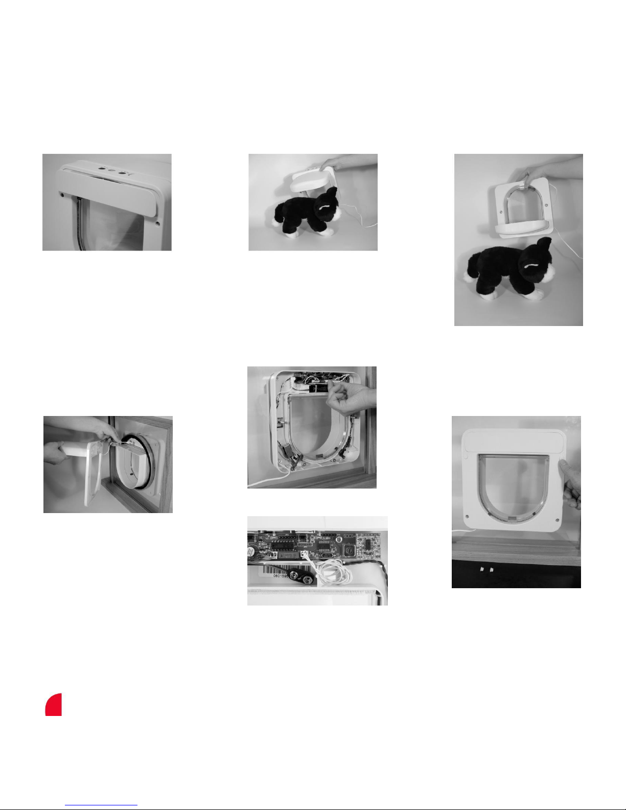
Fig. 9 Fig. 10a Fig. 10b
Click the small cover plate
back over the interior section.
Fig. 11
When fi tting the Petporte
smart fl ap® into an opening
offer the interior section with
Extension Tunnel if needed up
to the opening. Next pass the
porch cable from the porch
and exterior section through
the rectangular opening in the
interior section.
Power up the Petporte smart
fl ap®, program in your cat as
shown on page 7, and pass the
Petporte smart fl ap® over your
cat at a distance that your cat
would normally approach it to
check that will work for your cat.
Fig. 12a
Fig. 12b
Attach the porch cable to the
electronics board and hold the
exterior and interior sections
together using the two M6 screws.
Tighten the screws to hold the
Petporte smart fl ap® in the desired
position within the opening.
Alternatively you can hold the
Petporte smart fl ap® in an
inverted orientation for the
purpose of programming
your cat’s microchip.
Fig. 13
Once positioned, attach the large
cover plate and secure with the four
self-tapping fi xing screws. Click in
place the small cover plate. Place all
of the blanking plugs, four small ones
for the self-tapping fi xing screws and
two large blanking plugs for the M6
screws. Finally, power up your
Petporte smart fl ap®.
12
Page 13

Petporte smart flap® Quick Guide
Function
Button Activation
Mode Button Function
Normal Mode
This is the default mode on powering up
and requires no button activation.
Night Mode (Timer Mode)
Press the Red Button for
The red light will illuminate.
less than 2 seconds
In Night Mode: During the hours of
darkness, the green light will illuminate.
The unit will not allow the cat to exit. At
dawn, the green light will extinguish and
the lock opens and the cat can go outside
again until dusk.
In Timer Mode: The unit will Lock and
Unlock at specific programmed times of day.
Vet Mode
Press the Red Button for
The red light will then fl ash and the unit
more than 2 seconds
will not allow any cats to go out.
Program Entry
Press and hold the Green Button for
The green light will fl ash and you then
more than 10 seconds
have 30 seconds in which to program
your cat by passing the animal under
the porch.
Extended Modes
Press and hold both the Red and Green
The unit will emit a long beep indicating
Buttons for more than 2 seconds
that the extended modes are now
available and the green light will be lit.
(See the Extended Modes - Quick Guide
on page 14)
Key Pad Lock
Press and hold the Red Button for
The unit will emit a series of beeps
more than 30 seconds
indicating the unit is now locked.
Erase Mode
Press and hold both the Red and Green
The unit will emit a series of short beeps
Buttons for more than 30 seconds
followed by a long beep. Both lights
should now be fl ashing.
Note: Once the unit’s memory has been
erased, it will have to be re-programmed
before further use!
Reset to Normal Mode
Press and hold the Green Button for
The unit will emit a series of short beeps
more than 30 seconds
followed by a long beep. Both lights
should extinguish. Hold both buttons
down simultaneously for more than 30
seconds and UPON RELEASE the unit
emits a long beep.
13
Page 14

Extended Modes - Quick Guide
Please see page 16 for a full explanation of each Extended Mode.
Press and hold both the Red and Green Buttons simultaneously for more than 2 seconds and then release to enter the Extended Mode menu.
When in Extended Modes, the green light illuminates and you start in Exit Mode. Modes are selected by pressing the Red Button
to go “up” a mode and the Green Button to go “down” a mode. The current mode is indicated by a number of beeps. When you are
in the mode you require a quick press of both buttons simultaneously will activate that mode.
No. of Beeps
Mode
Function
1
Exit Mode
Cancels the extended mode option system and returns the Petporte smart
fl ap® to a normal mode of operation.
2
Open Mode
The green light will fl ash and the green lock will lower allowing any cat
access through the Petporte smart fl ap®.
3
Silent Mode
The audible beep will no longer sound when your cat is recognised by the
Petporte smart fl ap®.
4
Set Light Level Mode
Sets the desired light level for which the cat fl ap will lock and unlock during
Night Mode operation.
5
Lock Return Time
The default time for your Petporte smart fl ap®’s locks to return to their
locked positions after your cat’s microchip has been recognised is 4
seconds. However, should you have a particularly timid cat, or if your cat is
frequently chased by other cats, the lock return time can be lengthened or
shortened.
6
Low Battery Lock State
If, when the Petporte smart fl ap® is running in battery mode, the battery
charge runs low, the Petporte smart fl ap® has a built in option to allow the
locks to be set at a specifi ed open or closed position.
7
Timer Mode
Sets the specifi c times of day for which the cat fl ap will lock and unlock
during Night Mode operation.
14
Page 15

Operating Modes
Normal Mode
This is the default mode on powering the cat fl ap and will allow only your cat(s) to enter.
Night Mode
For a variety of reasons, many pet owners prefer their animals not to go outside at night. The Petporte smart fl ap® provides a mode
whereby it will automatically prevent your pet from going outside during hours of darkness and the cat fl ap will automatically unlock
when daylight dawns. If your pet is already outside when darkness falls, the system will still allow the animal to enter.
The Night Mode also allows pet owners to set the specifi c time of day that they want the unit to lock and unlock (Timer Mode).
To employ this mode, press the Red button for less than 2 seconds and then release it. The unit will beep and the red light will il-
luminate to inform you that it is in Night Mode (Timer Mode).
• At the pre-set LOCK time or when darkness falls, the green light will illuminate, indicating that the cat fl ap will be locked.
• At the pre-set UNLOCK time or when dawn arrives, the green light will extinguish, indicating that the cat fl ap will be unlocked.
Note: Night mode can take up to 30 seconds to start functioning.
Vet Mode
If you are intending to take your pet to the vet, or just want it to stay inside, then the Petporte smart fl ap® provides a mode whereby
your cat can enter but will not be allowed out again.
To employ this mode, press the Red Button for 5 seconds, or until the red light begins to fl ash, and then release it. The unit will then
beep and the red light will start to fl ash, indicating that the cat fl ap is locked and your cat cannot go out.
To exit this mode, press the Red Button again for 5 seconds, or until the red light begins to fl ash, and then release it. The unit
will beep again and the red light will extinguish.
Extended Modes
The Petporte smart flap® has a number of extended modes that allow you to customise the Petporte smart flap® to suit your individual needs.
For information on how to use the Extended Modes please see the Extended Modes section on page 19 of this user guide.
Key Pad Lock
If you wish to lock the buttons on your Petporte smart fl ap® (this is helpful in preventing children from adjusting the modes), press
and hold the Red Button for 30 seconds. The unit should begin to beep repeatedly. Release the Red Button and the unit will be set
to Key Pad Lock.
To re-enable the button controls and disable the Key Pad Lock, repeat the above process.
Erase Mode
If you wish to erase all programmed animal identifi cation numbers from the system’s memory, please use the following procedure.
However, it must be noted that once the memory has been erased, you will have to re-program the unit with any animals that are to
use the cat fl ap. Therefore, please ensure that you really wish to erase the memory before proceeding.
To erase all microchip numbers, press and hold both the Red and Green Buttons for 30 seconds. The unit should begin to beep
repeatedly. Release both the Red and Green buttons and the unit should emit a long beep and both lights should begin to fl ash,
indicating that the memory has been erased.
Note: Once the unit’s memory has been erased, it will have to be re-programmed before further use!
Reset to Normal Mode
Should you wish to reset your Petporte smart fl ap® back to its Normal Mode and exit modes such as Night Mode, Vet Mode or
Open Mode, please use the following procedure.
Press and hold the Green Button for more than 30 seconds, or until the unit emits a series of short beeps, before releasing the
button. The unit should emit a long beep and all lights should extinguish, indicating the Petporte smart fl ap® is in it’s Normal
Mode of operation. Returning to Normal Mode will not erase your cat’s programmed microchip numbers or the variable functions
available in the Extended Modes.
15
Page 16

Extended Modes
The Petporte smart fl ap®’s “extended mode” system gives you the opportunity to tailor the Petporte smart fl ap® to your
individual requirements.
To enter the Extended Modes menu, press both the Red and Green Buttons simultaneously for 2 seconds, or until both lights begin
to fl ash, and then release them. The Petporte smart fl ap® should beep and the green light will come on to inform you that you have
now entered the fi rst of the Extended Mode menu options.
When in “extended mode”, the modes are selected by pressing the Red Button to go “up” a mode and the Green Button to go
“Down” a mode. The current mode is indicated by a number of beeps. When you are in the mode you require, a quick press of
both buttons simultaneously will activate that mode. See page 14 for a table of available extended modes. If no buttons are
pressed within a 20 second period, the Petporte smart fl ap® will beep and the green light will extinguish, indicating that the unit has
gone back to its normal mode of operation.
Exit Mode (leave Extended Modes) - 1 Beep
This is the fi rst mode in the Extended Mode menu. It is indicated by a single audible beep. This option simply cancels the “extended mode” and puts the Petporte smart fl ap® back into a normal mode of operation. To activate Exit Mode, quickly press both Red
and Green buttons simultaneously.
Open Mode - 2 Beeps
In the unlikely event that you wish to have the Petporte smart fl ap® open to allow any animal entry, the Petporte smart fl ap® provides a mode whereby any animal (be it microchipped or not) can enter through the Petporte smart fl ap®. Enter the extended
modes by pushing the Red and Green buttons simultaneously for more than 2 seconds then push the red button once to enter
Open Mode which will be indicated by 2 beeps. Then, to activate Open Mode and exit the extended modes quickly press both Red
and Green buttons simultaneously.
When Open Mode is activated the unit will emit a long beep and the green light should fl ash to show the unit is in Open Mode.
To de-activate Open Mode, activate the Open Mode once more. The unit will again emit a long beep and the green light should
extinguish, indicating the Petporte smart fl ap® has returned to a normal mode of operation.
Silent Mode 3 - Beeps
Each time that a recognised animal enters or leaves via the Petporte smart fl ap® the unit will emit a short beep. To silence this
beep, activate the Silent Mode. Enter the Extended Modes by pushing the Red and Green buttons simultaneously for more than 2
seconds then push the red button once (the unit will emit 2 beeps) then again to enter Silent Mode which will be indicated by 3
beeps. Then to activate silent mode and exit the extended modes quickly press both buttons simultaneously. A short beep should
be heard, following which no further beeps will be emitted whenever your pet enters or exits the Petporte smart fl ap®.
To turn the beep back on, activate the Silent Mode once more. The unit will again emit a short beep, following which a short beep
will be emitted whenever your pet enters or exits the Petporte smart fl ap®.
Set Light Level Mode - 4 Beeps
When the Petporte smart fl ap® is set to Night Mode the light sensor detects a pre-determined level of ambient light and locks or
un-locks the Petporte smart fl ap® accordingly.
If you wish to alter when the Petporte smart fl ap® locks or unlocks in Night mode, simply activate the Set Light Level mode, in the
morning or evening, when the outside light is enough for your cat to be safely outside. Make sure that your indoor lights are
switched off when you re-set the light level; otherwise they may infl uence the light sensor. Enter the Extended Modes by pressing
the Red and Green buttons simultaneously for more than 2 seconds, then press the red button once (the unit will beep twice), then
press the red button again (the unit will beep 3 times) then press the red button once again and the unit will beep 4 times as you
enter Set Light Level Mode. To select the current light level, at which you want the door to lock or unlock, press the Red and Green
buttons simultane-ously. The unit will emit a beep and exit the Extended Modes.
16
Page 17

You must now activate Night Mode so that the unit recognizes the light levels that you have programmed and locks or
unlocks appropriately. To activate Night Mode, press the Red button for less than 2 seconds.
Note: The light level setting will remain in memory even if you lose power to your Petporte smart fl ap®. The light sensor will be
affected by internal lights, external security lights or street lights.
Lock Return Time - 5 Beeps
The default time for your Petporte smart fl ap®’s locks to return to their locked positions after your cat’s microchip has been
recognised is 4 seconds. However, should you have a particularly timid cat, or if your cat is frequently chased by other cats, the lock
return time can be lengthened or shortened by the following procedure.
Enter the Extended Modes by pushing the Red and Green buttons simultaneously for more than 2 seconds, then press the red button
once (the unit will beep twice) then again (the unit will beep three times) then again (the unit will beep four times) the once again and the
unit will beep 5 times and you have arrived at Lock Return Mode. To enter the Lock Return Mode press both buttons simultaneously, the
green light will stay on and the red light will fl ash. Press and hold the Green Button for the desired lockout time of between 1 and 25
seconds before releasing. During this period an audible beep will sound for the duration of the button press, until the Green Button is
released. On releasing the Green Button the Petporte smart fl ap® will return to its normal mode of operation.
Low Battery Lock State - 6 Beeps
If, when the Petporte smart fl ap® is running in battery mode, the battery charge runs low, the Petporte smart fl ap® has a built in
option to allow the locks to be set at a specifi ed open or closed position.
This option, for example, will allow the green lock to be open or locked when the battery is low, allowing or preventing any animal
ac-cess inside the house through the Petporte smart fl ap®. Likewise, the red lock can be set to be open or locked when the battery
is low, allowing or preventing any animal access outside the house through the Petporte smart fl ap®. Enter the Extended Modes by
pushing the Red and Green buttons simultaneously for more than 2 seconds, then press the red button once (the unit will beep
twice) then again (the unit will beep three times) then again (the unit will beep four times) then again (the unit will beep fi ve times)
then once again and the unit will beep 6 times and you have arrived at Low Battery Lock State Mode. To enter Low Battery Lock
State Mode, press both Red and Green buttons simultaneously, the green light will stay illuminated and the unit will emit a beep.
Pressing the Green Button will toggle the green lock state between open and closed, while pressing the Red Button toggles the
red lock state between open and closed.
When both red and green locks are in the required position, a quick press of both Red and Green Buttons simultaneously will result in a
short beep sounding and the Petporte smart fl ap® will exit the Extended Modes menu and return to its normal mode of operation.
Timer Mode – 7 Beeps
When the Petporte smart fl ap® is set to Night Mode, you can also determine the time of day at which you want the cat fl ap to
lock or unlock by using the Timer Mode. The Timer Mode is offered as an alternative to the “Set the Light Level Mode” which is
determined by the ambient light around the door.
To set the UNLOCK time: This function needs to be carried out at the time of day when you wish the unit to OPEN and remain UNLOCKED.
Enter the Extended Modes by pushing the Red and Green buttons simultaneously for more than 2 seconds, then press the red
button once (the unit will beep twice) then again (the unit will beep three times) then again (the unit will beep four times) then again
(the unit will beep fi ve times) then once again (the unit will beep six times) then once again and the unit will beep 7 times and you
have arrived at Timer Mode. To enter Timer Mode, press both Red and Green buttons simultaneously, the green light will stay
illuminated and the red light will fl ash.
Pressing and releasing the Green button quickly will set the UNLOCK time. On releasing the Green button the Petporte smart fl
ap® will return to its normal mode of operation.
17
Page 18
To set the LOCK time: This function needs to be carried out at the time of day when you wish the unit to CLOSE and remain LOCKED.
Enter the Extended Modes by pushing the Red and Green buttons simultaneously for more than 2 seconds, then press the red
button once (the unit will beep twice) then again (the unit will beep three times) then again (the unit will beep four times) then again
(the unit will beep fi ve times) then once again (the unit will beep six times) then once again and the unit will beep 7 times and you
have arrived at Timer Mode. To enter Timer Mode, press both Red and Green buttons simultaneously, the green light will stay
illuminated and the red light will fl ash.
Pressing and releasing the Red button quickly will set the LOCK time. On releasing the Red Button the Petporte smart fl ap® will
return to its normal mode of operation.
You must now activate Night Mode so that the unit recognizes the UNLOCK and LOCK times that you have
programmed. To activate Night Mode, press the Red button for less than 2 seconds.
Note:
1. The Timer Mode will only function when the unit is powered through the external power supply included with this unit. The
Timer Mode is not available when the unit enters battery backup mode.
2. In the event of a power cut, you will need to reset the unlock and lock times.
3. The Timer Mode supersedes the light level detector. The unit will no longer read the ambient light levels to decide if the unit
should be locked or unlocked.
LED Indicator - Quick Guide
Explanation of LED Indicators:
Function
Flash
Flash
Power on but nothing programmed
Off
Off
Normal Operating Mode
Off (Day) / On (Night)
On
Night Mode (Timer Mode)
Off
Flash
Vet Mode
Flash
Off
Open Mode
On
Flash
Battery Level Low
Battery Backup Facility
Your Petporte smart fl ap® has the facility to fi t a backup battery, ensuring your cat can still have access to your house in the event
of a power cut on the low voltage power supply.
To install batteries, remove the small cover plate with a screw driver and attach a 9-volt PP3 battery to the connecting snaps.
Push battery into the battery compartment and snap the small cover plate back in place.
Please note that the following functions are currently unavailable with your Petporte smart flap®, when the unit is being operated by battery alone:
1. Wall Mounting - Currently the Petporte smart fl ap® Battery Backup Facility is unable to function on a wall fi tted unit.
2. Night Mode - Currently Night Mode is unavailable when the unit enters battery backup mode.
18
Page 19

Training your cat to use the cat flap
Most cats will learn to use the cat fl ap almost at once but there are a few who may be a little nervous at fi rst. The following tips will help your pet
to take full advantage of the outdoor freedom and indoor comfort – which you want for your cat – and which your new cat fl ap provides.
The most important rule is to be patient with your cat. Don’t be in a hurry. Let your cat work out for itself that it can go in and out
of doors. Don’t force it through the fl ap or it may become frightened.
Many cat owners install cat fl aps when they move house. If this applies to you, make sure that your cat is familiar with his or her
surroundings before you fi t the cat fl ap. Take it on supervised trips outdoors on a lead and make sure it also feels secure and
comfortable in its new indoor environment. Cats can develop long lasting fears in unfamiliar surroundings.
Once you have installed your cat fl ap, leave the fl ap open for some time. You can do this by using a long strip of masking tape;
open the fl ap and use the tape to keep it held open by fi xing the other end of the tape to the surface above. Make sure that the fi
xing is secure so that the fl ap can not fall down accidentally. Let your cat become familiar with it and go in and out freely.
Establish a motive for your cat to use the door. A good one is food. First feed the cat near the door, inside and then near the door
outside. Repeat as often as you need to. Most cats, especially kittens, also have a strong urge for freedom, perhaps to hunt. Cats are
also social creatures – they enjoy the company of other cats. This can be another reason for them to explore outside.
There are some cats however, who can take a little longer to become more confi dent and familiar with the Petporte smart fl ap® door func-tions.
Use a favourite treat to coax your cat towards and through the cat fl ap and reward them when they get it right. Once your cat is com-
fortable coming through the cat fl ap, you should remove the masking tape and lower the cat fl ap.
Accessories
To purchase additional accessories for your Petporte smart fl ap®, visit our website at www.petsafe.net to locate a retailer near you
and for a listing of Customer Care Centre telephone numbers in your area.
PAC19-12596
Extension Tunnel - White
PAC19-12597
Extension Tunnel - Brown
PAC19-12741
Replacement Flap
PAC19-12753
5 m Extension Lead - Black
PAC19-12598
5 m Extension Lead - White
MPA00-12867
Power Supply - United Kingdom - White
MPA00-12868
Power Supply - Europe - White
MPA00-12869
Power Supply - United Kingdom - Black
MPA00-12870
Power Supply - Europe - Black
MPA00-12766
Hardware Kit
Cleaning the Cat Flap
Your cat fl ap is constructed of the highest quality material with a toughened fl ap and has been designed to last for many
years. To maintain its appearance, occasional wiping with a damp cloth is all that is necessary.
Note: Never use household polish as this may damage the product.
Disable the Cat Flap
If you no longer require the unit to function, the following procedure will allow you to lock the flap and turn off the unit completely.
If a battery is installed in the unit, remove the battery. Put the unit into a Normal Operating Mode so that the green lock is up; use the
Extended Modes - Exit Mode function if necessary. Then, activate the Vet Mode, so the red lock is up by pressing the Red Button for 5
seconds. Next, remove the power adapter and/or extension leads. Both of the locks will stay up and hold the flap into a locked position.
19
Page 20
Battery Disposal
Separate collection of spent batteries is required in many regions; check the regulations in your area before discarding spent
batteries. This device operates on one 9 Volt alkaline battery (PP3/IEC 6LR61). Replace only with equivalent battery. To remove
battery from this device; remove the small cover plate with a screwdriver and separate the battery from the connecting snaps.
Important recycling advice
Please respect the Waste Electrical and Electrical Equipment regulations in your country. This equipment must be recycled. If you no longer
require this equipment, do not place it in the normal municipal waste system. Please return it to where it was purchased in order that it can
be placed in our recycling system. If this is not possible, please contact our Customer Care Centre for further information.
Compliance
Hereby, Radio Systems® Corporation, declares that this Microchip Petporte smart fl ap® Cat Flap is in compliance with the essential requirements
and other relevant provisions of Directive 1999/5/EC (R&TTE). Unauthorised changes or modifi cations to the equipment that are not approved by
Radio Systems® Corporation are in violation of EU regulations, could void the user’s authority to operate the equipment, and void the warranty.
The Declaration of Conformity can be found at: http://www.petsafe.net/customercare/eu_docs.php.
Australia
This device complies with the applicable EMC requirements specifi ed by the ACMA (Australian Communications and
Media Authority).
Terms of Use and Limitation of Liability
1. Terms of Use
Use of this Product is subject to your acceptance without modifi cation of the terms, conditions and notices contained herein. Use of this Product implies acceptance of all
such terms, conditions and notices. If you do not wish to accept these terms, conditions and notices, please return the Product, unused, in its original packaging and at
your own cost and risk to the relevant customer care centre together with proof of purchase for a full refund.
2. Proper Use
This Product is designed for use with pets where training is desired. The specifi c temperament or size/weight of your pet may not be suitable for
this Product (please refer to this Operating Guide for details). Radio Systems® Corporation recommends that this Product is not used if your pet is
aggressive and accepts no liability for determining suitability in individual cases. If you are unsure whether this Product is appropriate for your pet,
please consult your veterinarian or certifi ed trainer prior to use. Proper use includes, without limitation, reviewing the entire Operating Guide and
any specifi c Caution statements.
3. No Unlawful or Prohibited Use
This Product is designed for use with pets only. This pet training device is not intended to harm, injure or provoke. Using this Product in a way that
is not intended could result in violation of Federal, State or local laws.
4. Limitation of Liability
In no event shall Radio Systems® Corporation or any of its associated companies be liable for (i) any indirect, punitive, incidental, special or
consequential damage and/or (ii) any loss or damages whatsoever arising out of or connected with the misuse of this Product. The Purchaser
assumes all risks and liability from the use of this Product to the fullest extent permissible by law. For the avoidance of doubt, nothing in this clause 4
shall limit Radio Systems® Corporation’s liability for human death or personal injury or fraud or fraudulent misrepresentation.
5. Modification of Terms and Conditions
Radio Systems® Corporation reserves the right to change the terms, conditions and notices governing this Product from time to time. If such
changes have been notifi ed to you prior to your use of this Product, they shall be binding on you as if incorporated herein.
20
Page 21

Explication des mots et des symboles d'avertissement utilisés dans ce guide
Ce symbole est une alerte de sécurité. Il est utilisé pour vous alerter des risques de blessures.
Veuillez respecter tous les messages de sécurité qui suivent ce symbole pour éviter tout risque
de blessure ou de décès.
AVERTISSEMENT indique une situation dangereuse qui, si elle n'est pas évitée, pourrait entraîner la
mort ou des blessures graves.
ATTENTION utilisé avec un symbole d'alerte de sécurité, indique une situation dangereuse qui, si
elle n'est pas évitée, pourrait entraîner des blessures légères à modérées.
AVIS indique les pratiques qui ne sont pas relatives aux blessures corporelles.
_______________________________________________________________________________________
Lorsqu'il y a des enfants à la maison, il est important de tenir compte de la chatière pour la sécurité des
enfants; en effet, la chatière peut être mal employée par un enfant et l'exposer à des risques potentiels
éventuellement présents de l'autre côté de la chatière. Les acheteurs propriétaires de piscine doivent
s'assurer que la chatière est surveillée en permanence et que la piscine comporte des barrières adéquates à
l'entrée. Si un nouveau risque se présente à l'intérieur ou à l'extérieur de votre maison, auquel on peut
accéder par la chatière, Radio Systems Corporation® vous recommande de protéger correctement l'accès à
ce risque ou de retirer la chatière. Le panneau d'obturation ou la fermeture, le cas échéant, est fourni pour
des raisons esthétiques et énergétiques et n'est pas conçu comme dispositif de sécurité. Radio Systems
Corporation® ne peut être tenu responsable en cas d'usage involontaire et l'acheteur de ce produit accepte
l'entière responsabilité en ce qui concerne la surveillance de l'ouverture créée.
• Outils électriques. Risque de blessure grave ; suivre l'ensemble des instructions de sécurité de
vos outils électriques.
• Portez toujours vos lunettes de sécurité.
Avant l'installation, l'utilisateur doit se familiariser avec les réglementations de construction qui peuvent affecter
l'installation de la chatière et déterminer, avec l'aide d'un entrepreneur agréé, son caractère approprié dans une
installation donnée. Cette chatière n'est pas une porte coupe-feu. Il est important pour le propriétaire et
l'entrepreneur de prendre en compte tous les risques éventuels à l'intérieur ou à l'extérieur de la chatière, ainsi que
tous les risques entraînés à la suite de modifications ultérieures de votre propriété, et comment ils peuvent avoir un
effet sur l'existence, l'utilisation, et notamment le mauvais usage de la chatière.
• Conservez ces instructions et transférez-les à son nouveau propriétaire, le cas échéant.
• Veuillez lire la totalité de ces instructions avant de réaliser ou de modifier une ouverture dans la porte ou le mur
choisi. Nous vous recommandons fortement d'assembler votre Petporte smart flap®, de le mettre sous tension et de
le programmer pour votre chat, et de vérifier tout d'abord qu'il fonctionne avec la micropuce que porte votre chat.
• Nous rejetons toute responsabilité en cas de fonctionnement incorrect de l'appareil si des modifications
ont été apportées à la bobine d'antenne. L'enroulement de la bobine d'antenne ne doit dans aucune
circonstance être modifié ou ajusté.
• Pour fonctionner correctement ce produit doit être exposé a des températures extérieures -15 ° C et
inférieure à 55 ° C (supérieure à 5 ° F et inférieure à 131 ° F).
• Installation dans une porte métallique : avant l'installation, il est recommandé de vérifier si le Petporte
smart flap® fonctionne correctement avec votre porte métallique. Pour ce faire, tenez le Petporte smart
flap® assemblé et programmé contre la porte métallique et approchez votre chat du porche. Si la
fermeture s'ouvre, la chatière fonctionnera correctement une fois installée.
21
Page 22
FR
Votre chatière Staywell®...
Merci d'avoir choisi Staywell® de chez PetSafe®. Notre objectif est d'être reconnus comme la marque la plus fi able par les
propriétaires d'animaux. Notre volonté est de garantir la sécurité de votre animal en mettant à votre disposition des produits et des
techniques susceptibles de lui assurer le style de vie le plus confortable. Si vous avez des questions, veuillez contacter notre
Service clientèle. Pour connaître les numéros de téléphone du Service clientèle, visitez notre site Internet www.petsafe.net.
Pour bénéfi cier pleinement de votre garantie, veuillez enregistrer votre article dans les 30 jours sur le site www.petsafe.net.
Grâce à cet enregistrement et en conservant le reçu, votre produit sera totalement couvert par notre garantie et si vous deviez
contacter notre service clientèle, nous pourrions vous aider plus rapidement. Enfi n, vous pouvez voir la certitude que Staywell®
de chez PetSafe® ne communique jamais les informations personnelles de ses clients à des tiers. Informations complètes sur la
garantie disponibles sur www.petsafe.net.
Chat
Identifi cation RF de
la micropuce
†
Convient aux portes
en bois
Convient aux murs
en briques
Convient au PVC, au PVC
rigide et au métal
Le tunnel inclus convient
à la majorité des
épaisseurs de portes
Convient aux fenêtres et
aux portes en verre à
simple ou à double vitrage*
Extensions de tunnels
sup-plémentaires
disponibles
Les chatières à micropuce Staywell® de chez Petsafe® s’adaptent à toutes les portes ou cloisons, bien que du matériel
supplémentaire et des compétences en bricolage se révèlent peut-être nécessaires.
Remarque : cette chatière est conçue sous forme de rétro-adaptation pour les chatières Staywell® de chez PetSafe® séries 300,
400, 500 et 900. Des compétences de base en bricolage suffi sent. La découpe nécessite quelques petits ajustements.
* Il n’est pas possible de découper du verre trempé ou un double vitrage sauf au moment de la fabrication. Veuillez consulter un vitrier.
† Identifi cation RF de la micropuce (identifi cation par radiofréquence).
22
Page 23

Table des matières
Éléments inclus avec le Petporte smart flap
®
............................................................................................................. 24
Outils nécessaires .................................................................................................................................................................... 25
Fonctionnement du système ............................................................................................................................................... 25
Assemblage du Petporte smart flap® (à tester avant installation) ..................................................................... 26
Programmation des chats dans le Petporte smart flap
®
........................................................................................ 26
Liste de contrôle pour toutes les installations ............................................................................................................. 27
Mesure et marquage ............................................................................................................................................................... 27
Installation du Petporte smart flap® dans une porte non vitrée .......................................................................... 28
Installation du Petporte smart flap® dans une porte ou fenêtre en verre ....................................................... 28
Installation du Petporte smart flap® dans un mur ..................................................................................................... 29
Instructions d'assemblage .................................................................................................................................................... 29
Guide rapide du Petporte smart flap
®
............................................................................................................................. 32
Modes étendus - Guide rapide ................................................................................................................................ ........... 33
Modes de fonctionnement .................................................................................................................................................... 34
Modes étendus .......................................................................................................................................................................... 35
Voyant DEL - Guide rapide .................................................................................................................................................. 37
Option de batterie de secours ............................................................................................................................................ 37
Pour entraîner votre chat à utiliser la chatière ............................................................................................................ 38
Accessoires ................................................................................................ ................................................................ ................. 38
Nettoyage de la chatière ....................................................................................................................................................... 38
Désactiver la chatière ............................................................................................................................................................. 38
Élimination des batteries usagées .................................................................................................................................... 39
Conseil important concernant le recyclage .................................................................................................................. 39
Conformité .................................................................................................................................................................................... 39
Conditions d'utilisation et limite de responsabilité..................................................................................................... 39
23
Page 24
Boutons de programmation (en Voyants lumineux (chat / lune)
forme de patte, rouge et vert)
Extérieur Intérieur
Porche avec lecteur de Petit cache
micropuce
Fermeture Fermeture
intérieure verte extérieure rouge
Grand cache
Éléments inclus avec le Petporte smart flap® :
Instructions de
découpage Adaptateur
2 - Grandes Vis (M6)
4 - Vis autotaraudeuses
2 - Attaches en fer à cheval
4 - Broches aplaties
2 - Grands bouchons d'obturation
4 - Petits bouchons d'obturation
2 - Petites Vis (M6 – Installation dans une porte ou fenêtre en verre)
24
Page 25
Outils nécessaires
• Crayon
• Tournevis
• Règle
• Ruban à mesurer
• Scie sauteuse ou scie à guichet
• Colle
• Perceuse électrique
• Papier abrasif
• Foret de 7 mm
Pendant l'installation, un soin tout particulier doit être apporté lors de l'utilisation de perceuses ou d'autres appareils de
découpe. Si vous avez le moindre doute, veuillez engager un professionnel qualifi é pour installer la chatière.
Nous rejetons toute responsabilité concernant les ouvertures réalisées ou modifi ées dans les portes ou les murs.
Nous rejetons toute responsabilité concernant les dégâts causés aux portes ou aux murs lors de la réalisation ou de la modifi
cation de telles ouvertures, ou tout frais associé à la réparation ou la reconstruction des portes ou des murs.
Fonctionnement du système
Votre chatière à micropuce Petporte smart fl ap® a été conçue pour permettre à vos animaux de passer facilement à l'extérieur
tout en empêchant les autres chats d'entrer chez vous. Avec les chatières Petporte smart fl ap®, vos animaux n'ont pas besoin
de porter des colliers ou des accessoires.
La chatière à micropuce Petporte smart fl ap® lit le numéro d'identifi cation unique stocké dans la puce électronique de votre chat,
implantée par votre vétérinaire. Dès que votre chat passe sous le porche de la chatière, le système scanne ce numéro unique et, si
ce numéro correspond au numéro programmé pour ce chat, la chatière est débloquée et l'animal peut entrer. Si l'animal n'a pas été
programmé dans le système, le numéro scanné ne correspond pas et la chatière reste fermée, empêchant ainsi l'accès à votre propriété.
Si vous voulez vous assurer que votre chat a une puce électronique, il suffi t de demander à votre vétérinaire de la scanner. Le
Petporte smart fl ap® est conçu pour lire le type de puce électronique le plus courant, FDX-B (à 15 chiffres) : il ne lit pas les autres types
de micropuces. Si vous voulez vous assurer du type de puce électronique que porte votre chat, veuillez demander à votre vétérinaire
ou visiter le site www.petsafe.net et naviguer dans notre Vérifi cateur de compatibilité des micropuces pour vérifi er que votre
puce est compatible.
Veuillez lire la totalité de ces instructions avant de réaliser ou de modifi er une ouverture dans la porte ou le mur choisi.
Nous vous recommandons fortement d'assembler votre Petporte smart fl ap®, de le mettre sous tension et de le programmer
pour votre chat, et de vérifi er tout d'abord qu'il fonctionne avec la micropuce que porte votre chat.
Installation dans une porte métallique : avant l'installation, il est recommandé de vérifi er si le Petporte smart fl ap® fonctionne
correctement avec votre porte métallique. Pour ce faire, tenez le Petporte smart fl ap® assemblé et programmé contre la porte
métallique et approchez votre chat du porche. Si la fermeture s'ouvre, la chatière fonctionnera correctement une fois installée.
Bien que le Petporte smart fl ap® fonctionne avec les micropuces les plus courantes utilisées au Royaume-Uni et en Europe
(micropuces FDX–B à 15 chiffres), un petit nombre de chats portent des puces qui n'ont pas la portée nécessaire pour activer
le Petporte smart fl ap® de manière fi able. Il arrive que les micropuces migrent vers des positions à l'intérieur du chat que le
scanner ne peut pas lire de manière fi able. Dans ces cas, le Petporte smart fl ap® peut uniquement être utilisé comme
chatière sans entrée sélective. Par conséquent, avant d'installer réellement le Petporte smart fl ap® sur la porte ou le mur
sélectionné, nous vous recommandons fortement d'assembler, de mettre sous tension et de programmer votre Petporte
smart fl ap® pour votre chat et de vérifi er que l'appareil fonctionne avec la micropuce que porte votre chat, à la même
distance que celle à laquelle votre chat s'approchera du Petporte smart fl ap® lorsqu'il sera installé.
25
Page 26

Assemblage du Petporte smart flap® (à tester avant installation)
Important : avant d'assembler ou de désassembler l'appareil, toujours s'assurer qu'il est hors tension et que toute
batterie installée a été retirée. (voir les figures des pages 29 à 31)
1. Approcher le porche de l'avant de la section extérieure de la chatière (voir la figure 1), et s'assurer que le fil et le
connecteur passent à travers le compartiment de la batterie sur le poche et les sections extérieures.
2. Insérer les quatre broches aplaties par les trous situés au dos de la section extérieure du Petporte smart flap®, dans le porche (voir la figure 2).
3. À l’intérieur du porche, fixez les broches aplaties en plastique à l’aide des attaches "en fer à cheval" (voir la Figure 3).
4. Ensuite, retirer l'extension de tunnel de la section intérieure et retirer les quatre vis autotaraudeuses du grand cache intérieur et l'enlever (voir la figure 4).
5. Retirer le volet transparent de la chatière.
6. Faire passer le fil à partir du porche à travers le compartiment de la batterie sur la section intérieure (voir la figure 5). Monter
la section extérieure et le porche qui y est fixé par dessus la moulure de tunnel sur la section intérieure.
7. Assembler temporairement les sections intérieure et extérieure à l'aide des deux vis M6 fournies en les insérant dans la section
extérieure et en les vissant légèrement dans la section intérieure (voir la figure 6a).
8. Connecter le fil et le connecteur du porche sur le circuit électronique. Faire passer tout excès de câble à droite du compartiment de la batterie
(voir la figure 6b).
9. Fixer le câble d'alimentation basse tension au connecteur électrique sur la gauche du circuit électronique et faire passer le câble
le long des guides du câble de façon à ce que le fil passe à travers l'une des fentes situées au bas du Petporte smart flap® (voir
la figure 7). Ne pas brancher l'appareil ni le mettre sous tension. Autrement, ou en plus du câble d'alimentation, connecter une
batterie PP3 de 9 volts et l'insérer dans le compartiment de la batterie sous le circuit électronique.
10. Remettre en place la porte transparente en s'assurant que le rebord de la porte est tourné vers l'intérieur.
11. Placer le grand cache au-dessus de la section intérieure et le visser légèrement en place à l'aide des quatre vis
autotaraudeuses afin de tester l'ensemble (voir la figure 8).
12. S'il n'est pas encore en position, encliqueter le petit cache au dessus du compartiment de la pile (voir la figure 9).
13. Mettre le Petporte smart flap® sous tension en le branchant et/ou en activant le secteur, ou bien activer temporairement la batterie en poussant
doucement la porte transparente contre la fermeture verte pour activer un interrupteur. Il doit y avoir un léger clic mécanique. Utiliser uniquement
l'alimentation incluse avec le produit. L'utilisation d'une alimentation non autorisée annule la garantie et peut endommager la chatière.
14. Ensuite, veuillez consulter les instructions de programmation (ci-dessous) pour enregistrer le numéro de la puce de votre chat dans votre Petporte smart
flap®. Une fois la puce de votre chat programmée, vous devrez vous assurer que le Petporte smart flap® lit correctement la micropuce à la distance à
laquelle votre chat s'approchera lorsqu'il sera installé. Répéter cette étape pour tous les chats que vous voulez programmer (voir les figures 10a et 10b).
_______________________________________________________________________________________
Programmation des chats dans le Petporte smart flap®
Puisque votre Petporte smart fl ap® est fourni non programmé initialement, les voyants vert et rouge vont clignoter lors du premier démarrage pour
indiquer qu'aucun animal n'est programmé dans l'appareil. Les fermetures de porte vont également s'ouvrir, permettant à tout animal d'entrer ou de
sortir. Lorsque vous programmez un animal pour la première fois dans le Petporte smart fl ap® ou si vous dépassez le temps de programmation,
assurez-vous que votre animal est à proximité car vous avez 30 secondes pour présenter l'animal devant le scanner (porche). Vous
pouvez vous assurer l'aide d'une autre personne, car les chats se méfi ent naturellement de ce qui est nouveau !
Maintenir le bouton vert enfoncé pendant environ 10 secondes jusqu'à ce que le voyant vert reste allumé, puis relâcher le bouton vert. L'appareil
émet un bip et le voyant rouge arrête de clignoter ; il ne doit rester que le voyant vert qui clignote. Vous avez à présent 30 secondes pour faire
passer le chat sous le porche. Il n'est pas nécessaire de faire passer le chat à travers le Petporte smart fl ap® ; en effet, ceci peut provoquer un
stress inutile pour l'animal. Les micropuces sont normalement implantées entre les omoplates de l'animal ; c'est cette partie de l'animal qui doit se
trouver sous le porche pour programmer le numéro d'identifi cation unique de cet animal. Lorsque la micropuce a été scannée avec succès, le
Petporte smart fl ap® émet trois bips. Le voyant vert arrête de clignoter et la fermeture verte remonte à sa position verrouillée.
Si cette procédure échoue la première fois ou si vous avez dépassé le temps de programmation, il suffi t de répéter le processus. Vous devrez programmer
l'appareil avec chacun de vos chats à l'aide de cette méthode. Vous pouvez programmer jusqu'à 25 chats dans votre Petporte smart fl ap®.
C'est seulement une fois que vous êtes totalement satisfait du fonctionnement de votre Petporte smart flap® avec toutes
les micropuces de vos chats que vous pouvez vous préparer à installer votre Petporte smart flap®.
26
Page 27
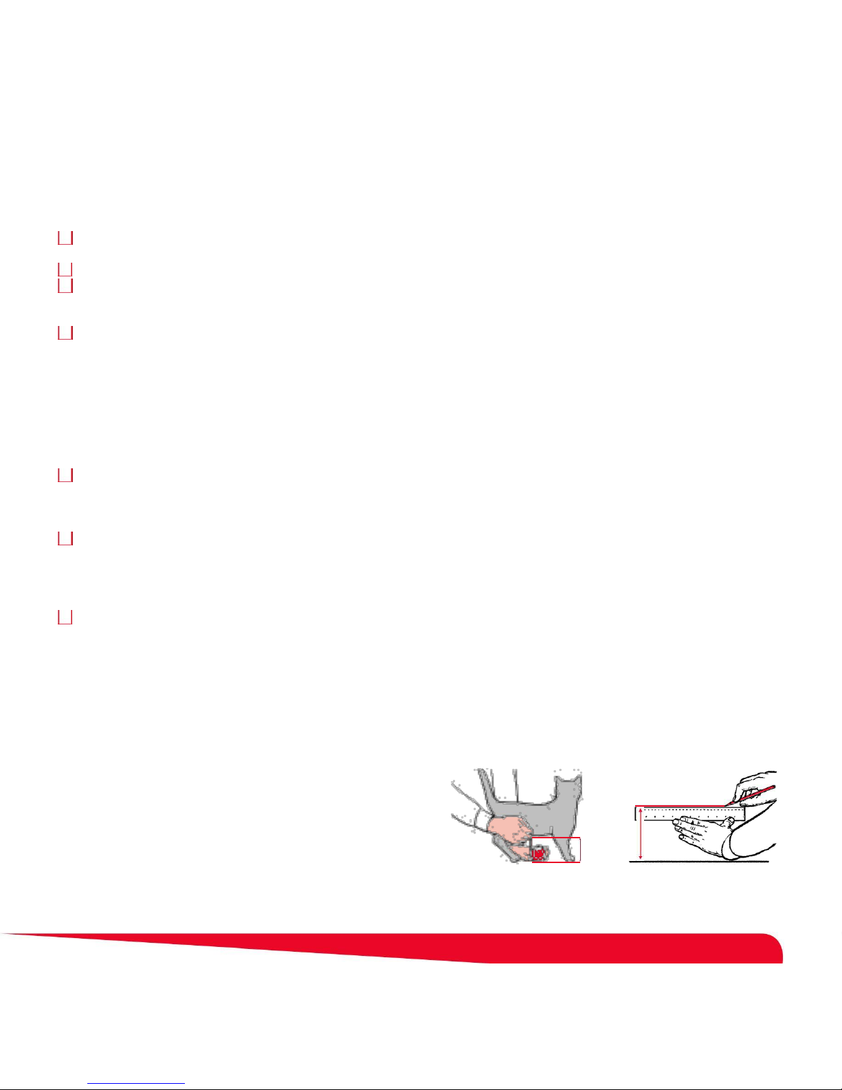
Liste de contrôle pour toutes les installations :
Avant de positionner le Petporte smart fl ap®, il est important de prendre en compte les points suivants.
Pour une installation dans une porte : est-ce que l'un ou l'autre des composants de la chatière Petporte smart fl ap® sera
bloqué par l'ouverture et la fermeture de la porte ?
Pour une installation dans un mur : y a-t-il des objets tels qu'une porte qui risquent de s'ouvrir sur la chatière Petporte smart flap® une fois installée ?
Où se trouve la prise murale la plus proche ? Votre chatière Petporte smart fl ap® est livrée avec une alimentation électrique
basse tension et un câble électrique de 2,5 m. Si la prise murale la plus proche est située à plus de 2,2 mètres, vous aurez besoin
d'une rallonge. Veuillez consulter la section Accessoires pour des renseignements sur l'achat d'une rallonge de 5 mètres.
Fonctionnement sur batterie uniquement. Pour un fonctionnement fi able et rapide, nous recommandons l'utilisation de
l'alimentation externe incluse dans le Petporte smart fl ap®. Cependant, vous pouvez brancher une batterie de 9 volts PP3 en option afi
n que votre chat puisse utiliser la chatière même en cas de coupure de courant. Nous recommandons l'utilisation d'une batterie au
lithium non rechargeable afi n de donner une plus longue autonomie de batterie. Veuillez noter que certaines options ne sont pas
disponibles lorsque le Petporte smart flap® fonctionne sur batterie : le mode nocturne automatique et l'installation murale.
Lorsque le Petporte smart fl ap® est alimenté par la source électrique externe, le scanner scanne en permanence la micropuce
de votre chat, et par conséquent, il enregistre normalement et déverrouille le volet avant que le chat arrive à la porte
transparente. Lorsque l'appareil fonctionne sur batterie, le chat devra pousser le volet transparent pour activer le scanner de
micropuce. Si votre chat ne fait que s'asseoir à l'extérieur du volet, il n'active pas le scanner et ne peut pas entrer.
Extensions de tunnel pour les portes et les murs d'une épaisseur supérieure à 52 mm. Veuillez noter que le Petporte smart fl ap® est
fourni avec une extension de tunnel pour les portes d'une épaisseur supérieure à 52 mm. Si votre installation nécessite un tunnel plus long, il
existe des sections de tunnel en option, fournissant chacune une longueur supplémentaire de 40 mm. Veuillez consulter la section Accessoires
pour des renseignements sur l'achat d'extensions de tunnel en option. Les tunnels peuvent être empilés par collage et emboîtage.
Y a-t-il une marche importante devant votre porte ? La hauteur de la chatière est idéale lorsque la base de l'appareil est à
la même hauteur que l'estomac de votre chat. Cependant, en raison des constructions de portes, il n'est pas toujours possible
d'installer une chatière si bas, et dans ce cas, il est recommandé d'installer le Petporte smart fl ap® aussi bas que possible sur
la porte. Le cas échéant, une petite marche peut être installée qui permettra de réduire la distance entre le porche à scanner
et la micropuce du chat (mais il ne faut pas qu'elle entraîne des risques de chute pour les gens).
Si votre porte possède déjà une ouverture, fait-elle plus de 212 mm de diamètre (circulaire) ou 171 mm de largeur x 180 mm de
hauteur ? Si l’ouverture de votre porte ou de votre mur est supérieure à ces dimensions, elle peut accueillir l’unité Petporte
smart fl ap®, car les plaques de protection intérieure et extérieure la cachent. Si l’ouverture est plus grande que les plaques de
protection intérieure et extérieure, l’unité Petporte smart fl ap®, peut être ajustée en remplaçant le panneau de porte ou en
créant des panneaux couvrant l’ouverture existante afi n de pouvoir couper une ouverture plus petite.
_______________________________________________________________________________________
Mesure et marquage
Fig. A
Fig. B
Mesurez la hauteur de votre chat au niveau du ventre. Elle est en
général comprise entre 100 et 150 mm (Figure A).
Marquez cette hauteur sur l'extérieur de votre porte et tracez une ligne
horizontale de 171 mm (Figure B).
Gardez à l’esprit que cette ligne correspondra en fait à la limite
X
inférieure du trou que vous allez découper dans la porte et que
(x)
l’encadrement de la chatière sera situé légèrement plus bas. En cas
de besoin, il est peut-être nécessaire de tracer la ligne plus haut en
prenant en compte l’encadrement.
27
Page 28

Installation du Petporte smart flap® dans une porte non vitrée
1. Fixer à l'extérieur de votre porte le modèle de découpe fourni, dans la position sélectionnée, en s'assurant qu'il est à l'endroit et horizontal.
2. Percer deux trous dans la porte de la maison avec un foret de 7 mm, comme indiqué sur le modèle de découpe.
3. Découper le grand trou comme indiqué par la ligne en pointillé sur le modèle de porte. Lors de cette découpe, ne pas s'écarter
de l'extérieur de la ligne en pointillé pour laisser suffi samment de place pour le tunnel.
4. Nettoyer la poussière, la saleté ou les débris dans la zone.
Remarque : suivre les étapes 5 à 9, si vous avez terminé les instructions d'assemblage (pour un test) en page 26.
5. Si l'alimentation électrique basse tension est branchée sur le secteur, la débrancher.
6. Retirer les 4 vis autotaraudeuses intérieures, le grand cache intérieur et la porte transparente.
7. Retirer les deux grandes vis M6 qui maintiennent les sections intérieure et extérieure ensemble.
8. Retirer la batterie si elle est connectée.
9. Déconnecter du circuit électronique le connecteur du câble du porche.
10. Monter la section intérieure à travers l'ouverture avec les sections de tunnel supplémentaires, selon les besoins. (voir la fi gure 11)
11. Faire passer le fi l à partir du porche et de la section extérieure à travers la porte et dans l'ouverture rectangulaire de la section
intérieure. Monter la section extérieure sur l'extérieur de la porte au dessus du tunnel.
12. Insérer les vis grandes M6 fournies dans la section extérieure et les visser dans la section intérieure. Veuillez noter que
selon l'épaisseur de votre porte, vous devrez peut-être découper la longueur des vis.
13. Enfoncer le connecteur sur le circuit électronique. Faire passer tout excès de câble à droite du compartiment de la batterie.
S'assurer que le câble ne se pose pas sur le circuit électronique. (voir la fi gure 12a et 12b)
14. Si une rallonge est nécessaire, la connecter au circuit électronique plutôt que sur l'alimentation. L'alimentation fournie se
connecte ensuite à la rallonge.
15. Si une rallonge n'est pas nécessaire, connecter le câble d'alimentation au connecteur électrique du circuit électronique. Faire
passer le câble le long des guides du câble de façon à ce que le fi l passe à travers l'une des fentes situées au bas de la
chatière, au plus près de la source d'alimentation.
16. Remettre en place la porte transparente en s'assurant que le rebord de la porte est tourné vers l'intérieur.
17. Refi xer le grand cache intérieur à l'aide des quatre vis autotaraudeuses.
18. Si une batterie est utilisée comme alternative à la source d'alimentation ou en plus de celle-ci, connecter une batterie PP3 de 9 volts et l'insérer
dans le compartiment de la batterie dans la section intérieure. Encliqueter le petit cache au dessus du compartiment de la batterie.
19. Lorsque l'installation du Petporte smart fl ap® est terminée, placer les deux bouchons d'obturation sur les vis du cadre
extérieur et les quatre bouchons d'obturation sur le cadre intérieur. (Figure 13)
20. Si vous avez choisi de ne pas utiliser le Petporte smart fl ap® uniquement sur batterie, branchez l'alimentation. Votre
chatière Petporte smart fl ap® est maintenant prête à l’emploi.
_______________________________________________________________________________________
Installation du Petporte smart flap® dans une porte ou fenêtre en verre
Le Petporte smart fl ap® est également conçu pour une installation dans du verre et nécessite une ouverture circulaire de 212 mm
de diamètre. Le travail du verre demande des compétences particulières et doit être réalisé par un vitrier professionnel. Votre
vitrier devra découper un trou circulaire de 212 mm de diamètre, selon le modèle de découpe du verre. Si vous avez le moindre
doute, veuillez consulter votre vitrier à propos de l'ajustement du Petporte smart fl ap®. Lorsqu'une ouverture adaptée est formée,
installer la chatière comme décrit pour une porte non vitrée, en commençant par l'étape 5.
Remarque : Deux petites vis (M6) sont inclus.
28
Page 29
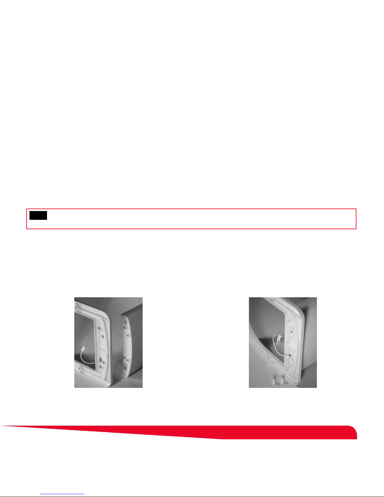
Installation du Petporte smart flap® dans un mur
Nous ne fournissons pas de vis de fi xation murale étant donné que le type de vis nécessaire dépend de la construction du mur.
Vous trouverez divers types de fi xations dans un magasin de bricolage : boulons et écrous à fi xation chimique, vis fi xées dans
des chevilles en plastique, vis autoperceuse en nylon, etc.
1. Le mur doit être ouvert à la hauteur et à la taille appropriées pour que votre chat puisse être scanné, sur base du modèle de découpe
fourni. L'ouverture murale doit être réalisée par un professionnel du bâtiment pour éviter les gaines électriques et la plomberie, et pour
ne pas endommager l'intégrité de l'isolation des murs contre l'humidité. La différence principale entre le Petporte smart fl ap® installé
sur un mur ou sur une porte réside dans la méthode de fi xation des sections intérieure et extérieure au mur.
2. Pour fi xer la section intérieure au mur, utiliser les quatre trous de 5 mm de diamètre dans les coins de la section intérieure et
accessibles une fois que le grand cache intérieur est retiré.
3. Pour fixer la section extérieure au mur, utiliser les deux trous de 6 mm de diamètre dans les côtés de la section extérieure qui soutiennent le
porche. Le Petporte smart fl ap® est équipé d'une seule extension de tunnel d'une longueur de 52 mm. Des extensions de tunnel peuvent
être achetées, chaque section supplémentaire permettant d'ajouter 40 mm. Ces éléments ne sont pas fournis avec le Petporte
smart fl ap® étant donné que l'épaisseur varie d'un mur à l'autre. Certains clients préfèrent confectionner leur propre tunnel en
utilisant du contreplaqué marine ou d'autres matériaux.
Veuillez consulter la section Accessoires de ce guide pour des renseignements sur l'achat d'extensions de tunnel en option.
Nous rejetons toute responsabilité en cas de fonctionnement incorrect de l'appareil si des modifi cations ont été apportées à la
bobine d'antenne. L'enroulement de la bobine d'antenne ne doit dans aucune circonstance être modifi é ou ajusté.
_______________________________________________________________________________________
Instructions d'assemblage
Fig. 1 Fig. 2
Faire passer le câble du porche
provenant du porche à travers
l'ouverture rectangulaire de la
section intérieure.
Insérer les quatre broches aplaties
dans le porche en passant à travers
le dos de la section extérieure.
29
Page 30
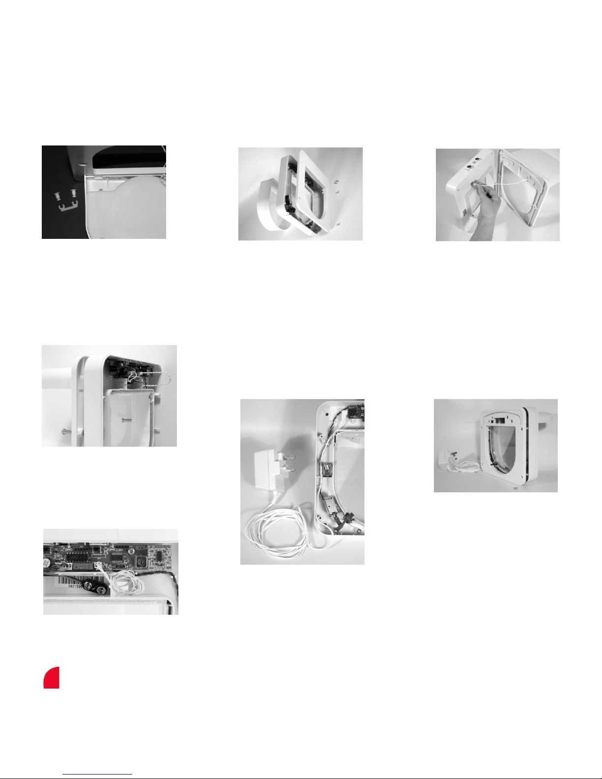
Fig. 3 Fig. 4 Fig. 5
Fixation des attaches "en fer à
cheval" sur les quatre broches
aplaties de la base du porche.
Fig. 6a
Retirer l'extension de tunnel
de la section intérieure.
Desserrer et retirer les quatre
vis autotaraudeuses de la
section intérieure et retirer le
grand cache intérieur.
Faire passer le câble du porche
provenant du porche et de la
section extérieure à travers
l'ouverture rectangulaire de la
section intérieure.
Fig. 7 Fig. 8
Assembler temporairement le
porche et la section extérieure à
la section intérieure à l'aide des
deux vis grande M6.
Fig. 6b
Fixer le câble du porche à la carte
électronique comme indiqué. Faire
passer tout excès de câble à droite
du compartiment de la batterie.
Fixer le connecteur
d'alimentation électrique basse
tension à la carte électronique
et faire passer le câble
d'alimentation à travers les
attaches, puis le faire sortir par
l'ouverture au bas de la
section intérieure.
Replacer le grand cache dans
la section intérieure, remettre
les quatre vis autotaraudeuses
et les serrer temporairement.
30
Page 31

Fig. 9 Fig. 10a Fig. 10b
Encliqueter le petit cache sur la
section intérieure.
Fig. 11
Mettre le Petporte smart fl ap® en
marche; programmer votre chat
comme indiqué en page 26 et
faire passer le Petporte smart fl
ap® au-dessus de votre chat, à la
distance à laquelle votre chat
s'approcherait normalement, pour
vérifi er que l'appareil fonctionne
avec votre chat.
Fig. 12a
Fig. 12b
Vous pouvez également tenir
le Petporte smart fl ap® à
l'envers pour programmer la
micropuce de votre chat.
Fig. 13
Lorsque vous installez le
Petporte smart fl ap® dans une
ouverture, mettre la section
intérieure avec des extensions
de tunnel, si besoin, à la hauteur
de l'ouverture. Ensuite, faire
passer le câble du scanner
provenant du porche et de la
section extérieure à travers
l'ouverture rectangulaire de la
section intérieure.
Fixer le câble du porche à la carte
électronique et maintenir les
sections intérieure et extérieure
ensemble à l’aide des deux vis
grandes M6. Serrer les vis pour fi
xer le Petporte smart
fl ap® dans la position souhaitée
à l’intérieur de l’ouverture.
Une fois positionné, fi xer le grand cache
et bien l'attacher avec les quatre vis
autotaraudeuses. Encliqueter le petit
cache. Placer tous les bouchons
d'obturation, les quatre petits pour les
vis autotaraudeuses et les deux grands
pour les vis grandes M6. Enfi n, mettre
votre Petporte smart fl ap® en marche.
31
Page 32

Guide rapide du Petporte smart flap®
Fonction
Activation du bouton
Fonction du bouton de mode
Mode normal
C'est le mode par défaut au démarrage
et il ne nécessite aucune activation de
bouton.
Mode nocturne (Mode horloge)
Appuyer sur le bouton rouge pendant
Le voyant rouge s’allume.
(non disponible en mode batterie)
moins de 2 secondes
En Mode nocturne : pendant les heures
sombres, le voyant vert est allumé et
l’unité empêche automatiquement le chat
de sortir. Il s’éteint à l’aube ; le verrou
s’ouvre et le chat peut sortir jusqu’au
crépuscule.
En Mode horloge : l’unité se verrouille et
se déverrouille aux heures programmées
de la journée.
Mode vétérinaire
Appuyer sur le bouton rouge pendant
Le voyant rouge clignote et l'appareil ne
plus de 2 secondes
permet pas aux chats de sortir.
Saisie du programme
Maintenir le bouton vert enfoncé pendant
Le voyant vert clignote et vous avez alors
plus de 10 secondes
30 secondes pour programmer votre chat
en faisant passer l'animal sous le porche.
Modes étendus
Maintenir le bouton vert et le bouton
L'appareil émet un long bip qui indique
rouge enfoncés pendant plus de 2
que les modes étendus sont disponibles
secondes
et le voyant vert s'allume. (Voir les Modes
étendus - Guide rapide en page 33.)
Verrouillage de clavier
Maintenir le bouton rouge enfoncé
L'appareil émet une série de bips
pendant plus de 30 secondes
indiquant qu'elle est verrouillée.
Mode effacement
Maintenir le bouton vert et le bouton
L'appareil émet une série de bips courts
rouge enfoncés pendant plus de 30
suivis d'un bip long. Les deux voyants
secondes
doivent clignoter.
Remarque : une fois que la mémoire est
effacée, il faut reprogrammer l’appareil
avant utilisation !
Reset au Mode normal
Maintenir le bouton vert enfoncé pendant
L'appareil émet une série de bips courts
plus de 30 secondes
suivis d'un bip long. Les deux voyants
doivent s'éteindre. Maintenir les deux
boutons enfoncés simultanément
pendant plus de 30 secondes et DES LE
RELACHEMENT, l'appareil émet un long
bip.
32
Page 33

Modes étendus - Guide rapide
Veuillez consulter en page 35 l'explication complète de chaque Mode étendu.
Maintenir les boutons rouge et vert enfoncés simultanément pendant plus de 2 secondes, puis les relâcher pour entrer dans le
menu du Mode étendu.
Dans les Modes étendus, le voyant vert s'allume et vous commencez en Mode sortie. Les modes sont sélectionnés en appuyant sur le
bouton rouge pour "monter" d'un mode et sur le bouton vert pour "descendre" d'un mode. Le mode courant est indiqué par le nombre de
bips. Lorsque vous êtes dans le mode souhaité, appuyez rapidement sur les deux boutons simultanément pour activer ce mode.
Nombre de bips
Mode
Fonction
1
Mode sortie
Annule l'option de mode étendu et rétablit le Petporte smart fl ap® en mode
de fonctionnement normal.
2
Mode ouverture
Le voyant vert clignote et la fermeture verte s'abaisse, permettant à tout chat
de passer dans le Petporte smart fl ap®.
3
Mode silencieux
L'avertissement sonore n'est pas émis lorsque votre chat est reconnu par le
Petporte smart fl ap®.
4
Mode défi nition du niveau de
Défi nit le niveau de lumière souhaité pour lequel la chatière se verrouille et
lumière
se déverrouille pendant le mode de fonctionnement nocturne.
5
Temps de verrouillage
Le temps par défaut pour que les fermetures de votre Petporte smart
fl ap® reviennent en position verrouillée après la reconnaissance de la
micropuce de votre chat est de 4 secondes. Cependant, si votre chat est
particulièrement craintif, ou s’il est fréquemment poursuivi par d’autres
chats, vous pouvez allonger ou raccourcir le temps de rétablissement du
verrouillage.
6
Verrouillage pour batterie
Lorsque le Petporte smart fl ap® fonctionne sur batterie, si la batterie se
faible
décharge, le Petporte smart fl ap® comporte une option intégrée qui permet
de défi nir la position des fermetures, ouverte ou fermée.
7
Mode horloge
Défi nit les heures de la journée auxquelles la chatière se verrouille et se
déverrouille lorsqu’elle fonctionne en Mode nocturne.
33
Page 34

Modes de fonctionnement
Mode normal
C'est le mode par défaut lors de la mise sous tension de la chatière, et il permet uniquement le passage de votre/vos chat(s).
Mode nocturne
Pour diverses raisons, de nombreux propriétaires d’animaux préfèrent qu’ils ne sortent pas la nuit. L’unité Petporte smart fl ap®
dispose d’un mode empêchant automatiquement votre animal de sortir la nuit et déverrouillant automatiquement la chatière à
l’aube. Si votre animal est encore dehors à la tombée de la nuit, le système lui permet tout de même d’entrer.
Le Mode nocturne permet également aux propriétaires d’animaux de régler l’heure du jour où ils veulent que l’unité se verrouille
et se déverrouille (Mode horloge).
Pour employer ce mode, appuyez sur le bouton rouge moins de 2 secondes. L’unité émet un bip et le voyant rouge s’allume pour
vous informer qu’elle est en Mode nocturne (Mode horloge).
• À l’heure de VERROUILLAGE prédéfinie ou à la tombée de la nuit, le voyant vert s’allume pour indiquer que la chatière est verrouillée.
• À l’heure de DÉVERROUILLAGE prédéfinie ou à la lueur du jour, le voyant vert s’éteint pour indiquer que la chatière est déverrouillée.
Remarque : Il peut falloir jusqu’à 30 secondes pour que le Mode nocturne commence à fonctionner.
Mode vétérinaire
Si vous avez l'intention d'amener votre animal chez le vétérinaire, ou si vous voulez juste qu'il reste à l'intérieur, la chatière
Petporte smart fl ap® propose un mode qui laisse votre animal entrer mais ne le laisse plus sortir.
Pour activer ce mode, appuyer sur le bouton rouge pendant 5 secondes ou jusqu'à ce que le voyant rouge commence à clignoter et
le relâcher. L'appareil émet un bip et le voyant rouge commence à clignoter, indiquant que la chatière est verrouillée et que le chat
ne peut pas sortir.
Pour sortir de ce mode, appuyer à nouveau sur le bouton rouge pendant 5 secondes ou jusqu'à ce que le voyant rouge
commence à clignoter et le relâcher. L'appareil émet à nouveau un bip et le voyant rouge s'éteint.
Mode étendu
Le Petporte smart fl ap® comporte plusieurs modes étendus qui vous permettent de personnaliser votre chatière Petporte smart
fl ap® selon vos besoins.
Pour des renseignements sur l'utilisation des modes étendus, veuillez consulter la section Modes étendus en page 35 de ce guide.
Verrouillage de clavier
Si vous souhaitez verrouiller les boutons de votre Petporte smart fl ap® (ceci est utile pour empêcher les enfants de dérégler les
modes), maintenir le bouton rouge enfoncé pendant 30 secondes. L'appareil doit émettre des bips à plusieurs reprises. Relâcher le
bouton rouge et l'appareil sera réglé sur le verrouillage du clavier.
Pour réactiver la commande des boutons et désactiver le verrouillage du clavier, répéter le processus ci-dessus.
Mode effacement
Si vous souhaitez effacer tous les numéros d'identifi cation d'animaux programmés dans la mémoire de votre système, veuillez
employer la procédure suivante. Il faut cependant noter qu'une fois que la mémoire est effacée, il faut reprogrammer l'appareil
avec les animaux qui vont utiliser la chatière. Par conséquent, veuillez vous assurer que vous souhaitez réellement effacer la
mémoire avant de continuer.
Pour effacer tous les numéros de micropuces, maintenir les boutons rouge et vert enfoncés pendant 30 secondes. L'appareil doit
émettre des bips à plusieurs reprises. Relâcher les boutons rouge et vert ; l'appareil doit émettre un long bip et les deux voyants
doivent clignoter, indiquant que la mémoire a été effacée.
Remarque : une fois que la mémoire est effacée, il faut reprogrammer l'appareil avant utilisation !
Reset au Mode normal
Si vous souhaitez réinitialiser votre Petporte smart fl ap® et le rétablir en mode normal et en modes de sortie tels que le mode
nocturne, le mode vétérinaire ou le mode ouverture, veuillez employer la procédure suivante.
Maintenir le bouton vert enfoncé pendant plus de 30 secondes ou jusqu'à ce que l'appareil émette une série de bips courts, avant
de relâcher le bouton. L'appareil doit émettre un long bip et les deux voyants doivent s'éteindre, indiquant que le Petporte smart fl
ap® est en mode de fonctionnement normal. Le rétablissement en Mode normal n'efface pas les numéros de micropuce
programmés ni les différentes fonctions disponibles en modes étendus.
34
Page 35

Modes étendus
Les modes étendus du Petporte smart fl ap® vous donnent la possibilité de personnaliser le Petporte smart fl ap® selon vos
besoins. Pour activer le menu des modes étendus, maintenir les boutons rouge et vert enfoncés simultanément pendant 2
secondes, ou jusqu'à ce que les deux voyants commencent à clignoter, puis les relâcher. Le Petporte smart fl ap® doit émettre un
bit et le voyant vert s'allumer pour vous informer que vous êtes entré dans la première des options de menu du mode étendu.
En "mode étendu', les modes sont sélectionnés en appuyant sur le bouton rouge pour "monter" d'un mode et sur le bouton vert
pour "descendre" d'un mode. Le mode courant est indiqué par le nombre de bips. Lorsque vous êtes dans le mode souhaité,
appuyez rapidement sur les deux boutons simultanément pour activer ce mode. Consulter le tableau des modes étendus
disponibles en page 33. Si aucun bouton n'est enfoncé pendant 20 secondes, le Petporte smart fl ap® émet un bip et le voyant
vert s'éteint, indiquant que l'appareil revient en mode de fonctionnement normal.
Mode sortie (quitter les modes étendus) - 1 bip
C'est le premier mode dans le menu des modes étendus. Il est indiqué par un bip unique. Cette option annule simplement le
"mode étendu" et rétablit le Petporte smart fl ap® en mode de fonctionnement normal. Pour activer le mode sortie, appuyer
rapidement sur les deux boutons rouge et vert simultanément.
Mode ouverture - 2 bips
Dans le cas improbable où vous souhaiteriez que le Petporte smart fl ap® s'ouvre pour donner l'accès à n'importe quel animal, le
Petporte smart fl ap® propose un mode dans lequel tout animal (avec ou sans micropuce) peut passer dans la chatière. Activer
les modes étendus en appuyant simultanément sur les boutons rouge et vert pendant plus de 2 secondes, puis appuyer une fois
sur le bouton rouge pour activer le mode ouverture qui sera indiqué par 2 bips. Ensuite, pour activer le mode ouverture et sortir
des modes étendus, appuyer rapidement sur les boutons rouge et vert simultanément.
Lorsque le mode ouverture est activé, l'appareil émet un long bip et le voyant vert doit clignoter pour montrer que l'appareil est
en mode ouverture.
Pour désactiver le mode ouverture, activez encore une fois le mode ouverture. L'appareil émet à nouveau un long bip et le voyant
vert doit s'éteindre, indiquant que le Petporte smart fl ap® est retourné en mode de fonctionnement normal.
Mode silencieux - 3 bips
Chaque fois qu'un animal reconnu entre ou sort par le Petporte smart fl ap®, l'appareil émet un bip court. Pour supprimer ce bip, activer le
mode silencieux. Activer les modes étendus en appuyant simultanément sur les boutons rouge et vert pendant plus de 2 secondes, puis
appuyer une fois sur le bouton rouge (l'appareil va émettre 2 bips), puis une autre fois pour activer le mode silencieux qui sera indiqué par
3 bips. Ensuite, pour activer le mode silencieux et sortir des modes étendus, appuyer rapidement sur les boutons simultanément. Un bip
court va être émis, puis aucun bip lorsque votre animal entre ou sort par le Petporte smart fl ap®.
Pour réentendre les bips, activer le mode silencieux une fois encore. L'appareil émet à nouveau un bip court, suivi par un bip
court chaque fois que votre animal entre ou sort par le Petporte smart fl ap®.
Mode définition du niveau de lumière - 4 bips
Lorsque le Petporte smart fl ap® est réglé sur le mode nocturne, le capteur de lumière détecte un niveau prédéfi ni de lumière
ambiante et verrouille ou déverrouille la chatière en fonction.
Si vous souhaitez modifi er le moment où votre Petporte smart fl ap® se verrouille ou déverrouille en mode nocturne, activez simplement le
Mode défi nition du niveau de lumière, le matin ou le soir, lorsque la lumière extérieure est suffi sante pour que votre chat soit en sécurité
dehors. Assurez-vous que vos lumières d'intérieur sont éteintes lorsque vous redéfi nissez le niveau de lumière ; sinon, cela peut infl
uencer le capteur de lumière. Activer les modes étendus en appuyant simultanément sur les boutons rouge et vert pendant plus de 2
secondes, puis appuyer une fois sur le bouton rouge (l'appareil va émettre 2 bips), puis une autre fois sur ce bouton rouge (l'appareil va
émettre 3 bips), puis appuyer encore une fois sur ce bouton rouge et l'appareil va émettre 4 bips alors que vous entrez dans le Mode défi
nition du niveau de lumière. Pour sélectionner l’intensité lumineuse à laquelle vous voulez verrouiller ou déverrouiller la porte, appuyez
simultanément sur les boutons rouge et vert. L’unité émet un bip et quitte les modes étendus.
Vous devez maintenant activer le Mode nocturne pour que l’unité détecte les intensités lumineuses programmées et
verrouille ou déverrouille la porte en conséquence. Pour ce faire, appuyez sur le bouton rouge moins de 2 secondes.
35
Page 36

Remarque : le niveau de lumière défi ni reste en mémoire même si l'alimentation du Petporte smart fl ap® est coupée. Le
capteur de lumière sera affecté par les lumières de l'intérieur, les lumières de secours ou celles de la rue.
Temps de verrouillage - 5 bips
Le temps par défaut pour que les fermetures de votre Petporte smart fl ap® reviennent en position verrouillée après la
reconnaissance de la micropuce de votre chat est de 4 secondes. Cependant, si votre chat est particulièrement craintif, ou s'il est
fréquemment poursuivi par d'autres chats, vous pouvez allonger ou raccourcir le temps de rétablissement du verrouillage à l'aide
de la procédure suivante.
Activer les modes étendus en appuyant simultanément sur les boutons rouge et vert pendant plus de 2 secondes, puis appuyer une fois
sur le bouton rouge (l'appareil va émettre 2 bips), puis une autre fois (l'appareil va émettre 3 bips), puis une autre fois (l'appareil va
émettre 4 bips), et encore une fois et l'appareil va émettre 5 bips alors que vous entrez dans le Mode Temps de verrouillage. Pour activer
le Mode Temps de verrouillage, appuyer simultanément sur les deux boutons, le voyant vert reste allumé et le voyant rouge clignote.
Maintenir le bouton vert enfoncé pendant le temps de verrouillage souhaité, compris entre 1 et 25 secondes, avant de le relâcher.
Pendant ce temps, un bip sonore est émis pendant toute la durée où le bouton vert est enfoncé, jusqu'à ce qu'il soit relâché. Lorsque le
bouton vert est relâché, le Petporte smart fl ap® retourne à son mode de fonctionnement normal.
Verrouillage pour batterie faible - 6 bips
Lorsque le Petporte smart fl ap® fonctionne sur batterie, si la batterie se décharge, le Petporte smart fl ap® comporte une option
intégrée qui permet de défi nir la position des fermetures, ouverte ou fermée.
Cette option permet, par exemple, d'ouvrir ou de fermer la fermeture verte lorsque la batterie est faible, pour permettre ou
empêcher à l'animal de passer par le Petporte smart fl ap® et d'entrer dans la maison. De la même manière, on peut ouvrir ou
fermer la fermeture rouge lorsque la batterie est faible, pour permettre ou empêcher à l'animal de passer par le Petporte smart fl
ap® et sortir de la maison. Activer les modes étendus en appuyant simultanément sur les boutons rouge et vert pendant plus de 2
secondes, puis appuyer une fois sur le bouton rouge (l'appareil va émettre 2 bips), puis une autre fois (l'appareil va émettre 3 bips),
puis une autre fois (l'appareil va émettre 4 bips), puis une autre fois (l'appareil va émettre 5 bips), et encore une fois et l'appareil va
émettre 6 bips alors que vous entrez dans le Mode Verrouillage pour batterie faible. Pour activer le Mode Verrouillage pour batterie
faible, appuyer sur les boutons rouge et vert simultanément, le voyant vert reste allumé et l'appareil émet un bip.
La pression du bouton vert fait basculer la fermeture verte entre ouverte et fermée, alors que la pression du bouton rouge fait
basculer la fermeture rouge entre ouverte et fermée.
Lorsque les fermetures rouge et verte sont dans la position souhaitée, une pression rapide et simultanée des boutons rouge et vert
entraine l'émission d'un bip court et le Petporte smart fl ap® sort des modes étendus et revient en mode de fonctionnement normal.
Mode horloge - 7 bips
Lorsque l’unité Petporte smart fl ap® est en Mode nocturne, vous pouvez aussi déterminer l’heure de la journée à laquelle vous
voulez que la chatière se verrouille ou se déverrouille en utilisant le Mode horloge. Ce mode est une alternative au « Mode de
réglage de l’intensité lumineuse », qui dépend de la luminosité ambiante autour de la porte.
Pour régler l’heure de DÉVERROUILLAGE : cette fonction doit être activée à l’heure de la journée où vous voulez que l’unité
s’OUVRE et reste DÉVERROUILLÉE.
Entrez en Modes étendus en appuyant simultanément sur les boutons rouge et vert pendant plus de 2 secondes. Ensuite, appuyez
sur le bouton rouge une fois (l’unité émet deux bips), puis une deuxième fois (l’unité émet trois bips), une troisième (l’unité émet
quatre bips), une quatrième (l’unité émet cinq bips), une cinquième (l’unité émet six bips), puis une dernière fois pour que l’unité
émette 7 bips ; vous êtes alors en Mode horloge. Pour entrer dans ce mode, appuyez simultanément sur les boutons rouge et vert.
Le voyant vert reste allumé, alors que le rouge clignote.
Pour régler l’heure de DÉVERROUILLAGE, appuyez et relâchez rapidement le bouton vert. L’unité Petporte smart fl ap® revient
alors en mode de fonctionnement normal.
Pour régler l’heure de VERROUILLAGE : cette fonction doit être activée à l’heure de la journée où vous voulez que l’unité se
FERME et reste VERROUILLÉE.
Entrez en Modes étendus en appuyant simultanément sur les boutons rouge et vert pendant plus de 2 secondes. Ensuite, appuyez sur
36
Page 37

le bouton rouge une fois (l’unité émet deux bips), puis une deuxième fois (l’unité émet trois bips), une troisième (l’unité émet
quatre bips), une quatrième (l’unité émet cinq bips), une cinquième (l’unité émet six bips), puis une dernière fois pour que l’unité
émette 7 bips ; vous êtes alors en Mode horloge. Pour entrer dans ce mode, appuyez simultanément sur les boutons rouge et
vert. Le voyant vert reste allumé, alors que le rouge clignote.
Pour régler l’heure de VERROUILLAGE, appuyez et relâchez rapidement le bouton rouge. L’unité Petporte smart fl ap® revient
alors en mode de fonctionnement normal.
Vous devez maintenant activer le Mode nocturne pour que l’unité détecte les heures de VERROUILLAGE et de
DÉVERROUILLAGE programmées. Pour ce faire, appuyez sur le bouton rouge moins de 2 secondes.
Remarque :
1. Le Mode horloge fonctionne uniquement lorsque l’unité est mise sous tension par le biais de l’alimentation externe jointe à
l’unité. Il n’est pas disponible lorsque l’unité entre en mode de sauvegarde de batterie.
2. En cas de coupure de courant, vous devrez réinitialiser les heures de verrouillage et de déverrouillage.
3. Le Mode horloge a la priorité sur le détecteur d’intensité lumineuse. Dans ce cas, l’unité ne mesure plus les intensités
lumineuses ambiantes pour déterminer si l’unité doit être verrouillée ou déverrouillée.
Voyant DEL - Guide rapide
Explication des voyants DEL :
Fonction
Clignotement
Clignotement
Sous tension mais rien n'est programmé
Éteint
Éteint
Mode de fonctionnement normal
Éteint (le jour) / allumé (la nuit)
Allumé
Mode nocturne (Mode horloge)
Éteint
Clignotement
Mode vétérinaire
Clignotement
Éteint
Mode ouverture
Allumé
Clignotement
Niveau de batterie faible
Option de batterie de secours
Votre Petporte smart fl ap® comporte une option pour installer une batterie de secours, afi n de garantir que votre chat puisse
toujours avoir accès à votre maison en cas de coupure de courant au niveau de l'alimentation basse tension.
Pour installer les batteries, retirer le petit cache avec un tournevis et fi xer une batterie PP3 de 9 volts sur les connections. Insérer
la batterie dans le compartiment de la batterie et remettre le petit cache en position.
Veuillez noter que les fonctions suivantes ne sont pas actuellement disponibles avec votre Petporte smart fl ap®, lorsque
l'appareil fonctionne sur batterie uniquement :
1. Montage mural - Actuellement, l'option de batterie de secours du Petporte smart fl ap® ne peut pas fonctionner sur un appareil mural.
2. Mode nocturne - Actuellement, le mode nocturne n'est pas disponible lorsque l'appareil entre en mode batterie de secours.
37
Page 38

Pour entraîner votre chat à utiliser la chatière
La plupart des animaux apprennent à utiliser la chatière presque immédiatement, mais certains peuvent être nerveux au début. Les
conseils suivants aideront votre animal à profi ter de sa liberté à se rendre dehors et du confort de votre maison, une souplesse que
vous voulez offrir à votre animal et que votre nouvelle chatière vous apporte.
La règle d’or consiste à se montrer patient avec votre animal. Ne soyez pas pressé. Laissez à votre animal le temps de
comprendre qu’il peut entrer et sortir. Ne le forcez pas à passer par la trappe car cela risque de l’effrayer.
De nombreux propriétaires d’animaux installent une chatière lorsqu’ils déménagent. Si c’est votre cas, assurez-vous que votre
animal a eu le temps de se familiariser avec son nouvel environnement avant de mettre la chatière en place. Amenez votre
animal dehors en le surveillant et en le gardant en laisse, et assurez-vous qu’il se sent également en sécurité et à l’aise dans sa
nouvelle maison. Les chats peuvent tout particulièrement développer des peurs à long terme dans un environnement étranger.
Une fois que vous avez installé la chatière, laissez la trappe ouverte pendant un certain temps. Pour ce faire, vous pouvez utiliser
une longue bande de ruban-cache; ouvrez la trappe et utilisez le ruban pour la maintenir ouverte en collant l’autre extrémité du
ruban à la surface au-dessus de la chatière. Assurez-vous que la trappe est bien attachée et qu’elle ne tombera pas
accidentellement. Laissez votre chat se familiariser avec la chatière en entrant et en sortant librement.
Encouragez votre chat à utiliser la chatière. La nourriture constitue une bonne motivation. Commencez par donner à manger au chat près de la
chatière à l’intérieur de la maison, et ensuite à l’extérieur près de la chatière. Recommencez aussi souvent que nécessaire. La plupart des
chats, particulièrement les chatons, ont un fort besoin de liberté, peut-être même de fortes envies de chasser. Ils sont également très sociables
et apprécient la compagnie des autres chats. C’est une autre bonne raison pour eux d’aller explorer ce qui se trouve à l’extérieur de la maison.
Certains chats auront cependant besoin de plus de temps pour faire confi ance au système et pour se familiariser avec le fonctionnement de la porte
du Petporte smart fl ap®. Servez-vous de la friandise préférée de votre chat pour l’encourager à entrer et à sortir par la chatière et pour le récompenser
lorsqu’il réussit. Une fois que votre chat est à l'aise pour passer dans la chatière, enlevez le ruban-cache et abaissez le volet.
Accessoires
Pour commander des accessoires supplémentaires pour votre Petporte smart fl ap®, visitez notre site www.petsafe.net pour
trouver un revendeur près de chez vous et pour consulter la liste des numéros de téléphone de notre Service clientèle.
PAC19-12596
Extension de tunnel - blanche
PAC19-12597
Extension de tunnel - marron
PAC19-12741
Volet de rechange
PAC19-12753
Rallonge de câble de 5 m - noire
PAC19-12598
Rallonge de câble de 5 m - blanche
MPA00-12867
Adaptateur - Royaume-Uni - blanc
MPA00-12868
Adaptateur - Europe - blanc
MPA00-12869
Adaptateur - Royaume-Uni - noir
MPA00-12870
Adaptateur - Europe - noir
MPA00-12766
Kit de matériel
Nettoyage de la chatière
Votre chatière a été fabriquée à partir des matériaux de la meilleure qualité et elle comporte une trappe renforcée; le tout a été conçu pour
durer de nombreuses années. Pour conserver son apparence, il vous suffi t de l’essuyer régulièrement à l’aide d’un chiffon humide.
Remarque : ne jamais utiliser de cire de ménage car cela peut endommager le produit.
Désactiver la chatière
Si vous ne souhaitez plus que l’appareil fonctionne, la procédure suivante vous permet de verrouiller la chatière et d’éteindre
complètement l’appareil. Si une batterie est installée dans l’appareil, la retirer. Placer l’appareil en mode de fonctionnement normal de
façon à ce que la fermeture verte soit vers le haut ; utiliser les modes étendus - fonction du mode sortie, si besoin. Ensuite, activer le
mode vétérinaire pour que la fermeture rouge soit vers le haut en appuyant sur le bouton rouge pendant 5 secondes. Enfi n, retirer
l’adaptateur et/ou les rallonges. Les deux fermetures restent vers le haut et maintiennent la chatière en position verrouillée.
38
Page 39

Élimination des batteries usagées
Le tri sélectif des piles usagées est obligatoire dans de nombreuses régions ; vérifi ez les règlements en vigueur dans votre
localité. Ce dispositif fonctionne avec une pile alcaline de 9 V (PP3/IEC 6LR61). Remplacer uniquement par une pile équivalente.
Pour retirer la batterie du dispositif, retirer le petit cache avec un tournevis et détacher la batterie des connections.
Conseil important concernant le recyclage
Veuillez respecter les réglementations concernant les déchets électriques et les déchets de matériel électrique en vigueur dans votre
pays. Ce dispositif doit être recyclé. Si vous n'avez plus l'utilité de ce matériel, ne le jetez pas avec vos déchets normaux. Veuillez
le rapporter chez votre revendeur pour que ce dispositif soit placé dans notre programme de recyclage. Si cela n'est pas
possible, veuillez contacter le Service clientèle pour plus d'informations.
Conformité
Par le présent document, Radio Systems® Corporation déclare que la chatière à micropuce Petporte smart fl ap® est conforme aux exigences essentielles
et autres dispositions pertinentes de la directive 1999/5/CE (R&TTE). Toute modifi cation du dispositif non autorisée par Radio Systems® Corporation
peut enfreindre la directive européenne, peut annuler la capacité de l'acheteur à utiliser le dispositif et annuler la garantie.
Vous pouvez trouver la déclaration de conformité sur le lien suivant : http://www.petsafe.net/customercare/eu_docs.php.
Australie
Ce système satisfait à la norme de compatibilité électromagnétique spécifi é par l'ACMA (Australian Communications and Media Authority).
_________________________________________________________________________________________________
Conditions d'utilisation et limite de responsabilité
1. Conditions d'utilisation
En achetant ce produit, vous acceptez les termes, conditions et consignes d'utilisation tels qu'ils sont stipulés dans ce manuel. L'utilisation de ce produit revient à en
accepter les termes, conditions et consignes d'utilisation. Si vous n'acceptez pas ces termes, conditions et consignes d'utilisation, veuillez renvoyer ce produit, inutilisé,
dans son emballage d'origine et à vos frais et risques, au Service clientèle approprié avec une preuve d'achat afin d'obtenir un remboursement complet.
2. Utilisation adéquate
Ce produit est conçu pour être utilisé avec des animaux pour lesquels un dressage est nécessaire. Le tempérament spécifique ou la taille/le poids
de votre animal peuvent ne pas convenir pour ce produit (veuillez consulter ce Manuel d’utilisation). Radio Systems® Corporation déconseille
l'utilisation de ce produit si votre animal est agressif et rejette toute responsabilité quant au caractère approprié du produit à un animal spécifique.
Si vous n'êtes pas sûr que ce dispositif soit approprié à votre animal, veuillez consulter votre vétérinaire ou un dresseur agréé avant de l'utiliser.
Une utilisation appropriée comprend, entre autres, la consultation de la totalité de ce manuel ainsi que de l'ensemble des avertissements.
3. Utilisation illégale ou interdite
Ce produit est conçu pour être utilisé exclusivement avec des animaux de compagnie. Ce dispositif de dressage n'est pas destiné à blesser ni à
provoquer un animal. L'utilisation inappropriée de ce produit peut représenter une violation des lois fédérales, nationales ou locales.
4. Limitation de responsabilité
Radio Systems® Corporation et ses sociétés affiliées ne peuvent en aucun cas être tenus responsables pour (i) des dommages directs, indirects, punitifs, accidentels,
spéciaux ou secondaires, (ii) ni pour des pertes ou dommages occasionnés ou associés à l'utilisation inappropriée de ce produit. L'acheteur prend à sa charge les
risques et les responsabilités en rapport avec l'utilisation de ce produit et dans la pleine mesure prévue par la loi. Dans le but d'éviter toute ambiguïté, aucune partie de
la clause 4 ne peut engager la responsabilité de Radio Systems® Corporation en cas de décès, de blessures corporelles, de fraude ou de fausse déclaration.
5. Modification des termes et des conditions
Radio Systems® Corporation se réserve le droit de modifier les termes, les conditions et les consignes d'utilisation applicables à ce produit. Si de telles modifications
vous ont été communiquées avant que vous n'utilisiez ce produit, elles ont une valeur contractuelle et s'appliquent comme si elles faisaient partie du présent document.
39
Page 40

Uitleg van in deze handleiding gebruikte belangrijke woorden en symbolen
Dit is het symbool voor een veiligheidswaarschuwing. Het wordt gebruikt om u te wijzen op
mogelijke risico's van persoonlijk letsel. Volg alle veiligheidsberichten op die volgen op dit symbool
om mogelijk letsel of overlijden te voorkomen.
WAARSCHUWING geeft een risicovolle situatie aan die, wanneer deze niet vermeden wordt, kan
leiden tot overlijden of ernstig letsel.
VOORZICHTIG, in combinatie met het symbool voor veiligheidsalarm, geeft een risicovolle situatie
aan die, wanneer deze niet vermeden wordt, kan leiden tot licht of matig letsel.
AANWIJZING wordt gebruikt om te wijzen op werkwijzen die niet gerelateerd zijn aan persoonlijk letsel.
_______________________________________________________________________________________
Wanneer er kinderen in het huis aanwezig zijn, is het belangrijk het huisdierenluik in overweging te nemen bij het
kinderveilig maken; het huisdierenluik kan door kinderen worden gebruikt, waardoor het kind toegang krijgt tot
risicovolle situaties die zich aan de andere kant van het huisdierenluik bevinden. Aankopers/Huiseigenaren met
een zwembad dienen ervoor te zorgen dat het huisdierenluik te allen tijde wordt bewaakt en dat het zwembad op
adequate wijze is afgesloten voor toegang. Als een nieuw risico binnen of buiten het huis ontstaat, waarbij het
huisdierenluik hiertoe toegang kan verschaffen, beveelt Radio Systems Corporation® aan dat de toegang tot dit risico
op juiste wijze wordt afgeschermd of dat het huisdierenluik wordt verwijderd. De afsluiting of vergrendeling, indien van
toepassing, wordt geleverd voor esthetische doelen en energiebesparing; deze is niet bedoeld als beveiligingsmiddel.
Radio Systems Corporation® zal niet aansprakelijk zijn voor onbedoeld gebruik en de koper van dit product accepteert
volledige verantwoordelijkheid voor supervisie over de gecreëerde toegang.
• Elektrisch gereedschap. Risico op ernstig letsel; volg alle veiligheidsinstructies voor het elektrische gereedschap.
• Zorg ervoor dat te allen tijde een veiligheidsbril gedragen wordt.
De gebruiker dient zich voor de installatie vertrouwd te maken met alle bouwvoorschriften die van invloed
kunnen zijn op de installatie van het huisdierenluik en, samen met een gekwalificeerd aannemer, vast te
stellen dat de gewenste installatie geschikt is. Dit huisdierenluik is geen branddeur. Het is belangrijk dat
eigenaar en aannemer alle risico's die zich binnen of buiten het huisdierenluik kunnen bevinden, in overweging
nemen; hierbij gaat het ook om risico's die kunnen ontstaan door latere wijzigingen aan het perceel en hoe
deze zich kunnen verhouden tot het bestaan en gebruik van het huisdierenluik, inclusief misbruik ervan.
• Bewaar deze instructies bij uw belangrijke papieren; zorg ervoor dat u deze instructies overdraagt aan
een nieuwe eigenaar van het perceel.
• Lees deze aanwijzingen in hun geheel door voor het creëren of wijzigen van een opening in de geselecteerde deur
of muur. Het wordt ten zeerste aanbevolen de Petporte smart flap® te monteren, van stroom te voorzien en te
programmeren voor uw kat en dan eerst te controleren of het kattenluik ook werkt met de microchip van uw kat.
• We accepteren geen verantwoordelijkheid voor een onjuiste werking van de unit wanneer
wijzigingen worden aangebracht aan de antennespoel. De draaiingen van de antennespoel
mogen onder geen beding worden gewijzigd of aangepast.
•Dit apparaat werkt alleen goed wanneer de buiten temperatuur hoger is dan -15 ° C en lager is dan
55 ° C (hoger dan 5 ° F en lager dan 131 ° F).
• Installatie in een metalen deur: Voor installatie wordt het aanbevolen te controleren of de Petporte
smart flap® juist zal werken met de betreffende metalen deur. Dit kunt u doen door de gemonteerde en
geprogrammeerde Petporte smart flap® bij de metalen deur te houden en de kat dicht bij het afdakje te
plaatsen. Als het slot zich ontgrendelt, zal het luik ook na installatie juist werken.
40
Page 41

NL
Uw Staywell® huisdierenluik...
Bedankt dat u voor Staywell® van PetSafe® heeft gekozen. Wij trachten het meest vertrouwde merk te zijn voor eigenaren van
huisdieren. Wij willen ervoor zorgen dat uw huisdier veilig is, door het leveren van de producten en technieken voor de meest
comfortabele manier van leven van uw huisdier. Bij vragen verzoeken wij u contact op te nemen met de Klantenservice. Voor een
lijst van telefoonnummers van de Klantenservice kunt u onze website bezoeken op www.petsafe.net.
Om de meeste bescherming uit uw garantie te halen, verzoeken wij u uw product binnen 30 dagen te registreren via www.petsafe.net.
Door registreren en uw aankoopbon te behouden, heeft u volledige garantie op het product en mocht u ooit een keer genoodzaakt zijn
de Klantenservice te bellen, dan zijn wij in staat u sneller te helpen. Belangrijk: Staywell® van PetSafe® zal uw waardevolle informatie
nooit aan derden geven of verkopen. Volledige garantie-informatie is online beschikbaar via www.petsafe.net.
Kat
Past op houten
Geschikt voor PVC/uPVC/
Geschikt voor glazen ramen
deuren
metaal
en deuren, met enkele of
dubbele beglazing*
Microchip R.F.I.D.
†
Past op alle stenen muren
De meegeleverde optionele tun-
Aanvullende verlengstukken
nel is geschikt voor de meeste
voor de tunnel zijn leverbaar
deurdiktes
Alle Staywell® van Petsafe® Microchip kattenluiken zijn geschikt voor elke deur, muur of afscheiding, hoewel hiervoor soms
aanvullend materiaal en wat doe-het-zelf vaardigheden nodig kunnen zijn.
Opmerking: dit kattenluik geldt als vervanging voor kattenluiken uit de series 300, 400, 500 en 900 van Staywell® van PetSafe®.
Er zijn eenvoudige doe-het-zelfvaardigheden nodig. Het is nodig kleine wijzigingen in de uitsnijding aan te brengen.
* Het is niet mogelijk om gaten te maken in units met versterkt of dubbel glas, behalve ten tijde van de fabricage. Neem contact op
met een glaszetter.
† Microchip R.F.I.D. (Radio Frequentie IDentifi catie)
41
Page 42

Inhoudsopgave
Meegeleverd bij de Petporte smart flap
®
...................................................................................................................... 43
Vereist gereedschap ................................................................................................................................ ............................... 44
Hoe werkt het ............................................................................................................................................................................. 44
Montage Petporte smart flap® (voor testdoeleinden voor installatie) .............................................................. 45
Katten in de Petporte smart flap® programmeren ..................................................................................................... 45
Controlelijst voor alle installaties ....................................................................................................................................... 46
Afmeting en aftekening .......................................................................................................................................................... 46
Installatie van de Petporte smart flap® in een niet-glazen deur ......................................................................... 47
Installatie van de Petporte smart flap® in glazen deuren of ramen .................................................................. 47
Installatie van de Petporte smart flap® in muren ....................................................................................................... 48
Instructies voor montage ....................................................................................................................................................... 48
Snelle handleiding Petporte smart flap
®
........................................................................................................................ 51
Uitgebreide modi - snelle handleiding............................................................................................................................. 52
Werkingsmodi ............................................................................................................................................................................. 53
Uitgebreide modi ....................................................................................................................................................................... 54
LED-indicator - snelle handleiding .................................................................................................................................... 56
Back-upfaciliteit batterij .......................................................................................................................................................... 56
Uw kat trainen voor het gebruik van het kattenluik................................................................................................... 57
Accessoires ................................................................................................ ................................................................ ................. 57
Het reinigen van het kattenluik ................................................................................................................................ ........... 57
Schakel het kattenluik............................................................................................................................................................. 57
Afvoer van batterijen ................................................................................................................................ ............................... 58
Belangrijk recyclingadvies .................................................................................................................................................... 58
Conformiteit ................................................................................................ ................................................................ ................. 58
Gebruiksvoorwaarden en beperking van aansprakelijkheid ................................................................................ 58
42
Page 43

Programmaknoppen
(rood en groen, in de
vorm van een pootje)
Buiten
Afdakje met microchip-lezer
Groen naar binnen
vergrendeld
Grote afdekplaat
Meegeleverd bij de Petporte smart flap® :
Boorinstructies voor
deurmontage Adapter
2 - M6 grote schroeven
4 - zelftappende schroeven
2 - U-vormige klemmen
4 - slotbouten
2 - grote afdekpluggen
4 - kleine afdekpluggen
2 - M6 Kleine schroeven (Installatie in glazen of ramen)
LED-indicatorlampjes (kat
/ maan)
Binnen
Kleine afdekplaat
Rood - naar
buiten
vergrendeld
43
Page 44

Vereist gereedschap
• Potlood
• Schroevendraaier
• Liniaal
• Meetlint
• Decoupeerzaag of
• Lijm
sleutelgatzaag
• Schuurpapier
• Elektrische boor
• Boorbit 7 mm
Tijdens installatie dient voorzichtig omgegaan te worden met boren of andere snijdende apparatuur. Laat bij enige twijfel
een professional het kattenluik voor u installeren.
We accepteren geen verantwoordelijkheid voor in deuren of muren gecreëerde of gewijzigde openingen.
We accepteren geen verantwoordelijkheid voor schade, veroorzaakt aan deuren of muren bij het creëren of wijzigen van
dergelijke openingen of kosten die met de reparatie of het herstel van deuren of muren gepaard gaan.
Hoe werkt het
Uw Petporte smart fl ap® microchip-kattenluik is ontworpen om uw huisdieren gemakkelijk toegang te geven naar de
buitenomgeving en om andere katten buiten te houden. Het is bij Petporte smart fl ap®-kattenluiken niet nodig dat uw huisdieren
halsbanden of andere accessoires dragen.
Het Petporte smart fl ap® microchip-kattenluik leest het unieke identifi catienummer dat in de microchip van uw kat, die door de
dierenarts bij de kat is geïmplanteerd, is opgeslagen. Wanneer uw kat onder het afdakje van het kattenluik komt, scant het
systeem het unieke nummer; als dat nummer overeenkomt met een nummer dat voor die kat is ingeprogrammeerd, wordt het
kattenluik ontgrendeld en kan de kat door het luik. Als het dier niet in het systeem geprogrammeerd is, zal een gescand
nummer niet overeenkomen en blijft het kattenluik dicht, waarmee toegang tot uw eigendom voorkomen wordt.
Als u niet zeker weet of uw kat een microchip heeft, vraag uw dierenarts dan een scan uit te voeren. De Petporte smart fl ap® is
ontworpen om het meest voorkomende type microchip, de FDX-B (15 cijfers), uit te lezen: andere typen microchips worden niet
uitgelezen. Als u niet zeker weet welk type microchip uw kat heeft, vraag het dan aan uw dierenarts of ga naar www.petsafe.net en
blader naar de pagina met de Chip Checker voor compatibiliteit van microchips, om zo te controleren of de microchip compatibel is.
Lees deze aanwijzingen in hun geheel door voor het creëren of wijzigen van een opening in de geselecteerde deur of muur.
Het wordt ten zeerste aanbevolen de Petporte smart fl ap® te monteren, van stroom te voorzien en te programmeren voor uw
kat en dan eerst te controleren of het kattenluik ook werkt met de microchip van uw kat.
Installatie in een metalen deur: Voor installatie wordt het aanbevolen te controleren of de Petporte smart fl ap® juist zal werken met de
betreffende metalen deur. Dit kunt u doen door de gemonteerde en geprogrammeerde Petporte smart fl ap® bij de metalen deur te
houden en de kat dicht bij het afdakje te plaatsen. Als het slot zich ontgrendelt, zal het luik ook na installatie juist werken.
Hoewel de Petporte smart fl ap® met de meeste algemene microchips die in Europa en het Verenigd Koninkrijk gebruikt worden (FDX–B
microchips met 15 cijfers) werkt, is er een aantal katten dat een microchip heeft dat het noodzakelijke bereik om een betrouwbare werking
van de Petporte smart fl ap® te garanderen, mist. Het kan voorkomen dat een microchip zich verplaatst naar een plek in de
kat die de scanner niet betrouwbaar kan afl ezen. In deze gevallen kan de Petporte smart fl ap® alleen gebruikt worden als
kattenluik, zonder de toegangsbeperking. Derhalve wordt het ten zeerste aanbevolen de Petporte smart fl ap®-unit, voordat deze
daadwerkelijk in de deur of muur geplaatst wordt, te monteren, van stroom te voorzien en te programmeren voor uw kat met een
controle of de unit daadwerkelijk werkt met de in uw huisdier geplaatste microchip op eenzelfde afstand als die waarvan uw kat
de Petporte smart fl ap® zal benaderen na installatie.
44
Page 45

Montage Petporte smart flap® (voor testdoeleinden voor installatie)
Belangrijk: Voor montage of demontage van de unit dient de stroom altijd uitgeschakeld te zijn en ook geïnstalleerde
batterijen moeten verwijderd worden. (zie Afbeeldingen op pag. 48-50)
1. Plaats het afdakje aan de voorkant van het buitendeel van het kattenluik (zie Afb. 1); zorg ervoor dat draad en
connector door de batterijcompartimenten in het afdakje en het buitendeel gaan.
2. Steek de vier plastic slotbouten door de gaten aan de achterkant van het buitendeel van de Petporte smart fl ap® en door het
afdakje (zie Afb. 2).
3. Vanaf de binnenkant van het afdakje worden de slotbouten op hun plek gehouden met de U-vormige of “hoefi jzer-”klemmen (zie afb. 3).
4. Verwijder hierna de tunnelextensie uit het binnendeel en verwijder de vier zelftappende schroeven uit de grote
afdekplaat aan de binnenkant en verwijder de afdekplaat (zie Afb. 4).
5. Verwijder de transparante deur van het luik.
6. Voer de draad door vanuit het afdakje en door het batterijcompartiment op binnendeel (zie Afb. 5). Monteer het buitendeel met
bevestigd afdakje over de tunnelafdruk op binnendeel.
7. Bevestig het buiten- en binnendeel tijdelijk met de twee meegeleverde M6-schroeven door het buitendeel en schroef deze
losjes aan het binnendeel (zie Afb. 6a).
8. Sluit de bedrading van het afdakje en de connector aan op het elektronicabord. Overtollige bekabeling dient naar de
rechterzijde van het batterijcompartiment te worden gerouteerd (zie Afb. 6b).
9. Bevestig het stroomsnoer met laagspanning op de stroomconnector aan de linkerzijde van het elektronicabord en routeer de
kabel langs de kabelgeleiders zodat de draad door één van de sleuven aan de onderkant van de Petporte smart fl ap® gevoerd
wordt (zie Afb. 7). Steek de stekker niet in het stopcontact en schakel de stroom niet in. Daarbij kan, naast het stroomsnoer, een
9-volt PP3-batterij worden bevestigd en in het batterijcompartiment onder het elektronicabord worden geplaatst.
10. Plaats de transparante deur terug en zorg ervoor dat het randje rond de deur naar binnen wijst.
11. Plaats de grote afdekplaat over het binnendeel en schroef deze voor testdoeleinden losvast met de vier zelftappers (zie Afb. 8).
12. Als deze niet al op zijn plek zit, klik dan de kleine afdekplaat vast boven het batterijcompartiment (zie Afb. 9).
13. Sluit de Petporte smart fl ap® aan op de stroom door de stekker in het stopcontact te steken, de stroom in te schakelen of de
batterij tijdelijk te activeren door de transparante deur voorzichtig tegen het groene slot te drukken om een schakelaar te
activeren. Er zal een lichte mechanische klik te horen zijn. Gebruik alleen de bij het product geleverde voeding. Gebruik van
een andere voeding zal de garantie laten vervallen en kan het kattenluik beschadigen.
14. Raadpleeg nu de instructies (hieronder) voor het programmeren en het nummer van de microchip van uw kat in de Petporte smart fl ap®
vast te leggen. Nadat de microchip van de kat is geprogrammeerd moet gewaarborgd worden dat de Petporte smart fl ap® de
microchip betrouwbaar kan afl ezen op de afstand waarvandaan uw kat deze zal benaderen na installatie. Herhaal dit voor alle katten die
ingeprogrammeerd moeten worden (zie Afb. 10a en 10b).
_______________________________________________________________________________________
Katten in de Petporte smart flap® programmeren
Omdat de Petporte smart fl ap® initieel ongeprogrammeerd geleverd wordt, zullen bij het voor de eerste maal inschakelen zowel
het groene als het rode lampje knipperen, om zo aan te geven dat er geen dieren in de unit geprogrammeerd zijn. De sloten van
de deur zullen ook opengaan, waardoor vrije toegang voor dieren ontstaat. Bij het voor het eerst programmeren van de Petporte
smart fl ap® met een dier of wanneer de programmeringstijd wordt overschreden, moet gewaarborgd worden dat het huisdier in de
buurt is; er is slechts een tijd van 30 seconden waarin het dier bij de scanner gescand wordt (afdakje). Het kan handig zijn
hiervoor hulp in te roepen, omdat katten van nature voorzichtig zijn met nieuwe voorwerpen!
Druk de groene knop in en houd deze ca. 10 seconden ingedrukt tot het groene lampje aan blijft; laat de groene knop hierna los. Er hoort een
piepje te klinken en het rode lampje hoort te stoppen met knipperen; het groene lampje blijft wel knipperen. De kat moet nu binnen 30 seconden
onder het afdakje door lopen. Het is niet nodig de kat door de Petporte smart fl ap® te leiden, omdat dit tot onnodige stress voor het dier kan leiden.
Microchips worden normaliter geïmplanteerd tussen de schouderbladen van het dier; het is dat stuk van het dier dat zich onder het afdakje dient te
bevinden om het unieke identifi catienummer voor dat dier in te programmeren. Nadat de microchip met succes
is gescand, zal de Petporte smart fl ap® drie keer een piep laten horen. Het groene lampje stopt met knipperen en het groene
slot zal naar vergrendelde positie komen.
Als dit de eerste keer niet lukt, of wanneer de programmeertijd overschreden wordt, herhaal het proces dan. De unit dient voor elk van
de katten op deze wijze te worden geprogrammeerd. De Petporte smart fl ap® kan geprogrammeerd worden met tot 25 katten.
Nadat u zich ervan heeft verzekerd dat de Petporte smart flap® werkt met de microchips van al de huisdieren, wordt de
installatie van de Petporte smart flap® voorbereid.
45
Page 46

Controlelijst voor alle installaties:
Voordat de Petporte smart fl ap® gepositioneerd wordt, is het belangrijk de volgende punten in overweging te nemen.
Bij plaatsing in een deur: Zullen onderdelen van de Petporte smart fl ap® worden geblokkeerd door het openen en sluiten van de deur?
Bij plaatsing in een muur: Zijn er objecten, zoals deuren, die geopend kunnen worden tegen de Petporte smart fl ap® na installatie?
Waar bevindt het dichtstbijzijnde stopcontact zich? De Petporte smart fl ap® wordt geleverd met een laagspanningsvoeding met
een snoer van 2,5 meter. Als het dichtstbijzijnde stopcontact verder weg ligt dan 2,2 meter zal een verlengsnoer nodig zijn.
Raadpleeg de sectie over accessoires voor informatie over de aanschaf van een verlengkabel van 5 meter.
Werking op alleen batterijen. Voor een betrouwbare en snelle werking wordt het gebruik van de externe voeding die bij de Petporte smart fl ap®
wordt geleverd, aangeraden. Er kan echter een optionele 9-volts PP3-batterij worden aangesloten zodat het bij stroomstoringen nog
steeds mogelijk is het kattenluik te gebruiken. Er wordt aangeraden een niet-oplaadbare lithiumbatterij van goede kwaliteit te
gebruiken om een lange levensduur te garanderen. Houd er rekening mee dat bepaalde opties van de Petporte smart fl ap® niet
beschikbaar zijn bij werking op batterijen: Automatische nachtmodus en muurinstallaties.
Wanneer de Petporte smart fl ap® draait op de externe voeding, scant de scanner voortdurend op de microchip van uw kat en
zal het kattenluik deze normaliter registreren en het kattenluik ontgrendelen voordat uw kat voor de transparante deur staat. Bij
gebruik van batterijen dient de kat tegen de transparante deur te duwen om de microchip-scanner te activeren. Als de kat net
buiten het kattenluik staat, zal deze de scanner niet activeren en dus geen toegang verlenen.
Extensietunnels voor deuren en muren dikker dan 52 mm. Houd er rekening mee dat de Petporte smart fl ap® wordt geleverd met
een extensietunnel voor goede pasvorm in deuren met een dikte tot 52 mm. Als de installatie een langere tunnel nodig heeft, zijn er
extra tunnelsecties van 40 mm lengte beschikbaar. Raadpleeg de sectie over accessoires over informatie over de aanschaf van
aanvullende extensietunnels. Tunnels kunnen aan elkaar worden bevestigd door ze in te smeren met lijm en samen te drukken.
Is de ruimte vanaf uw deur naar de vloer groot? De ideale hoogte van het kattenluik is zodanig dat de basis van de unit zich
op dezelfde hoogte als de buik van uw kat bevindt. Door constructies van deuren kan het niet altijd mogelijk zijn een kattenluik
op deze hoogte te plaatsen; in deze gevallen wordt het aanbevolen de Petporte smart fl ap® zo laag als mogelijk op de deur te
installeren. Indien nodig kan een klein opstapje mee worden geïnstalleerd, wat zal helpen de afstand vanaf de scanner in het
afdakje naar de microchip van de kat te verkleinen (zolang dit maar geen struikelgevaar voor mensen oplevert).
Bij een bestaande opening in de deur: heeft deze een diameter van meer dan 212 mm (8 3/8”) diameter (rond) of 171 mm
breed x 180 mm hoog? Als een bestaande opening in uw deur of muur groter is dan deze afmetingen, dan is het mogelijk de
Petporte smart flap® in deze opening te plaatsen, onder voorwaarde dat de afdekplaten voor binnen- en buitenkant over de
opening heen vallen. Als de opening groter is dan de beide afdekplaten, kan de Petporte smart flap® geplaatst worden door een
deel van de deur te vervangen of de bestaande opening zodanig af te dekken dat een kleinere opening kan worden uitgesneden
_______________________________________________________________________________________
Afmeting en aftekening
Afb. A
Afb. B
Meet de buikhoogte van uw huisdier. Dit is gewoonlijk 100 - 150 mm
(Afb. A).
Markeer deze hoogte aan de buitenkant van de deur en teken een
rechte, horizontale lijn van 171 mm (Afb. B).
Houd er rekening mee dat deze lijn uiteindelijk de onderkant van het
X
gat in de deur zal zijn en dat het frame van het kattenluik iets lager zal
(x)
liggen. Deze lijn kan, indien nodig, iets hoger worden afgetekend om
hier rekening mee te houden.
46
Page 47

Installatie van de Petporte smart flap® in een niet-glazen deur
1. Bevestig het meegeleverde snijsjabloon aan de buitenzijde van de deur in de geselecteerde positie en controleer dat deze
juist geplaatst en waterpas is.
2. Boor de twee gaten zoals gemarkeerd op het snijsjabloon met een boorbit met een diameter van 7 mm in de deur.
3. Snijd het grote gat uit zoals door de streeplijn op het sjabloon gemarkeerd. Blijf bij het snijden van dit gat aan de buitenzijde van
de streeplijn om te waarborgen dat er voldoende speling is voor de tunnel.
4. Zorg ervoor dat stof, vuil en overblijfselen uit het gebied worden verwijderd.
Opmerking: Volg stappen 5-9 nadat de montage-instructies (voor testen) op pagina 45 zijn afgerond.
5. Als de laagspanningsvoeding is aangesloten, ontkoppel deze dan.
6. Verwijder de vier zelftappende schroeven aan de binnenkant, de grote binnenste afdekplaat en de transparante deur.
7. Verwijder de 2 M6-grote schroeven, die het buiten- en binnendeel aan elkaar bevestigd houden.
8. Verwijder de batterij, indien aangesloten.
9. Koppel de kabelconnector van het afdakje los van het elektronicabord.
10. Monteer het binnendeel door het gat met eventueel vereiste aanvullende tunnelsecties. (zie Afb. 11)
11. Voer de draad vanaf het afdakje en het buitendeel door de deur en door de vierkante opening in het binnendeel. Monteer het
buitendeel aan de buitenkant van de deur over de tunnel.
12. Plaats de meegeleverde M6-grote schroeven door het buitendeel en schroef deze in het binnendeel. Houd er rekening mee dat
het, afhankelijk van de dikte van de deur, nodig kan zijn de schroeven korter te maken.
13. Druk de connector in het elektronicabord. Overtollige bekabeling dient naar de rechterkant van het batterijcompartiment te
worden gerouteerd. Zorg ervoor dat de kabel niet op de bovenkant van het elektronicabord rust. (zie Afb. 12a en 12b)
14. Als een verlengsnoer nodig is, is het beter dit snoer i.p.v. de voeding in het elektronicabord te steken. De meegeleverde
voeding wordt dan op het verlengsnoer aangesloten.
15. Als geen verlengsnoer nodig is, bevestig dan de stroomkabel aan de stroomconnector op het elektronicabord. Routeer de kabel langs de
kabelgeleiders zodat de draad door één van de gleuven onderin het kattenluik loopt die zich het dichtst bij de voeding bevinden.
16. Plaats de transparante deur terug en zorg ervoor dat het randje rond de deur naar binnen wijst.
17. Plaats de binnenste grote afdekplaat opnieuw met de vier zelftappende schroeven.
18. Als er, als alternatief voor de aansluiting op het elektriciteitsnet, een batterij gebruikt wordt, bevestig dan een 9-volts PP3-batterij en
plaats deze in het batterijcompartiment binnen het interne deel. Klik de kleine afdekplaat op zijn plek boven het batterijcompartiment.
19. Wanneer de installatie van de Petporte smart fl ap® is afgerond, worden de twee afdekpluggen over de schroeven aan het
buitenframe en vier over de schroeven aan het binnenframe geplaatst. (Afbeelding 13)
20. Als geselecteerd is dat de Petporte smart fl ap® niet alleen met batterijen gebruikt wordt, sluit dan de voeding aan. Uw Petporte
smart fl ap® is nu klaar voor gebruik.
_______________________________________________________________________________________
Installatie van de Petporte smart flap® in glazen deuren of ramen
De Petporte smart fl ap® is ook ontworpen voor installatie in glas; dit vereist een rond gat met een diameter van 212 mm. Werken
met glas vereist vakmanschap en dit dient door een professioneel glaszetter te gebeuren. Uw glaszetter zal een rond gat met een
diameter van 212 mm moeten uitzagen volgens het glassjabloon. Bij twijfel raadpleegt u uw glaszetter over de plaatsing van de
Petporte smart fl ap®. Nadat een geschikte opening is gevormd, wordt het kattenluik geïnstalleerd zoals beschreven voor een nietglazen deur; begin bij stap 5.
Opmerking: Twee Kleine M6 schroeven zijn opgenomen.
47
Page 48

Installatie van de Petporte smart flap® in muren
Er worden geen schroeven voor muurbevestiging meegeleverd, omdat het benodigde type in grote mate afhangt van de constructie van
de muur. Er zijn verschillende bevestigingstypen in schroeven beschikbaar in hardware- en doe-het-zelfzaken, afhankelijk van de
wandconstructie: chemifi x-bouten en moeren, schroeven in inter-set of plastic rawl-pluggen, nylon zelfborende of polytoggle.
1. In de muur moet een opening gemaakt worden op de juiste hoogte en maat voor het scannen van uw kat; deze wordt gebaseerd op het
meegeleverde snijsjabloon. De opening dient door een gekwalifi ceerd aannemer te worden gecreëerd zonder gebruik van algemene
hulpmiddelen en de integriteit van gebouwen qua vochtbestendigheid mag niet worden aangetast. Het belangrijkste verschil tussen plaatsing
van de Petporte smart fl ap® door een muur of deur is de wijze waarop de binnen- en buitendelen aan de muur worden bevestigd.
2. Om het binnendeel aan de muur te bevestigen worden de 4 gaten met een diameter van 5 mm in de hoeken van het
binnendeel gebruikt die toegankelijk zijn wanneer de grote binnenste afdekplaat verwijderd is.
3. Om het buitendeel aan de muur te bevestigen worden de 2 gaten van 6 mm in de zijkanten van het buitendeel die het afdakje
ondersteunen, gebruikt. De Petporte smart fl ap® wordt geleverd met een enkele extensietunnel die 52 mm lengte biedt. Er kunnen
aanvullende extensietunnels gekocht worden, waarbij elke individuele tunnel 40 mm aanvullende lengte biedt. Deze worden niet bij
alle de Petporte smart fl ap® geleverd, omdat de dikte van de wand varieert. Sommige klanten geven er de voorkeur aan hun eigen
tunnels te vormen met triplex of andere materialen van goede kwaliteit.
Raadpleeg de sectie over accessoires in deze handleiding over informatie over de aanschaf van aanvullende extensietunnels.
We accepteren geen verantwoordelijkheid voor een onjuiste werking van de unit wanneer wijzigingen worden
aangebracht aan de antennespoel. De draaiingen van de antennespoel mogen onder geen beding worden gewijzigd of aangepast.
_______________________________________________________________________________________
Instructies voor montage
Afb. 1 Afb. 2
Voer de kabel van de afdakje
vanaf het afdakje door de kleine
rechthoekige opening in het
buitendeel.
Voer de vier slotbouten door de
achterkant van het buitendeel in het
afdakje.
48
Page 49

Afb. 3
Bevestigen van de “hoefi jzer”klemmen op de vier slotbouten
aan de onderzijde van het afdakje.
Afb. 6a
Afb. 4
Verwijder de extensietunnel uit
het binnendeel. Draai de vier
zelftappende schroeven van
het binnendeel los en
verwijder de grote afdekplaat.
Afb. 7
Afb. 5
Voer de afdakje kabel van het
afdakje en het buitendeel door
de rechthoekige opening in
het binnendeel.
Afb. 8
Bevestig het afdakje en het
buitendeel tijdelijk aan het
binnendeel met de twee M6-grote
schroeven.
Afb. 6b
Bevestig de afdakje kabel aan het
elektronicabord zoals getoond.
Overtollige bekabeling dient naar de
rechterkant van het batterijcompartiment
te worden gerouteerd.
Bevestig de connector van de
laagspanningsvoeding aan het
elektronicabord en voer de
stroomkabel door de klemmen
en via de opening aan de
onderzijde van het binnendeel
naar buiten.
Plaats de grote afdekplaat
terug op het binnendeel en
zet dit tijdelijk vast met de vier
zelftappende schroeven.
49
Page 50

Afb. 9 Afb. 10a Afb. 10b
Klik de kleine afdekplaat terug
op het binnendeel.
Afb. 11
Schakel de stroom naar de
Petporte smart fl ap® in;
programmeer de kat zoals
getoond op pagina 45 en houd de
Petporte smart fl ap® boven de kat
op de afstand waarvandaan de kat
deze normaal zou benaderen om
zo te controleren of het werkt voor
de kat.
Afb. 12a
Afb. 12b
De Petporte smart fl ap®
kan ook omgekeerd
gehouden worden voor
het programmeren van de
microchip van de kat.
Afb. 13
Bij het passen van de Petporte
smart fl ap® in een opening
wordt indien nodig de
tunnelextensie aan het
binnendeel bevestigd. Voer
hierna de scannerkabel van
het afdakje en het buitendeel
door de rechthoekige opening
in het binnendeel.
Bevestig de afdakje kabel aan het
elektronicabord en houd het buitenen binnendeel bij elkaar met de
twee M6- grote schroeven. Draai
de schroeven aan om de Petporte
smart fl ap® in de gewenste positie
binnen de opening te houden.
Na positionering wordt de grote
afdekplaat bevestigd en vastgedraaid
met de vier zelftappende schroeven.
Klik de kleine afdekplaat vast. Plaats
alle afdekpluggen, vier kleine voor de
zelftappende schroeven en twee grote
voor de M6-grote schroeven. Schakel
hierna de stroom naar de Petporte
smart fl ap® in.
50
Page 51

Snelle handleiding Petporte smart flap®
Functie
Knopactivering
Knopfunctie-modus
Normale modus
Dit is de standaard modus bij opstarten;
deze vereist geen knopactivering.
Modus Nacht (Modus Timer)
Druk de rode knop minder dan 2 seconden
Knop voor modusfunctie
(niet beschikbaar wanneer alleen
lang in.
Het rode lampje zal oplichten.
batterijen gebruikt worden)
In Modus Nacht: in de nachtelijke uren
zal het groene lampje aan zijn en de unit
zal automatisch geen katten naar buiten
laten gaan. In de vroege ochtend zal het
groene lampje uitgaan en wordt het luik
ontgrendeld, waarna de kant naar buiten
kan tot het weer donker wordt.
In Modus Timer: de unit zal zich op
specifi ek geprogrammeerde tijden
vergrendelen en ontgrendelen.
Dierenarts-modus
Druk de rode knop langer dan 2 seconden
Het rode lampje zal knipperen en er mogen
in.
geen katten naar buiten via de unit.
Inprogrammeren
Druk de groene knop in en houd deze
Het groene lampje zal knipperen en u
langer dan 10 seconden ingedrukt.
heeft daarna 30 seconden waarin de kat
geprogrammeerd kan worden door het
dier onder het afdakje door te halen.
Uitgebreide modi
Druk zowel de groene als de rode knop
De unit zal een lange pieptoon laten
in en houd ze langer dan 2 seconden
horen, wat aangeeft dat de uitgebreide
ingedrukt.
modi beschikbaar zijn; het groene lampje
zal oplichten. (Zie snelhandleiding voor
Uitgebreide modi op pagina 52)
Vergrendelen toetsenpaneel
Druk de rode knop in en houd deze langer
De unit zal een aantal pieptonen
dan 30 seconden ingedrukt.
laten horen, wat aangeeft dat de unit
vergrendeld is.
Modus wissen
Druk zowel de groene als de rode knop
De unit zal een aantal korte pieptonen laten
in en houd ze langer dan 30 seconden
horen, gevolgd door een lange pieptoon.
ingedrukt.
Beide lampjes horen nu te knipperen.
Opmerking: Nadat het geheugen van de unit
is gewist, dient deze voor verder gebruik
opnieuw te worden geprogrammeerd!
Reset de naar Normale modus
Druk de groene knop in en houd deze
De unit zal een aantal korte pieptonen laten
langer dan 30 seconden ingedrukt.
horen, gevolgd door een lange pieptoon.
Beide lampjes horen nu uit te gaan. Houd
beide knoppen tegelijk langer dan 30
seconden ingedrukt; BIJ HET LOSLATEN
geeft de unit een lange pieptoon.
51
Page 52

Uitgebreide modi - snelle handleiding
Raadpleeg pagina 54 voor een complete uitleg van elke uitgebreide modus
Druk de rode en groene knop gedurende langer dan twee seconden in en laat ze dan los om het menu Uitgebreide modus te openen.
In de Uitgebreide modi licht het groene lampje op; u begint in modus Verlaten. Modi worden geselecteerd door op de rode knop
te drukken om een modus "naar boven" te verschuiven en op de groene om een modus "naar beneden" te verschuiven. De
huidige modus wordt aangegeven door een aantal piepjes. Bij de gewenste modus zal een korte druk op beide knoppen tegelijk
die modus activeren.
Aantal pieptonen
Modus
Functie
1
Modus verlaten
Annuleert systeemoptie Uitgebreide modus en de Petporte smart fl ap® keert
terug naar de normale werkingsmodus.
2
Modus Open
Het groene lampje zal knipperen en het groene slot komt naar beneden,
waardoor alle katten door de Petporte smart fl ap® kunnen passeren.
3
Modus Stil
De hoorbare pieptoon klinkt niet meer wanneer uw kat door de Petporte
smart fl ap® wordt herkend.
4
Modus Instellen lichtniveau
Stelt het gewenste lichtniveau in waarop het kattenluik zich tijdens modus
Nacht zal vergrendelen en ontgrendelen.
5
Vergrendeltijd
De standaard tijd waarna de sloten van de Petporte smart fl ap® terugkeren
naar vergrendelde posities nadat de microchip van uw kat herkend is, is 4
seconden. Wanneer u een verlegen kat hebt, of wanneer de kat regelmatig
door andere katten wordt opgejaagd, kan deze tijd langer of korter.
6
Status vergrendeld t.g.v. lege
Als de batterij leeg raakt, en de Petporte smart fl ap® draait op een batterij,
batterij
beschikt de Petporte smart fl ap® over een ingebouwde optie waarmee de
sloten worden ingeschakeld op een vooringestelde open of gesloten positie.
7
Modus Timer
Stelt de specifi ek geprogrammeerde tijden in waarop het kattenluik zichzelf
in modus Nacht zal vergrendelen en ontgrendelen.
52
Page 53

Werkingsmodi
Normale modus
Dit is de standaardmodus bij het van stroom voorzien van het kattenluik; alleen uw kat is in staat door het luik binnen te komen.
Modus nacht
Huisdiereneigenaren kunnen om verschillende redenen besluiten dat huisdieren ‘s nachts niet naar buiten mogen. De Petporte smart fl ap® is
voorzien van een modus waarbij huisdieren, wanneer het donker is, automatisch niet meer naar buiten mogen en het kattenluik zichzelf ‘s
ochtends weer automatisch ontgrendelt. Als uw huisdier al buiten is wanneer het donker is, zal het systeem het huisdier wel binnenlaten.
Met modus Nacht zijn eigenaren ook in staat een specifi eke tijd in te stellen voor het vergrendelen en ontgrendelen van de unit (modus Timer).
Om deze modus te activeren wordt minder dan 2 seconden lang op de rode knop gedrukt en dan losgelaten. De unit zal een
piepje laten horen en het rode lampje licht op om aan te geven dat de unit zich in modus Nacht (Timer) bevindt.
• Op de vooraf ingestelde tijd voor VERGRENDELING of wanneer het donker wordt, zal het groene lampje oplichten, wat
aangeeft dat het kattenluik vergrendeld zal worden.
• Op de vooraf ingestelde tijd voor ONTGRENDELING of wanneer het weer licht wordt, zal het groene lampje uitgaan, wat
aangeeft dat het kattenluik ontgrendeld zal worden.
Opmerking: het kan tot 30 seconden duren voordat modus Nacht actief wordt.
Dierenarts-modus
Als u met uw huisdier naar de dierenarts wilt, of u wilt gewoon dat het dier binnenblijft, voorziet de Petporte smart fl ap® in een
modus waarbij de kat wel naar binnen, maar daarna niet meer naar buiten mag.
Om deze modus te gebruiken, wordt de rode knop gedurende 5 seconden, of tot het rode lampje gaat knipperen, ingedrukt en daarna losgelaten. De
unit zal gaan piepen en het rode lampje zal gaan knipperen, wat aangeeft dat het kattenluik vergrendeld is en dat uw kat niet meer naar buiten kan.
Om deze modus te verlaten, wordt de rode knop weer gedurende 5 seconden, of tot het rode lampje gaat knipperen,
ingedrukt en daarna losgelaten. De unit zal weer piepen en het rode lampje zal uit gaan.
Uitgebreide modus
De Petporte smart fl ap® heeft een aantal uitgebreide modi waarmee u de Petporte smart fl ap® kunt aanpassen naar uw individuele behoeften. Voor
informatie over het gebruik van de Uitgebreide modi raadpleegt u de sectie over Uitgebreide modi op pagina 54 van deze handleiding.
Vergrendelen toetsenpaneel
Als u de knoppen op de Petporte smart fl ap® wilt vergrendelen (dit kan bijvoorbeeld helpen voorkomen dat kinderen de modi
aanpassen), houd de rode knop dan gedurende 30 seconden ingedrukt. De unit hoort nu herhaaldelijk te gaan piepen. Laat de
rode knop los en de unit zal ingesteld worden op vergrendeld toetsenpaneel.
Om de knoppenbediening weer uit te schakelen en de vergrendeling op te heffen wordt bovenstaand proces herhaald.
Modus wissen
Als u alle ingeprogrammeerde huisdieren-identifi catienummers uit het geheugen van het systeem wilt wissen, doet u dit op de volgende
manier. Vergeet echter niet dat, na het wissen van het geheugen, alle dieren die het kattenluik moeten gebruiken, opnieuw moeten
worden ingeprogrammeerd. Wees er derhalve, voordat u doorgaat, zeker van dat het geheugen gewist moet worden.
Om alle microchip-nummers te wissen worden de rode en groene knop gedurende 30 seconden ingedrukt. De unit hoort nu
herhaaldelijk te gaan piepen. Laat beide knoppen los; de unit hoort een lange pieptoon te geven en beide lampjes horen te gaan
knipperen. Dit geeft aan dat het geheugen is gewist.
Opmerking: Nadat het geheugen van de unit is gewist, dient deze voor verder gebruik opnieuw te worden geprogrammeerd!
Reset de naar Normale modus
Wanneer de Petporte smart fl ap® moet worden gereset naar de normale modus, waarbij modi als Nacht, Dierenarts of Open
moeten worden verlaten, volg dan de volgende stappen.
Om naar Standaardmodus te schakelen wordt de groene knop langer dan 30 seconden, of tot de unit een aantal korte piepjes laat
horen, ingedrukt en dan weer losgelaten. De unit hoort een lange pieptoon te geven en alle lampjes horen uit te gaan; dit geeft aan
dat de Petporte smart fl ap® zich in normale werkingsmodus bevindt. Terugkeren naar de Normale modus zal de
geprogrammeerde microchip-nummers of de diverse functies, zoals beschikbaar in de Uitgebreide modi, niet wissen.
53
Page 54

Uitgebreide modi
Het systeem met "Uitgebreide modi" van de Petporte smart fl ap® stelt u in staat de Petporte smart fl ap® aan te passen naar uw
individuele vereisten. Om te schakelen naar het menu van Uitgebreide modi worden de rode en de groene knop tegelijkertijd
gedurende 2 seconden, of tot beide lampjes beginnen te knipperen, ingedrukt en daarna losgelaten. De Petporte smart fl ap® hoort
een pieptoon te geven en het groene lampje zal aan gaan om aan te geven dat u zich in de eerste van de menuopties van
Uitgebreide modus bevindt.
In de "Uitgebreide modus" worden modi geselecteerd door op de rode knop te drukken om een modus "naar boven" te verschuiven en op
de groene om een modus "naar beneden" te verschuiven. De huidige modus wordt aangegeven door een aantal piepjes. Bij de gewenste
modus zal een korte druk op beide knoppen tegelijk die modus activeren. Op pagina 52 staat een tabel met beschikbare uitgebreide modi.
Als er niet binnen 20 seconden op een knop wordt gedrukt, zal de Petporte smart fl ap® een pieptoon geven en zal het groene lampje
uitgaan, wat aangeeft dat de unit teruggeschakeld is naar een normale werkingsmodus.
Modus verlaten (uitgebreide modus verlaten) - 1 piepje
Dit is de eerste modus in menu Uitgebreide modus. Deze wordt aangegeven door een enkele pieptoon. Deze optie annuleert
eenvoudigweg de "Uitgebreide modus" en schakelt de Petporte smart fl ap® terug naar een normale werkingsmodus. Om
modus Verlaten te activeren, wordt snel tegelijk op de rode en de groene knop gedrukt.
Modus Open - 2 piepjes
In het onwaarschijnlijke geval dat u de Petporte smart fl ap® open wilt laten om elk dier toegang te verlenen, voorziet de Petporte
smart fl ap® in een modus waarbij elk dier (al dan niet voorzien van microchip) door de Petporte smart fl ap® binnen kan komen.
Schakel naar de uitgebreide modi door de rode en de groene knop tegelijkertijd langer dan 2 seconden ingedrukt te houden en
druk daarna nog eenmaal op de rode knop om naar modus Open te schakelen, die door twee piepjes aangegeven wordt. Om
modus open hierna te activeren en de Uitgebreide modi te verlaten wordt snel tegelijk op de rode en de groene knop gedrukt.
Bij activering van modus Open geeft de unit een lange pieptoon en het groene lampje hoort te gaan knipperen, om aan te geven dat
de unit zich in modus Open bevindt.
Om modus Open te deactiveren, wordt de modus nogmaals geactiveerd. De unit zal opnieuw een lange pieptoon geven en het
groene lampje hoort uit te gaan, wat aangeeft dat de Petporte smart fl ap® is teruggekeerd naar een normale werkingsmodus.
Modus stil - 3 piepjes
Elke keer dat een herkend dier door de Petporte smart fl ap® gaat, zal de unit een korte pieptoon geven. Om deze pieptoon uit
te schakelen, wordt modus Stil geactiveerd. Schakel naar de uitgebreide modi door de rode en de groene knop tegelijk langer
dan 2 seconden ingedrukt te houden en druk nogmaals op de rode knop (de unit zal twee korte piepjes geven) en daarna nog
een keer om naar modus Stil te schakelen, die door 3 piepjes aangegeven wordt. Om modus Stil hierna te activeren en de
uitgebreide modi te verlaten, wordt snel tegelijkertijd op de rode en de groene knop gedrukt. Er hoort een korte piep te klinken,
waarna niet langer pieptonen uitgezonden worden wanneer uw huisdier door de Petporte smart fl ap® passeert.
Om het piepje weer in te schakelen, wordt modus Stil nogmaals geactiveerd. De unit zal opnieuw een korte pieptoon geven,
waarna elke keer dat uw huisdier door de Petporte smart fl ap® passeert, een korte pieptoon zal klinken.
Modus Instellen lichtniveau - 4 piepjes
Wanneer de Petporte smart fl ap® is ingesteld op modus Nacht detecteert de lichtsensor een vooringesteld niveau van
omgevingslicht op basis waarvan de Petporte smart fl ap® wordt vergrendeld of ontgrendeld.
Als het moment van vergrendelen of ontgrendelen in modus Nacht gewijzigd moet worden, wordt modus Instellen lichtniveau
geactiveerd in de ochtend of de avond, wanneer er voldoende buitenlicht is voor uw huisdier om veilig buiten te zijn. Zorg ervoor dat
het binnenlicht uitgeschakeld is wanneer het lichtniveau opnieuw wordt ingesteld; anders kan dit de lichtsensor beïnvloeden.
Schakel naar de uitgebreide modi door de rode en de groene knop tegelijkertijd langer dan 2 seconden ingedrukt te houden, druk
nogmaals op de rode knop (de unit zal twee korte piepjes geven), druk nogmaals op de rode knop (de unit zal 3 korte piepjes
geven) en druk daarna nog een keer op de rode knop, waarbij de unit naar modus Instellen lichtniveau schakelt en 4 piepjes laat
horen. Druk tegelijkertijd op de rode en de groene knop om het huidige lichtniveau in te stellen waarbij het luik wordt vergrendeld of
ontgrendeld. De unit laat een piepje horen en verlaat de Uitgebreide modi.
Nu dient modus Nacht geactiveerd te worden zodat de unit de lichtniveaus herkent die zijn geprogrammeerd en op juiste wijze
vergrendelt en ontgrendelt. Om modus Nacht te activeren wordt minder dan 2 seconden lang op de rode knop gedrukt.
Opmerking: De instelling voor het lichtniveau blijft in het geheugen aanwezig, ook bij stroomuitval. De lichtsensor zal beïnvloed
worden door intern licht, externe beveiligingsverlichting of straatverlichting.
54
Page 55

Vergrendeltijd - 5 piepjes
De standaard tijd waarna de sloten van de Petporte smart fl ap® terugkeren naar vergrendelde posities nadat de microchip van
uw kat herkend is, is 4 seconden. Wanneer u een verlegen kat hebt, of wanneer de kat regelmatig door andere katten wordt
opgejaagd, kan deze tijd langer of korter worden gemaakt door de volgende procedure te volgen.
Schakel naar de uitgebreide modi door de rode en de groene knop tegelijk langer dan 2 seconden ingedrukt te houden, druk
nogmaals op de rode knop (de unit zal twee korte piepjes geven), en nogmaals (de unit zal 3 korte piepjes geven) en nogmaals
(4 piepjes) en nogmaals, waarna de unit 5 maal een piepje zal laten horen - modus Vergrendeltijd is ingeschakeld. Om naar de
modus te schakelen, worden beide knoppen tegelijk ingedrukt; het groene lampje zal aan blijven en het rode lampje zal
knipperen. Houd de groene knop ingedrukt gedurende de gewenste vergrendeltijd (tussen 1 en 25 seconden) en laat deze
daarna los. Zolang de knop ingedrukt blijft, klinkt een pieptoon; deze duurt voort tot de groene knop losgelaten wordt. Bij het
loslaten van de groene knop zal de Petporte smart fl ap® terugkeren naar de normale werkingsmodus.
Status vergrendeld t.g.v. lege batterij - 6 piepjes
Als de batterij leeg raakt, en de Petporte smart fl ap® draait op een batterij, beschikt de Petporte smart fl ap® over een ingebouwde
optie waarmee de sloten worden ingeschakeld op een vooringestelde open of gesloten positie.
Deze optie zal bijvoorbeeld het groene slot in gesloten of open status plaatsen wanneer de batterij leeg raakt, waarmee al dan
niet voorkomen wordt dat er toegang wordt verkregen tot het huis via de Petporte smart fl ap®. Deze optie zal bijvoorbeeld het
groene slot in gesloten of open status plaatsen wanneer de batterij leeg raakt, waarmee al dan niet voorkomen wordt dat er
toegang wordt verkregen tot het huis via de Petporte smart fl ap®. Schakel naar de uitgebreide modi door de rode en de groene
knop tegelijk langer dan 2 seconden ingedrukt te houden, druk nogmaals op de rode knop (de unit zal twee korte piepjes geven),
en nogmaals (de unit zal 3 korte piepjes geven) en nogmaals (4 piepjes) en nogmaals (5 piepjes) en nogmaals, waarna de unit 6
maal een piepje zal laten horen - modus Status vergrendeld t.g.v. lege batterij is actief. Om naar deze modus te schakelen,
worden beide knoppen tegelijkertijd ingedrukt; het groene lampje zal aan blijven en de unit zal een pieptoon laten horen.
Een druk op de groene knop zal wisselen tussen groene vergrendelstatussen open en gesloten; een druk op de rode knop
zal wisselen tussen de rode vergrendelstatussen open en gesloten.
Wanneer beide sloten zich in de gewenste positie bevinden, zal een korte druk op beide knoppen tegelijkertijd resulteren in een
korte piep; de Petporte smart fl ap® zal menu Uitgebreide modi verlaten en terugkeren naar de normale werkingsmodus.
Modus Timer – 7 piepjes
Wanneer de Petporte smart fl ap® wordt ingesteld op modus Nacht, kan ook het moment van de dag vastgesteld worden waarop u
wilt dat het kattenluik wordt vergrendeld of ontgrendeld m.b.v. modus Timer. Modus Timer wordt geboden als alternatief voor het
“Instellen van de modus Lichtniveau” die wordt bepaald door het omgevingslicht rond het luik.
Instellen van tijd voor ONTGRENDELEN: deze functie dient te worden uitgevoerd op het moment van de dag dat u wilt dat de
unit OPEN is en ONTGRENDELD blijft.
Schakel naar de uitgebreide modi door de rode en de groene knop tegelijk langer dan 2 seconden ingedrukt te houden, druk
nogmaals op de rode knop (de unit zal twee korte piepjes geven) en nogmaals (drie korte piepjes), nogmaals (vier piepjes) en
nogmaals (vijf piepjes), nogmaals (zes piepjes) en nog eenmaal, waarna de unit 7 piepjes zal laten horen, waarmee modus
Timer is geactiveerd. Om te schakelen naar modus Timer wordt tegelijkertijd op de rode en de groene knop gedrukt; het groene
lampje blijft aan en het rode lampje knippert.
Door op de groene knop te drukken en deze dan snel weer los te laten, wordt de tijd voor ONTGRENDELING ingesteld. Bij het
loslaten van de groene knop zal de Petporte smart fl ap® terugkeren naar de normale werkingsmodus.
Om de tijd voor VERGRENDELING in te stellen: deze functie dient te worden uitgevoerd op het moment van de dag dat u wilt
dat de unit DICHT is en VERGRENDELD blijft.
Schakel naar de uitgebreide modi door de rode en de groene knop tegelijk langer dan 2 seconden ingedrukt te houden, druk
nogmaals op de rode knop (de unit zal twee korte piepjes geven) en nogmaals (drie korte piepjes), nogmaals (vier piepjes) en
nogmaals (vijf piepjes), nogmaals (zes piepjes) en nog eenmaal, waarna de unit 7 piepjes zal laten horen, waarmee modus Timer
wordt geactiveerd. Om te schakelen naar modus Timer wordt tegelijkertijd op de rode en de groene knop gedrukt; het groene
lampje zal aan blijven en het rode lampje zal knipperen.
Door op de rode knop te drukken en deze dan snel weer los te laten, wordt de tijd voor VERGRENDELING ingesteld. Wanneer
de de rode knop wordt losgelaten, keert de Petporte smart fl ap® terug naar de normale werkingsmodus.
55
Page 56

Nu dient modus Nacht geactiveerd te worden zodat de unit de tijden voor VERGRENDELEN en ONTGRENDELEN
herkent die zijn geprogrammeerd en op juiste wijze vergrendelt en ontgrendelt. Om modus Nacht te activeren wordt
minder dan 2 seconden lang op de rode knop gedrukt.
Opmerking:
1. Modus Timer zal alleen werken wanneer de unit is aangesloten met de externe stroomvoorziening die bij de unit geleverd
wordt. Modus Timer is niet beschikbaar wanneer de unit in back-upmodus op batterij draait.
2. In geval van stroomuitval dienen de tijden voor vergrendeling en ontgrendeling opnieuw ingesteld te worden.
3. Modus Timer heeft voorrang op de lichtniveaudetector. De unit leest niet langer het niveau van het omgevingslicht uit om te
bepalen of de unit al dan niet vergrendeld moet worden.
LED-indicator - snelle handleiding
Uitleg van LED-indicatoren:
Functie
Knipperen
Knipperen
Stroom ingeschakeld, niets ingeprogrammeerd
Uit
Uit
Normale werkingsmodus
Uit (dag) / Aan (nacht)
Aan
Modus Nacht (Modus Timer)
Uit
Knipperen
Dierenarts-modus
Knipperen
Uit
Modus Open
Aan
Knipperen
Batterij leeg
Back-upfaciliteit batterij
Uw Petporte smart fl ap® beschikt over de mogelijkheid voor een back-upbatterij, waardoor uw kat nog steeds toegang krijgt tot het
huis in geval van een stroomstoring op de laagspanningsvoeding.
Om batterijen te plaatsen, wordt de kleine afdekplaat met een schroevendraaier verwijderd en een 9-volts PP3-batterij op
de aansluitpennen aangesloten. Duw de batterij in het batterijcompartiment en klik de kleine afdekplaat terug op zijn plek.
Houd er rekening mee dat de volgende functionaliteit nu niet beschikbaar is voor de Petporte smart fl ap®, wanneer de unit alleen op batterijen draait:
1. Muurmontage - de back-upfaciliteit voor batterij van de Petporte smart fl ap® is momenteel niet beschikbaar voor werking
op een in de muur toegepaste unit.
2. Modus Nacht - Modus Nacht is niet beschikbaar wanneer de unit schakelt naar back-upmodus voor batterij.
56
Page 57

Uw kat trainen voor het gebruik van het kattenluik
De meeste katten zullen meteen leren hoe zo’n luik werkt, maar sommigen kunnen aanvankelijk toch wat nerveuzer reageren. De
volgende tips kunnen u helpen bij het aanleren van uw huisdier om de vrijheid buitenshuis evenals het gemak binnenshuis ten volle
te benutten; dit is iets wat u uw kat wilt bieden en dit kattenluik helpt u daarbij.
De meest belangrijke regel is dat u geduld moet hebben met uw kat. Haast u zich niet. Laat uw kat zelf doorkrijgen dat het via
het luik in en uit het huis kan lopen. Dwing het dier niet om door het luik te lopen, omdat het hierdoor kan schrikken.
Kattenluiken worden vaak na de verhuizing door hun baasjes gemonteerd. Als dit het geval is bij u, verzeker u dan, voordat u het
kattenluik gaat plaatsen, dat uw kat eerst de omgeving heeft verkend en zich daarin veilig begint te voelen. Neem uw kat mee voor
begeleide tripjes naar buiten aan een riem; zorg ervoor dat het dier zich ook binnen veilig en comfortabel voelt in de nieuwe
omgeving. Katten kunnen in een onbekende omgeving langdurige angsten ontwikkelen.
Wanneer u het kattenluik eenmaal hebt gemonteerd, dient u het enig tijd open te laten staan. U kunt dit doen door gebruik te maken van een
plakband; open de klep, til deze omhoog en bevestig deze vervolgens met het plakband op de deur zodat het niet dichtklapt. Controleer of de klep
stevig is vastgeplakt en niet per ongeluk kan dichtklappen. Laat uw kat aan het luik wennen en ongestoord naar buiten of naar binnen lopen.
Geef uw kat een motief om van het luik gebruik te gaan maken. Bij katten is eten een heel goed motief. Voer uw kat eerst dichtbij
de deur binnenshuis en daarna dichtbij de deur buitenshuis. Herhaal dit zolang het nodig is. De meeste katten, vooral kittens,
hebben een grote drang naar vrijheid - waarschijnlijk om te jagen. Katten zijn ook heel sociaal - ze genieten van het gezelschap van
andere katten. Dit kan voor een kat een andere reden zijn om de omgeving te gaan verkennen.
Toch is er voor sommige katten iets meer tijd nodig om gewend re raken aan de infrarode functies. Gebruik de favoriete traktatie
van uw kat om deze over te halen, gebruik te maken van het kattenluik en beloon uw kat wanneer deze dit op de juiste manier doet.
Nadat uw kat zich prettig voelt bij het door het kattenluik lopen, kan de tape verwijderd worden en kan het kattenluik dicht.
Accessoires
Om extra accessoires te kopen voor uw Petporte smart fl ap® bezoekt u onze website: www.petsafe.net om een verkooppunt in de
buurt te vinden of een lijst van telefoonnummers van de Klantenservice in uw regio.
PAC19-12596
Extensietunnel - wit
PAC19-12597
Extensietunnel - bruin
PAC19-12741
Vervangend luik
PAC19-12753
Verlengsnoer 5 m - zwart
PAC19-12598
Verlengsnoer 5 m - wit
MPA00-12867
Adapter - Verenigd Koninkrijk - wit
MPA00-12868
Adapter - Europa - wit
MPA00-12869
Adapter - Verenigd Koninkrijk - zwart
MPA00-12870
Adapter - Europa - zwart
MPA00-12766
Hardwarepakket
Het reinigen van het kattenluik
Uw kattenluik is vervaardigd uit de beste materialen, uitgerust met een verharde klep en is ontworpen voor duurzaam gebruik.
Voor goed onderhoud is het regelmatig reinigen met een vochtig doek alles wat u moet doen.
Opmerking: Gebruik nooit huishoudelijke poetsmiddelen; deze kunnen het product beschadigen.
Schakel het kattenluik
Als de unit niet langer hoeft te functioneren kan het kattenluik met de volgende procedure worden vergrendeld en
volledig worden uitgeschakeld. Als er een batterij in de unit is geplaatst, verwijder deze dan. Plaats de unit in Normale
werkingsmodus zodat het groene slot is ingeschakeld; gebruik Uitgebreide modi - modus Verlaten indien nodig. Activeer hierna
modus Dierenarts, zodat het rode slot opkomt door 5 seconden op de rode knop te drukken. Verwijder hierna de stroomadapter
en/of verlengsnoer. Beide sloten zullen op slot staan en het luik in een vergrendelde positie houden.
57
Page 58

Afvoer van batterijen
Gescheiden verzameling van lege batterijen wordt vereist in vele regio's; controleer de voorschriften in uw regio voor het
weggooien lege batterijen. Dit apparaat werkt op een alkaline batterij van 9 volt (PP3/IEC 6LR61). Gebruik alleen gelijkwaardige
batterijen ter vervanging van een lege batterij. Om batterijen uit het apparaat te verwijderen, wordt de kleine afdekplaat met een
schroevendraaier verwijderd en de batterij losgehaald uit de aansluitpennen.
Belangrijk recyclingadvies
Voor het veilig verwijderen van kattenluiken dient u de lokale regels betreffende het veilig verwijderen van elektrisch afval en elektrische
apparaten in acht te nemen. Deze apparatuur dient hergebruikt te worden. Indien u deze apparatuur niet langer nodig heeft, werp deze dan
niet bij het gewone huisvuil weg. Breng de apparatuur terug naar de plaats van aankoop, zodat deze kan worden opgenomen in ons
systeem van hergebruik. Als dit niet mogelijk is, neem dan contact op met de klantenservice voor meer informatie.
Conformiteit
Bij deze verklaart de Radio Systems® Corporation, dat dit Microchip Petporte smart fl ap® kattenluik in overeenstemming is met de essentiële vereisten
en andere relevante voorwaarden van Richtlijn 1999/5/EC (R&TTE). Ongeoorloofde wijzigingen of aanpassingen aan de apparatuur, die niet zijn
goedgekeurd door Radio Systems® Corporation, kunnen leiden tot inbreuk op de EU-richtlijnen, kunnen leiden tot het niet toestaan van het gebruik van
de apparatuur en leiden tot het nietig verklaren van de garantie.
De conformiteitsverklaring is te vinden op: http://www.petsafe.net/customercare/eu_docs.php.
Australië
Dit apparaat voldoet aan de toepasselijke EMC-vereisten zoals gespecifi ceerd door de ACMA (Australische Communicatie- en Media-autoriteit).
______________________________________________________________________________________________________
Gebruiksvoorwaarden en beperking van aansprakelijkheid
1. Gebruiksvoorwaarden
Dit product wordt u aangeboden onder voorwaarde van uw acceptatie, zonder wijziging, van de voorwaarden, condities en opmerkingen die hierin staan.
Gebruik van dit product impliceert aanvaarding van alle dergelijke voorwaarden, condities en opmerkingen. Wanneer u deze voorwaarden, condities en
opmerkingen niet accepteert, kan het product, samen met het aankoopbewijs en ongebruikt, geretourneerd worden in de originele verpakking en op uw
risico en kosten naar de relevante Klantenservice, voor een volledige teruggave van het aankoopbedrag.
2. Correct gebruik
Dit product is ontworpen voor gebruik met huisdieren wanneer training gewenst is. Het kan voorkomen dat het specifi eke temperament of de grootte/het
gewicht van uw huisdier niet geschikt zijn voor dit product (raadpleeg deze handleiding voor details). Radio Systems® Corporation beveelt aan dit product niet
te gebruiken wanneer uw huisdier agressief is en aanvaardt geen aansprakelijkheid voor het vaststellen van geschiktheid in individuele gevallen. Als u er niet
zeker van bent of dit product geschikt is voor uw huisdier, neem dan contact op met uw dierenarts of een gediplomeerd trainer. Juist gebruik omvat, zonder
beperking, het doornemen van de gehele Bedieningshandleiding en alle specifi eke waarschuwingen.
3. Geen onwettelijk of verboden gebruik
Dit product is alleen ontworpen voor gebruik met huisdieren. Dit systeem voor training van huisdieren is niet bedoeld om te schaden, te verwonden of te
provoceren. Gebruik van dit product op een wijze waarvoor het niet bedoeld is kan leiden tot het schenden van nationale of plaatselijke wetten.
4. Beperking van aansprakelijkheid
In geen geval zal Radio Systems® Corporation of een hiermee geassocieerd partnerbedrijf aansprakelijk zijn voor (i) enige indirecte, strafrechtelijke, incidentele, speciale
of gevolgschade en/of (ii) enig willekeurig verlies of schade, voortkomend uit of verbonden met het misbruik van dit product. De koper aanvaardt, in de breedste zin zoals
toegestaan door de wet, alle risico's en aansprakelijkheden die voortvloeien uit het gebruik van dit product. Om twijfel uit te sluiten: niets in deze clausule 4 zal de
aansprakelijkheid van Radio Systems® Corporation beperken in geval van overlijden of persoonlijk letsel van personen of fraude of frauduleuze misrepresentatie.
5. Aanpassing van voorwaarden
Radio Systems® Corporation behoudt zich het recht voor om de voorwaarden, condities en opmerkingen waaronder dit Product wordt aangeboden, te
wijzigen. Indien dergelijke wijzigingen aan u zijn gecommuniceerd voor gebruik van het product, zijn deze bindend als hierin opgenomen.
58
Page 59

Explicación de las palabras de atención y símbolos utilizados en esta guía.
Este es un símbolo de alerta de seguridad. Se usa para alertar sobre los riesgos de daños personales
potenciales. Obedezca todos los mensajes de seguridad que acompañen a este símbolo para evitar
posibles daños o la muerte.
ADVERTENCIA indica una situación de riesgo, que si no se evita, puede provocar la muerte o daños graves.
ATENCIÓN, usado con el símbolo de alerta de seguridad, indica una situación de riesgo, que si no
se evita, puede provocar daños menores o moderados.
AVISO se usa para indicar prácticas no relacionadas con daños personales.
_______________________________________________________________________________________
Cuando haya niños en la casa, es importante prestar atención a la puerta de la mascota durante las actividades de
pruebas de los niños. La puerta puede ser mal utilizada por un niño y por ello exponerle a peligros potenciales que
puedan estar al otro lado de la puerta de la mascota. Los compradores/propietarios de casas con piscinas deben
asegurarse de que la puerta de la mascota se encuentra supervisada en todo momento y que la piscina cuente con
barreras adecuadas en su acceso. Si se crea un nuevo riesgo dentro o fuera de su hogar, al que
se pueda acceder a través de la puerta de la mascota, Radio Systems Corporation® le recomienda que proteja
adecuadamente el acceso a ese riesgo o retire la puerta para la mascota. El panel de cierre o bloqueo, si está
incluido, se suministra con fines estéticos y para rentabilizar el uso enérgetico, no está previsto como un
dispositivo de seguridad. Radio Systems Corporation® no se hará responsable de un uso inadecuado y el
comprador de este producto acepta toda la responsabilidad por los imprevistos que la apertura cree.
• Herramientas eléctricas. Riesgo de daños graves. Siga todas las instrucciones de seguridad
de sus herramientas eléctricas.
• Asegúrese de llevar siempre gafas de seguridad.
El usuario, antes de la instalación, debe familiarizarse con todos los códigos del edificio que puedan afectar a
la instalación de la puerta para mascotas y determinar, junto con un instalador profesional su idoneidad en una
instalación dada. Esta puerta para mascotas no es una puerta para incendios. Es importante que el propietario
y el instalador consideren los riesgos que puedan estar presentes dentro o fuera de la puerta para mascotas,
así como los riesgos que puedan crearse por los subsiguientes cambios en su propiedad y los relacionados
con su existencia y uso, incluida la mala utilización de la puerta para mascotas.
• Conserve estas instrucciones con sus documentos importantes, asegúrese de transferir estas
instrucciones al nuevo propietario de la vivienda.
• Lea estas instrucciones por completo antes de realizar o modificar una apertura en la puerta o pared
seleccionada. Le recomendamos que primero monte la Petporte smart flap®, la active, la programe para
su gato y realice una comprobación para ver si funciona con el microchip en su gato.
• No aceptamos ninguna responsabilidad por un funcionamiento incorrecto de la unidad si se hubiesen
realizado modificaciones a la bobina de la antena. Bajo ninguna circunstancia alterará ni ajustará los
devanados de la bobina de la antena.
• Esta unidad sólo funciona correctamente cuando la temperatura exterior es superior a -15 ° C y menos
de 55 ° C (superior a 5 ° F y menos de 131 ° F).
• Instalación en una puerta metálica: antes de la instalación se recomienda comprobar si la Petporte smart flap®
funcionará correctamente con la puerta metálica. Para ello, sostenga la Petporte smart flap® montada y
programada arriba de la puerta metálica y traiga a su gato al porche. La puerta funcionará correctamente
cuando esté instalada si el bloqueo se libera.
59
Page 60

ES
Su puerta para mascotas Staywell®...
Gracias por elegir Staywell® de PetSafe®. Nuestra misión es convertirnos en la marca más fi able respecto a la experiencia de
poseer una mascota. Queremos asegurar la seguridad de su mascota ofreciéndole productos y técnicas para crear el estilo de vida
más cómodo para ella. Si tiene alguna pregunta, contacte con el Centro de Atención al Cliente. Para conseguir un listado de los
números de teléfono de los Centros de Atención al Cliente, visite nuestro sitio web en www.petsafe.net.
Para obtener la máxima protección de su garantía, registre su producto antes de que transcurran 30 días después de la compra en
www.petsafe.net. Al registrarse y conservar su recibo de compra disfrutará de la garantía plena del producto y si tuviera necesidad
de contactar con el Centro de Atención al Cliente, podremos ayudarle con mayor rapidez. Y lo que es más importante, Staywell® de
PetSafe® nunca le dará ni venderá su valiosa información a nadie. La información completa sobre la garantía está disponible en
línea en www.petsafe.net.
Gato
Apta para puertas de
Apta para PVC/uPVC/metal
Apta para ventanas y puer-
madera
tas de cristal, sencillo o con
doble acristalamiento*
Microchip IDRF
†
Apta para paredes de ladrillo
El túnel opcional incluido sirve
Alargadores de túneles
para la mayoría de los grosores
adicionales disponibles.
de puertas.
Todas las puertas para mascota de Staywell® de PetSafe® se pueden instalar en todo tipo de puerta, pared o tabique, aunque
a lo mejor se necesiten materiales adicionales además de aptitudes para el bricolaje.
Nota: esta gatera está diseñada como un aparato modifi cado para las gateras Staywell® de PetSafe® de las series 300, 400, 500
y 900 Se precisan algunas habilidades básicas de bricolaje. Es necesario realizar unos ajustes básicos al corte realizado.
*Salvo durante la fabricación, es imposible hacer agujeros en vidrio templado o en cristal doble. Por favor, consulte con un cristalero.
† Microchip de identifi cación por radio frecuencia, (R.F.I.D., Radio Frequency Identifi cation)
60
Page 61

Índice
Incluido con la Petporte smart flap
®
................................................................................................................................ 62
Herramientas necesarias ...................................................................................................................................................... 63
Cómo funciona ................................ ................................................................ ................................................................ ........... 63
Montaje de la Petporte smart flap® (para realizar pruebas antes de la instalación) ................................ 64
Programación de gatos en la Petporte smart flap
®
.................................................................................................. 64
Lista de comprobación para todas las instalaciones ............................................................................................... 65
Medición y marcación ................................................................................................................................ ............................. 65
Instalación de Petporte smart flap® en una puerta que no sea de cristal ..................................................... 66
Instalación de Petporte smart flap® en puertas o ventanas de cristal ............................................................ 66
Instalación de Petporte smart flap® en paredes ........................................................................................................ 67
Instrucciones de montaje ...................................................................................................................................................... 67
Guía rápida de Petporte smart flap
®
............................................................................................................................... 70
Modos ampliados - Guía rápida ........................................................................................................................................ 71
Modos de funcionamiento .................................................................................................................................................... 72
Modos ampliados...................................................................................................................................................................... 73
Indicador luminoso - Guía rápida ...................................................................................................................................... 75
Función de de respaldo de batería .................................................................................................................................. 75
Adiestramiento de su gato para usar la gatera .......................................................................................................... 76
Accesorios .................................................................................................................................................................................... 76
Limpieza de la gatera ............................................................................................................................................................. 76
Desactivar la puerta para mascotas ................................................................................................................................ 76
Eliminación de la baterías .................................................................................................................................................... 77
Aviso sobre reciclado importante ...................................................................................................................................... 77
Conformidad ................................................................................................................................................................................ 77
Condiciones generales y limitación de responsabilidad ........................................................................................ 77
61
Page 62

Botones de programas (rojo
y verde con forma de zarpa)
Exterior
Porche con lector
de microchip
Verde Bloqueado
Placa cubierta grande
Incluido con la Petporte smart flap® :
Guía para cortar el
agujero Adaptador
2 - Tornillos de grandes (M6)
4 - Tornillos autoaladrables
2 - Clips con forma de herradura
4 - Pernos de bordón
2 - Tapones obturadores grandes
4 - Tapones obturadores pequeños
2 - Tornillos pequeños (M6 - Instalación en
puertas o ventanas de cristal)
Indicadores
luminosos (gato/luna)
Interior
Placa cubierta
pequeña
Rojo -
Desbloqueado
62
Page 63

Herramientas necesarias
• Lapicero
• Destornillador
• Regla
• Cinta métrica
• Sierra de vaivén o de pelo
• Pegamento
• Taladro eléctrico
• Papel de lija
• Broca de taladro de 7 mm
Extreme las precauciones durante la instalación cuando utilice taladros o cualquier otro aparato de corte, si tiene dudas, alquile
los servicios de un profesional cualifi cado para que le instale la gatera.
No aceptamos ninguna responsabilidad por las aperturas que se realicen o se modifi quen en puertas o paredes. No
aceptamos ninguna responsabilidad por los daños ocasionados en puertas o paredes cuando se practiquen o modifi quen
dichas aperturas ni ningún coste asociado con la reparación o reinstalación de puertas o paredes.
Cómo funciona
La gatera Petporte smart fl ap® con microchip ha sido diseñada para permitir a los animales un fácil acceso al mundo exterior y a
la vez mantener a otros gatos problemáticos fuera de su vivienda. Las gateras Petporte smart fl ap® no necesitan que sus
animales lleven collares ni accesorios.
La gatera Petporte smart fl ap® con microchip lee el número de identifi cación único almacenado en el microchip de su gato que el
veterinario haya implantado en su animal. Siempre que su gato pase bajo el porche de la gatera, el sistema escaneará el número
único y, si ese número coincide con el número ya programado para ese gato, desbloqueará la gatera y el animal podrá entrar. Si el
animal no ha sido programado en el sistema, entonces el número escaneado no coincidirá y la gatera permanecerá cerrada,
evitando así el acceso a su propiedad.
Si no está seguro de si su gato tiene un microchip, pídale a su veterinario que escanee al gato para comprobarlo. La Petporte smart fl
ap® está diseñada para leer el tipo más habitual de microchip, el FDX-B (15 dígitos): no lee otros tipos de microchips. Si no está
seguro del tipo de microchip que su gato tiene, visite o pídale a su veterinario que visite www.petsafe.net y utilice nuestro
comprobador de compatibilidad de microchip para verifi car si su microchip es compatible.
Lea todas las instrucciones antes de crear o modifi car una apertura en la puerta o pared seleccionada.
Le recomendamos que primero monte su Petporte smart fl ap®, la active, la programe para su gato y realice una comprobación
para ver si funciona con el microchip de su gato.
Instalación en una puerta metálica: Antes de la instalación, le recomendamos que compruebe si la Petporte smart flap®
funciona correctamente con la puerta metálica. Para ello, sujete la Petporte smart flap® programada arriba en la puerta metálica
y traiga a su gato al porche. La puerta funcionará correctamente cuando se instale si el bloqueo se libera.
A pesar de que la Petporte smart fl ap® funciona con la mayoría de los microchips habituales usados en Reino Unido y en Europa
(microchips FDX-B de 15 dígitos), hay un pequeño número de gatos que tienen microchips sin el rango necesario para que funcione de
forma fi able la Petporte smart fl ap®. Algunas veces los microchips migran a otras posiciones en el interior del gato, donde el escáner no
puede leer con fi abilidad. En estos casos, la Petporte smart fl ap® sólo puede utilizarse como una gatera sin la entrada selectiva. Por lo
tanto, antes de instalar la Petporte smart fl ap® en la puerta o pared seleccionada le aconsejamos que monte la Petporte smart fl ap®, la
active, la programe para su gato y se asegure de que la unidad funcionará con el microchip de su animal usando la misma distancia a la
que se acercará su gato a la Petporte smart fl ap® cuando esté instalada.
63
Page 64

Montaje Petporte smart flap® (para realizar pruebas antes de la instalación)
Importante: Antes de montar o desmontar la unidad, asegúrese siempre de que la corriente eléctrica no esté conectada y
de quitar cualquier batería instalada. (Consulte figuras en páginas 67-69).
1 Ponga el porche en la parte superior frontal de la parte exterior de la gatera (consulte fi gura 1), asegúrese de que el cable y el
conector pasen por los compartimentos de batería en el porche y las partes exteriores.
2. Introduzca los cuatro pernos de bordón en los orifi cios del lado contrario de la parte exterior de la Petporte smart fl ap® y
a través del porche (véase fi gura 2).
3. Desde el interior del porche, asegure los pernos de cabeza redonda en su sitio con los clips en forma de herradura (véase la fi gura 3).
4. Después, retire el alargador del túnel de la parte interior y quite los cuatro tornillos de fi jación auto taladrables de la cubierta
interior grande y retírela (véase fi gura 4).
5. Quite la gatera transparente.
6. Lleve el cable desde el porche y a través del compartimiento de la batería a la parte interior (véase fi gura 5). Monte la parte
exterior con el porche fi jado sobre la moldura del túnel en la parte interior.
7. Fije temporalmente las partes externa e interna usando los dos tornillos M 6 provistos a través de la parte exterior y
enrosque ligeramente en la sección interior (véase fi gura 6a).
8. Conecte el cable del porche y el conector a la placa electrónica. El cable sobrante debe dirigirse a la derecha del
compartimiento de la batería (véase fi gura 6b).
9. Fije el cable de corriente de voltaje bajo al conector de corriente a la izquierda de la placa electrónica y dirija el cable por las
guías de cable, de forma que pase a través de una de las ranuras de la parte inferior de la Petporte smart fl ap® (véase fi gura
7). No enchufe ni conecte la corriente. Alternativamente, o además del cable eléctrico, fi je una batería PP3 de 9 voltios e
introdúzcala en el compartimiento de la batería que se encuentra debajo de la placa electrónica.
10. Sustituya la puerta transparente asegurándose de que el reborde de alrededor de la puerta mira hacia adentro.
11. Coloque la placa de la cubierta grande sobre la parte interior y enrosque ligeramente en su sitio usando los cuatro tornillos
autotaladrables para hacer pruebas (véase fi gura 8).
12. Si no está todavía en su sitio, coloque la placa de la cubierta pequeña sobre el compartimiento de la batería (véase fi gura 9).
13. Active la Petporte smart fl ap® enchufando o conectando la corriente eléctrica o active temporalmente la batería empujando suavemente la puerta
transparente contra el cierre verde para activar un conmutador. Se oirá un pequeño clic mecánico. Use sólo el conector a la corriente eléctrica incluido
con el producto. La utilización de un conector a la corriente eléctrica no autorizado invalidará la garantía y puede dañar la gatera.
14. Ahora consulte las instrucciones de programación (más abajo) para registrar el número del microchip de su gato en la Petporte smart fl ap®. Una vez
que su gato esté programado tendrá que asegurarse de que la Petporte smart fl ap® puede leer con fi abilidad el microchip a la distancia a la que su
gato se acercará cuando esté instalado. Repita esto para todos los gatos que quiera programar (véanse fi guras 10a y 10b).
Programación de gatos en la Petporte smart flap®
Debido a que la Petporte smart flap® inicialmente se entrega sin programación, cuando se le suministra corriente por primera vez, las luces verde
y roja parpadearán para indicar que no hay animales programados en la unidad. Los cierres de la puerta también se abrirán, permitiendo el libre
acceso a cualquier animal para que entre y salga. Cuando programe la Petporte smart flap® con un animal por primera vez o si sobrepasa el
tiempo de programación, asegúrese de que su mascota esté cerca, puesto que tiene 30 segundos para introducir el animal en el escáner
(porche). Quizás sea mejor que alguien le ayude, puesto que los gatos sospechan de forma natural de todo lo que es nuevo.
Presione y mantenga presionado el botón verde durante unos 10 segundos hasta que la luz verde se quede iluminada y después sueltélo. Sonará un bip y
la luz roja debería dejar de parpadear, y sólo quedaría la luz verde parpadeando. Ahora tiene 30 segundos para pasar el gato por debajo del porche. No
es necesario que pase al gato a través de la Petporte smart flap®, puesto que esto puede producir una tensión innecesaria en el animal. Los microchips
normalmente se implantan entre los omóplatos del animal. Es esa parte del animal la que ha de estar bajo la zona del porche para
programar el número de identificación único para ese animal. Una vez que el microchip haya sido escaneado satisfactoriamente, la
Petporte smart flap® emitirá un bip tres veces. La luz verde dejará de parpadear y el bloqueo verde irá a su posición bloqueada.
Si este procedimiento falla la primera vez o si sobrepasa el tiempo de programación, sólo tiene que repetir el proceso. Tendrá que
programar la unidad con cada uno de sus gatos usando este método. La Petporte smart flap® puede programarse con hasta 25 gatos.
Prepárese para instalar la Petporte smart flap® sólo cuando esté completamente sastisfecho con el funcionamiento de la
Petporte smart flap® con todos los microchips de sus gatos.
64
Page 65

Lista de comprobación para todas las instalaciones:
Antes de colocar la Petporte smart fl ap® es importante tener en consideración los siguientes puntos:
Si se instala en una puerta: ¿Será obstruido alguno de los componentes de la Petporte smart fl ap® por la apertura y el cierre de la puerta?
Si se coloca en una pared: ¿Existen elementos, como por ejemplo puertas, que pudieran abrise sobre la Petporte
smart fl ap® una vez que esté colocada?
¿Dónde está la toma de corriente más próxima? La Petporte smart fl ap® se alimenta con un suministro de corriente de bajo
voltaje con un cable eléctrico de 2,5 m. Si su toma de corriente se encuentra a una distancia superior a 2,2 m, entonces necesitará
un alargador de cable. Consulte la sección de Accesorios para más información sobre la compra de un alargador de cable de 5 m.
Funcionamiento con batería solamente. Para un funcionamiento fi able y rápido recomendamos el uso del conector a la corriente
eléctrica externa incluido con la Petporte smart fl ap®. No obstante, se puede conectar una batería PP3 de 9 voltios opcionalmente, de
forma que cuando haya cortes de corriente su gato podrá usar la gatera. Recomendamos el uso de una batería de litio no recargable,
de buena calidad, para que la batería tenga la mayor vida útil. Observe que existen ciertas opciones que no están disponibles cuando la
Petporte smart fl ap® recibe alimentación solamente de baterías: Modo noche automático e instalaciones de pared.
Cuando la Petporte smart fl ap® es alimentada con la corriente eléctrica, el escáner estará escaneando todo el tiempo el
microchip de su gato, y por lo tanto, normalmente registrará y desbloqueará la gatera antes de que su gato se encuentre en la
puerta transparente. Cuando use baterías, su gato tendrá que empujar la gatera transparente para que se active el escáner del
microchip. Si su gato se sienta fuera de la gatera entonces no se activará el escáner y no se permitirá el acceso.
Túneles alargadores para puertas con un espesor mayor de 52 mm y paredes. Tenga en cuenta que la Petporte smart fl ap® se entrega
con un túnel alargador para colocarlo en puertas que superen los 52 mm de espesor. Si su instalación requiere un túnel más largo, están
disponibles secciones de túnel extra, cada una con 40 mm de longitud adicionales. Consulte la sección de Accesorios para más información
sobre la compra de túneles alargadores adicionales. Los túneles se pueden apilar juntos pegándolos y empujándolos juntos.
¿Hay un escalón grande debajo de su puerta? La altura ideal de la gatera es aquella en que la base de la unidad está a la
misma altura que el abdomen de su gato. No obstante, debido a la construcción de la puerta, quizás no sea siempre posible
montar una gatera tan baja y en estas circunstancias se recomienda que la Petporte smart fl ap® se instale tan bajo como sea
posible. Si es necesario, se puede instalar un pequeño escalón para ayudar a reducir la distancia desde el porche del escáner
al microchip del gato (siempre que no vaya a haber un riesgo de tropiezos para las personas).
Si su puerta ya dispone de una apertura, ¿es mayor de 212 mm de diámetro (circular) o de 171 mm de ancha x 180 mm de alta? Si su puerta o
pared ya dispone de una apertura superior a estas dimensiones, entonces puede colocar la Petporte smart flap®, siempre que las placas de las tapas
interior y exterior cubran la apertura. Si la apertura es mayor que éstas, la Petporte smart flap® debe colocarse sustituyendo el panel de la puerta o
construyendo paneles que cubran la apertura existente, para que se pueda cortar una apertura más pequeña.
Medición y marcación
Mida la altura hasta el abdomen de su gato. Generalmente es
100 mm - 150 mm. (Figura A).
Marque esta medida en el exterior de su puerta y dibuje una línea Fig. A
horizontal recta de 171 mm. (Figura B).
Tenga en cuenta que esta línea estará en la parte inferior del
orifi cio que cortará en su puerta y que el marco de la gatera estará
ligeramente más bajo. Si es necesario, esta línea debe elevarse
ligeramente teniendo en cuenta esto.
Fig. B
X
(x)
65
Page 66

Instalación de la Petporte smart flap® en una puerta que no sea de cristal
1. Fije la plantilla de corte provista al exterior de su puerta en la posición seleccionada, asegurándose de que esté a la altura correcta y nivelada.
2. Perfore los dos orifi cios con una broca de taladro de 7 mm de diámetro donde marque la plantilla de corte en la puerta de la vivienda.
3. Corte el orifi cio grande donde marque la plantilla de la puerta por la línea de puntos para asegurarse de que haya sufi ciente
espacio para el túnel.
4. Limpie la zona y quite el polvo, la suciedad o los residuos.
Nota: siga los pasos 5-9 si ha completado las instrucciones de montaje (para pruebas) de la página 64.
5. Si el conector de corriente de bajo voltaje está enchufado a la corriente, desenchúfelo.
6. Quite los 4 tornillos autotaladrables del interior, la placa de la cubierta interior y la puerta transparente.
7. Quite los dos tornillos de grandes M6, que sujetan las partes del exterior y el interior.
8. Quite la batería si está colocada.
9. Desenchufe el conector del cable del porche de la placa electrónica.
10. Monte la parte interior a través del orifi cio con las secciones de túnel adicionales necesarias. (véase fi gura 11).
11. Pase el cable desde el porche y la parte externa a través de la puerta y a través de la apertura rectangular sobre la parte
interior. Monte la parte exterior sobre el exterior de la puerta sobre el túnel.
12. Pase los tornillos de grandes M6 provistos a través de la parte exterior y atorníllelos en la parte interior. Tenga en cuenta que
dependiendo del grosor de la puerta es posible que tenga que cortar el tornillo para reducir su longitud.
13. Empuje el conector sobre la placa electrónica. Cualquier cable sobrante debe dirigirse a la derecha del compartimento
de la batería. Asegúrese de que el cable no se quede encima de la placa electrónica (véase fi gura 12a y 12b).
14. Si necesita un cable alargador, entonces conéctelo a la placa electrónica en lugar de al conector de corriente. El
conector a la corriente provisto entonces se conectará al cable alargador.
15. Si no necesita un cable alargador, fi je el cable eléctrico al conector de corriente sobre la placa electrónica. Dirija el cable a lo largo de las guías
de cable, de forma que pase a través de una de las ranuras de la parte inferior de la gatera, lo más cerca posible del suministro eléctrico.
16. Vuelva a colocar la puerta transparente asegurándose de que el reborde alrededor de la puerta quede hacia dentro.
17. Vuelva a fi jar la cubierta grande interior usando los cuatro tornillos autotaladrables.
18. Si se va a usar una batería como alternativa al suministro eléctrico o como suministro adicional, entonces fi je una batería
PP3 de 9 voltios e introdúzcala en el compartimiento de batería dentro de la parte interna. Coloque la placa de la cubierta
pequeña en su sitio sobre el compartimiento de la batería.
19. Cuando haya completado la instalación de la Petporte smart fl ap®, coloque dos tapones obturadores sobre los tornillos en el
marco exterior y cuatro tapones obturadores en el marco interior. (Figura 13).
20. Si selecciona no usar la Petporte smart fl ap® utilizando sólo alimentación de la batería, conéctela a la corriente eléctrica.
Su Petporte smart fl ap® estará lista para ser utilizada ahora.
Instalación de Petporte smart flap® en puertas o ventanas de cristal
La Petporte smart fl ap® también está diseñada para ser instalada en vidrio y precisa un orifi cio circular de 212 mm de diámetro. El
trabajo con cristal requiere habilidad y debe ser llevado a cabo por un cristalero profesional. Éste tendrá que cortar un orifi cio
circular de 212 mm de diámetro siguiendo la plantilla de cristal. Si tiene alguna duda consulte con el cristalero acerca de la
instalación de la Petporte smart fl ap®. Una vez que se haya realizado una apertura adecuada, instale la gatera siguiendo las
instrucciones de las puertas sin cristal, empezando en el paso 5.
Nota: Los dos tornillos pequeños (M6) se incluyen.
66
Page 67

Instalación de Petporte smart flap® en paredes
No ofrecemos tornillos de fi jación a la pared porque el tipo necesario puede variar en gran medida, dependiendo de la construcción de la
pared. Están disponibles varios tipos de fi jación en las tiendas de ferreterías y de bricolaje, dependiendo de la construcción de la pared:
pernos y tuercas de chemifi x, tornillos fi jados en un conjunto o con tacos de plástico, autotaladrados de nailón o polytoggle.
1. Debe practicarse una apertura en la pared a la altura y el tamaño apropiados para escanear a su gato, basándose en la plantilla
de corte provista. La apertura debe realizarla un profesional evitando las líneas de suministro eléctrico y sin dañar la integridad
de la impermeabilización de los edifi cios. La diferencia principal entre instalar la Petporte smart fl ap® en una pared y una puerta
es el método de fi jar las partes del interior y el exterior en la pared.
2. Para fi jar la parte interior en la pared, utilice los cuatro orifi cios de 5 mm de diámetro de las esquinas de la parte interior a
los que se podrá acceder una vez que retire la placa de cubierta interior grande.
3. Para fi jar la parte exterior a la pared, utilice los dos orifi cios de 6 mm de diámetro de los lados de la parte exterior que soportan el porche.
La Petporte smart fl ap® se suministra con un túnel alargador sencillo que ofrece 52 mm de longitud. Se pueden comprar túneles
alargadores adicionales, cada uno de ellos ofrece una longitud adicional de 40 mm. No se suministran con la Petporte smart fl
ap® porque los grosores de pared varían. Algunos consumidores prefi eren hacer sus propios túneles usando madera
contrachapada de grado marino u otros materiales.
Consulte la sección de Accesorios de esta guía para más información sobre la compra de túneles alargadores adicionales.
No aceptamos ninguna responsabilidad por el funcionamiento incorrecto de la unidad, en el caso de que se hayan
realizado modifi caciones en la bobina de la antena. Bajo ninguna circunstancia debe alterar o ajustar los devanados de la
bobina de la antena.
Instrucciones de montaje
Fig. 1 Fig. 2
Pase el cable de la bobina del
porche desde el porche a través
de la apertura rectangular
pequeña de la parte exterior.
Pase los pernos de bordón por
la parte trasera de la parte
exterior dentro del porche.
67
Page 68

Fig. 3
Fijación de los clips con forma
de herradura a los cuatro
pernos de cabeza redonda de
la parte inferior del porche.
Fig. 6a
Fig. 4 Fig. 5
Quite el túnel alargador de la Pase el cable del porche desde
parte interior. Afl oje los cuatro el porche y la parte exterior por
tornillos autotaladrables de la la apertura rectangular a la parte
parte interior y quite la placa de interior.
la cubierta grande.
Fig. 7 Fig. 8
Fije temporalmente el porche y la
parte exterior a la parte interior con
los dos tornillos de grandes M6.
Fig. 6b
Fije el cable del porche a la placa
electrónica como se muestra.
Cualquier cable sobrante
debe dirigirse a la derecha del
compartimento de la batería.
Vuelva a colocar la placa
de la cubierta grande en la
parte interior y asegúrela
temporalmente con los cuatro
tornillos autotaladrables.
Fije el conector del suministro
de corriente de bajo voltaje a la
placa electrónica y pase el
cable eléctrico por los clips y
fuera de la apertura en la parte
inferior de la parte interior.
68
Page 69

Fig. 9 Fig. 10a Fig. 10b
Coloque la placa de la cubierta
pequeña sobre la parte interior.
Fig. 11
Active la Petporte smart fl ap®,
programe a su gato como se
indica en la página 64 y pase la
Petporte smart fl ap® por encima
de su gato a la distancia a la
que normalmente su gato se
acercaría para comprobar si
funciona.
Fig. 12a
Fig. 12b
Alternativamente, también
puede sostener la Petporte
smart fl ap® en una orientación
invertida para programar el
microchip de su gato.
Fig. 13
Cuando instale la Petporte
smart fl ap® en una apertura
ponga la parte interior con
túneles alargadores si es
necesario para la apertura.
Después pase el cable del
escáner desde el porche y la
parte exterior a través de la
apertura rectangular de la
parte interior.
Fije el cable del porche a la placa del
circuito y sujete las partes del exterior y el
interior juntas usando los dos tornillos de
grandes M6. Ajuste los tornillos para
sujetar la Petporte smart fl ap® en la
posición deseada dentro de la apertura.
Una vez colocada, fije la placa de la
cubierta grande y asegure con los
cuatro tornillos auto-taladrables.
Coloque la placa de la cubierta
pequeña. Coloque todos los tapones
obturadores, los cuatro pequeños en
los tornillos autotaladrables y los dos
grandes en los tornillos de grandes M6.
Finalmente active la Petporte smart flap®.
69
Page 70

Guía rápida de Smart Flap™
Función
Activación de botón
Función de botón Modo
Modo normal
Este es el modo predeterminado para
el encendido y no requiere ninguna
activación de botón.
Modo nocturno (modo programador)
Presione el botón rojo durante menos de
La luz roja se iluminará.
(no disponible en modo batería)
2 segundos.
En modo nocturno: durante las horas
de oscuridad, la luz verde se iluminará.
La unidad no permitirá que salga
ningún gato. Al amanecer, la luz verde
se apagará, el cierre se abrirá y el gato
podrá salir fuera hasta el atardecer.
En modo programador: la unidad se
bloqueará y desbloqueará en horas
programados específi cos del día.
Modo veterinario
Presione el botón rojo durante más de 2
La luz roja parpadeará y la unidad no
segundos.
permitirá que salga ningún gato.
Entrada de programa
Presione y mantenga presionado el botón
La luz verde parpadeará y tendrá 30
verde durante más de 10 segundos.
segundos para programar a su gato,
pasando al animal bajo el porche.
Modos ampliados
Presione y mantenga presionados los
La unidad emitirá un bip largo, indicando
botones verde y rojo durante más de 2
que los modos ampliados están ahora
segundos.
disponibles y la luz verde se encenderá.
(Véanse Modos ampliados. Guía rápida
en página 71).
Bloqueo de teclado
Presione y mantenga presionado el botón
La unidad emitirá una serie de bips, que
rojo durante más de 30 segundos.
indicarán que la unidad está bloqueada.
Modo borrar
Presione y mantenga presionados los
La unidad emitirá una serie de bips cortos
botones rojo y verde durante más de 30
seguidos de un bip largo. Ambas luces
segundos.
deberían estar ahora parpadeando.
Nota: una vez que la memoria de la
unidad ha sido borrada, tendrá que volver
a programarla antes de volver a usarla.
Reponga al modo normal
Presione y mantenga presionado el botón
La unidad emitirá una serie de bips cortos
verde durante más de 30 segundos.
seguidos de un bip largo. Ambas luces
deberían apagarse. Presione ambos
botones a la vez durante más de 30
segundos y DESPUÉS DE SOLTARLOS la
unidad emitirá un bip largo.
70
Page 71

Modos ampliados - Guía rápida
Véase la página 73 para ver una explicación completa de cada modo ampliado.
Presione y mantenga presionados los botones rojo y verde a la vez durante más de 2 segundos y después suéltelos para entrar
en el menú de modo ampliado.
Cuando se encuentre en modos ampliados, la luz verde se iluminará y podrá iniciar el modo salida. Los modos se seleccionan
presionando el botón rojo para ir "hacia arriba" un modo y el botón verde para ir "hacia abajo" un modo. El modo actual queda
indicado por el número de bips. Cuando se encuentre en el modo sólo tiene que presionar rápidamente ambos botones a la vez
para activarlo.
Nº de bips
Modo
Función
1
Modo salida
Cancela la opción del modo ampliado del sistema y hace que la Petporte
smart fl ap® vuelva a un modo normal de funcionamiento.
2
Modo abierto
La luz verde parpadeará y el bloqueo verde disminuirá permitiendo el
acceso de un gato a través de la Petporte smart fl ap®.
3
Modo silencio
El bip audible no sonará cuando su gato sea reconocido por la Petporte
smart fl ap®.
4
Confi gurar modo nivel de luz
Confi gura el nivel de luz deseada en el que la gatera se bloqueará y
desbloqueará durante el funcionamiento con modo nocturno.
5
Tiempo de desbloqueo
El tiempo predeterminado para que los bloqueos de la Petporte smart fl ap
®
vuelvan a sus posiciones de bloqueo después de que el microchip de su
gato haya sido reconocido es de 4 segundos. Sin embargo, en caso de
que tenga un gato particularmente tímido, o si su gato es perseguido con
frecuencia por otros gatos, el tiempo para que se vuelva a bloquear puede
alargarse o acortarse.
6
Estado de bloqueo por batería
Si la Petporte smart fl ap® está funcionando en modo batería, la carga de la
baja
batería se agotará, la Petporte smart fl ap® tiene una opción incorporada para
permitir que los bloqueos queden confi gurados en una posición de apertura
o cierre especifi cada.
7
Modo programador
Confi gura las horas específi cas del día a las que desea que la gatera se
bloquee o desbloquee durante el funcionamiento de modo nocturno.
71
Page 72

Modos de funcionamiento
Modo normal
Este es el modo predeterminado para activar la gatera y permitirá que sólo entre(n) su(s) gato(s).
Modo nocturno
Por varias razones, muchos propietarios de mascotas prefi eren que sus animales no salgan al exterior por la noche. La Petporte
smart fl ap® ofrece un modo que evitará automáticamente que su mascota salga al exterior durante las horas de oscuridad y la
gatera se desbloqueará automáticamente cuando amanezca. Si su mascota ya está en el exterior cuando caiga la noche, el
sistema todavía permitirá la entrada del animal.
El modo nocturno también permite a los propietarios de mascotas confi gurar la hora específi ca del día a la que deseen que la
unidad se bloquee y de desbloquee (modo programador).
Para emplear este modo, presione el botón rojo durante menos de 2 segundos y después suéltelo. La unidad emitirá un pitido y la
luz roja se iluminará para informarle de que está en modo nocturno (modo programador).
• A la hora de CIERRE previamente confi gurada o cuando la oscuridad caiga, la luz verde se iluminará, indicando
que la gatera se bloqueará.
• A la hora de DESBLOQUEO previamente confi gurada o cuando amanezca, la luz verde se apagará, indicando que la
gatera se desbloqueará.
Nota: el modo nocturno puede tardar hasta 30 segundos en empezar a funcionar.
Modo veterinario
Si quiere llevar a su mascota al veterinario o simplemente quiere que se quede dentro de su vivienda, la Petporte smart fl ap® le
ofrece un modo con el que su gato podrá entrar pero no se le permitirá salir de nuevo.
Para emplear este modo, presione el botón rojo durante 5 segundos, o hasta que la luz roja empiece a parpadear y depués suéltelo. La unidad
entonces empezará a emitir un bip y la luz roja empezará a parpadear, indicando que la gatera está bloqueada y su gato no podrá salir.
Para salir de este modo, presione el botón rojo de nuevo durante 5 segundos, o hasta que la luz roja empiece a parpadear y
después suéltelo. La unidad empezará a emitir un bip de nuevo y la luz roja se apagará.
Modo ampliados
La Petporte smart fl ap® tiene varios modos ampliados que le permitirán personalizar la Petporte smart fl ap® a medida
de sus necesidades individuales.
Para más información sobre cómo usar los modos ampliados, consulte la sección de los modos ampliados en la página 71 de
esta guía del usuario.
Bloqueo de teclado
Si desea bloquear los botones de su Petporte smart fl ap® (esto es conveniente para evitar que los niños ajusten los modos),
presione y mantenga presionado el botón rojo durante 30 segundos. La unidad debería empezar a emitir un bip de forma
repetida. Suelte el botón rojo y la unidad quedará confi gurada con el bloqueo de teclado.
Para volver a habilitar los controles de los botones y deshabilitar el bloqueo de teclado, repita el proceso anterior.
Modo borrar
Si desea borrar todos los números de identifi cación de animales programados de la memoria del sistema, use el siguiente
procedimiento. Sin embargo, debe tenerse en cuenta que una vez que la memoria ha sido borrada, tendrá que volver a programar la
unidad con los animales que vayan a usar la gatera. Por lo tanto, asegúrese de que realmente desea borrar la memoria antes
de continuar.
Para borrar todos los números de microchip, presione y mantenga presionados los botones rojo y verde durante 30 segundos. La
unidad debería entonces emitir bips de forma repetida. Suelte los botones rojo y verde y la unidad emitirá un largo bip y ambas
luces empezarán a parpadear, indicando que la memoria ha sido borrada.
Nota: una vez que la memoria de la unidad ha sido borrada, tendrá que volver a programarla antes de volver a usarla.
Reponga al modo normal
Use el siguiente procedimiento cuando quiera volver a confi gurar la Petporte smart fl ap® para que vuelva a su modo normal y
a los modos de salida nocturno, veterinario o abierto.
72
Page 73

Presione y mantenga presionado el botón verde durante más de 30 segundos o hasta que la unidad emita una serie de bips cortos,
antes de soltar el botón. La unidad debería emitir un bip largo y todas las luces deberían apagarse, indicando que la Petporte smart
fl ap® está en su modo normal de funcionamiento. La vuelta al Modo normal no borrará los números de microchip programados
de su gato ni las funciones variables disponibles en los modos ampliados.
Modos ampliados
El sistema de "modo ampliado" de la Petporte smart fl ap® le ofrece la oportunidad de personalizar la Petporte smart fl ap® para
adaptarla a sus requisitos individuales. Para entrar en el menú de modos ampliados, presione los botones rojo y verde a la vez
durante 2 segundos, o hasta que ambas luces empiecen a parpadear y después suéltelos. La Petporte smart fl ap® debería emitir
bips y la luz verde aparecerá para informarle de que ahora ha entrado en la primera de las opciones de menú del modo ampliado.
Cuando se encuentre en "modo ampliado", los modos se seleccionan presionando el botón rojo para ir "hacia arriba" un modo y el
botón verde para ir "hacia abajo" un modo. El modo actual quedará indicado por el número de bips. Cuando se encuentre en el
modo deseado, si pulsa ambos botones a la vez lo activará. Consulte la página 71 para ver una tabla de los modos ampliados
disponibles. Si no hay botones presionados en un periodo de 20 segundos, la Petporte smart fl ap® emitirá un pitido y la luz verde
se apagará, indicando que la unidad ha vuelto a su modo normal de funcionamiento.
Modo salida (abandonar modos ampliados) - 1 bip
Este es el primer modo del menú de modo ampliado. Quedará indicado por un bip audible único. Esta opción simplemente cancela
el "modo ampliado" y vuelve a poner la Petporte smart fl ap® en su modo normal de funcionamiento. Para activar el modo salida,
presione rápidamente los botones rojo y verde a la vez.
Modo abierto - 2 bips
En el caso improbable que quiera tener la Petporte smart fl ap® abierta para permitir que cualquier animal pueda entrar, la
Petporte smart fl ap® ofrece un modo en el que cualquier animal (tenga microchip o no) puede entrar a través de la Petporte
smart fl ap®. Entre en los modos ampliados, pulsando los botones rojo y verde a la vez durante más de 2 segundos, después
pulse el botón rojo una vez para entrar en el modo abierto, que quedará indicado por 2 bips. Entonces, para activar el modo
abierto y salir de los modos ampliados, presione rápidamente los botones rojo y verde a la vez.
Cuando esté activado el modo abierto la unidad emitirá un bip largo y la luz verde debería parpadear para mostrar que la unidad
está en modo abierto.
Para desactivar el modo abierto, active el modo abierto una vez más. La unidad emitirá de nuevo un bip largo y la luz verde
debería apagarse, indicando que la Petporte smart fl ap® ha vuelto a su modo normal de funcionamiento.
Modo silencioso - 3 bips
Cada vez que un animal reconocido entre o deje la vivienda a través de la Petporte smart flap®, la unidad emitirá un bip corto. Para
silenciar este bip, active el modo silencioso. Entre en los modos ampliados, pulsando los botones rojo y verde a la vez durante más de 2
segundos, y luego pulse el botón rojo una vez (la unidad emitirá 2 bips) de nuevo, para entrar en el modo silencioso que quedará indicado
por 3 bips. Después, para activar el modo silencioso y salir de los modos ampliados presione rápidamente ambos botones a la vez.
Debería oirse un bip corto, después del cual no se emitirán más bips cuando entre o salga una mascota por la Petporte smart flap®.
Para volver a encender los bips, active el modo silencioso una vez más. La unidad emitirá de nuevo un bip corto, después del
cual emitirá un bip corto cada vez que su mascota entre o salga por la Petporte smart fl ap®.
Configurar modo de nivel de luz - 4 bips
Cuando la Petporte smart fl ap® esté confi gurada en modo nocturno el sensor de luz detectará un nivel predeterminado
de luz ambiental y bloqueará o desbloqueará la Petporte smart fl ap® en función de éste.
Si desea modifi car el momento en el que se bloquee o desbloquee la Petporte smart fl ap® en modo nocturno, simplemente active
Confi gurar modo de nivel de luz, por la mañana o por la tarde, cuando la luz exterior sea sufi ciente como para que su gato pueda
estar fuera de forma segura. Asegúrese de que sus luces interiores están apagadas cuando vuelva a confi gurar el nivel de luz, en
caso contrario pueden infl uenciar el sensor de luz. Entre en los modos ampliados presionando los botones rojo y verde a la vez
durante más de 2 segundos, después presione el botón rojo una vez (la unidad emitirá un pitido dos veces), después presione el
botón rojo de nuevo (la unidad emitirá un bip 3 veces), después presione el botón rojo una vez más y la unidad emitirá un bip 4
veces cuando entre en el modo Confi gurar nivel de luz. Para seleccionar el nivel de luz al que quiera que la puerta se bloquee o
desbloquee, presione los botones rojo y verde simultáneamente. La unidad emitirá un pitido y saldrá de los modos ampliados.
Ahora debe activar el modo nocturno para que la unidad reconozca los niveles de luz que haya programado y se bloquee o
desbloquee correctamente. Para activar el modo nocturno, presione el botón rojo durante menos de 2 segundos.
73
Page 74

Nota: el ajuste de nivel de luz permanecerá en la memoria incluso si se produce una pérdida de alimentación en la Petporte smart
fl ap®. El sensor de luz se verá afectado por luces internas, las luces de seguridad externas o las luces de la calle.
Tiempo de desbloqueo - 5 bips
El tiempo predeterminado para que los bloqueos de la Petporte smart fl ap® vuelvan a sus posiciones de bloqueo después de
que el microchip de su gato haya sido reconocido es de 4 segundos. Sin embargo, en caso de que tenga un gato particularmente
tímido, o si su gato es perseguido con frecuencia por otros gatos, el tiempo para que se vuelva a bloquear puede alargarse o
acortarse con el siguiente procedimiento.
Entre en modos ampliados, pulsando los botones rojo y verde a la vez durante más de 2 segundos, después presione el botón rojo una
vez (la unidad emitirá un bip dos veces), presione de nuevo (la unidad emitirá un pitido tres veces), presione de nuevo (la unidad emitirá
un bip cuatro veces), presione de nuevo otra vez y la unidad emitirá un bip 5 veces y entonces habrá llegado al modo de tiempo de
desbloqueo. Para entrar en el modo de tiempo de desbloqueo presione ambos botones a la vez, la luz verde permanecerá encendida y la
roja parpadeará. Presione y mantenga presionado el botón verde durante el tiempo de desbloqueo deseado entre 1 y 25 segundos
mientras que lo suelta. Durante este periodo un bip audible sonará mientras que el botón esté presionado, hasta que se suelte el botón.
Al soltar el botón verde la Petporte smart fl ap® volverá a su modo normal de funcionamiento.
Estado de bloqueo por batería baja - 6 bips
Si la Petporte smart fl ap® está funcionando en modo batería, la carga de la batería se agotará, la Petporte smart fl ap® tiene una
opción incorporada para permitir que los bloqueos queden confi gurados en una posición de apertura o cierre especifi cada.
Esta opción, por ejemplo, permite que el bloqueo verde se abra o se bloquee cuando queda poca carga en la batería, permitiendo o
evitando el acceso de cualquier animal al interior de la vivienda a través de la Petporte smart fl ap®. Igualmente, el bloqueo rojo puede
confi gurarse para abrirse o bloquearse cuando la batería tenga poca carga, permitiendo o evitando el acceso de cualquier animal
al exterior de la vivienda a través de la Petporte smart fl ap®. Entre en los modos ampliados, pulsando los botones rojo y verde a la
vez durante más de 2 segundos, después presione el botón rojo una vez (la unidad emitirá un bip cuatro veces), presione de
nuevo después (la unidad emitirá un bip cinco veces), pulse de nuevo después y la unidad emitirá un bip 6 veces y entonces habrá
llegado al modo de estado bloqueado por poca carga en la batería. Para entrar en este modo, presione los botones rojo y verde a
la vez, la luz verde permanecerá iluminada y la unidad emitirá un bip.
La presión del botón verde cambiará el estado de bloqueo verde entre abierto y cerrado, mientras que la presión del botón
rojo cambiará el estado de bloqueo rojo entre abierto y cerrado.
Cuando ambos bloqueos rojo y verde se encuentren en la posición requerida, una rápida presión de ambos botones a la vez
provocará la emisión de un bip corto y la Petporte smart fl ap® saldrá del menú de modos ampliados y volverá a su modo
normal de funcionamiento.
Modo programador: 7 pitidos
Cuando la Petporte smart flap® esté configurada en modo nocturno, también podrá determinar la hora del día a la que quiera que
la gatera se bloquee o se desbloquee utilizando el modo programador. El modo programador se ofrece como una alternativa a
“Configurar modo de nivel de luz”, determinado por la luz ambiental en el entorno de la puerta.
Para configurar la hora de DESBLOQUEO: esta función debe realizarse a la hora del día a la que desee que la unidad se
ABRA y permanezca DESBLOQUEADA.
Entre en los modos ampliados pulsando los botones rojo y verde simultáneamente durante más de 2 segundos, después presione el botón
rojo una vez (la unidad emitirá un pitido dos veces), después, de nuevo (la unidad emitirá un pitido tres veces) después, de nuevo (la
unidad emitirá un pitido cuatro veces), después, de nuevo (la unidad emitirá un pitido cinco veces), después, de nuevo (la unidad emitirá
un pitido seis veces) después, una vez más y la unidad emitirá un pitido 7 veces y habrá llegado al modo programador. Para entrar en el
modo programador, presione los botones rojo y verde simultáneamente, la luz verde permanecerá iluminada y la luz roja emitirá destellos.
Si presiona y suelta el botón verde rápidamente, configurará la hora de DESBLOQUEO. Al soltar el botón verde, la Petporte
smart flap® volverá a su modo normal de funcionamiento.
Para configurar la hora de BLOQUEO: esta función debe realizarse a la hora del día a la que desee que la unidad se
CIERRE y permanezca BLOQUEADA.
Entre en los modos ampliados pulsando los botones rojo y verde simultáneamente durante más de 2 segundos, después presione el
botón rojo una vez (la unidad emitirá un pitido dos veces), después, de nuevo (la unidad emitirá un pitido tres veces) después, de nuevo
(la unidad emitirá un pitido cuatro veces), después, de nuevo (la unidad emitirá un pitido cinco veces), después, de nuevo
74
Page 75

(la unidad emitirá un pitido seis veces) después, una vez más y la unidad emitirá un pitido 7 veces y habrá llegado al modo
programador. Para entrar en el modo programador, presione los botones rojo y verde simultáneamente, la luz verde permanecerá
iluminada y la luz roja emitirá destellos.
Si presiona y suelta el botón rojo rápidamente configurará la hora de CIERRE. Al soltar el botón rojo, la Petporte smart flap®
volverá a su modo normal de funcionamiento.
Ahora debe activar el modo nocturno para que la unidad pueda reconocer las horas de DESBLOQUEO y BLOQUEO
que haya programado. Para activar el modo nocturno, presione el botón rojo durante menos de 2 segundos
Nota:
1. El modo programador funcionará sólo cuando la unidad esté conectada utilizando la toma de alimentación eléctrica externa
incluida con esta unidad. El modo programador no estará disponible cuando la unidad entre en el modo de respaldo de batería.
2. En el caso de que haya un corte de corriente, tendrá que volver a configurar las horas de desbloqueo y bloqueo.
3. El modo programador sustituye al detector de nivel de luz. La unidad no seguirá leyendo los niveles de luz ambientales para
decidir si la unidad debe bloquearse o desbloquearse.
Indicador luminoso - Guía rápida
Explicación de los indicadores luminosos:
Función
Parpadeo
Parpadeo
Encendido pero nada programado
Apagado
Apagado
Modo de funcionamiento normal
Dia / Noche
Encendido
Modo nocturno (Modo programador)
Apagado (Dia) / Encendido (Noche)
Parpadeo
Modo veterinario
Parpadeo
Apagado
Modo abierto
Encendido
Parpadeo
Nivel de batería bajo
Función de respaldo de batería
La Petporte smart fl ap® permite la inclusión de una batería de respaldo, para asegurar que su gato pueda tener acceso a su
vivienda en caso de que haya un corte de corriente en el suministro de corriente de bajo voltaje.
Para instalar baterías, retire la placa de la cubierta pequeña con un destornillador y fi je una batería PP3 de 9 voltios a los
conectores. Empuje la batería en su compartimiento y vuelva a colocar la placa de la cubierta pequeña en su sitio.
Tenga en cuenta que las siguientes funciones actualmente no estarán disponibles con la Petporte smart fl ap®, cuando la unidad
esté funcionando con batería solamente:
1. Montaje en la pared: actualmente la función de respaldo de batería de la Petporte smart fl ap® no puede funcionar en una unidad instalada en una pared.
2. Modo nocturno: actualmente el modo nocturno no está disponible cuando la unidad entra en el modo de respaldo de batería.
_______________________________________________________________________________________
75
Page 76

Adiestramiento de su gato para usar la gatera
La mayoría de los gatos aprenderán a usar la gatera casi enseguida, pero habrá algunos pocos que pueden ponerse un poco
nerviosos al principio. Los siguientes consejos ayudarán a su mascota a benefi ciarse de todas las ventajas de la libertad del
exterior y la comodidad del interior, que usted quiera para su gato, y que la nueva gatera puede ofrecerle.
La regla más importante es ser paciente con su gato. No tenga prisa. Deje que su gato averigüe por sí mismo que puede entrar y
salir por la puerta. No lo fuerce a atravesar la gatera o se asustará.
Muchos propietarios de gatos instalan gateras cuando se mudan de casa. Si este es su caso, asegúrese de que su gato se haya familiarizado
con los alrededores de su domicilio antes de instalar la gatera. Llévele a pasear con una correa al exterior y asegúrese de que se siente seguro
y cómodo en el nuevo entorno interior. Los gatos pueden desarrollar miedos de larga duración en entornos que no les resulten familiares.
Una vez que haya instalado la gatera, déjela abierta durante algún tiempo. Puede hacer esto usando una tira larga de cinta adhesiva, abra la
gatera y use la cinta para mantenerla abierta fi jando el otro extremo de la cinta a la superfi cie de arriba. Asegúrese de que la fi jación sea segura
de forma que la tapa no se caiga de forma accidental. Deje que su gato se familiarice con ella y salga y entre por ella con libertad.
Establezca un motivo para que su gato use la puerta. Uno bueno es la comida. Alimente primero al gato cerca de la puerta, dentro
y después cerca del exterior de la puerta. Repita tan a menudo como sea necesario. La mayoría de los gatos, especialmente los
gatitos, también tiene una fuerte necesidad de libertad, quizás para cazar. Los gatos también son criaturas sociales, disfrutan de la
compañía de otros gatos. Esta puede ser otra razón para que exploren el exterior.
No obstante, hay algunos gatos que pueden tardar un poco más en confi ar y familiarizarse con las funciones de la puerta Petporte smart fl ap®. Use una
golosina favorita para convencer a su gato de que se mueva hacia adelante y pase por la gatera y recompénsele cuando lo haga bien. Una vez
que su gato se encuentre cómodo pasando por la gatera, debe quitar la cinta adhesiva y bajar la gatera.
Accessorios
Para comprar accesorios adicionales para la Petporte smart fl ap®, visite nuestro sitio web en www.petsafe.net, podrá encontrar
una tienda próxima a su domicilio y obtener un listado de los números de teléfono del Centro de Atención al Cliente de su zona.
PAC19-12596
Túnel alargador - Blanco
PAC19-12597
Túnel alargador - Marrón
PAC19-12741
Tapa de sustitución
PAC19-12753
Alargador 5 m - Negro
PAC19-12598
Alargador de 5 m - Blanco
MPA00-12867
Adaptador - Reino Unido - Blanco
MPA00-12868
Adaptador - Europa - Blanco
MPA00-12869
Adaptador - Reino Unido - Negro
MPA00-12870
Adaptador - Europa - Negro
MPA00-12766
Kit de hardware
Limpieza de la gatera
La gatera está construida con materiales de la más alta calidad, con una tapa endurecida, y ha sido diseñada para durar muchos
años. Para mantener su aspecto, todo lo que necesita hacer es pasar un paño húmedo de vez en cuando.
Nota: no use nunca productos de limpieza del hogar porque pueden dañar el producto.
Limpieza de la gatera
Si no necesita más que la unidad funcione, el siguiente procedimiento le permitirá bloquear la gatera y apagar la unidad por
completo. Si hay una batería instalada en la unidad, quítela. Ponga la unidad en el modo de funcionamiento normal, de forma que el
bloqueo verde esté arriba, use la función de modo salida de los modos ampliados si es necesario. Entonces active el modo veterinario,
de forma que el bloqueo rojo esté arriba presionando el botón rojo durante 5 segundos. Después retire el adaptador de corriente y/o los
alargadores. Ambos bloqueos permanecerán arriba y mantendrán la gatera en una posición bloqueada.
76
Page 77

Eliminación de la batería
En muchas zonas se requiere la recogida por separado de las baterías gastadas. Compruebe las normas de su zona antes de
desecharlas. Este aparato funciona con una batería alcalina de 9 voltios (PP3/IEC 6 LR61). Sustitúyala sólo con una batería equivalente.
Para quitar la batería de este aparato, retire la placa de la cubierta pequeña con un destornillador y sepárela de los conectores.
Aviso sobre reciclado importante
Respete las normas de eliminación de los residuos eléctricos y de los equipos eléctricos de su país. Este equipo puede
reciclarse. Si no necesita ya más este equipo, no lo deposite en los recipientes de recogida de residuos municipales normales.
Devuélvalo al sitio en que lo compró para que pueda ser incluido en nuestro sistema de reciclado. Si eso no es posible, contacte
con el Centro de Atención al Cliente para más información.
Conformidad
Por el presente documento, Radio Systems® Corporation declara que esta gatera Petporte smart fl ap® con microchip cumple los requisitos esenciales y
otras normas relevantes de la directiva 1999/5/CE (RTTE). Los cambios o modifi caciones sin autorización en el equipo que no estén aprobados por Radio
Systems® Corporation pueden infringir las normas de la UE, podrían anular la el derecho del usuario a usar el equipo y anularán la garantía.
La declaración de conformidad puede encontrarse en: http://www.petsafe.net/customercare/eu_docs.php.
Australia
Este aparato cumple con los requisitos de las normas EMC aplicables especifi cadas por la ACMA (Australian Communications and Media Authority).
_________________________________________________________________________________________________
Condiciones generales de uso y limitación de responsabilidad
1. Condiciones generales de uso
El uso de este Producto está sujeto a su aceptación sin modificación de los términos, condiciones y avisos incluidos en este documento. El uso de
este Producto implica la aceptación de dichos términos, condiciones y avisos. Si no desea aceptar estos términos, condiciones y avisos, devuelva
el Producto, sin utilizar, en su paquete original, con portes pagados y asumiendo el riesgo del envío al Centro de Atención al Cliente pertinente,
junto con la prueba de compra para obtener una devolución total.
2. Uso correcto
Este Producto está diseñado para ser utilizado con mascotas a las que se desee adiestrar. El temperamento o tamaño/peso específicos de su mascota pueden no ser
adecuados para usar este Producto (consulte la guía de funcionamiento para más detalles). Radio Systems® Corporation recomienda no usar este Producto si su
mascota es agresiva y no acepta ninguna responsabilidad para determinar dicha idoneidad en casos individuales. Si no está seguro de si este Producto
es apropiado para su mascota, consulte con su veterinario o un adiestrador profesional antes de usarlo. El uso correcto incluye, sin limitación,
revisar la guía de funcionamiento y cualquier declaración de precaución específica.
3. Uso ilegal o prohibido
Este Producto está diseñado para ser utilizado sólo con mascotas. Este aparato de adiestramiento para mascotas no tiene como propósito herir, dañar ni provocar. El
uso de este producto de una forma no indicada podría dar como resultado una infracción de las leyes federales, estatales o locales.
4. Limitación de responsabilidad
En ningún caso Radio Systems® Corporation o cualquiera de sus empresas asociadas será responsable por (i) ningún daño indirecto, punitivo, accidental,
especial o consecuente, o (ii) cualquier pérdida o daño que resulte o esté relacionado con el uso indebido de este Producto. El comprador asume todos los
riesgos y responsabilidades del uso de este Producto hasta el límite establecido por la ley. Para evitar cualquier duda, nada de lo estipulado en esta cláusula
4 limitará la responsabilidad de Radio Systems® Corporation respecto a muerte humana, daños personales, fraude o tergiversaciones fraudulentas.
5. Modificación de las condiciones generales
Radio Systems® Corporation se reserva el derecho a cambiar periódicamente las condiciones generales y notificaciones bajo las que este Producto se ofrece. Si dichos
cambios le han sido notificados antes de usar este Producto, serán vinculantes para usted del mismo modo que si estuvieran incluidos en este documento.
77
Page 78

Spiegazione dei termini e dei simboli di Attenzione utilizzati in questa guida
È il simbolo di allerta sicurezza. Si usa per avvisare di ogni possibile rischio di infortunio alle persone. Osservare
tutti i messaggi di sicurezza segnalati da questo simbolo per evitare possibili infortuni o la morte.
AVVERTENZA indica una situazione pericolosa che, se non evitata, potrebbe causare morte o gravi lesioni.
ATTENZIONE, utilizzato con il simbolo di allerta di sicurezza, indica una situazione di pericolo che, se
non evitata, potrebbe causare infortuni di lieve o moderata entità.
AVVISO si usa per indicare pratiche d'uso di sicurezza non correlate ad infortuni personali.
_______________________________________________________________________________________
Se nella casa sono presenti bambini, è importante valutare se la porta basculante per animali è 'a prova di
bambini', che potrebbero utilizzarla in modo improprio e accedere a potenziali pericoli che possono trovarsi dietro
alla porta stessa. Gli acquirenti/i proprietari di case con piscine devono garantire la sorveglianza della porta
basculante in qualunque momento e che l'accesso alla piscina abbia barriere adeguate. Se venisse a crearsi un
nuovo pericolo all'interno o all'esterno della casa, a cui la porta basculante consentisse di accedere, Radio
Systems® Corporation consiglia di proteggere adeguatamente l'accesso o di rimuoverla. Il pannello di chiusura o
il blocco, nei casi previsti, vengono forniti a scopi estetici o di risparmio energetico e non intendono essere un
dispositivo di sicurezza. Radio Systems® Corporation declina ogni responsabilità per ogni uso non previsto e
l'acquirente del prodotto si assume la totale responsabilità di sorvegliare l'apertura che esso crea.
• Attrezzi a motore. Rischio di gravi lesioni; seguire tutte le istruzioni di sicurezza per i propri strumenti a motore.
• Ricordarsi sempre di indossare protezioni oculari.
Prima dell'installazione, l'utente deve informarsi adeguatamente su tutte le norme edilizie che potrebbero interessare
l'installazione della porticina e determinarne, insieme ad una persona incaricata qualificata, l'idoneità per una data
installazione. Questa porta basculante non è una porta antincendio. È importante che il proprietario e l'incaricato ai lavori
prendano in considerazione eventuali rischi che possano essere presenti all'interno e all'esterno della porta basculante,
ed altri rischi che potrebbero creare eventuali modifiche della proprietà e come esse potrebbero essere collegate
all'esistenza e all'uso, o all'uso improprio, della porta basculante per animali domestici.
• Conservare queste istruzioni assieme ai documenti più importanti e ricordarsi di trasferirle ad
ogni nuovo proprietario.
• Leggere queste istruzioni a fondo prima di creare o di modificare un'apertura nella porta o nella
parete scelta. Consigliamo vivamente di assemblare, alimentare e programmare la vostra Petporte
smart flap® per il gatto e controllare prima che funzioni con il microchip del gatto.
• Si declina ogni responsabilità per malfunzionamenti dell'unità se sono state apportate modifiche non autorizzate
all'antenna. In nessuna circostanza dovranno essere alterati o regolati gli avvolgimenti del filo d'antenna.
• Questo apparecchio funziona correttamente solo quando le temperature esterne sono superiori ai 15 ° C e inferiore a 55 ° C (maggiore di 5 ° F e inferiore a 131 ° F.)
• Installazione in una porta metallica. Prima dell'installazione si consiglia di controllare se la Petporte smart flap®
funziona correttamente con la porta metallica. Per farlo, afferrare la Petporte smart flap® assemblata e
programmata avvicinandola alla porta di metallo e portare il gatto fino alla tettoia. Se si sblocca, la porta
funzionerà correttamente dopo l'installazione.
78
Page 79

IT
Porta basculante Staywell® per animali domestici...
Grazie per aver scelto Staywell® di PetSafe®. La nostra missione è di proporci ai proprietari di animali domestici come il marchio più
affi dabile e di garantire la sicurezza degli animali fornendo ai loro proprietari prodotti e tecniche per creare lo stile di vita più
confortevole per il loro animale. Per eventuali domande, è possibile rivolgersi direttamente al Centro assistenza clienti. È possibile
consultare l'elenco dei numeri di telefono dei nostri Centri di assistenza clienti sul nostro sito web all'indirizzo www.petsafe.net.
Per ottenere il massimo dalla garanzia, si prega di registrare il prodotto entro 30 giorni all'indirizzo www.petsafe.net. La
registrazione e la conservazione della ricevuta consentono di usufruire della completa garanzia sul prodotto e di ottenere
un'assistenza più rapida dal Centro di assistenza clienti in caso di necessità. Quello che più conta è che Staywell® di PetSafe® si
impegna a non divulgare né a vendere a nessuno i preziosi dati personali dei suoi clienti. Informazioni complete sulla garanzia
sono disponibili on line, sul sito www.petsafe.net.
Gatto
Adatta per porte
Adatta per PVC/uPVC/
Adatta per porte e fi nestre
di legno
metallo
di vetro, a singolo o doppio
vetro*
Microchip R.F.I.D.
†
Adatta per muri di mattoni
Il tunnel opzionale in dotazione
Sono disponibili prolunghe
è adatto alla maggior parte delle
addizionali per il tunnel
porte di diversi spessori
Tutte le porte basculanti Staywell® di Petsafe® con microchip per gatti si possono montare su qualsiasi porta o muro divisorio,
anche se potrebbero essere necessari ulteriori materiali e competenze “fai da te”.
Nota: questa porta basculante è stata progettata come aggiornamento delle serie di porte basculanti Staywell® di PetSafe® serie
300, 400, 500 e 900. Sono necessarie abilità nel fai da te e semplici adattamenti del modello sagomato
* Non si può praticare l’apertura nel vetro temprato o sulle porte a doppio vetro se non al momento della fabbricazione del
pannello di vetro. È un compito che va affi dato a un vetraio.
† Microchip de identifi cación por radio frecuencia, (R.F.I.D., Radio Frequency Identifi cation)
79
Page 80

Indice
Compresi con la Petporte smart flap
®
............................................................................................................................ 81
Attrezzi necessari ..................................................................................................................................................................... 82
Come funziona ................................ ................................................................ ................................................................ ........... 82
Assemblaggio della Petporte smart flap® (a scopo di collaudo prima dell'installazione) ....................... 83
Programmazione della Petporte smart flap® per i gatti .......................................................................................... 83
Lista di controllo per tutte le installazioni ....................................................................................................................... 84
Misurazioni e marcatura ........................................................................................................................................................ 84
Installazione della Petporte smart flap® in una porta non di vetro .................................................................... 85
Installazione della Petporte smart flap® in porte di vetro o finestre .................................................................. 85
Installazione della Petporte smart flap® in pareti....................................................................................................... 86
Istruzioni per l'assemblaggio ............................................................................................................................................... 86
Guida rapida per la Petporte smart flap
®
...................................................................................................................... 89
Modalità estese - Guida rapida .......................................................................................................................................... 90
Modalità operative .................................................................................................................................................................... 91
Modalità estese.......................................................................................................................................................................... 92
Spie luminosa a LED - Guida rapida ............................................................................................................................... 94
Dispositivo di riserva della batteria ................................................................................................................................... 94
Come addestrare il vostro gatto a usare la porta basculante .............................................................................. 94
Accessori ...................................................................................................................................................................................... 95
Pulizia della porta basculante ............................................................................................................................................. 95
Smaltimento delle batterie ................................................................................................................................ .................... 95
Disattivare la porta basculante per gatti ........................................................................................................................ 95
Avviso importante per il riciclaggio ................................................................................................................................... 96
Conformità .................................................................................................................................................................................... 96
Limitazione di responsabilità e condizioni di utilizzo ................................................................................................ 96
80
Page 81

Pulsanti dei programmi (a
zampa rossa e verde)
Esterno
Tettoia con lettore
di microchip
Verde Blocco interno
Rivestimento grande
Compresi con la Petporte smart flap® :
Istruzioni per il
taglio Adattatore
2 - Grandi viti (M6)
4 - viti autofilettanti
2 - Fermi a ferro di cavallo
4 - Perni a fungo
2 - Tappi grandi
4 - Tappi piccoli
2 - Piccoli viti (M6 – Installazione in porte di vetro o finestre)
Spie luminose a LED (gatto
/ luna)
Interno
Rivestimento
piccolo
Rosso - Blocco
esterno
81
Page 82

Attrezzi necessari
• Matita
• Cacciavite
• Righello
• Metro a nastro
• Seghetto da traforo o gattuccio
• Colla
• Trapano elettrico
• Carta vetrata
• Punta da trapano da 7 mm
Durante l'installazione è necessario fare molta attenzione all'uso dei trapani o degli attrezzi da taglio. In caso di dubbio affi dare il
lavoro di montaggio della porta basculante ad un professionista qualifi cato.
Decliniamo qualsiasi responsabilità per aperture create o modifi cate in porte o pareti. Decliniamo qualsiasi
responsabilità per danni causati a porte o pareti durante la creazione o la modifi ca di tali aperture o per eventuali costi derivanti
dalla riparazione o dal ripristino di porte o pareti.
Come funziona
La porta basculante Petporte smart fl ap® con microchip per gatti è stata progettata per consentire agli animali un facile accesso
all'esterno, tenendo comunque i gatti estranei al di fuori della casa. Per le porte basculanti Petporte smart fl ap® non è necessario
che i gatti indossino collari o accessori.
La Petporte smart fl ap® con microchip legge il numero esclusivo di identifi cazione memorizzato nel microchip che il veterinario
ha impiantato nel gatto. Ogni qualvolta il gatto passa sotto la tettoia, il sistema legge il numero esclusivo e, se corrisponde a
quello già programmato per quel gatto, sblocca la porta basculante e il gatto può entrare. Se l'animale non è stato programmato
nel sistema, il numero letto non corrisponde e la porticina rimane bloccata, impedendo l'accesso all'interno della casa.
Se non si è sicuri che il gatto abbia il microchip, è suffi ciente chiedere al veterinario di leggerlo con una scansione. La Petporte
smart fl ap® è stata studiata per la lettura del tipo di microchip più comune, il FDX-B (15 cifre): non legge altri tipi di microchip. In
caso di dubbio su che tipo di microchip abbia il proprio gatto, chiedere al veterinario, oppure visitare www.petsafe.net e navigare
fi no al controllo dei microchip (Chip Checker) per verifi carne la compatibilità.
Prima di creare o di modifi care un'apertura nella porta o nella parete scelta leggere queste istruzioni attentamente.
Consigliamo vivamente di assemblare, alimentare e programmare la vostra Petporte smart fl ap® per il gatto e controllare prima
che funzioni con il microchip sul gatto.
Installazione in una porta metallica: prima dell'installazione si consiglia di controllare che la Petporte smart fl ap® funzioni
correttamente con la porta metallica. Per farlo, afferrare la Petporte smart fl ap® assemblata e programmata avvicinandola alla
porta di metallo e portare il gatto fi no alla tettoia. Se si sblocca, la porta funziona correttamente dopo l'installazione.
Anche se la Petporte smart fl ap® riconosce i microchip utilizzati nel Regno Unito e in Europa (FDX–B a 15 cifre) c'è un numero ridotto di
gatti che è privo di quella caratteristica che permette di far funzionare affi dabilmente la Petporte smart fl ap®. Talvolta il microchip sul
gatto migra in posizioni che il lettore non riesce a rilevare in modo affi dabile. In questi casi la Petporte smart fl ap® può essere utilizzata
solo come porta basculante per gatti, senza l'ingresso selettivo. Perciò, prima di installare la Petporte smart fl ap® nella porta o nella
parete scelta, consigliamo vivamente di assemblare, alimentare e programmare la Petporte smart fl ap® per il proprio gatto e verifi care
che funzioni con il microchip dell'animale alla stessa distanza del gatto che si avvicina al dispositivo installato.
82
Page 83

Assemblaggio della Petporte smart flap® (a scopo di collaudo
prima dell'installazione)
Importante: prima di assemblare o smontare l'unità, accertarsi sempre che l'alimentazione sia disinserita e che sia rimossa la
batteria eventualmente inserita (vedere le Figure a pagina 86-88).
1. Portare la tettoia sulla parte superiore della sezione esterna della porticina basculante (figura Figura 1), assicurarsi che il
filo e il connettore passino attraverso i vani batteria, nelle sezioni della tettoia e dell'esterno.
2. Inserire i quattro perni 'a fungo' di plastica attraverso i fori sul retro della sezione esterna della Petporte smart flap® e attraverso la tettoia (vedere la Figura 2).
3. Dalla parte interna della tettoia, fissare in sede i perni ‘a fungo’ di plastica con i quattro fermi a ferro di cavallo (vedere Figura 3).
4. Rimuovere quindi la prolunga del tunnel dalla sezione interna e le quattro viti autofilettanti di fissaggio dal rivestimento interno
grande quindi rimuovere quest'ultimo (vedere Figura 4).
5. Rimuovere la porta basculante trasparente.
6. Inserire il filo dalla tettoia e attraverso il vano batteria nella sezione interna (vedere Figura 5). Montare la sezione esterna
con la tettoia fissata sulla modanatura del tunnel nella sezione interna.
7. Fissare temporaneamente le sezioni esterna e interna utilizzando le due grandi viti M6, fornite, attraverso la sezione esterna e
avvitare senza stringere nella sezione interna (vedere la Figura 6a).
8. Collegare il filo e il connettore della tettoia alla scheda elettronica. L'eventuale cavo in eccesso deve essere disposto a destra del
vano della batteria (vedere la Figura 6b).
9. Fissare il cavo di alimentazione a basso voltaggio al connettore di alimentazione sulla sinistra della scheda elettronica e disporre il cavo lungo le guide in modo che il
filo passi attraverso una delle fessure sulla parte inferiore della Petporte smart flap® (vedere Figura 7). Non collegare né inserire l'alimentazione. In alternativa, o in
aggiunta al cavo di alimentazione, fissare una batteria PP3 a 9 volt e inserire nel vano batterie al di sotto della scheda elettronica.
10. Ricollocare la porta trasparente assicurandosi che il bordo intorno ad essa sia rivolto verso l'interno.
11. Collocare per prova il rivestimento grande sulla sezione interna, avvitando ma senza stringere in sede, utilizzando le quattro viti
autofilettanti, (vedere Figura 8).
12. Se non è già in posizione, insediare con uno scatto il rivestimento piccolo sul vano batteria (vedere Figura 9).
13. Alimentare la Petporte smart flap® collegando la spina alla presa e/o inserendo l'alimentatore o attivando temporaneamente la batteria premendo
delicatamente la porta trasparente contro il blocco verde per attivare l'interruttore. Si avverte un leggero rumore meccanico. Utilizzare unicamente
l'alimentatore fornito con il prodotto. L'utilizzo di un alimentatore non autorizzato rende nulla la garanzia e potrebbe danneggiare la porta basculante.
14. Fare ora riferimento alle istruzioni di programmazione (qui di seguito) per registrare il numero del microchip del proprio gatto nella Petporte smart flap®.
Quando il chip del gatto è programmato, è necessario accertarsi che la Petporte smart flap®, quando installata, riesca a leggere in modo affidabile il
microchip alla distanza di avvicinamento del gatto. Ripetere questo per tutti i gatti che si vogliono inserire in programmazione (vedere Figure 10a e 10b).
Programmazione della Petporte smart flap® per i gatti
Dal momento che la Petporte smart fl ap® viene fornita inizialmente non programmata, quando viene alimentata per la prima volta sia la spia rossa
sia quella gialla lampeggiano per indicare che l'unità non è programmata per alcun animale. Anche i blocchi delle porte si aprono, lasciando libero
l'animale di entrare e di uscire. Programmando per la prima volta la Petporte smart fl ap® con un animale o se si supera il tempo di
programmazione, accertarsi che l'animale sia nelle vicinanze, poiché restano a disposizione 30 secondi per introdurlo nel lettore (tettoia). Può
essere necessario chiedere l'aiuto di un'altra persona, dal momento che i gatti sono di natura sospettosi delle novità!
Tenere premuto il pulsante verde per circa 10 secondi fi nché la luce verde non resta illuminata e quindi rilasciarlo. Si deve avvertire un
bip; la spia rossa smette di lampeggiare, mentre quella verde continua a lampeggiare. Si hanno 30 secondi per far passare il gatto al di
sotto della tettoia. Non è il caso di spingere il gatto attraverso la Petporte smart fl ap® poiché questo potrebbe aggiungere un inutile stress
per l'animale. I microchip vengono impiantati normalmente tra le scapole, la parte dell'animale che deve essere al di sotto della tettoia per
programmare il numero esclusivo di identifi cazione per quell'animale. Quando la lettura del microchip è riuscita, la Petporte smart fl ap®
emette tre bip. La spia verde a quel punto smette di lampeggiare e il blocco verde si insedia nella posizione di blocco.
Se questa procedura non riesce la prima volta o se si supera il tempo della programmazione, è suffi ciente ripetere il processo.
Sarà necessario programmare l'unità per ognuno dei gatti che si possiedono, utilizzando questo metodo. La Petporte smart fl
ap® può essere programmata per un massimo di 25 gatti.
Solo quando il funzionamento della Petporte smart flap® è completamente soddisfacente per tutti i microchip dei
gatti, è possibile prepararsi per l'installazione della Petporte smart flap®.
83
Page 84

Lista di controllo per tutte le installazioni:
Prima di collocare in sede la Petporte smart fl ap® è importante prendere in considerazione i punti che seguono.
Se viene installata in una porta - Qualcuno dei componenti della Petporte smart fl ap® viene ostruito dall'apertura o dalla chiusura della porta?
Se viene installata in una parete - Ci sono, ad esempio, degli oggetti, delle porte che potrebbero aprirsi sulla Petporte
smart fl ap® dopo la sua installazione?
Dov'è la presa di corrente più vicina? La Petporte smart fl ap® viene fornita completa di alimentatore a bassa tensione che
ha un cavo elettrico di 2,5 metri. Se la presa di corrente più vicina è a più di 2,2 metri di distanza è necessaria una prolunga.
Fare riferimento alla sezione degli accessori per avere informazioni sull'acquisto di un cavo di prolunga di 5 m.
Solo funzionamento a batteria. Per un funzionamento affidabile e rapido consigliamo di utilizzare l'alimentatore esterno fornito con la Petporte smart
flap®. Tuttavia, è possibile inserire opzionalmente una batteria PP3 da 9 volt, cosicché il gatto possa usare la porta basculante anche durante le
interruzioni di corrente. Consigliamo l'uso di una batteria al litio non ricaricabile, per avere una durata più lunga possibile. Notare che vi sono alcune
opzioni non disponibili quando la Petporte smart flap® viene alimentata a batterie: modalità automatica notturna e installazioni su pareti.
Se la Petporte smart fl ap® viene alimentata dall'alimentatore esterno, il lettore cerca costantemente di rilevare il microchip del
gatto e quindi registra normalmente e sblocca la porticina basculante prima che il gatto sia davanti allo sportello trasparente.
Utilizzando le batterie, il gatto dovrà spingere lo sportello trasparente per attivare il lettore di microchip. Se il gatto si siede solo al
di fuori della porticina basculante, lo scanner non si attiva e non consente l'accesso.
Tunnel di prolunga per porte e pareti di spessore superiore a 52 mm. Notare che la Petporte smart fl ap® è fornita di un tunnel con
un'estensione adatta a porte di spessore fi no a 52 mm. Se la propria installazione richiede un tunnel più lungo, sono disponibili sezioni
aggiuntive di tunnel, che consentono ciascuna un ulteriore allungamento di 40 mm. Fare riferimento alla sezione degli accessori per avere
informazioni sull'acquisto di tunnel di prolunga. I tunnel possono essere collegati incollandoli e premendoli insieme.
C'è un gradino grande davanti alla porta? L'altezza ideale della base della porticina basculante dovrebbe essere la stessa
altezza da terra dello stomaco del gatto. Tuttavia, per la struttura della porta, potrebbe non essere sempre possibile il montaggio
di una porticina basculante così bassa; in tali casi si consiglia di installare la Petporte smart fl ap® quanto più in basso possibile
sulla porta. Se necessario, può essere utile installare un piccolo gradino che serva a ridurre la distanza dalla tettoia dello
scanner al microchip del gatto (purché non costituisca un pericolo di inciampo per le persone).
Se nella porta già installata esiste un’apertura, ha dimensioni maggiori di 212 mm di diametro (circolare), o di 171 mm di
larghezza x 180 mm di altezza? Se l’apertura già esistente nella porta o nella parete ha dimensioni superiori a quelle indicate, è
possibile inserire la Petporte smart flap® a condizione che la parte interna e quella esterna della porta coprano l’apertura. Se l’apertura è
più grande della parte interna ed esterna della porta, la Petporte smart flap® può essere installata sostituendo il pannello della porta o
costruendo dei pannelli che coprano l’apertura esistente, in cui ritagliare quindi un’apertura più piccola.
_______________________________________________________________________________________
Misurazioni e marcatura
Misurare l’altezza del gatto in corrispondenza della pancia.
Fig. A
Fig. B
Normalmente è compresa tra 100 mm e 150 mm (Figura A).
Segnare questa misura sul lato esterno della porta tracciando una
riga dritta orizzontale di 171 mm (Figura B).
Si consideri che questa riga andrà infi ne a corrispondere con la parte
inferiore del foro praticato nella porta e che la cornice della porta
X
basculante sarà leggermente più in basso. Se necessario, tenendo
(x)
conto di questo, la riga potrebbe dover essere leggermente spostata
in alto.
84
Page 85

Installazione della Petporte smart flap® in una porta non di vetro
1. Fissare la sagoma per il taglio fornita sulla parte esterna della porta nella posizione scelta, accertandosi che sia
all'altezza giusta e ben orizzontale.
2. Con il trapano e una punta da 7 mm eseguire sulla porta di casa due fori come indicato sulla sagoma di taglio.
3. Ritagliare il foro grande lungo la linea tratteggiata della sagoma per la porta. Tagliando questo foro tenersi al di fuori della linea
tratteggiata, per assicurarsi che vi sia spazio per il tunnel.
4. Pulire l'area da eventuali polvere, sporco o residui.
Nota: se si sono completate le istruzioni per il montaggio (per il collaudo), seguire i punti 5-9 di pagina 83.
5. Se l'alimentatore a basso voltaggio è collegato alla rete, togliere la spina.
6. Rimuovere le 4 viti autofi lettanti interne, il rivestimento grande interno e la porta trasparente.
7. Rimuovere le due grandi viti M6, che tengono insieme le sezioni interna ed esterna.
8. Se inserita, rimuovere la batteria.
9. Staccare il connettore del cavo della tettoia dalla scheda elettronica.
10. Montare la sezione interna attraverso il foro con le eventuali sezioni aggiuntive del tunnel necessarie (vedere la Figura 11).
11. Inserire il fi lo dalla tettoia e la sezione esterna attraverso la porta e attraverso l'apertura rettangolare sulla sezione interna.
Montare la sezione esterna sulla parte esterna della porta al di sopra del tunnel.
12. Introdurre le grandi viti M6, fornite, nella sezione esterna e avvitare nella sezione interna. Notare che, a seconda dello spessore
della porta, può essere necessario tagliare una parte delle viti.
13. Spingere il connettore nella scheda elettronica. L'eventuale cavo in eccesso deve essere disposto a destra del vano della
batteria. Verifi care che il cavo non sia appoggiato sulla scheda elettronica (vedere la Figura 12a e 12b).
14. Se è necessaria una prolunga di cavo, collegarla alla scheda elettronica piuttosto che all'alimentatore. Collegare quindi
l'alimentatore fornito al cavo di prolunga.
15. Se non è necessario un cavo di prolunga, fi ssare il cavo di alimentazione al connettore dell'alimentazione sulla scheda
elettronica. Disporre il cavo lungo le apposite guide, in modo che il fi lo passi attraverso una delle fessure sulla parte
inferiore della porta basculante più vicino possibile all'alimentazione.
16. Ricollocare la porta trasparente assicurandosi che la modanatura intorno alla porticina sia rivolta verso l'interno.
17. Fissare nuovamente il rivestimento interno grande utilizzando le quattro viti autofi lettanti.
18. Se la batteria deve essere utilizzata in alternativa all'alimentatore o in aggiunta, collegare allora una batteria PP3 da 9 volt e
inserirla nel vano posto nella sezione interna. Insediare sul vano batterie il rivestimento piccolo con uno scatto.
19. Dopo aver completato l'installazione della Petporte smart fl ap® collocare i due tappi sulle viti della cornice esterna e i quattro
tappi sulla cornice interna (Figura 13).
20. Se si sceglie di non alimentare la Petporte smart fl ap® solo a batterie, collegare la spina dell'alimentatore alla presa. La
porta basculante Petporte smart fl ap® è ora pronta per l’uso.
_______________________________________________________________________________________
Installazione della Petporte smart flap® in porte di vetro o finestre
La Petporte smart fl ap® è stata progettata anche per l'installazione in vetro e necessita di un foro circolare del diametro di 212
mm. Un lavoro con il vetro richiede abilità e deve essere affi dato ad un vetraio professionista. Il vetraio deve tagliare un foro
circolare del diametro di 212 mm, seguendo la sagoma di taglio. In caso di dubbi sull'installazione della Petporte smart fl ap®
consultare il proprio vetraio. Dopo aver creato un'apertura adatta, installare la porta basculante come descritto per una porta
non di vetro, iniziando dal punto 5.
Nota: Due piccoli viti (M6) sono inclusi.
85
Page 86

Installazione della Petporte smart flap® in pareti
Non vengono fornite viti di fi ssaggio a muro poiché il tipo necessario varia molto a seconda delle caratteristiche del muro. Nei
negozi di ferramenta e di hobbistica se ne possono reperire del tipo più adatto: viti e bulloni per fi ssaggio chimico, viti a espansione
in plastica o metallo, viti autofi lettanti di nylon o ancoraggi per cartongesso (polytoggle).
1. Praticare un'apertura nella parete all'altezza desiderata e della misura più indicata per il rilevamento della presenza del gatto con lo
scanner in base alla sagoma fornita. L'apertura deve essere praticata da un muratore esperto evitando di danneggiare cavi elettrici e
tubature o di compromettere l'integrità degli strati isolanti antiumido. La differenza principale di montaggio tra i modelli di Petporte
smart fl apTM per parete e quelli per porta è il metodo di fi ssaggio delle sezioni interna o esterna alla parete.
2. Per fi ssare la sezione interna alla parete: utilizzare i quattro fori di diametro 5 mm ai quattro angoli della sezione interna,
accessibili quando viene rimosso il rivestimento grande interno.
3. Per fi ssare la sezione esterna alla parete: utilizzare i due fori di 6 mm di diametro sui lati della sezione esterna che sostengono la tettoia.
La Petporte smart fl ap® è fornita di un singolo tunnel di prolunga di 52 mm di lunghezza. Sono acquistabili delle prolunghe di tunnel che
aggiungono ciascuna 40 mm in lunghezza. Le prolunghe non sono fornite a corredo dei la Petporte smart fl ap® perché lo spessore delle
pareti può variare. Alcuni clienti preferiscono costruire loro stessi i tunnel utilizzando compensato marino o altri materiali.
Fare riferimento alla sezione degli accessori di questa guida per avere informazioni sull'acquisto di tunnel di prolunga.
Si declina ogni responsabilità per malfunzionamenti dell'unità se sono state apportate modifi che non
autorizzate all'antenna. In nessuna circostanza dovranno essere alterati o regolati gli avvolgimenti del fi lo d'antenna.
_______________________________________________________________________________________
Istruzioni per l'assemblaggio
Fig. 1 Fig. 2
Passare il cavo dello scanner dalla
tettoia attraverso la piccola apertura
rettangolare nella sezione esterna.
Passare i quattro perni 'a
fungo' attraverso il retro della
sezione esterna nella tettoia.
86
Page 87

Fig. 3 Fig. 4 Fig. 5
Fissaggio dei quattro fermi a
ferro di cavallo ai quattro perni
‘a fungo’ sul lato inferiore della
tettoia.
Fig. 6a
Fissare temporaneamente la
tettoia e la sezione esterna a
quella interna utilizzando le due
grandi viti M6.
Fig. 6b
Fissare il cavo dello tettoia alla
scheda elettronica, come illustrato.
L’eventuale cavo in eccesso deve
essere disposto a destra del vano
della batteria.
Rimuovere la prolunga del
tunnel dalla sezione interna.
Allentare le 4 viti autofi
lettanti interne dalla sezione
interna e rimuovere il
rivestimento grande.
Fig. 7
Fissare il connettore
dell'alimentatore a bassa
tensione alla scheda elettronica
e passare il cavo di
alimentazione attraverso i fermi
facendolo uscire dall'apertura al
fondo della sezione interna.
Passare il cavo dello tettoia dalla
tettoia e dalla sezione esterna
attraverso l'apertura rettangolare
nella sezione interna.
Fig. 8
Ricollocare il rivestimento
grande sulla sezione interna e fi
ssare temporaneamente con le
quattro viti autofi lettanti.
87
Page 88

Fig. 9 Fig. 10a Fig. 10b
Insediare sulla sezione interna
il rivestimento piccolo con uno
scatto.
Fig. 11
Se si installa la Petporte smart
fl ap® in un'apertura coprire
Inserire l'alimentazione alla
Petporte smart fl ap®,
programmarvi il gatto come
illustrato alla pagina 83 e
passare la Petporte smart
fl ap® al di sopra del gatto
ad una normale distanza di
avvicinamento dell'animale
per controllare che funzioni.
Fig. 12a
Fig. 12b
In alternativa è possibile
rovesciare la Petporte smart
fl ap® per programmare il
microchip del gatto.
Fig. 13
la sezione interna con le
prolunghe di tunnel, fi no a
raggiungere l'apertura.
Quindi, passare il cavo dello
tettoia dalla tettoia e dalla
sezione esterna attraverso
l'apertura rettangolare nella
sezione interna.
Fissare il cavo dello tettoia alla
scheda del circuito e tenere insieme
le sezioni esterna e interna
utilizzando le due grandi viti M6.
Stringere le viti per fi ssare la
Petporte smart fl ap® nella posizione
voluta all’interno dell’apertura.
Al termine, fi ssare il rivestimento
grande stringendo le quattro viti autofi
lettanti. Insediare il rivestimento
piccolo con uno scatto. Collocare tutti i
tappi, quattro piccoli per le viti autofi
lettanti e due grandi per le grandi viti
M6. Infi ne, inserire l'alimentazione alla
Petporte smart fl ap®.
88
Page 89

Guida rapida per la Petporte smart flap®
Funzione
Attivazione a pulsante
Funzione del pulsante di modalità
Modalità normale
Questa è la modalità predefi nita al
momento dell'accensione e non richiede
nessuna attivazione tramite pulsante.
Modalità Notturna (modalità Timer)
Premere il pulsante rosso per meno di
La spia rossa si accende.
(non disponibile nella modalità con
2 secondi.
Nella modalità Notturna: durante le
batteria)
ore di oscurità, si accende la spia
verde e automaticamente l’unità non
permette al gatto di uscire. All’alba, la
spia verde si spegne e il blocco si apre,
lasciando nuovamente uscire il gatto fi no
all’imbrunire.
Nella modalità Timer: l’unità si blocca
e sblocca ad ore specifi che del giorno
programmate dall’utente.
Modalità veterinario
Premere il pulsante rosso per più di
La spia rossa lampeggia e l'unità non
2 secondi.
consente l'uscita di nessun gatto.
Inserimento nel programma
Tenere premuto il pulsante verde per più
La spia verde lampeggia e si hanno
di 10 secondi.
quindi 30 secondi durante cui
programmare il microchip gatto facendo
passare l'animale sotto la tettoia.
Modalità estese
Tenere premuti entrambi i pulsanti rosso e
L'unità emette una lunga tonalità
verde per più di 2 secondi.
indicando che le modalità estese sono
disponibili mentre la spia verde si
accende (vedere Modalità estese - Guida
rapida a pagina 90).
Blocco del tastierino
Tenere premuto il pulsante rosso per più
L'unità emette una tonalità lunga
di 30 secondi.
indicando che ora è bloccata.
Modalità di cancellazione
Tenere premuti entrambi i pulsanti rosso e
L'unità emette una serie di brevi tonalità
verde per più di 30 secondi.
seguite da una lunga. Entrambe le spie
devono lampeggiare.
Nota: se la memoria dell’unità è stata
cancellata, sarà necessario ri-programmarla
prima di utilizzarla successivamente!
Risistemazione al Modalità
Tenere premuto il pulsante verde per più
L'unità emette una serie di brevi tonalità
di 30 secondi.
seguite da una lunga. Entrambe le spie
si devono spegnere. Tenere premuti
entrambi i pulsanti simultaneamente per
più di 30 secondi e al MOMENTO DEL
RILASCIO l'unità emette una lunga tonalità.
89
Page 90

Modalità estese - Guida rapida
Per una spiegazione completa di ciascuna modalità estesa, vedere a pagina 92.
Tenere premuti entrambi i pulsanti rosso e verde per più di 2 secondi e quindi rilasciare per entrare nel menu delle Modalità estese.
In Modalità estese, si accende la spia verde e si inizia con la Modalità di uscita. Si selezionano le modalità premendo il pulsante rosso per
'salire' di una modalità e il pulsante verde per 'scendere' di una modalità. La modalità corrente viene indicata da un determinato numero di
bip. Quando si è nella modalità è necessario premere rapidamente entrambi i pulsanti simultaneamente per attivarla.
N° di bip
Modalità
Funzione
1
Modalità di uscita
Annulla il sistema di modalità estesa e riporta la Petporte smart fl ap® ad una
modalità normale di funzionamento.
2
Modalità di apertura
La spia verde lampeggia e il blocco verde si abbassa consentendo
l'accesso di ogni gatto attraverso la Petporte smart fl ap®.
3
Modalità silenziosa
La tonalità non si avverte più quando il gatto viene riconosciuto dalla
Petporte smart fl ap®.
4
Modalità di impostazione del
Imposta il livello di luce desiderato su cui la porta basculante si blocca e si
livello luminoso
sblocca durante il funzionamento in modalità notturna.
5
Tempo di blocco
Il tempo predefi nito perché i blocchi della Petporte smart fl ap® tornino nella
loro posizione di blocco, dopo che il microchip del gatto è stato riconosciuto,
è di 4 secondi. Tuttavia, se si possiede un gatto particolarmente timido o che
viene frequentemente inseguito da altri gatti, il tempo di ritorno del blocco
può essere allungato o abbreviato.
6
Stato di blocco con batteria
Se, quando la Petporte smart fl ap® funziona alimentata da batteria, la carica
scarica
della batteria si esaurisce, la Petporte smart fl ap® ha un’opzione integrata che
consente di impostare i blocchi ad una posizione specifi ca aperta o chiusa.
7
Modalità Timer
Imposta le ore specifi che del giorno in cui bloccare o sbloccare la porta
basculante durante il funzionamento in modalità Notturna.
90
Page 91

Modalità operative
Modalità normale
Questa è la modalità predefi nita all'accensione della porta basculante e consente solo al proprio/ai propri gatti di entrare.
Modalità notturna
Per varie ragioni molti proprietari di animali preferiscono non lasciarli uscire di notte. La porta basculante Petporte smart flap® offre
una modalità che impedisce automaticamente all’animale di uscire durante le ore di buio per poi sbloccarsi automaticamente
all’alba. Se l’animale è ancora fuori quando cala il buio, il sistema gli consente comunque di entrare.
La modalità Notturna consente inoltre ai proprietari di animali di impostare l’ora specifi ca del giorno in cui desiderano
bloccare o sbloccare l’unità (modalità Timer).
Per attivare questa modalità, premere il pulsante rosso per meno di due secondi e quindi rilasciarlo. L’unità emette un segnale
sonoro e la spia rossa si illumina per informare l’attivazione della modalità Notturna (modalità Timer).
• All’ora prestabilita di BLOCCO, o quando cala il buio, la spia verde si illumina, indicando che la porta basculante si sta per bloccare.
• All’ora prestabilita di SBLOCCO, o all’alba, la spia verde si spegne, indicando che la porta basculante si sta per sbloccare.
Nota: per iniziare a funzionare in modalità notturna possono essere necessari fi no a 30 secondi.
Modalità estese
La Petporte smart fl ap® ha un certo numero di modalità estese che consentono di personalizzarla e adattarla alle proprie esigenze.
Per informazioni su come utilizzare le modalità estese, fare riferimento alla sezione Modalità estese, a pagina 92 di questa guida.
Blocco del tastierino
Se si desidera bloccare i pulsanti della Petporte smart fl ap® (questo è utile per impedire ai bambini di modifi care le impostazioni
delle modalità), tenere premuto il pulsante rosso per 30 secondi. L'unità emette una tonalità ripetuta. Rilasciare il pulsante rosso
e l'unità viene impostata sul blocco del tastierino.
Per riattivare i comandi con i pulsanti e disabilitare il blocco del tastierino, ripetere il procedimento precedente.
Modalità di cancellazione
Se si desidera cancellare tutti i numeri di identifi cazione degli animali programmati dalla memoria del sistema, osservare la seguente
procedura. Tuttavia, è necessario notare che dopo che la memoria è stata cancellata sarà necessario ri-programmare l'unità per tutti gli
animali che devono utilizzare la porta basculante. Perciò, assicurarsi di voler realmente cancellare la memoria, prima di procedere.
Per cancellare tutti i numeri dei microchip, tenere premuti entrambi i pulsanti rosso e verde per 30 secondi. L'unità deve iniziare a
emettere una tonalità ripetuta. Rilasciare entrambi i pulsanti rosso e verde; l'unità deve emettere una lunga tonalità e entrambe le
spie devono lampeggiare, indicando che la memoria è stata cancellata.
Nota: se la memoria dell'unità è stata cancellata, sarà necessario ri-programmarla prima di utilizzarla successivamente!
Risistemazione al Modalità Normale
Se si desidera ripristinare la Petporte smart fl ap® per riportarla alla modalità normale e uscire da modalità quali Modalità
notturna, Veterinario, o di Apertura, osservare la seguente procedura.
Tenere premuto il pulsante verde per 30 secondi, o fi nché l'unità non emette una serie di brevi tonalità, prima di rilasciare il
pulsante. L'unità deve emettere una lunga tonalità e tutte le spie si devono spegnere, indicando che la Petporte smart fl ap® è
nella sua modalità normale di funzionamento. Il ritorno alla Modalità Normal non cancella i numeri dei microchip programmati o le
funzioni variabili disponibili nelle Modalità estese.
91
Page 92

Modalità estese
Il sistema di "modalità estese" di Petporte smart fl ap® offre l'opportunità di personalizzare la Petporte smart fl ap® alle proprie esigenze
individuali. Per entrare nel menu delle Modalità estese, tenere premuti entrambi i pulsanti rosso e verde simultaneamente per più di 2
secondi, o fi nché entrambe le spie non cominciano a lampeggiare, e quindi rilasciarli. La Petporte smart fl ap® deve emettere una
tonalità e la spia verde deve accendersi per indicare che si è entrati nella prima delle opzioni del menu delle Modalità estese.
Quando si è nella "modalità estesa", si selezionano le modalità premendo il pulsante rosso per 'salire' di una modalità e il pulsante
verde per 'scendere' di una modalità. La modalità corrente viene indicata da un determinato numero di bip. Quando si è nella
modalità è necessario premere rapidamente entrambi i pulsanti simultaneamente per attivarla. Fare riferimento alla tabella a
pagina 90 delle modalità estese disponibili. Se non vengono premuti pulsanti entro 20 secondi, la Petporte smart fl ap® emette un
suono e la spia verde si spegne, per indicare che l'unità è tornata alla sua modalità normale di funzionamento.
Modalità di uscita (uscire da Modalità estese) - 1 bip
Questa è la prima modalità del menu Modalità estese. Viene indicata da una singola tonalità. Questa opzione cancella
semplicemente la "modalità estesa" e riporta la Petporte smart fl ap® nella modalità normale di funzionamento. Per attivare la
Modalità di uscita, premere rapidamente e simultaneamente entrambi i pulsanti rosso e verde.
Modalità di apertura - 2 bip
Nell'improbabile eventualità che si desideri tenerla aperta per consentire l'entrata a qualunque animale, la Petporte smart fl ap® consente
una modalità per cui qualunque animale (provvisto o meno di microchip) può entrare attraverso la porta basculante. Entrare in Modalità
estese tenendo premuti entrambi i pulsanti rosso e verde simultaneamente per più di 2 secondi e quindi premere il pulsante rosso
per entrare nella Modalità di apertura che verrà indicata da 2 bip. Per attivare quindi la Modalità di apertura e uscire
rapidamente da Modalità estese, premere entrambi i pulsanti rosso e verde simultaneamente.
Quando viene attivata la Modalità di apertura, l'unità emette una lunga tonalità e la spia verde deve lampeggiare per indicare che
l'unità è nella Modalità di apertura.
Per disattivare la Modalità di apertura, attivarla un'altra volta. L'unità emette nuovamente una lunga tonalità e la spia verde si
spegne, per indicare che la Petporte smart fl ap® è tornata alla sua modalità normale di funzionamento.
Modalità silenziosa - 3 bip
Ogni volta che un animale riconosciuto entra o esce attraverso la Petporte smart fl ap® l'unità emette una breve tonalità. Per
silenziare questa tonalità, attivare la Modalità silenziosa. Entrare in Modalità estese tenendo premuti entrambi i pulsanti rosso e
verde simultaneamente per più di 2 secondi, quindi premere il pulsante rosso una volta (l'unità emette 2 bip), quindi nuovamente
per entrare nella Modalità silenziosa, che verrà indicata da 3 bip. Per attivare quindi la Modalità silenziosa e uscire rapidamente da
Modalità estese, premere entrambi i pulsanti simultaneamente. Si dovrebbe avvertire un breve bip, in seguito al quale non vengono
emesse altre tonalità, che l'animale entri o esca dalla Petporte smart fl ap®.
Per riattivare le tonalità, attivare la Modalità silenziosa ancora una volta. L'unità emette nuovamente un breve bip, in seguito al
quale si avverte un breve bit ogni qualvolta l'animale entra o esce dalla Petporte smart fl ap®.
Modalità di impostazione del livello luminoso - 4 bip
Quando la Petporte smart fl ap® è impostata sulla Modalità notturna, il sensore luminoso rileva un livello predefi nito di luce
ambientale e blocca o sblocca di conseguenza la Petporte smart fl ap®.
Se lo si desidera, quando la Petporte smart flap® si blocca o si sblocca in Modalità notturna, è suffi ciente attivare la Modalità di
impostazione del livello luminoso, al mattino o alla sera, quando la luce esterna è suffi ciente perché il gatto sia al sicuro all'esterno.
Quando si reimposta il livello luminoso, verifi care che le luci all'interno siano spente, per non influenzare il sensore luminoso. Entrare in
Modalità estese tenendo premuti entrambi i pulsanti rosso e verde simultaneamente per più di 2 secondi, quindi premere il pulsante rosso
una volta (l'unità emette 2 bip), premere nuovamente il pulsante rosso (l'unità emette 3 bip), quindi ancora una volta e l'unità emette 4 bip
entrando nella Modalità di impostazione del livello luminoso. Per selezionare il livello luminoso corrente a cui si vuole bloccare o sbloccare
la porta, premere contemporaneamente i pulsanti rosso e verde. L’unità emette un bip ed esce da Modalità estese.
A questo punto è necessario attivare la modalità Notturna, in modo che l’unità riconosca i livelli di luce che sono stati programmati e blocchi
o sblocchi la porta basculante di conseguenza. Per attivare la modalità Notturna, premere il pulsante rosso per meno di due secondi.
Nota: l'impostazione del livello di luce rimane in memoria anche se manca l'alimentazione alla Petporte smart fl ap®. Il sensore
luminoso viene infl uenzato da luci interne, luci di sicurezza esterne o luci della strada.
92
Page 93

Tempo di blocco - 5 bip
Il tempo predefi nito perché i blocchi della Petporte smart fl ap® tornino nella loro posizione di blocco, dopo che il microchip del
gatto è stato riconosciuto, è di 4 secondi. Tuttavia, se si possiede un gatto particolarmente timido o che viene frequentemente
inseguito da altri gatti, il tempo di ritorno del blocco può essere allungato o abbreviato con la procedura che segue.
Entrare in Modalità estese tenendo premuti entrambi i pulsanti rosso e verde simultaneamente per più di 2 secondi e quindi
premere il pulsante rosso una volta (l'unità emette 2 bip), quindi nuovamente (l'unità emette 3 bip), quindi premere ancora una volta
(l'unità emette 4 bip), quindi nuovamente e l'unità emette 5 bip; si entra a questo punto nella Modalità di tempo di blocco. Per
attivare la Modalità di tempo di blocco premere simultaneamente entrambi i pulsanti; la spia verde resta accesa e quella rossa
lampeggia. Tenere premuto il pulsante verde per il tempo di blocco desiderato tra 1 e 25 secondi prima di rilasciarlo. Durante
questo periodo si avverte una tonalità per la durata della pressione del pulsante verde, fi nché non viene rilasciato. Rilasciando il
pulsante verde, la Petporte smart fl ap® torna alla sua modalità normale di funzionamento.
Stato di blocco con batteria scarica - 6 bip
Se, quando la Petporte smart fl ap® funziona alimentata da batteria, la carica della batteria si esaurisce, la Petporte smart fl
ap® ha un'opzione integrata che consente di impostare i blocchi ad una posizione specifi ca aperta o chiusa.
Questa opzione, ad esempio, consente al blocco verde di essere aperto o bloccato quando la batteria è quasi scarica, evitando
l'accesso in casa a qualunque animale attraverso la Petporte smart fl ap®. In modo simile si può impostare il blocco rosso perché
tenga aperta o chiusa la porta impedendo o consentendo l'accesso all'esterno dell'animale attraverso la Petporte smart fl ap®.
Entrare in Modalità estese tenendo premuti entrambi i pulsanti rosso e verde simultaneamente per più di 2 secondi e quindi
premere il pulsante rosso una volta (l'unità emette 2 bip), quindi nuovamente (l'unità emette 3 bip), quindi premere ancora una
volta (l'unità emette 4 bip), quindi nuovamente (l'unità emette 5 bip), infi ne ancora una volta e l'unità emette 6 bip, entrando a
questo punto nella Modalità di stato di blocco con batteria scarica. Per entrare nella Modalità di stato di blocco con batteria scarica,
premere simultaneamente entrambi i pulsanti rosso e verde; la spia verde resta accesa e l'unità emette un bip.
Premendo il pulsante verde è possibile commutare tra lo stato di aperto e di chiuso del blocco verde, mentre premendo il
pulsante rosso si passa tra lo stato di aperto e di chiuso del blocco rosso.
Quando entrambi i blocchi rosso e verde sono nella posizione richiesta, la rapida pressione simultanea di entrambi i pulsanti
rosso e verde causa l'emissione di una breve tonalità e fa uscire la Petporte smart fl ap® da Modalità estese, riportandola alla
sua modalità di funzionamento normale.
Modalità Timer - 7 bip
Quando la Petporte smart fl ap® è impostata sulla modalità Notturna, è possibile anche stabilire l’ora del giorno in cui si vuole
bloccare o sbloccare la porta basculante, utilizzando la modalità Timer. Questa modalità viene offerta come alternativa alla
“Modalità di impostazione del livello luminoso”, determinata dalla luce ambientale intorno alla porta.
Per impostare l’ora di SBLOCCO: questa funzione deve essere eseguita all’ora del giorno in cui si desidera che l’unità si APRA e resti SBLOCCATA.
Entrare in Modalità estese tenendo premuti entrambi i pulsanti rosso e verde simultaneamente per più di 2 secondi, e quindi
premere il pulsante rosso una volta (l’unità emette 2 bip), quindi nuovamente (l’unità emette 3 bip), quindi premere ancora una volta
(l’unità emette 4 bip), premere nuovamente (l’unità emette 5 bip), quindi ancora una volta (l’unità emette 6 bip), infi ne ancora una
volta e l’unità emette 7 bip, segnalando che si è arrivati alla modalità Timer. Per entrare in questa modalità, premere
contemporaneamente i pulsanti rosso e verde: la luce verde resta illuminata e quella rossa lampeggia.
Premendo e rilasciando rapidamente il pulsante verde, si imposta il tempo di SBLOCCO. Rilasciando il pulsante verde la Petporte
smart fl ap® torna alla modalità normale di funzionamento.
Per impostare l’ora di BLOCCO: questa funzione deve essere eseguita all’ora del giorno in cui si desidera che l’unità si CHIUDA e resti BLOCCATA.
Entrare in Modalità estese tenendo premuti entrambi i pulsanti rosso e verde simultaneamente per più di 2 secondi, e quindi
premere il pulsante rosso una volta (l’unità emette 2 bip), quindi nuovamente (l’unità emette 3 bip), quindi premere ancora una volta
(l’unità emette 4 bip), premere nuovamente (l’unità emette 5 bip), quindi ancora una volta (l’unità emette 6 bip), infi ne ancora una
volta e l’unità emette 7 bip, segnalando che si è arrivati alla modalità Timer. Per entrare in questa modalità, premere
contemporaneamente i pulsanti rosso e verde: la luce verde resta illuminata e quella rossa lampeggia.
Premendo e rilasciando rapidamente il pulsante rosso, si imposta rapidamente il tempo di BLOCCO. Rilasciando il pulsante
rosso la Petporte smart fl ap® torna alla modalità normale di funzionamento.
93
Page 94

A questo punto è necessario attivare la modalità Notturna, in modo che l’unità riconosca le ore di SBLOCCO e di BLOCCO che
sono state programmate. Per attivare la modalità Notturna, premere il pulsante rosso per meno di due secondi.
Nota:
1. La modalità Timer funziona solo se l’unità viene alimentata dall’alimentatore di corrente esterno fornito in dotazione. Questa
modalità non è disponibile se l’unità entra in modalità batteria di riserva.
2. In caso di interruzione di corrente, sarà necessario reimpostare le ore di sblocco e di blocco.
3 La modalità Timer sostituisce il rilevatore del livello di luce. L’unità non legge più la luce ambientale per stabilire se deve
essere bloccata o sbloccata.
Spie luminose a LED - Guida rapida
Spiegazione delle spie a LED:
Funzione
Lampeggio
Lampeggio
Accesa ma senza nessuna programmazione
Spenta
Spenta
Modalità operativa normale
Spento (giorno) / Acceso (notte)
Acceso
Modalità notturna (Modalità Timer)
Spento
Lampeggio
Modalità veterinario
Lampeggio
Spento
Modalità di apertura
Acceso
Lampeggio
Livello di carica basso della batteria
Dispositivo di riserva della batteria
La Petporte smart fl ap® ha la possibilità di alloggiare una batteria di riserva, garantendo al gatto l'accesso alla casa in caso di
interruzione di corrente dell'alimentazione a bassa tensione.
Per installare le batterie rimuovere il rivestimento piccolo con un cacciavite e fi ssare una batteria PP3 da 9 volt ai morsetti di
collegamento. Installare la batteria nell'apposito vano e rimettere il rivestimento piccolo insediandolo con uno scatto.
Notare che le seguenti funzioni non sono attualmente disponibili con la Petporte smart fl ap®, se l'unità viene alimentata solamente a batteria.
1. Montaggio a parete: attualmente il dispositivo di riserva della batteria per Petporte smart fl ap® non è in grado di funzionare
su un'unità installata a parete.
2. Modalità notturna: attualmente la Modalità notturna non è disponibile quando l'unità entra nella modalità di riserva della batteria.
Come addestrare il gatto a usare la porta basculante
Nonostante la maggior parte dei gatti impari quasi subito ad utilizzare la porta basculante, alcuni animali possono inizialmente
reagire con nervosismo. I consigli seguenti consentiranno all'animale di approfi ttare appieno della libertà all'aria aperta e della
comodità dell’ambiente domestico, che è quello che si vuole per il proprio gatto e quanto offre la nuova porta basculante.
La norma principale è di essere pazienti con il proprio gatto. Non avere fretta. Lasciate che sia il gatto a capire che può uscire e
rientrare liberamente. Non costringere l’animale ad attraversare la porta basculante, per evitare che possa spaventarsi.
Molti proprietari di gatti montano le porte basculanti quando traslocano. Se questo è il proprio caso, accettarsi che il vostro gatto si
94
Page 95

familiarizzi con i dintorni prima di montare la porta basculante. Portarlo a fare delle passeggiate fuori al guinzaglio, accertandosi
che si senta a suo agio e sia comodo nel nuovo ambiente domestico. I gatti possono sviluppare delle persistenti fobie relative ai
luoghi che non conoscono.
Una volta installata la porta basculante, lasciare lo sportello aperto per un po’ di tempo. Lo si può fare con una lunga striscia di
nastro adesivo. Aprire lo sportello e tenerlo aperto con nastro adesivo, fi ssando l'altro capo del nastro alla superfi cie superiore.
Accertarsi che aderisca bene e che lo sportello non si abbassi accidentalmente. Lasciare che il gatto acquisisca familiarità ed entri
ed esca liberamente.
Trovare un motivo per fare usare lo sportello al gatto. Un buon motivo è il cibo. Dare prima da mangiare al gatto vicino allo
sportello in casa, e poi vicino allo sportello fuori casa. Ripetere l’operazione quante volte sembra necessario. La maggior parte
dei gatti (i gattini, specialmente) ha un forte desiderio di libertà, a volte per andare a caccia. I gatti sono anche animali socievoli e
gradiscono la compagnia di altri gatti. Motivo in più per esplorare l’esterno.
Alcuni gatti, tuttavia, hanno bisogno di più tempo per conoscere meglio e fi darsi delle funzioni della Petporte smart fl ap®. Attrarre
il gatto con un bocconcino prelibato e farlo passare attraverso la porta basculante, ricompensandolo se ci riesce. Quando il gatto
passa agevolmente attraverso la porta basculante, rimuovere il nastro adesivo e abbassare lo sportello.
Accessori
Per acquistare accessori aggiuntivi per la Petporte smart fl ap®, visitare il nostro sito Web all'indirizzo www.petsafe.net, per
trovare informazioni sul rivenditore più vicino o sui numeri del Centro di assistenza clienti della propria area.
PAC19-12596
Prolunga tunnel - bianca
PAC19-12597
Prolunga tunnel - marrone
PAC19-12741
Porta basculante di ricambio
PAC19-12753
Cavo di prolunga di 5 m - nero
PAC19-12598
Cavo di prolunga di 5 m - bianco
MPA00-12867
Adattatore - Regno Unito - bianco
MPA00-12868
Adattatore - Europ - bianco
MPA00-12869
Adattatore - Regno Unito - nero
MPA00-12870
Adattatore - Europ - nero
MPA00-12766
Kit di bulloneria
Pulizia della porta basculante
La porta basculante è realizzata con termoplastica della migliore qualità, con uno sportello in acrilico rinforzato, ed è stata studiata
per durare per molti anni. Per conservarne l'aspetto originario è suffi ciente passarvi di tanto in tanto un panno umido.
Nota: non usare mai lucidanti per la casa perché potrebbero danneggiare il prodotto.
Disattivare la porta basculante per gatti
Se si desidera arrestare l’unità, la procedura che segue consente di bloccare la porta basculante e di spegnere
completamente l’unità. Rimuovere la batteria se eventualmente installata nell’unità. Mettere l’unità in una normale modalità
operativa in modo che sia attivo il blocco verde; utilizzare Modalità estese - Modalità uscita, se necessario. Attivare quindi la
Modalità veterinario, in modo che il blocco rosso sia attivo premendo il pulsante rosso per 5 secondi. Rimuovere quindi l’adattatore
di corrente e/o le prolunghe. Entrambi i blocchi restano in alto e tengono la porta basculante in posizione bloccata.
95
Page 96

Smaltimento delle batterie
In molte zone le batterie usate devono essere smaltite separatamente; consultare sempre la normativa locale prima di gettare
batterie esauste. Il dispositivo funziona con 1 batteria alcalina a 9 volt (PP3/IEC 6LR61). Sostituire solo con una batteria
equivalente. Per rimuovere la batteria dal dispositivo, rimuovere la piastra piccola di rivestimento con un cacciavite e staccare la
batteria dai morsetti di collegamento.
Avviso importante per il riciclaggio
Si prega di rispettare le norme per lo smaltimento di rifi uti elettrici e di dispositivi elettrici del paese di residenza. Questa
apparecchiatura deve essere riciclata. Se non serve più non smaltirla come normale rifi uto urbano. Se si prevede di non utilizzare
più il prodotto, restituirlo al rivenditore in modo che possa essere opportunamente riciclato. Se ciò non fosse possibile, rivolgersi al
Centro assistenza clienti per ulteriori informazioni.
Conformità
Radio Systems Corporation® dichiara che la porta basculante Petporte smart fl ap® a microchip è conforme ai requisiti essenziali e alle altre
disposizioni principali della Direttiva 1999/5/EC (R&TTE). Variazioni o modifi che non autorizzate non direttamente approvate da Radio Systems
Corporation® violano le disposizioni europee R&TTE, possono annullare il diritto dell'utente a usare l'apparecchiatura e rendere nulla la garanzia.
La dichiarazione di conformità è pubblicata sulla pagina Web http://www.petsafe.net/customercare/eu_docs.php.
Australia
Il dispositivo è conforme ai requisiti EMC in vigore specifi cati dalla ACMA (Australian Communications and Media Authority).
_________________________________________________________________________________________________
Limitazione di responsabilità e condizioni di utilizzo
1. Termini di utilizzo
L'utilizzo del Prodotto è soggetto all'accettazione senza modifiche dei termini, delle condizioni e degli avvisi qui contenuti. L'uso di questo Prodotto implica l'accettazione
della totalità di tali termini, condizioni e avvisi. Se non si desidera accettarli, per un totale rimborso si prega di restituire il Prodotto, inutilizzato, nella sua confezione
originale, a spese e rischio del cliente, all'appropriato Centro di assistenza clienti, insieme alla prova di acquisto.
2. Uso corretto
Questo prodotto è indicato per addestrare animali domestici. Nel caso specifico, il temperamento o la taglia / il peso dell'animale possono non essere adatti al Prodotto
(per i dettagli, fare riferimento a questa Guida d'uso). Radio Systems® Corporation sconsiglia l'uso del Prodotto se l'animale è aggressivo e declina ogni responsabilità
nello stabilire l'idoneità nei singoli casi. In caso di dubbi sull'idoneità del Prodotto per il proprio animale, prima dell'utilizzo rivolgersi al proprio veterinario o un
addestratore certificato. L'utilizzo proprio comprende, senza limite alcuno, la lettura dell'intera Guida all'uso e di qualsiasi Avvertenza specifica.
3. Vietato l'uso illegale o non consentito
Il prodotto è stato progettato per essere utilizzato unicamente per animali domestici. Questo dispositivo per l'addestramento non deve essere usato
con l'intento di fare del male, ferire o provocare. L'uso del Prodotto in un modo a cui non è destinato, potrebbe violare le leggi statali o locali.
4. Limitazione di responsabilità
Radio Systems® Corporation o qualunque azienda associata declinano ogni responsabilità per (i) qualunque danno indiretto, punitivo, incidentale,
speciale o conseguente, o per (ii) qualsiasi perdita o danno derivanti da o collegati al semplice uso o all'uso improprio di questo prodotto. L'acquirente si
assume tutti i rischi e le responsabilità per l'uso di questo Prodotto nella misura totale in cui la legge dà facoltà. Per evitare qualunque dubbio, nulla di
questa clausola 4 può limitare la responsabilità di Radio Systems® Corporation riguardo a decesso o infortunio o frode oppure dichiarazioni false.
5. Modifica di termini e condizioni
Radio Systems® Corporation si riserva il diritto di modificare nel tempo i termini, le condizioni e gli avvisi che regolano il prodotto. Se tali modifiche
sono state notificate all'utente prima dell'utilizzo del prodotto, sono da considerarsi vincolanti come se fossero incorporate al presente documento.
96
Page 97

Vysvětlivky k uvedeným symbolům a upozorněním
Tento symbol značí bezpečnostní pokyny. Upozorňuje na možné nebezpečí zranění či úrazu. Pečlivě si
pročtěte všechny bezpečnostní pokyny označené tímto symbolem.
VAROVÁNÍ upozorňuje na nebezpečí smrti či vážného zranění, pokud nebudete dodržovat uvedené pokyny
POZOR upozorňuje společně s bezpečnostním symbolem na riziko úrazu.
UPOZORNĚNÍ Popisuje postupy, kde nehrozí nebezpečí zranění.
_______________________________________________________________________________________
Pokud žijí v domácnosti děti, je vhodné dvířka pro domácí zvířata odpovídajícím způsobem zabezpečit, bay nedošlo k
poškození dvířek a případnému zranění dítěte. Majitelům domů s bazény doporučujeme odpovídajícím způsobem zabezpečit
také přístupy k bazénu. Pokud se v domě či okolí nachází jiné potenciální nebezpečí, doporučuje Radio Systems Corporation
®
zabezepčit omezení přístupu, popř. průchozí dvířka pro domácí mazlíčky odstranit. Zámek není opatřen bezepečnostními
prvky.Radio Systems Corporation® nepřebírá odpovědnost za nežádoucí používání. Kupující přebírá plnou odpovědnost za
jím vytvořený průchod.
• Elektrické nářadí. Potencionální riziko zranění. Dbejte bezepčnostních instrukcí.
• Vždy používejte ochranné brýle.
Uživatel je povinen se seznámit s příslušnými stavebními předpisy a poradit se s licencovaným stavařem.
Průchozí dvířka pro domácí mazlíčky nejsou dveře protipožární. Majitel i stavař by měli zvážit všechna rizika, která
mohou instalací průchozích dvířek vzniknout.
• Pečlivě uschovejte tento návod a předejte ho eventuálním novým majitelům domu.
• Před instalací dvířek si pečlivě prostudujte tento návod. Doporučujeme provést test funkčnosti mikročipu Vaší kočky
a dvířka Petporte smart flap® sestavit a naprogramovat pro Vaší kočku.
• Nepřebíráme žádnou odpovědnost za nesprávné používání dvířek, pokud provedete změny na cívce
vysílače. Se závitem cívky v žádném případě nemanipulujte.
• Přístroj pracuje správně pouze při venkovní teplotě -15 ° C – max. 55 ° C (5 ° F - 131 ° F).
• Instalace na kovové dveře: Před instalací doporučujeme zkontrolovat, zda budou dvířka Petporte smart flap®
na Vašich kovových dveřích správně pracovat. Umístěte dvířka Petporte smart flap® vysoko na kovové dveře a
přibližte Vaší kočku až k otvoru. Pokud se zámek otevře, dvířka pracují správně.
97
Page 98

CZ
Vaše průchozí dvířka pro domácí mazlíčky
Staywell®
Děkujeme, ža jste zakoupili výrobek Staywell® von PetSafe®. Naším hlavním cílem a vizí naší společnosti je být pro chovatele
důvěryhodnou a spolehlivou značkou. Chceme Vašim domácím mazlíčkům zajistit naprosté bezpečí a vysoký komfort. Budete-li mít
jakýkoli dotaz, obraťe se na naši zákaznickou linku. Telefonní čísla na nši zákaznickou podporu naleznte na webových stránkách
www.petsafe.net.
Doporučujeme zaregistrovat výroběk během 30 dní na www.petsafe.net pro pípadné uplatnění záruky. Pokud výrobek
zaregistrujete a předložíte doklad o koupi, získáte plnou záruku a pokud zavoláte na naši zákaznickou linku, budeme schopní Vám
rychle pomoci. Velmi důležité! Citlivé informace Staywell® von PetSafe® v žádném případě nesděluje třetím stranám. Detailní
informace o záručních podmínkách naleznete na www.petsafe.net.
Kočka
Vhodné pro dřevěné dveře
Vhodné pro PVC/PVC-U/kovové
Vhodné pro jednoduché i
dvojité skleněné
dveře
dveře
Mikročip R.F.I.D.
†
Vhodné pro cihlové stěny
Přiložený tunel
Dostupné další prodloužení
tunelu
Pro dveře všech tlouštěk
Průchozí dvířka Staywell® od Petsafe® řízená mikročipem lze instalovat na všechny typy dveří, event. Udou k instalaci
potřebné dodatečné materiály či komponenety. Při instalaci skrz stěny lze použít pouze model Petporte smart flap®.
Upozornění: Tato dvířka slouží jako doplněk ke dvířkám Staywell® von PetSafe® série 300, 400, 500 a 900. žádoucí je minimální
řemeslná zručnost. Jsou potřebné drobné úpravy výřezu.
* Není možné vyvrtat otvory do ploch z kaleného či dvojitého skla. Kontaktujte sklenáře.
† Mikroč R.F.I.D. (pracuje na vysoké frekvenci)
98
Page 99

Obsah
Součásti balení Petporte smart flap
®
........................................................................................................................... 100
Potřebné nářadí ...................................................................................................................................................................... 101
Jak to funguje? ........................................................................................................................................................................ 101
Petporte smart flap®-sestavení jednotky (pro testovací účely před instalací) .......................................... 102
Naprogramování koček do Petporte smart flap
®
.................................................................................................... 102
Checklisty .................................................................................................................................................................................. 103
Měření a značení ................................................................................................................................................................... 103
Petporte smart flap®-Instalace na jiné něž skleněné dveře .............................................................................. 104
Petporte smart flap®-Instalace na skleněné dveře či okna ................................................................................ 104
Petporte smart flap®-Instalace na stěny ..................................................................................................................... 105
Pokyny pro montáž ............................................................................................................................................................... 105
Petporte smart flap®-Rychlá instruktáž ....................................................................................................................... 108
Pokročilý režim – Rychlá instruktáž .............................................................................................................................. 109
Provozní režim ........................................................................................................................................................................ 110
Pokročilý režim ........................................................................................................................................................................ 111
LED-kontrolka – Rychlá instruktáž ................................................................................................................................ 113
Funkce záložní baterie ........................................................................................................................................................ 113
Jak naučit kočku dvířka používat ................................................................................................................................... 114
Příslušenství ............................................................................................................................................................................. 114
Čištění dvířek ........................................................................................................................................................................... 114
Deaktivace dvířek .................................................................................................................................................................. 114
Likvidace baterií ..................................................................................................................................................................... 115
Důležité pokyny k likvidaci elektrických přístrojů .................................................................................................... 115
Soulad s evropskými předpisy ......................................................................................................................................... 115
Podmínky použití a omezení záruky ............................................................................................................................ 115
99
Page 100

Programovací tlačítka (červené a zelené, LED-kontrolka (kočka /
tvar tlapky) měsíc)
Vně Uvnitř
Výstupek s mikročipem Malý kryt
Čtečka
zelený
zámek uvnitř
červený zámek
vně
Velký kryt
Součásti balení Petporte smart flap®:
Návod
Adaptér
2 – velké šrouby M6
4 - vruty
2 – klipy ve tvaru podkovy
4 - pinety
2 – velké krytky
4 – malé krytky
2 – malé šrouby M6 (instalace na skleněné dveře či okna)
 Loading...