

Page 1
Replacing the Conveyor
Motor Assembly
For Simply Clean® Self-Cleaning Litter Box
Thank you for choosing PetSafe®. Our mission is to be the most trusted brand in the pet ownership experience. We want to ensure
your pet’s happiness and safety by providing you with the tools and techniques to successfully care for your pet. If you have any
questions, please contact the Customer Care Center at 1-800-732-2677 or visit our web site at www.petsafe.net.
Replacing the Conveyor Motor and Crank Disk
In this procedure, you replace both the conveyor motor and the crank disk that propels the motion of the conveyor rake fi ngers.
It is recommended that you perform the procedures in this document on a stable fl at surface that is large enough to securely
and safely hold the Simply Clean
components. We also recommend you remove the litter in the bowl as part of this procedure.
Requirements
To complete the procedures in this document, you need:
• A #1 Philips screwdriver
• A fl at head screwdriver (optional)
• A replacement conveyor motor kit
____________________________________________________________________________________________________________
®
Litter Box unit, and that provides suffi cient work area for you to work with the individual
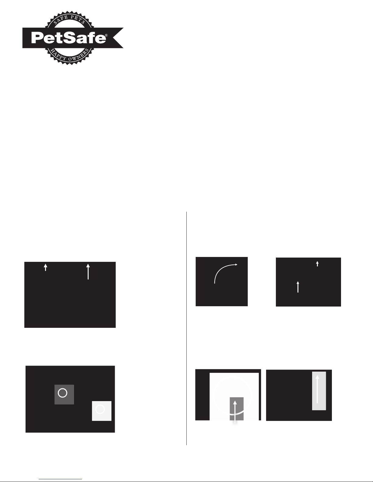
Removing the Conveyor Motor
Cover the work surface with a large sheet, drop cloth, or
newspaper, and then:
1. Remove the conveyor cover and set it aside
(see Figure 1 below).
Figure 1: Removing the conveyor cover
2. Loosen the two thumbscrews that secure the
conveyor to the base (see Figure 2 below)
.
3. Carefully lift up on the
conveyor, until it rests in
an upright position
(see Figure 3 below).
4. Remove the bowl
(see Figure 4 below).
Set the bowl aside.
Figure 3: Conveyor in
an upright position
5. Disconnect the conveyor motor wire from the base.
Press in on the middle of the clip to release the locking
mechanism. If the clip does not easily release, use a fl at
head screwdriver to gently press in at the center of the clip.
Figure 4: Removing
the bowl
Figure 2: Loosening the thumbscrews
Figure 5: Disconnecting the conveyor motor wire
Press in to release
Pull up to unlatch
Page 2
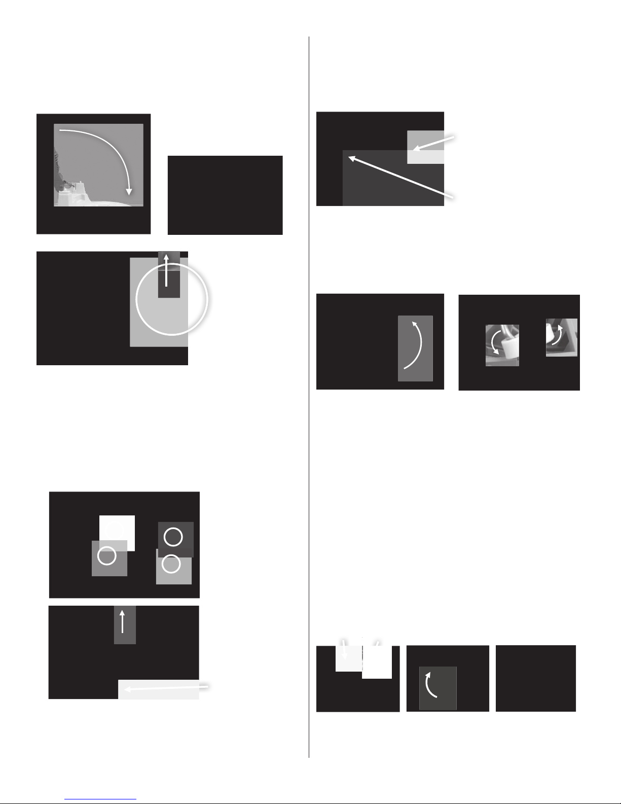
6. Remove the conveyor from the base unit by lowering the
D
conveyor to its natural position fi rst. Next, lift up on the
non-motor corner of the conveyor until the retaining arm
extending down from the conveyor is free from the base
assembly, and then lift the conveyor off the base unit. Set
the conveyor on the work surface.
Lift conveyor
up and out
Replacing the Crank Disk
Turn the conveyor over to expose the crank disk, and then:
1. Rotate the drive shaft until it is fully extended above the
underside of the conveyor (see Figure 8 below).
Crank
disk
Driveshaft
Figure 8: Positioning the drive shaft
2. Lift up on the drive shaft and rotate the crank disk
toward the center of the conveyor assembly. Twist the
bottom of the crank disk towards the drive shaft and then
slip it off the end of the shaft (see Figure 9 below).
Figure 6: Removing the conveyor
7. Remove the motor from the conveyor.
a. Use a #1 Philips screwdriver to remove the retaining
screws and brackets securing the motor to the conveyor
(see Figure 7 “A” below). Set the screws and brackets
aside to be used to attach the new motor.
b. Lift up on the motor to free the motor turn shaft from
the crank disk (see Figure 7 “B” below).
A.
B.
Lift off
motor
Figure 9: Removing the crank disk
NOTE: If a rake fi nger detaches from the drive shaft, hold the
drive shaft steady while gently pressing the rake fi nger against the
shaft to snap it back into place.
3. Attach the replacement crank disk to the drive shaft.
Align the crank disk with the inside surface towards the
drive shaft.
a. Lift the rake-fi nger assembly up to elevate the drive
shaft above the conveyor assembly, and attach the
crank disk to the drive shaft by inserting the exposed
end of the drive shaft into the open channel on the
crank disk (see Figure 10 “A” above).
b. Push the crank disk up and around until it
is perpendicular to the drive shaft (see Figure 10
“B” and “C” above).
Drive shaft Crank disk inside surface
Figure 7: Detaching the motor from the conveyor
www.petsafe.net 2
Crank
disk
A.
Figure 10: Attaching the crank disk to the drive shaft
B. C.
Page 3

Installing the Replacement
Conveyor Motor
To attach the motor to the conveyor:
1. Position the crank disk half-circle hole with the opening
on the side of the conveyor assembly (see Figure 11
below).
Crank disk
half-circle hole
2. Insert the conveyor motor’s drive shaft into the half-circle
hole on the crank disk (see Figure 12 below). Both the
crank disk and motor drive shaft align correctly for a
matched fi t.
Motor
drive shaft
4. Secure the conveyor motor in place with the two plastic
retaining brackets. Attach the semi-circle side towards
the conveyor motor for both brackets. (see Figure 14
below). Replace the screws and tighten with a #1 Philips
screwdriver.
Figure 14: Attaching the retaining brackets
5. Reattach the conveyor assembly to the base unit. First,
insert the plastic post on the motor side of the conveyor
into the cutout on the base unit. Next, then apply gentle
pressure to the retaining arm on the opposite side of the
conveyor while you insert it in the cutout on the other
side of the base unit (see Figure 15 below).
Conveyor
assembly
Crank
disk
Figure 12:
shaft to the crank disk
3. While holding the crank disk up so it does not detach
from the motor drive shaft, turn the motor assembly until
the two fl anges are properly aligned with, and fi tted to the
posts on the conveyor assembly (see Figure 13 below).
Figure 13: Aligning the motor assembly with the motor
posts on the conveyor
Aligning the motor drive
Motor
posts
Base unit
Figure 15: Attaching the conveyor to the base unit
6. Move the conveyor to its upright position, and then
reconnect the conveyor motor wire to the base (see Figure
16 below). Press down until the catch clicks into place.
Push down on clip
Figure 16: Attaching the conveyor motor
wire to the base unit
Completely connected
www.petsafe.net 3
Page 4

7. Flip the base over, move the conveyor to its upright
.
D
position, and then place the bowl back onto the base unit
(see “A” in Figure 17 below). Be sure to adjust your litter
guard so that the conveyor fi ts within the notch on the
guard (see “B” in Figure 17).
A.
B.B
9. Tuck the motor wires into the space between the conveyor
assembly and the base unit so they do not get pinched
between the two. Tighten the two thumbscrews to secure
the conveyor to the base (see Figure 19 below).
Do not pinch wires Wires unpinched
o not pinch wires
Figure 12: Securing the conveyor to the base unit
Figure 17: Replacing the Bowl
8. Lower the conveyor into place (see Figure 18 below).
If your bowl is full of litter, you may gently wiggle the
conveyor back and forth to bury the rake fi ngers in
the litter.
Testing Your Simply Clean® Litter Box
To verify that your repair was completed correctly:
1. Replace the conveyor cover and waste receptacle. Both
have to be in place for the unit to work properly.
2. Plug the unit into the power source. The Operating
Indicator LED should illuminate.
3. Without lifting up on, or removing the conveyor cover,
observe the area at the base of the conveyor for conveyor
movement.
If your conveyor is not moving:
• Make sure the conveyor cover is securely in place and the
waste receptacle is completely installed in its bay.
• Loosen the thumbscrews and lift up the conveyor to verify
that the motor connector is completely and properly
attached to the base unit. (see page 3, Figure 16 for
reference).
If your unit is still not working, contact PetSafe®
Customer Care Center at 1-800-732-2677
Monday – Friday: 8 am - 8 pm EST, or
Saturday: 9 am - 5 pm EST.
Radio Systems Corporation • 10427 Electric Avenue • Knoxville, TN 37932 • 1-800-732-2677 • www.petsafe.net • ©2008 Radio Systems Corporation • 400-1035
 Loading...