

Page 1
RFA-590
Wire Break Locator
Détecteur de rupture de fil
Localizador de rotura de cable
Product Manual
Manuel d’utilisation
Manual del producto
Please read this entire Product Manual before beginning
Veuillez lire ce manuel dʼutilisation dans son intégralité avant de commencer
Por favor, lea detenidamente este manual del producto antes de empezar
Page 2
petsafe.com2
EN
FR
ES
Welcome
You and your pet were made for each other. Our aim is to help you have the best companionship and
the most memorable moments together. The Wire Break Locator is designed to easily help you locate
any wire breaks in your in-ground containment system.
We know that safe pets make happy owners. Before getting started, take a moment to read through the
important safety information. If you have any questions, please do not hesitate to contact us.
Hereinafter Radio Systems Corporation, Radio Systems PetSafe Europe Ltd., Radio Systems Australia
Pty Ltd. and any other affiliate or brand of Radio Systems Corporation may be referred to collectively
as “We” or “Us.”
Important Safety Information
Explanation of attention words and symbols used in this Product Manual
This is the safety alert symbol. It is used to alert you to potential personal injury hazards.
Obey all safety messages that follow this symbol to avoid possible injury or death.
WARNING indicates a hazardous situation which, if not avoided, could result
in death or serious injury.
CAUTION, used with the safety alert symbol, indicates a hazardous situation
which, if not avoided, could result in minor or moderate injury.
NOTICE is used to address practices not related to personal injury.
• Underground cables can carry high voltage. Have all underground cables
marked before you dig to repair or bury your wire. In most areas this is a
free service. Avoid these cables when you dig.
• Follow all safety instructions for your power tools. Be sure to always wear
your safety goggles.
• Do not install, connect, or remove your system during a lightning storm. If the
storm is close enough for you to hear thunder, it is close enough to create
hazardous surges.
• Risk of electric shock. Use the transmitter indoors in a dry location only.
• Risk of injury. Wire on top of the ground may be a trip hazard. Use care in
how you place your wires.
• Watch where you are walking. Stakes driven into the ground can create
obstacles that could cause you to trip.
• Laceration is possible from sharp edges if the telescoping handle
becomes broken.
• Connect power to the wire break location transmitter using the supplied
12VAC power adaptor. Damage to the transmitter will occur if an improper
adaptor is used.
• It is not recommended to use rechargeable batteries. Battery life would be
very short with a rechargeable battery.
• Do not mix old and new batteries.
• Do not mix standard, alkaline or rechargeable batteries.
• Exhausted batteries should be removed immediately. Do not dispose of
batteries with household waste.
Page 3
petsafe.com 3
EN
FR
ES
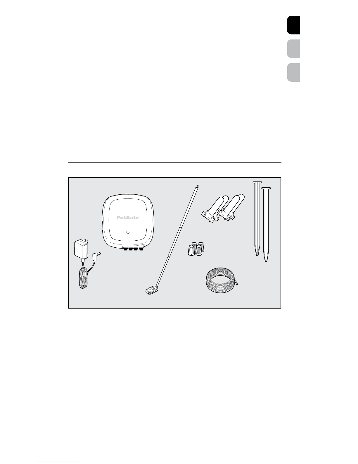
In the Box
Required Components (Not Included)
• 2 AAA batteries for the locator
• We do not recommend using rechargeable batteries—the lights may not work
You May Also Need
• Additional boundary wire
(Part #RFA-1)
• Pliers
• Tape measure
• Wire stripping pliers
• Shovel or lawn edger
• Hammer
• Additional gel-filled capsules and wire nuts
(Part #RFA-366)
For help with setup and training, please visit www.petsafe.com.
What’s Covered
How It Works ....................................................................................................................................................... 4
When to Use the Wire Break Locator ............................................................................................................... 4
Common Locations of Wire Breaks ...................................................................................................................4
Before You Begin .................................................................................................................................................4
Prepare the Transmitter ....................................................................................................................................... 5
Prepare the Stakes ..............................................................................................................................................5
Ground the Stakes .............................................................................................................................................5
Prepare the Locator .............................................................................................................................................6
Using the Locator ................................................................................................................................................6
Find the Wire Break ............................................................................................................................................ 7
Repair the Wire Break ........................................................................................................................................ 8
Reconnect the Wires .......................................................................................................................................... 9
Test the Fence System .........................................................................................................................................9
Terms of Use and Limitation of Liability .......................................................................................................... 10
Compliance .......................................................................................................................................................10
Important Recycling Advice ............................................................................................................................. 11
Warranty ............................................................................................................................................................ 11
Boundary wire – 50 ft. / 15 m
Wire nuts (4)
Grounding
stakes
(2)
Expandable
handle
Locator
Gel-filled
capsules (4)
Wire break
locator transmitter
Power
adaptor
Page 4

petsafe.com4
EN
FR
ES
How It Works
The Wire Break Locator is designed to find complete breaks in your boundary wire. It is not designed
to detect partial wire breaks.
The transmitter sends 2 unique signals to the boundary wires that are connected to it. One boundary
wire receives a continuous low frequency signal and the other boundary wire receives an intermittent
high signal.
A portable locator is used to hear these signals as tones. A break in the wire is detected when the tones
change or disappear. The red and green lights on the locator visually assist you with determining which
tone you are hearing, even if the environment is noisy. The green light indicates the continuous tone,
and the red light indicates the intermittent tone.
When to Use the Wire Break Locator
• Use the Wire Break Locator when there is a wire break indication on the fence transmitter.
Common Locations of Wire Breaks
Please inspect these areas for signs of damage.
Wire breaks are commonly found:
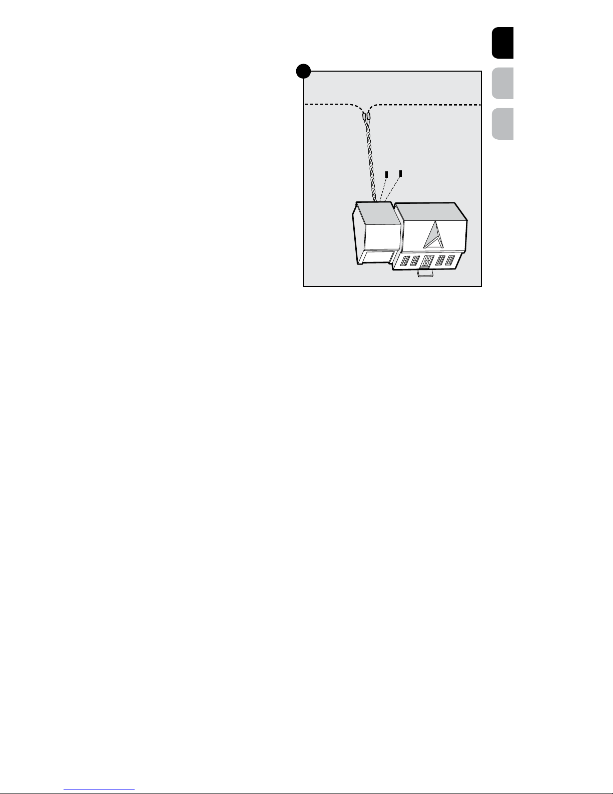
• At the wire exit point of the house
• Where the wire enters the ground from the house, usually caused by string trimmers
• Where the wires cross sidewalks or driveways, usually caused by edging and string trimmers
• Around landscaping and flower beds, usually caused by digging, or working up the soil
• In aerated lawns
• At wire splices where gel-filled capsules have not been installed
• At wire splices without reinforcement knots
Before You Begin
• For proper electrical grounding, the ground must be wet. Several gallons/liters of water may need
to be poured around the grounding stakes in order to moisten dry ground.
• It is acceptable to repair solid boundary wire with stranded boundary wire, or to repair stranded
boundary wire with solid boundary wire, but the same gauge (wire thickness)—such as 20 gauge
wire—must be used with both types of wire.
• Aerated lawns can cut the wire into small sections. It may be easier to replace a long length of wire
instead of small sections.
Page 5

petsafe.com 5
EN
FR
ES
Prepare the Transmitter
1. Place the wire break locator transmitter
in a convenient location near your
fence transmitter.
2. Unplug the power adaptor to the
fence transmitter.
3. Disconnect the twisted boundary wire
and connect it to the wire break locator
transmitter. Press the red tabs on the bottom
of the transmitter labeled LOOP (1A) and
insert the 2 twisted boundary wires into the
terminals (1B).
Prepare the Stakes
Note: The system requires 2 separate
grounding wires to be connected from the
transmitter to individual grounding stakes that
are placed in the ground.
1. Using the spool of wire supplied, strip
3
⁄8 in. (1 cm) of insulation from one end
of the spool. Press one of the black tabs
on the transmitter labeled GROUND
(1A) and insert the stripped end into the
terminal (2A).
2. Next, slip your finger through the wire spool
and unroll the wire by allowing the spool
to rotate on your finger as you walk away
from the transmitter.
3. Once you are outside, cut the wire from
the spool and strip 2 in. (5 cm) of insulation
from the end of the wire in order to connect
it to the grounding stake.
Note: It is recommended to keep the
ground wire as short as possible by
trimming off any excess wire between the
transmitter and the outside location of the
grounding stake.
4. Place the wire through the small hole in
the grounding stake and twist the wire
tightly (2B). Securely wrap the wire around
the stake so the copper makes a solid
connection with the metal (2C).
5. Place the stake on the ground for now
and repeat the steps above for the other
grounding stake.
Ground the Stakes
Note: For proper electrical grounding, the
ground must be wet. You may need to pour
several gallons/liters of water around the
grounding stakes in order to moisten dry
ground.
1. Position the 2 grounding stakes at least
2–3 ft. (0.6–1 m) apart from each other
and insert them into the ground about
8 in. deep (20 cm) with about 2 in. (5 cm)
remaining out of the ground.
2. Recheck the LOOP and GROUND wire
connections at the transmitter and verify
that they are securely installed.
3. Connect the power adaptor to the power
jack on the side of the transmitter and then
plug the power adaptor into a working
outlet. The green power light will turn on,
indicating that power is supplied.
LOOP/
PÉRIMÈTRE
GROUND/
PRISE TERRE
Twisted
boundary
wire
1A
1B
Ground
wire
2A
2B
2C
Page 6
petsafe.com6
EN
FR
ES
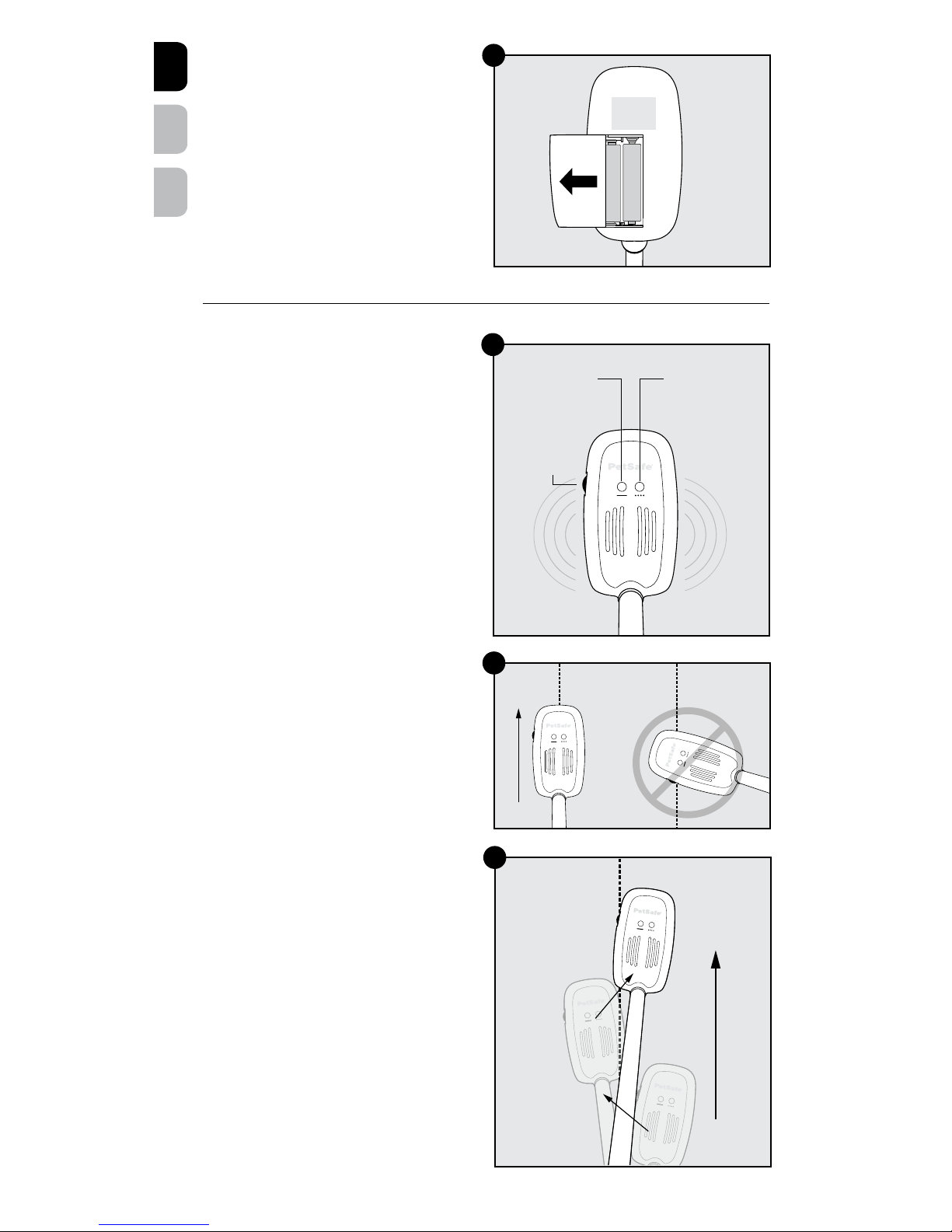
Prepare the Locator
• Place 2 AAA Alkaline batteries (not included)
inside the bottom of locator (3A).
• Rechargeable batteries are not
recommended.
• Battery life for the locator is approximately
20 hours.
• A 2-toned alarm on the locator will indicate
when the batteries need to be replaced.
Using the Locator
Power/Volume
Rotate the dial on the side of the locator to turn
it on. The lights will flash. To adjust the volume,
rotate the dial up or down (4A).
Light Indicator
The red and green lights on the locator are
included to visually assist you with determining
which tone you are hearing if it is difficult to
hear the tones. The green light indicates the
continuous tone and the red light indicates the
intermittent tone (4A).
Individual Tones
Note: Visit www.petsafe.com to view the Wire
Break Locator video. You will see a product
demonstration and hear the 2 different tones.
To become familiar with the individual
tones, place the locator over one of the
single ground wires that is connected to the
transmitter and then move the locator over
the other ground wire. Each wire will emit a
unique tone. Be sure the 2 ground wires are
separated by several feet/metres to prevent
both tones from being activated together.
Combined Tones
To become familiar with the combined tones,
place the locator over the twisted wire that is
connected to the transmitter to hear both the
low frequency continuous tone and the higher
frequency intermittent tone together.
Operation
The locator must be parallel to the buried
boundary wire for proper signal reception
(4B). The tone from the locator will be heard
best when it is directly above the buried wire.
Swing the locator from side to side (4C) as you
move along the wire. Follow the path of the
wire by walking in the direction of the loudest
tone volume.
AAA
AAA
3A
Boundary wire
4C
4B
Continuous
tone
(green)
Intermittent
tone
(red)
On/Off
Volume
dial
4A
Boundary
wire
Page 7
petsafe.com 7
EN
FR
ES
Find the Wire Break
For Systems with Twisted
Boundary Wire
• If a single wire in the twisted wire is broken,
you will hear both tones until the locator
reaches the break in the wire. Then you will
hear only a single tone.
• If both of the wires are broken in the twisted
wire, the volume from the locator will
decrease as you approach the break. The
tone will stop after you have passed the
break and the lights will disappear.
1. Begin outside where the twisted boundary
wire exits through a window, door or
wall (5A).
2. Place the locator directly over the buried
wire. The locator will pick up the 2
transmitted tones of the buried twisted
boundary wire. As a result you will hear both
the low frequency continuous tone and the
high frequency intermittent tone together.
3. Adjust the volume so that the tones are loud
enough to hear over normal outdoor noise.
4. Walk along the path and swing the
locator from side to side, listening for the
simultaneous tones (4C). The light that is
associated with the strongest signal will be lit.
Check the Boundary Wire Loop
• If there is a single break in the boundary loop, the tone will most likely change from one tone to
another (intermittent to continuous or from continuous to intermittent). The lights will also switch from
one color to the other. Ideally, if the tone disappears, you have located the break directly below
the locator.
• If there are multiple breaks in the boundary loop, the locator tone will decrease and will go silent
at the break, and the lights will turn off.
1. If you do not locate a break in the twisted wire, then you will eventually reach the splice where
the twisted wire meets the boundary wire loop in your yard (5A). You will only hear a single tone
(either intermittent or continuous) from one of the single boundary wires. You will also see only one
color on the locator (either red or green).
2. Select a direction and walk the boundary wire loop while listening for a change in tone or color.
Note: It may be difficult to hear the changes between tones due to the loud volume on the locator.
When you do hear a change in tone, stop and turn the volume down on the locator until you barely
hear the tone when you are directly over the wire. Move the locator towards the area of the wire
break. When the tone disappears, you have located the exact location of the break directly below the
locator.
We recommend repairing the breaks as you go around the entire loop.
Note: If the lawn was aerated there might be multiple breaks throughout the wire. It may be easier to
replace a long section of wire rather than making several small repairs. To do this, go back to where
the twisted wire meets the boundary loop and check the boundary wire loop in the opposite direction
this time. Once you find the break in the wire then you can estimate how long of a section of wire you
will need to replace.
Things to Keep In Mind
• As you move further from the transmitter, the locator volume will gradually decrease. This is not to
be confused with a wire break. You may need to increase the locator volume in order to continue
hearing the signal.
• If the twisted wire is greater than 50 ft. (15 m) and there are off-limits areas such as gardens and
pools in your boundary layout, you may need to locate the break by listening for a reduction in the
tone volume.
• If the twisted wire is greater than 100 ft. (30 m), the intermittent tone and the continuous tone will
most likely be combined over the entire boundary wire. If this occurs, you will hear a noticeable
reduction in the tones when the locator is over the break, and the colors may not change over
the break.
Boundary wire loop
Twisted
boundary
wire
Start here
Splice
Grounding
stakes
5A
Page 8
petsafe.com8
EN
FR
ES
Repair the Wire Break
When you find the location of the wire break,
you will need to dig down to the wire to make
the repairs.
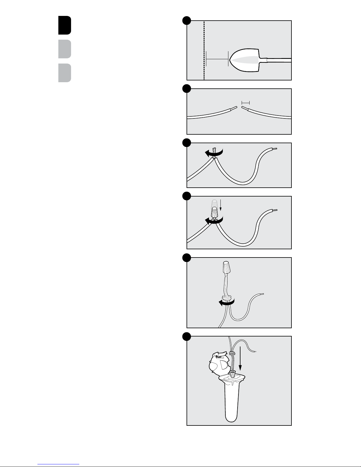
1. Begin digging 4–5 in. (10–12 cm) to
the side of the buried wire (6A). Wire
is typically buried 1–3 in. (2.5–7 cm)
below the ground. Be certain to dig with
the shovel blade parallel to the wire,
otherwise you could cause additional
damage to the wire.
2. Dig slowly toward the wire until it is
exposed. Strip approximately
3
⁄8 in.
(1 cm) of insulation from the ends of each
damaged boundary wire (6B). If the
boundary wire is corroded, cut it off and
remove more insulation to expose clean
copper wire.
Note: You will need to cut a new piece of
wire from the spool provided in order to
splice together the 2 broken boundary wires.
Make sure to have at least 1 ft. (30 cm) of
wire for small repairs. When repairing a large
section of wire, make sure that the new wire
extends at least 2 ft. (60 cm) longer than the
distance between the 2 ends of the exposed
boundary wire.
3. Take the end of the boundary wire and
the end from the new wire and twist the 2
stripped ends together (6C).
4. Place the wire nut over the spliced wires
and twist the wire nut around the wires
(6D). Make sure there is no copper
exposed beyond the end of the wire nut.
5. Tie a knot 3–4 in. (7–10 cm) from the wire
nut (6E). Make sure the wire nut is secure
on the wire splice.
6. Open the lid of the gel-filled splice
capsule and insert the wire nut as deeply
as possible into the waterproof gel inside
the capsule (6F).
4-5 in.
Boundary
wire
10-12 cm
6A
³⁄₈ in./1 cm
6B
6C
6D
6E
6F
Page 9
petsafe.com 9
EN
FR
ES
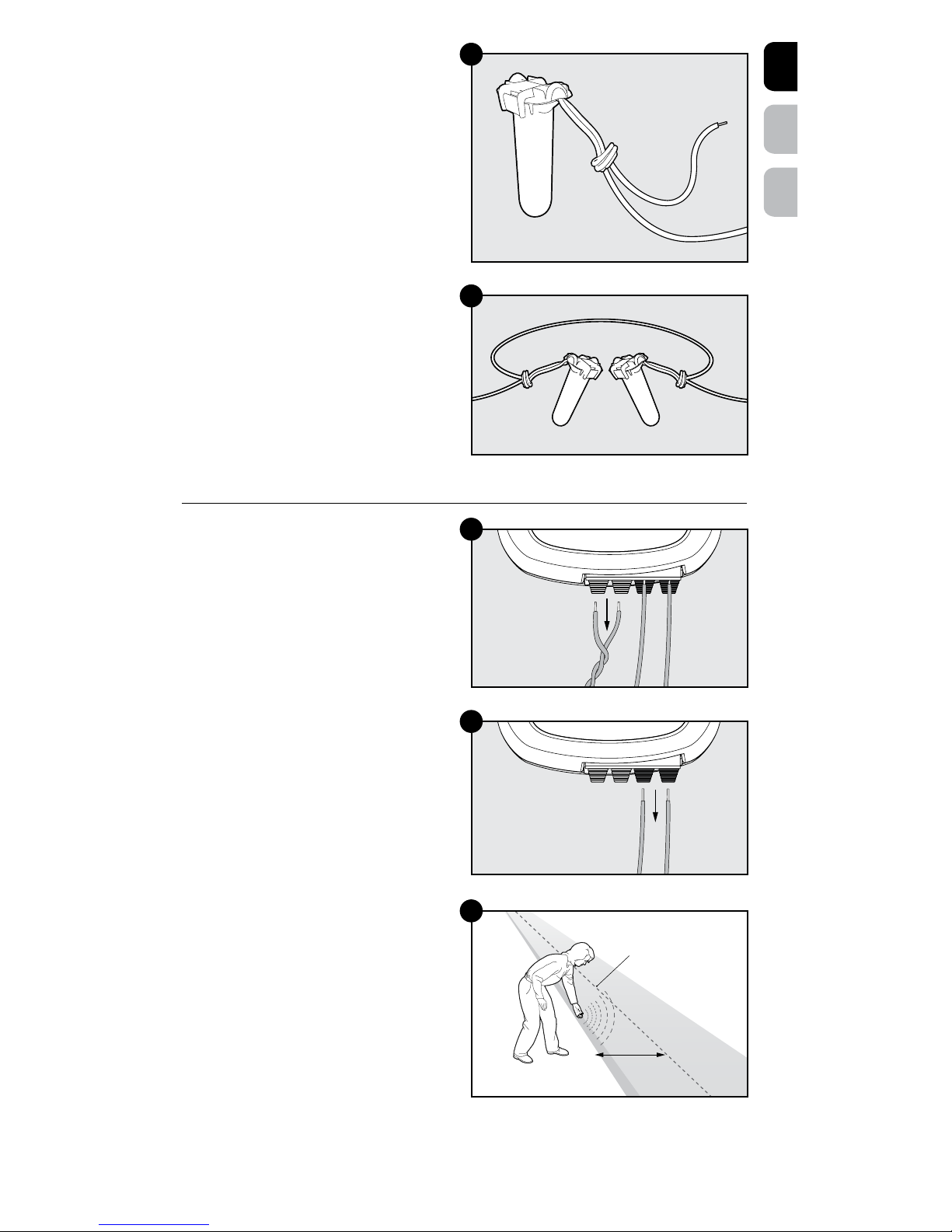
7. Snap the lid of the capsule shut (6G). The
splice connection must be waterproof for
proper system performance.
Note: If your splice pulls loose, the entire
system will fail. Make sure your splice is
secure. Additional gel-filled splice capsules
and wire nuts are available through the
Customer Care Center.
8. Repeat for the other end of the buried
wire break.
The damaged wire should now be spliced
together with the new section of boundary
wire (6H).
Reconnect the Wires
After you have repaired the wire break, take
the locator and continue walking around
the entire boundary to verify that there
are no more wire breaks. If there are no
more wire breaks, you will hear intermittent
and continuous tones all the way around
the boundary.
Go back inside your home and disconnect
the 2 twisted boundary wires from the loop
terminals (7A) and connect them back to your
fence transmitter. Check that the loop light is lit
on the fence transmitter. If it is not lit, there may
be another break in the wire.
Disconnect the 2 ground wires (7B) and
store them along with the grounding stakes
in case you need to check for wire breaks in
the future.
Test the Fence System
Verify that your system is working with
the receiver collar. Slowly approach the
boundary wire while holding your test light
tool firmly on the receiver collar contact points
(7C). The test light tool will light up as the
receiver collar sends a static correction.
Verify that the receiver collar activates
approximately 6–10 ft. (1.8–3 m) from the
boundary wire as a warning zone before
placing the receiver collar on your pet.
Boundary
wire
6–10 ft.
(1.8–3.0 m)
7A
7B
7C
6G
6H
Page 10

petsafe.com10
EN
FR
ES
Terms of Use and Limitation of Liability
1. Terms of Use
The use of this product is subject to your acceptance without modification of the terms, conditions
and notices contained with this product. Use of this product implies acceptance of all such terms,
conditions, and notices. If you do not wish to accept these terms, conditions, and notices, please
return the product, unused, in its original packaging and at your own cost and risk to the relevant
Customer Care location together with proof of purchase for a full refund.
2. Proper Use
Proper use includes, without limitation, reviewing the entire Product Manual and any specific safety
information statements. The specific temperament or size/weight of your pet may not be suitable
for this product. If you are unsure whether this product is appropriate for your pet, please consult
your veterinarian or certified trainer prior to use. For products used with pets where training is
desired, Radio Systems Corporation recommends that these training products are not used if your
pet is aggressive and accepts no liability for determining suitability in individual cases.
3. No Unlawful or Prohibited Use
This product is designed for use with pets only. This product is not intended to harm, injure or
provoke. Using this product in a way that is not intended could result in violation of Federal, State
or local laws.
4. Limitation of Liability
In no event shall Radio Systems Corporation or any of its associated companies be liable for (i)
any direct, indirect, punitive, incidental, special or consequential damage and/or (ii) any loss
or damages whatsoever arising out of or connected with the use or misuse of this product. The
purchaser assumes all risks and liability from the use of this product to the fullest extent permissible
by law.
5. Modification of Terms and Conditions
Radio Systems Corporation reserves the right to change the terms, conditions and notices
governing this product from time to time. If such changes have been notified to you prior to your use
of this product, they shall be binding on you as if incorporated herein.
Compliance
FCC
This device complies with part 15 of the FCC Rules. Operation is subject to the following two
conditions: (1) This device may not cause harmful interference, and (2) this device must accept any
interference received, including interference that may cause undesired operation.
NOTE: This equipment has been tested and found to comply with the limits for a Class B digital device,
pursuant to part 15 of the FCC Rules. These limits are designed to provide reasonable protection
against harmful interference in a residential installation. This equipment generates, uses, and can
radiate radio frequency energy and, if not installed and used in accordance with the instructions, may
cause harmful interference to radio communications. However, there is no guarantee that interference
will not occur in a specific installation. If interference does occur to radio or television reception, which
can be determined by turning the equipment off and on, the user is encouraged to try to correct the
interference by one or more of the following measures:
• Relocate the interfered receiving antenna.
• Increase the separation between the equipment and locator.
• Connect the equipment into an outlet on a circuit different to that to which the locator is connected.
• Contact the Customer Care Center at +1 (800) 732-2677.
CAUTION: Modification or changes to this equipment not expressly approved by Radio Systems
Corporation may void the user’s authority to operate the equipment.
IC
This device complies with Industry Canada license-exempt RSS standard(s). Operation is subject to the
following two conditions: (1) this device may not cause interference, and (2) this device must accept
any interference, including interference that may cause undesired operation of the device.
Page 11

petsafe.com 11
EN
FR
ES
Important Recycling Advice
Please respect the Waste Electrical and Electronic Equipment regulations in your country. This
equipment must be recycled. At the end of the product life, do not place it in the normal municipal
waste system. Please check the regulations in your area or return it to where it was purchased so that it
can be placed in our recycling system. If these options are not possible, please contact the Customer
Care Center for further information.
Warranty
One Year Non-Transferable Limited Warranty
This Product has the benefit of a limited manufacturer’s warranty. Complete details of the warranty
applicable to this Product and its terms can be found at www.petsafe.com and/or are available by
contacting your local Customer Care Center.
Radio Systems Corporation
10427 PetSafe Way
Knoxville, TN 37932 USA
Page 12

petsafe.com12
EN
FR
ES
Bienvenue
Vous et votre animal êtes faits l’un pour l’autre. Notre objectif est de vous aider à avoir la meilleure
des camaraderies et à passer ensemble les moments les plus mémorables. Le détecteur de rupture de
fil est prévu pour vous permettre de trouver facilement tout point de rupture dans votre système antifugue enterré.
Nous savons qu’un animal en sécurité rend son propriétaire heureux. Avant de commencer, merci de
prendre le temps de lire les informations de sécurité importantes. N’hésitez pas à nous contacter si
vous avez des questions.
Ci-après, « Nous » peut renvoyer collectivement à Radio Systems Corporation, Radio Systems PetSafe
Europe Ltd., Radio Systems Australia Pty Ltd. ainsi qu’à toute autre filiale ou marque de Radio Systems
Corporation.
Consignes de sécurité importantes
Description des termes d’avertissement et symboles utilisés dans ce manuel d’utilisation
Ce symbole est une alerte de sécurité. Il est utilisé pour vous alerter des risques de blessures.
Veuillez respecter tous les messages de sécurité qui suivent ce symbole pour éviter tout
risque de blessure ou de décès.
AVERTISSEMENT indique une situation dangereuse qui, si elle n’est
pas évitée, risque d’entraîner la mort ou des blessures graves.
ATTENTION, utilisé avec un symbole d’alerte de sécurité, indique
une situation dangereuse qui, si elle n’est pas évitée, pourrait
entraîner des blessures légères à modérées.
AVIS indique les pratiques qui ne sont pas relatives aux blessures
corporelles.
• Les câbles souterrains peuvent être à haute tension. Faites marquer
l’emplacement de tous les câbles souterrains avant de creuser
pour enterrer votre fil. Dans la plupart des endroits, ce service est
gratuit. Évitez ces câbles lorsque vous creusez.
• Veuillez respecter toutes les consignes de sécurité pour vos outils
électriques. Veillez à toujours porter des lunettes de protection.
• N’installez pas, ne connectez pas et ne retirez pas votre système
par temps orageux. Si l’orage est suffisamment proche pour
que vous entendiez du tonnerre, il est suffisamment proche pour
provoquer des surtensions dangereuses.
• Risque d’électrocution. Utilisez l’émetteur de clôture à l’intérieur et
seulement dans un emplacement sec.
• Risque de blessure. Laissé sur le sol, le fil représente un risque de
chute. Placez vos câbles avec soin.
• Regardez où vous marchez. Les piquets enfoncés dans le sol
peuvent créer des obstacles et vous faire trébucher.
• Des lacérations peuvent être causées par des bords tranchants si
la poignée télescopique est cassée.
• Raccorder l’alimentation à l’émetteur du détecteur de rupture de fil
en utilisant l’adaptateur 12VCA fourni. L’utilisation d’un adaptateur
inapproprié endommagera l’émetteur.
• Il n’est pas recommandé d’utiliser des piles rechargeables.
L’autonomie des piles peut être extrêmement courte avec une
pile rechargeable.
• N’utilisez pas à la fois des piles neuves et des piles usées.
• Ne pas utiliser à la fois des piles alcalines standard et des
piles rechargeables.
• Les piles déchargées doivent être immédiatement retirées. Ne pas
jeter les piles avec les ordures ménagères.
Page 13

petsafe.com 13
EN
FR
ES
Dans la boîte
Composants nécessaires (Non inclus)
• 2 piles AAA pour le détecteur
• Nous ne recommandons pas l’utilisation de piles rechargeables : les voyants risquent de ne
pas fonctionner.
Outils complémentaires :
• Fil d’antenne supplémentaire
(référence du produit : RFA-1)
• Pince
• Mètre ruban
• Pinces à dénuder
• Pelle ou coupe-gazon
• Marteau
• Capsules remplies de gel et connecteurs
supplémentaires (référence du produit : RFA-366)
Pour obtenir une assistance lors de l’installation et du dressage, visitez notre site
www.petsafe.com.
Sommaire :
Fonctionnement du système .............................................................................................................................14
Quand utiliser le détecteur de rupture de fil ? ...............................................................................................14
Détections courantes de rupture de fil ............................................................................................................14
Avant de commencer ........................................................................................................................................14
Préparation de l’émetteur ................................................................................................................................15
Préparez les piquets ..........................................................................................................................................15
Mise à la terre des piquets ............................................................................................................................... 15
Préparation du détecteur..................................................................................................................................16
Utilisation du détecteur .....................................................................................................................................16
Trouver la rupture de fil.....................................................................................................................................17
Réparation d’une rupture .................................................................................................................................18
Reconnecter les fils ........................................................................................................................................... 19
Tester le système de clôture..............................................................................................................................19
Conditions d’utilisation et limitation de responsabilité ................................................................................ 20
Conformité ........................................................................................................................................................ 20
Remarque importante concernant le recyclage ............................................................................................21
Garantie .............................................................................................................................................................21
Fil d'antenne 15m/50pi
Connecteurs (4)
Piquets de mise
à la terre
(2)
Poignée
télescopique
Détecteur
Capsules remplies
de gel (4)
Détecteur de
rupture de fil
Adaptateur
Page 14

petsafe.com14
EN
FR
ES
Fonctionnement du système
Le détecteur de rupture de fil est prévu pour trouver les coupures totales dans votre fil d’antenne. Il n’est
pas prévu pour détecter des coupures de fil partielles.
L’émetteur envoie 2 signaux uniques aux fils d’antenne qui y sont reliés. Un fil d’antenne reçoit
un signal continu de basse fréquence et l’autre fil d’antenne reçoit un signal intermittent de
haute fréquence.
Un détecteur portable est utilisé pour entendre ces signaux sous forme de signaux sonores. Une
coupure dans le fil est détectée lorsque le signal sonore change ou disparaît. Les voyants rouge et vert
sur le détecteur vous aident à déterminer quel signal sonore vous entendez même si l’environnement est
bruyant. Le voyant vert indique le signal sonore continu et le rouge indique le signal sonore intermittent.
Quand utiliser le détecteur de rupture de fil ?
• Utilisez le détecteur de rupture de fil lorsqu’une coupure de fil est indiquée sur l’émetteur
de clôture.
Détections courantes de rupture de fil
Inspectez ces zones pour déceler tout signe de dommage.
Les ruptures de fil se retrouvent généralement aux endroits suivants :
• Au point de sortie du fil de la maison
• À l’endroit où le fil entre dans le sol depuis la maison, généralement à cause du taille-bordures
• À l’endroit où les fils passent sur le trottoir ou l’allée de garage, souvent causées par des taillebordures et taille-haies
• Autour des parterres et aménagements paysagers, souvent causée par le travail de la terre ou le
fait de creuser
• Sur les pelouses aérées
• Au niveau des épissures de fil, aux endroits où aucune capsule de gel n’a été posée
• Au niveau des épissures de câble qui ne sont pas dotées de nœuds de renforcement
Avant de commencer
• Pour une mise à la terre efficace, le sol doit être humide. Il peut être nécessaire de répandre
quelques litres d’eau autour des piquets de mise à la terre de façon à humidifier le sol.
• Il est possible de réparer un fil d’antenne plein avec du fil d’antenne torsadé ou de réparer un fil
d’antenne torsadé avec du fil d’antenne plein mais le même calibre de fil (épaisseur du fil), par
exemple du fil de calibre 20, doit être utilisé pour les deux types de câble.
• L’aération des pelouses peut couper le fil en petits morceaux. Il peut être plus facile de remplacer
une grande longueur de fil plutôt que réparer des petits morceaux.
Page 15

petsafe.com 15
EN
FR
ES
Préparation de l’émetteur
1. Placer le détecteur de rupture de fil dans
un endroit pratique près de votre émetteur
de clôture.
2. Débranchez l’adaptateur électrique de
l’émetteur de clôture.
3. Déconnectez le fil d’antenne torsadé et
connectez-le à l’émetteur du détecteur de
rupture de fil. Appuyez sur les languettes
rouges situées en bas du transmetteur
portant la mention PÉRIMÈTRE (1A) et
insérez les deux fils d’antenne torsadés
dans les bornes (1B).
Préparez les piquets
Remarque : le système nécessite que 2 fils
de terre distincts soient reliés de l’émetteur
individuel aux piquets de mise à la terre qui
sont placés dans le sol.
1. Utilisez la bobine de fil fournie, retirez
1 cm (
3
⁄8 po) de gaine à l’une des extrémités
de la bobine. Sur l’émetteur, appuyez sur
les languettes noires portant la mention
PRISE TERRE (1A) et insérez l’extrémité
dénudée dans la borne (2A).
2. Glissez ensuite votre doigt dans la bobine
de fil et déroulez le fil en laissant la bobine
tourner autour de votre doigt tout en vous
éloignant de l’émetteur.
3. Une fois à l’extérieur, coupez le fil et retirez
5 cm (2 po) de gaine à l’extrémité du fil
afin de le raccorder sur le piquet de mise à
la terre.
Remarque : il est recommandé de laisser
le fil de terre aussi court que possible en
coupant l’excédent de fil entre l’émetteur
et la position extérieure du piquet de mise
à la terre.
4. Passez le fil à travers le petit trou dans le
piquet de mise à la terre et torsadez le
fil très serré (2B). Entourez fermement le
fil autour du piquet de façon à ce que le
cuivre forme une bonne connexion avec le
métal (2C).
5. Placez le piquet sur le sol pour le moment et
répétez les étapes ci-dessus pour les autres
piquets de mise à la terre.
Mise à la terre des piquets
Remarque : pour une mise à la terre correcte,
le sol doit être humide. Vous devrez peut-être
répandre quelques litres d’eau autour des
piquets de mise à la terre de façon à humidifier
le sol.
1. Placez les 2 piquets à au moins 0,6 à 1 m
(2 à 3 pi) de distance l’un de l’autre et
enfoncez-les dans le sol à environ 20 cm
(8 po) de profondeur en laissant environ
5 cm (2 po) dépasser du sol.
2. Revérifier les connexions PÉRIMÈTRE et
PRISE TERRE du fil sur l’émetteur et vérifiez
qu’elles sont solidement fixées.
3. Raccordez l’adaptateur à la prise électrique
sur le côté de l’émetteur et branchez ensuite
l’adaptateur dans une prise fonctionnelle.
Le voyant vert d’alimentation va s’allumer
pour indiquer que le système est alimenté.
LOOP/
PÉRIMÈTRE
GROUND/
PRISE TERRE
Fil d’antenne
torsadé
1A
1B
Câble de
mise à la
terre
2A
2B
2C
Page 16

petsafe.com16
EN
FR
ES
Préparation du détecteur
• Insérez 2 piles alcalines AAA (non
fournies) dans le compartiment en bas du
détecteur (3A).
• Il n’est pas recommandé d’utiliser des
piles rechargeables.
• L’autonomie des piles du détecteur est
d’environ 20 heures.
• Un signal sonore 2 tons sur le détecteur
indiquera que les piles doivent
être remplacées.
Utilisation du détecteur
Marche / Volume
Tourner le bouton sur le côté du détecteur pour
le mettre en fonction. Les voyants clignotent.
Pour ajuster le volume, tournez le bouton vers
le haut ou vers le bas (4A).
Voyant indicateur
Les voyants rouge et jaune sur le détecteur
sont prévus pour vous aider visuellement à
déterminer quel signal sonore vous entendez
lorsqu’il est difficile d’entendre les signaux
sonores. Le voyant vert indique le signal
sonore continu et le rouge indique le signal
sonore intermittent (4A).
Signaux sonores individuels
Remarque : consultez www.petsafe.com
pour visualiser la vidéo du détecteur de
rupture de fil. Vous verrez une démonstration
d’utilisation du produit et entendrez les 2
différents signaux sonores.
Pour vous familiariser avec les signaux sonores
individuels, placez le détecteur sur l’un des
fils de terre individuels connecté à l’émetteur
puis déplacez l’émetteur au dessus du fil de
terre. Chaque fil émettra un signal différent.
Assurez-vous que 2 fils de terre sont séparés
de plusieurs mètres / pieds pour éviter que les
signaux sonores ne s’activent en même temps.
Signaux sonores combinés
Pour vous familiariser avec les signaux
combinés, placez le détecteur par dessus
le fil de terre torsadé qui est connecté à
l’émetteur pour entendre à la fois le signal
basse fréquence continu et le signal haute
fréquence intermittent.
Fonctionnement
Le détecteur doit être parallèle au fil
d’antenne enterré pour une bonne réception
du signal (4B). Le signal sonore du détecteur
s’entend mieux quand il est directement relié
au fil enterré.
Balancez le détecteur d’un côté à l’autre (4C)
tout en vous déplaçant le long du fil. Suivez le
chemin du fil en marchant dans la direction du
signal sonore le plus fort.
AAA
AAA
3A
Fil d’antenne
4C
4B
Signal sonore
continu
(vert)
Signal
sonore
intermittent
(rouge)
Bouton
marche/
arrêt
4A
Fil d’antenne
Page 17

petsafe.com 17
EN
FR
ES
Trouver la rupture de fil
Pour les systèmes avec fils d’antenne torsadés
• Si un seul fil dans le fil torsadé est cassé, vous
entendrez les deux signaux sonores jusqu’à
ce que le détecteur atteigne la rupture dans
le fils. Vous entendrez alors un signal unique.
• Si les deux fils sont cassés dans le fil torsadé,
le volume du détecteur diminuera au fur et à
mesure que vous approcherez de la rupture.
Le signal sonore s’arrêtera si vous dépassez
la rupture et les voyants disparaîtront.
1. Commencez à l’extérieur là où le fil
d’antenne torsadé sort par une fenêtre, une
porte ou un mur (5A).
2. Placez le détecteur au dessus du fil enterré.
Le détecteur captera les 2 signaux émis
par le fil d’antenne torsadé enterré. Vous
entendrez donc en même temps le signal
sonore basse fréquence continu et le signal
sonore haute fréquence intermittent.
3. Ajustez le volume de façon à ce que les
signaux sonores soient suffisamment forts
pour que vous les entendiez par dessus le
bruit habituel de l’extérieur.
4. Marchez le long du fil et balancez le
détecteur d’un côté à l’autre en écoutant pour entendre les signaux sonores simultanés (4C). Le
voyant associé avec le signal sonore le plus fort s’allumera.
Vérifiez la boucle du fil d’antenne
• Si une seule rupture est présente sur la boucle de clôture, le signal sonore passera probablement
de l’un à l’autre (intermittent puis continu ou continu puis intermittent). Les voyants passeront
également d’une couleur à l’autre. Dans l’idéal, si les signaux sonores disparaissent, vous avez
localisé la rupture directement sous le détecteur.
• En cas de ruptures multiples dans la boucle de clôture, le signal sonore du détecteur va diminuer
jusqu’à devenir silencieux à l’emplacement de la rupture et les voyants s’éteindront.
1. Si vous ne trouvez pas une rupture dans le fil torsadé, alors vous avez probablement atteint la
jointure entre le fil torsadé et la boucle du fil d’antenne dans votre jardin (5A). Vous entendrez
un signal sonore unique (intermittent ou continu) émit par l’un des fils d’antenne. Vous verrez
également une seule couleur sur le détecteur (soit rouge soit vert).
2. Choisissez une direction et marchez le long de la boucle du fil d’antenne tout en écoutant pour
détecter un changement de signal sonore ou de couleur.
Remarque : il peut être difficile d’entendre les changements entre les signaux sonores du fait du
volume élevé sur le détecteur. Lorsque vous entendez un changement de signal sonore, arrêtez-vous
et baissez le volume sur le détecteur jusqu’à ce que vous n’entendiez presque plus le signal sonore
lorsque vous êtes directement sur le fil. Déplacez le détecteur vers la zone de la rupture du fil. Lorsque
le signal sonore disparaît, vous avez trouvé l’emplacement exact de la rupture directement sous
le détecteur.
Nous recommandons de réparer les ruptures au fur et à mesure que vous faites le tour complet de
la boucle.
Remarque : si la pelouse à été aérée, il peut y avoir de nombreuses ruptures tout au long du fil. Il
peut être plus facile de remplacer une longue section de fil plutôt que de faire de plusieurs petites
réparations. Pour ce faire, retournez là où le fil torsadé est raccordé avec la boucle de clôture et
vérifiez la boucle du fil d’antenne dans la direction opposée cette fois. Lorsque vous avez trouvez la
rupture dans le fil vous pouvez estimer la longueur de la section de fil que vous devez remplacer.
Éléments à garder à l’esprit
• Le volume du détecteur va diminuer progressivement au fur et à mesure que vous vous éloignez
de l’émetteur. Il ne faut pas confondre cela avec une rupture de fil. Vous aurez peut-être besoin
d’augmenter le volume du détecteur pour continuer à entendre le signal.
• Si le fil torsadé est plus long que 15 m (50 pi) et qu’il y a des zones hors limites comme des jardins
ou des piscines dans votre plan de clôture, vous devrez trouver la rupture en écoutant pour
détecter une diminution du volume du signal sonore.
• Si le fil torsadé est plus long que 30 m (100 pi), les signaux sonores intermittent et continu seront
probablement combinés sur l’intégralité du fil de clôture. Si cela se produit, vous noterez une
diminution notoire des signaux sonores lorsque le détecteur est au dessus d’une rupture et les
couleurs ne devraient plus changer au dessus de la rupture.
Boucle de fil d’antenne
Fil
d’antenne
torsadé
Commencez ici
Épissure
Mise à la
terre piquets
5A
Page 18

petsafe.com18
EN
FR
ES
Réparation d’une rupture
Quand vous avez trouvé l’emplacement de la
rupture de fil, vous devrez sortir le fil de terre
pour effectuer la réparation.
1. Commencez à creuser 10 à 12 cm
(4 à 5 po) sur le côté du fil enterré
(6A). Le fil est généralement enterré à
2,5 à 7 cm (1 à 3 po) de profondeur.
Assurez-vous de creuser avec le tranchant
de la pelle parallèle au fil, sinon
vous risquez de causer des domages
supplémentaires au fil.
2. Creusez lentement vers le fil jusqu’à ce
qu’il soit visible. Retirez environ 1 cm
(
3
⁄8 po) de gaine à l’extrémité de chaque
fil d’antenne (6B). En cas de corrosion,
coupez-en une partie et retirer plus de
gaine pour exposer la partie en cuivre en
bon état.
Remarque : vous devrez couper un nouveau
morceau de fil de la bobine fournie afin de
relier ensemble les deux parties cassées du
fil d’antenne. Assurez-vous d’avoir au moins
30 cm (1 pi) de fil pour les petites réparations.
Lorsque vous réparez une grande section
de fil, assurez-vous que le nouveau fil est au
moins 60 cm (2 pi) plus long que la distance
entre les 2 extrémités du fil d’antenne.
3. Prenez l’extrémité du fil d’antenne et
l’extrémité du nouveau fil et torsadez les
deux parties dénudées ensemble (6C).
4. Placez le raccord de fils au dessus de
l’épissure des fils et torsadez le raccord
autour des fils (6D). Assurez-vous
qu’aucune partie en cuivre n’est exposée
au-delà de l’extrémité du raccord.
5. Faites un noeud à environ 7 à 10 cm
(3 à 4 po) du raccord (6E). Assurez-vous
que le connecteur soit bien en place sur
la jonction.
6. Ouvrez le couvercle de la capsule de gel
hydrofuge et insérez-y le raccord aussi
profondément que possible (6F).
10 à 12 cm
Fil d’antenne
4 à 5 po
6A
1 cm (³⁄₈ po)
6B
6C
6D
6E
6F
Page 19

petsafe.com 19
EN
FR
ES
7. Fermez le couvercle de la capsule (6G).
Pour un bon fonctionnement du système, la
jonction doit être étanche.
Remarque : si une épissure se détache,
le système entier cessera de fonctionner.
Assurez-vous que vos épissures sont solides.
Il est possible de se procurer des capsules
d’épissure emplies de gel et des connecteurs
supplémentaires auprès du service clientèle.
8. Répétez l’opération pour l’autre extrémité
de la rupture du fil enterré.
Le fil endommagé ne doit pas être raccordé
avec la nouvelle section de fil d’antenne (6H).
Reconnecter les fils
Après avoir réparé la rupture de fil, prenez
le détecteur et continuez à marcher sur
l’intégralité de la clôture pour vérifier qu’il n’y
a pas d’autre rupture. S’il n’y a pas d’autre
rupture, vous entendrez les signaux sonores
intermittent et continu tout le long de la clôture.
Retournez à l’intérieur de votre maison et
déconnectez les deux fils d’antenne des
bornes de boucle (7A) et reconnectez-les sur
l’émetteur de votre clôture. Vérifiez que le
voyant de boucle est allumé sur l’émetteur de
clôture. S’il n’est pas allumé, il doit y avoir une
autre rupture dans le fil.
Déconnectez les 2 fils de terre (7B) et rangezles avec les piquets de mise à la terre au cas
où vous auriez à nouveau besoin de détecter
des ruptures de fil à l’avenir.
Tester le système de clôture
Vérifiez le fonctionnement du système avec
le collier-récepteur. Approchez doucement
du fil d’antenne tout en tenant votre clé
multifonctions fermement sur les contacteurs
du collier-récepteur (7C). La clé multifonctions
s’allumera lorsque le collier-récepteur enverra
une correction électrostatique.
Vérifiez que le collier-récepteur s’active à
environ 1,8 à 3 m (6 à 10 pi) du fil d’antenne
pour créer une zone d’avertissement avant de
placer le collier-récepteur sur votre animal.
Fil d’antenne
1,8 à 3 m
(6 à 10 pi)
7A
7B
7C
6G
6H
Page 20

petsafe.com20
EN
FR
ES
Conditions d’utilisation et limitation de responsabilité
1. Conditions d’utilisation
L’utilisation de ce produit est sujette à votre acceptation sans modification de l’intégralité des
conditions générales et consignes d’utilisation stipulées dans le présent document. L’utilisation de
ce produit revient à en accepter les termes, conditions et consignes d’utilisation. Si vous n’acceptez
pas ces conditions générales et consignes d’utilisation, veuillez renvoyer ce produit, inutilisé, dans
son emballage d’origine et à vos frais et risques, au service clientèle approprié avec la preuve
d’achat, afin d’obtenir un remboursement complet.
2. Utilisation approprié
Une utilisation appropriée implique, entre autres, la consultation de l’intégralité du manuel
d’utilisation et de toutes les déclarations relatives aux informations de sécurité spécifiques. Le
caractère ou la taille/le poids spécifiques de votre animal ne sont peut-être pas adaptés à
ce produit. Si vous n’êtes pas sûr que ce produit soit adapté à votre animal, veuillez consulter
votre vétérinaire ou un dresseur certifié avant emploi. Pour les produits utilisés sur des animaux
nécessitant un dressage, Radio Systems Corporation recommande de ne pas les utiliser si votre
animal est agressif et ne saurait être responsable de leur éventuelle inadéquation selon les cas.
3. Aucune utilisation illégale ou interdite
Ce produit est conçu pour être utilisé exclusivement avec des animaux de compagnie. Ce dispositif
de dressage n’est pas destiné à blesser ni à provoquer les animaux. L’utilisation de ce produit dans
un but autre que celui pour lequel il est prévu est susceptible d’entraîner une violation des lois
locales, d’État ou fédérales.
4. Limitation de responsabilité
Radio Systems Corporation et ses sociétés affiliées ne peuvent en aucun cas être tenues
responsables (i) des dommages directs, indirects, punitifs, accidentels, spéciaux ou secondaires,
(ii) des pertes ou dommages consécutifs ou associés à l’utilisation inappropriée de ce produit.
L’acheteur assume les risques et les responsabilités en rapport avec l’utilisation de ce produit dans
la pleine mesure autorisée par la loi.
5. Modification des Conditions générales
Radio Systems Corporation se réserve le droit de modifier ponctuellement les termes, les conditions
et les avis à ce produit. Si de telles modifications vous ont été communiquées avant que vous
n’utilisiez ce Produit, elles ont une valeur contractuelle et s’appliquent comme si elles faisaient
partie du présent document.
Conformité
IC
Le présent appareil est conforme aux CNR d’Industrie Canada applicables aux appareils radio
exempts de licence. L’exploitation est autorisée aux deux conditions suivantes : (1) l’appareil
ne doit pas produire de brouillage, et (2) l’utilisateur de l’appareil doit accepter tout brouillage
radioélectrique subi, même si le brouillage est susceptible d’en compromettre le fonctionnement.
Page 21

petsafe.com 21
EN
FR
ES
Remarque importante concernant le recyclage
Veuillez vous conformer aux réglementations concernant les déchets des équipements électriques et
électroniques de votre pays. Cet appareil doit être recyclé. Si vous n’avez plus besoin de cet appareil,
ne le mettez pas dans le système de déchets ordinaire. Veuillez le rapporter là où vous l’avez acheté
pour qu’il soit recyclé. En cas d’impossibilité, veuillez contacter le service clientèle pour de plus
amples informations.
Garantie
Garantie limitée d’un an, non transférable
Ce produit bénéficie d’une garantie limitée du fabricant. L’ensemble des informations concernant
la garantie applicable à ce produit ainsi que ses conditions peuvent être consultées sur le site
www.petsafe.com et/ou vous être communiquées si vous contactez votre service clientèle local.
Radio Systems Corporation
10427 PetSafe Way
Knoxville, TN 37932 États-Unis
Page 22

petsafe.com22
EN
FR
ES
Bienvenido
Usted y su mascota están hechos el uno para el otro. Nuestro objetivo es ayudarlo a tener la mejor
relación y los momentos más memorables juntos. El localizador de rotura de cable está diseñado para
ayudarle a localizar fácilmente cualquier rotura de cable en su limitador de zona con toma de tierra.
Sabemos que las mascotas seguras hacen felices a los dueños. Antes de empezar, lea unos instantes
la información de seguridad importante. Si tiene preguntas, no dude en ponerse en contacto con
nosotros.
En adelante Radio Systems Corporation, Radio Systems PetSafe Europe Ltd., Radio Systems Australia Pty
Ltd. y otras filiales o marcas de Radio Systems Corporation pueden denominarse en conjunto “Nosotros”
o “A nosotros”.
Información de Seguridad Importante
Explicación de las palabras de atención y símbolos utilizados en este manual del producto
Este es el símbolo de alerta de seguridad. Se utiliza para alertarle de posibles peligros
de lesiones personales. Obedezca a todos los mensajes de seguridad que siguen a este
símbolo para evitar posibles lesiones o la muerte.
ADVERTENCIA indica una situación peligrosa que, de no evitarse,
podría producir la muerte o daños graves.
ATENCIÓN, utilizada con el símbolo de alerta de seguridad, indica
una situación peligrosa que, de no evitarse, podría provocar lesiones
poco importantes o moderadas.
AVISO se utiliza para referirse a prácticas no relacionadas con las
lesiones personales.
• Los cables subterráneos pueden transportar un alto voltaje. Identifique
todos los cables subterráneos antes de excavar para reparar o
enterrar su cable. En la mayoría de las áreas, este servicio es gratuito.
Evite tocar estos cables cuando excave.
• Siga todas las instrucciones de uso de seguridad correspondientes a
sus herramientas motorizadas. Siempre asegúrese de usar sus gafas
de seguridad.
• No instale, conecte o desconecte el sistema durante una tormenta
eléctrica. Si la tormenta está lo suficientemente cerca de usted como
para que pueda oír los truenos, significa que está lo suficientemente
cerca para crear sobrecargas de tensión peligrosas.
• Peligro de descargas eléctricas. Utilice el transmisor en el interior y en
un lugar seco solamente.
• Riesgo de lesiones. El cable sobre el suelo entraña peligro de
tropiezos. Tenga cuidado con la forma de colocar los cables.
• Mire por dónde camina. Las estacas clavadas en el suelo pueden ser
obstáculos con los que podría tropezar.
• Podría lastimarse con los bordes cortantes si se rompe el
mango telescópico.
• Conecte la alimentación al transmisor de localización de rotura de
cable utilizando el adaptador de corriente de 12 V CA suministrado.
Podría dañar el transmisor si utiliza un adaptador inadecuado.
• No se recomienda utilizar baterías recargables. La duración de la
batería sería muy corta con una batería recargable.
• No mezcle pilas antiguas y nuevas.
• No mezcle baterías recargables, alcalinas o estándar.
• Debe extraer de inmediato las pilas agotadas. No deseche las
baterías con los residuos normales del hogar.
Page 23

petsafe.com 23
EN
FR
ES
En la caja
Componentes necesarios (no incluidos)
• Baterías 2 AAA para el localizador
• No recomendamos utilizar baterías recargables —quizá no funcionen las luces
También podría necesitar
• Cable de antena adicional
(referencia del producto RFA-1)
• Alicates
• Cinta métrica
• Alicates pelacables
• Pala y corta orillas
• Martillo
• Cápsulas rellenas de gel y conectores de cable
adicionales (referencia del producto RFA-366)
Para obtener ayuda sobre la instalación y el adiestramiento, visite
www.petsafe.com.
Índice
Cómo funciona ..................................................................................................................................................24
Cuándo utilizar el localizador de rotura de cable .......................................................................................24
Ubicaciones comunes de rotura de cable .....................................................................................................24
Antes de comenzar ...........................................................................................................................................24
Preparación del transmisor ............................................................................................................................. 25
Preparación de las estacas ............................................................................................................................. 25
Puesta a tierra de las estacas ........................................................................................................................ 25
Preparación del localizador ............................................................................................................................26
Uso del localizador ..........................................................................................................................................26
Encuentre la rotura de cable........................................................................................................................... 27
Reparación de la rotura del cable ..................................................................................................................28
Reconexión de los cables .............................................................................................................................. 29
Prueba del sistema de valla ............................................................................................................................ 29
Términos de uso y limitación de responsabilidad ....................................................................................... 30
Conformidad .................................................................................................................................................... 30
Aviso importante sobre el reciclaje .................................................................................................................31
Garantía .............................................................................................................................................................31
Cable de antena – 50 ft. / 15 m
Conectores de
cable (4)
Estacas de
toma de tierra
(2)
Mango
expandible
Localizador
Cápsulas rellenas
con gel (4)
Transmisor del
localizador de
rotura de cable
Adaptador de
corriente
Page 24

petsafe.com24
EN
FR
ES
Cómo funciona
El localizador de rotura de cable está diseñado para buscar roturas completas en su cable de antena.
No está diseñado para detectar roturas parciales de cable.
El transmisor envía 2 señales únicas a los cables de antena a los que está conectado. Un cable de
antena recibe una señal de baja frecuencia continua y el otro cable de antena recibe una señal
alta intermitente.
Se utiliza un localizador portátil para oír estas señales como señales acústicas. Se detecta una
rotura en el cable cuando las señales acústicas cambian o desaparecen. Las luces roja y verde del
localizador ayudan visualmente a determinar qué señal acústica está oyendo, aunque el entorno sea
ruidoso. La luz verde indica la señal acústica continua y la luz roja indica la señal acústica intermitente.
Cuándo utilizar el localizador de rotura de cable
• Use el localizador de rotura de cable cuando haya una indicación de rotura de cable en el
transmisor de valla.
Ubicaciones comunes de rotura de cable
Revise estos lugares para identificar posibles daños.
Con frecuencia, las roturas de los cables se encuentran:
• En el lugar donde el cable sale de la vivienda
• Donde el cable se sotierra junto a la vivienda, habitualmente debido al efecto de desbrozadoras
• Donde los cables pasan por caminos o accesos, normalmente debido al efecto de bordeadoras
o desbrozadoras
• Alrededor de parterres y arriates, debido a tareas de cavado y labrado de la tierra
• En césped que fue aireado
• En empalmes de los cables, donde no se colocaron cápsulas con gel
• En empalmes de los cables sin nudos de refuerzo
Antes de comenzar
• Para una conexión eléctrica a tierra apropiada, el suelo debe estar húmedo. Debe verter varios
litros (galones) de agua alrededor de las estacas de toma de tierra para humedecer el suelo seco.
• Es aceptable reparar cable de antena macizo con cable de antena trenzado o reparar cable de
antena con cable de antena macizo, pero debe utilizarse el mismo calibre (grosor del cable)
—p. ej. un cable de calibre 20—con ambos tipos de cable.
• El césped aireado puede cortar el cable en pequeñas secciones. Quizá resulte más fácil sustituir
todo un cable en lugar de pequeñas secciones.
Page 25

petsafe.com 25
EN
FR
ES
Preparación del transmisor
1. Coloque el transmisor del localizador de
rotura de cable en un lugar cómodo cerca
de su transmisor de valla.
2. Desenchufe el adaptador de corriente al
transmisor de valla.
3. Desconecte el cable de antena y conéctelo
al transmisor del localizador de rotura de
cable. Presione las lengüetas rojas de la
parte inferior del transmisor con la marca
LOOP (CIRCUITO) (1A) e introduzca los
2 extremos del cable trenzado en los
terminales del cable de antena (1B).
Preparación de las estacas
Nota: el sistema requiere conectar 2 cables de
toma de tierra desde el transmisor hasta cada
estaca de toma de tierra que se colocan en
el suelo.
1. De la bobina de cable suministrada
pele 1 cm (
3
⁄8 in.) de aislante desde un
extremo de la bobina. Presione una de
las lengüetas negras del transmisor con
la marca GROUND (TOMA DE TIERRA)
(1A) e inserte el extremo pelado en el
terminal (2A).
2. A continuación, deslice el dedo por la
bobina de cable y desenróllelo permitiendo
que la bobina gire en el dedo a medida
que se aleja del transmisor.
3. Una vez fuera, corte el cable de la bobina
y pele 5 cm (2 in.) de aislante desde el
extremo del cable, a fin de conectarlo a la
estaca de toma de tierra.
Nota: se recomienda mantener el cable
a tierra lo más corto posible cortando el
exceso de cable entre el transmisor y la
parte exterior de la estaca de toma de tierra.
4. Pase el cable por el pequeño orificio de
la estaca de toma de tierra y retuerza el
cable bien (2B). Envuelva el cable con
seguridad alrededor de la estaca de modo
que el cobre se conecte sólidamente con el
metal (2C).
5. Coloque la estaca en el suelo por ahora
y repita los pasos anteriores para la otra
estaca de toma de tierra.
Puesta a tierra de las estacas
Nota: para una conexión eléctrica a tierra
apropiada, el suelo debe estar húmedo. Quizá
deba verter varios litros (galones) de agua
alrededor de las estacas de toma de tierra
para humedecer el suelo seco.
1. Coloque las 2 estacas de toma de
tierra a al menos 0,6–1 m (2–3 ft.) de
distancia entre sí e insértelas en el suelo
a aproximadamente 20 cm (8 in.) de
profundidad con unos 5 cm (2 in.) que
sobresaldrán del suelo.
2. Vuelva a comprobar las conexiones de
los cables CIRCUITO y TOMA DE TIERRA
en el transmisor y compruebe que están
instaladas con seguridad.
3. Conecte el adaptador de corriente
al enchufe en el lado del transmisor
y enchufe el adaptador de corriente
en un tomacorriente que funcione. Se
encenderá en verde la luz indicadora
de alimentación indicando que se está
suministrando corriente.
LOOP/
PÉRIMÈTRE
(CIRCUITO) (TOMA DE TIERRA)
GROUND/
PRISE TERRE
Cable de
antena
trenzado
1A
1B
Cable a
tierra
2A
2B
2C
Page 26

petsafe.com26
EN
FR
ES
Preparación del localizador
• Coloque 2 baterías alcalinas AAA (no
incluidas) dentro de la parte inferior
del localizador (3A).
• No se recomiendan las baterías recargables.
• La duración de la batería del localizador es
aproximadamente 20 horas.
• Una alarma de 2 señales acústicas en el
localizador indicará cuándo hay que sustituir
las baterías.
Uso del localizador
Encendido/Volumen
Gire el dial del lado del localizador para
encenderlo. Las luces emitirán destellos. Para
ajustar el volumen, gire el dial hacia arriba o
hacia abajo (4A).
Indicador luminoso
Las luces roja y verde del localizador se
incluyen para ayudar visualmente a determinar
qué señal acústica está oyendo, aunque resulte
difícil oír las señales acústicas. La luz verde
indica la señal acústica continua y la luz roja
indica la señal acústica intermitente (4A).
Señales acústicas individuales
Nota: visite www.petsafe.com para ver el vídeo
del localizador de rotura de cable. Verá una
demostración del producto y oirá las 2 señales
acústicas distintas.
Para familiarizarse con cada señal acústica,
sitúe el localizador sobre uno de los cables
a tierra que está conectado al transmisor y
después mueva el localizador sobre el otro
cable a tierra. Cada cable emitirá una sola
señal acústica. Los 2 cables a tierra deben tener
una separación de varios metros/pies para
evitar que se activen juntas las señales acústicas.
Señales acústicas combinadas
Para familiarizarse con las señales acústicas
combinadas, sitúe el localizador sobre el cable
trenzado que está conectado al transmisor para
oír juntas la señal acústica continua de baja
frecuencia y la señal acústica intermitente de
mayor frecuencia.
Funcionamiento
El localizador debe estar paralelo al cable de
antena enterrado para que haya una buena
recepción de la señal (4B). Se oirá mejor la
señal acústica del localizador cuando esté
directamente por encima del cable enterrado.
Mueva el localizador de lado a lado (4C)
mientras avanza por el cable. Siga la ruta del
cable caminando en dirección del volumen más
alto de la señal acústica.
AAA
AAA
3A
Señal acústica
continua
(verde)
Señal
acústica
intermitente
(rojo)
Dial de
encendido/
apagado/
volumen
Cable de antena
4C
4B
4A
Cable de
antena
Page 27

petsafe.com 27
EN
FR
ES
Encuentre la rotura de cable
Para sistemas con cable de antena trenzado
• Si se rompe un solo cable del cable
trenzado, oirá ambas señales acústicas
hasta que el localizador llegue a la rotura
del cable. A continuación oirá una sola
señal acústica.
• Si se rompen ambos cables del cable
trenzado, el volumen del localizador
disminuirá a medida que se acerque a la
rotura. La señal acústica se detendrá una vez
que haya pasado la rotura y desaparezcan
las luces.
1. Empiece por fuera donde el cable de antena
trenzado sale por una ventana, puerta o
pared (5A).
2. Sitúe el localizador directamente sobre el
cable enterrado. El localizador elegirá las
2 señales acústicas transmitidas del cable de
antena trenzado enterrado. Como resultado
oirá ambas señales acústicas continuas
de baja frecuencia y la señal acústica
intermitente de alta frecuencia juntas.
3. Ajuste el volumen para que las señales
acústicas sean lo suficientemente altas para
oír con un ruido externo normal.
4. Camine a lo largo de la ruta y oscile el localizador de lado a lado, escuchando las señales
acústicas simultáneas (4C). Se iluminará la luz que esté asociada con la señal más potente.
Compruebe el circuito del cable de antena
• Si hay una sola rotura en el circuito del cable de antena, probablemente cambiará la señal
acústica de un tipo a otro (de intermitente a continua o de continua a intermitente). Las luces
también cambiarán de un color a otro. Si la señal acústica desaparece, lo ideal es que haya
localizado la rotura directamente bajo el localizador.
• Si existen varias roturas en el circuito del cable de antena, la señal acústica del localizador
disminuirá y permanecerá en silencio en la rotura y las luces se apagarán.
1. Si no encuentra una rotura en el cable trenzado, al final llegará al empalme donde el cable
trenzado se encuentra con el circuito del cable de antena en su terreno (5A). Oirá una sola señal
acústica (intermitente o continua) desde uno de los cables de antena. También verá un solo color
en el localizador (rojo o verde).
2. Seleccione una dirección y camine por el circuito del cable de antena mientras oye un cambio en
la señal acústica o en el color.
Nota: puede resultar difícil oír los cambios entre las señales acústicas debido al volumen elevado
en el localizador. Cuando oiga un cambio en la señal acústica, deténgase y baje el volumen del
localizador hasta que casi no oiga la señal acústica cuando esté directamente sobre el cable. Mueva
el localizador hacia la zona de rotura del cable. Si la señal acústica desaparece, habrá localizado el
lugar exacto de la rotura directamente bajo el localizador.
Recomendamos reparar las roturas a medida que recorra todo el circuito.
Nota: si se aireó el césped, podría haber varias roturas por el cable. Puede resultar más fácil sustituir
una larga sección del cable en lugar de realizar varias reparaciones pequeñas. Para ello, vuelva
adonde el cable trenzado se une con el circuito del cable de antena y compruebe el circuito del
cable de antena en la dirección opuesta esta vez. Una vez que encuentre la rotura en el cable, podrá
calcular qué tramo de sección del cable deberá sustituir.
Lo que hay que tener en cuenta
• A medida que se aleja del transmisor el volumen del localizador disminuirá gradualmente. No hay
que confundir esto con una rotura de cable. Quizá deba disminuir el volumen del localizador para
seguir oyendo la señal.
• Si el cable trenzado es mayor que 15 m (50 ft.) y hay zonas fuera de los límites como jardines y
piscinas en su diseño de límites, quizá tenga que buscar la rotura escuchando una reducción en el
volumen de la señal acústica.
• Si el cable trenzado es mayor que 30 m (100 ft.), la señal acústica intermitente y la señal acústica
continua probablemente se combinarán sobre todo el cable de antena. Si ocurre esto, oirá una
reducción considerable en las señales acústicas cuando el localizador está sobre la rotura, y los
colores quizá no cambien sobre la rotura.
Circuito del cable de antena
Cable de
antena
trenzado
Empezar aquí
Empalme
Estacas de
toma de
tierra
5A
Page 28

petsafe.com28
EN
FR
ES
Reparación de la rotura del
cable
Cuando encuentre la ubicación de rotura del
cable, tendrá que cavar hasta él para realizar
las reparaciones.
1. Empiece cavando 10–12 cm (4–5 in.)
hasta el lateral del cable enterrado
(6A). El cable normalmente se entierra a
2,5–7 cm (1–3 in.) bajo el suelo. Cave
con la hoja de la pala paralelo al cable,
de lo contrario podría dañar más el cable.
2. Cave lentamente hacia el cable hasta
que se vea. Pele aproximadamente 1 cm
(
3
⁄8 in.) de aislante de los extremos de
cada cable de antena dañado (6B). Si el
cable de antena está corroído, córtelo y
retire más aislante para exponer el cable
de cobre limpio.
Nota: tendrá que cortar otro trozo de cable
desde la bobina suministrada, para empalmar
los 2 cables de antena rotos. Debe tener al
menos 30 cm (1 ft.) de cable para pequeñas
reparaciones. Al reparar una amplia sección
de cable, el nuevo cable debe extenderse al
menos 60 cm (2 ft.) más que la distancia entre
los 2 extremos del cable de antena expuesto.
3. Tome el extremo del cable de antena y el
extremo desde el nuevo cable y retuerza
los 2 extremos pelados (6C).
4. Sitúe el conector de cable sobre los
cables empalmados y gire el conector
de cable alrededor de los cables (6D).
Asegúrese de que no quede material de
cobre expuesto más allá del extremo del
conector del cable.
5. Ate un nudo a 7–10 cm (3–4 in.) del
conector de cable (6E). El conector de
cable debe estar asegurado sobre el
empalme del cable.
6. Abra la tapa de la cápsula con gel para
empalmes e introduzca los conectores de
cable tan profundamente como pueda
en el gel sumergible del interior de la
cápsula (6F).
Cable de
antena
4-5 in.
10-12 cm
6A
1 cm (³⁄₈ in.)
6B
6C
6D
6E
6F
Page 29

petsafe.com 29
EN
FR
ES
7. Cierre la tapa de la cápsula (6G). Para
que el sistema funcione correctamente, el
empalme debe ser resistente al agua.
Nota: si el empalme se afloja, fallará todo
el sistema. Asegúrese de que el empalme
esté bien apretado. Puede obtener cápsulas
de empalme llenas de gelatina y conectores
de cables a través del centro de atención
al cliente.
8. Repita el proceso para el otro extremo de
la rotura del cable enterrado.
Ahora debe empalmar el cable dañado con
la nueva sección del cable de antena (6H).
Reconexión de los cables
Una vez reparada la rotura del cable, coja el
localizador y siga caminando alrededor de
todo el límite para verificar que no haya más
roturas de cable. Si no hay más roturas de
cable, oirá señales acústicas intermitentes y
continuas a lo largo de todo el límite.
Vuelva dentro de su casa y desconecte los 2
cables de antena trenzados de los terminales
del circuito (7A) y vuelva a conectarlos a su
transmisor de valla. Compruebe que la luz
del circuito está encendida en el transmisor
de valla. Si no se enciende, quizá haya otra
rotura en el cable.
Desconecte los 2 cables a tierra (7B) y
guárdelos junto con las estacas de toma a
tierra en caso de que necesite comprobar
roturas de cable en el futuro.
Prueba del sistema de valla
Compruebe que su sistema funciona con el
collar receptor. Acerque lentamente al cable
de antena mientras sostiene su llave multiusos
con firmeza en los puntos de contacto del
collar receptor (7C). La llave multiusos se
iluminará cuando el collar receptor envíe una
corrección estática.
Compruebe que el collar receptor se active
aproximadamente a 1,8–3 m (6–10 ft.)
desde el cable de antena como zona de
advertencia antes de colocar a su mascota el
collar receptor.
Cable de
antena
1,8–3,0 m
(6–10 ft.)
7A
7B
7C
6G
6H
Page 30

petsafe.com30
EN
FR
ES
Términos de uso y limitación de responsabilidad
1. Términos de uso
El uso de este producto está sujeto a su aceptación sin modificación de los términos, las
condiciones y los avisos incluidos en este producto. El uso de este producto implica la aceptación
de dichos términos, condiciones y avisos. Si no desea aceptar estos términos, condiciones y
avisos, devuelva el producto sin utilizar, en su paquete original, a portes pagados y asumiendo
el riesgo del envío al centro de atención al cliente pertinente junto con la prueba de compra para
obtener una devolución total.
2. Uso adecuado
El uso correcto incluye, sin limitación, la revisión de este manual del producto y de cualquier
declaración de seguridad específica. El temperamento o el tamaño/peso específicos de su
mascota pueden no ser apropiados para utilizar este producto. Si no está seguro de si este
producto es apropiado para su mascota, consulte con su veterinario o un adiestrador certificado
antes de usarlo. En el caso de productos que se utilicen con mascotas a las que se desea adiestrar,
Radio Systems Corporation recomienda que estos productos de adiestramiento no se usen si su
mascota es agresiva, y no acepta ninguna responsabilidad para determinar la idoneidad en
casos individuales.
3. Usos ilegales o prohibidos
Este producto ha sido diseñado para usarlo solo con mascotas. Este dispositivo de adiestramiento
de mascotas no está concebido para hacer daño, herir ni provocar. El uso de este producto de
una forma que no sea la prevista podría provocar la infracción de leyes federales, estatales
o locales.
4. Limitación de responsabilidad
Ni Radio Systems Corporation ni ninguna de sus empresas asociadas serán responsables en
ningún caso por (i) ningún daño indirecto, punitivo, accidental, especial o consecuencial, y (ii)
ninguna pérdida o daño que resulte o esté relacionado con el uso indebido de este producto. El
comprador asume todos los riesgos y responsabilidades derivadas del uso de este producto hasta
el límite máximo permitido por la ley.
5. Modificación de las condiciones generales
Radio Systems Corporation se reserva el derecho de cambiar las condiciones generales y los
avisos que rigen este Producto de vez en cuando. Si dichos cambios se le hubieran notificado
con anterioridad a su uso de este producto, éstos serán vinculantes para usted, como quedan
incorporados en este documento.
Conformidad
FCC
Este dispositivo cumple con la parte 15 de las Normas de la FCC. El funcionamiento está sujeto a las
dos condiciones siguientes: (1) este dispositivo no debe causar interferencias y (2) este dispositivo
debe ser capaz de aceptar cualquier interferencia recibida, incluidas las que puedan causar un
funcionamiento no deseado.
NOTA: Este dispositivo ha sido probado y se estableció que cumple con los límites para un dispositivo
digital de Clase B, conforme a la Parte 15 de las Reglas FCC. Estos límites están ideados para
brindar una protección razonable frente a interferencias perjudiciales en instalaciones domésticas.
Este equipo genera, usa y puede irradiar energía de radiofrecuencia y, de no instalarse y usarse de
conformidad con las instrucciones, puede interferir negativamente en las comunicaciones por radio.
No obstante, no se garantiza que no se producirán interferencias en una instalación específica. Si el
equipo produce interferencias en las recepciones por radio o televisión, lo que se puede determinar
apagando el equipo y volviéndolo a encender, se aconseja al usuario que adopte una o varias de las
medidas siguientes para intentar corregir la interferencia:
• Reorientar o reubicar la antena receptora.
• Aumentar la separación entre el equipo y el receptor.
• Conectar el equipo a un enchufe de un circuito diferente al que está conectado el receptor.
• Póngase en contacto con el centro de atención al cliente en el +1 (800) 732-2677.
ATENCIÓN: La modificación o los cambios a este equipo que no estén expresamente aprobados por
Radio Systems Corporation pueden anular la autoridad del usuario para utilizar el equipo.
Page 31

petsafe.com 31
EN
FR
ES
Aviso importante sobre el reciclaje
Respete las normas sobre residuos de equipos eléctricos y electrónicos de su país. Este equipo debe
ser reciclado. Si no necesita más este equipo, no lo deje en el sistema de basuras normal municipal.
Devuélvalo al sitio donde lo compró para que pueda incluirse en nuestro sistema de reciclado. Si esto
no es posible, contacte con el centro de atención al cliente para más información.
Garantía
Garantía limitada no transferible de un año
El fabricante de este producto ofrece una garantía limitada. Puede encontrar los detalles de la
garantía aplicable a este producto, así como sus términos de uso, en www.petsafe.com y también
estarán disponibles poniéndose en contacto con el centro de atención al cliente local.
Radio Systems Corporation
10427 PetSafe Way
Knoxville, TN 37932 EE.UU.
Page 32

Radio Systems Corporation
10427 PetSafe Way
Knoxville, TN 37932
+1 (800) 732-2677
petsafe.com
For a list of patents protecting this product, please visit
www.radiosystemscorporation.com/patents
J400-2205-11/1
©
2018 Radio Systems Corporation
 Loading...