

Page 1
Please read this entire product manual before beginning
BATTERY 6V
RFA-67
Product Manual
PIG00-14582
Basic In-Ground Fence
™
Page 2
2
1-800-732-2677
Welcome
You and your pet were made for each other. Our aim is to help you have the best companionship and the most
memorable moments together. Your Basic In-Ground Fence™ System is designed to give your pet more freedom
while keeping him safe.
We know that safe pets make happy owners. Before getting started, please have your utilities marked, and take
a moment to read through the important safety information. If you have any questions, please don’t hesitate to
contact us.
Hereinafter Radio Systems Corporation, Radio Systems PetSafe Europe Ltd., Radio Systems Australia Pty Ltd. and
any other affiliate or brand of Radio Systems Corporation may be referred to collectively as “We” or “Us.”
Important Safety Information
Explanation of attention words and symbols used in this product manual
This is the safety alert symbol. It is used to alert you to potential personal injury hazards. Obey all
safety messages that follow this symbol to avoid possible injury or death.
WARNING indicates a hazardous situation which, if not avoided, could result in
death or serious injury.
CAUTION, used with the safety alert symbol, indicates a hazardous situation
which, if not avoided, could result in minor or moderate injury.
CAUTION, used without the safety alert symbol, indicates a hazardous situation
which, if not avoided, could result in harm to your pet.
NOTICE is used to address practices not related to personal injury.
• Do not use this product if your pet is prone to aggressive behavior. Aggressive pets can cause severe injury or
death to their owners and others. If you are not sure that this product is right for your pet, please talk to your
veterinarian or a certified trainer.
• Underground cables can carry high voltage. Have all underground cables marked before you dig to bury
your wire. In most areas this is a free service. Avoid these cables when you dig.
• Do not attempt to cut into or pry open the battery. Be sure to discard any used battery properly.
• Never incinerate, puncture, deform, short-circuit or charge with an inappropriate charger. Fire, explosion,
property damage or bodily harm may occur if this warning is not followed.
• There is a risk of explosion if a battery is replaced by an incorrect type. Do not short circuit, mix old and
new batteries, dispose of in fire or expose to water. When batteries are stored or disposed, they must be
protected from shorting.
• Follow all safety instructions for your power tools. Be sure to always wear your safety goggles.
• Do not install, connect or remove your system during a lightning storm. If the storm is close enough for you to
hear thunder, it is close enough to create hazardous surges.
• Risk of electric shock. Use the fence transmitter and surge protector indoors in a dry location only.
• Turn off power to the outlet before you install or remove your surge protector.
• Risk of electrical shock or fire. Use the surge protector only with a duplex outlet with a center screw. Attach
the unit with the long screw supplied.
Page 3

3
petsafe.com
• Wire on top of the ground may be a trip hazard. Be careful when placing wires and testing the system.
• This product is not a toy. Keep it away from the reach of children.
• This PetSafe® Basic In-Ground Fence™ System is NOT a solid barrier. It is designed to act as a deterrent to
remind pets to remain within the established boundary by use of static correction. It is important that you
reinforce training with your pet on a regular basis. Since the tolerance level to static correction varies from
pet to pet, Radio Systems Corporation CANNOT guarantee that the system will, in all cases, keep a pet
within the established boundary. Not all pets can be trained to avoid crossing the boundary! Therefore, if
you have reason to believe that your pet may pose a danger to others or harm himself if he is not kept from
crossing the boundary, you should NOT rely solely upon this system to confine your pet. Radio Systems
Corporation shall NOT be liable for any property damage, economic loss or any consequential damages
sustained as a result of any animal crossing the boundary.
• Proper fit of the receiver collar is important. A receiver collar worn for too long or made too tight on the pet’s
neck may cause skin damage, ranging from redness to pressure ulcers; this condition is commonly known as
bed sores.
• Avoid leaving the receiver collar on the pet for more than 12 hours per day.
• When possible reposition the receiver collar on the pet’s neck every 1 to 2 hours.
• Regularly check the fit to prevent excessive pressure; follow the instructions in this product manual.
• You may need to trim the hair in the area of the contact points. However, never shave the pet’s neck; this may
lead to a rash or infection.
• Never connect a leash to the receiver collar. It will cause excessive pressure on the contact points.
• When using a separate collar and leash for training, do not allow the extra collar to put pressure on the
contact points.
• Wash the pet’s neck area and the contact points of the receiver collar weekly with a damp cloth.
• Examine the contact area daily for signs of a rash or a sore.
• If a rash or sore is found, discontinue use of the receiver collar until the skin has healed.
• If the condition persists beyond 48 hours, see your veterinarian.
• For additional information on bed sores and pressure necrosis, please visit our website.
• Proper training of your pet is essential to successfully using the system. During the first 2 weeks of training, do
not use the system without direct supervision of your pet.
• Always remove your pet’s receiver collar before performing any transmitter testing or adjustments. This will
prevent unintended static corrections.
• The boundary width of the system must be tested whenever an adjustment is made to the pet area to prevent
unintended corrections to your pet.
• If possible, do not use an outlet protected with a residual current device (RCD) or a ground fault circuit
interrupter (GFCI). The fence system will function, but in rare cases, nearby lightning strikes may cause the
RCD or GFCI to trip. Without power, your pet may be vulnerable to escape. You will have to reset the RCD or
GFCI to restore power to the system.
• Do not install the surge protector if there is not at least 30 ft. (10 m) or more of wire between the electrical
outlet and electrical service panel.
• To prevent an unintended correction, after the boundary flags have been placed, be sure to set the static
correction on the receiver collar back to level 1, tone only.
Page 4

4
1-800-732-2677
• Avoid damaging the insulation of the loop wire; damage may cause areas of weak signal and lead to failure
of the boundary.
• Use care when mowing or trimming your grass not to cut the loop wire.
• Plug the surge protector into a grounded (3-prong) outlet that is within 5 ft. of the fence transmitter. ALWAYS
use a grounded (3-prong) outlet to ensure maximum protection.
• Do not remove the ground prong from the surge protector plug. Do not use a 3-prong plug to 2-prong outlet
converter. Doing so will make the surge protector ineffective against surges or spikes.
• Verify that the boundary loop and transmitter wires connect to the proper surge protector terminals. Reversed
connections will result in an increased risk of surge related damage.
• For added protection, when unused for long periods of time or prior to thunderstorms, unplug from the wall
outlet and disconnect the loop boundary wires. This will prevent damage to the transmitter due to surges.
Table of Contents
In the Box ................................................................................................................................................................................ 5
You May Also Need .............................................................................................................................................................. 5
How the System Works ......................................................................................................................................................... 5
Key Definitions ....................................................................................................................................................................... 6
Step 1: Have Your Utilities Marked ..................................................................................................................................... 7
Step 2: Install the Surge Protector and Transmitter ............................................................................................................ 7
Step 3: Design Your Boundary Zone ................................................................................................................................... 9
Step 4: Position, Twist and Splice the Boundary Wire .................................................................................................... 12
Step 5: Connect the Wires .................................................................................................................................................. 13
Step 6: Prepare the Receiver Collar ..................................................................................................................................14
Step 7: Set the Boundary Width and Test the Receiver Collar ....................................................................................... 16
Step 8: Bury the Boundary Wire ........................................................................................................................................18
Step 9: Place the Boundary Flags ......................................................................................................................................19
Step 10: Fit the Receiver Collar ..........................................................................................................................................20
Training ..................................................................................................................................................................................21
System Test ............................................................................................................................................................................ 23
Wire Break Location Test ....................................................................................................................................................24
Troubleshooting ...................................................................................................................................................................25
Terms of Use and Limitation of Liability ............................................................................................................................ 26
Compliance ..........................................................................................................................................................................27
Perchlorate Battery ..............................................................................................................................................................27
Battery Disposal ...................................................................................................................................................................27
Important Recycling Advice ...............................................................................................................................................27
Warranty ...............................................................................................................................................................................27
Mounting Template ..............................................................................................................................................................28
Page 5
5
petsafe.com
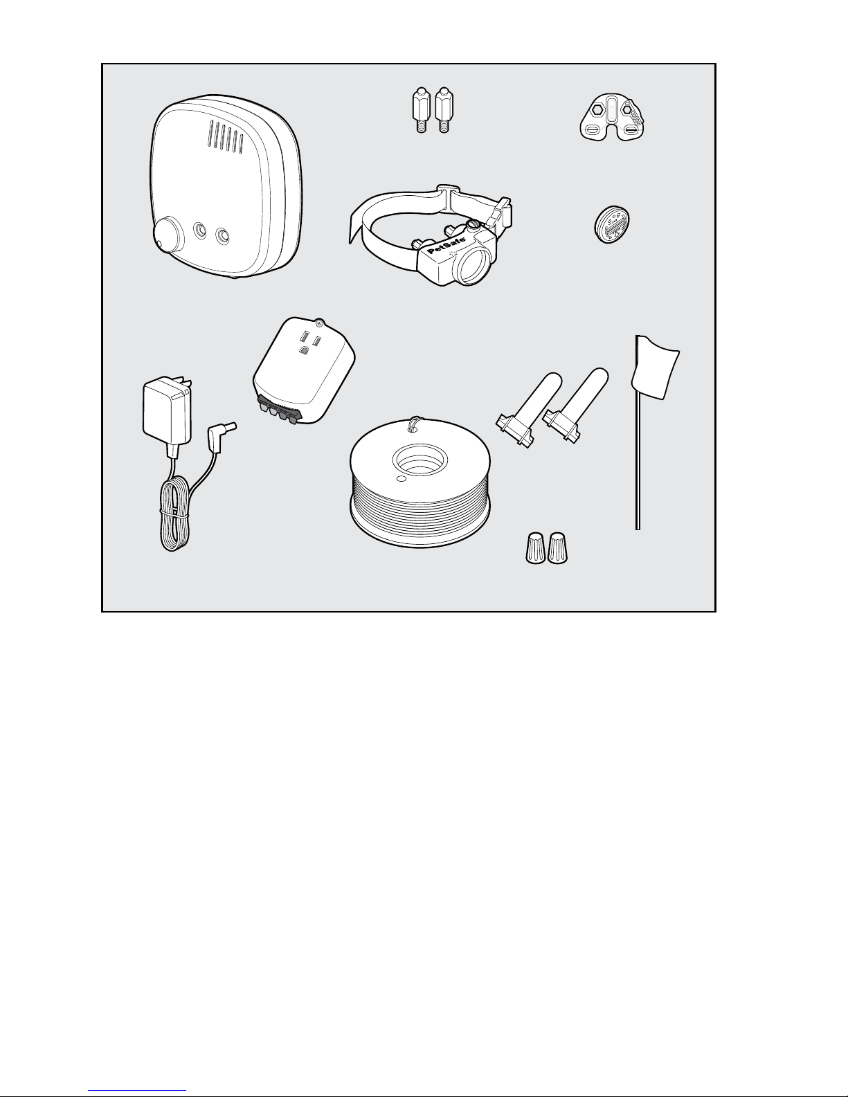
In the Box
You May Also Need
• Additional wire and flags (Part # PIG00-13769)
• Additional wire nuts
• Additional gel-filled capsules
• Drill and mounting hardware
• Tape measure
• Small Phillips screwdriver
• Pliers
• Staple gun
• Scissors
• Lighter
• Shovel or lawn edger
• Wire stripping pliers
• Waterproofing compound (e.g. silicone caulk)
• PVC pipe or hose pipe
• Circular saw with masonry blade
• Non-metallic collar and leash
• Electrical tape
For setup and training help please visit www.petsafe.com.
How the System Works
The PetSafe® Basic In-Ground Fence™ System allows you to safely keep your pet within the boundary you set. We
have safely used static correction for decades and have helped millions of pets live happier, healthier and more
active lives.
The system works by sending a signal through a buried boundary wire (up to 2,000 ft.). Your pet wears a
receiver collar that picks up the signal. It warns your pet with a beep when he enters the warning zone. If your pet
continues to venture out, the collar will issue a safe static correction will be delivered through the contact points to
get his attention until he returns to the pet area. Of course, different pets respond to different levels of correction.
The collar has 4 levels of correction plus a tone-only setting to accommodate any pet. The system has been
proven safe, comfortable and effective for pets over 8 lb. Make sure to go through the training as described in
this product manual before leaving your pet unattended.
Test Light
Tool
Gel-filled
Capsules
Surge
Protector
Receiver Collar with
Short Contact Points
PetSafe
®
RFA-67D-11
Battery
Fence Transmitter
Boundary
Flags
(50)
Power
Adapter
Boundary Wire
(500 ft.)
Wire Nuts
Long
Contact Points
Page 6
6
1-800-732-2677
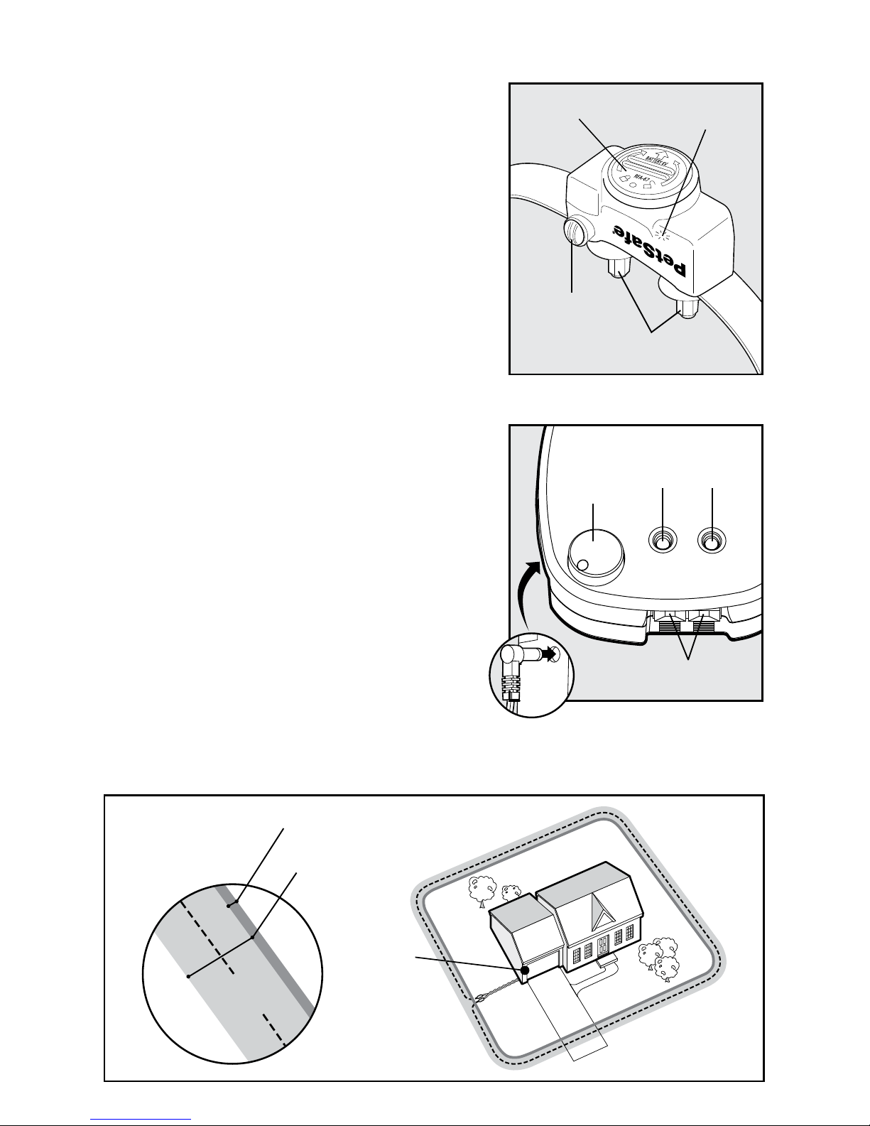
Key Definitions
Fence Transmitter: Transmits the signal through the
boundary wire.
Pet Area: The area within the warning zone where your pet can
roam freely.
Warning Zone: The outer edge of the pet area where your
pet’s receiver collar begins to beep, warning him not to go into
the static correction zone.
Static Correction Zone: The zone beyond the warning zone
where your pet’s receiver collar will emit a static correction,
signaling him to return to the pet area.
Boundary Width: The combination of the warning zone and
the static correction zone.
Surge Protector: Installed with the fence transmitter to protect it
from lightning strikes and power surges.
Receiver Collar: The device that receives the signal from the
boundary wire.
Correction Level Button: Adjusts the level of static correction
your pet receives in the static correction zone.
Receiver Indicator Light: Indicates the level of correction at
which the receiver collar is set. This light also serves as the low
battery indicator.
Contact Points: The contacts through which the receiver collar
delivers the safe static correction when your pet moves into the
static correction zone.
Power Jack: The jack where the power adapter plugs into the
fence transmitter. The fence transmitter is powered by a standard
120-volt outlet.
Boundary Wire Terminals: The terminals where the boundary
wires connect to the fence transmitter in order to complete a
continuous loop.
Loop Indicator Light: The light that indicates that the
boundary wire makes a complete loop, enabling the signal to
be transmitted.
Boundary Width Control: The knob that adjusts the width
of the warning and static correction zones. Note: Adjusting
the knob does not change the level of static correction on the
receiver collar.
Boundary
Width
Control
Power
Light
Power
Jack
Loop
Indicator
Light
Boundary Wire
Terminals
Receiver
Indicator Light
Battery
Contact Points
Correction
Level Button
Receiver Collar
Fence Transmitter
Place
Transmitter
Inside
Pet Area
Static
Correction
Zone
Warning
Zone
Boundary
Width
Page 7
7
petsafe.com
Step 1: Have Your Utilities Marked
1. Call your utility company to have your utility
lines marked. If you have neighbors using
an in-ground pet containment system, you
will want to ask them where the boundary is
located. Place your wire at least 10 ft. away
from it.
2. Large metal objects and wires can cause
interference in unpredictable ways. Make a
plan for how you will work around any large
metal objects, like sheds or existing wires. You
can cross utility lines at a 90° angle (1A).
Underground cables can carry high voltage. Have all underground cables marked
before you dig to bury your wire. In most areas, this is a free service. Avoid these
cables when you dig.
Step 2: Install the Surge Protector and Transmitter
Lightning strikes that occur even several miles away from your installation can create power surges or spikes
which may damage an unprotected system. The surge protector is included to safeguard your In-Ground Fence™
System against surges or spikes that can reach it via your AC power connection and/or boundary wire.
• Do not install, connect or remove your system during a lightning storm. If the
storm is close enough for you to hear thunder, it is close enough to create
hazardous surges.
• Risk of electric shock. Use the fence transmitter and surge protector indoors in a
dry location only.
• Turn off power to the outlet before you install or remove your surge protector.
• Risk of electrical shock or fire. Use the surge protector only with a duplex outlet
with a center screw. Attach the unit with the long screw supplied.
• If possible, do not use an outlet protected with a residual current device (RCD) or
a ground fault circuit interrupter (GFCI). The fence system will function, but in rare
cases, nearby lightning strikes may cause the RCD or GFCI to trip. Without power,
your pet may be vulnerable to escape. You will have to reset the RCD or GFCI to
restore power to the system.
• Do not install the surge protector if there is not at least 30 ft. (10 m) or more of wire
between the electrical outlet and electrical service panel.
• Plug the surge protector into a grounded (3-prong) outlet that is within 5 ft. of the fence
transmitter. ALWAYS use a grounded (3-prong) outlet to ensure maximum protection.
• Do not remove the ground prong from the surge protector plug. Do not use a 3-prong
plug to 2-prong outlet converter. Doing so will make the surge protector ineffective
against surges or spikes.
90°
10 ft.
Buried Cable
Boundary
Wire
10 ft.
1A
Page 8
8
1-800-732-2677
1. Find a place to install the surge protector and
transmitter. There are a few things to consider
when choosing an outlet for your surge protector
and transmitter:
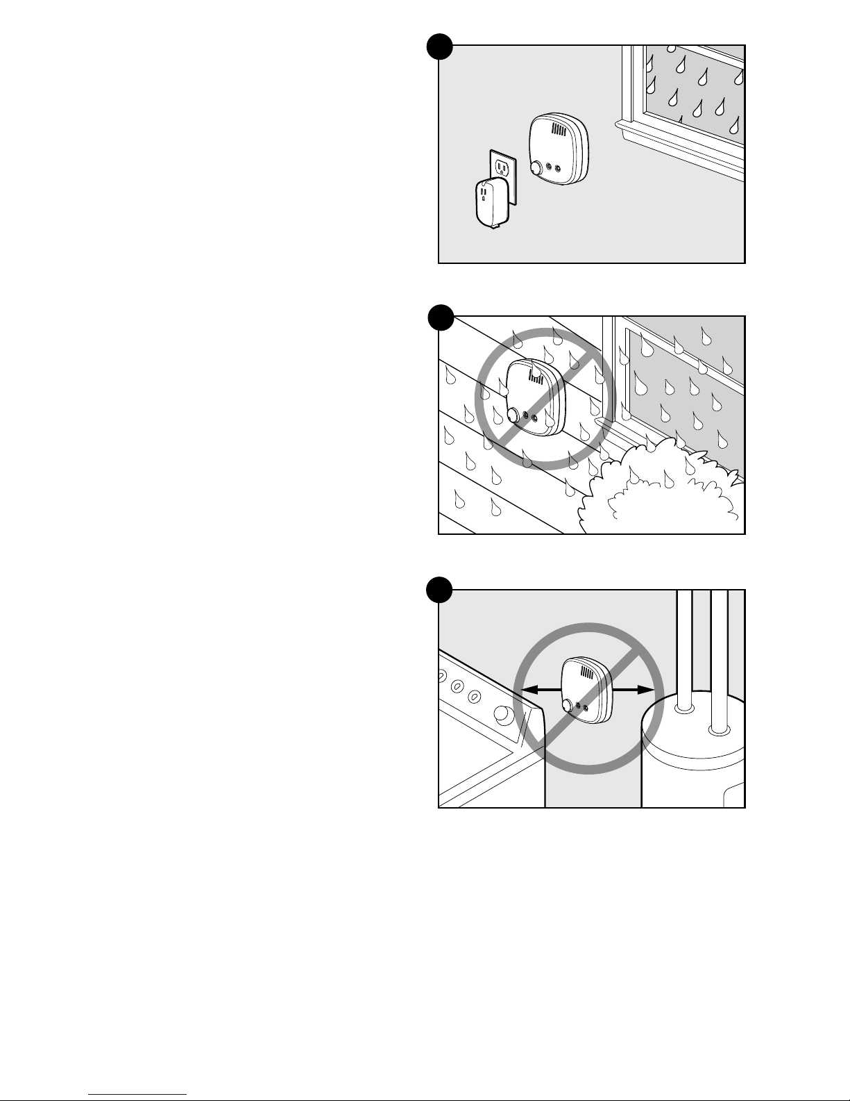
• We recommend using an outlet at least 30 ft. from
the breaker box.
• Both the surge protector and transmitter should be
indoors, in a dry, ventilated and protected area
(2A, 2B).
• The boundary wire must run from the transmitter
and exit the building, so place the transmitter near
a window or a wall that you can drill through (2A).
• The temperatures in that location should not fall
below -10°F/-23°C or above 104°F/40°C.
• Both the surge protector and transmitter should
be at least 3 ft. from large metal objects or
appliances (2C). These items may interfere with the
signal consistency.
• To prevent fires and electrical hazards, install
the fence transmitter in buildings that are in
accordance with state and local electrical codes.
2. Once you have chosen an outlet and before
plugging anything in, go to your breaker box and
turn the power off to that outlet.
3. Then, back at the outlet, remove the center screw
that holds the outlet cover in place.
4. Plug the surge protector into the lower outlet.
5. Using the large screw provided, secure the surge
protector to the outlet.
6. At the breaker box, turn the power back on to
the outlet.
7. Next, you will mount the transmitter somewhere
within 5 ft. of the surge protector.
8. Secure the transmitter to a stationary surface using
appropriate mounting hardware (not included). A
mounting template is included on the back of the
product manual.
9. How to connect all the wires will be explained
later in Step 5.
3 ft.
3 ft.
2A
2B
2C
Page 9
9
petsafe.com
Step 3: Design Your Boundary Zone
Basic Planning Tips
• Always design your layout, position the
boundary wire and test the system as outlined in
this product manual before burying the boundary
wire. You do not want to find out after burying the
wire that there is a problem with your layout or a
loose connection somewhere.
• Sample layouts are provided in this section.
• The boundary wire must start at the fence
transmitter and make a continuous loop
back (3A).
• Always use rounded corners with a minimum 3 ft.
radius to produce a more consistent boundary
(3B). Do not use sharp turns; this will cause gaps
in your boundary.
• Create areas in your yard that allow your pet
to safely cross over the boundary wire without
static correction by twisting the boundary
wires together 10 to 12 times per foot (3C). This
transmission cancels the signal and allows your
pet to safely cross over that area.
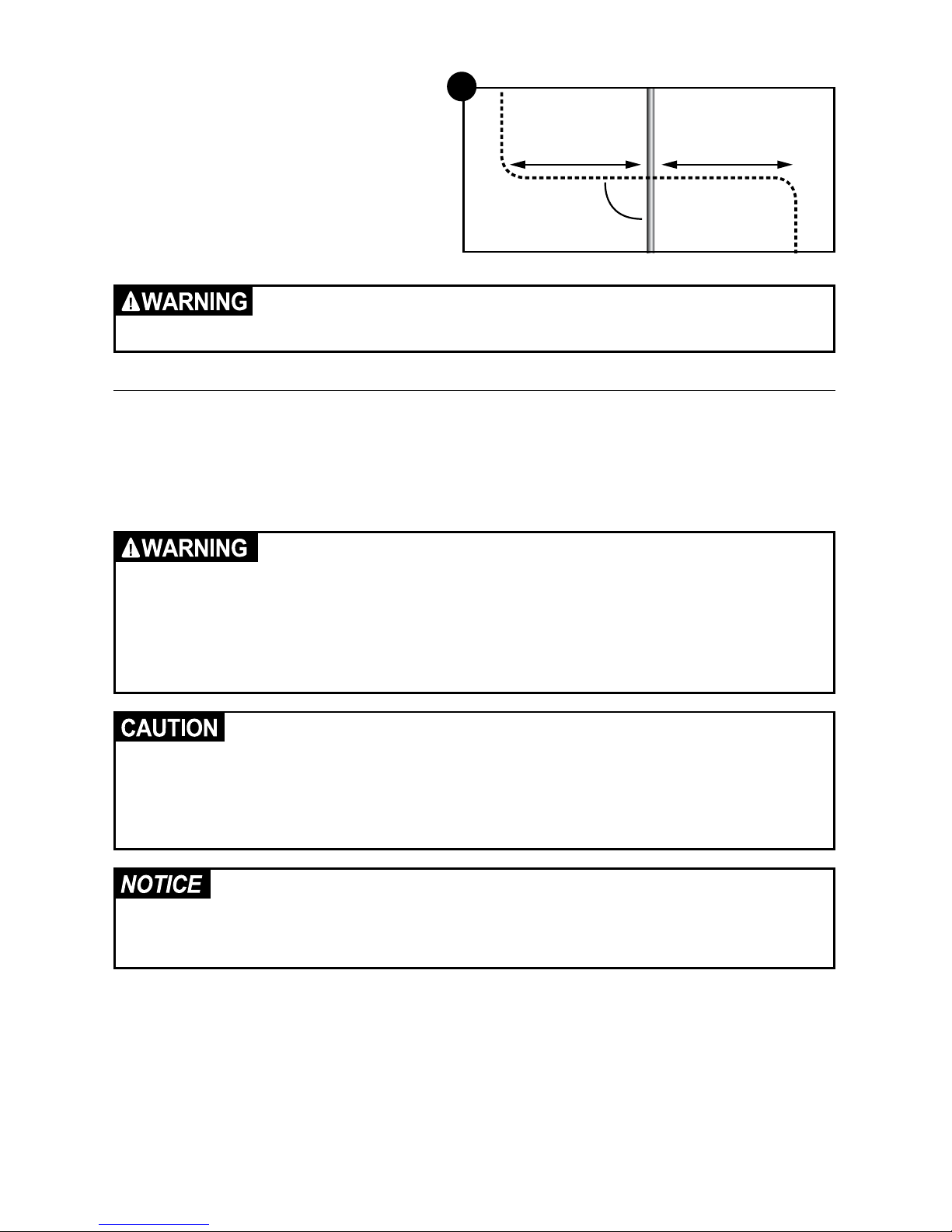
• To properly contain your pet, we recommend
setting a boundary width for the warning
and static correction zones to approximately
12–20 ft. (6 to 10 ft. on each side of the wire).
• Avoid making passageways too narrow for your
pet to move about freely (e.g., along the sides of
a house).
• The receiver collar can be activated inside the
house if the boundary wire runs along the outside
wall of the house. If this occurs, remove your
pet’s receiver collar before bringing him inside,
decrease the range using the boundary width
control knob or consider an alternate layout.
3A
3B
Page 10

10
1-800-732-2677
Single or Double Loop Layout
The containment area can be created by using either a single boundary wire that is placed around the entire
property (3C) or by doubling the boundary wire along the same path (3E).
Single Loop Boundary
• To create a containment area for the entire property
• For exclusion areas around flower gardens, landscaping or pools
With a single loop layout, the boundary wire starts at the fence transmitter, advances out to the yard, continues
all the way around the perimeter of the property and connects back to the fence transmitter. This forms a
boundary zone with a single wire.
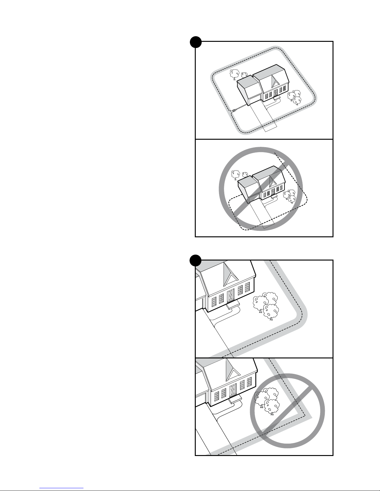
Sample 1 (3C)
Perimeter Loop
The perimeter loop is the most common layout.
This will allow your pet to freely and safely roam
your entire property. It can also protect flower
gardens, pools and landscaping.
Sample 2 (3D)
Full Perimeter Loop Using Existing Fence
This layout allows you to include your existing
fence as part of your layout and keep your pet
from jumping out or digging under your existing
fence. This layout also greatly reduces the
installation time since most of the wire will not
need to be buried.
Run the wire from the fence transmitter to point
A, then to point B and so on (B to C to D to E) all
the way around the entire property until back to
point A again. The wires from point A will then need to be twisted and connected back to the fence transmitter
inside your home.
D
E
A
C
B
3D
3C
Wire
Splices
Place
Transmitter
Inside
Pets Can
Safely Cross
Twisted Wires
Pets Can
Safely Cross
Twisted Wires
10 Twists/ft.
Page 11

11
petsafe.com
Double Loop Boundary
• To section off only one boundary area or one
section of your yard (e.g., front property only, or
waterfront property)
• The 2 parallel sections of the double boundary
wire must be separated by a minimum of
approximately 5 ft. from each other in order to
avoid cancelling out the signal as well as provide
an adequate boundary width (3E)
• A double loop layout requires twice as much wire
as a single loop layout because it doubles back
along the same path
With a double loop layout, the boundary wire starts
at the fence transmitter, advances out to the yard and
continues to form a boundary zone in one section
of your property (e.g., front property only). Then the
wire makes a U-turn back along the same path and
connects back to the fence transmitter. This forms a
boundary zone with a double wire.
Sample 3 (3E)
Front Property or Back Property Only
From the fence transmitter, run the wire to point A, then
to point B and so on (B to C to D to E to F). Next, make
a U-turn and follow your path all the way back to point
G, keeping the wire separated by at least 5 ft. When
you get back to the house (G), make a sharp turn along
the side of the house back to point A. Finally, twist
the wires from point A and connect them back to the
fence transmitter.
Sample 4 (3F)
Front Boundary Only
From the fence transmitter, run the wire to point A, then
to point B. Make a U-turn and follow your path back
to point A, keeping the wire separated by at least 5 ft.
Then twist the wires from point A and connect them
back to the fence transmitter.
Sample 5 (3G)
Waterfront Property
From the fence transmitter, run the wire to point A,
then to point B. Make a U-turn and follow your path
to C, then to D, then to E. Next, make another U-turn
and follow the same path all the way back to point
A, keeping the wire separated by at least 5 ft. Finally,
twist the wires from point A and connect them back to
the fence transmitter.
Sample 6 (3H)
Wire Loop Attached to Existing Fence
This layout allows you to include your existing fence
as part of your layout and keep your pet from jumping
out or digging under your existing fence. It reduces
the amount of wire which will need to be buried.
From the fence transmitter run the wire to point A,
then to point B and so on (B to C to D to E to F). Next,
make a U-turn and follow your path all the way back
to point A, keeping the wire separated by at least
5 ft. Finally, twist the wires from point A back to the
fence transmitter.
A
C
D
E
B
5 ft.
3E
3F
3G
3H
A
C
D
E
F
B
5 ft.
A
B
5 ft.
E
F
B
Place Transmitter Inside
A
A
G
G
D
C
5 ft.
Page 12

12
1-800-732-2677
Step 4: Position, Twist and Splice the Boundary Wire
Once you have designed your layout, the next step is to
position the wire. Hold off on burying the wire until you have
tested the system first.
• Start with one end of the wire at the transmitter, but do
not turn it on yet. Run the wire all the way around your
planned perimeter and back to the transmitter.
Off-limits Areas
• For off-limits areas like gardens, you will need to splice a
section between the main boundary wire and the off-limits
area (3C). This will allow your pet to cross this section
without a correction.
• Also, keep in mind that if you plan to mount the transmitter
to a post or you decide to place it away from the main
boundary location, the boundary wire that runs from
the transmitter out to the main boundary must also be
twisted together.
• Twisting both ends of the wire together 10-12 times
per foot cancels the signal and allows your pet to cross
without receiving a correction. Any crossover areas
must be within the boundary and cannot be along the
perimeter of the boundary (4A). Although not required, it
is recommended that you cut and splice the wire between
each twisted section.
• The fastest way to twist 2 wires is to cut 2 pieces a little
longer than the length you need, twist them, and then
“splice” in that section. Anchor one end of the 2 wires to
something secure (or have a partner hold them), and insert
the other end into a power drill. Pull the wire tight and then
use the drill to slowly twist the wire. Follow the splicing
guide below to learn how to reconnect this twisted portion
back to the main boundary wire.
Splicing Guide
Your system comes with 2 gel-filled splice capsules to ensure
that your splices are waterproof. Contact us if you would like to
purchase more splice capsules.
1. Strip approximately
3
⁄8 in. of insulation off the ends of the wires to be spliced (4B).
2. Insert the stripped ends into the wire nut and twist the wire nut around the wires. Make sure there is no copper
exposed beyond the end of the wire nut.
3. Tie a knot 3 to 4 in. from the wire nut (4C). Ensure that the wire nut is secure on the wire splice.
4. Once you have securely spliced the wires together, open the lid of the gel-filled capsule and insert the wire
nut as deeply as possible into the waterproof gel inside the capsule (4D).
5. Snap the lid of the capsule shut (4E).
Additional Boundary Wire
Extra spools of boundary wire can be purchased in lengths of
500 ft. per spool where you purchased the kit or through the
Customer Care Center.
Note: When adding boundary wire, it must act as a
continuous loop.
The table on the right indicates the approximate length of
boundary wire needed for a square, single loop layout. The
length will vary due to the amount of twisted wire and the
layout used.
}
}
³⁄₈ in. ³⁄₈ in.
4B
4C
4D
4E
4A
Acres Feet of wire required
1
⁄4
415
1
⁄3
480
1
⁄2
590
1 835
2 118 0
5 1870
Page 13

13
petsafe.com
Step 5: Connect the Wires
Now that the boundary wire has been positioned and spliced, the next step is to connect the wire that is running
from outside to the surge protector, and then to the transmitter. Make sure the boundary wire is not cut off or
pinched by a window, door, or garage door, as this can damage it over time.
• Do not install, connect or remove your system during a lightning storm. If the storm is
close enough for you to hear thunder, it is close enough to create hazardous surges.
• Risk of electric shock. Use the fence transmitter and surge protector indoors in a dry
location only.
• Turn off power to the outlet before you install or remove your surge protector.
• Risk of electrical shock or fire. Use the surge protector only with a duplex outlet with
a center screw. Attach the unit with the long screw supplied.
• If possible, do not use an outlet protected with a residual current device (RCD) or a
ground fault circuit interrupter (GFCI). The fence system will function, but in rare cases,
nearby lightning strikes may cause the RCD or GFCI to trip. Without power, your pet
may be vulnerable to escape. You will have to reset the RCD or GFCI to restore power to
the system.
• Do not install the surge protector if there is not at least 30 ft. (10 m) or more of wire
between the electrical outlet and electrical service panel.
• Plug the surge protector into a grounded (3-prong) outlet that is within 5 ft. of the fence
transmitter. ALWAYS use a grounded (3-prong) outlet to ensure maximum protection.
• Do not remove the ground prong from the surge protector plug. Do not use a 3-prong plug
to 2-prong outlet converter. Doing so will make the surge protector ineffective against
surges or spikes.
1. Take the boundary wire that is running
from outside and strip 3⁄8 in. of insulation
from the ends (5A).
2. Insert the stripped ends into the 2 left
red connector holes on the bottom of
the surge protector labeled “Loop”
(5B). There should be 1 wire in each
connector hole. Press the plastic tab,
insert the wires and release the tab.
Make sure the wires do not touch each
other at the terminals.
3. Next, measure and cut 2 lengths of
wire to connect the surge protector
to the fence transmitter. Strip 3⁄8 in. of
insulation from the ends. Twist the 2
lengths together, with at least 10 to 12
twists per foot, so the wires will not send
out a signal.
4. Insert the ends of the twisted transmitter
wires into the right 2 black connectors
at the bottom of the surge protector
labeled “Transmitter”.
5. Press the red plastic tabs on the fence
transmitter and insert the opposite ends of the twisted wire into the boundary wire terminals.
6. Turn the boundary width control knob to 10. This will set the boundary width at the maximum width.
7. Plug in the transmitter power adapter to the outlet on the front of the surge protector. You are now connected (5C).
8. The power light and loop indicator lights should come on. If this does not happen, see the
“Troubleshooting” section.
Verify that the boundary loop and transmitter wires connect to the proper surge protector
terminals. Reversed connections will result in an increased risk of surge related damage.
Boundary
Wire
Transmitter
Wire
³⁄₈ in.
LOOP TRANSMITTER
BOUCLE ÉMETTEUR
Push Tabs
Down to
Insert Wire
5A
5C
5B
Page 14

14
1-800-732-2677
Step 6: Prepare the Receiver Collar
There are two sets of contact points that can be used on your receiver collar. Your receiver collar comes with the
short contact points installed. The longer contact points should be used on dogs with long hair. Tighten the contact
points using test light tool one-half turn beyond finger tight. Check the tightness weekly.
Insert and Remove the Battery
Note: Do not install the battery while the receiver collar is on your pet.
This receiver collar utilizes a replaceable PetSafe
®
battery (RFA-67D-11).
This unique battery is designed to make battery replacement easier and
increase water protection.
To insert the battery, align the symbols on the battery (arrow) and receiver
collar (triangle). Use the edge of the test light tool to turn the battery
clockwise until the arrow lines up with the lock symbol on the housing (6A).
To remove the battery, turn the battery counter-clockwise using the edge
of the test light tool (6B). Do not attempt to cut into or pry open the battery.
Be sure to discard the used battery properly. The battery life will vary
depending on how often your pet tests the system and receives a static
correction Check the receiver collar every month to ensure the battery is
working properly.
If the receiver indicator light is flashing every 4 to 5 seconds, battery
replacement is required. Remove the old battery from the receiver collar.
Discharge all power by holding the correction level button down until the
LED light is no longer illuminated. Replace with a new battery.
A replacement PetSafe
®
battery (RFA-67D-11) can be purchased by
contacting the Customer Care Center or by visiting our website at
www.petsafe.com.
Set the Static Correction Level
1. Remove the clear plastic cover with the test light tool to expose the
correction level button (6C).
2. With the battery installed, press the correction level button and
release when the receiver indicator light turns on (6D).
3. The receiver indicator light will emit a series of flashes representing
the static correction level (e.g., 4 red flashes means level 4).
4. Increase the static correction level by pressing and releasing the
correction level button within 5 seconds of the previous series
of flashes.
5. After setting the static correction level, replace the cover to protect the
correction level button.
The static correction levels increase in strength from 2 to 5, with level 1
being tone only (no correction), and level 5 being the maximum setting.
Pressing the correction level button while the receiver collar is on level 5
will cause the receiver collar to revert to level 1. Refer to the function and
response table to choose the static correction level that best fits your pet.
The receiver collar is equipped to automatically increase the level of static
correction the longer your pet remains in the static correction zone if the
collar is set at level 2 or above.
The receiver indicator light acts as a low battery indicator, flashing every 4
to 5 seconds when replacement is required.
6C
6D
6A
6B
Page 15

15
petsafe.com
Function and Response Table
Indicator Light Static Correction Level Receiver Collar Function
1 red flash 1 None—tone only
2 red flashes 2 Low correction
3 red flashes 3 Medium correction
4 red flashes 4 Medium-high correction
5 red flashes 5 High correction
Flashes once every
4 to 5 seconds
– Indicates low battery
Anti-Linger Prevention
The anti-linger prevention feature keeps your pet from staying in the warning zone for long periods of time and
draining the receiver collar battery. Your pet will hear a warning tone when he reaches the warning zone. If your
pet does not return to the pet area after 2 seconds, he will receive a continuous static correction until he returns to
the pet area.
Run-Through Prevention
This system includes a unique run-through prevention feature so that your pet cannot “run through” the pet area
without receiving an increased level of static correction. The receiver collar automatically increases the static
correction when your pet continues more than 20% of the way through the pet fencing boundary width. For
example, if the signal is detected 10 ft. from the wire and your pet enters the static correction zone, this feature
is activated when he is approximately 8 ft. from the boundary wire. Your pet will then receive a static correction
that is at an increased level corresponding to the static correction level setting on the receiver collar. The receiver
collar is equipped to automatically increase the level of static correction the longer your pet remains in the static
correction zone if the collar is set at level 2 or above. The run-through prevention sound is an intermittent tone.
Over-Correction Protection
In the unlikely event that your pet “freezes” in the static correction zone, this feature limits the static correction
duration to a maximum of 15 seconds. After 15 seconds, the static correction will stop and the green indicator
light will stay on for 10 seconds. The receiver collar remains locked out until your pet leaves the static
correction zone.
Page 16

16
1-800-732-2677
Step 7: Set the Boundary Width and Test the Receiver Collar
With the boundary wire in place and properly connected, it is time to set the boundary width and test the system.
Always remove your pet’s receiver collar before performing any transmitter testing or
adjustments. This will prevent unintended static corrections.
Note: The receiver collar is waterproof, which can make the
tone hard to hear.
The flashing test light, when held to the contact points, indicates
that the receiver collar is delivering static correction. To best
utilize the automatic run-through prevention feature, the
containment boundary width should extend at least 6 to 10 ft.
won each side of the boundary wire (total boundary width of
12 to 20 ft.).
1. Apply power to the fence transmitter with the supplied
power adapter.
2. The boundary width is adjusted by using the transmitter’s
boundary width control knob. Turn the knob counter
clockwise until the loop indicator light is no longer lit. Turn
the knob clockwise and increase by 2 numbers. The light
should turn on.
3. To identify the warning and static correction zones make
sure the static correction on the receiver collar is set at
level 5.
4. Test the boundary width of the system by selecting a section of
straight boundary wire that is at least 50 ft. long. Start inside
the center of the pet area.
5. Place the test light tool contacts (7A) against the receiver
collar contact points (7B). Hold the receiver collar at your
pet’s neck height (7C) with the contact points pointing up and
the PetSafe
®
logo facing the boundary wire. Slowly walk
toward the boundary wire until you hear the warning tone
(7D). When you hear the warning tone, you have identified
the boundary width distance (static correction zone).
6. 2 seconds after the warning tone, the test light will begin
to flash. This flashing light can aid you in identifying the
boundary width if you have difficulty hearing the tone. To
prevent the receiver collar from going into over-correction
protection mode, walk back into the pet area until the toning
stops.
If the receiver collar does not tone at the desired
range, adjust the boundary width control knob to obtain the
desired range.
Test Light Contacts
7A
7B
7C
Boundary
Wire
7D
Page 17

17
petsafe.com
7. Turning the boundary width control knob clockwise
increases the boundary width, while turning it counter
clockwise decreases
it (7E). Repeat this activity as
needed until the receiver collar tones between 6 to
10 ft. from the boundary wire. If using a double loop
layout, you may need to increase the separation of
the boundary wire and/or increase the size of the
boundary width to achieve the desired range.
8. Test the boundary width in a number of different
locations around the pet area until you are satisfied
that the system is functioning properly.
9. Next, walk all around the pet area (7F) to ensure there
are no areas where the receiver collar may activate
from signals coupled onto buried wires or cables. Test
the collar in and around the inside of the house as
well. As mentioned, cable and wires from cable TV,
electrical or telephone lines may conduct pet fencing
signals inside and outside the house that can activate
the pet’s collar accidentally. While rare, if this occurs,
your boundary wire is probably too close to these
outside lines and should be moved or modified as
shown in figure1A .
10. To test the run-through prevention feature, walk
towards the boundary wire. The receiver collar should
tone and the test light should flash brighter as you
enter the run through area (7G). If you are satisfied
that your system is functioning properly, you are ready
to start burying the boundary wire. If the receiver
collar did not tone or the test light did not flash, see the
troubleshooting section.
Boundary Wire
Pet Area
7F
7G
5
2 8
4
10
3
9
1
7
0
6
5
2 8
4
10
3
9
1
7
0
6
7E
Page 18

18
1-800-732-2677
Step 8: Bury the Boundary Wire
Underground cables can carry high voltage. Have all underground cables
marked before you dig to bury your wire. In most areas, this is a free
service. Avoid these cables when you dig.
Before you begin installing the boundary wire, unplug the fence transmitter.
It is recommended to bury the boundary wire to protect it and prevent disabling the system.
1. Cut a trench 1 to 3 in. deep along your planned boundary. It only needs to be as wide as the wire.
Quick Tip: Lawn trenchers, which you can often rent from a local hardware store, work great and make for
a quick job. You can also use a flat shovel, like a
trenching shovel.
2. Place the boundary wire into the trench
maintaining some slack to allow it to expand
and contract with temperature variations.
3. Use a blunt tool such as a wooden paint stick
to push the boundary wire into the trench.
Be careful not to damage the boundary
wire insulation.
Utilizing an Existing Fence
The boundary wire can be attached to a chain
link fence, split rail fence or a wooden privacy
fence. The boundary wire can be attached
as high as needed. However, make sure the
boundary width is set at a high enough range for
your pet to receive the signal.
Chain Link Fence (8A):
Weave the boundary wire through the links or
use plastic quick ties.
• Wooden Split Rail or Privacy Fence (8A):
Use staples to attach the boundary wire.
Avoid puncturing the insulation of the
boundary wire.
• Double Loop with an Existing Fence:
Run the boundary wire on top of the fence
and return it on the bottom of the fence to
get the 5 ft. separation that is needed.
• Gate (Single Loop) (8B):
Bury the boundary wire in the ground across
the gate opening.
Note: The signal is still active across the
gate. Your pet cannot pass through an
open gate.
• Gate (Double Loop) (8B):
Bury both boundary wires across the gate
opening while keeping them 5 ft. apart.
Single Loop
Double Loop
5 ft. 5 ft.
8B
8A
Weave Wire Into Fence
Staple Wire Into Fence
Page 19

19
petsafe.com
Follow all safety instructions for your power tools. Be sure to always wear your
safety goggles.
Cross Hard Surfaces
(driveways, sidewalks, etc.)
• Concrete Driveway or Sidewalk (8C):
Place the boundary wire in a convenient
expansion joint or create a groove using a
circular saw and masonry blade. Place the
boundary wire in the groove and cover with
an appropriate waterproofing compound.
For best results, brush away dirt or other
debris before patching.
• Gravel or Dirt Driveway (8D):
Place the boundary wire in a PVC pipe or
water hose to protect the boundary wire
before burying.
Step 9: Place the Boundary Flags
The boundary flags are visual reminders for your pet of
where the warning zone is located.
1. Place the test light contacts on the contact points. Hold
the receiver collar at the height of your pet’s neck (9A).
2. Walk towards the warning zone until the receiver
collar beeps (9B).
3. Place the boundary flag in the ground along the
boundary wire
(9C).
4. Walk back into the pet area until the beeping stops.
5. Repeat this process along the warning zone until it is
marked with boundary flags every 10 ft.
(9D)
.
Note: If you cannot hear the beep, refer to the test light
instructions in Step 7. To prevent an unintended correction,
after the boundary flags have been placed, be sure to set
the static correction on the receiver collar back to level 1,
which is tone only.
8C
8D
10 ft.
Boundary
Wire
Boundary
Wire
9A
9B
9C
9D
Page 20

20
1-800-732-2677
Step 10: Fit the Receiver Collar
• Proper fit of the receiver collar is important. A receiver collar worn for too long or
made too tight on the pet’s neck may cause skin damage, ranging from redness to
pressure ulcers; this condition is commonly known as bed sores.
• Avoid leaving the receiver collar on the pet for more than 12 hours per day.
• When possible reposition the receiver collar on the pet’s neck every 1 to 2 hours.
• Regularly check the fit to prevent excessive pressure; follow the instructions in this
product manual.
• You may need to trim the hair in the area of the contact points. However, never shave
the pet’s neck; this may lead to a rash or infection.
• Never connect a leash to the receiver collar. It will cause excessive pressure on the
contact points.
• When using a separate collar and leash for training, do not allow the extra collar to
put pressure on the contact points.
• Wash the pet’s neck area and the contact points of the receiver collar weekly with a
damp cloth.
• Examine the contact area daily for signs of a rash or a sore.
• If a rash or sore is found, discontinue use of the receiver collar until the skin
has healed.
• If the condition persists beyond 48 hours, see your veterinarian.
• For additional information on bed sores and pressure necrosis, please visit
our website.
Important: The proper fit and placement of
your receiver collar is important for effective
training. The contact points must have direct
contact with your pet’s skin on the underside
of his neck. Your receiver collar comes with
the short contact points installed. The longer
contact points should be used on dogs with
long hair.
1. Be sure the receiver collar is turned off
before placing it on your pet. Then with
your pet standing, fit the receiver collar
snugly onto your pet’s neck so that the
contact points make contact with your
pet’s skin on the underside of his neck.
2. Check the tightness of the receiver collar
by inserting one finger between the
end of a contact point and your pet’s
neck. The fit should be snug but not
constricting (10A).
3. Allow your pet to wear the receiver collar
for a few minutes, then check it again.
4. The collar will slip if it is not properly
threaded. The slide buckle prevents the
collar from becoming loose around your
pet’s neck and the ridges must be facing
up (10B).
5. Once you are satisfied with the fit of the
receiver collar, remove it from your pet
and trim it, but make sure to allow room
for growth or a thicker winter coat. Use
a lighter to seal the cut so that it will not
fray (10C).
Slide Buckle
Ridges facing up
10B
10 C
10A
Page 21

21
petsafe.com
Training
• Remember that this system is not a solid barrier. Using it successfully requires that you spend some time
training your pet.
• Finish each training session on a positive note with lots of praise and play. Remove the collar after each
training session.
• While your pet is still learning the boundary, contain him by another means, such as with a pen or a leash.
• Be sure to place the collar on your dog’s neck with the PetSafe® logo facing up.
• If your pet appears to be stressed, slow down the training schedule, add additional days of training or
increase the amount of play time. Common stress signals include pulling on the leash toward the house, ears
tucked or pulled back, tail down or tucked between legs, body lowered, nervous/frantic movement or
stiffening of the pet’s body, lip-licking or yawning.
Day 1
For the first day, start with the collar set to level 1, tone-only. Put a
separate non-metallic collar on your pet’s neck and attach a leash.
With your pet’s favorite treats on hand, allow him to explore the
pet area (11A ). Allow your pet to cross the boundary (11B ) and
hear the tone from the collar, then ask him to come back into the pet
area (11C ) and praise and reward him. Your goal is for your dog
to associate being inside the pet area with rewarding experiences.
Dogs are sensitive. Keep your mood upbeat as dogs can understand
when you are happy or upset. Do 2 or 3 training sessions for about
10-15 minutes each. Do not try to do too much too quickly. More
frequent short sessions are better than less frequent, longer sessions.
Days 2–4
On days 2 through 4, repeat this process, but with the collar set
to level 2—the mildest static correction level. Closely observe your
pet’s behavior while he is in the correction zone (11B), and note
whether or not your dog responds to the correction. Indicators of
a response are looking around in curiosity, flicking of the ears or
scratching at the collar. If he does not respond, check the fit of the
collar to make sure the contact points are making contact with his
skin. If the collar is fit correctly and your dog does not respond, then
move up to the next correction level and repeat the process. Do 2 or
3 training sessions for about 10–15 minutes each. Your goal is for
your dog to consistently choose to stay in the pet area. If necessary,
add in more days of training before moving on to the next step.
Days 5–8
On days 5 through 8, retain the collar settings from the last training
session, but stage some distractions to test your dog’s reliability. The
goal is to have your pet stay within the boundary even with new
temptations. Start with simple temptations and work your way up.
Some examples are:
• Have a family member cross from inside the boundary and
exit it.
• Place a toy outside the boundary.
• Have a friend or neighbor walk another pet outside the
boundary area.
Remember to keep your pet on a leash throughout this process while
he is still learning the boundary. Also, never coax your pet to leave
the pet area.
11 C
11 B
11 A
Page 22

22
1-800-732-2677
Days 9–30
Once your pet consistently respects the boundary
regardless of distractions or temptations, he is ready for
the next step: unleashed supervision (11D). Stay close
by with a leash at hand. Play with your pet for a while
during the first few sessions. If your dog does not try to
cross the boundary, occupy yourself with another task
in the yard, and allow him to freely explore. Continue
watching your pet. If he escapes, remove the collar and
lead him back into the pet area. Start these sessions
at about 15 minutes and gradually work up to an hour
or more.
When your pet proves trustworthy, you can let him out
on his own. Continue to check on him regularly. You
can remove every other boundary flag every 4 days
until all the flags are removed. Save them in case you
move or need to train another pet.
Taking Your Pet Out of the Pet Area
Important: Remove the receiver collar and leave it at home.
Once your pet learns the boundary, he will be reluctant to cross it for
walks or car rides.
Option 1:
Replace the receiver collar with a regular collar. Put your pet in a car
that is within the pet area and drive him out of the pet area.
Option 2:
Replace the receiver collar with a regular collar and leash. Walk your
pet out of the pet area while giving a command such as “OK” at a
specific place along the boundary (the end of your driveway, sidewalk,
etc.). Always leave the pet area from the same spot in your yard with a
leash and your pet will associate leaving the pet area only on a leash,
only at this spot, and only with a person. You may initially need to
convince your pet to leave the pet area with a treat and lots of praise.
Note: You may also carry your pet out of the pet area.
Congratulations!
You have now completed the training program. You are both ready to enjoy more freedom. Just make sure to
continue to check the tightness of the receiver collar and remove it when it is not in use.
11 D
Page 23

23
petsafe.com
System Test
The system test is used to determine the cause of system problems
that have not been addressed elsewhere in this product manual.
You will need a piece of boundary wire greater than 15 ft. long
with 3⁄8 in. of insulation removed from each end to use as a test
loop wire. Make a note of your boundary width dial setting, and
receiver collar setting before beginning the system test.
Follow the steps below to perform the system test:
1. Remove the receiver collar from your pet and make sure a
good battery is installed in the receiver collar.
2. Set the receiver collar static correction to level 5.
3. Disconnect the twisted boundary wire from the boundary wire
terminals on the fence transmitter by pressing the red release
levers on the connector and pulling the wires free.
4. Insert the two ends of the test loop wire into the boundary wire
terminals on the transmitter.
5. Turn the boundary width control knob to 10 and then back
to 5.
6. Place the test light tool contacts on the contact points of the
receiver collar. While holding the receiver collar with the test
light tool in place, approach the wire from the outside loop 2
in. off the ground (12A). Make a mental note of the distance
where the receiver collar activates from the wire.
7. Turn the boundary width control knob to 10 and repeat step
6. The distance where the receiver collar activates should be
greater than the previous result.
8. If more than one receiver collar is used on the system, repeat
the above test on each collar.
9. Interpreting the results:
a. If the power light or the loop indicator light are not both
lit on the fence transmitter for any of the above tests, there
is a problem with the transmitter. Contact the Customer
Care Center.
b. If both the power and loop indicator lights are on, but the
receiver collar does not activate on the test loop wire,
the receiver collar is not working. Contact the Customer
Care Center.
c. If the transmitter power and loop indicator lights are on and
the receiver collar is activating at different distances on the
test loop wire, the problem is most likely in the containment
boundary wire or surge protector. Reconnect the transmitter
wires to the surge protector and connect the test loop to the
surge protector loop terminals (12B). Repeat steps 5-8.
10. Interpreting the results with the surge protector:
a. If both the power and loop indicator lights are on and the
receiver collar is activating at different distances on the test
loop wire, the problem is in the containment boundary wire. Perform the wire break location test.
b. If the loop indicator light is off there is a problem with the surge protector. Contact the Customer Care Center.
11. When the testing is complete, reconnect and verify that the boundary wire is plugged into the loop terminals
on the surge protector and the transmitter is connected to the surge protector.
12. Return the boundary width control knob setting to the position noted earlier.
13. Repeat the boundary width testing from Step 7 on page 16 until you achieve the desired boundary width
between 12 and 20 ft.
Surge Protector Unconnected
Surge Protector Connected
12 A
12 B
Page 24

24
1-800-732-2677
Wire Break Location Test
The following lists identify the common locations where wire breaks occur. Please inspect these areas for signs
of damage.
Wire breaks are commonly found:
• At the wire exit point of the house
• Where the wire enters the ground from the house, usually caused by string trimmers
• Where the wires cross sidewalks or driveways, usually caused by edging and string trimmers
• Around landscaping and flower beds, usually caused by digging, or working up the soil
• In aerated lawns
• At wire splices where gel-filled capsules have not been installed
• At wire splices without reinforcement knots
If you still cannot find the break in the boundary wire, there are 2 options for locating it:
Option 1: It is recommended to contact the Customer Care Center to purchase a Wire Break Locator. The Wire
Break Locator detects full breaks, not partial breaks.
Option 2: Follow the procedure below:
1. Unplug the fence transmitter.
2. Connect both ends of your twisted boundary wire to one loop terminal on the surge protector.
3. Measure and cut a test wire which is half the length of your total boundary wire footage.
4. Connect one end of test wire to the other loop terminal on the surge protector.
5. Locate the halfway point of your boundary and cut the boundary wire.
6. Splice the other end of the test wire to either side of your boundary wire where you cut it in half.
7. Plug in the fence transmitter and check the loop indicator light. If the loop indicator light is on, you can
assume the break is in the other half of the boundary wire.
8. If the loop Indicator light did not come on, you may assume there is a break in this portion of the boundary
wire. However, there is a small chance of having more than one break in your system. Be sure to check both
halves of your entire loop.
9. Replace the damaged boundary wire with new boundary wire.
10. Reconnect the boundary wire to the surge protector.
11. Check the loop indicator light. If the loop indicator light is on, test the system with the receiver collar.
Page 25

25
petsafe.com
Troubleshooting
The receiver collar is not
beeping or correcting.
• Check the battery to make sure it is installed properly.
• Check that both lights are lit on the fence transmitter. If not, perform
the “System Test.”
The receiver collar is beeping,
but the pet is not responding to
the static correction.
• Test the receiver collar with the test light by walking toward
the boundary wire. If the test light flashes, adjust the fit of the
receiver collar.
• Trim your pet’s fur where the contact points touch the neck and/or
switch to the longer contact points.
• The contact points must be in contact with pet’s skin.
• Increase the static correction level.
• Repeat the training steps to reinforce training.
• Purchase a stronger receiver collar by contacting the
Customer Care Center.
The receiver collar has to be
held on top of the boundary
wire to activate.
• Replace the battery.
• Adjust the boundary width control knob clockwise to increase the
distance from the boundary wire that the receiver collar activates.
• If using a double loop layout, make sure the boundary wires are
separated at least 5 ft.
• If the receiver collar still has to be held on top of the boundary wire,
perform the “System Test.”
The receiver collar activates
inside the house.
• Turn the boundary width control knob counter clockwise to
decrease the distance from the boundary wire that the receiver
collar activates.
• Make sure the boundary wire is not running within
15 ft. of the house. The signal can transmit through the
walls of your house.
• Make sure the boundary wires are twisted from the boundary to
the fence transmitter.
The receiver LED indicator light
is flashing every 4 to 5 seconds
and I have just installed a
new battery.
• To reset the low battery indicator, remove the battery from the
receiver collar. Discharge all power by holding the correction
level button down until the LED is no longer illuminated. Reinstall
the battery.
I have an inconsistent signal. • Make sure the fence transmitter is at least 3 ft. from large metal
objects or appliances.
• Make sure all boundary wire turns are gradual.
• Make sure the boundary wire is not running parallel to or within
10 ft. of electrical wires, neighboring containment systems,
telephone wires, television or antenna cables, or satellite dishes.
• If a neighboring containment system may be causing an inconsistent
signal, move the boundary wire farther away from the neighboring
containment system.
Page 26

26
1-800-732-2677
The power and loop indicator
lights are off.
• Check that the power adapter is plugged into the fence transmitter.
• Check that the power adapter is plugged in properly.
• If the system is plugged into a RCD or GFCI outlet, check to see
if the circuit has been tripped. Reset the RCD or GFCI circuit
if required.
• Verify that the outlet is working properly by plugging in a known
working item such as a radio.
• Try plugging the fence transmitter into another 120-volt outlet.
• If the lights still do not come on, the fence transmitter and/or power
adapter needs to be replaced. Contact the Customer Care Center.
• If a surge protector is installed, unplug the surge protector and plug
the power adapter directly into the outlet. If the transmitter operates
without the surge protector, contact the Customer Care Center for a
replacement surge protector.
The power light is on and the
loop indicator light is off.
• Check the boundary wire connections at the fence transmitter for
proper connection.
• Check for broken or damaged boundary wires at the outside entry
to the house.
• Perform the “System Test” to determine if the fence transmitter needs
to be replaced.
• If the fence transmitter is functioning properly, you have a break in
your boundary wire (see the “Wire Break Location Test” section).
Terms of Use and Limitation of Liability
1. Terms of Use
The use of this product is subject to your acceptance without modification of the terms, conditions and notices
contained with this product. Use of this product implies acceptance of all such terms, conditions, and notices.
If you do not wish to accept these terms, conditions, and notices, please return the product, unused, in its
original packaging and at your own cost and risk to the relevant Customer Care location together with proof
of purchase for a full refund.
2. Proper Use
Proper use includes, without limitation, reviewing the entire product manual and any specific safety
information statements. The specific temperament or size/weight of your pet may not be suitable for this
product. If you are unsure whether this product is appropriate for your pet, please consult your veterinarian
or certified trainer prior to use. For products used with pets where training is desired, Radio Systems
Corporation recommends that these training products are not used if your pet is aggressive and accepts no
liability for determining suitability in individual cases.
3. No Unlawful or Prohibited Use
This product is designed for use with pets only. This product is not intended to harm, injure or provoke. Using
this product in a way that is not intended could result in violation of Federal, State or local laws.
4. Limitation of Liability
In no event shall Radio Systems Corporation or any of its associated companies be liable for (i) any direct,
indirect, punitive, incidental, special or consequential damage and/or (ii) any loss or damages whatsoever
arising out of or connected with the use or misuse of this product. The purchaser assumes all risks and liability
from the use of this product to the fullest extent permissible by law.
5. Modification of Terms and Conditions
Radio Systems Corporation reserves the right to change the terms, conditions and notices governing this
product from time to time. If such changes have been notified to you prior to your use of this product, they
shall be binding on you as if incorporated herein.
Page 27

27
petsafe.com
Compliance
FCC
This device complies with part 15 of the FCC Rules. Operation is subject to the following two conditions: (1) This
device may not cause harmful interference, and (2) this device must accept any interference received, including
interference that may cause undesired operation.
Note: This equipment has been tested and found to comply with the limits for a Class B digital device, pursuant to
part 15 of the FCC Rules. These limits are designed to provide reasonable protection against harmful interference
in a residential installation. This equipment generates, uses, and can radiate radio frequency energy and, if not
installed and used in accordance with the instructions, may cause harmful interference to radio communications.
However, there is no guarantee that interference will not occur in a specific installation. If interference does
occur to radio or television reception, which can be determined by turning the equipment off and on, the user is
encouraged to try to correct the interference by one or more of the following measures:
• Reorient or relocate the receiving antenna.
• Increase the separation between the equipment and the receiver.
• Connect the equipment to an outlet on a circuit different from that to which the receiver is connected.
• Contact the Customer Care Center at +1 (800) 732-2677
Caution: Modification or changes to this equipment not expressly approved by Radio Systems Corporation may
void the user’s authority to operate the equipment.
Perchlorate Battery
Perchlorate Material – special handling may apply. See www.dtsc.ca.gov/hazardouswaste/perchlorate.
Battery Disposal
Separate collection of spent batteries is required in many regions; check the regulations in your area before
discarding spent batteries. At the end of the product life, please contact our Customer Care Center to receive
instructions on proper disposal of the unit. Please do not dispose of the unit in household or municipal waste. For a
listing of Customer Care Center telephone numbers in your area, visit our website at www.petsafe.com.
Important Recycling Advice
Please respect the Waste Electrical and Electronic Equipment regulations in your country. This equipment must be
recycled. If you no longer require this equipment, do not place it in the normal municipal waste system. Please
return it to where it was purchased in order that it can be placed in our recycling system. If this is not possible,
please contact the Customer Care Centre for further information.
Warranty
One Year Non-Transferable Limited Warranty
This Product has the benefit of a limited manufacturer’s warranty. Complete details of the warranty applicable
to this Product and its terms can be found at www.petsafe.com and/or are available by contacting your local
Customer Care Center.
Page 28

Drill here
Drill here
Radio Systems Corporation
10427 PetSafe Way
Knoxville, TN 37932 USA
+1 (800) 732-2677
petsafe.com
For a list of patents protecting this product,
please visit www.radiosystemscorporation.com/patents
J400-1751/1
©
2018 Radio Systems Corporation
Mounting Template
3 in.
 Loading...