

Page 1
Corporate Ofce: PerTronix Inc. 440 E. Arrow Highway, San Dimas, California 91773 * Phone 909.599.5955 • FAX 909.599.6424
Installation Instructions
and Warranty Information
Chevrolet & GMC Trucks with 4.3 V6
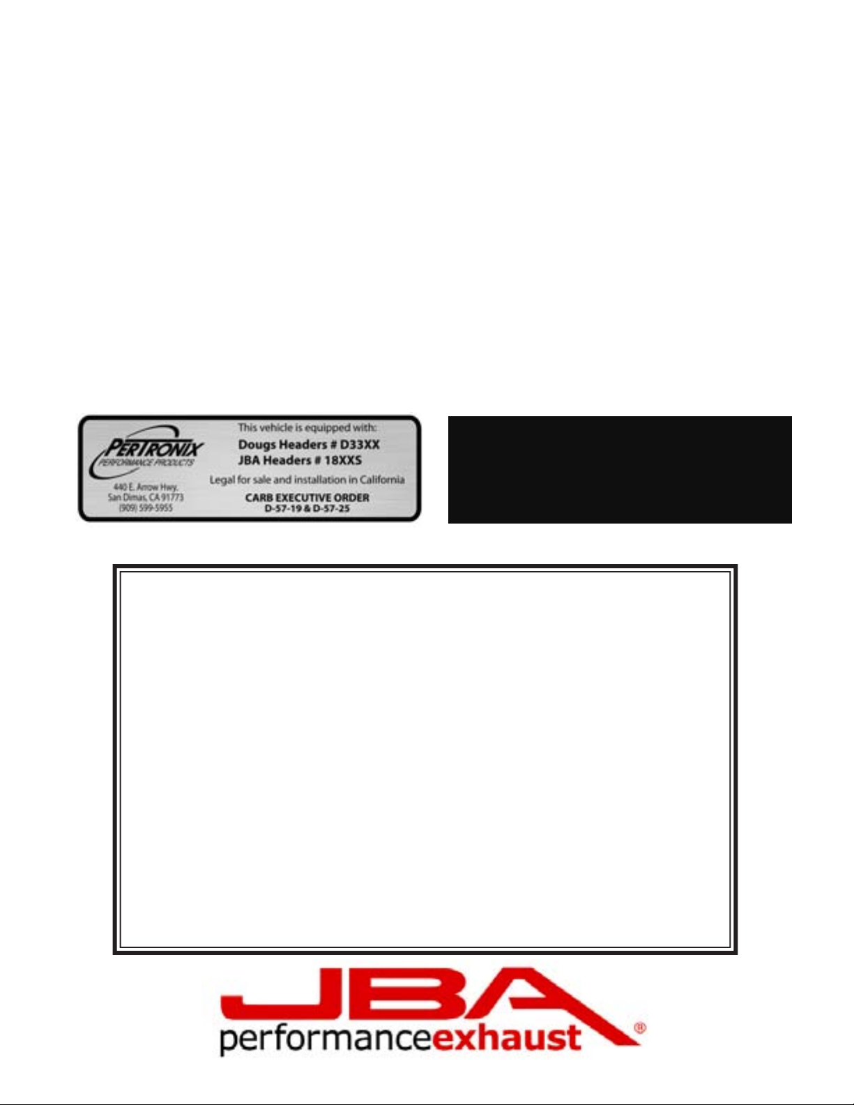
1840S 1988-95 C/K w/o AIR Inj.
1841S 1988-95 C/K w AIR Inj.
Read all instructions carefully before attempting installation.
Rev. 2 2-28-13 DSL
Page 2

PerTronix© thanks you for choosing JBA HEADERS, the best fitting, highest quality header on the market. In order to realize the full potential of our good fit, please read and understand these instructions completely prior to starting work.
Check to make sure you received the proper parts for your application. The header number will be stamped on the engine
flange. If you are unsure you have received the proper parts call before you start work.
Be sure to work safe! Whenever you work under the vehicle be sure that it is located on level, solid ground and is supported
by adequate safety stands! Remember: Hot asphalt will not support most jack stands! Many factors affect the installation of
headers, some of which are broken or aftermarket motor mounts, accidents that impact the configuration of the frame, and/or
the installation of different engines or aftermarket cylinder heads.
Attention Customers breaking in new engines: Due to the extreme heat generated during the break-in process, the appearance
of the ceramic coating may be altered in certain areas. The protection characteristics and thermal barrier properties of the
coating is never compromised. It is recommended that a cast iron manifold or old set of headers be used for this process.
Notice: The coating of these headers can be marred or scratched during installation. If the header needs to be returned and is
damaged, you will be charged for recoat.
JBA uses sealing beads on all its headers. We have found that when installed correctly, the raised bead around each port increases the
pressure exerted on the gasket directly adjacent to the port and effectively prevents leaking gaskets. It is normal for the flange to be
raised off the cylinder head the thickness of the sealing bead. It is important when installing the header, to install all bolts loosely, then
tighten evenly to ensure the flat installation of the flange. The torque sequence from one flange to another will vary, but generally
every bolt on a header should be first fit snug, starting from the inside of the flange working out, alternating from top to bottom so that
the bolt connects the flange to the manifold to the point where they barely touch. Second, using the same inside-out pattern, tighten
each bolt until finished. This method will help prevent leakage and will give the user the best possible performance out of their pair of
headers.
1. Place vehicle in a location where the floor is solid and flat, with adequate lighting. Do not attempt to work on a hot engine. Heat
causes metal to expand and makes removal of fasteners difficult at best. Disconnect the battery cables from the battery. Raise the front
of the vehicle to obtain adequate access to the bottom exhaust manifold flanges. Use large-base jack stands to support the vehicle. Do
not rely on the jack! Block the tires to prevent the vehicle from rolling off the jack stands.
2. Begin with the driver ’s side. (It is the more difficult of the two sides) Spray WD-40 or some type of penetrating oil on all accessible
fasteners and ttings before attempting to remove them. From the bottom side, unbolt the spring-loaded bottom ange nuts (where the
manifold connects to the exhaust system). The stock nuts are intentionally deformed to prevent them from prematurely loosening. This
also makes removal difficult. Apply as much torque as necessary to remove the nuts. The nuts may not turn and the stud may begin to
unthread from the manifold. This is a problem because the studs have shoulders, which will not pull through the exhaust flange. If the
stud comes loose, reverse your wrench and tighten the stud back into the manifold solidly. Try again to remove the nuts. If the nuts are
still jammed on, apply heat to the nut with an acetylene torch. Try again to remove the nuts. If all else fails cut the nuts off. The Headers are supplied with new bolts and nuts for reinstallation.
3. On the topside: Unbolt the spark plug wire looms from the cylinder heads. Do not skip
this step. Otherwise the spark plug looms will hold the head flange out, away from the head,
preventing the headers from sealing. Disconnect the spark plug wires by grasping and gently
twisting the spark plug wire boots. Do not pull on the wires. Set the wires and looms up out
of the way. Brush or blow away any debris, which may have collected around the manifolds
and spark plugs. This will help prevent foreign matter from entering the combustion chambers when the manifolds are removed. Removal of the spark plugs is not necessary, but it
may avoid accidental spark plug breakage.
4. The power steering pump must be freed from its bracketry in order to remove the driver ’s side manifold. This is due to the design
of the power steering pump/alternator bracketry. The steel bracket is fastened to the exhaust manifold studs on both sides of the front
exhaust port. The studs cannot be removed until the bracket is pulled outward from the engine. The bracket cannot be pulled outward
until the power steering pump is removed from the aluminum bracket. Besides, the steel bracket needs to be removed to modify it
anyway!
Page 3

5. Remove the top half of the fan shroud. Remove the serpentine belt. Using a pulley remover
(Snap-On CJ117A or equivalent), remove the power steering pump pulley. The three bolts on
the front of the power steering pump may now be removed. Remove the bolt going from the
black steel bracket into the back of the alternator. Remove the nuts holding the black steel
bracket to the head on both sides of the number one exhaust port. The black steel bracket is
still attached to the back of the power steering pump. The pump assembly should be loose
enough to wiggle outward from the engine such that the remaining two nuts holding the steel
bracket to the back of the pump can be removed. The black steel bracket should now be free.
6. Remove the steel bracket. Using a hack saw, abrasive cut-off wheel, or band saw, cut the
bracket as shown in gure 2.Grind the bracket for clearance as indicated in Fig 2.Clean up the
edges with a file or sander and repaint.
7. If equipped, remove the O2 sensor from the rear of the Manifold. (Use and open-end wrench
or special O2 sensor socket.) Remove the 4 bolts and 2 studs holding the manifold to the head.
Save one of the studs fastening the manifold to the #1 exhaust port. Using a small wire brush
or other instrument, remove any carbon deposits left on the exhaust flange-mating surface of
the head. Thoroughly clean the surface with solvent or another cleaner. Remove the doughnutshaped gasket from the lower flange (where the manifold bolts to the exhaust system.) The
headers use a steel dome in place of this gasket. Remove any excess carbon deposits from the
lower flange.
8. If your vehicle does not have an O2 sensor in the rear of the manifold, use the supplied plug to seal the O2 sensor fitting in the collector of the driver’s side header. Use
a sealant as described below on the threads of the plug. (Optional: Prepare the header
bolts by applying anti-seize to the threads.) (Small head 3/8” x 1” bolts &lock-washers
included.). On the driver’s side use 5 of the 3/8” x 1” bolts supplied. Reuse one of the
studs in the front hole of the #1 port. Apply a thin coating of sealant to the collector
dome where it mates to the lower flange. Permatex Ultra-Copper High-Temp Sealant is
recommended. DO NOT use a sealant that is not designed to be used with O2 sensors.
(Also note that if excessive sealant is applied, clumps may fall into the exhaust system
and clog the Catalytic Converter.) Bolt the header to the head. Use the supplied bolts and
lock washers on the rear 5 bolts. Do not use a lock washer on the front hole where the
stud is being re-used. Use the supplied 1” tubular spacer between the header flange and
the stud shoulder on the front hole. See g.3. Torque all 6 fasteners to factory specications (30-35 ft./lbs.).
9. Using the supplied fasteners, bolt the Header to the bottom flange. The nuts are jam nuts. Therefore they will not spin freely. This is
normal. Torque to 30-35 ft./lbs.
10. To reinstall the spark plug wire looms, use the supplied 1/2” tubular spacer and 1/4” bolt. The spark plug wire loom will now sit
outward of the header flange rather than against the head. If equipped, reinstall the O2 sensor.
11. Re-install the modied black steel bracket in the reverse order of removal. First, fasten the bracket to the rear of the power steering
pump. Maneuver the power steering pump back into its original position. The steel bracket will now attach to the head with the single
stud in the front hole of the #1 exhaust port. Attach the bracket to the head via the stud in the front hole of the #1 exhaust port. Fasten
the steel bracket to the back of the alternator. Install the three bolts back through the front of the power steering pump. Reinstall the
pulley using the pulley installer. (Thread the mandrel into the pump shaft. Then press the pulley back onto the pump shaft.) Re-install
the serpentine belt. Re-assemble the fan shroud.
12. The Passenger Side: Unbolt the manifold from the exhaust system from under the vehicle as on the driver ’s side. Remove the
dipstick. Disconnect the spark plug wires from the spark plugs. Unbolt the Spark Plug wire looms and put them up out of the way. The
dipstick tube is bolted to the head via the forward spark plug wire loom bolt. With the bolt removed, the dipstick tube can be removed
by gently wiggling the tube while pulling upward. (The bottom of the tube is pressed into a receptacle in the engine.) Remove the
exible hot air tube attached to the sheet metal heat stove. (See Figure 4.) Unbolt the manifold from the head and remove. As with
the driver ’s side, clean the head flange and lower flange where the header will attach to the exhaust system. Remember to remove the
doughnut-shaped gasket.
Page 4
13. As with the driver’s side, apply anti-seize to the bolts, apply silicone to the dome flange, and bolt the headers to the head and the
exhaust system. Reattach the spark plug looms in the same manner as the driver’s side.
14. If retaining the heat riser, clamp the supplied heat riser adapter to the header using the supplied hose clamp. Shorten flexible heat
riser tube to fit (about 3-1/2 inches). Take care not to cut the tube too short.
15. Recheck everything!
16. Start engine and let it warm up. Check for leaks. Shut engine off and let it cool down. Check to make sure all fasteners are tight.
17. Periodically check and retighten the header bolts.
Parts List:
(1) Driver’s Side Header Assembly (6) Collector Bolts, Nuts &Washers.
(1) Passenger’s Side Header Assembly (4) 1/4”I.D. x 1/2” long spacer
(11) 3/8” x 1”header bolts & lock washers (4) 1/4”x 1” bolts
(2) Header gaskets (1) Heat Riser Tube Adapter.
(1) 3/8” I.D. x 1” long spacer (1) Plug for the O2 sensor fitting
(2) 90 degree spark plug boots (2) Spark plug wire terminals
LIMITED ONE YEAR WARRANTY
All JBA HEADERS and exhaust products are guaranteed, to the original purchaser, to be free of defects in materials and workmanship for one year. This warranty
covers the replacement or repair of the product only and does not cover the cost
of removal and installation, customer applied aftermarket coatings or any discolor-
ation or corrosion of nished surfaces.
Damage or product failure resulting from collision, improper installation, off-road
use, road hazards, the use of exhaust insulating wrap or like products or rust occurring after installation, is not covered by the warranty. The warranty extends only
to the original purchaser.
Should a part become defective it should be returned to the original selling retailer
and must be accompanied with the sales receipt. If there is no retailer in your area,
call the factory for a return authorization and return your part prepaid to the factory
for inspection. PerTronix reserves the rights to replace or repair the alleged defective part and return the part freight collect.
Page 5

 Loading...