

Page 1
6-Volt Positive Ground Installation Instructions
For Part Number: 1281P6
CAUTION!!! Before installing, please read the following important information....
1. The Ignitor is designed for 6-Volt positive ground systems.
2. Leaving the ignition “ON” with the engine “OFF” for an extended period could result in permanent damage to
the Ignitor.
3. See Chart on back page for coil recommendations.
4. Eight cylinder engines require a minimum of 0.6 ohms of primary resistance. Do not remove resistors if the
coil primary resistance is less than 0.6 ohms.
5. If your Ignition coil has the recommended primary resistance, remove or bypass all external resistors.
DISASSEMBLY
1. PRIOR TO INSTALLATION TURN IGNITION SWITCH OFF OR DISCONNECT THE BATTERY
2. Remove the distributor cap, and rotor. Do not disconnect spark plug wires. Examine cap and rotor for wear
or damage. Replace as needed.
3. Disconnect the point wire from the negative (-) terminal of the coil.
4. Remove the point wire, point, and condenser from the distributor.
5. The Ignitor does not require any modification to the distributor. Therefore the point, condenser and hardware
can be used as backup.
6. Clean all dirt and excess oil from the breaker plate and point cam.
IGNITOR INSTALLATION
1. Insert the Ignitor black and red wires through the distirbutor housing verifying the grommet is seated
properly.
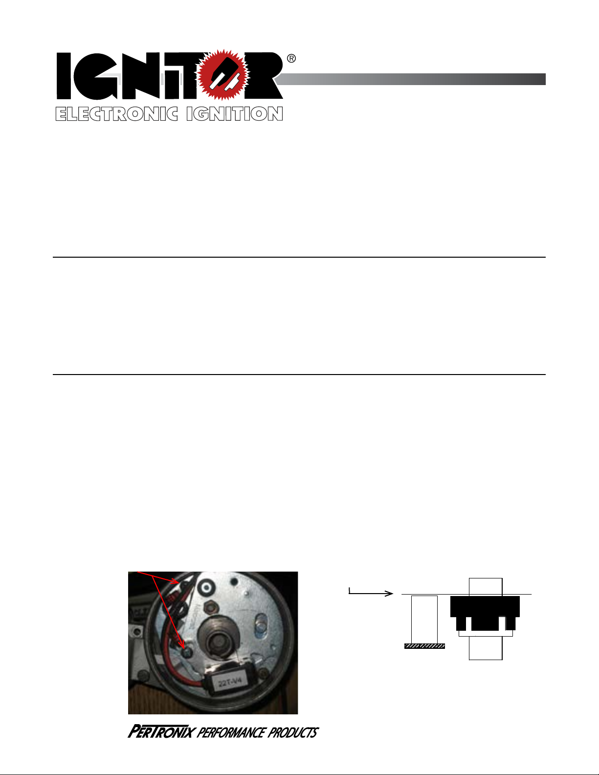
2. Install the Ignitor module using the provided hardware in the same manner as a set points. NOTE: 1281 kits
use the points adjustment screw hole as a pilot for the Ignitor locating pin. Confirm the mounting plate is flat
and fits without any modifications. See Figure 1.
3. If the distributor ground wire was removed during the installation process be sure it is re-attached securely.
NOTE: If the ground wire is missing, one needs to be installed and attached from the point breaker plate to the
distirbutor housing. See Figure 1.
4. Place the magnet sleeve over the distributor shaft, and onto point cam. Press down firmly to insure magnet
sleeve is fully seated. NOTE: Make sure that the Ignitor module and magnet sleeve are level. See Figure 2.
5. Set the air gap between the module and magnet sleeve using the provided plastic feeler gauge (0.030”
thick). This done in the same manner as points.
6. Reinstall the rotor, and the distributor cap. Make sure all spark plug wires are securely attached.
7. See Wiring Instructions.
Ground Wire Location
Figure 1
Magnet Sleeve
Must be level with
Ignitor on top.
Figure 2
909-599-5955 www.pertronix.com
909-599-5955 www.pertronix.com
Page 1 of 4
Page 1 of 4
Page 1 of 4
Page 2
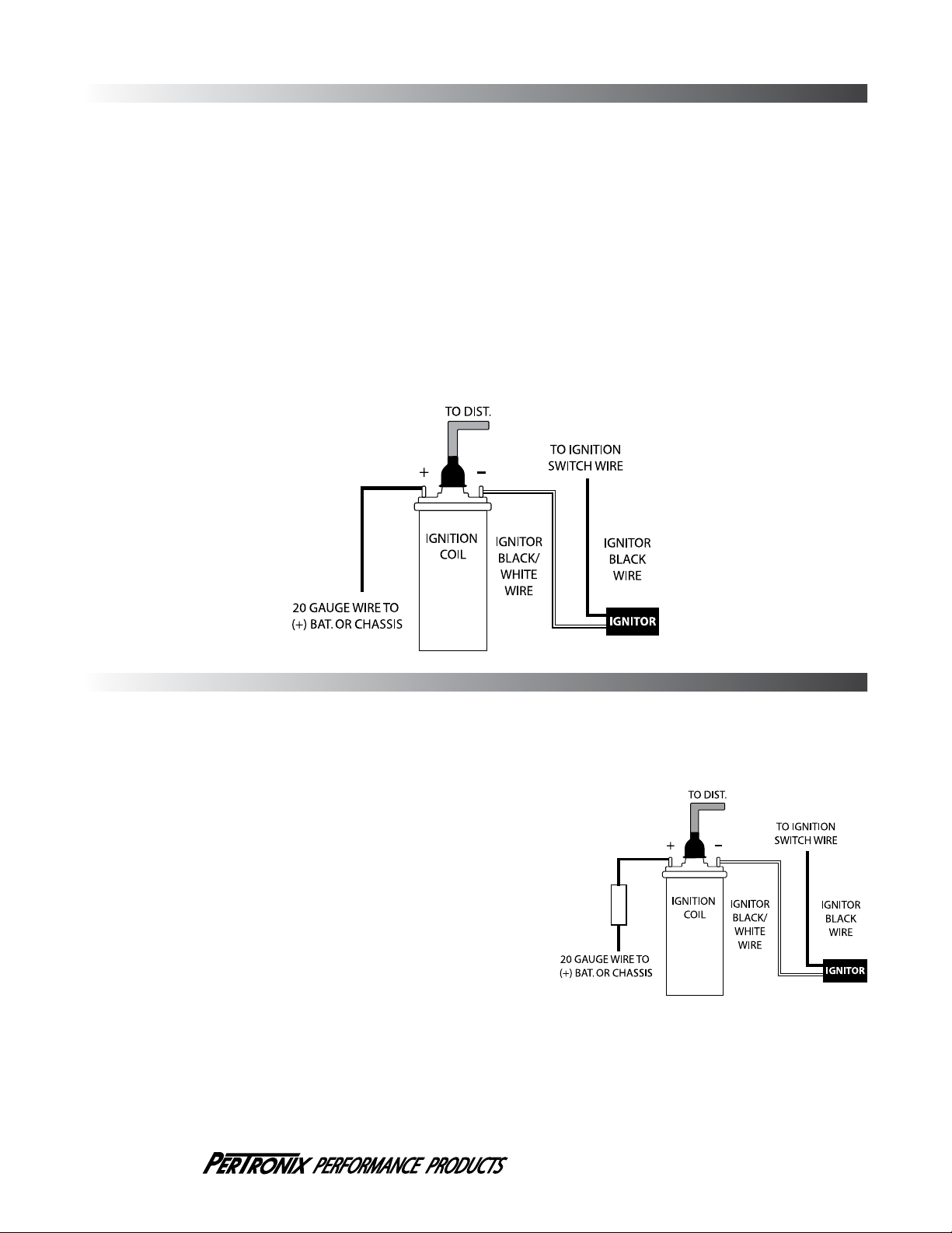
A. Recommended Wiring Installation:
The Ignitor ignition can be used in conjunction with most ignition coils rated at 0.6 ohms of primary resistance on eight cylinder
engines and 1.5 ohms on four and six cylinder engines. For optimum performance purchase and install the recommended
Flamethrower high performance coil.
Many vehicles came equipped with ballast resistor or resistance wire. To achieve optimum performance from the Ignitor ignition
system, we recommend the removal of these components. See last page for coil recommendations.
1. See figure A for wiring diagram.
2. Remove the ignition switch wire from the negative coil terminal.
3. Connect the black Ignitor wire directly to the ignition switch wire.
4. Connect the Ignitor black/white wire to negative (-) side of the ignition coil.
5. Connect an insulated, AWG 20 copper stranded wire from the positive coil terminal to the positive battery or chassis. Note: This wire
is not included in the kit.
6. Make sure all wires are connected correctly, and reconnect battery.
7. The engine can now be started. Let the engine run for a few minutes and then set the timing in the conventional manner.
8. Start the engine and allow it to reach normal operating temperature. Check ignition timing, and adjust to the desired setting.
(FIGURE A)
B. Alternative Wiring Installation:
The Ignitor can also be installed in applications retaining the ballast
resistor. NOTE: Too much resistance in the circuit will cause poor
engine performance or no start condition.
1. See figure B for wiring diagram.
2. Remove the ignition switch wire from the negative coil terminal.
3. Connect the black Ignitor wire directly to the ignition switch wire.
4. Connect the Ignitor black/white wire to negative (-) side of the ignition
coil.
5. Connect an insulated, AWG 20 copper stranded wire
from the positive coil terminal to one side of the
ballast resistor. Connect an insulated, AWG 20 copper
stranded wire from the ballast resistor to the positive
battery terminal or chassis. Note: This wire is not
included in the kit.
6. Make sure all wires are connected correctly, and reconnect battery.
7. The engine can now be started. Let the engine run for a few minutes
and then set the timing in the conventional manner.
8. Start the engine and allow it to reach normal operating temperature.
Check ignition timing, and adjust to the desired setting.
(FIGURE B)
Ballast Resistor
909-599-5955 www.pertronix.com
Page 2 of 4
Page 3

Ignitor COMMON QUESTIONS AND ANSWERS
IGNITOR
BLACK/WHITE
WIRE
IGNITOR
BLACK WIRE
JUMPER
WIRE
VOLTMETER
BLACK LEAD
VOLTMETER
RED LEAD
BATTERY
IGNITOR
MODULE
VOLTMETER
Q. What is the first thing I should check if the engine would not start?
A. Make certain all wires are connected securely to the proper
terminals.
Q. The engine will not start or runs rough. Are there any tests I can
do?
A. Yes, remove the black wire from the ignition switch wire. Connect
jumper wire from the negative (-) side of battery to the Ignitor
black wire. If the engine starts and runs well, you may have high
resistance thru your Ignition switch. This is just a test. Not intended
for permanent installation.
Q. How can I fix a high resistance problem?
A. High resistance can be caused by an external ballast resistor,
resistance wire or in some cases a resisted ignition switch. If the
proper coil is used, remove or bypass all external resistors.
Q. Should I remove the starter bypass wire?
A. No, the starter bypass wire is needed to provide voltage while
starting (cranking).
Q. What type of coil do I need?
A. The ignitor is compatible only with a “points type” coil. Eight
cylinder engines require a minimum of 0.6 Ohms of resistance in the
primary circuit. Four & six cylinder engines require a minimum of 1.5
Ohms of resistance (primary).
Q. How do I check my coil for resistance?
POWER & GROUND TESTS
A. First you need an ohmmeter. Remove all the wires from the coil.
Attach the ohmmeter to both the positive and negative terminals.
The reading should be 0.6 Ohms or greater for eight cylinder
engines and 1.5 Ohms or greater for four & six cylinder engines.
(Your local auto parts store can do this for you if you don’t have an
ohmmeter)
Q. What do I do if my coil does not have enough resistance?
A. You may purchase and install a ballast resistor from your local
auto parts store. You may also choose to purchase a Flamethrower
40,000-volt coil, which provides resistance internally. Note: Many
vehicles come with resistor wire or a ballast resistor. These
applications do not need an additional resistor.
Q. What happens if you leave the ignition switch on when the engine
is not running?
A. This can cause your coil to overheat, which may cause permanent
damage to the coil and the ignitor.
Q. May I modify the length of the wires?
A. Yes, you can cut the wires to any length your application may
require. You may also add length of wire if needed (20-gauge wire).
Please make sure all wire splice are clean and connections are
secure.
Q. How can I get additional help?
A. Call our tech line (909-547-9058) for any further instructions or
questions.
VOLTAGE TESTS (ENGINE DOES NOT START):
1. Connect Voltmeter red lead to positive (+) and black lead to negative (-) terminal of the battery.
2. Crank engine and note voltmeter reading. Make sure that the voltage does not drop under 5.2 volts while the engine is cranking.
Check your battery, cables, connections, and starter draw if the voltage drops under 5.2 volts.
3. Attach the voltmeter red lead to the Ignitor mounting plate and the voltmeter black lead to the negative terminal of the battery.
4. Crank engine and note voltmeter reading. The voltage should note drop under 5.2 volts.
ENGINE STARTS AND STALLS (For testing only):
1. Remove Ignitor black wire from the ignition switch wire.
2. Connect Ignitor black wire to (-) negative terminal of battery. Make sure
you make a good connection at the battery.
3. Crank Engine and see if engine starts. If engine starts, check your
Ignition circuit for bad connections, poor contacts in the Ignition switch,
or some form of resistor in the circuit.
IGNITOR BENCH TEST:
1. Remove the Ignitor from the distributor, this is a bench test.
2. Connect a jumper wire from the Ignitor plate to the battery positive (+)
terminal.
3. Attach the black/white Ignitor wire to the voltmeter black lead.
4. Attach the Ignitor black wire to the negative terminal of the battery.
5. Attach the red lead from the voltmeter to the battery positive terminal.
6. The voltmeter should read battery voltage once all the connections are
made.
7. The magnet sleeve uses one magnet per cylinder. Using a paper clip,
locate and mark one magnet.
8. Rotate the magnet in front of the module; the meter should drop from
battery voltage to 2-3 volts every time the magnet passes the module.
Note: The voltage may drop to 0 volts, this is normal.
9. If the voltage doesn’t drop and you read constant battery voltage, the
Ignitor has failed.
(FIGURE C)
909-599-5955 www.pertronix.com
Page 3 of 4
Page 4

FLAME-THROWER COIL APPLICATIONS
Recommended Flamethrower Coils
Black Chrome Epoxy
Use with:
System
Voltage
Cylinders
Primary
Resistance
Ignitor Only 6V 8 0.6 ohms 45011 45001 45111
Ignitor Only 6V 4 & 6 1.5 ohms 40011 40001 40111
Agricultural & Industrial
Ignitor Only 6V 1,2,3,4, & 6 1.5 ohms 40011 40001 40111
Ignitor Only 6V 8 0.6 ohms 45011 45001 45111
NOTE: REMOVE OR BYPASS EXTERNAL BALLAST RESISTOR OR RESISTANCE
WIRE WHEN INSTALLING THE RECOMMENDED FLAME-THROWER COIL.
LIMITED WARRANTY
Pertronix, Inc. Warrants to the original Purchaser of its solid-state ignition system
(product) that the Ignitor, magnet assembly and wiring (components) shall be free from defects
in material and workmanship for a period of (30) months from the date of purchase.
If within the period of the foregoing warranty Pertronix finds, after inspection, that
the product or any component thereof is defective, Pertronix will, at its option, repair such
products or component or replace them with identical or similar parts PROVIDED that within
such period Purchaser:
1. Promptly Notifies Pertonix, in writing, of such defects.
2. Delivers the defective products product or component to Pertronix (ATTN: Warranty) with
proof of purchase date; and
3. Has installed and used the product in a normal and Proper manner, consistent with
Pertronix printed instructions.
THE FORGOING LIMITED WARRANTY IS EXCLUSIVE AND IN LIEU OF ALL
OTHER WARRANTIES, WHETHER EXPRESSED OR IMPLIED, INCLUDING AND IMPLIED
WARRANTY OR MERCHANTABILITY OR FITNESS FOR A PURPOSE.
THE FURNISHING OF A REPAIR OR REPLACEMENT COMPONENTS SHALL CONSTITUTE
THE SOLE REMEDY OF PURCHASER AND THE SOLE LIABILITY OF PerTronix WHETHER
ON WARRANTY, CONTRACT
BE LIABLE FOR MONEY DAMAGES WHETHER DIRECT OR CONSEQUENTIAL.
OR FOR NEGLIGENCE, AND IN NO EVENT WILL PerTronix
440 East Arrow Highway
San Dimas, CA 91773
909-599-5955
www.pertronix.com
Page 4 of 4
 Loading...