

Page 1
6100 Series Scanner
USERS GUIDE
www.pertechresources.com
220350A -REV 00 October 2007
Page 2

Pertech Resources Inc. October 2007 220350A I
Page 3

Federal Communications Commission (FCC) Radio
Frequency Interference Statement
Warning
Changes or modications to this unit not expressly approved by the party responsible for compliance could void the user’s authority to operate the equipment.
Note
This equipment has been tested and found to comply with the limits for a Class A digital device, pursuant to Part 15 of the FCC rules. These limits are designed to
provide reasonable protection against harmful interference when the equipment is operated in a commercial environment. This equipment generates, uses, and
can radiate radio frequency energy and , if not installed and used in accordance with the instruction manual, may cause harmful interference to radio communica-
tions. Operation of this equipment in a residential area is likely to cause harmful interference in which case the user will be required to correct the interference at
his own expense.
Information to the User
This equipment must be installed and used in strict accordance with the manufacturer’s instructions. However, there is no guarantee that interference of radio
communications will not occur in a particular commercial installation. If this equipment does cause interference, which can be determined by turning the equip-
ment off and on , the user is encouraged to contact Pertech immediately.
Pertech is not responsible for any radio or television interference caused by unauthorized modication of this equipment, or the substitution of attachment or con-
nection cables and equipment other than those specied by Pertech. The correction of interferences caused by such unauthorized modication, substitution or
attachment will be the responsibility of the user.
Important Information to the User
In order to ensure compliance with the Product Safety, FCC and additional agency markings requirements, you must use the power supply, power cord, and inter-
face cable which were shipped with this product.
Power Supply
(LPS) output for use in North America, input rated 100 - 240 Vac, .4 A, 50/60 Hz, Output rated 24Vdc, .625 A Maximum and 15W Maximum. Use of this product with
a power supply other than the approved Pertech power supply supplied will require you to test this power supply and the Pertech scanner for FCC and additional
agency mark certications. For more information check with your Pertech representative for current agency requirements.
Interface Cable
A shielded (360 degree) USB certied interface cable must be used with this product. The shield must be connected to the frame or earth ground reference at each
end of the cable.
Use of a cable other than the described here will require that you test this cable with the Pertech scanner and your system for FCC and USB mark certication.
Power cord
For North America a NRTL Recognized detachable power cord must be used. For applications where the power supply module may be located on the oor, a
power cord with Type SJT marking must be used.
For applications outside of North America, Power cords which meet the country of installation’s certication and application requirements must be used.
Use of a power cord other than described here may result in a violation of safety certications which are in force in the country of use.
Disclaimer
Information in this document is subject to change without notice. Consult your Pertech sales representative for information that is applicable and current. Pertech
reserves the right to improve products as new technology, components, software and rmware become available.
No part of this document may be reproduced or transmitted in any form or by any means, electronic or mechanical, for any purpose with out the express written
permission of Pertech.
Industry Canada
This Class A digital apparatus complies with Industry Canada Standard ICES-003.
Cet appareil numérique de la classe A est conforme à la norme NMB-003 d’Industrie Canada.
Copyright
Copyright © 2007 by Pertech Resources Inc..
Riverton, Wyoming USA
All rights reserved. Printed in USA. Condential,
Unpublished. Property of Pertech® Inc...
Trademarks
Pertech® is a trademark of Pertech Resources, Inc. Other trademarks
and registered trademarks are the property of their respective holders.
Web site
http://www.pertechresources.com/
Pertech Resources Inc. October 2007 220350A II
Page 4

Contents
Where to Get Additional information ...........................................................1
Preface .......................................................................................................1
Models & Options .......................................................................................1
Unpacking the Scanner ..............................................................................2
Choosing a Location...................................................................................2
About the 6100 Scanner ............................................................................ 3
Features Identication ...............................................................................3
Cables and Connections ............................................................................4
Connecting the Cables ...............................................................................4
USB 2.0 Interface .......................................................................................4
Printer View ................................................................................................4
Power Supply .............................................................................................5
Hardware and Software Requirements ......................................................5
Installing the Driver..................................................................................... 5
Power Supply Connector............................................................................ 5
Operating the Scanner ...............................................................................6
Typical Form Handling ...............................................................................6
Typical Form Scanning Process................................................................. 6
LED Indicators ............................................................................................7
ID Card Scanning Process .........................................................................7
Stamp Installation & Replacement .............................................................8
Preventive Maintenance .............................................................................9
Clearing Jams.............................................................................................9
Feed Issues ................................................................................................9
6100 Scanner Specications ....................................................................10
Dimensions............................................................................................... 10
Service & Support..................................................................................... 11
Warranty Information ................................................................................ 11
Pertech Resources Inc. October 2007 220350A III
Page 5
Preface
This manual has been written to help you Install and Operate your Pertech® 6100 Series Scanner. Feel
free to contact us if you need further assistance after reading this manual. Please see the Troubleshooting
Scanner Problems section of this manual and determine the complete part number of your scanner prior to
calling. Pertech provides technical support Monday through Friday from 8:00 AM to 5:00 PM MST at 307856-4821.
Every effort has been made to insure the information in this manual is complete and accurate. Feel free to
contact us with any comments concerning this manual. Pertech assumes no responsibility for errors.
Where to Get Additional information
The following publications contain more information about the 6100 series scanner. Contact your Pertech
sales representative to obtain additional copies of this Manual or any of the publications listed below.
Title Part Number
6100 Scanner: Setup Guide 220349
6100 Scanner: Users Guide 220350
6100 Scanner: Service Guide 220351
6100 Scanner: Pertech API Programming Manual 220346
6100 Scanner: Command Manual 220347
6100 Parts Information Manual
Ordering Supplies
The following section lists the paper and supplies available for order. In addition to paper and ribbons,
Parts, service and repair may be obtained by calling 1-800-800-6614.
Description Part Number
Sun Stamp 108762-001
Imaged Stamp 108762-002
6100 Scanner Certied USB Cable 6’ 106356-011
6100 Scanner Certied USB Cable 10’’ 106356-014
6100 Scanner Contact Image Sensor Wipe 108784
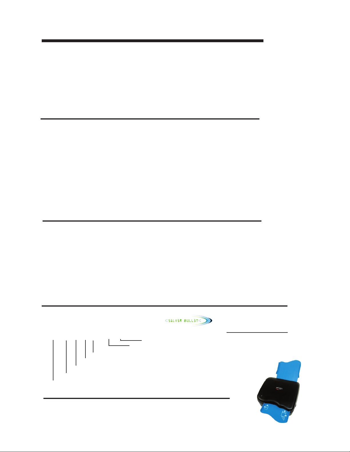
Models & Options
Available Models:
613211-001
}
}
DPI Capability - 2=200, 4=400
Contact Image Sensor - Color - 2=2 Color, 3= B/W
Model Series 61=6100 Family
}
}
}
MICR - 0=No, 1= Yes
}
Stamp - 1= Yes, 2=No
}
Unique Feature Identier
Software Compatibility Identier
5=Ranger Silver Bullet, 0= None
Unique Item Examples
Orientation Vertical or Horizontal
Stand
Adjustable Deck Guide
Deck Options
Case Color
Firmware
Logos
Cables
www.pertechresources.com
Pertech Resources Inc. October 2007 220350A 1
Page 6
Unpacking the Scanner
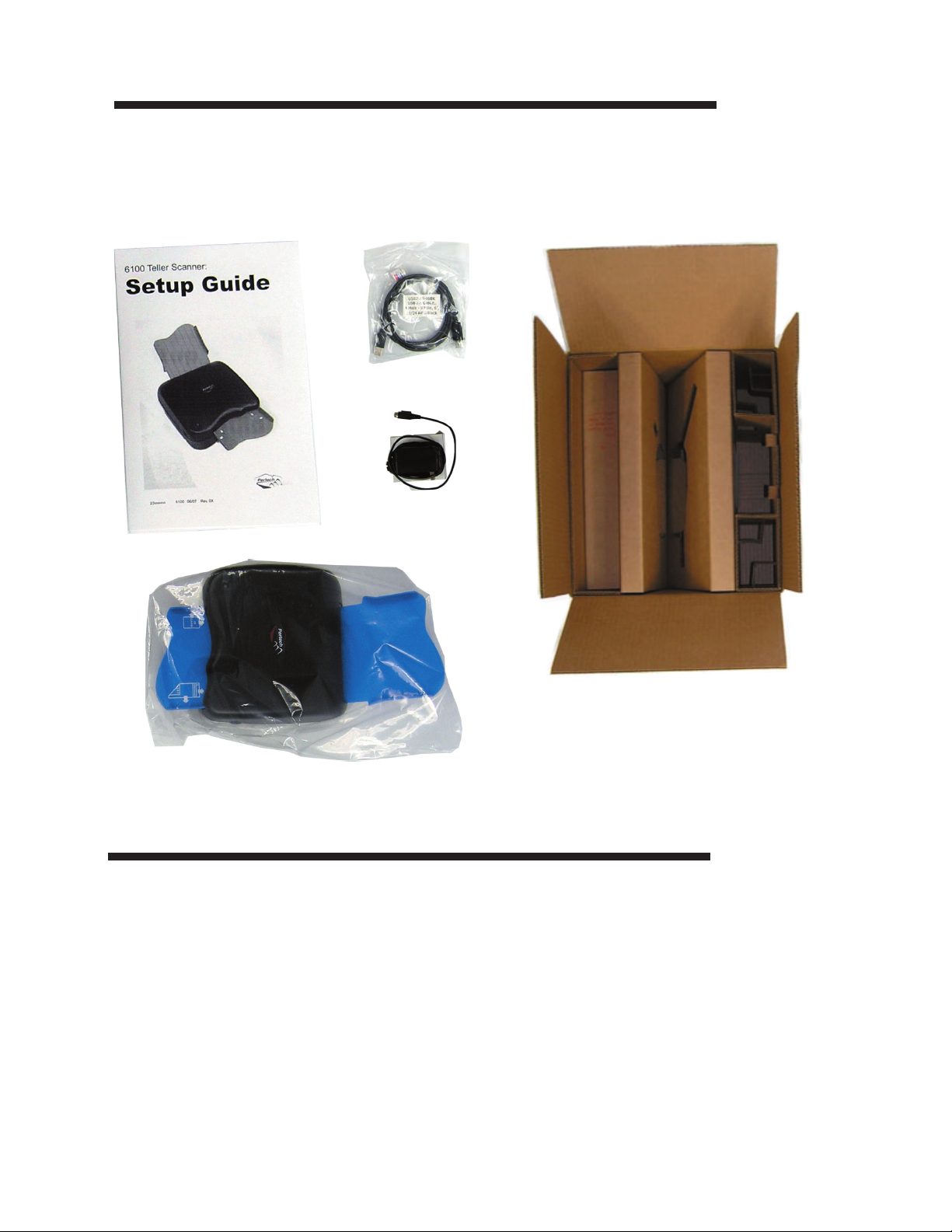
Save all packing materials in case you need to repack the scanner.
To report a scanner that was damaged during shipping, see “Contact Information” on the last page of this
Guide.
To repack the scanner, consult the below illustration and use the original packing materials.
Choosing a Location
Place the scanner on a level surface on or near the host computer. Leave space to open the cover, and to
insert a form.
The maximum distance from the scanner to the host and the power supply is: 6 feet (USB interface). The
scanner should be placed in a location that minimizes Electro-Magnetic Interference (EMI), a minimum of 1
foot away from monitors.
Pertech Resources Inc. October 2007 220350A 2
Page 7
About the 6100 Scanner
The 6100 scanner is a manual single sheet feed imaging solution that has duplex imaging, (both front and
back of form). The scanner is capable of rear exit single pass stacking of at least 10 checks, and images
standard 256 bit gray scale @ 200DPI imaging. Image compression is CCITT
(grayscale). The 6100 Series Scanner also has an optional MICR reader and form defacing stamp. USB
2.0 interface comes as the standard interface.
G4 (black/white) or JPEG
The MICR reader is in-line with the image scanner with on-board
acters. Comes Standard with 32MB of DRAM memory upgradeable to a maximum of 64MB and super fast
document processing speed of 10 inches per second.
rmware decoding of E13B MICR char-
Features Identication
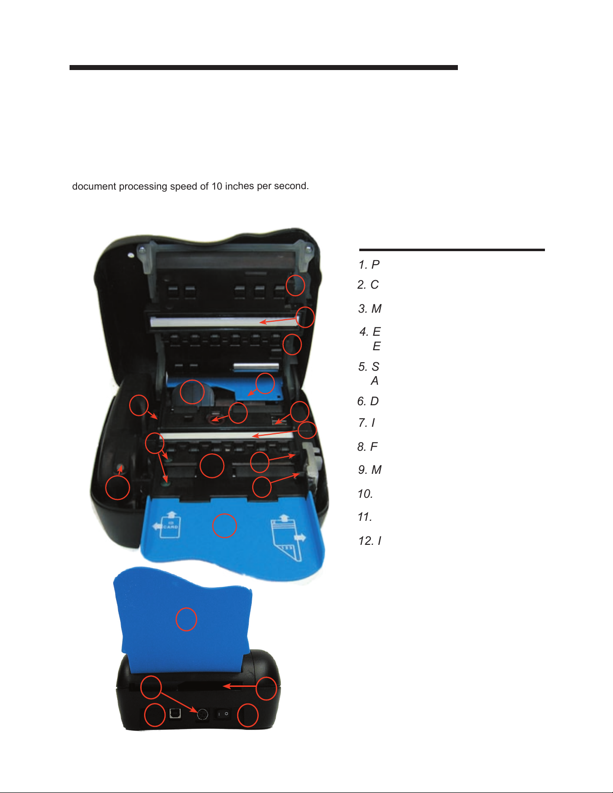
1. Pressure Rollers
1
2
1
4
12
5
7
6
3
2
2. Contact Image Sensor
3. MICR Read Head
4. Entrance to Rear
Exit Tray
5. Stamp Release
Actuator
6. Defacing Stamp
7. ID Card Sensors
8. Form-in Sensor
13
10
11
9
8
9. Mechanism Feed Sensor
10. LED Indicator
11. Entrance Tray
12. ID Card Diverter
13. Mid-Field Sensor
1. Rear Deck
1
2. ID Card Exit Path
3. USB Interface
4
3
Pertech Resources Inc. October 2007 220350A 3
2
5
4. Power Connector
5. Power Switch
Page 8
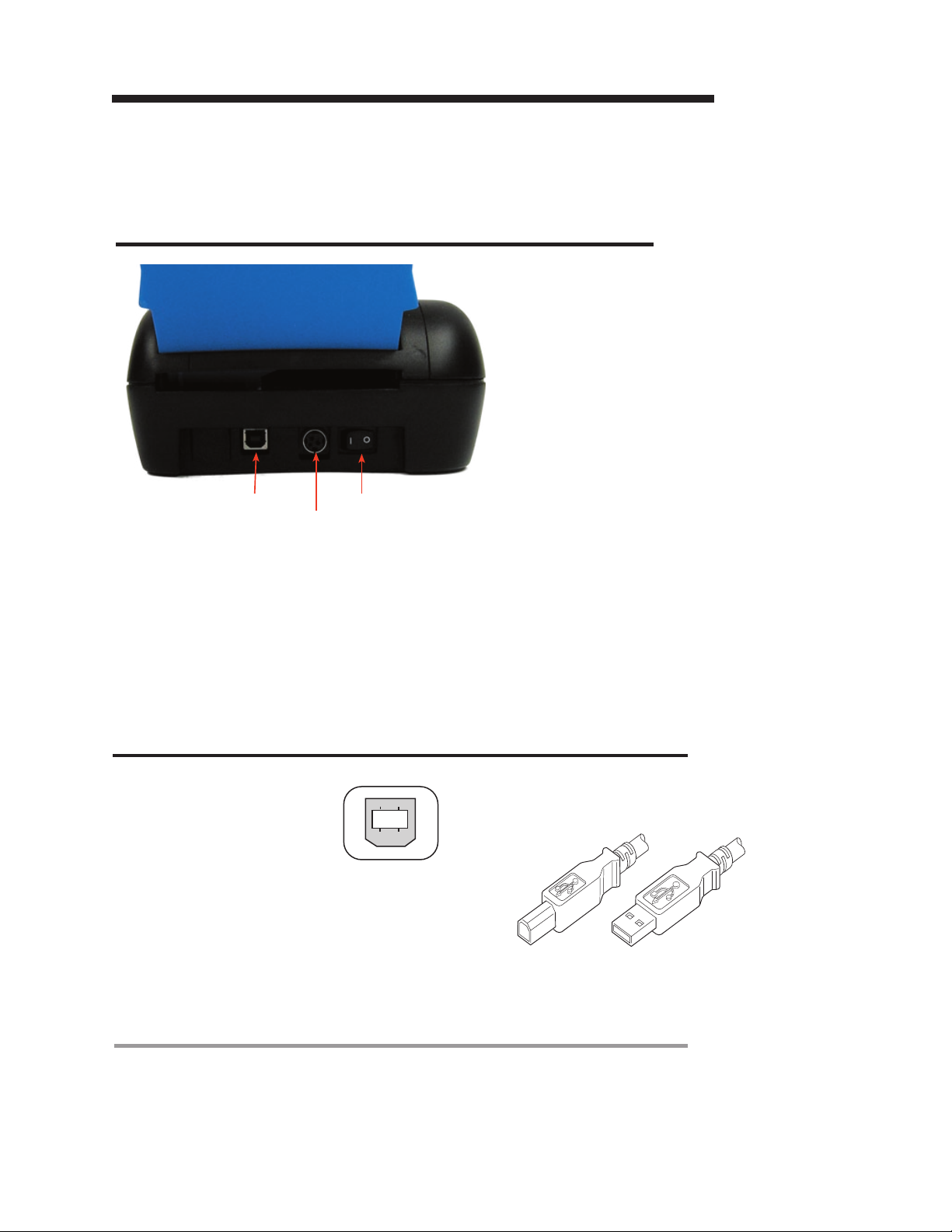
Cables and Connections
Connecting the Cables
Caution: Be sure the power switch is turned off before
connecting cables.
USB Interface
Power Connection
1. Make sure the unit is on a level surface.
2. Make sure the Scanner is powered off.
3. Connect the Power Supply to the Scanner.
3. Connect the Power Supply to the Power Source.
4. Connect The USB cable to the back or the scanner.
5. Load drivers on the PC (See Page 5 of this manual).
6. Connect the USB Cable to the PC and turn the scanner on.
Power Switch
USB 2.0 Interface
Standard Pinout
Pin 1 EOT/VCC
Pin 2 DPin 3 D+
Pin 4 GND
Pin 5 GND
Pin 6 GND
The USB cable may be attached or detached when the
system is on. When Using the USB interface the Windows® Operating System will automatically install the
USB port driver. Pertech has available scanner drivers
at www.pertechresources.com.
Printer View
Warning: When Hot Swapping USB cable
make sure that cable is installed into the
correct connectors or damage to the scanner
could result.
USB Cable Part
Number 106356011
Pertech Resources Inc. October 2007 220350A 4
Page 9
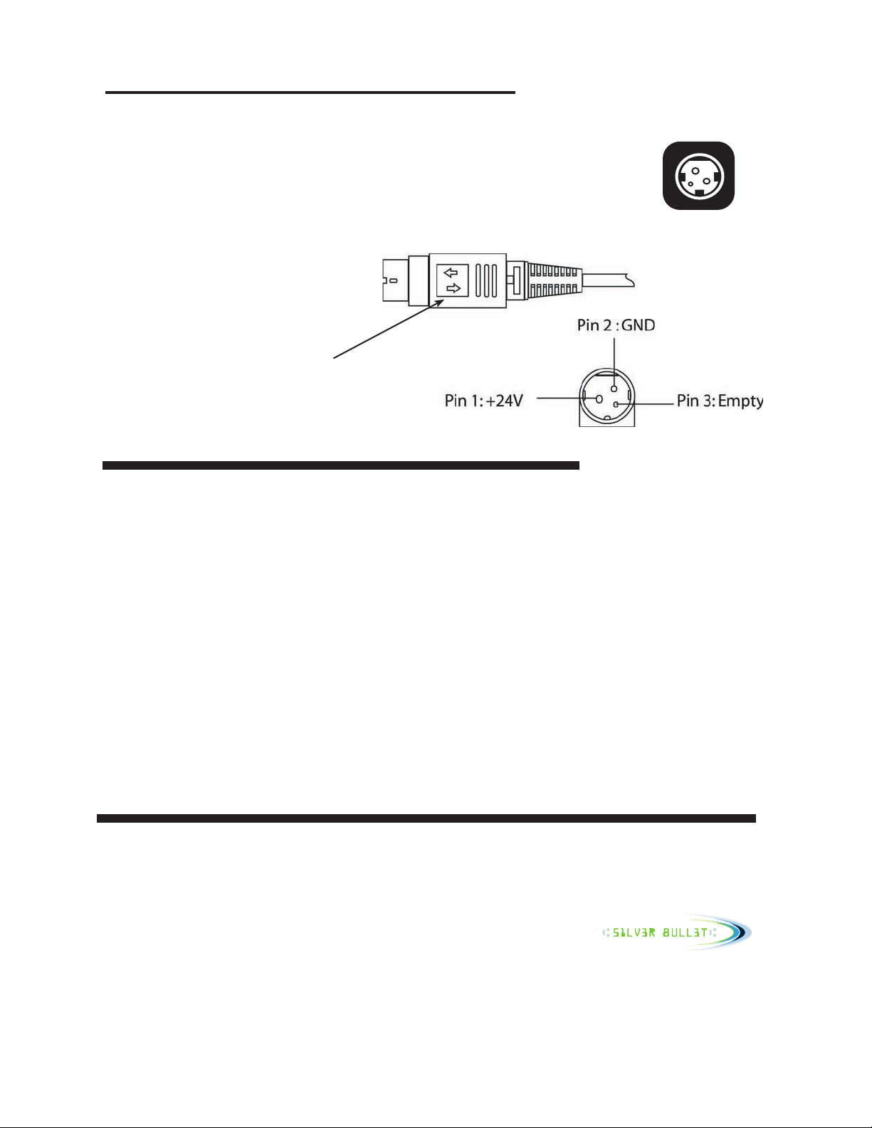
Power Supply
To avoid damage to the scanner connect the Power Supply last.
1. Make sure the scanner power switch is off.
2. Plug the Power Supply Cable into the scanner. The power supply cable connector has a locking mechanism to ensure that the cable stays fastened to the
scanner. When removing the cable release the locking mechanism by pulling the
mechanism away from the scanner.
3. Plug the Power Supply Cable into a grounded outlet.
4. Reference “Connecting the Cables” on the previous page to complete the process.
Connector Cable
Locking Mechanism
Printer
Connectiion
Installing the Driver
Power Supply Connector
Windows XP, 2000, Vista Drivers
1.Download the 6100 USB driver from the Pertech Website. Unzip the le to a directory of your choosing . Make a
note of this location. (Silver Bullet users can skip this step and install the Silver Bullet software.)
2.Next, plug in the 6100 into the host computer’s USB 2.0 bus and power up the unit.
When the 6100 Check Scanner is plugged into a USB port for the rst time, Windows XP
will automatically start the “New Hardware Wizard”. Follow the instructions of the hardware
wizard, Browse to the directory where the unzipped 6100 driver les are located. (Silver Bullet users will automatically nd the driver les.
3.Windows will give a message that the driver is not signed, click “Continue Anyway” to install the driver.
Note that this also installs a WIA class device for the 6100, but the check scanner cannot be used in this manner.
Running the scanner requires writing an application that accesses it
through the supplied PertechAPI.
Note, driver installation for Silver Bullet models is done as part of the Silver Bullet Software installation. See Silver
Bullet documentation for additional instructions regarding Silver Bullet software.
Hardware and Software Requirements
USB 2.0
Windows XP, 2000, or Vista Operating System. Pentium 4, 256MB RAM or higher recomended.
Windows drivers / SDK /Application Program Interface are available off the Pertech Web site. The 6100 Scanner
can be purchased with Silver Bullet Technology plug and play capability.
www.pertechresources.com
Pertech can supply an API for developers who wish to interface the scanner directly into their application software.
Contact your Pertech Representative for the necessary les and documentation.
Pertech Resources Inc. October 2007 220350A 5
Page 10
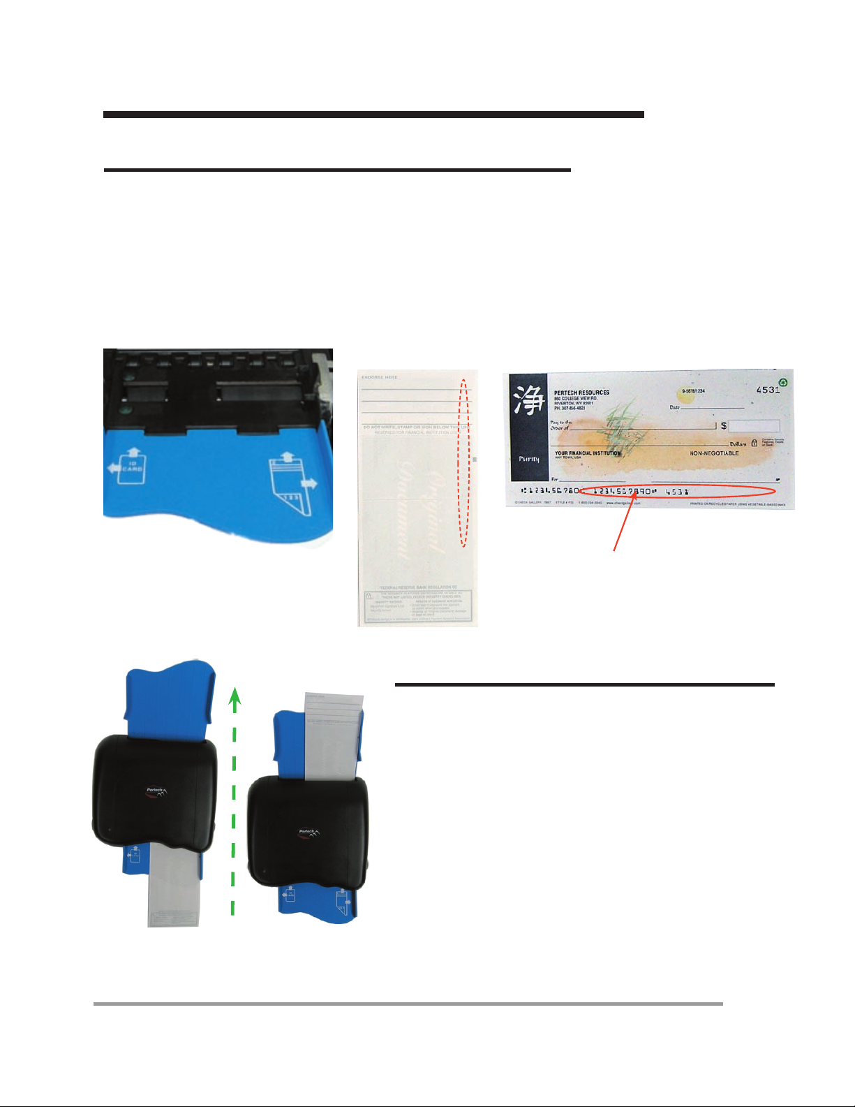
Operating the Scanner
Typical Form Handling
The 6100 teller scanner handles forms between 2 and 3.67
inches wide and 3.2 to 8.75 inches in length. The scanner will handle thicknesses between #16 to #32
(3.0 to 7.5 mills; .032" for ID Cards), with rear exit single pass stacking of a of 10 checks. The unit has a
in-line MICR reader with on board software for decoding E13B MICR characters
To load a form into the scanner insert the form justied to the right, face down with the
MICR line to the right side of the scanner.
Check face down with
MICR Line to Right side
MICR Line
Typical Form Scanning Process
The application software calls for the user to insert a form
into the scanner. The Green Power On LED begins blinking
to indicate that the scanner is waiting for a form.
There are two sensors (#8,#9) identied in the Features Identication on page 3. The rst sensor tells the scanner that a
form is present, activates feed the motor and draws the form
into the scanner.
The second sensor, if activated, passes the form through to
the imaging heads and MICR reader and ejects the form out
the back of the scanner onto the Exit Tray.
If the second sensor does not activate, as in the case of a
inserted form being skewed, the user will need to realign the
form with the right side of the scanner Entrance Tray before
feeding the form.
Pertech Resources Inc. October 2007 220350A 6
Page 11
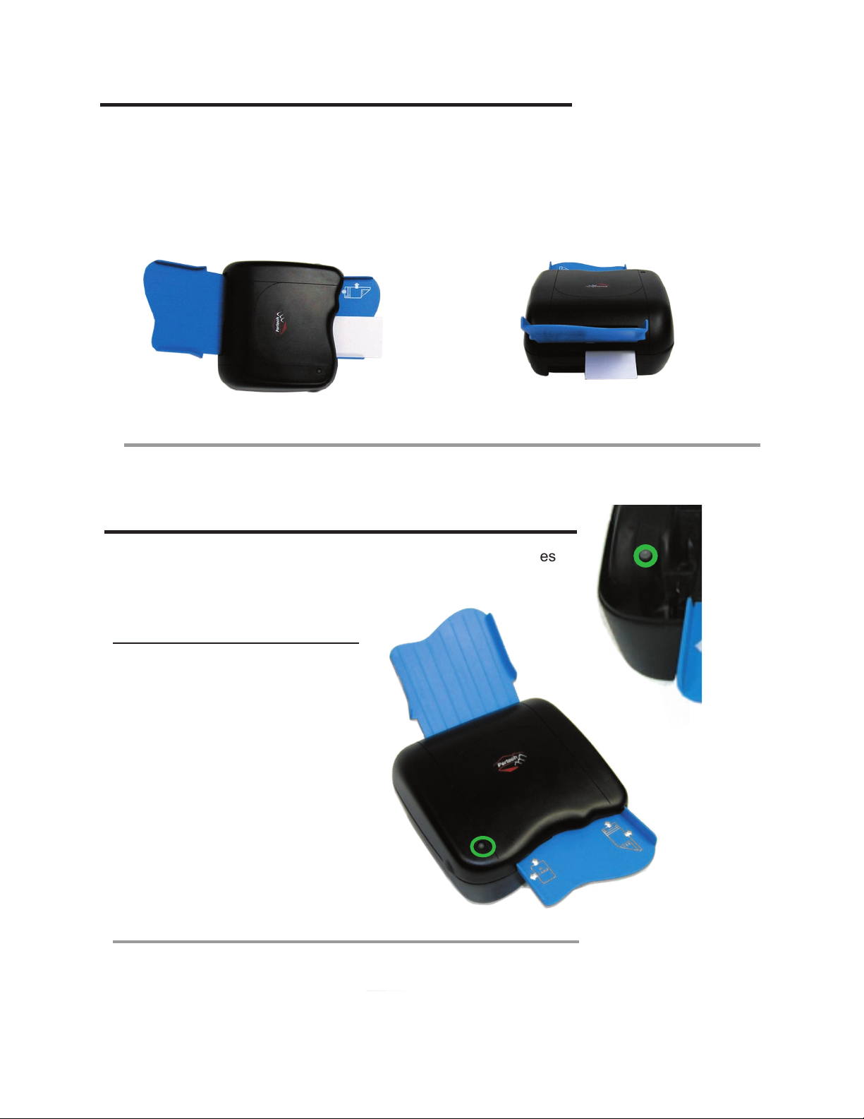
ID Card Scanning Process
The application software calls for the user to insert a ID card into the scanner, the Green Power On LED
begins blinking to indicates that the scanner is waiting for a ID card.
There are two sensors (#7) identied in the Features Identication on page 3. The rst sensor tells the
scanner that a ID card is present, activates feed the motor and draws the ID card into the scanner.
The second sensor if activated passes the ID card through to the imaging heads and ejects it out the ID card
Exit Path (#2 on the bottom image of the Features Identication) in the back of the scanner.
Back of Scanner
LED Indicators
Equipped with one three color led indicator that typically identies
Power on, Ready for Form, and Error.
(See Note Below).
Status Right LED
Power On Green
Insert form Blink Green
Error Red
Note:
LED functions can also
be dened via control
commands. Application
developers see the 6100
programing manual for
details.
Contact your Pertech
Representative for the
necessary les and
documentation.
Pertech Resources Inc. October 2007 220350A 7
Page 12
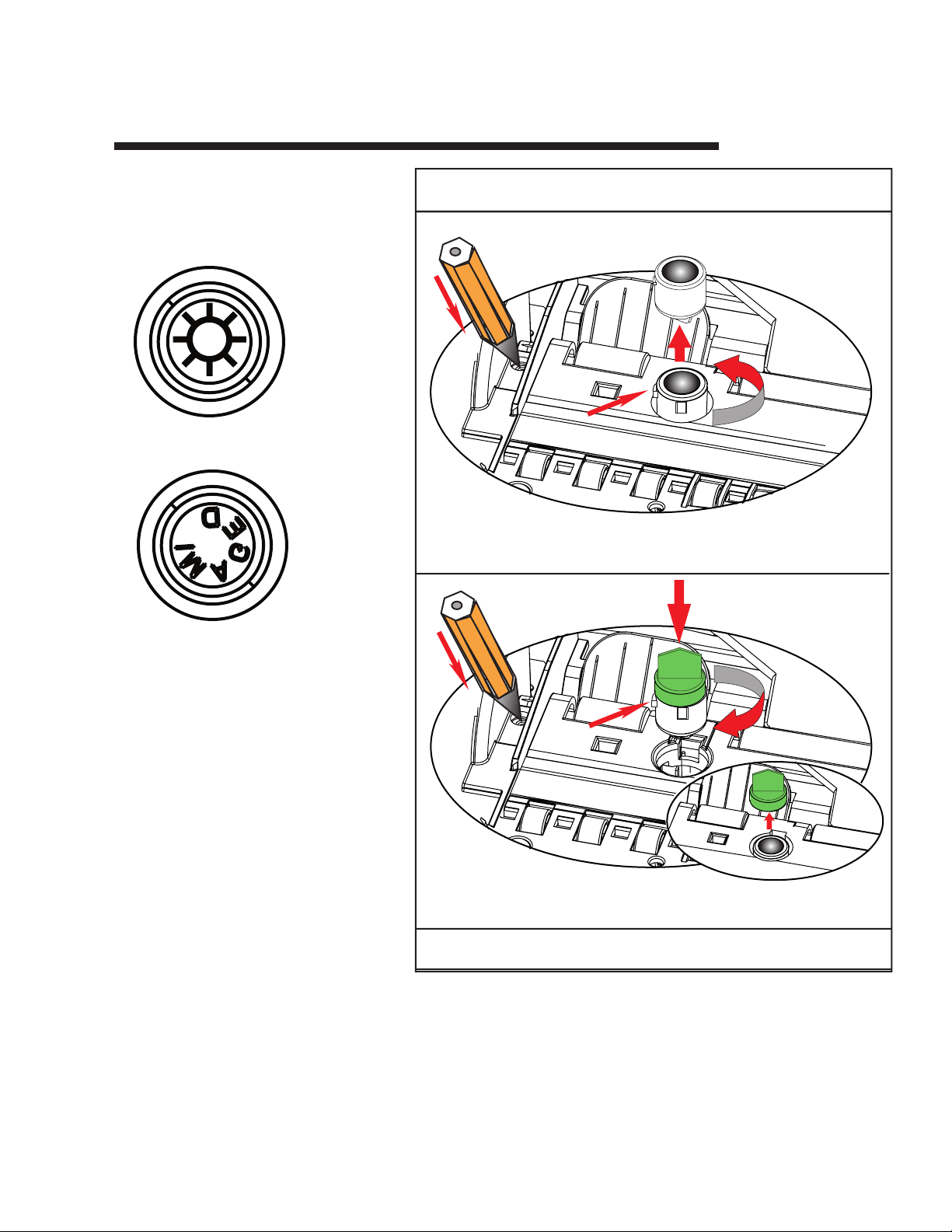
Stamp Installation & Replacement
Stamp Replacement
To Reorder Call 800-800-6614
Removal
Installation
Step 1
Step 1
Step 2
Step 2
Stamp Tab Must Be Rotated Counter
Clockwise 90° For Stamp Removal
Stamp Tab Must Be Rotated Clockwise
90° For Stamp Installatiion
TAB
Step 3
TAB
The defacing stamp can be purchased
as either a Sun or a IMAGED stamp.
The stamp is designed for easy replacement and has a capability of up to 10,000
stamps.
Sun Stamp
PN 108762-001
Imaged Stamp
PN 108762-002
Step 1 Installation & Removal
Insert a pencil or pen end into the stamp
release and press lightly.
Step 2 Removal
Turn Stamp Counter Clockwise 90º and
lift stamp out of stamp locking mechanism.
Step 2 Installation
Orient the new stamp so that the tab
is 90º from the back of the stamp slot.
Insert the stamp and rotate clockwise to
lock into the mechanism.
Pertech Resources Inc. October 2007 220350A 8
Page 13
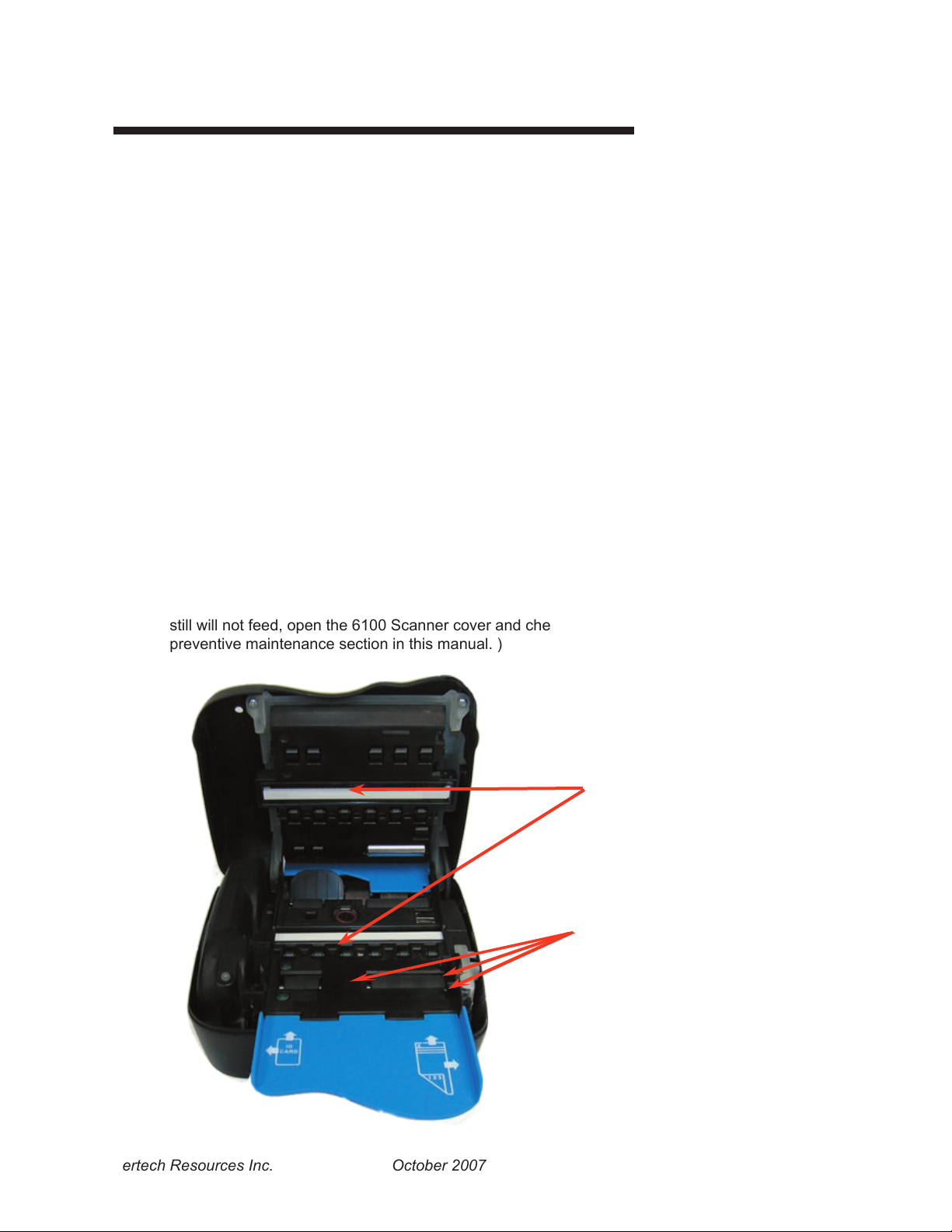
Preventive Maintenance
There is no customer maintenance required for the 6100 scanners. However, scanners gather paper dust
and other debris through normal use, continued accumulation can eventually lead to imaging issues. A
general preventive maintenance program can help reduce unnecessary failures and downtime. Pertech
recommends that you occasionally clean lint and paper dust out of the scanner using low pressure canned
air. It is recommended that this be done on a regular basis, such as once a month. Clean the cabinet as
needed to remove nger marks and dust. Use any household cleaner designed for plastics, but test it rst
on a small, inconspicuous area. Additionally, contact sensors should be cleaned with an approved Pertech
Cleaning Wipe.
Caution: Do not spray or try to clean the Contact Imaging Sensors (CIS) or the inside of the scanner with
any kind of cleaner other than what is recomended. This may damage the CIS or the electronics.
Clearing Jams
If a jam occurs the paper path can be accessed simply by opening the cover. Access to the full
paper path allows the user to remove the jam without the hassle of trying to wiggle, pry, or eject
the form. When clearing a jam clear the paper path of any documents, paper dust etc.... make
sure rollers are free of debris. Close cover to resume operation
.
Feed Issues
If the document is not being grabbed by the rst roller check to see if the form alignment is correctly aligned with the sensor on the right side of the entrance tray. If alignment is OK and form
still will not feed, open the 6100 Scanner cover and check for paper or debris and remove.( See
preventive maintenance section in this manual. )
Use Pertech PN# 108784
Approved Cleaning Wipe
Contact Image Sensor
Use Canned Air to Clean
Form-in Sensor
Mechanism Feed Sensor
Mid-Field Sensor
Pertech Resources Inc. October 2007 220350A 9
Page 14
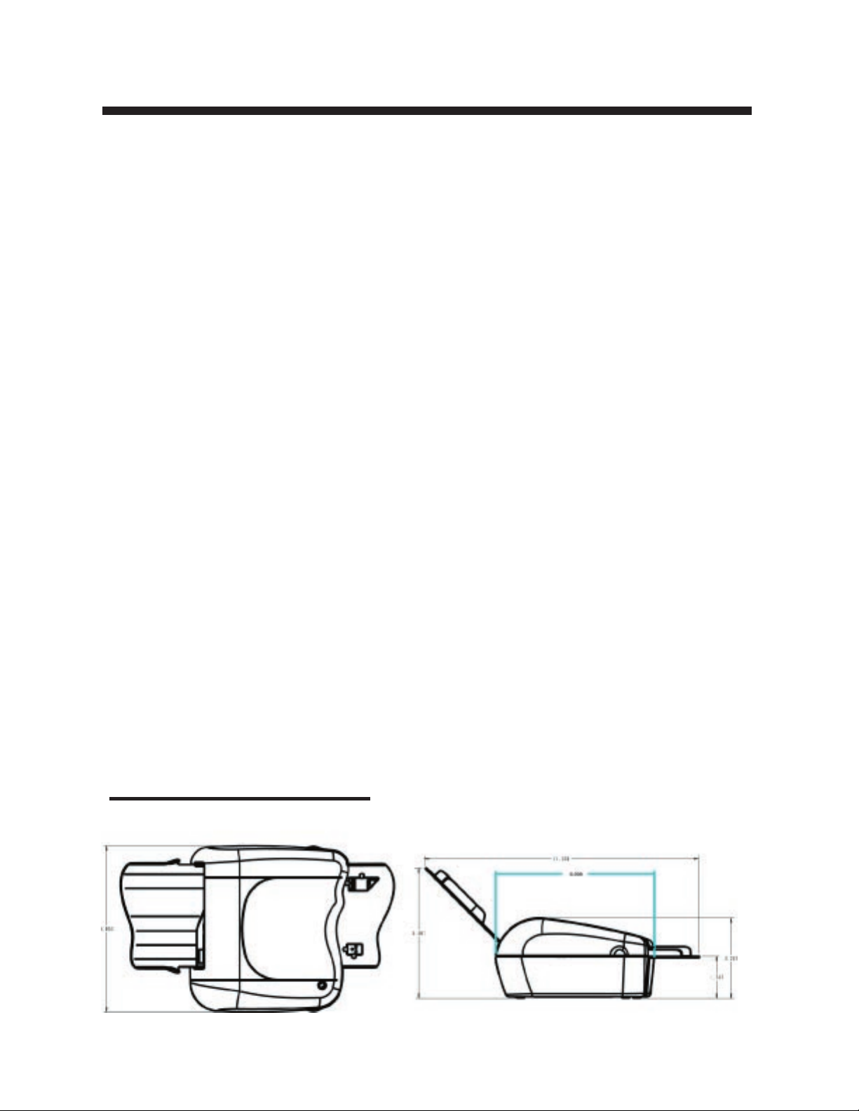
6100 Scanner Specications
Dimensions
Height 5.38” / ( 136.65mm)
Width 6.85” / (173.99 mm)
Length 11.3” / (287mm)
Orientation Horizontal
Weight
Imager 2.2 Lbs. / (1.0 Kg.)
Ext. Power Supply 1.12 Lbs. Max. / (.051 kg)
Power Supply 24V Wall Mt, 3 Pin Mini Din Locking Connector
Form
Width 2” (50.8mm) MIN, 3.67” (93mm) MAX
Length 3.2” (80mm) MIN, 8.75” (222mm) MAX
Weight / Thickness #16 up to 32# or 3.0 to 7.5 mils, .032”(81mm) for ID Cards
Image Quality 8 Bit Grey Scale @ 200DPI
24 Bit Color Option 200DPI
200-400 DPI Option Monochrome
Image Compression CCITT G4 (Black / White) or JPEG (Grayscale).
Micr In Line with Image Scanner
On- Board E13B Decoding Firmware
Sensors Form Insert, Jam & Skew
Indicators Three Color Status LED -- Green, Yellow, Red
Interface High Speed Capable , USB 2.0
Memory 32 MB DRAM upgrade able to 64MB
Speed
Processing Time Single Pass Max 1.5 Seconds
Document Speed 10 Inches Per Second
OS Compatibility XP/2000 / Vista (Nov 2007)
API Interface
Pertech Proprietary API Or Interface with Silver Bullet’s Ranger API
Diagnostics Command Based Self Test Feature
Maintenance General Periodic Cleaning takes less than 2 min and
Can be performed by the operator.
Reliability
Life Seven Years under normal usage
Warranty 2 Years
Environmental
Noise 58 dB
Operating 10˚ to 40˚ C, Humidity 10-85% Non-Condensing
Storage -10˚ to 40˚ C, 10-85% Non-Condensing
Agency Listings TUV CUE Conforms to EU CE, WEEE and RoHS directives
Emissions FCC 15B Class A
Drivers Windows XP, 2000,Vista Nov 07
Dimensions
Pertech Resources Inc. October 2007 220350A 10
Page 15

Service & Support
Pertech provides Technical Support for this product by calling 307-856-4821 between the hours of
8AM to 5PM Monday through Friday MST, or by submitting a Support Inquiry at the Pertech web site.
www.pertechresources.com under the service/support section.
The Model Number, Revision, Date, and Serial Number can be located on the Label attached on the bottom
of the scanner. Please have this information available when you contact Pertech.
Warranty Information
Current product warranty infromation can be found on the Pertech Website.
www.pertechresources.com
Warranty
Pertech Resources warrants all of its transaction printers and scanners against defects in material and
workmanship for a period of 24 months from date of shipment by Pertech Resources or the rated maximum number of transactions for the specic product – whichever comes rst. Kiosk printers, mechanisms
and distributed products carry warranties specic to their application or manufacturers’ warranty. Contact
[email protected] for details on the specic product warranty.
Pertech Resources does not consider damage caused by replacement ribbons, stamps or replacement
parts supplied by parties other than Pertech Resources to be a defect in material or workmanship. This
is a limited warranty, limited exclusively to its terms, including the exclusive remedies set forth below. In
addition, this warranty is void if the product has been altered, misused, taken apart or otherwise abused.
All other warranties, expressed or implied are excluded, including but not limited to the implied warranties
of merchantability and tness for particular purpose. Any warranty claims must be supported by proof of
purchase, represented by reference to the customers’ purchase order.
Buyer’s Remedies
Pertech Resources’ obligations and liabilities under the foregoing warranty are limited to repair or replacement of the product without charge, provided it is shipped prepaid to Pertech Resources, 860 College
View Drive, Riverton, WY 82501-2298. A charge is made for repairs after the expiration of the warranty
period. In addition, if a product is returned and replacement ribbons, stamps or other replacement parts not
supplied by Pertech Resources have caused the product damage, a reasonable charge for repair will be
assessed. Product returned under warranty discovered to be a “no fault found” will be charged the standard repair cost plus return freight. In no event shall Pertech Resources be liable for claims based upon
breach of expressed or implied warranty or negligence or any other damages whether direct, immediate,
foreseeable, consequential or special or for any expenses incurred by reason of the use or misuse, sale or
fabrications of products which do not conform to the terms and conditions of this contract.
Pertech Resources Inc. October 2007 220350A 11
Page 16

Pertech
�
For Additional Information
About Pertech® Products
Contact us at the address
below or visit our Web site.
www.pertechresources.com
Copyright© 2007 Pertech Resources, Inc.. All Rights Reserved.
Patents pending. All trademarks or registered trademarks are
the property of their respective owners. Printed in U.S.A. Prod-
uct specications are subject to change.
Pertech Resources Inc.
860 College View Drive
Riverton, WY 82501
800-800-6614
Pertech Resources Inc. October 2007 220350A 12
 Loading...