

Page 1
INSTALLATION AND OPERATION INSTRUCTIONS
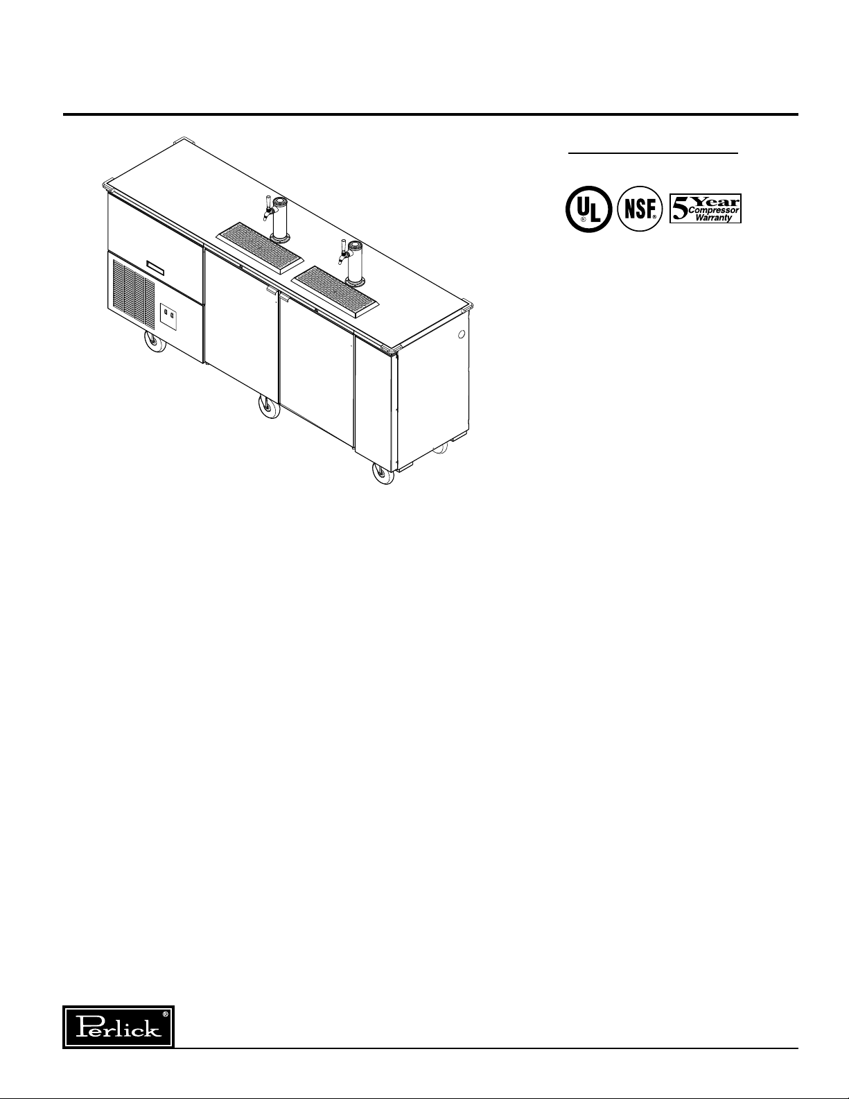
ARCTICOLD DRAFT DISPENSER
MODEL NOS.
DC90ACLT
IMPORTANT INFORMATION
To register your product, visit our web site at
(www.perlick.com). Click on “Commercial”, then
“Service”. You will see the link to “Warranty
Registration Form”. You must complete and submit
this form or the installation date will revert back to
the ship Date. The unit comes with a one year
parts warranty.
This manual has been prepared to assist you in the
installation of your ArctiCold Draft Dispenser and to
acquaint you with its operation and maintenance.
We dedicate considerable time to ensure that our
products provide the highest level of customer
satisfaction. If service is required, your dealer can
provide you with a list of qualified service agents.
For your own protection, never return merchandise
for credit without our approval.
We thank you for selecting a Perlick product and
assure you of our continuing interest in your
satisfaction.
WARNING: When lifting, the full weight of the
cabinet must be supported. Lift from the cabinet
base and not from the top. Improper lifting can
result in severe damage to the cabinet.
Table of Contents
Preparing the Cabinet for Use
Specifications ........................................................2
Initial Setup............................................................3
Electrical ................................................................3
Tapping
Connecting the Keg Coupler.................................4
Tapping the Keg/Priming the System ...................4
Connecting the Regulator .....................................5
Adjusting Gas Flow ...............................................5
CO2 Leak Test .......................................................5
Replacing a CO2 Gas Cylinder..............................5
Handling CO2 Gas .................................................5
Cleaning
Cleaning the Beer Lines ........................................6
Cleaning the Cabinet .............................................6
General Information
How to Pour a Perfect Glass of Beer ...................7
Wiring Diagrams ....................................................8
Glycol Loop Diagrams ...........................................9
Preventative Maintenance ...................................10
8300 West Good Hope Road • Milwaukee, WI 53223 • Phone 414-353-7060 • Fax 414-353-7069
Toll Free 800-558-5592 • E-Mail: Perlick@Perlick.com • www.Perlick.com
Form No. Z2323
Rev. 06.26.10
Page 2
Installation and Operating Instructions
24”
[
610
]
24 1/16”
[
610
]
44”
[
1118
]
24 3/4”
[
629
]
92 3/4”
[
2355
]
19 7/8”
[
504
]
DOOR OPENING
R23 1/16”
[
586
]
18 3/4”
[
476
]
BACK OF LINER TO
INSIDE OF DOOR PAN
42 15/16”
[
1091
]
33”
[
837
]
91”
[
2311
]
14”
[
356
]
12”
[
305
]
26 1/2”
[
673
]
7 1/2”
[
191
]
55 13/16”
[
1417
]
43 1/16”
[
1094
]
35 9/16”
[
904
]
12 11/16”
[
322
]
10 1/2”
[
267
]
3 3/16”
[81]
8 5/8”
[
220
]
27 1/2”
[
698
]
DOOR
OPENING
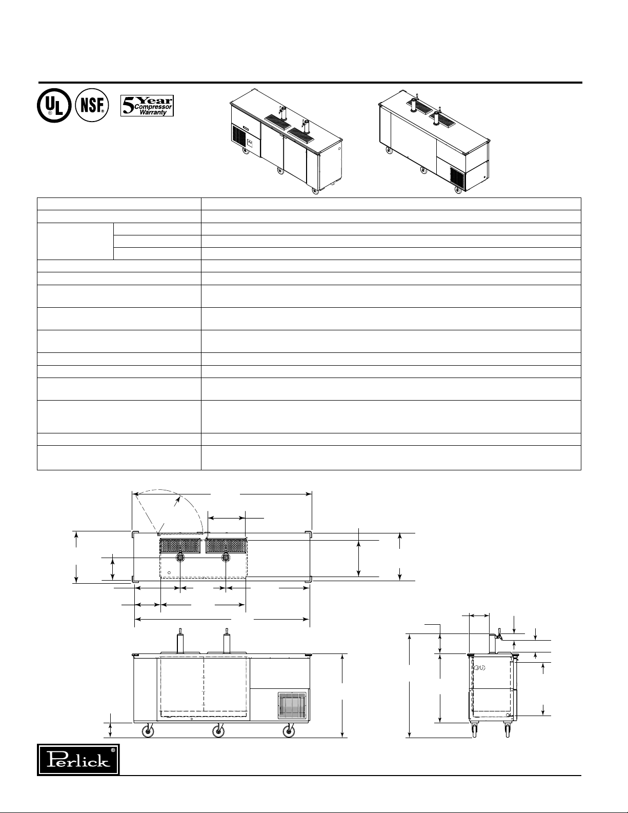
Specifications, ArctiCold Draft Dispenser
*
MODEL NOS. DC90ACLT
KEG CAPACITY
CABINET
DIMENSIONS
INCLUDING
BUMPERS
Length Inches. (mm) 923/4” (2311)
Depth Inches. (mm) 261/2” (673)
Height Inches. (mm) 5513/16” (1354)
CONDENSING UNIT H.P.
SHIP WT
INTERIOR Door sill
EXTERIOR
lbs. (kg) 805 (366)
: High strength polyethylene. Door pan and ceiling: High impact polystyrene.
Walls and Floor pan
: Stainless steel.
Stainless steel top and doors. Choice of stainless steel or galvanized back and sides.
Bottom galvanized.
REFRIGERATION
R-134a expansion valve system. Epoxy coated aluminum fin and copper tube evaporator, coil.
Digital temperature control. Self-defrosting.
1
GLYCOL MIXTURE
VENTILATION
PLUMBING
/3 propylene glycol to 2/3 distilled water.
All sides of unit must be unobstructed to ensure adequate ventilation.
Evaporator condensate and beer waste is pre-plumbed to a waste tank located in
the CO2 compartment.
ELECTRICAL Unit is furnished with 3-prong (NEMA) 5-15 plug, 9 foot long power cord that requires a
dedicated 15 amp circuit of 115 volt, 60Hz, 1 phase AC electricity. Disconnect power cord
before servicing.
INSULATION
OPTIONS &
ACCESSORIES
* This product is intended for the storage of non-potentially hazardous canned and bottled products only.
Foamed-in-place environmentally friendly polyurethane; 2” walls, 11/2” top and floor.
Options: • Two single faucet dispensing heads or one dual faucet head.
Accessories: • Keg couplers • Regulators • Faucet locks
2 Keg
1
/3 HP
Form No. Z2323
Rev. 06.26.10
Perlick is committed to continuous improvement. Therefore, we reserve the right to change specifications without prior notice.
2
NOTE: Shown with optional
two single faucet draft arms.
Page 3
Preparing the Cabinet for Use –
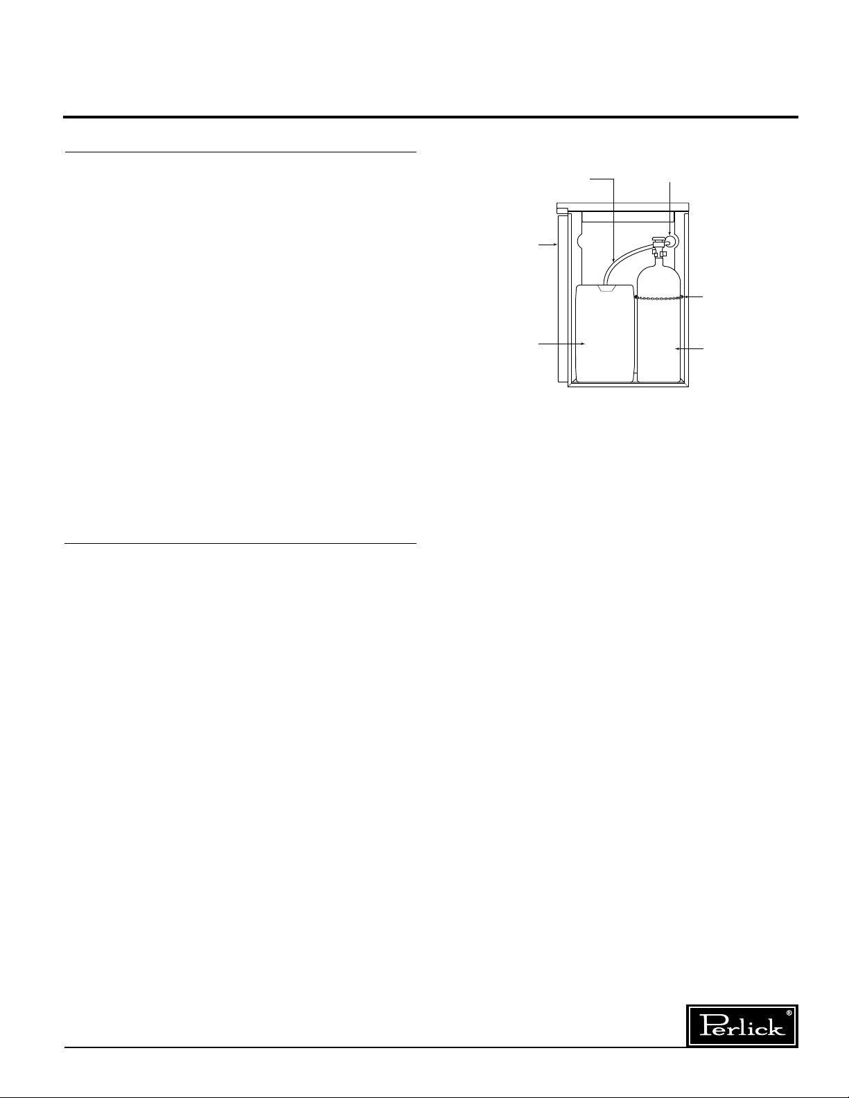
DUMP TANK
CO2 CYLINDER
ACCESS DOOR
CHAIN FOR
SECURING
CO2 CYLINDER
CABINET
ACCESS
HOLE
DRAIN TUBE
FROM
DRAINER
REMOVABLE
DUMP TANK
CO2 TANK
(Must Be Secured
When Moving
Cabinet)
ArctiCold Draft Dispenser
Uncrating and Inspection
Remove all crating material before operating.
Carefully inspect cabinet for hidden damage. If
damage is discovered, file your claim immediately.
Perlick is not responsible for damage in transit.
Ensure that the unit is on a level surface and that
the brakes on the casters are engaged. It is important that the unit is unobstructed on all sides to
provide adequate ventilation for the refrigeration
decks. Blocking the ventilation louvers may
damage the compressor and void the warranty.
Remove the bottom front grille to access the
machine compartment. Connect the power cord
to a separate dedicated circuit as described in
the electrical section of this manual. Turn on the
rocker switch labeled “circulating pump” and
check for glycol leaks. Next, turn on the rocker
switch labeled “condensing unit”. The flash chill
heat exchangers and evaporator coil circuit will pull
down to operating temperature in less than 1 hour
in most conditions.
Electrical
The power cord is a 15 amp cord that requires
115 VAC, 60Hz, and 1 phase electricity. Refer to
the wiring diagram included in this manual for a
detailed schematic.
WARNING: Always disconnect power cord
before servicing.
Perlick is committed to continuous improvement. Therefore, we reserve the right to change specifications without prior notice.
3
Form No. Z2323
Rev. 06.26.10
Page 4
Installation and Tapping
OUT
DOWN
1/4
TURN
OUT
DOWN
1/4
TURN
OUT
DOWN
1/4
TURN
ArctiCold Draft Dispenser
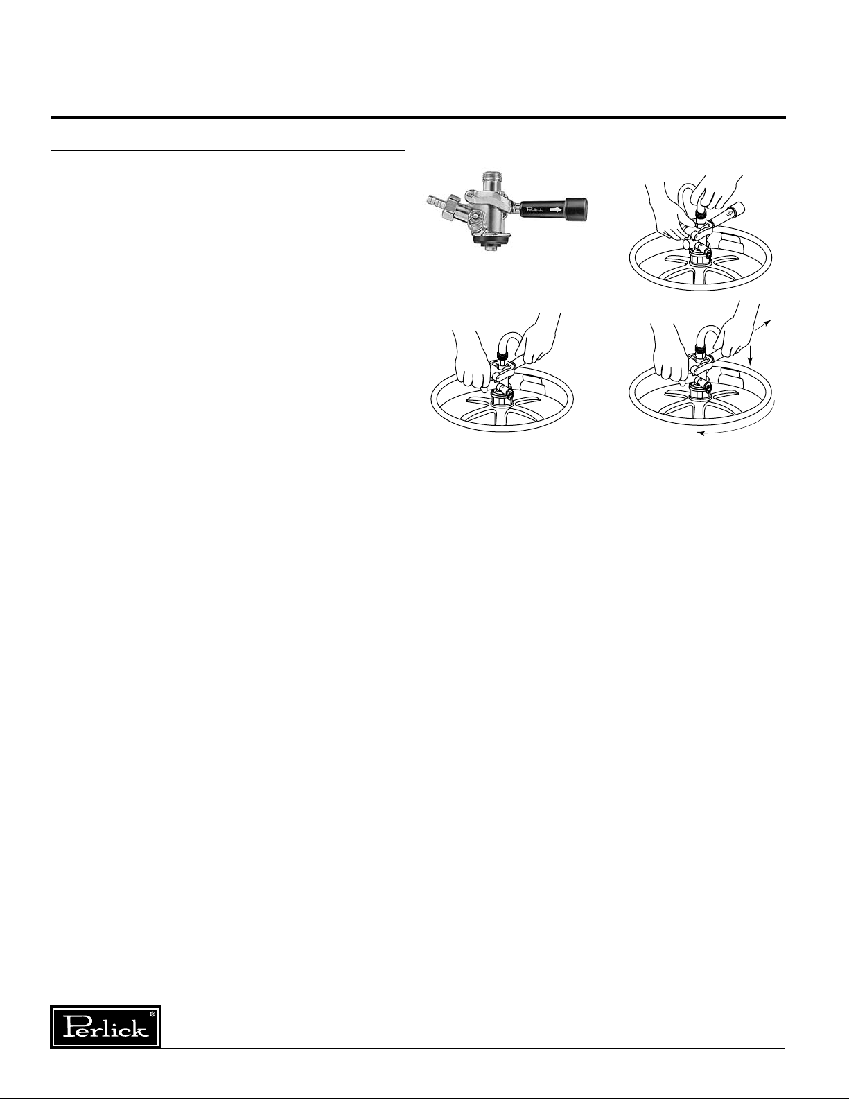
Tapping a Single Valve Keg (Sankey)
■
Be sure beer faucet is in closed position.
■
Align keg lugs with lug openings on bottom
of coupler.
■
Turn clockwise 1⁄4 turn. Pull handle out and
down. Keg is now tapped.
■
Open shut-off valve on CO2 distributor located
inside
IMPORTANT: Be sure to close this valve
when untapping keg.
CAUTION: Do not use keg coupler as a
handle to lift keg.
Priming the Beer System
■
Plug in top refrigeration deck, (15-amp plug),
and allow condensing unit to cycle at least
once, (circulation pump will run continuously),
before tapping the keg
■
Couple beer keg to system. Beer temperature
in keg should not exceed 42°F.
■
Apply 14-17 PSIG carbon dioxide gas.
■
Open faucet and pour for approximately 15
seconds.
■
Close faucet and wait for at least 15 minutes to
allow beer system to “pack”.
■
You are now ready to tap beer.
of the cabinet.
.
Step 1
Single Valve Keg Coupler
Step 3
Step 2
Form No. Z2323
Rev. 06.26.10
Perlick is committed to continuous improvement. Therefore, we reserve the right to change specifications without prior notice.
4
Page 5

Installation and Tapping
CO2
PRESSURE
GAUGE
CO2
GAS
DRUM
REGULATOR
FITTING
REGULATOR
ADJUSTING
SCREW
FITTING FOR
RED AIR HOSE
SHUT-OFF VALVE
(BLACK LEVER IN
CLOSED POSITION)
HAND
VALVE
PERLICK
PSI
10
50
0
60
20
40
30
ArctiCold Draft Dispenser
Connecting the Regulator to the
CO2 Cylinder
■
(Note: Do not remove the carbonic washer).
■
Tighten with wrench until vertically straight.
Be sure that shut-off valve (
regulator is in the OFF (horizontal) position.
■
and push onto regulator tailpiece. Tighten
clamp with a screwdriver.
Adjusting the CO2 Gas Flow
■
wise until it turns freely.
■
cylinder to the fully open position.
■
desired pressure is reached (approximately
12-15 lbs.). The desired pressure may vary
based on location/elevation. Tighten stop nut
on adjusting screw.
■
CO2 Leak Test
Dilute a small amount of liquid dish washing soap
and rub the soapy mixture around each connection. If bubbles appear, tighten connection.
Remove blue plug from regulator fitting.
Screw regulator onto gas cylinder valve.
black lever) on
Place a screw clamp over end of red air line
Turn regulator adjusting screw counterclock-
Turn hand valve counterclockwise on CO2
Turn regulator adjusting screw clockwise until
Open shut-off valve on bottom of regulator.
Replacing CO2 Gas Cylinder
■
Turn CO2 hand valve clockwise until seated and
close shut-off valve on regulator.
■
Unscrew regulator from cylinder fitting.
■
Replace carbonic washer (Part No. 157F2P),
if needed and reattach regulator to filled
cylinder.
■
Turn CO2 hand valve counterclockwise until
fully open. Turn regulator shut-off valve to
open position.
■
Adjust CO2 gas flow as required, turning
clock wise for higher pressure.
Proper CO2 Handling
always...
■
Connect a regulator (reducing valve) to
CO
■
storage or in use.
■
vents at 122° F. maximum.
■
■
before filling. If more than five years old, the
cylinder must be retested to DOT specifications.
■
or dirt before attaching regulator.
■
upright.
■
personnel to handle high pressure gas.
never...
■
regulator (reducing valve).
■
■
■
■
not save gas by doing so!
■
handle high pressure gas.
Failure to heed this warning could result in
personal injury or death.
2 cylinder.
Secure cylinder in upright position whether in
Keep cylinder away from heat. Rupture disc
Ventilate room after high pressure gas leakage.
Check the last DOT test date on cylinder neck
Be sure CO2 cylinder outlet fitting is free of dust
Store CO2 cylinder and regulator assembly
Allow only properly trained and experienced
Connect cylinder directly to a keg without a
Drop or throw regulator or CO2 cylinder.
Transport CO2 cylinder in a closed vehicle.
Apply oil to a regulator.
Shut off CO2 cylinder when not in use. You will
Allow untrained, inexperienced personnel to
Perlick is committed to continuous improvement. Therefore, we reserve the right to change specifications without prior notice.
5
Form No. Z2323
Rev. 06.26.10
Page 6

Cleaning the Beer System
ArctiCold Draft Dispenser
The entire beer system, to include the faucet, flexible
beer line and tapping devices must be cleaned at
regular intervals. We recommend flushing the entire
system with fresh water immediately after a keg has
been emptied. Every two weeks or before each use
the system should be cleaned chemically.
It is recommended that you purchase Perlick’s
Pump Type Cleaning Kit. It is equipped with an
adapter that attaches directly to the faucet shank,
jar with pump, cleaning solution, faucet brush and
spanner wrench.
Cleaning the draft beer system will help to
eliminate the buildup of the following materials:
■
Bacteria:
Beer is an excellent food for bacteria (none of
which is harmful). Proper conditions may begin
the growth of bacteria in draft beer and on the
beer faucet. By regular cleaning, we prevent
this bacterial buildup and maintain the quality
of the draft beer. Greenish or yellowish colored
material on the faucet may indicate bacterial
growth.
■
Yeast:
All domestic draft beers contain a small amount
of yeast which remains in the beer from the
fermentation process. When the temperature of
draft beer exceeds 50° a process of secondary
fermentation may take place. The beer faucet
may exhibit a white colored substance (yeast
build up) if not cleaned on a regular basis.
■
Beer Stone:
All beer contains calcium which is present from
the grains used in the brewing process. It is an
important natural material in draft systems in
that as it oxidizes it coats the internal parts
of the beer lines and equipment. The beer
stone will continue to build if the system is
not cleaned properly or regularly and can
cause drawing problems if it begins to flake
off. Beer stone is present if one can see a
brownish color on the faucet or inner wall of
the beer line, or tobacco- like flakes in the beer.
Cleaning the Cabinet
Use a mild detergent and water to clean the inside
and outside of the cabinet. Dry thoroughly. Never
use a scouring pad or abrasive cleanser.
NOTE:
can be used to clean the outside of painted
cabinets.
An industrial strength, commercial cleaner
Form No. Z2323
Rev. 06.26.10
Perlick is committed to continuous improvement. Therefore, we reserve the right to change specifications without prior notice.
6
Page 7

Pouring a Perfect Glass of Beer
ArctiCold Draft Dispenser
➠
STEP 1
Start with a clean glass.
Place the glass at a 45°
angle, one inch below
faucet. Do not let the
glass touch the faucet.
Open the faucet all the
way.
STEP 2
After the glass has
reached half full,
gradually bring the
glass to the upright
➠
STEP 3
Let the remaining beer
run straight down the
middle of the glass.
This ensures proper
release of CO2 by
producing a 3⁄4” to 1”
foam head.
➠
position
STEP 4
➠
Close the faucet quickly
and completely.
Perlick is committed to continuous improvement. Therefore, we reserve the right to change specifications without prior notice.
7
Form No. Z2323
Rev. 06.26.10
Page 8

Wiring Diagrams
ArctiCold Draft Dispenser
Form No. Z2323
Rev. 06.26.10
Perlick is committed to continuous improvement. Therefore, we reserve the right to change specifications without prior notice.
8
Page 9

Glycol Loop Diagrams
FLASH CHILL/FIN COIL CIRCUIT
GLYCOL
TANK
TUBE
IN
TUBE
TUBE
IN
TUBE
EVAPORATOR
FIN COIL
PUMP
REFRIG. DECK
CABINET
HEAT
EXCHANGER
ArctiCold Draft Dispenser
Perlick is committed to continuous improvement. Therefore, we reserve the right to change specifications without prior notice.
9
Form No. Z2323
Rev. 06.26.10
Page 10

Preventative Maintenance
92 3/4”
24 3/4”
43 1/16”
53 3/8”
26 1/2”
91”
ArcticCold Draft Dispenser
Cleaning the Condenser
The condensing coil should be inspected before
each operation and cleaned if necessary. The
condensing coil can be accessed by removing the
louvered cover located on the customer side of the
cabinet. The coil can be adequately cleaned with
a vacuum, stiff bristled brush, or forced air. Please
use care to ensure that the fins of the condenser
are not bent or damaged.
Glycol Level
The glycol system should be checked before each
operation to ensure an adequate level. The glycol
reservoir can be accessed by removing the louvered cover on the refrigeration deck. The reservoir
is located at the right rear of the deck, (see figure
A). Remove the sponge insulation and unscrew the
cover. While using a mirror, ensure the glycol level
is at the visible seam inside the reservoir located
approximately 2" below the threads. Contact the
Perlick Corporation for proper glycol solution if
needed.
Pump Motors
Sleeve-bearing pump motors should be oiled at
least once per year, (see figure A).
Casters
The casters should be greased at least once every
6 months. This may be required more often if the
unit is used in dusty environments. There is a
grease fitting located on each caster.
Form No. Z2323
Rev. 06.26.10
Perlick is committed to continuous improvement. Therefore, we reserve the right to change specifications without prior notice.
10
Page 11

Perlick is committed to continuous improvement. Therefore, we reserve the right to change specifications without prior notice.
11
Form No. Z2323
Rev. 06.26.10
Page 12

8300 West Good Hope Road • Milwaukee, WI 53223 • Phone 414-353-7060 • Fax 414-353-7069
Toll Free 800-558-5592 • E-Mail: Perlick@Perlick.com • www.Perlick.com
Perlick is committed to continuous improvement. Therefore, we reserve the right to change specifications without prior notice.
Form No. Z2323
12
Rev. 06.26.10
 Loading...