

Page 1
INSTALLATION AND OPERATION INSTRUCTIONS
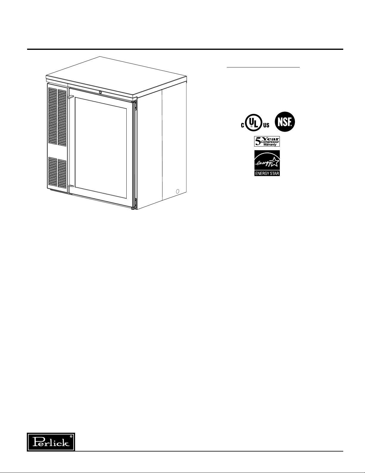
SINGLE DOOR COOLER SERIES
MODEL NOS.
CS32SB
CS32SG
CS32SS
CS32ST
IMPORTANT INFORMATION
To register your product, visit our web site at
(www.perlick.com). Click on “Commercial”, then
“Service”. You will see the link to “Warranty
Registration Form”. You must complete and submit
this form or the installation date will revert back to
the ship Date.
This manual has been prepared to assist you in the
installation of your Single Door Cooler and to acquaint
you with its operation and maintenance.
We dedicate considerable time to ensure that our
products provide the highest level of customer
satisfaction. If service is required, your dealer can
provide you with a list of qualified service agents. For
your own protection, never return merchandise for
credit without our approval.
We thank you for selecting a Perlick product and
assure you of our continuing interest in your
satisfaction.
Table of Contents
PREPARING THE CABINET FOR USE
Specifications ........................................................2
List of Included Parts .............................................
Tools Required ......................................................3
Plumbing ................................................................3
Electrical ................................................................
Uncrating ...............................................................3
Installing Casters ...................................................
Placing the Cabinet ...............................................3
Leveling the Cabinet ..............................................3
Installing Base Plates ............................................
TEMPERATURE
Refrigeration and Temperature Control .................4
Adjusting the Temperature ....................................
CLEANING
Cleaning the Cabinet .............................................4
Cleaning the Condenser ........................................4
Condenser .............................................................4
GENERAL INFORMATION
REPLACEMENT PARTS .......................................
Wiring Diagram ......................................................6
Door Switchiing Instructions ..................................
3
3
3
3
4
5
7
WARNING: When lifting, the full weight of the
cabinet must be supported. Lift from the cabinet
base and not from the top. Improper lifting can
result in severe damage to the cabinet.
8300 West Good Hope Road • Milwaukee, WI 53223 • Phone 414-353-7060 • Fax 414-353-7069
Toll Free 800-558-5592 • E-Mail: Perlick@Perlick.com • www.Perlick.com
Form No. Z2266
Rev. 01.04.09
Page 2
Installation and Operating Instructions
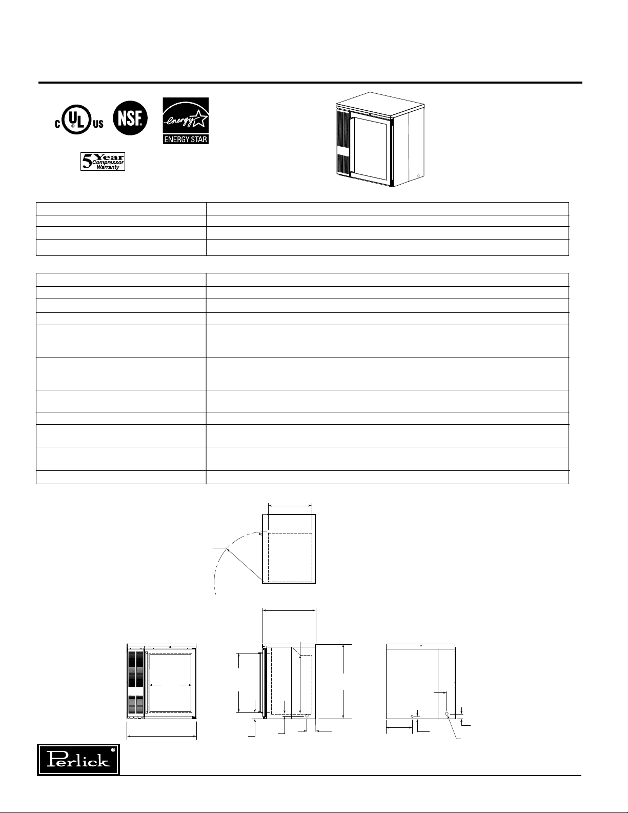
32”
[813]
19 7/8”
[505]
OPENING
27 1/2”
[699]
OPENING
2 3/4”
[70]
1 1/8”
[29]
4 3/16”
[94]
34 1/2”
[876]
27 1/4”
[692]
24 3/4”
[699]
23 3/16” R
[589]
20 1/8”
[511]
2 1/16”
[52]
12”
[305]
15/16”
[24]
4 1/16”
[103]
FRONT VIEW END VIEW
TOP VIEW
BACK VIEW
CORD EXIT
Sizes and Specifications, Single Door Cooler Series
DOOR FINISH MODel NUMBeRS
BLACK COATED SOLID CS32SB*
GLASS W/ BLACK COATED FRAME CS32SG
STAINLESS STEEL SOLID CS32SS
GLASS W/STAINLESS STEEL FRAME CS32ST
SPeCIFICATIONS
CONDENSING UNIT H.P. 1/6
AMPS 2.7
SHIP WT lbs. (kg) 210 (96)
CASE CAPACITY
Door Pan & Ceiling: High strength polystyrene. Door Sill: High strength polyethylene.
INTERIOR Floor Pan: Stainless steel. Walls: Galvanized steel. Includes pilasters, three
vinyl coated shelves and light.
Stainless steel top, back, sides and front. Galvanized bottom. Condensing unit grille
EXTERIOR stainless steel or black vinyl coated to match door finish. Full length stainless steel
handle and lock. Right hinged door standard from factory. Door hinging is field revers
REFRIGERATION
Adjustable temperature control. Self-defrosting.
VENTILATION Front ventilated.
ELECTRICAL
Contact Perlick-Milwaukee for other voltage/frequency requirements.
PLUMBING Evaporator condensate is removed automatically. Optional floor drain with
right end or 1” NPS out bottom come plugged from factory.
OPTIONAL ACCESSORIES • Leg Set • Caster Sets • Leg & Front Base Plate
* Energy Star approved. NOTE: This equipment is intended for the storage and display of non-potentially-hazardous bottled or canned products only.
(based on 12oz Long Neck bottle) 6
ible.
R-134a capillary tube-type. Aluminum fin and copper tube evaporator coil.
115 Volt, 60 Hz., 1 Phase AC. Furnished with three-prong, six foot NEMA 5-15P cord.
3
/4” NPT at
Form No. Z2266
Rev. 01.04.09
Perlick is committed to continuous improvement. Therefore, we reserve the right to change specifications without prior notice.
2
Page 3
Preparing the Cabinet for Use – Single Door Cooler Series
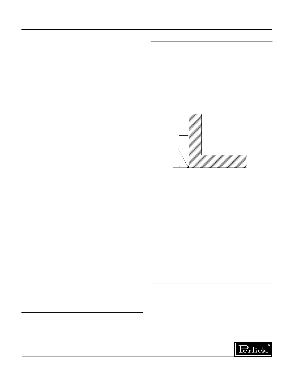
BEAD SILICON
SEALER (RTV)
FLOOR
CABINET
Parts List
■
(3) Shelves.
■
7 Watt Compact Fluorescent Light.
■
Shelf Clips.
Suggested Tools
■
#2 Phillips Screwdriver.
■
10” Crescent Wrench.
9
■
/16” Allen Wrench.
5
■
/16” and 3/8” Hex Socket.
■
Power Drill or Driver.
Plumbing
Condensate from the cooling coil is automatically
evaporated through a condensate pan located in the
condensing unit housing. Each unit is also equipped
with a floor drain located in the right rear corner of
the cabinet. The drain can be plumbed to an external
floor drain by connecting to the 3⁄4” NPT thread out
the side or the 1” NPS thread out the bottom. Both
drains ports come plugged from the factory and can
be removed if needed.
Placing the Cabinet
Push the cabinet into place using rollers when
necessary. Important: Proper air flow around the
condensing unit is necessary for efficient operation.
Never obstruct the air flow in and out of the
condensing unit.
For sanitation purposes, it may be necessary to
seal the base of the cabinet to the floor. This can be
accomplished by laying a bead of silicone sealant
between the base of the cabinet and the floor as
shown by the figure at below.
Leveling the Cabinet
Electrical
The cabinet must be connected to a separately
fused power source (see electrical specification
plate) and grounded in accordance with National
and Local Electrical Codes. Caution: Do not
attempt to operate the equipment on any other
power source than that listed on the Electrical
Specification plate.
Uncrating and Inspection
Remove all crating material before operating.
Carefully inspect cabinet for hidden damage. If
damage is discovered, file your claim immediately
with the transportation company. Perlick is
not responsible for damage in transit.
Installing Casters or Legs (Optional)
Attach four casters to the cabinet bottom; rigid casters at the rear and swivel casters on the front. Use
the supplied
machine screws.
1
/4”- 20 x 3/4” hex head self-tapping
When the cabinet is in place, check installation with
carpenter’s level. When perfectly level, accumulated
water will drain out. A slight pitch to the drain side
will not harm the cabinet. Water may accumulate if
cabinet is pitched to the opposite side.
Installing Base Plate (Optional)
Attach brackets to cabinet bottom in holes provided. Attach base plate to brackets. (See separate
instructions, provided with kit). When returning
cabinet to upright position, be careful not to bend
brackets.
WARNING!
To avoid compressor damage,after returning
cabinet to an upright position, let unit stand for
24 hours before plugging it in and running the unit.
Perlick is committed to continuous improvement. Therefore, we reserve the right to change specifications without prior notice.
3
Form No. Z2266
Rev. 01.04.09
Page 4

General Information – Single Door Cooler Series
Refrigeration and Temperature Control
The Single Door Cooler cabinet is equipped with
a heavy-duty refrigeration system designed to
automatically maintain a storage temperature of
approximately 38 degrees F.
Adjusting the Temperature
The temperature control is inside the cabinet on
the left-hand side of the evaporator fan panel
assembly. You will need a screwdriver to turn the
adjusting screw. Make small adjustments until the
desired temperature is achieved.
■
Colder Temperatures:
Turn the adjusting screw clockwise (to the right).
■
Warmer Temperatures:
Turn the adjusting screw counterclockwise
(to the left).
■
Temperature Control “OFF”:
Turn the adjusting screw completely counter clockwise to the “O” position until a click is
noted.
The condenser fan motor turns off and on with
the compressor. The evaporator fan motor is on
all the time.
NOTE:
Cabinet Temperatures lower than 34° will not
allow for proper defrosting of the evaporator coil. If
defrosting is necessary, turn the control knob to the
OFF position until coil is defrosted.
Cleaning the Cabinet
Use a mild detergent and water to clean the inside
and outside of the cabinet. Dry thoroughly. Never
use a scouring pad or abrasive cleanser.
NOTE: An industrial strength, commercial cleaner
can be used to clean the outside of painted
cabinets.
Cleaning the Condenser
Use a long handled, stiff brush to clean the dirt
from the front surface of the condenser. Keeping
the condenser free from dust and dirt will ensure
efficient operation.
CAUTION: Do not bend the fins while brushing the
front of the condenser.
Condenser
The condenser (located behind the front grille
cover) should be inspected every 30 days and
cleaned, if necessary.
Failure to keep the condenser clean will cause a
loss in condensing unit efficiency.
Form No. Z2266
Rev. 01.04.09
Perlick is committed to continuous improvement. Therefore, we reserve the right to change specifications without prior notice.
4
Page 5

8
9
10
12
2
3
4
5
11
1
7
6
15
22
17
14
13
16
Replacement Parts – Single Door Cooler Series
MODEL NOS. CS32
Item Description Part #’s
1 Compressor for R134a 63778
2 Condenser fan motor 63807
3 Condenser fan motor bracket 65166-1
4 Condenser fan blade 63808
5 Side panel 66215-1SS or 66215-1
6 Front grille 66210-8SS or 66210-8
7 Condenser 65528
8 Evaporator fan blade - 4” 63461
9 Evaporator fan motor C15239A
10 Evaporator assembly - complete 66295
11 Top assembly 66230-32
12 Temperature control 61271
13 Door assembly 66256-1
14 Magnetic door gasket 66237-4
15 Door sill 65500-1
16 Door handle 65305-1
17 Shelf 66265-1
22 Condensate pan 65473
Parts Not Shown on Drawing
Wiring Harness
Power cord 65531
Top evaporator 65532
Door lock with keys 63762
L & S line assembly 65529
Light bulb 63821
Light bulb guard 65525
Light switch 65535
Perlick is committed to continuous improvement. Therefore, we reserve the right to change specifications without prior notice.
5
Form No. Z2266
Rev. 01.04.09
Page 6

Wiring Diagram – Single Door Back Bar Cooler
JUNCTION
POINT
EVAPORATOR FAN
JUNCTION
POINTS
JUNCTION
POINTS
BLACK
BLACK
WHITE
RED
BLACK
WHITE
BLACK
NEMA–15P CORD
POWER CONNECTION
GREEN
WHITE
WHITE
GREE
N
RED
CONDENSER FAN
OVERLOAD
RELAY
COMPRESSOR
END VIEW
THERMOSTAT
WIRES FOAMED IN
CABINET WALL
LIGHT
Form No. Z2266
Rev. 01.04.09
Perlick is committed to continuous improvement. Therefore, we reserve the right to change specifications without prior notice.
6
Page 7

Door Switching Instructions – Single Door Cooler Series
Step #12 Step #11 Step #13
Step #14
Step #6
Step #7
Remove
these screws
Top Hinge Bracket
Bottom Hinge Bracket
Top Hinge Bracket
Bottom Hinge Bracket
Hinge Bushin
g
Tools Required
■
#3 Phillips Screwdriver.
1
■
/16” Allen Wrench.
■
Flathead Screwdriver
Right Hinged Door
(as shipped from factory)
Handle Styles
C31409-1
Not
65609-2
Reversible
65189
Operations to Perform on Cabinet
STEP 1:
Remove bottom hinge pin from
assembly.
65305-1
STEP 8:
Re-assemble hinge brackets to unit. Bottom right bracket
is assembled as the top left bracket. Top right bracket is
assembled as the bottom left bracket.
STEP 9:
Re-insert top hinge pin.
STEP 10:
Re-assemble lock rail from
STEP #3
Operations to Perform on Door
STEP 11:
Remove bottom
door hinge bracket
from door assembly and remove
door hinge bushing
from bracket.
Re-assemble door
hinge bracket to
previous position,
without bushing.
STEP 2:
Carefully lift and tilt out door
assembly from the unit and
set aside.
STEP 3:
Remove lock rail from
cabinet, requires removal of
four screws.
STEP 4:
Remove top hinge pin.
Remove top and bottom
hinge brackets from the unit.
STEP 5:
Remove hinge bushing from
bottom hinge bracket and
assemble to top hinge bracket.
STEP 6:
Taking care not to scratch the
surface, remove hole plugs from
the left hinge holes.
STEP 7:
Insert hole plugs into vacant right
hinge holes.
STEP 12:
Remove top door
hinge bracket from
door assembly and
assemble door
hinge bushing from
STEP 11 to bracket. Re-assemble door hinge bracket to
previous position with bushing attached.
STEP 13:
Door with full length SS handle:
There is no need to remove door handle. It will be
positioned correctly when door is reversed.
Door with SS pull tab or handle with wrap-
around bracket:
Remove the two screws mounting the handle and
reposition to appropriate location on the opposite
side of the door.
STEP 14:
Remove lock retainer and install on opposite end of door.
STEP 15:
What was the door top is now the door bottom. Carefully
lift the door onto the hinge brackets of the cabinet. The
two hinge bushings should meet. Reinsert the bottom
hinge pin to complete the door switching operation.
Perlick is committed to continuous improvement. Therefore, we reserve the right to change specifications without prior notice.
7
Form No. Z2266
Rev. 01.04.09
Page 8

Form No. Z2266
Rev. 01.04.09
8300 West Good Hope Road • Milwaukee, WI 53223 • Phone 414-353-7060 • Fax 414-353-7069
Toll Free 800-558-5592 • E-Mail: Perlick@Perlick.com • www.Perlick.com
 Loading...