

Page 1

INSTALLATION AND OPERATION INSTRUCTIONS
ICE CREAM CABINET
MODEL NOS.
8000
IMPORTANT INFORMATION
A Warranty card is enclosed that must be completed
and mailed to the Perlick Corporation to register the
warranty. If the card is not returned to Perlick, the
warranty period will begin from the date the
equipment is shipped from the factory.
This manual has been prepared to assist you in the
installation of your Ice Cream Cabinet and to
acquaint you with its operation and maintenance.
We dedicate considerable time to ensure that our
products provide the highest level of customer
satisfaction. If, however service is required, your
dealer can provide you with a list of qualified service
agents. For your own protection, never return merchandise for credit without our approval.
We thank you for selecting a Perlick product and
assure you of our continuing interest in your
satisfaction.
WARNING: When lifting, the full weight of the
cabinet must be supported. Lift from the cabinet
base and not from the top. Improper lifting can
result in severe damage to the cabinet.
Table of Contents
Specifications.........................................................2
Preparing the Cabinet for Use ...............................3
Uncrating and Inspecting .......................................3
Electrical................................................................3
Installation..............................................................3
General information...............................................3
Cooling System .....................................................3
Temperature Control..............................................3
Oiling......................................................................3
Cleaning.................................................................3
Installation Into a Countertop ................................4
Installation Into a Topshelf Underbar .....................5
Replacement Parts................................................6
Wiring Diagram......................................................7
8300 West Good Hope Road • Milwaukee, WI 53223 • Phone 414-353-7060 • Fax 414-353-7069
Toll Free 800-558-5592 • E-Mail: Perlick@Perlick.com • www.Perlick.com
Form No. Z2029A
Rev. 08.03.04
Page 2
Installation and Operating Instructions
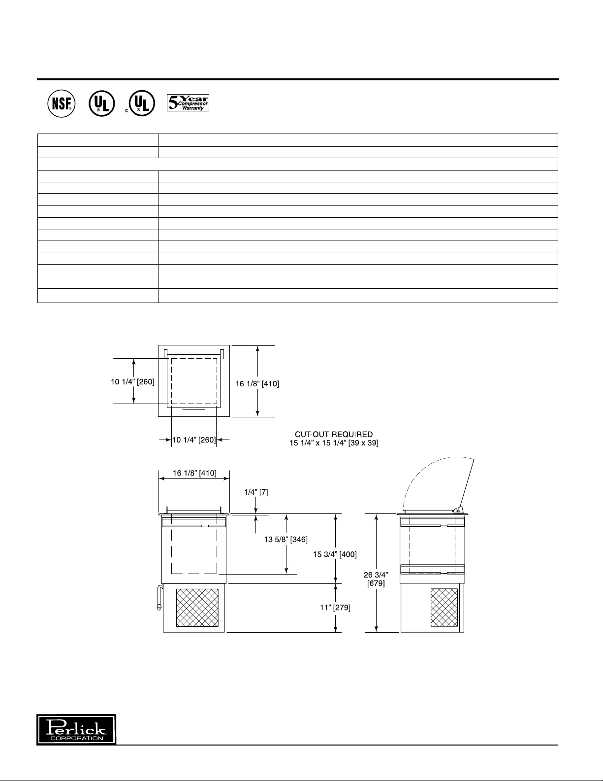
Sizes and Specifications, Ice Cream Cabinet
MODEL NOS. 8000
CAPACITY 3 Gallons
DIMENSIONS IN. [mm]
HEIGHT 26
WIDTH 16
DEPTH 16
SHIP WEIGHT lbs. (kg) 114 (52)
COMPRESSOR H.P.
AMPS 1.6
INTERIOR Well dimensions: 13
EXTERIOR 20 gauge stainless steel top and removable hinged door lid.
ELECTRICAL 115 Volt, 60 Hz., 1 Phase AC. Can also be used on 100 volt, 50 hz. 1 phase A.C. Furnished with
three-prong, six foot rubber cord.Contact Perlick for other electrical requirements.
REFRIGERANT and CHARGE R134a 5.5 oz. (142).
5
⁄8” [346] H x 101⁄4” [260] W x 101⁄4” [260] D.
3
⁄4” [680]
1
⁄8” [410]
1
⁄8” [410]
1
⁄5 h.p.
Form No. Z2029A
Rev. 08.03.04
Perlick is committed to continuous improvement. Therefore, we reserve the right to change specifications without prior notice.
2
Page 3

Preparing the Cabinet for Use – ICE CREAM CABINET
Uncrating and Inspection
Remove all crating material before operating this
cooler. Carefully inspect cabinet for hidden damage.
If damage is discovered, file your claim immediately
with the transportation company. Perlick is
not responsible for damage in transit.
Electrical
For specifications, see data plate located on the
cabinet. Also, see wiring diagram located in this
publication CAUTION: Do not use any other voltage
than is specified as serious damage will result.
Installation
IMPORTANT: The unit must NOT be totally
enclosed. There can be no restriction of air
circulation. The condenser at cabinet front must be
provided with a minimum opening the same size as
the condenser (100% open). The cabinet back must
have a minimum opening one and one-half times
the condenser size (150% open). Cabinet sides
have a minimum of two inches air space. Be sure to
provide access so front cover of drop-in ice cream
cabinet can be removed to clean the condenser.
After placing the cabinet into its initial operation,
allow about 24 hours for the cabinet to reach and
maintain proper temperature.
General information – Ice Cream Cabinet
Cooling System
This cabinet maintains temperatures from the cold
walls of the storage compartment. If excessive frost
accumulates on the walls, remove the plug from the
electrical outlet. Never use a sharp instrument to
break ice from the cabinet walls
Temperature Control
An adjustable temperature control is located on the
front of the unit near the condenser. It is factory set
at a normal operating temperature. Make adjustments to attain the desired temperature..
Oiling
The Hermetic (sealed) compressor and the condenser fan motor require no oiling.
Cleaning
Condenser
The condenser (located behind the front grille)
should be inspected every 60 days, and cleaned, if
necessary. Failure to keep the condenser clean will
cause a loss in condensing unit efficiency and
warmer cabinet temperatures.
Cabinet
Use a damp cloth with mild detergent and water to
clean the inside and outside of the cabinet. Dry
thoroughly.
0
Perlick is committed to continuous improvement. Therefore, we reserve the right to change specifications without prior notice.
3
Form No. Z2029A
Rev. 08.03.04
Page 4

Installation – Ice Cream Cabinet
Installing Into a Countertop
■
Cut a 151⁄4” [387mm] x 151⁄4” [387mm] square
hole in the countertop for the drop-in ice
cream cabinet.
Note: If C27522 Dipper Well and Faucet Kit are
also being installed, cut the two (2) round holes
required. (Access from bottom and sides is
needed to secure unit to countertop).
■
Apply 1⁄4” [6mm] diameter bead of sealant
supplied
(
shown in cross sections.
■
Insert ice cream cabinet into opening as shown,
making sure there are no voids in sealant where
top flange meets the countertop.
) to bottom outer edge of top flange as
■
From underneath, install the (3) hold down
clips in each upper track through slots as shown
in cross sections in approximate positions
shown below.
■
With uniform pressure, tighten screws in hold
down clips evenly to ensure a positive seal to
the countertop.
■
Remove exposed excess sealant from top
flange and countertop.
■
The faucet and drain are to be connected to
comply with local codes.
Form No. Z2029A
Rev. 08.03.04
Perlick is committed to continuous improvement. Therefore, we reserve the right to change specifications without prior notice.
4
Page 5

Installation – Ice Cream Cabinet
Installing Into a Topshelf Underbar
Stainless Steel Module
■
A151⁄4” [387mm] x 151⁄4” [387mm] square
hole has been provided in the top of the
TS24DC cabinet for the drop-in ice cream
cabinet.
■
Apply 1⁄4” [6mm] diameter bead of sealant
supplied
(
shown in cross sections.
■
Insert ice cream cabinet into opening as shown,
making sure there are no voids in sealant where
top flange meets the countertop.
) to bottom outer edge of top flange as
■
From underneath, install the (3) hold down
clips in tracks in approximate positions
shown below.
■
With uniform pressure, tighten screws in hold
down clips evenly to ensure a positive seal.
■
Remove exposed excess sealant from top
flange and workboard.
■
The faucet and drain are to be connected to
comply with local codes.
Perlick is committed to continuous improvement. Therefore, we reserve the right to change specifications without prior notice.
5
Form No. Z2029A
Rev. 08.03.04
Page 6

Replacement Parts – Ice Cream Cabinet
MODEL NOS. 8000 Serial Numbers Above 500,000
Description Part #’s
1
⁄5 h.p. condensing unit C22649
Complete condensing unit (#UM65HNR) 515301065
Compressor (Model EM65HNR) 513307090
5W Fan motor assembly 215315009
Condenser coil 15352019
Terminal board 219101538
Cover, overload relay 513504007
Lid assembly C29314A
Left hinge bracket C27506-1
Right hinge bracket C27505-1
Mounting stud C27073-1
Wiring harness C25195-1
Temperature control C27523
Breaker strip C25181-1
Back unit cover C29341
Front unit cover C29342
Hold-down clip C27476
Form No. Z2029A
Rev. 08.03.04
Perlick is committed to continuous improvement. Therefore, we reserve the right to change specifications without prior notice.
6
Page 7

Wiring Diagram – Ice Cream Cabinet
Perlick is committed to continuous improvement. Therefore, we reserve the right to change specifications without prior notice.
7
Form No. Z2029A
Rev. 08.03.04
Page 8

8300 West Good Hope Road • Milwaukee, WI 53223 • Phone 414-353-7060 • Fax 414-353-7069
Toll Free 800-558-5592 • E-Mail: Perlick@Perlick.com • www.Perlick.com
Perlick is committed to continuous improvement. Therefore, we reserve the right to change specifications without prior notice.
8
Form No. Z2029A
Rev. 08.03.04
 Loading...