

Page 1
INSTALLATION AND OPERATION INSTRUCTIONS
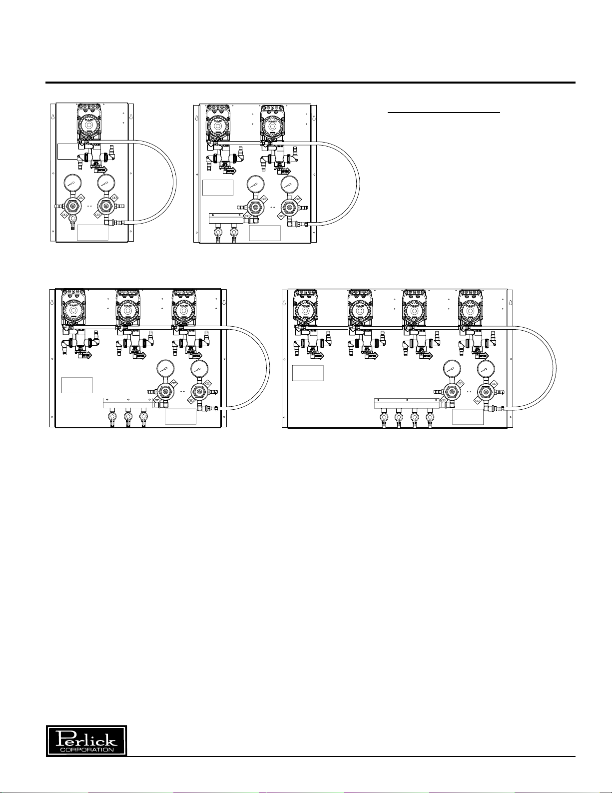
BEER PUMP PANELS
MODEL NO.
63134-1
63134-2
63134-3
63134-4
IMPORTANT INFORMATION
This manual has been prepared to assist you in the
operation of Perlick Beer Pump Panel System.
We dedicate considerable time to ensure that our
products provide the highest level of customer
satisfaction. If service is required, your dealer can
provide you with a list of qualified service agents. For
your own protection, never return merchandise for
credit without our approval.
We thank you for selecting a Perlick product and
assure you of our continuing interest in your
satisfaction.
8300 West Good Hope Road • Milwaukee, WI 53223 • Phone 414-353-7060 • Fax 414-353-7069
Toll Free 800-558-5592 • E-Mail: Perlick@Perlick.com • www.Perlick.com
Table of Contents
Installing the Panel ..............................................2
Panel Diagram.....................................................3
How to Operate the Beer Panel...........................4
Beer Pump Diagram............................................5
Cleaning Diagram................................................6
Cleaning Instructions ...........................................7
Winterizing a System with Beer Pumps...............7
Replacement Parts ..............................................7
Page 2
Installation – Beer Pump Panels
■ Use panel as a template to mark where holes
should be drilled on cooler wall.
(Note: Make sure panel is level and pumps are
in the vertical position).
9
■ Drill
/64”pilot holes in cooler wall. Use fasteners
provided in installation kit to mount the beer
pump panel to the cooler wall.
■ Push CO
Supply barbed inlet.
Position clamp over joint and tighten.
2 supply line over Keg Pressure
(See diagram on page 3).
(Note: A
safety Relief Valve should be installed between
supply tank and shut-off point on carbon dioxide
supply line. Relief setting depends on maximum
system pressures).
■ Push air or CO2 supply line over Beer Pump
Pressure barbed inlet.
3).
Position clamp over joint and tighten. If
(See diagram on page
using compressed air, make sure air supply
is clean and dry. Air must have a pressure
dew point of 30°F. or lower to ensure pumps
operate properly.
■ Push beer line (from trunk housing) over barbed
Liquid outlet on flow reversal valve.
(see diagram on page 3)
. Position clamp over
joint and tighten.
■ Push connector hose over Liquid inlet on beer
pump inlet fitting.
(See diagram on page 3)
.
Position clamp over joint and tighten. (Note:
Connector hose should not exceed 10 feet in
length)
.
■ Install washer into hex nut on opposite end of
connector hose. Connect to top threaded fitting
of Perlick Smart Coupler.
■ Cut a piece of CO2 tubing and push one end
onto barbed CO
page3)
. Position clamp over joint and tighten.
2 outlet.
(See diagram on
Push the other end over the barbed gas inlet on
the Perlick Smart Coupler. Position clamp over
joint and tighten.
CAUTION: IF USING CO
2 AS A
PRESSURE SUPPLY FOR PUMPS,
PUMP EXHAUST MUST BE VENTED
TO A WELL VENTILATED AREA TO
AVOID POSSIBLE ASPHYXIATION.
Perlick is committed to continuous improvement. Therefore, we reserve the right to change specifications without prior notice.
2
Page 3
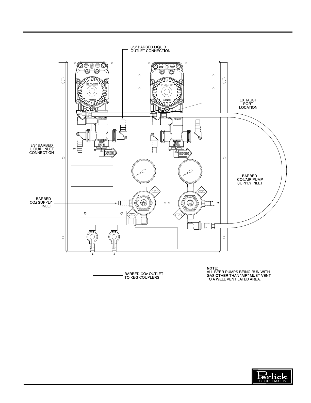
Diagram – Beer Pump Panel Diagram
Perlick is committed to continuous improvement. Therefore, we reserve the right to change specifications without prior notice.
3
Page 4

How to Operate – Beer Pump Panels
■ Adjust primary CO2 regulator by turning
adjusting screw counterclockwise until it turns
freely, then turn hand valve counterclockwise on
CO2 cylinder to the fully open position. Next, turn
regulator adjusting screw clockwise until desired
pressure is reached.
Note: If CO
2 is only being used for keg-
applied pressure, adjust to approximately
40 psig. If CO
2 is being used to supply
beer pumps, adjust to the required system
pressure plus an additional 15 psig.
■ Adjust the air compressor output regulator
pressure to a minimum of 15 psig. greater than
the maximum required system pressure required
to operate the beer pumps. Maximum setting
100 psig.
■ Adjust secondary CO2 regulator which
supplies the keg pressure located on the
beer pump panel to the proper pressure
setting. Setting depends on beer brand and
temperature. Desired goal is to maintain the
natural carbonation in the beer. Open the shutoff valves.
■ Ensure the Probe Valve on the Perlick Smart
Coupler is in closed position.
See figure 1
.
Ensure the Beer Pump Flow Reversal/Dispense
handle is in the dispense position. Adjust the
Secondary Air/ CO
2 regulator located on the
beer pump panel to a minimum operating
pressure of 10 psig.
■ Connect the coupler to a regulated water supply
with pressure less than 30 psig. Note: Pump
damage may occur with pressure higher
than 30 psig.
■ Open the water supply. Then open probe valve
on Perlick Smart coupler to the 45° position.
See figure 2.
The beer pump will slowly pump
up the beer line in the trunk housing to set psig.
Note: If pump continues to run for longer than
expected, check lines for possible leaks at one
or more of the connections.
■ Gradually increase secondary regulator
pressure to the designed system pressure to
achieve a flow rate of one gallon per minute
from the dispensing head. Note: Maximum
beer pump operating pressure is 90 psig.
■ Open dispensing head faucet to purge air
trapped within the tubing.
■ Check all gas and liquid line fittings and
connections for leaks.
■ Close probe valve on Perlick Smart Coupler.
(See figure 1)
and disconnect coupler from
regulated water source.
■ Clean beer system. After cleaning and rinsing
the system, make sure the beer line is full of
cold water (beer dispensing from warm beer
lines will be poor quality).
■ Tap fresh keg with Perlick Smart Coupler. Open
dispensing head faucet until clear beer flows.
Smart Coupler Probe Valve Lever Positions
Figure 1
Closed Position
Perlick is committed to continuous improvement. Therefore, we reserve the right to change specifications without prior notice.
45° or Cleaning Position
Figure 2
Figure 3
Open Position
4
Page 5

Diagram #2 – Beer Pump
Perlick is committed to continuous improvement. Therefore, we reserve the right to change specifications without prior notice.
5
Page 6

Diagram #3 – Cleaning Diagram
Perlick is committed to continuous improvement. Therefore, we reserve the right to change specifications without prior notice.
6
Page 7

Cleaning Instructions
General Information
■ The cleaning of beer lines with the new integral
flow reversal feature incorporated into the
Perlick Beer Pump gives the line cleaner
numerous configurations for line cleaning.
Although the Perlick Beer Pump can be used as
an in-line pump for moving the solution from the
coupler to the faucet due to its capability of
working with negative lift, the following is the
recommended method for cleaning beer lines
with the Perlick Beer Pump with integral flow
reversal installed.
Cleaning from the Tap/Faucet End
■ Disconnect Perlick Smart Couplers from the
kegs following Smart Coupler instructions.
■ Couple the two Smart Couplers together using
Dual Cleaning Adapters (43681) which have a
pin of sufficient length to lift the internal slide
within the Smart Coupler to allow proper flow.
■ Determine which sets of lines will be cleaned
together and rotate the Dispense/Reverse Flow
handle to the Reverse Flow position on the line
which fluid will be pushed back from the
Tap/Faucet.
■ Rotate the Smart Coupler Valve Handle to the
Clean position on both couplers (See Smart
Coupler Instructions).
■ Relieve the line pressure by opening the
faucets.
■ Remove the faucet from the line, which will
have the Beer Line Cleaner pump connected
to it.
■ Connect Beer Line Cleaner pump to the shank.
■ Follow standard line cleaning procedures.
Perlick recommendes that the lines first be
flushed with clean warm water (Water temperature not to exceed 100°F). Mix line-cleaning
solution per the manufacturer’s directions.
Circulate the solution thoroughly (Time for
circulation dependent on the length of the
system and pump capabilities). Rinse the lines
using clean cold water (Ensure all line cleaning
solution has been removed from the lines to
prevent hazardous results).
■ Disconnect line-cleaning pump.
■ Remove and clean taps and couplers.
■ Reconnect taps and couplers and return Beer
Pump Dispense/Reverse Flow valve to the
Dispense position.
■ Reconnect couplers to keg and open dispensing
head faucets until clear beer flows.
Winterizing Systems with Beer Pumps
■ When a beer system with beer pumps will be
shut down for an extended period, clean the
system thoroughly. After completing the rinsing
step, prepare a mixture of 50% food grade
Glycerine and 50% water. Load the lines with
this mixture and make sure both ends of the
system are closed. Glycerine/water mixture
should remain in the lines for the duration of
the shutdown period.
Replacement Parts
44...................Air valve
40115 .............Regulator body
40129.............Regulator body
43553A...........Regulator repair kit
63705.............Beer pump, Flo-Jet, w/CO
63706.............Flow reversal valve
63707.............Elbow, flow reversal, 2/bag
63708.............Fitting, tee, gas, barbed
check valve
63709..............Fitting, elbow, gas, barbed
check valve
63710.............Beer pump, Flo-Jet, w/CO
2
elbow
1
/4” with
1
4” with
/
2
tee
Perlick is committed to continuous improvement. Therefore, we reserve the right to change specifications without prior notice.
7
Page 8

8300 West Good Hope Road • Milwaukee, WI 53223 • Phone 414-353-7060 • Fax 414-353-7069
Toll Free 800-558-5592 • E-Mail: Perlick@Perlick.com • www.Perlick.com
Perlick is committed to continuous improvement. Therefore, we reserve the right to change specifications without prior notice.
Form No. Z2149A
Rev. 08.24.04
 Loading...