

Page 1

Perkins Phaser and 1000 Series
Contents
Contents
EXIT
Contents
EXIT
Contents
WORKSHOP MANUAL
Phaser 4 and 6 cylinder diesel engines for
automotive applications
1000 Series 4 and 6 cylinder diesel engines for
agricultural and industrial application
Publication TPD 1312E, Issue 1.
(c) Perkins Group Limited 1995, all rights reserved.
Published 1 April 1995 by Technical Publications,
Perkins International Limited, Peterborough PE1 5NA, England
Perkins Phaser/1000 Series, April 1995 00.01
Page 2
Amendment status
Issue
number
1
e
scription Date
D
This issue, number TPD 1312E, includes information from earlier
issue TPD 0191 1301 and TPD 0391 1266 and new information
about:
The Fastram piston, composite rocker cover, dampers, belt driven
coolant pumps and different timing case, flame ring and partially
finished liners, KSB cold starting aid, Stanadyne and Lucas DP200
fuel injection pumps, turbocharger and faults, closed engine
breather, quick release fuel filters, the idler gear of the lubricating
oil pump, intercoolers, twin fuelled starting aids, Bendix compressor
and lift equipment.
Also new information about:
The Bosch EPVE locked fuel injection pump, atomisers and fuel
injection pump codes, data and dimensions
April 1995
00.02 Perkins Phaser/1000 Series, April 1995
Page 3

Contents
General information. . . . . . . . . . . . . . . . . . . . . . . . . . 10
Specifications. . . . . . . . . . . . . . . . . . . . . . . . . . . . . . 11
SERVICE OPERATIONS
Cylinder head assembly. . . . . . . . . . . . . . . . . . . . . . 12
Piston and connecting rod assemblies. . . . . . . . . . . . 13
Crankshaft assembly. . . . . . . . . . . . . . . . . . . . . . . . . 14
Timing case and drive assembly. . . . . . . . . . . . . . . . 15
Cylinder block assembly. . . . . . . . . . . . . . . . . . . . . . 16
Engine timing. . . . . . . . . . . . . . . . . . . . . . . . . . . . . . 17
Aspiration system. . . . . . . . . . . . . . . . . . . . . . . . . . . 18
Lubrication system. . . . . . . . . . . . . . . . . . . . . . . . . . 19
Fuel system. . . . . . . . . . . . . . . . . . . . . . . . . . . . . . . 20
Cooling system. . . . . . . . . . . . . . . . . . . . . . . . . . . . . 21
Flywheel and housing. . . . . . . . . . . . . . . . . . . . . . . . 22
Electrical equipment. . . . . . . . . . . . . . . . . . . . . . . . . 23
Auxiliary equipment. . . . . . . . . . . . . . . . . . . . . . . . . . 24
List of special tools. . . . . . . . . . . . . . . . . . . . . . . . . . 25
Perkins Phaser/1000 Series, April 1995 00.03
Page 4

General information10
Introduction. . . . . . . . . . . . . . . . . . . . . . . . . . . . . . . . . . . . . . . . . . . . . . . . . .10.02
Engine views. . . . . . . . . . . . . . . . . . . . . . . . . . . . . . . . . . . . . . . . . . . . . . . .10.03
Engine identification. . . . . . . . . . . . . . . . . . . . . . . . . . . . . . . . . . . . . . . . . . .10.04
Safety precautions
Safety. . . . . . . . . . . . . . . . . . . . . . . . . . . . . . . . . . . . . . . . . . . . . . . . . .10.05
Engine lift equipment. . . . . . . . . . . . . . . . . . . . . . . . . . . . . . . . . . . . . . . . . . .10.06
Asbestos joints. . . . . . . . . . . . . . . . . . . . . . . . . . . . . . . . . . . . . . . . . . . . . . .10.07
Viton seals. . . . . . . . . . . . . . . . . . . . . . . . . . . . . . . . . . . . . . . . . . . . . . . . . .10.08
Powerpart consumable products. . . . . . . . . . . . . . . . . . . . . . . . . . . . . . . .10.09
Perkins Phaser/1000 Series, April 1995 10.01
Page 5

10 GENERAL INFORMATION
Introduction
This workshop manual has been designed to
provide assistance in the service and overhaul of
Perkins Phaser and 1000 Series engines.
Most of the general information which is
included in the relevant User's Handbook
(sections 1 to 9) has not been repeated in this
workshop manual and the two publications
should be used together.
Where the information applies only to certain engine
types, this is indicated in the text.
The details of some operations will be different
according to the type of fuel injection pump which
is fitted. The specific pump type used can be found
by reference to the manufacturer's identification
plate on the pump body but, generally, the type of
pump fitted is as shown below.
Lucas DPA, DPS and DP200 Series
Bosch EPVE and MW
Stanadyne DB2 and DB4
When reference is made to the "left" or "right" side
of the engine, this is as seen from the flywheel end
of the engine.
Special tools have been made available and a list of
these is given in section 25. Reference to the
relevant special tools is also made at the beginning
of each operation.
Data and dimensions are included at the end of
each section.
Read and remember the "Safety precautions".
They are given for your protection and must be
used at all times.
Danger is indicated in the text by two methods:
Warning! This indicates that there is a possible
danger to the person.
Caution: This indicates that there is a possible
danger to the engine.
Note: Is used where the information is important,
but there is not a danger.
10.02 Perkins Phaser/1000 Series, April 1995
Page 6
GENERAL INFORMATION 10
PA314
PA315
Perkins Phaser/1000 Series, April 1995 10.03
Page 7
10 GENERAL INFORMATION
aaa
aaa
aaa
aaa
aaa
aaa
aaa
Engine identification
The Perkins Phaser and 1000 Series engines have
been designed for specific applications, as shown
below:
• Phaser for automotive applications.
• 1000 Series for agricultural and industrial
applications
Each series consists of both four and six cylinder
engines, each of which will have four basic engine
types - naturally aspirated, compensated,
turbocharged and turbocharged/intercooled.
There are different models in each series.
Phaser engines are named according to their
approximate power output, for example:
Phaser\110T - four cylinder engine rated at 106 bhp
"T" indicates that the engine is turbocharged.
Phaser\210Ti - six cylinder engine rated at 210 bhp
"Ti" indicates that the engine is turbocharged and
intercooled.
1000 Series engines are identified by a system of
numbers and letters, for example:
1006-6TW - six cylinder engine of six litres
"TW" indicates that the engine is turbocharged and
intercooled.
In this workshop manual, the different engine types
are indicated by their code letters. These are the
first two letters of the engine number as indicated
below:
1
2
PA043
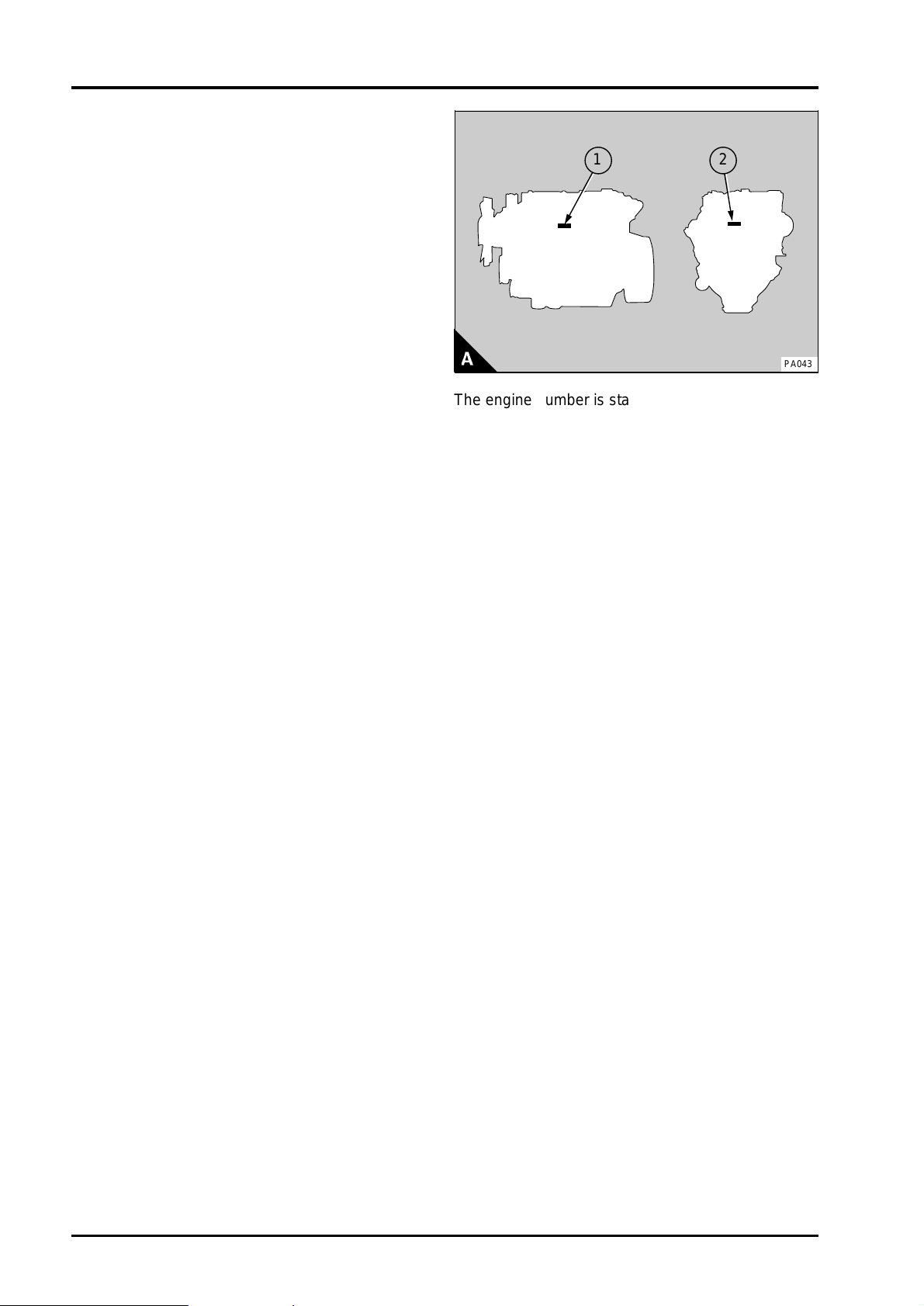
The engine number is stamped on a label which is
fastened to the left side (A1) or rear (A2) of the
cylinder block. An example of an engine number is
AB30126U510256N.
Further information about the engine number
system can be found in the relevant user's
handbook.
Note: If you need parts, service or information for
your engine, you must give the complete engine
number to your Perkins distributor.
Code letters Engine type
AA Four cylinder, naturally aspirated
AB Four cylinder, turbocharged
AC Four cylinder, compensated
AD Four cylinder,
turbocharged/intercooled
AE Four cylinder,
turbocharged/intercooled designed
to conform to the USA emission
legislation
AG Four cylinder, naturally aspirated
with belt driven water pump.
AH Four cylinder, turbocharged with
belt driven water pump.
YA Six cylinder, naturally aspirated.
YB Six cylinder, turbocharged.
YC Six cylinder, compensated.
YD Six cylinder,
turbocharged/intercooled.
YE Six cylinder,
turbocharged/intercooled designed
to conform to the USA emission
legislation
10.04 Perkins Phaser/1000 Series, April 1995
Page 8

GENERAL INFORMATION 10
General safety precautions
These safety precautions are important. You
must refer also to the local regulations in the
country of use. Some items only refer to specific
applications.
• Only use these engines in the type of application
for which they have been designed.
• Do not change the specification of the engine.
• Do not smoke when you put fuel in the tank.
• Clean away fuel which has been spilt. Material
which has been contaminated by fuel must be
moved to a safe place.
• Do not put fuel in the tank while the engine runs
(unless it is absolutely necessary).
• Do not clean, add lubricating oil, or adjust the
engine while it runs (unless you have had the
correct training; even then extreme care must be
used to prevent injury).
• Do not make adjustments that you do not
understand.
• Ensure that the engine does not run in a location
where it can cause a concentration of toxic
emissions.
• Other persons must be kept at a safe distance
while the engine or auxiliary equipment is in
operation.
• Do not permit loose clothing or long hair near
moving parts.
• Keep away from moving parts during engine
operation
be seen clearly while the engine runs.
• Do not operate the engine if a safety guard has
been removed.
• Do not remove the filler cap of the cooling
system while the engine is hot and while the
coolant is under pressure, because dangerous
hot coolant can be discharged.
• Do not use salt water or any other coolant which
can cause corrosion in the closed circuit of the
cooling system.
• Do not allow sparks or fire near the batteries
(especially when the batteries are on charge)
because the gases from the electrolyte are highly
flammable. The battery fluid is dangerous to the
skin and especially to the eyes.
• Disconnect the battery terminals before a repair
is made to the electrical system.
• Only one person must control the engine.
• Ensure that the engine is operated only from the
control panel or from the operators position.
• If your skin comes into contact with high-
pressure fuel, obtain medical assistance
immediately.
. Warning! Some moving parts cannot
• Diesel fuel and lubricating oil (especially used
lubricating oil) can damage the skin of certain
persons. Protect your hands with gloves or a
special solution to protect the skin.
• Do not wear clothing which is contaminated by
lubricating oil. Do not put material which is
contaminated with oil into the pockets of clothing.
• Discard used lubricating oil in a safe place to
prevent contamination.
• Ensure that the control lever of the transmission
drive is in the "out-of-drive" position before the
engine is started.
• Use extreme care if emergency repairs must be
made in adverse conditions.
• The combustible material of some components
of the engine (for example certain seals) can
become extremely dangerous if it is burned.
Never allow this burnt material to come into
contact with the skin or with the eyes.
• Read and use the instructions relevant to lift
equipment which are given on page 10.06.
• Always use a safety cage to protect the operator
when a component is to be pressure tested in a
container of water. Fit safety wires to secure the
plugs which seal the hose connections of a
component which is to be pressure tested.
• Do not allow compressed air to contact your
skin. If compressed air enters your skin, obtain
medical help immediately.
• Turbochargers operate at high speed and at high
temperatures. Keep fingers, tools and debris
away from the inlet and outlet ports of the
turbocharger and prevent contact with hot
surfaces.
• Fit only genuine Perkins parts.
Perkins Phaser/1000 Series, April 1995 10.05
Page 9
10 GENERAL INFORMATION
a
a
a
a
a
a
aaa
aaa
aaa
Safety
Engine lift equipment
The maximum weight of the engine without coolant,
lubricant or a gearbox fitted will vary for different
applications. It is recommended that lift equipment
of the minimum capacity listed below is used:
Four cylinder engines . . . . . . 500 Kg (1100 lbs)
Six cylinder engines . . . . . . . 600 Kg (1320 lbs)
Before the engine is lifted:
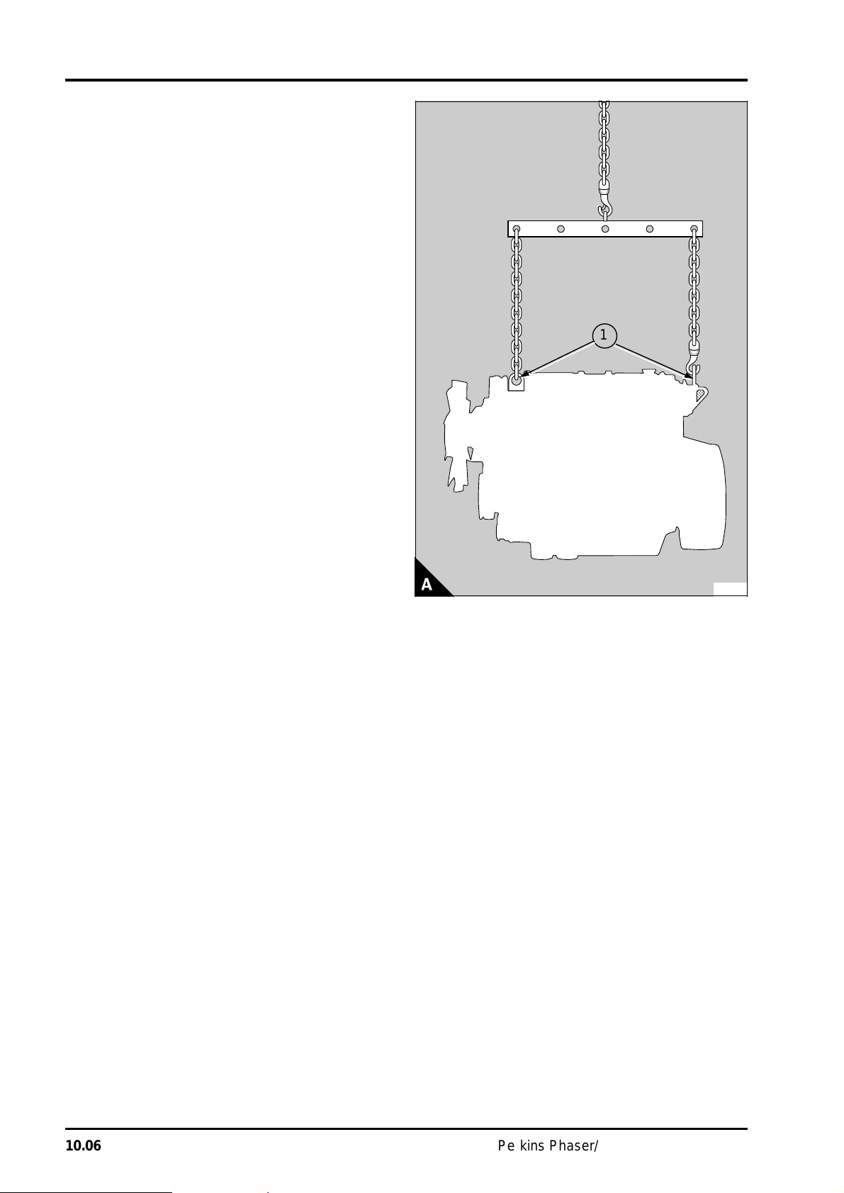
• Always use lift equipment of the approved type
and of the correct capacity to lift the engine. It is
recommended that lift equipment of the type
shown in (A) is used, to provide a vertical lift
directly above the engine lift brackets (A1).
Never use a single lift bracket to raise an engine.
• Check the engine lift brackets for damage and
that they are secure before the engine is lifted.
The torque for the setscrews for the engine lift
brackets is 44 Nm (33 lbf ft) 4,5 kgf m.
• To Prevent damage to the rocker cover, ensure
that there is clearance between the hooks and
the rocker cover.
• Use lift equipment or obtain assistance to lift
heavy engine components such as the cylinder
block, cylinder head, balancer unit, flywheel
housing, crankshaft and flywheel.
1
PA044
10.06 Perkins Phaser/1000 Series, April 1995
Page 10
Safety
Asbestos joints
Some joints and gaskets contain compressed
asbestos fibres in a rubber compound or in a metal
outer cover. The "white" asbestos (Chrysotile)
which is used is a safer type of asbestos and the
risk of damage to health is extremely small.
• The risk of asbestos from joints occurs at their
edges or if a joint is damaged when a component
is removed or if a joint is removed by abrasives.
• To ensure that the risk is kept to a minimum, the
precautions given below must be applied when
an engine which has asbestos joints is
dismantled or assembled.
• Work in an area with good ventilation.
• Do not smoke.
• Use a hand scraper to remove the joints - do not
use a rotary wire brush.
• Ensure that the joint to be removed is wet with
oil or water to contain loose particles.
• Spray all asbestos debris with water and put it in
a closed container which can be sealed for safe
disposal.
GENERAL INFORMATION 10
PG008
Perkins Phaser/1000 Series, April 1995 10.07
Page 11

10 GENERAL INFORMATION
Safety
Viton seals
Some seals used in engines and in components
fitted to engines are made of Viton.
Viton is used by many manufacturers and is a safe
material under normal conditions of operation.
If Viton is burned, a product of this burnt material is
an acid which is extremely dangerous. Never allow
this burnt material to come into contact with the
skin or with the eyes.
If it is necessary to come into contact with
components which have been burnt, ensure that
the precautions which follow are used:
• Ensure that the components have cooled.
• Use Neoprene gloves and discard the gloves
safely after use.
• Wash the area with calcium hydroxide solution
and then with clean water.
• Disposal of components and gloves which are
contaminated must be in accordance with local
regulations.
If there is contamination of the skin or eyes, wash
the affected area with a continuous supply of clean
water or with calcium hydroxide solution for 15-60
minutes. Obtain immediate medical attention.
10.08 Perkins Phaser/1000 Series, April 1995
Page 12

GENERAL INFORMATION 10
POWERPART consumable products
Perkins have made available the products
recommended below in order to assist in the
correct operation, service and maintenance of your
engine and your machine. The instructions for the
use of each product are given on the outside of
each container. These products are available from
your Perkins distributor.
POWERPART Antifreeze
Protects the cooling system against frost and
corrosion. Part number 1 litre 21825166 or 5 litres
21825167, see the User's Handbook.
POWERPART Easy Flush
Cleans the cooling system. Part number 2182501
POWERPART Jointing compound
Universal jointing compound which seals joints.
Currently Hylomar. Part number 1861155 or
1861117.
POWERPART Silicone rubber sealant
Silicone rubber sealant which prevents leakage
through gaps. Currently Hylosil. Part number
1861108.
POWERPART Lay-Up 1
A diesel fuel additive for protection against
corrosion. Part number 1772204, see the User's
Handbook.
POWERPART Studlock
To permanently retain large fasteners and studs.
Currently Loctite 270. Part number 21820270.
POWERPART Liquid gasket
To seal flat faces of components where no joint is
used. Especially suitable for aluminium
components. Currently Loctite 518. Part number
21820518
POWERPART Threadlock (hydraulic/pneumatic)
To retain and seal pipe connections with fine
threads. Especially suitable for hydraulic and
pneumatic systems. Currently Loctite 542. Part
number 2180542
POWERPART Threadlock (pipe)
To retain and seal pipe connections with coarse
threads. Pressure systems can be used
immediately. Currently Loctite 575. Part number
21820575.
POWERPART Retainer (oil tolerant)
To retain components which have a transition fit.
Currently Loctite 603. Part number 21820603.
POWERPART Retainer (high strength)
To retain components which have an interference
fit. Currently Loctite 638. Part number 21820638.
POWERPART Lay-Up 2
Protects the inside of the engine and of other
closed systems. Part number 1762811, see the
User's Handbook.
POWERPART Lay-Up 3
Protects outside metal parts. Part number 1734115,
see the User's Handbook.
POWERPART Chisel
Allows easy removal of old gaskets and joints.
Currently Loctite Chisel. Part number 21825163.
POWERPART Repel
Dries damp equipment and gives protection against
corrosion. Passes through dirt and corrosion to
lubricate and to assist removal of components.
Currently Loctite Repel. Part number 21825164.
POWERPART Threadlock
To retain small fasteners where easy removal is
necessary. Currently Loctite 222e. Part number
21820222.
POWERPART Nutlock
To retain and seal threaded fasteners and cup
plugs where easy removal is necessary.
Currently Loctite 242e. Part number 21820242
Perkins Phaser/1000 Series, April 1995 10.09
Page 13

Specifications11
Basic engine data. . . . . . . . . . . . . . . . . . . . . . . . . . . . . . . . . . . . . . .11A
Recommended torque tensions. . . . . . . . . . . . . . . . . . . . . . . . . . . . .11B
Perkins Phaser/1000 Series, April 1995 11.01
Page 14

Basic engine data11A
Basic engine data. . . . . . . . . . . . . . . . . . . . . . . . . . . . . . . . . . . . . . . . . . . 11A.02
Perkins Phaser/1000 Series, April 1995 11A.01
Page 15

11A BASIC ENGINE DATA
Basic engine data
Number of cylinders:
- AA, AB, AC, AD, AE, AG, AH . . . . . . . . . . . . . . . . . . . . . . . . . . . . . . . . . . . . . . . . . . . . . . . . . . .4
- YA, YB, YC, YD, YE . . . . . . . . . . . . . . . . . . . . . . . . . . . . . . . . . . . . . . . . . . . . . . . . . . . . . . . . . 6
Cylinder arrangement . . . . . . . . . . . . . . . . . . . . . . . . . . . . . . . . . . . . . . . . . . . . . . . . . . . . . . In-line
Cycle . . . . . . . . . . . . . . . . . . . . . . . . . . . . . . . . . . . . . . . . . . . . . . . . . . . . . . . . . . . . . Four stroke
Direction of rotation . . . . . . . . . . . . . . . . . . . . . . . . . . . . . . . . . . . . . . . . . . Clockwise from the front
Induction system:
- AA, AG, YA . . . . . . . . . . . . . . . . . . . . . . . . . . . . . . . . . . . . . . . . . . . . . . . . . . . Naturally aspirated
- AB, AH, YB . . . . . . . . . . . . . . . . . . . . . . . . . . . . . . . . . . . . . . . . . . . . . . . . . . . . . . . Turbocharged
- AC, YC . . . . . . . . . . . . . . . . . . . . . . . . . . . . . . . . . . . . . . . . . . . . . . . . . . . . Altitude compensated
- AD, AE, YD, YE . . . . . . . . . . . . . . . . . . . . . . . . . . . . . . . . . . . . . . . . . . . Turbocharged/intercooled
Combustion system . . . . . . . . . . . . . . . . . . . . . . . . . . . . . . . . . . . . . . . . . . . . . . . . . Direct injection
Nominal bore . . . . . . . . . . . . . . . . . . . . . . . . . . . . . . . . . . . . . . . . . . . . . . . . . . . 100 mm (3.937 in)
Stroke . . . . . . . . . . . . . . . . . . . . . . . . . . . . . . . . . . . . . . . . . . . . . . . . . . . . . . . . 127 mm (5.000 in)
Compression ratio:
- AA, AG, YA . . . . . . . . . . . . . . . . . . . . . . . . . . . . . . . . . . . . . . . . . . . . . . . . . . . . . . . . . . . . 16.5:1
- Certain YA engines . . . . . . . . . . . . . . . . . . . . . . . . . . . . . . . . . . . . . . . . . . . . . . . . . . . . . . 17.5:1
- AB, AC, AD, AH, YB, YC, YD . . . . . . . . . . . . . . . . . . . . . . . . . . . . . . . . . . . . . . . . . . . . . . . 16.0:1
- AE, YE . . . . . . . . . . . . . . . . . . . . . . . . . . . . . . . . . . . . . . . . . . . . . . . . . . . . . . . . . . . . . . . 17.5:1
- Certain AD engines . . . . . . . . . . . . . . . . . . . . . . . . . . . . . . . . . . . . . . . . . . . . . . 17.25:1 or 17.5:1
Cubic capacity:
Four cylinder engines . . . . . . . . . . . . . . . . . . . . . . . . . . . . . . . . . . . . . . . . . . . . . . . 4 litres (243 in
Six cylinder engines . . . . . . . . . . . . . . . . . . . . . . . . . . . . . . . . . . . . . . . . . . . . . . . . 6 litres (365 in
Firing order:
Four cylinder engines . . . . . . . . . . . . . . . . . . . . . . . . . . . . . . . . . . . . . . . . . . . . . . . . . . . . 1, 3, 4, 2
Six cylinder engines . . . . . . . . . . . . . . . . . . . . . . . . . . . . . . . . . . . . . . . . . . . . . . . . . 1, 5, 3, 6, 2, 4
Valve tip clearance (cold):
- Inlet . . . . . . . . . . . . . . . . . . . . . . . . . . . . . . . . . . . . . . . . . . . . . . . . . . . . . . . . 0,20 mm (0.008 in)
- Exhaust . . . . . . . . . . . . . . . . . . . . . . . . . . . . . . . . . . . . . . . . . . . . . . . . . . . . . 0,45 mm (0.018 in)
Lubricating oil pressure (minimum at maximum engine speed and
normal engine temperature):
- Engines without piston cooling jets . . . . . . . . . . . . . . . . . . . . . . . . . 207 kpa (30 lbf/in
- Engines with piston cooling jets . . . . . . . . . . . . . . . . . . . . . . . . . . . . 280 kpa (40 lbf/in2) 2,8 kgf/cm
2
) 2,1 kgf/cm
3
)
3
)
2
2
11A.02 Perkins Phaser/1000 Series, April 1995
Page 16

Recommended torque tensions11B
Cylinder head assembly. . . . . . . . . . . . . . . . . . . . . . . . . . . . . . . . . . . . . . 11B.02
Pistons and connecting rod assemblies. . . . . . . . . . . . . . . . . . . . . . . . . . . 11B.02
Crankshaft assembly. . . . . . . . . . . . . . . . . . . . . . . . . . . . . . . . . . . . . . . . . 11B.02
Timing case and drive assembly. . . . . . . . . . . . . . . . . . . . . . . . . . . . . . . . 11B.03
Cylinder block. . . . . . . . . . . . . . . . . . . . . . . . . . . . . . . . . . . . . . . . . . . . . . 11B.03
Aspiration system. . . . . . . . . . . . . . . . . . . . . . . . . . . . . . . . . . . . . . . . . . . 11B.03
Fuel system. . . . . . . . . . . . . . . . . . . . . . . . . . . . . . . . . . . . . . . . . . . . . . . 11B.03
Lubrication system. . . . . . . . . . . . . . . . . . . . . . . . . . . . . . . . . . . . . . . . . . 11B.04
Cooling system. . . . . . . . . . . . . . . . . . . . . . . . . . . . . . . . . . . . . . . . . . . . . 11B.04
Flywheel and housing. . . . . . . . . . . . . . . . . . . . . . . . . . . . . . . . . . . . . . . . 11B.04
Electrical equipment. . . . . . . . . . . . . . . . . . . . . . . . . . . . . . . . . . . . . . . . . 11B.04
Auxiliary equipment. . . . . . . . . . . . . . . . . . . . . . . . . . . . . . . . . . . . . . . . . . 11B.05
Perkins Phaser/1000 Series, April 1995 11B.01
Page 17
11B RECOMMENDED TORQUE TENSIONS
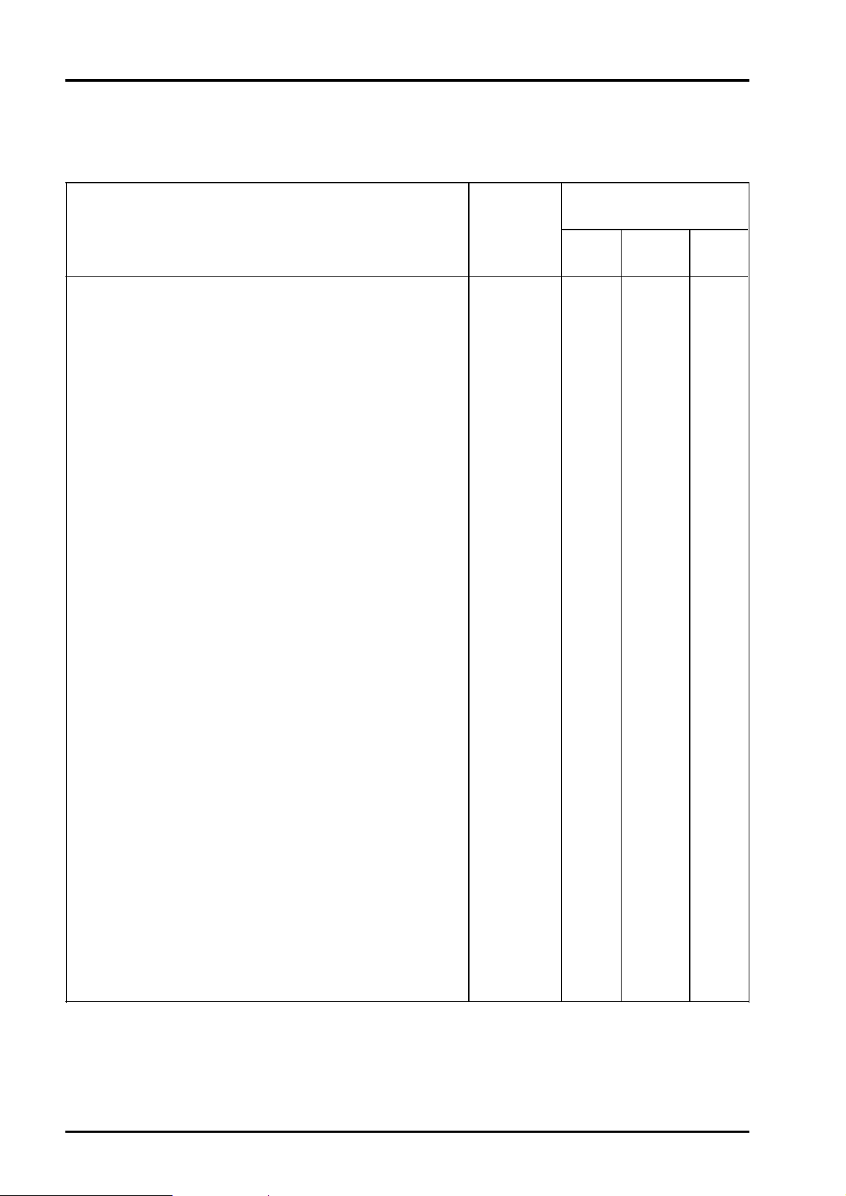
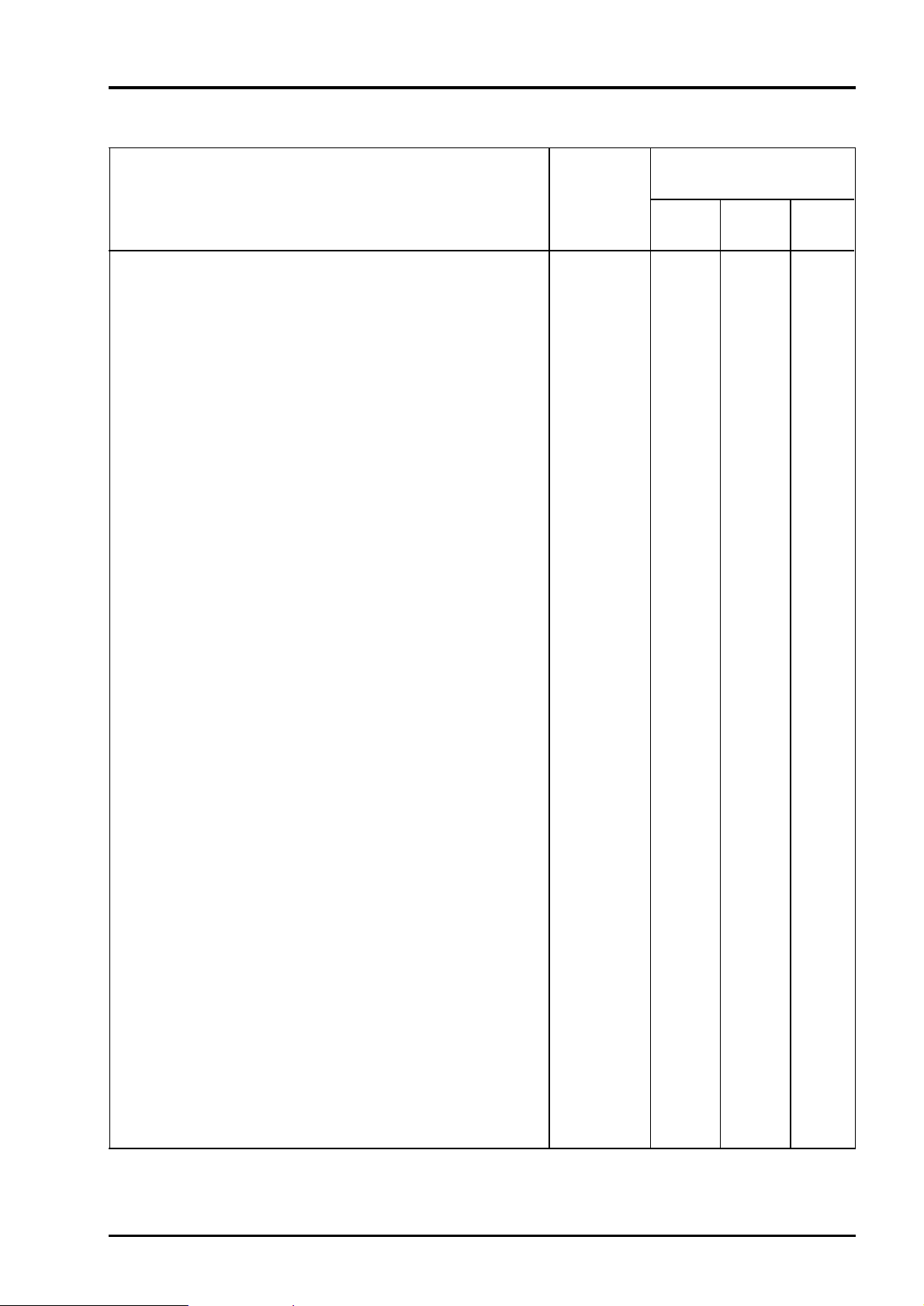
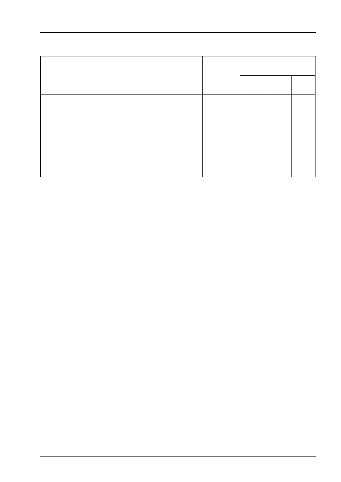
Recommended torque tensions
The torque tensions below apply to components lubricated lightly with clean engine oil before they are
fitted.
Torque
Description
Cylinder head assembly
Setscrews, cylinder head 1/2 UNF (see section 12)
Fasteners, rocker shaft brackets:
- Aluminium brackets M12 40 30 4,1
- Cast iron and sintered steel brackets M12 75 55 7,6
Cap nuts, rocker cover M12 20 15 2,1
Cap nuts, aluminium rocker cover (with shim washer) M12 30 22 3,0
Setscrews, inlet manifold to cylinder head M10 44 33 4,5
Nuts (plated), exhaust manifold to cylinder head M10 44 33 4,5
Nuts (non-plated), exhaust manifold to cylinder head M10 50 37 5,1
Setscrews, engine lift bracket M10 44 33 4,5
Piston and connecting rod assemblies
Nuts, connecting rods 1/2 UNF 125 92 12,7
Setscrews, connecting rods 1/2UNF 155 114 15,8
Thread
size
Nm lbf ft kgf m
Banjo bolts, piston cooling jets. 3/4 UNF 20 15 2,0
Crankshaft assembly
Setscrews, main bearings (4 cylinder engines) 5/8 UNF 250 185 26,0
Setscrews, main bearings (6 cylinder engines) 5/8 UNF 265 196 27,0
Setscrews, crankshaft pulley 7/16 UNF 115 85 11,8
Setscrews, viscous damper to crankshaft pulley M12 75 55 7,6
Cap screws, viscous damper to crankshaft pulley M8 35 26 3,6
Cap screws, rubber bonded damper to crankshaft pulley M8 35 26 3,6
Setscrews, rear oil seal housing to cylinder block M8 22 16 2,2
Torxscrew, rear oil seal housing to cylinder block M8 22 16 2,2
Cap screws, bridge piece to cylinder block M6 16 12 1,6
Cap screws, rear oil seal housing to bridge piece M8 18 13 1,9
Cap screws, rear oil seal housing to bridge piece M6 13 10 1,3
Torxscrew, rear oil seal housing to bridge piece M8 18 13 1,9
11B.02 Perkins Phaser/1000 Series, April 1995
Page 18
RECOMMENDED TORQUE TENSIONS 11B
Torque
Description
Setscrew, idler gear hub of balancer unit M12 93 68 9,5
Nut, drive gear of balance weight 1/2 UNF 82 60 8,4
Setscrews, rear cover of balancer frame M10 54 40 5,5
Setscrews, oil transfer plate (balancer unit) M10 30 22 3,1
Setscrews, oil pump to balancer frame M8 27 20 2,8
Setscrews, balancer to cylinder block M10 54 40 5,5
Timing case and drive assembly
Setscrews, timing case to cylinder block M8 22 16 2,2
Setscrews, timing case to cylinder block M10 44 33 4,5
Setscrews, hub of idler gear M10 44 33 4,5
Setscrew, camshaft gear M12 78 58 8,0
Setscrew, camshaft gear (for engines, with 45 mm long
setscrew)
Setscrews, timing case cover to timing case M8 22 16 2,2
Nuts, timing case cover to timing case M8 22 16 2,2
Thread
size
M12 100 74 10,0
Nm lbf ft kgf m
Cylinder block
Setscrews, fitted instead of piston cooling jets 3/8 UNF 27 20 2,8
Aspiration system
Nuts, turbocharger to manifold M10 44 33 4,5
Setscrew, breather cover M6 9 7 0,9
Fuel system
Nuts, high-pressure fuel pipes M12 22 16 2,2
Setscrews, atomiser M8 12 9 1,2
Setscrews, fuel lift pump M8 22 16 2,2
Nut for gear of fuel injection pump M14 80 59 8,2
Cap screw for gear of in-line fuel injection pump: AE, YE
engines
Nut for hub of in-line fuel injection pump: AE, YE engines M18 115 84 11,8
Nuts for adaptor plate of in-line fuel injection pump: AE, YE
engines
Nuts for flange of fuel injection pump M8 22 16 2,2
Locking screw for Bosch VE fuel injection pump shaft M10 27 20 2,8
M8 44 33 4,5
M10 44 33 4,5
Locking screw for DP 200 fuel injection pump shaft 10 A/F 10 7 1
Perkins Phaser/1000 Series, April 1995 11B.03
Page 19

11B RECOMMENDED TORQUE TENSIONS
Torque
Description
Lubrication system
Plug, lubricating oil sump 3/4 UNF 34 25 3,5
Setscrews, oil pump to front bearing cap M8 22 16 2,2
Setscrews, cover for oil pump M8 28 21 2,9
Fasteners, lubricating oil sump M8 22 16 2,2
Cooling system
Setscrews, fan drive housing to timing case M10 44 33 4,5
Setscrews, fan drive pulley to hub M8 22 16 2,2
Setscrews, fan drive pulley to hub M10 44 33 4,5
Setscrews, fan M8 22 16 2,2
Connector, oil cooler to oil filter head 3/4 UNF 58 42 5.8
Setscrews, coolant pump to timing case M8 22 16 2,2
Nut, auxiliary coolant pump pulley 1/2 UNF 70 52 7,1
Setscrew, intercooler flange to inlet manifold M6 7 5 0,7
Setscrew, intercooler body to inlet manifold M8 22 16 2,2
Thread
size
Nm lbf ft kgf m
Flywheel and housing
Setscrews, flywheel to crankshaft 1/2 UNF 105 77 10,7
Setscrews, cast iron flywheel housing to cylinder block M10 44 33 4,5
- Stamped 8.8 M12 75 55 7,6
- Stamped 10.9 M10 63 46 6,4
- Stamped 10.9 M12 115 85 11,7
Setscrews, aluminium flywheel housing to cylinder block M10 70 52 7,1
Setscrews, flywheel housing to cylinder block (paper joint) M10 70 52 7,1
Electrical equipment
Nut, alternator pulley:
- CAV AC5RA and AC5RS 5/8 UNF 55 40 5,6
- Lucas A127, and motorola, 22mm A/F M17 60 44 6,1
- Lucas A127, and motorola, 24mm A/F M17 80 59 8,2
- Bosch 55A M14 45 33 4,5
- Bosch 55A M16 50 37 5,1
- Butec 5524 5/8 UNF 78 58 8,0
Fuelled start aid to induction manifold 7/8 UNF 31 23 3,1
Port heater aid to induction manifold M22 60 44 6,1
11B.04 Perkins Phaser/1000 Series, April 1995
Page 20
RECOMMENDED TORQUE TENSIONS 11B
Torque
Description
Auxiliary equipment
Nut, compressor drive gear:
- 6,4 mm (0.25 in) thick 3/4 UNF 80 59 8,2
- 10 mm (0.4 in) thick 3/4 UNF 130 95 13,3
Nuts for gears of auxiliary drive assembly:
- 6,4 mm (0.25 in) thick 3/4 UNF 80 59 8,2
- 10 mm (0.4 in) thick 3/4 UNF 130 95 13,3
Nut for gears of auxiliary drive assembly M20 130 95 13,3
Thread
size
Nm lbf ft kgf m
Perkins Phaser/1000 Series, April 1995 11B.05
Page 21

CYLINDER HEAD ASSEMBLY 12
Cylinder head assembly12
General description. . . . . . . . . . . . . . . . . . . . . . . . . . . . . . . . . . . . . . . . . 12A.02
Rocker cover
12A-01To remove and to fit. . . . . . . . . . . . . . . . . . . . . . . . . . . . . . . . . 12A.03
Rocker assembly
12A-02To remove and to fit. . . . . . . . . . . . . . . . . . . . . . . . . . . . . . . . . 12A.05
12A-03To dismantle and to assemble. . . . . . . . . . . . . . . . . . . . . . . . . . 12A.06
12A-04To inspect and to correct. . . . . . . . . . . . . . . . . . . . . . . . . . . . . 12A.06
Valve tip clearances
12A-05To check and to adjust. . . . . . . . . . . . . . . . . . . . . . . . . . . . . . . 12A.07
Valve springs
12A-06To change the valve springs (with cylinder head fitted). . . . . . . . 12A.09
Cylinder head assembly
12A-07To remove and to fit. . . . . . . . . . . . . . . . . . . . . . . . . . . . . . . . . 12A.11
Valves and valve springs
12A-08To remove and to fit. . . . . . . . . . . . . . . . . . . . . . . . . . . . . . . . . 12A.16
12A-09To inspect and to correct. . . . . . . . . . . . . . . . . . . . . . . . . . . . . 12A.17
Valve guides
12A-10To inspect. . . . . . . . . . . . . . . . . . . . . . . . . . . . . . . . . . . . . . . . 12A.18
12A-11To remove and to fit. . . . . . . . . . . . . . . . . . . . . . . . . . . . . . . . . 12A.19
Cylinder head
12A-12To inspect and to correct. . . . . . . . . . . . . . . . . . . . . . . . . . . . . 12A.20
12A-13To correct a valve seat with a valve seat cutter. . . . . . . . . . . . . 12A.21
12A-14To fit valve seat inserts. . . . . . . . . . . . . . . . . . . . . . . . . . . . . . . 12A.22
Data and dimensions. . . . . . . . . . . . . . . . . . . . . . . . . . . . . . . . . . . . . . . 12A.23
Perkins Phaser/1000 Series, April 1995 12A.01
Page 22

12 CYLINDER HEAD ASSEMBLY
General description
In a diesel engine there is little carbon deposit and
for this reason the number of hours run is no
indication of when to overhaul a cylinder head
assembly. The factors which indicate when an
overhaul is necessary are how easily the engine
starts and its general performance.
The cylinder head assembly has two valves fitted
for each cylinder, each fitted with double or single
valve springs, according to the engine application.
The double springs have damper coils which are
fitted towards the top face of the cylinder head.
In most engines the face angle of the valves is 45°,
but some engines have inlet valves with a face
angle of 30°. The angle of the valve seats in the
cylinder head are either 46° or 31°.
The valves move in phosphated guides which can
be renewed. The exhaust valve guide has a
counterbore at the bottom and is a little longer than
the inlet valve guide.
Both valve stems are fitted with oil seals which fit
over the top of the valve guides.
Turbocharged engines and some naturally aspirated
engines have valve seat inserts fitted in the cylinder
head for both inlet and exhaust valves. Engines
which do not have valve seat inserts fitted as
standard, in production, can have them fitted in
service.
12A.02 Perkins Phaser/1000 Series, April 1995
Page 23
CYLINDER HEAD ASSEMBLY 12
aaa
aaa
aaa
aaa
aaa
aaa
Rocker cover
To remove and to fit12A-01
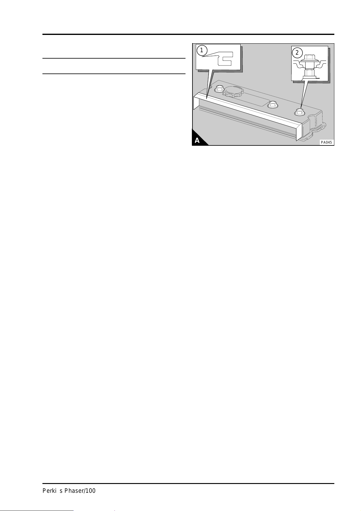
Engines are supplied with either an aluminium
rocker cover (A) or with rocker covers made of a
composite material (12A.04/A). The aluminium
cover on some engines, has a dust seal which is
fitted between the rocker cover and the induction
manifold. The dust seal of the composite rocker
cover is fitted permanently to the side of the rocker
cover with adhesive.
To remove
1 Disconnect the breather pipe.
2 Remove the cap nuts (A2) together with the steel
washers and the shim washers (12A-04/A) from the
top of the rocker cover.
3 Lift off the rocker cover and the joint. For
aluminium covers, remove the rocker cover dust
seal (A1).
Caution: When the rocker cover is fitted, the cap
nuts are tightened onto the nuts of the rocker
brackets. During removal of the cap nuts, it is
possible to loosen the nuts of the rocker brackets.
The nuts of the rocker brackets should be tightened
to the correct torque every time the cover is
removed.
1
2
PA045
Perkins Phaser/1000 Series, April 1995 12A.03
Page 24
12 CYLINDER HEAD ASSEMBLY
aaa
aaa
aaa
aaa
a
a
a
a
a
a
a
a
a
a
a
a
a
a
a
a
a
a
a
a
a
a
a
a
a
a
a
a
a
a
a
a
a
a
aaa
aaa
aaa
To fit
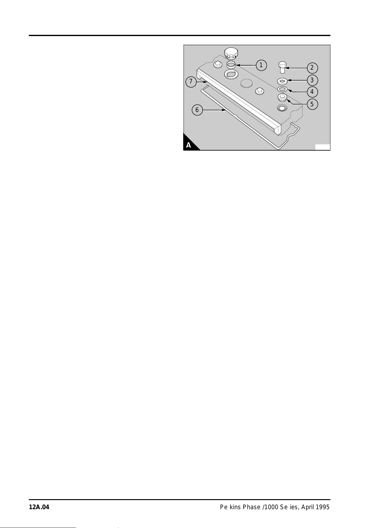
1 Check the seal of the oil filler cap (A1), the
sealing washers (A5), the steel washer (A3) and, if
fitted, the shim washer (A4) for the cap nuts (A2).
2 Check the condition of the rocker cover joint (A6)
and of the dust seal (A7). If necessary, the joint and
the seal can be removed and renewed.
3 Clean the joint face of the cylinder head and fit
the rocker cover together with the dust seal.
4 Fit the sealing washers, the steel washers, the
shims (if fitted) and the cap nuts.
Caution: Damage to the sealing washer can occur
if the cap nut is not tightened centrally through the
sealing washer and the rocker cover. If the sealing
washer is damaged it must be renewed.
5 Tighten the cap nuts to 20 Nm (15 lbf ft)
2,1 kgf m.
Notes:
• The latest engines have an extra shim washer
(A4) fitted between the cap nut sealing washer and
the steel washer for the cap nut. If shim washers
are fitted to aluminium rocker covers, tighten the
cap nuts to 30 Nm (22 lbf ft) 3,0 kgf m. If shim
washers are fitted to composite rocker covers,
tighten the cap nuts to 20 Nm (15 lbf ft) 2,1 kgf
m.
• Some earlier 1000 Series engines have a rocker
cover joint that has a ribbed bottom face. When this
joint is fitted, ensure that the flat face of the joint is
towards the rocker cover.
1
7
2
3
4
5
6
PA046
12A.04 Perkins Phaser/1000 Series, April 1995
Page 25
Rocker assembly
To remove and to fit12A-02
To remove
1Remove the rocker cover, operation 12A-01.
2 Release evenly and gradually the fasteners of
the rocker shaft brackets; begin with the end
brackets and move toward the centre. Remove the
fasteners and the washers and lift off the rocker
assembly.
Note: The washers between the fasteners and the
rocker brackets have been removed on the latest
engines and new flange faced nuts and setscrews
have been fitted.
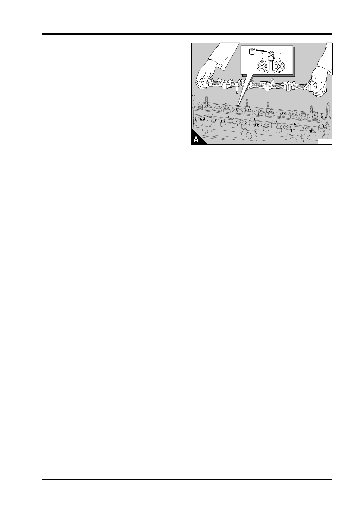
3 Remove the rubber oil seal (A) from the oil
supply connection or from the oil supply hole in the
cylinder head.
CYLINDER HEAD ASSEMBLY 12
PA047
To fit
1 Fit a new rubber oil seal in the oil supply hole in
the cylinder head.
2 Check that the push rods fit correctly in the
sockets of the tappets. Fit the rocker assembly;
ensure that the oil supply connection is fitted
correctly into the oil seal. Check that the ends of
the adjustment screws fit correctly in the sockets of
the push rods.
3 Fit the washers (if fitted) and fasteners of the
rocker shaft brackets and tighten the fasteners
evenly and gradually; begin with the inner fasteners
and work towards the end fasteners. Tighten the
fasteners evenly to the correct torque according to
the material of the rocker shaft brackets:
Aluminium 40 Nm (30 lbf ft ) 4,1 Kgf m.
Cast iron 75 Nm (55 lbf ft) 7,6 Kgf m.
Sintered steel 75 Nm (55 lbf ft) 7,6 Kgf m.
Perkins Phaser/1000 Series, April 1995 12A.05
Page 26
12 CYLINDER HEAD ASSEMBLY
aaa
aaa
aaa
aaa
1
PA048
Rocker assembly
To dismantle and to assemble12A-03
To dismantle
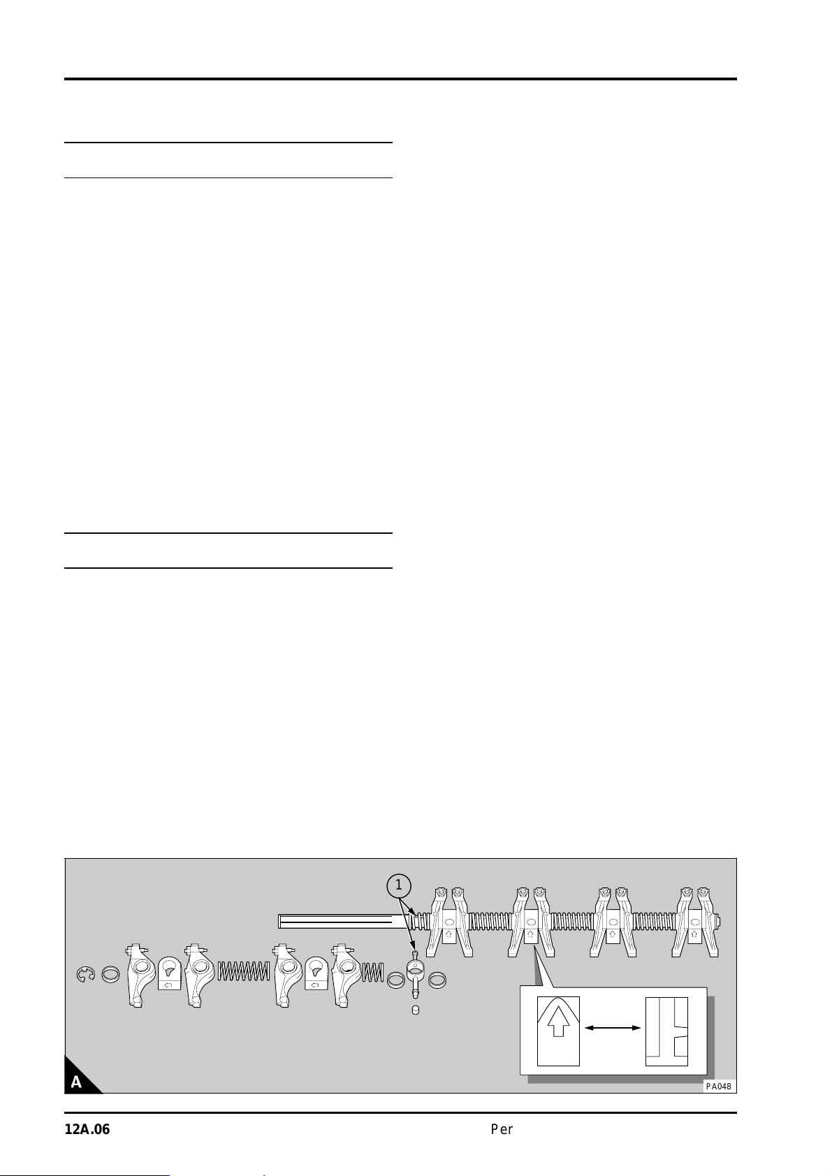
1 Remove the clips from both ends of the rocker
shaft. Ensure that the ends of the rocker shaft are
not damaged. Release the location screw (A1) for
the oil supply connection.
2 Dismantle the assembly and make a note of the
position of each component to ensure that they can
be assembled more easily.
To assemble
1 Ensure that the oil holes in the rocker shaft and
in the rocker levers are not restricted.
2 Lubricate the components with clean engine
lubricating oil before assembly. Assemble the
components in the correct order (A) and ensure
that the location screw (A1) for the oil supply
connection is fitted correctly in the rocker shaft. Fit
the clips to the ends of the rocker shaft.
3 Ream the bush in the rocker lever to give a
clearance on the rocker shaft of 0,03/0,09 mm
(0.001/0.004 in). Clean thoroughly the bush and
check that the oil hole is free from debris.
Note: The rocker levers used on some low rated
engines do not have bushes.
To inspect and to correct12A-04
To inspect
1 Clean and inspect all the components for wear
and any other damage. Check the clearance of the
rocker levers on the rocker shaft. If the clearance is
larger than 0,13 mm (0.005 in), renew the rocker
lever bush and/or the rocker shaft.
To correct
1 To renew the rocker lever bush, press out the
old bush with a suitable mandrel.
2 Align the lubrication hole of the new bush on the
same side as the rocker lever lubrication hole and
press the bush into position.
12A.06 Perkins Phaser/1000 Series, April 1995
Page 27
Valve tip clearances
To check and to adjust12A-05
Notes:
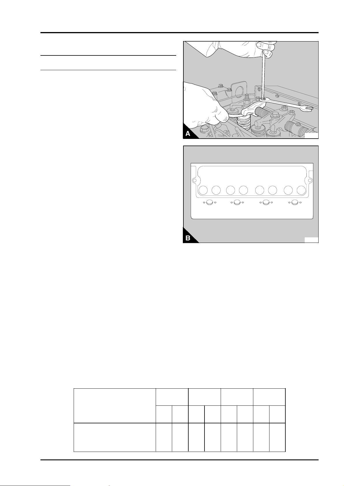
• The valve tip clearance is measured between the
top of the valve stem and the rocker lever (A). With
the engine hot or cold, the correct clearances are
0,20 mm (0.008 in) for the inlet valves and
0,45 mm (0.018 in) for the exhaust valves. The
valve positions are shown at (B).
• The sequence of valves from number 1 cylinder
is shown in the table below. Number 1 cylinder is at
the front of the engine.
Four cylinder engines
1 Rotate the crankshaft in the normal direction of
rotation until the inlet valve (B8) of number 4
cylinder has just opened and the exhaust valve (B7)
of the same cylinder has not closed completely.
Check the clearances of the valves (B1 and B2) of
number 1 cylinder and adjust them, if necessary.
2 Set the valves (B3 and B4) of number 2 cylinder
as indicated above for number 4 cylinder. Then
check / adjust the clearances of the valves (B5 and
B6) of number 3 cylinder.
3 Set the valves (B1 and B2) of number 1 cylinder.
Then check / adjust the clearances of the valves
(B7 and B8) of number 4 cylinder.
4 Set the valves (B5 and B6) of number 3 cylinder.
Then check / adjust the clearances of the valves
(B3 and B4) of number 2 cylinder.
CYLINDER HEAD ASSEMBLY 12
PA049
1 2 3 4 5 6 7 8
PA050
Cylinder
1
and
Valve number
12234356478
Valve
I = Inlet
IEEI IEEI
E = Exhaust
Perkins Phaser/1000 Series, April 1995 12A.07
Page 28
12 CYLINDER HEAD ASSEMBLY
a
a1a
a4a
a2a
a3a
a5a
a6a
a7a
a8a
a9aaa10aaa12aaa
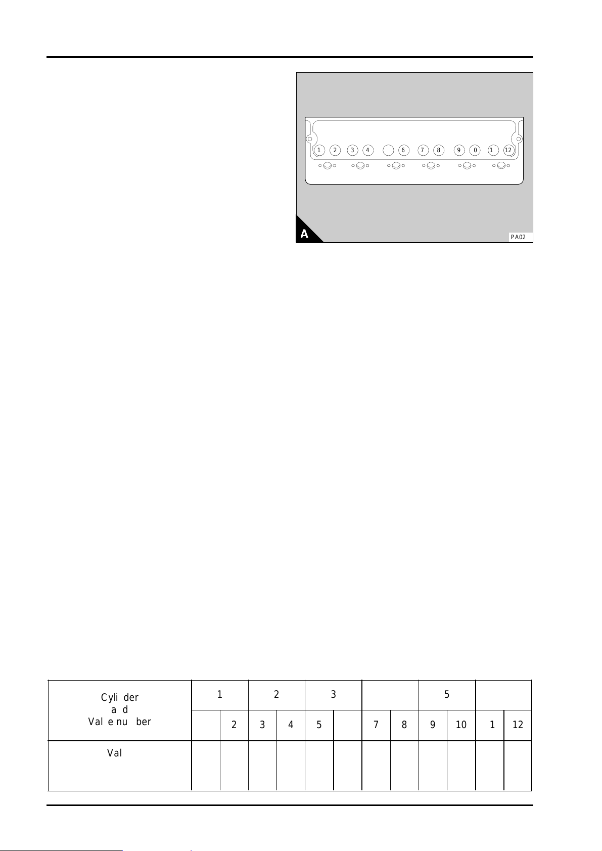
Six cylinder engines
1 Rotate the crankshaft in the normal direction of
rotation until the inlet valve (A12) of number 6
cylinder has just opened and the exhaust valve
(A11) of the same cylinder has not closed
completely. Check the clearances of the valves
(A1 and A2) of number 1 cylinder and adjust them,
if necessary.
2 Set the valves (A4 and A3) of number 2 cylinder
as indicated above for number 6 cylinder. Then
check / adjust the clearances of the valves
(A9 and A10) of number 5 cylinder.
3 Set the valves (A8 and A7) of number 4 cylinder.
Then check / adjust the clearances of the valves
(A5 and A6) of number 3 cylinder.
4 Set the valves (A1 and A2) of number 1 cylinder.
Then check / adjust the clearances of the valves
(A11 and A12) of number 6 cylinder.
5 Set the valves (A9 and A10) of number 5
cylinder. Then check / adjust the clearances of the
valves (A3 and A4) of number 2 cylinder.
6 Set the valves (A5 and A6) of number 3 cylinder.
Then check / adjust the clearances of the valves
(A7 and A8) of number 4 cylinder.
11
PA028
Cylinder
1
and
Valve number
122343564785910611 12
Valve
I = Inlet
IEEI IEEI IEEI
E = Exhaust
12A.08 Perkins Phaser/1000 Series, April 1995
Page 29
Valve springs
aaa
aaa
aaa
aaa
aaa
aaa
aaa
aaa
aaa
To change the valve springs (with cylinder head fitted)12A-06
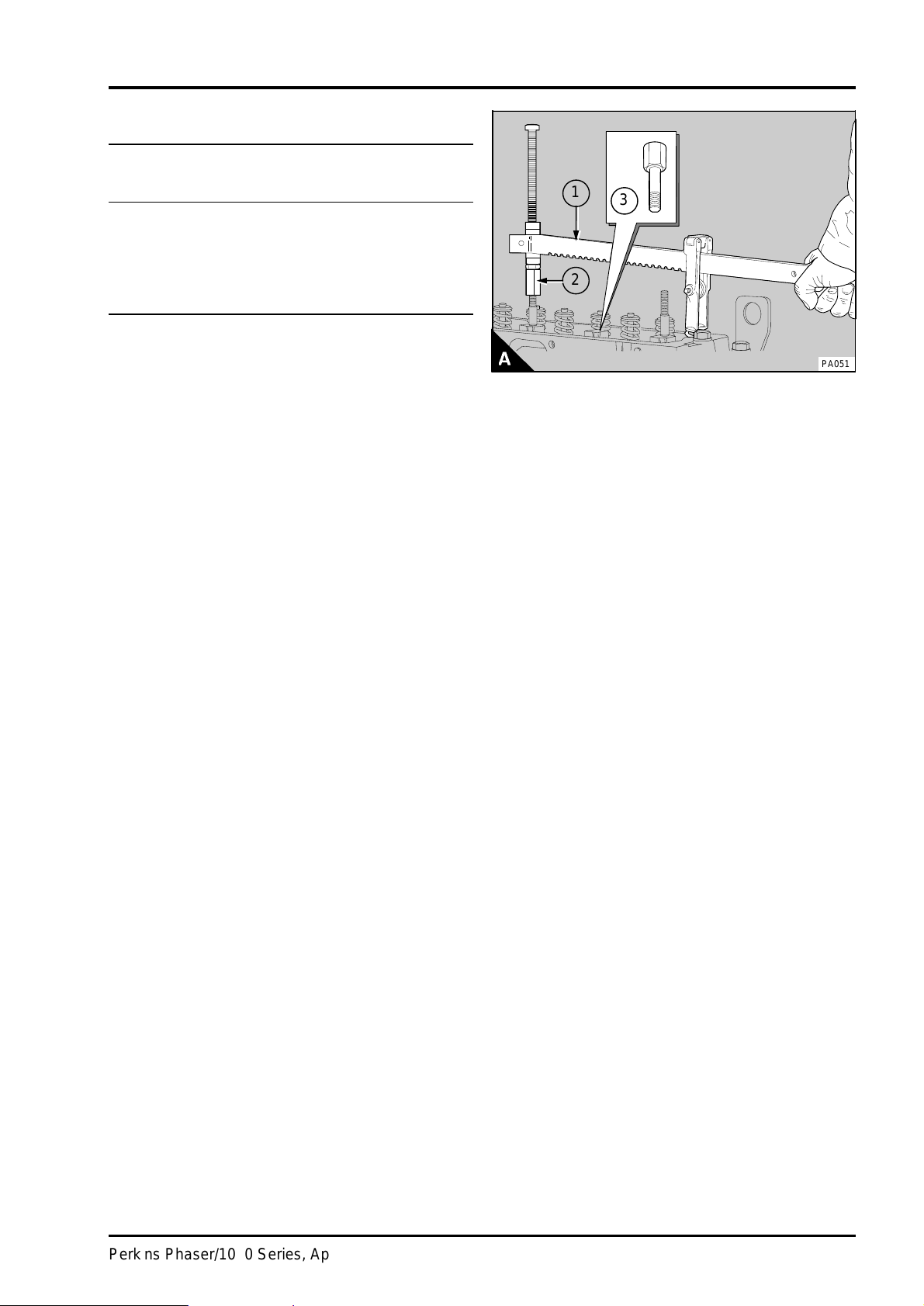
Special tools:
Valve spring compressor, PD.6118B
Stud adaptor used with PD.6118B, PD.6118-7
Setscrew adaptor used with PD.6118B, PD.6118-8
Note: Paragraphs 1 to 12 refer to a change of valve
springs for a single cylinder.
Warning! Wear eye protection during this operation.
1Remove the rocker cover, operation 12A-01.
2 Rotate the crankshaft in the normal direction of
rotation until the inlet valve of the relevant cylinder
has just opened and the exhaust valve has not fully
closed. In this position the piston will be at
approximately top dead centre (TDC).
3Remove the rocker assembly, operation 12A-02.
4 Fit the valve spring compressor (A1) and the
relevant adaptor (A2 or A3).
5 Compress the valve spring(s) and remove the
collets. Ensure that the valve springs are
compressed squarely or damage to the valve stem
can occur.
Caution: Do not rotate the crankshaft while the
valve springs are removed.
6 Release the valve spring compressor and
remove the valve spring caps and valve spring(s).
7 Put the new valve springs in position. If double
valve springs are fitted, ensure that the closed
damper coils are towards the cylinder head
(12A.16/A4).
CYLINDER HEAD ASSEMBLY 12
1
2
3
PA051
Perkins Phaser/1000 Series, April 1995 12A.09
Page 30
12 CYLINDER HEAD ASSEMBLY
8 Fit the valve spring caps.
Caution:
compressed squarely or damage can occur to the
valve stem.
9 Fit the valve spring compressor, compress the
valve springs and fit the collets. Remove the valve
spring compressor.
10Fit the rocker assembly, operation 12A-02.
11Check the valve tip clearances, operation
12A-05.
12Fit the rocker cover, operation 12A-01.
Note: If other or all of the valve springs are to be
changed, they can be changed two cylinders at a
time. The sets of cylinders are:
For 4 cylinder engines: 1 and 4, 2 and 3
For 6 cylinder engines: 1 and 6, 2 and 5, 3 and 4
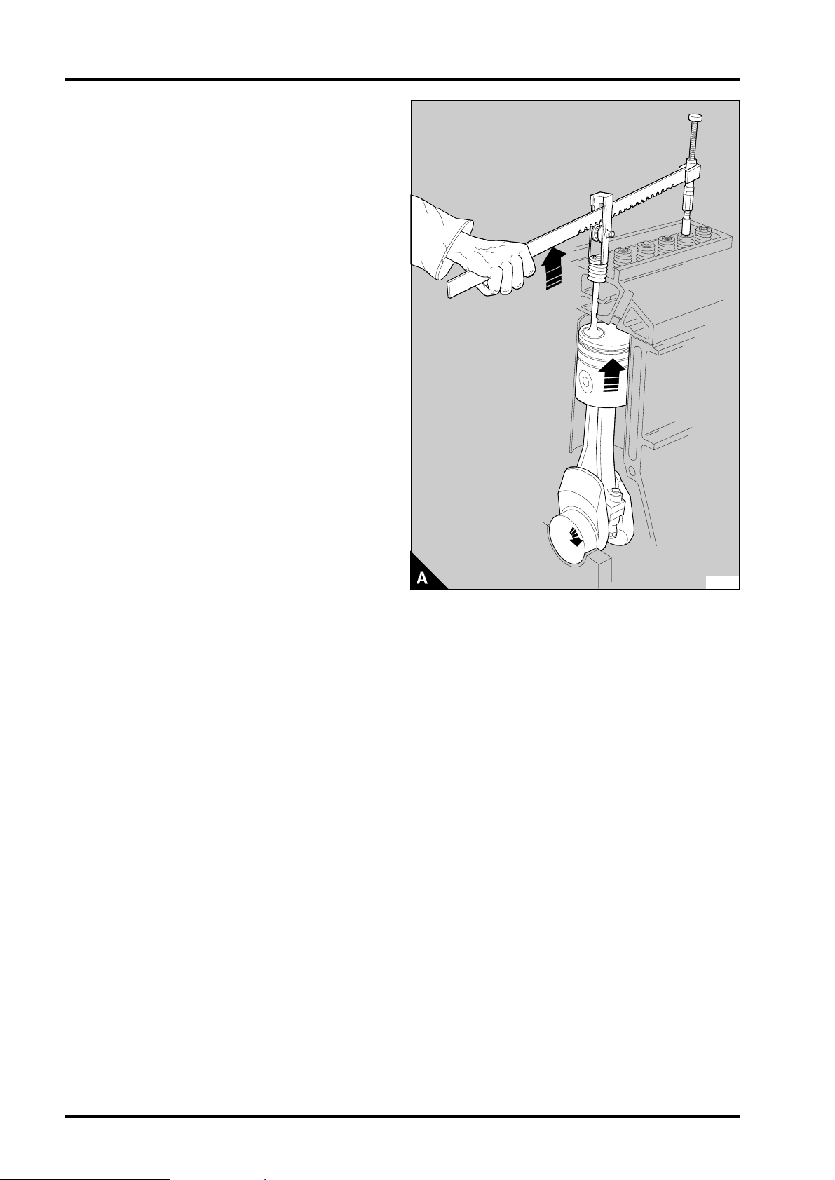
If the rocker assembly has been removed, piston
TDC can be found as follows:
1 Fit the valve spring compressor and compress
the valve springs to open the valve.
2 Rotate the crankshaft, by hand, in the normal
direction of rotation until the piston touches the
valve.
3 Continue to rotate the crankshaft, and at the
same time, release pressure on the valve spring
compressor until the piston is at TDC (A).
Ensure that the valve springs are
PA052
12A.10 Perkins Phaser/1000 Series, April 1995
Page 31

CYLINDER HEAD ASSEMBLY 12
Cylinder head assembly
To remove and to fit12A-07
To remove
1 Drain the cooling system.
2 Disconnect the battery terminals.
3 Remove the air filter/cleaner hose at the
induction manifold.
4 For engines fitted with turbochargers: Remove
the air filter/cleaner hose at the compressor inlet of
the turbocharger.
5 Remove the pipe which is fitted between the
fuelled starting aid in the induction manifold and the
fuel filter. Disconnect the electrical connection.
6 For engines fitted with a boost control device:
Remove the boost control pipe which is fitted
between the induction manifold and the top of the
fuel injection pump.
7 Remove the induction manifold.
8 For engines fitted with turbochargers: Disconnect
all connections to the turbocharger and remove the
turbocharger, operation 18A-01.
9 Remove the exhaust manifold.
10 Remove the low-pressure fuel pipes which are
fitted between the fuel injection pump and the fuel
filter.
Note: Where a Bosch fuel injection pump is fitted,
keep the fuel outlet banjo bolt with the fuel injection
pump.
Remove the fuel pipe fitted between the fuel lift
pump and the fuel filter. Remove the fuel filter
bracket together with the fuel filter.
11 Remove the high-pressure fuel pipes.
Caution: Where access to the fuel injection pump
outlet unions is possible, ensure that a separate
spanner is used to prevent movement of the fuel
injection pump outlets when the connections of the
high-pressure pipes are released. Fit suitable
covers to all open connections on the fuel injection
pump.
12 Remove the atomiser leak-off pipe.
13Remove the atomisers, operation 20A-02. Fit
suitable covers to the nozzles and the open
connections.
14 If a compressor is fitted: Remove the coolant
pipe which is fitted between the cylinder head and
the compressor. Then remove the coolant pipe
which is fitted between the by-pass connection and
the compressor.
15 Release the clip of the coolant by-pass hose at
the cylinder head. Release the setscrews and
remove the coolant by-pass connection and the
hose.
16 Disconnect the coolant temperature sender
unit.
17 For turbocharged and some naturally aspirated
four cylinder engines: Remove the oil cooler,
operation 21A-07A.
18Remove the rocker cover, operation 12A-01.
19Remove the rocker assembly, operation
12A-02.
20 Remove the push rods.
Perkins Phaser/1000 Series, April 1995 12A.11
Page 32
12 CYLINDER HEAD ASSEMBLY
a
a
a
a
a
a
a
a
a
a
a
a
a
a
a
a
a
a
a
a
a
a
a
a
aaa
aaa
a
a
a
a
a
a
a
a
a
a
a
a
a
a
a
a
a
a
a
a
aaa
aaa
a
a
a
a
aaa
a
a
a
a
a
a
a
a
a
a
a
a
a
a
a
a
a
aaa
aaa
aaa
aaa
aaa
aaa
aaa
aaa
aaa
aaa
a
a
a
aaa
aaa
a
a
a
a
a
a
a
a
a
a
a
a
a
a
a
a
aaa
aaa
aaa
aaa
aaa
aaa
aaa
aaa
a
a
a
a
a
a
a
a
a
a
a
a
a
a
a
a
a
a
a
a
a
a
a
a
a
a
a
a
aaa
aaa
aaa
a
a
a
a
a
a
aaa
aaa
M
aaa
aaa
S
a
a
a
a
S
a
a
a
a
S
aaa
aaa
S
a
a
a
a
S
aaa
aaa
S
aaa
aaa
S
a
a
a
a
S
a
a
a
a
S
aaa
aaa
S
aaa
aaa
S
a
a
a
a
S
a
a
a
a
M
aaa
aaa
M
a
a
a
a
M
a
a
a
a
M
aaa
aaa
M
aaa
aaa
M
a
a
a
a
M
a
a
M
aaa
aaa
M
a
a
M
M
aaa
M
aaa
aaa
M
aaa
M
aaa
aaa
M
aaa
M
a
a
a
a
M
a
aLa
a
L
PA055
aaa
aaa
30
aaa
aaa
31
aaa
aaa
32
aaa
aaa
20
aaa
aaa
21
aaa
aaa
22
aaa
aaa
11
aaa
aaa
12
a
a
a
a
6
a
a
a
a
5
aaa
aaa
17
aaa
a
a
a
16
aaa
aaa
27
aaa
aaa
26
aaa
aaa
10
a
a
a
a
7
a
a
a
a
4
aaa
aaa
15
aaa
aaa
25
aaa
aaa
18
a
a
a
a
8
aaa
aaa
2
aaa
aaa
13
aaa
aaa
23
aaa
aaa
28
aaa19a
a9a
a1a
a3aaa
14
aaa29aaa
24
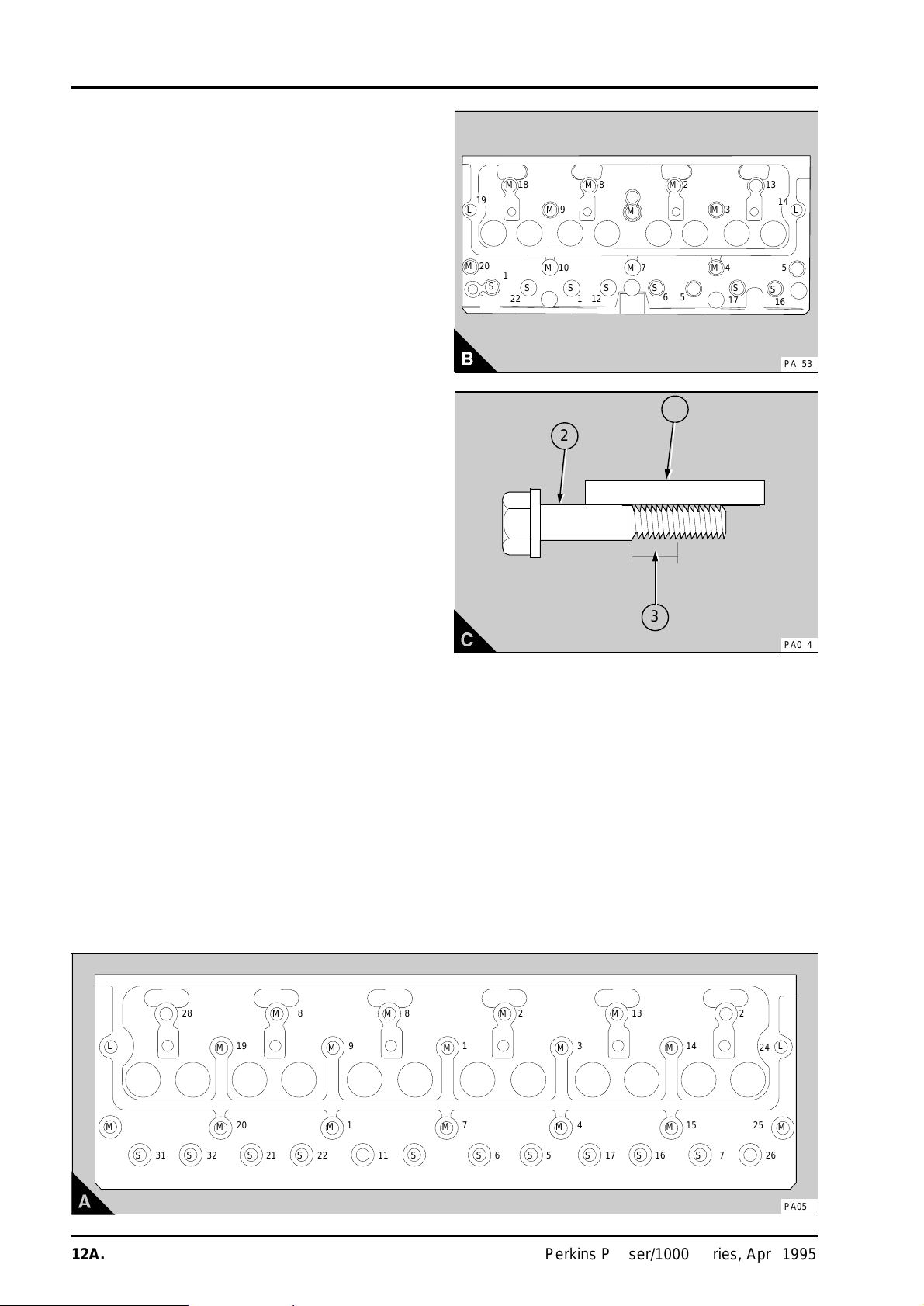
21 Release the cylinder head setscrews evenly
and gradually in the reverse sequence to that
shown in (A or B). Check the setscrews for
distortion with a straight edge (C1) held along the
setscrew (C2). If there is a visual reduction in the
diameter of the thread (C3) that has not been in
engagement with the cylinder block, the setscrew
must be discarded.
Caution: Do not use a lever to separate the
cylinder head from the cylinder block.
22 Remove the cylinder head and put it on a
surface that will not damage the face of the cylinder
head.
18
M
a
19
L
M
20
a
M
21
S
M
S
22
8
M
9
10
S
S
a
a
11
12
M
2
1
M
M
7
S
6
M
M
S
5
13
M
3
4
17
14
L
15
M
S
S
16
PA053
1
2
3
PA054
12A.12 Perkins Phaser/1000 Series, April 1995
a
a
Page 33
To fit
aaaaaaaaa
a
a
a
a
a
aaa
aaa
aaa
aaa
aaa
aaa
Special tools:
Angle gauge, to tighten cylinder head setscrews,
MS.1531
1 Clean the bottom face of the cylinder head and
top face of the cylinder block. Ensure that there is
no debris in the cylinder bores.
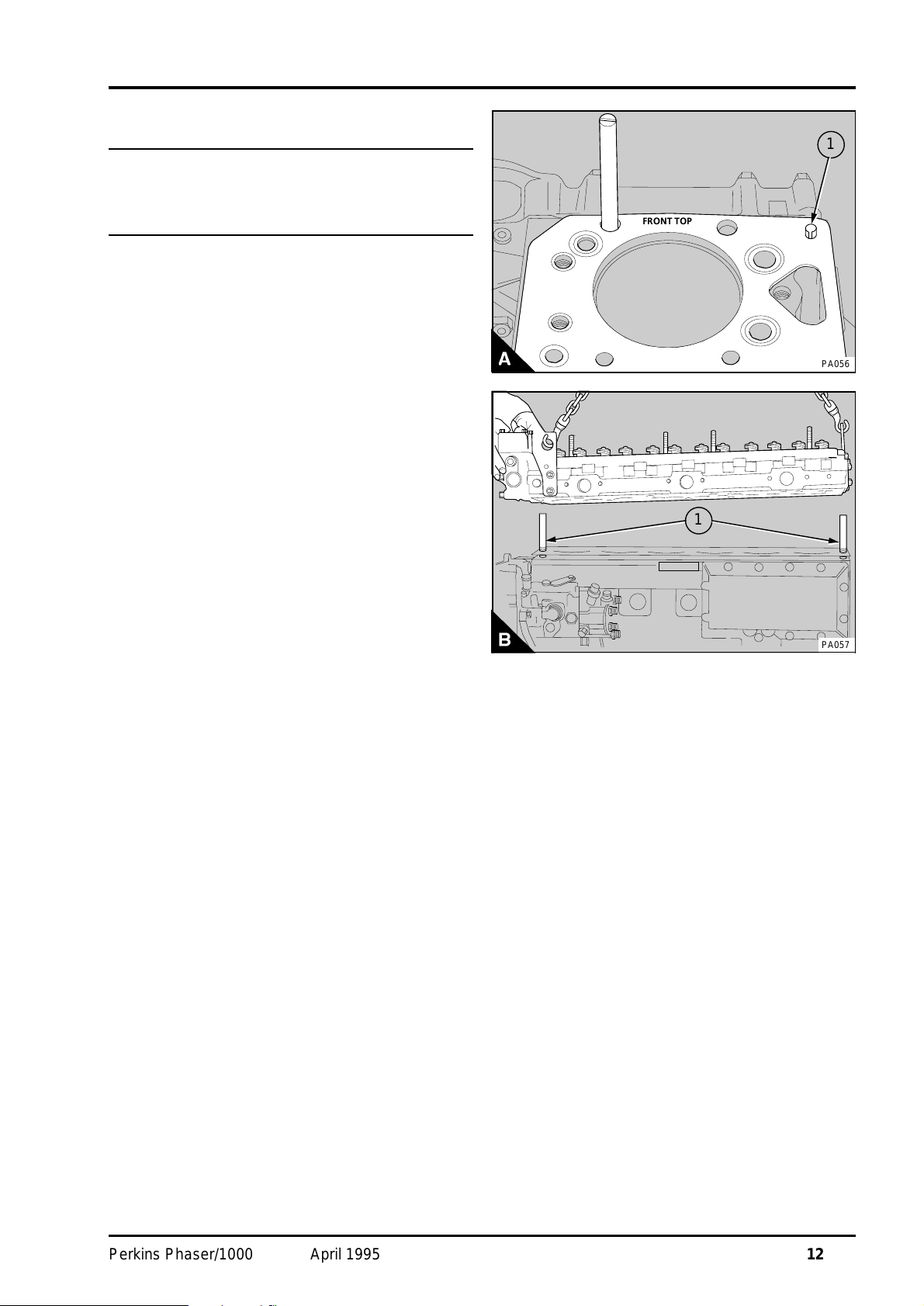
Note: Certain engines have two location pins (A1),
one at each end of the cylinder head, pressed into
the cylinder block to hold the cylinder head gasket
in the correct position before the cylinder head is
fitted.
Caution:
•
To prevent damage to the cylinder head gasket,
ensure that the location pins are
pressed
in the
cylinder block before the cylinder head is fitted.
•
The cylinder head gasket must be fitted without
jointing compound.
2 Put the cylinder head gasket in position; It is
stamped "FRONT TOP" for correct assembly (A).
3 To ensure the cylinder head is fitted into the
correct position, fit two suitable 1/2 UNF guide
studs (B1) in positions 15 and 20 (12A.12/B) or
positions 25 and 30 (12A.12/A). Put the cylinder
head in position.
4 Lightly lubricate the threads of the cylinder head
setscrews and the thrust faces of the setscrew
heads. Engage some of the setscrews in their
correct positions and remove the guide studs.
Engage the remainder of the setscrews in their
correct positions.
5 Gradually and evenly tighten the setscrews to
110 Nm (80 lbf ft) 11,1 kgf m in the sequence
shown in (12A.12/A or B).
6 Repeat paragraph 5 to ensure that all the
setscrews are tightened to the correct torque.
CYLINDER HEAD ASSEMBLY 12
1
aaaaaaa
aaaaaaa
a
a
PA056
1
PA057
FRONT TOP
Perkins Phaser/1000 Series, April 1995 12A.13
Page 34
12 CYLINDER HEAD ASSEMBLY
aaa
aaa
aaa
aaaaa
a
a
aaa
aaa
aaaaa
a
a
a
aaa
aaa
aaaaa
a
a
a
a
a
a
a
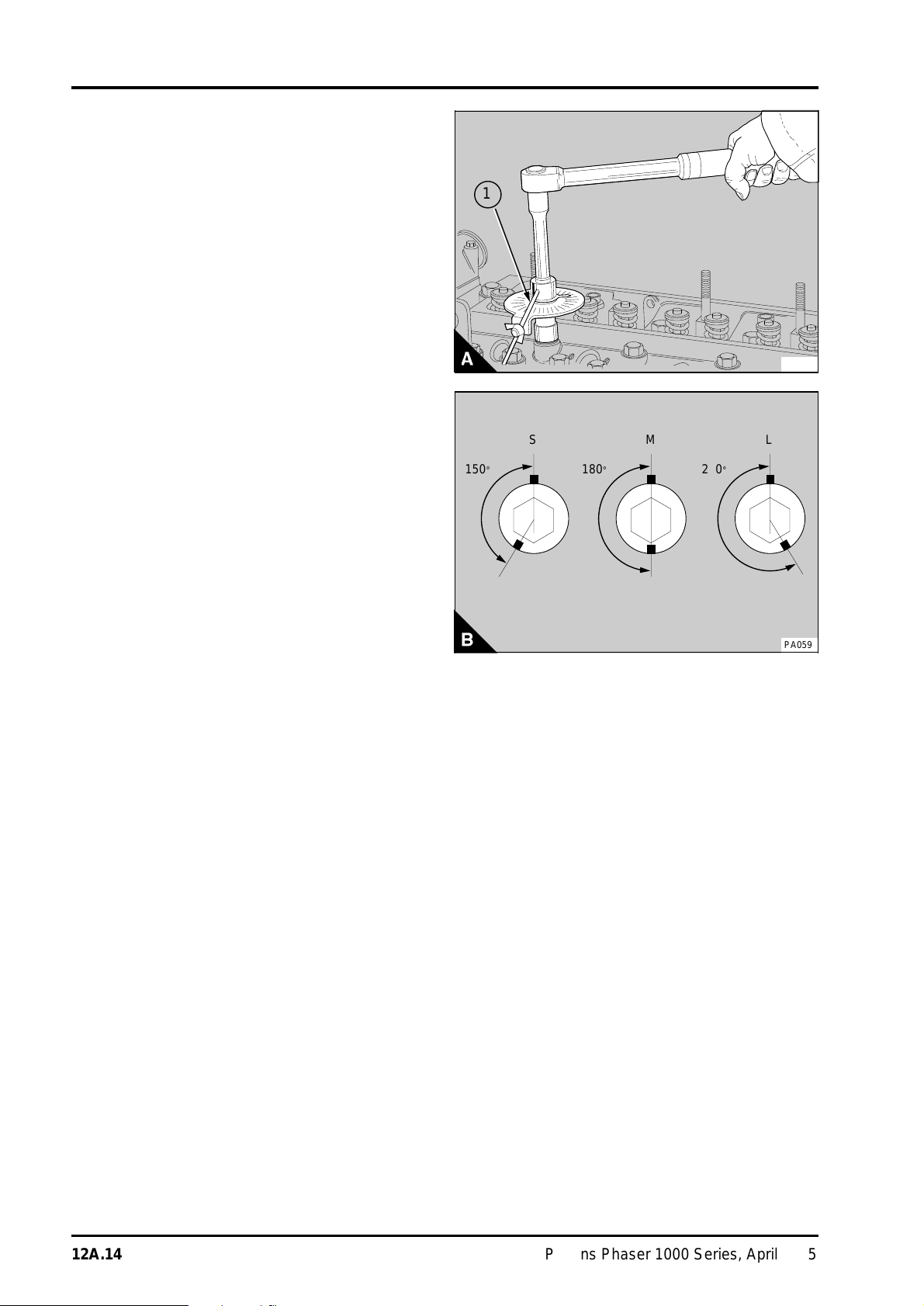
7 Tighten the setscrews, in the correct sequence,
a further part of a turn according to the length of
the setscrews, see (12A.12/A or B). Short
setscrews (S) must be turned a further 150°
(2.5 flats). Medium length setscrews (M) must be
turned a further 180° (3 flats). Long setscrews (L)
must be turned a further 210° (3.5 flats). A special
tool (A) can be used for this operation.
Fit the tool between the socket and the handle.
Position the stop (A1) against a suitable protrusion
on the cylinder head to prevent movement of the
degree dial in a clockwise direction. Rotate the
pointer to align with the relevant angle on the
degree dial for the length of setscrew. Tighten the
setscrew until the pointer on the tool is aligned with
the zero position on the degree dial.
If no tool is available, make a suitable mark on the
cylinder head in line with a corner of each setscrew
(B). Make another mark, at the correct angle
(counter-clockwise), on the edge of the flange of
each fastener according to the length of the
setscrew. Tighten each setscrew in the correct
sequence until the marks on the flange are next to,
and in line with, the marks on the cylinder head.
8 Put the push rods in position. Ensure that the
end of each push rod fits correctly in the tappet
socket.
9Fit the rocker assembly, operation 12A-01.
10Set the valve tip clearances, operation 12A-05.
11Fit the atomisers, operation 20A-02.
12 Fit the high-pressure fuel pipes; tighten the
connection nuts to 22 Nm (16 lbf ft) 2,2 kgf m.
Caution: Where access to the fuel injection pump
outlet unions is possible, ensure that a separate
spanner is used to prevent movement of the fuel
injection pump outlets when the connections of the
high pressure pipes are tightened.
13 Fit the fuel filter and the bracket. Fit the lowpressure fuel pipes between the fuel injection pump
and the fuel filter.
14 Fit the coolant by-pass connection; tighten the
setscrews and hose clip.
15 If a compressor is fitted: Fit the coolant pipe
between the cylinder head and the compressor.
Then fit the pipe between the coolant by-pass and
compressor.
16 For turbocharged and some naturally aspirated
four cylinder engines: Fit the oil cooler, operation
21A-07A.
150°
aaa
1
PA058
S
180°
aaa
M
a
210°
aaa
L
a
PA059
12A.14 Perkins Phaser/1000 Series, April 1995
Page 35
17 Fit the exhaust manifold. The manifold joints are
fitted without jointing compound.
18 For engines fitted with turbochargers: Fit the
turbocharger, operation 18A-01.
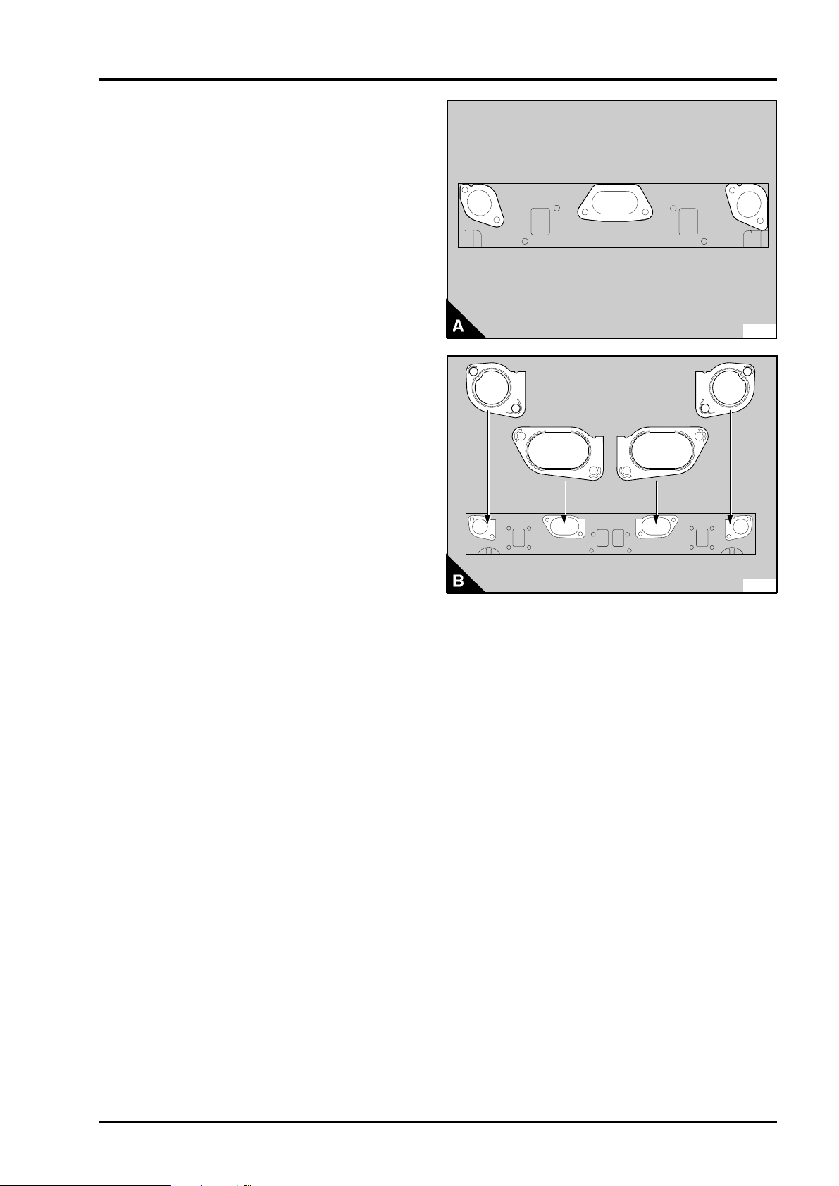
19 For four cylinder engines: Fit the induction
manifold. Ensure that the manifold joints for the
front and rear positions are fitted with the notch at
the top left when the manifold is fitted to the
cylinder head (A). The manifold joint for the centre
position can be fitted either way. Fit the joints
without jointing compound.
For six cylinder engines: Fit the induction manifold.
Ensure that the joints are fitted with the notch at the
top and the straight edge towards the centre (B). Fit
the joints without jointing compound. Some of the
latest six cylinder engines are fitted with a one
piece induction manifold joint.
20 Fit the fuel pipe between the fuel filter and the
fuel lift pump.
21 Fit the fuel pipe between the fuel filter and the
fuelled starting aid in the induction manifold.
Connect the electrical connection to the cold start
device.
22 For engines fitted with boost control devices: Fit
the boost control pipe between the induction
manifold and the top of the fuel injection pump.
23 Fit the electrical connection to the coolant
temperature sender unit.
24 Connect the coolant outlet and the hoses for
the cab heater. Tighten the clips.
25 Fill the cooling system.
26 Connect the air filter/cleaner.
27 Connect the battery.
28Eliminate air from the fuel system, see section
20.
29 Start the engine and run it at low speed. Check
that oil flows from the holes in the rocker levers. If
the oil flow is correct, fit the rocker cover, operation
12A-01.
Note: It is not necessary to tighten the cylinder
head setscrews again with the engine hot or after a
limited period in service.
CYLINDER HEAD ASSEMBLY 12
PA060
PA061
Perkins Phaser/1000 Series, April 1995 12A.15
Page 36
12 CYLINDER HEAD ASSEMBLY
aaa
aaa
aaa
aaa
aaa
aaa
aaa
aaa
aaa
aaa
aaa
aaa
aaa
aaa
aaa
aaa
aaa
aaa
aaa
aaa
aaa
aaa
aaa
aaa
aaa
Valves and valve springs To remove and to fit12A-08
Special tools:
Valve spring compressor, PD.6118B
Stud adaptor, PD.6118-7
Setscrew adaptor, PD.6118-8
To remove
1Remove the cylinder head, operation 12A-07.
2 Clean the bottom face of the cylinder head and
check the depth of the heads of the valves below
the face of the cylinder head, see operation 12A-09.
3 Make a suitable mark on the heads of the valves
to ensure that the valves can be fitted in their
original positions, if they are to be used again.
Warning! Wear eye protection during this operation.
Caution: Ensure that the valve springs are
compressed squarely or the valve stem can be
damaged.
4 Use the valve spring compressor and the
relevant adaptor to compress the valve spring(s)
and remove the collets.
5 Release the valve spring compressor and
remove the valve spring cap, valve spring(s), valve
stem seal and the valve seat washer.
6 Repeat items 4 and 5 for the other valves.
1
2
3
4
5
6
7
8
PA062
To fit
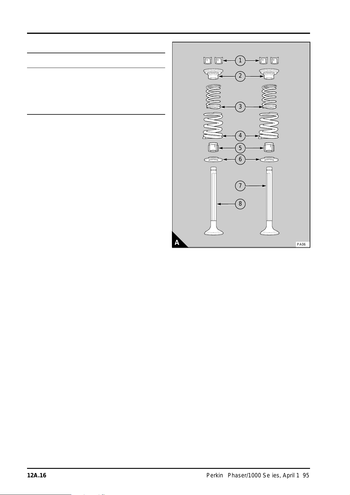
Note: The components of the valve assembly are
shown in A. Certain engines are fitted with single
valve springs.
1 Lubricate the valve stems (A7 and A8) with clean
engine oil and fit the valves in their respective
guides.
2 Fit the spring seat washers (A6). Fit new valve
stem seals (A5) on the valve guides. If double valve
springs are used, fit the inner and outer valve
springs (A3 and A4) on the spring seat washers
with their damper coils toward the cylinder head. If
single valve springs are used, the spring does not
have a damper coil and it can be fitted with either
end to the cylinder head. Fit the valve spring caps
(A2).
Warning! Wear eye protection during this operation.
Caution: Ensure that the valve springs are
compressed squarely or damage can occur to the
valve stem
.
3 Use the valve spring compressor and the
relevant adaptor to compress the valve spring(s)
and fit the collets (A1).
12A.16 Perkins Phaser/1000 Series, April 1995
Page 37
To inspect and to correct12A-09
a
a
a
a
a
a
Special tool:
Gauge, valve depth, PD.41D
Dial gauge for use with PD.41D, PD.208
1 Check the depth of the valves below the face of
the cylinder head before the valve springs are
removed.
2 Ensure that the heads of the valves and the
bottom face of the cylinder head are clean.
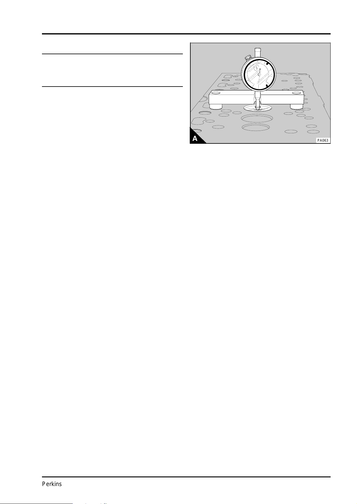
3 Put the valve depth gauge on the face of the
cylinder head and zero the dial gauge.
4 Carefully put the valve depth gauge in position
over the head of each valve (A) and make a note of
the measurement. The maximum depth, in service,
is given in the data and dimensions.
5 If a valve is below the depth limit, check the
valve depth with a new valve in position. If the valve
depth is still below the limit and a valve seat insert
is fitted, the insert must be renewed.
6 Where a valve seat insert is not fitted, the bottom
face of the cylinder head can be machined to
reduce the valve depth, or an insert can be fitted,
operation 12A-14.
Caution: If the bottom face of the cylinder head is
to be machined, ensure that the thickness, of the
cylinder head will not be less than 102,48 mm
(4.035 in) after the cylinder head has been
machined.
7 Check the valves for cracks. Check the stems of
the valves for wear and for correct fit in their valve
guides.
8 Check that the seat faces of the valves are not
badly burnt or damaged. Seat faces of valves which
are damaged can be ground on a special machine.
Valves which have only a little damage can be
lapped to their valve seats. When new valves are
fitted, the valve depths must be checked, see
paragraph 1.
9 Check that the load on the valve springs is
correct at their fitted length, see the data and
dimensions. Fit new valve springs at every
complete engine overhaul.
CYLINDER HEAD ASSEMBLY 12
PA063
Perkins Phaser/1000 Series, April 1995 12A.17
Page 38
12 CYLINDER HEAD ASSEMBLY
aaa
aaa
aaa
aaa
aaa
aaa
aaa
aaa
aaa
aaa
aaa
aaa
aaa
a
a
a
a
a
a
Valve guides
To inspect12A-10
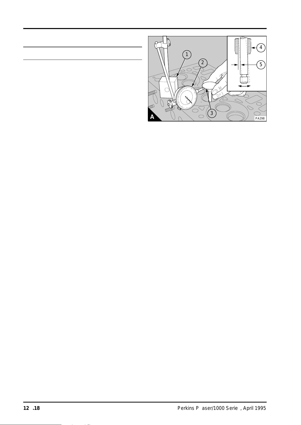
To check the valve guides for wear: The maximum
clearance (A5), between the valve stem and the
bore of the guide is 0,13 mm (0.005 in) for inlet
valves and 0,15 mm (0.006 in) for exhaust valves. If
the clearance, with a new valve fitted, is more than
the limit, then a new valve guide (A4) must be
fitted.
It is recommended that the procedure given below
is used to check the valve guide clearance:
1 Put a new valve in the valve guide.
2 Put a dial test indicator with a magnetic base
(A1) onto the face of the cylinder head
3 With the valve lifted 15,0 mm (0.6 in) and the
gauge (A2) in contact with the edge of the valve
head (A3), move the valve radially away from the
gauge. With the valve held in this position, set the
gauge zero.
4 Move the valve radially across the axis of the
cylinder head towards the gauge. Make a note of
the reading on the gauge. If the reading is equal to
or greater than the data given below, a new valve
guide (A4) must be fitted.
Maximum permissible clearance with a valve lift of
15,0 mm (0.6 in) :
• Inlet guide 0,24 mm (0.009 in)
• Exhaust guide 0,32 mm (0.013)
4
1
2
5
3
PA298
12A.18 Perkins Phaser/1000 Series, April 1995
Page 39
CYLINDER HEAD ASSEMBLY 12
aaa
aaa
aaa
aaa
aaa
aaa
aaa
aaa
aaa
aaa
aaa
aaa
aaa
aaa
aaa
aaa
a
a
a
a
a
a
a
a
a
a
a
a
a
a
a
a
a
a
a
a
a
a
a
a
a
a
a
a
a
a
a
a
a
a
a
a
a
a
a
a
a
a
a
a
a
a
a
a
a
a
aaa
aaa
aaa
aaa
aaa
aaa
To remove and to fit12A-11
Special tools:
Remover/replacer for valve guides (main tool),
PD.1D
Adaptor used with PD.1D, PD.1D-1A
Adaptor used with PD.1D and PD.1D-1A, PD.1C-6
To remove
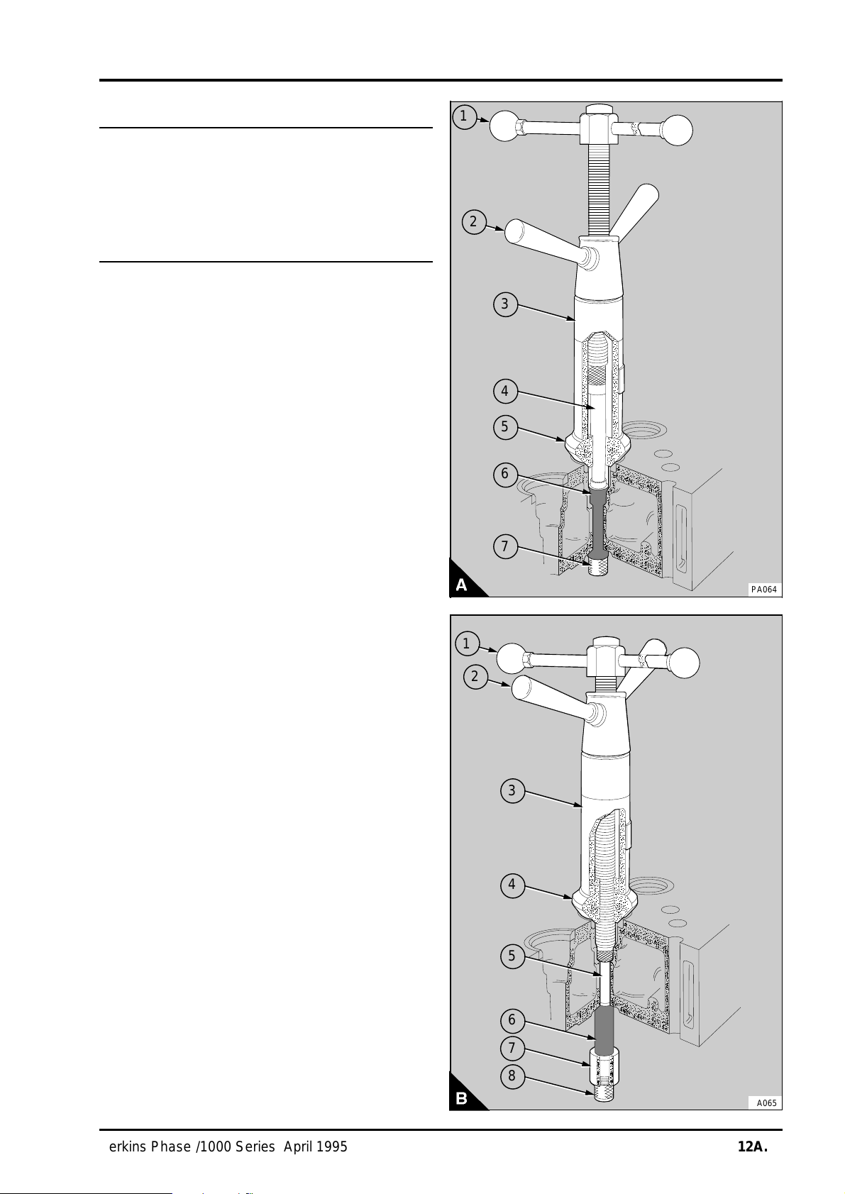
1 Fit the adaptor (A4), PD.1D-1A, into the
remover/replacer tool (A3), PD.1D.
2 With the adaptor fitted to the tool, put the spacer
(A5) in position on the tool. Pass the adaptor
through the valve guide and put the spacer and tool
in position on the valve seat.
3 Fit the attachment (A7) to secure the adaptor to
the valve guide.
4 Hold the top handle (A1) and turn the bottom
handle (A2) clockwise to pull the valve guide out of
the cylinder head.
1
2
3
4
5
6
To fit
1 Clean the parent bore in the cylinder head for the
valve guide.
2 Lubricate the outer surface of the new valve
guide (B6) with clean engine lubricating oil.
3 Fit the adaptor (B5), PD.1D-1A, into the
remover/replacer tool (B3), PD.1D.
4 With the adaptor fitted to the tool, put the spacer
(B4) in position on the tool. Pass the adaptor
through the cylinder head and put the spacer and
tool assembly in position on the valve seat.
5 Put the valve guide in position on the adaptor
and fit the distance piece (B7), PD.1C-6. Fit the
attachment (B8) to secure the valve guide to the
adaptor.
6 Hold the top handle (B1) and turn the bottom
handle (B2) clockwise to pull the valve guide until
the distance piece contacts the cylinder head.
7 When the valve guide is fitted correctly, the top
of the valve guide will have a protrusion of
15,10 mm (0.594 in) above the valve spring seat.
7
PA064
1
2
3
4
5
6
7
8
PA065
Perkins Phaser/1000 Series, April 1995 12A.19
Page 40

12 CYLINDER HEAD ASSEMBLY
Cylinder head To inspect and to correct12A-12
1Remove the cylinder head assembly, operation
12A-07.
2 Remove the thermostat housing.
3 Inspect the cylinder head for signs of gas or
coolant leakage.
4 Remove the valve springs and the valves,
operation 12A-08.
5 Clean the face of the cylinder head and the
passages for coolant and for lubricating oil. The
water jacket can be cleaned with a special solvent
which must be used in accordance with the
manufacturer's instructions.
6 Test the cylinder head for leaks at the pressure
given in the data and dimensions.
7 When the cylinder head is thoroughly clean,
check it for cracks. Inspect carefully the areas
around the valve seats and around the holes for the
atomiser nozzles.
8 The bottom face of the cylinder head can be
machined if: there is distortion, see paragraph 9;
there are deep scratches; or, for engines without
valve seat inserts, the valve depths are below the
service limit.
9 Use a straight edge and feeler gauges to check
the cylinder head for distortion across and along its
bottom face, see the data and dimensions. If the
distortion is more than the limit given in the data
and dimensions, the bottom face can be machined.
Caution: Remove only the minimum material and
ensure that the thickness of the cylinder head will
not be less than 102,48 mm (4.035 in) after the
cylinder head has been machined.
Notes:
• On AE and YE engines the protrusion of the
atomiser nozzle below the bottom face of the
cylinder head must not be more than 4,82 mm
(0.190 in).
• The nozzle protrusion must be measured with
the nozzle seat washer fitted.
Caution: After the cylinder head has been
machined the valve seats must be corrected to give
the correct valve head depth.Work to the minimum
limit to allow for later wear.
10 Check the valve seats for wear and for damage.
11 Before any work is done on the valve seats,
new valve guides must be fitted, operation 12A-11.
12 Where there is little damage, the valve and
valve seat can be lapped. When the valve seats are
lapped keep the seat as narrow as possible and
ensure that all the compound used to lap the valve
and the seat is removed.
13 More badly damaged valve seats can be
corrected by use of the cutter tool, operation
12A-13, or new inserts can be fitted, operation
12A-14.
12A.20 Perkins Phaser/1000 Series, April 1995
Page 41
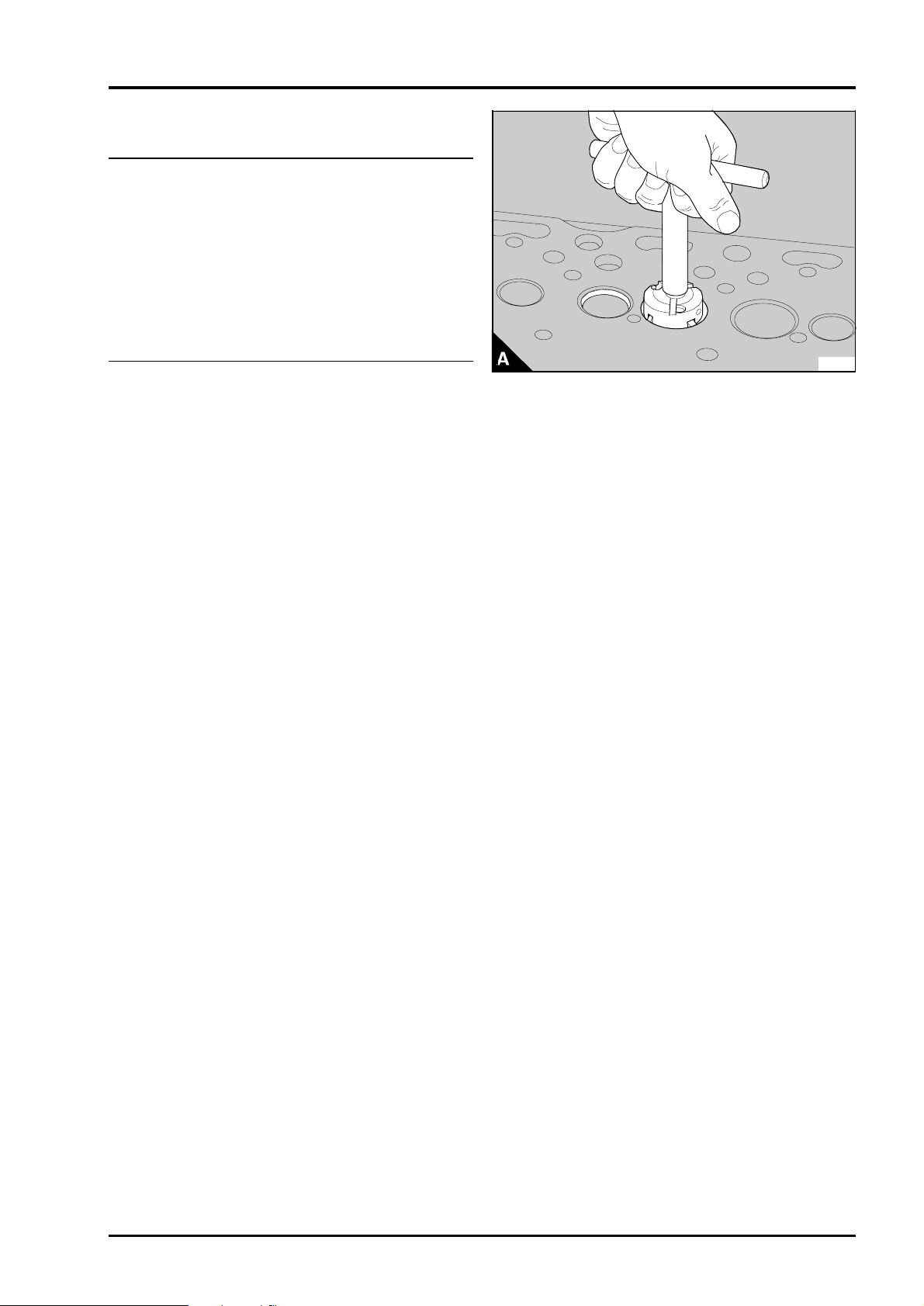
To correct a valve seat with a valve seat cutter12A-13
Special tools:
Cutter for 46° inlet valve seats, MS.281*
Cutter for 31° inlet valve seats, MS.642
Cutter for exhaust valve seats, MS.275*
Pilot for use with valve seat cutters, MS.150-9.5*
Handle set for use with valve seat cutters, MS.67B*
*Included in set of adjustable cutters for valve seats,
MS.73
1 Before any work is done on the valve seats, new
valve guides must be fitted, operation 12A-11.
2 Fit the pilot in the valve guide and tighten the
pilot.
3 Select the relevant cutter. Set the blades of the
cutters to the diameter of the valve seat to be cut.
Fit the cutter on the pilot and fit the handle (A).
Ensure that the cutter is not allowed to fall on to the
seat as this can damage the blades.
4 Carefully turn the cutter in a clockwise direction.
Remove only the minimum material to ensure a
good seat. Keep the seat as narrow as possible.
5 When the seat is cut, remove the cutter and the
pilot. Remove any debris from the area of the valve
seat and the port.
6 Fit the valve and lightly lap the valve and the
seat.
7 Check that the valve depth is within limits, see
data and dimensions.
Note: If a valve seat has become too damaged or
too worn to correct, a valve seat insert can be
fitted, operation 12A-14. Turbocharged engines and
some naturally aspirated engines have valve seat
inserts fitted as standard and these inserts can be
renewed.
CYLINDER HEAD ASSEMBLY 12
PA066
Perkins Phaser/1000 Series, April 1995 12A.21
Page 42

12 CYLINDER HEAD ASSEMBLY
To fit valve seat inserts12A-14
1 Remove the valve guide and clean the bore into
which the guide is to be fitted.
2Fit new valve guides, operation 12A-11.
3 With the bore of the new valve guide used as a
pilot, machine the recess in the cylinder head to the
dimensions shown in data and dimensions at the
end of this section, or machine out the old insert.
Remove all debris and clean the insert recess.
4 If the bottom face of the cylinder head has been
machined, the insert will have to be surface ground
on the back face to ensure that there is no
protrusion of the insert above the bottom face of
the cylinder head. After the back of the insert has
been ground, ensure that the outer edge of the
back face has a 0,9/1,3 mm (0.035/0.051 in)
chamfer at 30° to the vertical.
5 With the bore of the valve guide used as a pilot,
and with the rear face of the insert towards the
cylinder head, press in the insert with the valve seat
insert tool, see data and dimensions. Do not use a
hammer on the insert and do not use lubrication.
Use a hydraulic press or a hand press in one
continuous movement. Ensure that the bottom of
the insert is in contact with the bottom of the
recess.
6 Cut the valve seat at an included angle of 88°
for 46° valve seats or 118° for 31° valve seats,
operation 12A-13, and lap the valve on to the valve
seat. Ensure that the depth of the valve head below
the face of the cylinder head is within the
production limits, see data and dimensions. Work
as near as possible to the minimum figure to allow
for future wear on the valve seat.
12A.22 Perkins Phaser/1000 Series, April 1995
Page 43

CYLINDER HEAD ASSEMBLY 12
Data and dimensions
Note: This information is given as a guide for personnel engaged on engine overhauls. The dimensions
which are shown are those which are mainly used in the factory. The information applies to all engines,
unless an engine type code is shown.
Cylinder head
Angle of valve seat:
- Exhaust . . . . . . . . . . . . . . . . . . . . . . . . . . . . . . . . . . . . . . . . . . . . . . . . . . 46° (88° included angle)
- Inlet . . . . . . . . . . . . . . . . . . . . . . . . . . . . . . 46° (88° included angle) or 31° (118° included angle)
Diameter of parent bore for valve guide . . . . . . . . . . . . . . . . . . . . 15,87/15,89 mm (0.6247/0.6257 in)
Leak test pressure . . . . . . . . . . . . . . . . . . . . . . . . . . . . . . . . . . . . . 200 kPa (29 lbf/in
Head thickness . . . . . . . . . . . . . . . . . . . . . . . . . . . . . . . . . . . . . 102,79/103,59 mm (4.047/4.078 in)
Minimum permissible thickness after head face has been machined . . . . . . . . . . 102,48 mm (4.035 in)
- AE, YE engines. . . . . . . . . . . . . . . . . . . . . . . . . . . . . . . . . . . . . . . . . . . . . .See operation 12A-12
Inlet valves
Diameter of valve stem . . . . . . . . . . . . . . . . . . . . . . . . . . . . . . . . . . 9,46/9,49 mm (0.3725/0.3735 in)
Clearance in valve guide . . . . . . . . . . . . . . . . . . . . . . . . . . . . . . . . . 0,02/0,10 mm (0.0008/0.0039 in)
Maximum clearance in valve guide . . . . . . . . . . . . . . . . . . . . . . . . . . . . . . . . . . . . 0,13 mm (0.005 in)
Diameter of valve head . . . . . . . . . . . . . . . . . . . . . . . . . . . . . . . . . . 44,86/45,11 mm (1.766/1.776 in)
Angle of valve face . . . . . . . . . . . . . . . . . . . . . . . . . . . . . . . . . . . . . . . . . . . . . . . . . . . . . 45° or 30°
Full length . . . . . . . . . . . . . . . . . . . . . . . . . . . . . . . . . . . . . . . . . 122,66/123,07 mm (4.829/4.845 in)
Seal arrangement . . . . . . . . . . . . . . . . . . . . . . . . . . . . . . . . . . . . . . Rubber seal fitted to valve guide
2
) 2,04 kgf/cm
2
Depth of valve head below the face of cylinder head AA, AB, AC, AD(1), AG, AH, YA(2), YB, YC:
Note: The inlet valve depth for certain engine types fitted with valve seat inserts can vary. The complete
engine number must be given to the distributor when parts are needed.
- Production limits . . . . . . . . . . . . . . . . . . . . . . . . . . . . . . . . . . . . . . . 1,27/1,60 mm (0.050/0.063 in)
- Service limit . . . . . . . . . . . . . . . . . . . . . . . . . . . . . . . . . . . . . . . . . . . . . . . . . . 1,85 mm (0.073 in)
(1) AD vehicle applications fitted with an intercooler . . . . . . . . . . . . . . 1,37/1,68 mm (0.054/0.066 in)
(2) YA engines fitted with original valve seat inserts . . . . . . . . . . . . . . . 1,37/1,68 mm (0.054/0.066 in)
Depth of valve head below the face of cylinder head YD(1):
- Production limits . . . . . . . . . . . . . . . . . . . . . . . . . . . . . . . . . . . . . . . 1,37/1,68 mm (0.054/0.066 in)
(1) Engine build list YD 80571 . . . . . . . . . . . . . . . . . . . . . . . . . . . . . . 1,27/1,60 mm (0.050/0.063 in)
- AE, YE engines:
- Production limits . . . . . . . . . . . . . . . . . . . . . . . . . . . . . . . . . . . . . . . 1,37/1,62 mm (0.054/0.064 in)
- Production limits (for 30° valves) . . . . . . . . . . . . . . . . . . . . . . . . . . . . 1,27/1,76 mm (0.050/0.069 in)
- Service limit (for 30° valves) . . . . . . . . . . . . . . . . . . . . . . . . . . . . . . . . . . . . . . . 2,01 mm (0.079 in)
Perkins Phaser/1000 Series, April 1995 12A.23
Page 44

12 CYLINDER HEAD ASSEMBLY
Exhaust valves
Diameter of valve stem . . . . . . . . . . . . . . . . . . . . . . . . . . . . . . . . . . . . 9,43/9,46 mm (0.371/0.372 in)
Clearance in valve guide . . . . . . . . . . . . . . . . . . . . . . . . . . . . . . . . . . 0,05/0,13 mm (0.002/0.005 in)
Maximum clearance in valve guide . . . . . . . . . . . . . . . . . . . . . . . . . . . . . . . . . . . 0,15 mm (0.006 in)
Diameter of valve head . . . . . . . . . . . . . . . . . . . . . . . . . . . . . . . . . . 37,26/37,52 mm (1.467/1.477 in)
Angle of valve face . . . . . . . . . . . . . . . . . . . . . . . . . . . . . . . . . . . . . . . . . . . . . . . . . . . . . . . . . 45°
Full length . . . . . . . . . . . . . . . . . . . . . . . . . . . . . . . . . . . . . . . . . 123,07/123,57 mm (4.845/4.865 in)
Seal arrangement . . . . . . . . . . . . . . . . . . . . . . . . . . . . . . . . . . . . . Rubber seal fitted to valve guide
Depth of valve head below face of cylinder head AA, AB, AC, AD(1), AG, AH, YA(2), YB, YC:
Note: The exhaust valve depth for certain engine types fitted with valve seat inserts can vary. The
complete engine number must be given to the distributor when parts are needed.
- Production limits . . . . . . . . . . . . . . . . . . . . . . . . . . . . . . . . . . . . . . . 1,28/1,60 mm (0.050/0.063 in)
- Service limit . . . . . . . . . . . . . . . . . . . . . . . . . . . . . . . . . . . . . . . . . . . . . . . . . . 1,85 mm (0.073 in)
(1) AD vehicle applications fitted with an intercooler . . . . . . . . . . . . . . . 1,47/1,79 mm (0.058/0.070 in)
(2) YA engines fitted with original valve seat inserts . . . . . . . . . . . . . . . 1,47/1,79 mm (0.058/0.070 in)
Depth of valve head below face of cylinder head AE, YD(1), YE:
- Production limits . . . . . . . . . . . . . . . . . . . . . . . . . . . . . . . . . . . . . . . 1,47/1,79 mm (0.058/0.070 in)
(1) Engine build list YD 80571 . . . . . . . . . . . . . . . . . . . . . . . . . . . . . . 1,28/1,60 mm (0.050/0.063 in)
12A.24 Perkins Phaser/1000 Series, April 1995
Page 45
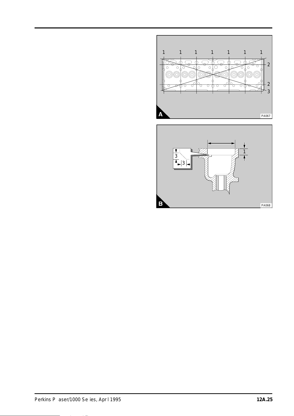
Maximum permissible distortion of cylinder
a
a
a
a
a
a
aaa
aaa
aaa
aaa
aaa
aaa
aaa
aaa
aaa
a
a
a
a
a
a
aaa
aaa
aaa
aaa
aaa
aaa
a
a
a
a
a
a
a
a
a
a
a
a
a
a
a
a
a
a
a
a
a
a
a
a
aaa
aaa
aaa
a
a
a
a
a
a
head (A)
CYLINDER HEAD ASSEMBLY 12
Four cylinder engines
A1 . . . . 0,08 mm (0.003 in)
A2 . . . . 0,15 mm (0.006 in)
A3 . . . . 0,15 mm (0.006 in)
Six cylinder engines
A1 . . . . 0,13 mm (0.005 in)
A2 . . . . 0,25 mm (0.010 in)
A3 . . . . 0,25 mm (0.010 in)
Dimensions of recesses for valve seat inserts
(B)
Inlet
B1 . . . . 7,19/7,32 mm (0.283/0.288 in)
B2 . . . . 51,22/51,24 mm (2.0165/2.0175 in)
B3 . . . . Radius 0,38 mm (0.015 in) maximum
Exhaust
B1 . . . . 9,52/9,65 mm (0.375/0.380 in)
B2 . . . . 42,62/42,65 mm (1.6780/1.6790 in)
B3 . . . . Radius 0,38 mm (0.015 in) maximum
1
1
1
1
1
1
1
3
2
2
3
PA067
2
1
3
3
PA068
Perkins Phaser/1000 Series, April 1995 12A.25
Page 46
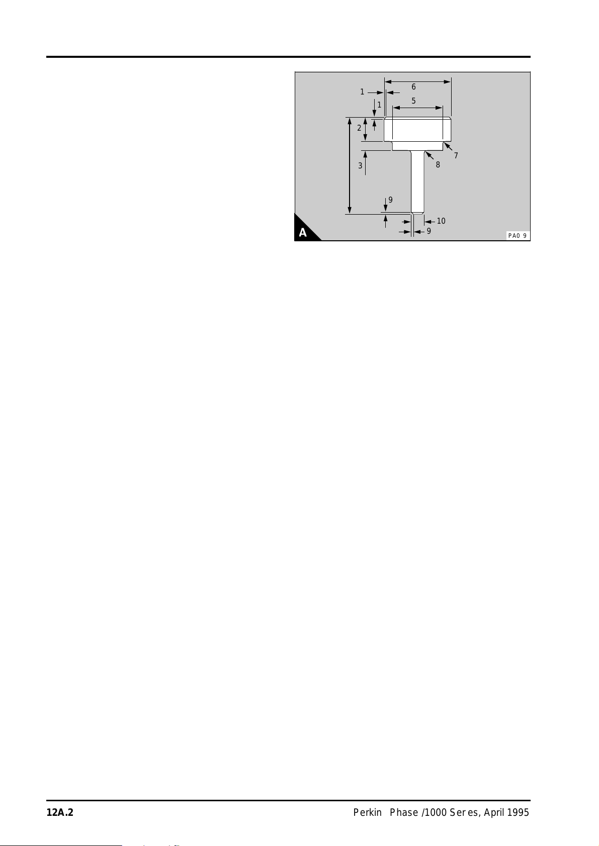
12 CYLINDER HEAD ASSEMBLY
a
a
a
a
aaa
aaa
a
a
a
a
a
a
a
a
a
a
a
a
aaa
aaa
aaa
aaa
a
a
a
a
a
a
a
a
aaa
aaa
aaa
aaa
a
a
a
a
Valve seat insert tool (A)
Inlet (for 45° valves)
A1 . . . . . 1,59 mm (0.063 in)
A2 . . . . . 19,05 mm (0.750 in)
A3 . . . . . 6,35 mm (0.250 in)
A4 . . . . . 76,20 mm (3.00 in)
A5 . . . . . 37,26/37,28 mm (1.467/1.468 in)
A6 . . . . . 51,00/51,23 mm (2.008/2.017 in)
A7 . . . . . 0,79 mm (0.031 in)
A8 . . . . . 1,59 mm (0.063 in)
A9 . . . . . 1,59 mm (0.063 in)
A10 . . . . 9,45/9,47 mm (0.372/0.373 in)
Inlet (for 31° valves)
A1 . . . . . 1,59 mm (0.063 in)
A2 . . . . . 19,05 mm (0.750 in)
A3 . . . . . 3,00 mm (0.118 in)
A4 . . . . . 76,20 mm (3.00 in)
A5 . . . . . 35,30/35,60 mm (1.390/1.402 in)
A6 . . . . . 43,94/43,99 mm (1.730/1.732 in)
A7 . . . . . 0,79 mm (0.031 in)
A8 . . . . . 1,59 mm (0.063 in)
A9 . . . . . 1,59 mm (0.063 in)
A10 . . . . 9,45/9,47 mm (0.372/0.373 in)
1
1
6
5
2
7
3
4
8
9
10
9
PA069
Exhaust (for 45° valves)
A1 . . . . . 1,59 mm (0.063 in)
A2 . . . . . 19,05 mm (0.750 in)
A3 . . . . . 7,92 mm (0.312 in)
A4 . . . . . 76,20 mm (3.00 in)
A5 . . . . . 32,58/32,84 mm (1.283/1.293 in)
A6 . . . . . 42,39/42,62 mm (1,669/1.678 in)
A7 . . . . . 0,79 mm (0.031 in)
A8 . . . . . 1,59 mm (0.063 in)
A9 . . . . . 1,59 mm (0.063 in)
A10 . . . . 9,45/9,47 mm (0.372/0.373 in)
12A.26 Perkins Phaser/1000 Series, April 1995
Page 47

CYLINDER HEAD ASSEMBLY 12
Valve guides
Inside diameter . . . . . . . . . . . . . . . . . . . . . . . . . . . . . . . . . . . . . . . 9,51/9,56 mm (0.3744/0.3764 in)
Outside diameter . . . . . . . . . . . . . . . . . . . . . . . . . . . . . . . . . . . . 15,90/15,91 mm (0.6260/0.6265 in)
Interference fit of valve guide in cylinder head . . . . . . . . . . . . . . . . . . 0,03/0,07 mm (0.0012/0.0027 in)
Full length:
- Inlet . . . . . . . . . . . . . . . . . . . . . . . . . . . . . . . . . . . . . . . . . . . . . . . . . . . . . . 57,94 mm (2.281 in)
- Exhaust . . . . . . . . . . . . . . . . . . . . . . . . . . . . . . . . . . . . . . . . . . . . . . . . . . . . 61,10 mm (2.406 in)
Protrusion from bottom of recess for valve spring . . . . . . . . . . . . . . . . . . . . . . . . 15,10 mm (0.594 in)
Double valve springs - outer
Fitted length . . . . . . . . . . . . . . . . . . . . . . . . . . . . . . . . . . . . . . . . . . . . . . . . . . . . . 35,8 mm (1.41 in)
Load at fitted length . . . . . . . . . . . . . . . . . . . . . . . . . . . . . . . . . . 176/195 N (39.5/43.7 lbf) 18/20 kgf
Number of active coils . . . . . . . . . . . . . . . . . . . . . . . . . . . . . . . . . . . . . . . . . . . . . . . . . . . . . . . 3.6
Number of damper coils . . . . . . . . . . . . . . . . . . . . . . . . . . . . . . . . . . . . . . . . . . . . . . . . . . . . . . . . 1
Direction of coils . . . . . . . . . . . . . . . . . . . . . . . . . . . . . . . . . Left hand - damper coil to cylinder head
Double valve springs - inner
Fitted length . . . . . . . . . . . . . . . . . . . . . . . . . . . . . . . . . . . . . . . . . . . . . . . . . . . . . 34,0 mm (1.34 in)
Load at fitted length . . . . . . . . . . . . . . . . . . . . . . . . . . . . . . . . . . . . . . . 89/104 N (20/23 lbf) 9/11 kgf
Number of active coils . . . . . . . . . . . . . . . . . . . . . . . . . . . . . . . . . . . . . . . . . . . . . . . . . . . . . . . 4.9
Number of damper coils . . . . . . . . . . . . . . . . . . . . . . . . . . . . . . . . . . . . . . . . . . . . . . . . . . . . . . . . 1
Direction of coils . . . . . . . . . . . . . . . . . . . . . . . . . . . . . . . . Right hand - damper coil to cylinder head
Single valve springs
Fitted length . . . . . . . . . . . . . . . . . . . . . . . . . . . . . . . . . . . . . . . . . . . . . . . . . . . . . 40,0 mm (1.57 in)
Load at fitted length . . . . . . . . . . . . . . . . . . . . . . . . . . . . . . . . 312/344 N (70.1/77.3 lbf) 31,8/35,1 kgf
Number of active coils . . . . . . . . . . . . . . . . . . . . . . . . . . . . . . . . . . . . . . . . . . . . . . . . . . . . . . . 4.5
Number of damper coils . . . . . . . . . . . . . . . . . . . . . . . . . . . . . . . . . . . . . . . . . . . . . . . . . . . . . . . . 0
Direction of coils . . . . . . . . . . . . . . . . . . . . . . . . . . . . . . . . . . . . . . . . . . . . . . . . . . . . . . . Left hand
Perkins Phaser/1000 Series, April 1995 12A.27
Page 48

12 CYLINDER HEAD ASSEMBLY
Tappets
Diameter of tappet stem . . . . . . . . . . . . . . . . . . . . . . . . . . . . . . . 18,99/19,01 mm (0.7475/0.7485 in)
Diameter of tappet bore in cylinder block . . . . . . . . . . . . . . . . . . . 19,05/19,08 mm (0.7500/0.7512 in)
Clearance of tappet in cylinder block . . . . . . . . . . . . . . . . . . . . . . . . . 0,04/0,09 mm (0.0015/0.0037 in
Rocker shaft
Outside diameter . . . . . . . . . . . . . . . . . . . . . . . . . . . . . . . . . . . . 19,01/19,04 mm (0.7485/0.7495 in)
Rocker levers and bushes
Diameter of parent bore for bush . . . . . . . . . . . . . . . . . . . . . . . . . 22,23/22,26 mm (0.8750/0.8762 in)
Outside diameter of bush . . . . . . . . . . . . . . . . . . . . . . . . . . . . . . 22,28/22,31 mm (0.8770/0.8785 in)
Interference fit of bush in rocker lever . . . . . . . . . . . . . . . . . . . . . 0,020/0,089 mm (0.0008/0.0035 in)
Internal diameter of fitted bush when reamed . . . . . . . . . . . . . . . . 19,06/19,10 mm (0.7505/0.7520 in)
Clearance between rocker lever bush and rocker shaft . . . . . . . . . . . . 0,03/0,09 mm (0.001/0.0035 in)
Maximum permissible clearance between
rocker lever bush and rocker shaft . . . . . . . . . . . . . . . . . . . . . . . . . . . . . . . . . . . 0,13 mm (0.005 in)
12A.28 Perkins Phaser/1000 Series, April 1995
Page 49

PISTON AND CONNECTING ROD ASSEMBLIES 13
Piston and connecting rod assemblies13
General description. . . . . . . . . . . . . . . . . . . . . . . . . . . . . . . . . . . . . . . . . 13A.02
Big end bearing
13A-01To remove and to fit . . . . . . . . . . . . . . . . . . . . . . . . . . . . . . . . 13A.03
13A-02To inspect . . . . . . . . . . . . . . . . . . . . . . . . . . . . . . . . . . . . . . . . 13A.04
Piston and connecting rod assembly
13A-03To remove and to fit. . . . . . . . . . . . . . . . . . . . . . . . . . . . . . . . . 13A.05
13A-03ATo check the piston height above the cylinder block. . . . . . . . . . 13A.08
13A-03BTo check the height grade of a Fastram piston. . . . . . . . . . . . . . 13A.09
Piston rings
13A-04To remove and to fit. . . . . . . . . . . . . . . . . . . . . . . . . . . . . . . . . 13A.10
Piston and connecting rod assembly
13A-05To dismantle and to assemble. . . . . . . . . . . . . . . . . . . . . . . . . . 13A.11
Piston and piston rings
13A-06To inspect. . . . . . . . . . . . . . . . . . . . . . . . . . . . . . . . . . . . . . . . 13A.12
Connecting rod
13A-07To inspect. . . . . . . . . . . . . . . . . . . . . . . . . . . . . . . . . . . . . . . . 13A.13
Small end bush
13A-08To remove and to fit. . . . . . . . . . . . . . . . . . . . . . . . . . . . . . . . . 13A.13
Piston cooling jets
13A-09To remove and to fit. . . . . . . . . . . . . . . . . . . . . . . . . . . . . . . . . 13A.14
13A-10To check the jet alignment. . . . . . . . . . . . . . . . . . . . . . . . . . . . 13A.14
Data and dimensions. . . . . . . . . . . . . . . . . . . . . . . . . . . . . . . . . . . . . . . 13A.15
Perkins Phaser/1000 Series, April 1995 13A.01
Page 50
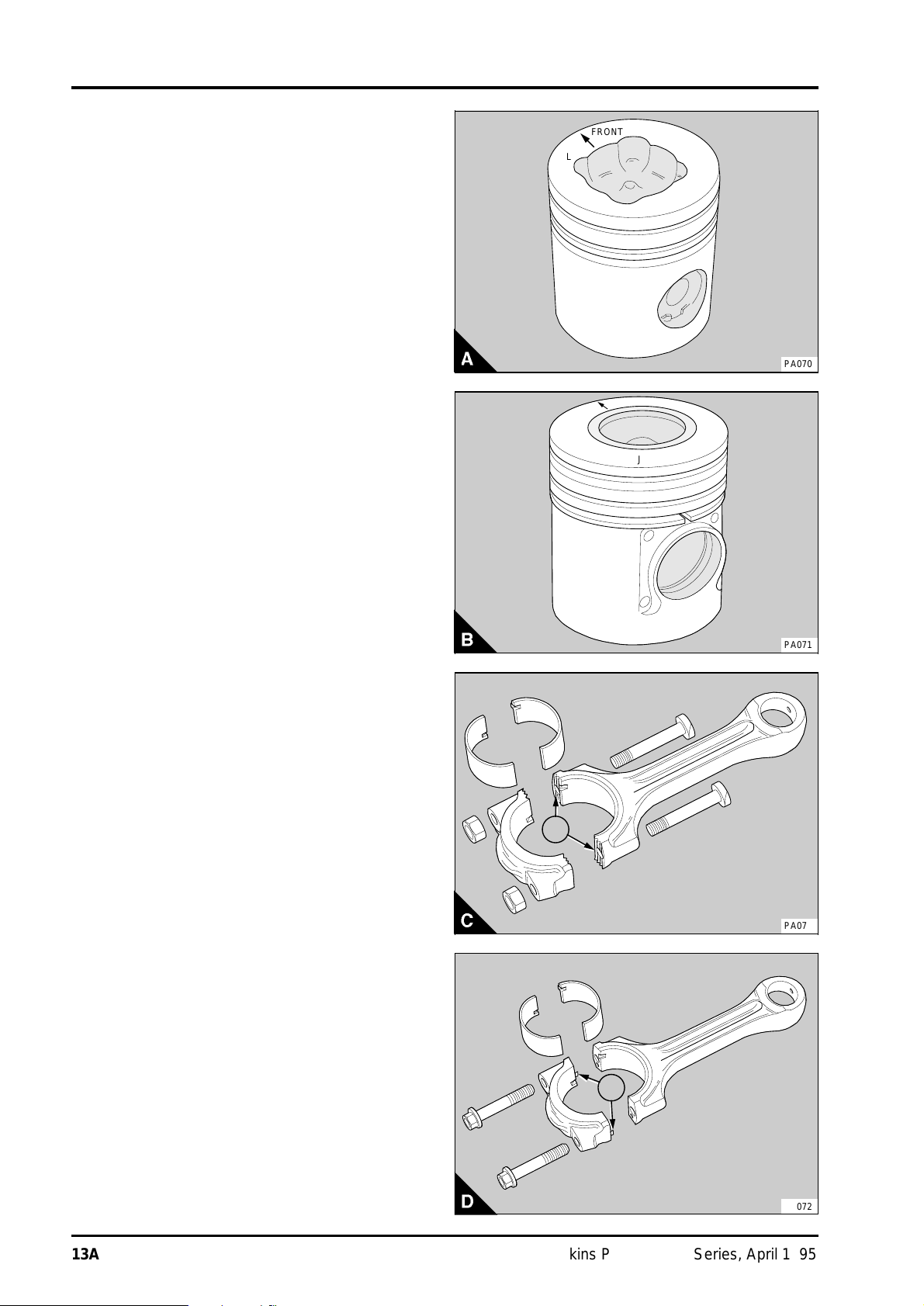
13 PISTON AND CONNECTING ROD ASSEMBLIES
aaaaaaa
a
a
a
a
a
a
a
a
a
a
aaa
aaa
aaa
aaa
aaa
aaa
aaa
1
PA072
General description
The pistons used in Phaser and 1000 Series
engines have either a "Quadram" (A) or a
"Fastram" (B) combustion chamber in the top of
the piston. These combustion chambers are
designed to give an efficient mix of fuel and air.
The latest engines have pistons, with a "Fastram"
combustion chamber and are available with different
height grades.
The pistons have two compression rings and an oil
control ring. The groove for the top ring has a hard
metal insert to reduce wear of the groove. Axial
location of the fully floating gudgeon pin is by
circlips.
Expansion controlled pistons have a steel insert in
the piston skirt.
Turbocharged engines which are rated higher than
2300 rev/min have an anodised area on the top
face of the piston.
Turbocharged engines have cooling jets fitted in the
cylinder block to spray lubricating oil onto the inner
surface of the pistons.
The connecting rods are machined from "H"
section forgings of molybdenum steel. The
connecting rods of turbocharged engines have
wedge shaped small ends. Generally, the location
of the bearing caps to the connecting rods is made
by serrations (C1) and the cap is retained by two
nuts and bolts (C).
On some turbocharged engines, used in vehicle
applications, the location of the bearing cap to the
connecting rod is made by dowels (D1) fitted in the
bearing cap (D). The faces of these connecting
rods and caps are flat and the caps are retained by
two setscrews.
Note: Always use the engine identification number
to order new parts.
aaaaa
FRONT
L
PA070
J
PA071
1
13A.02 Perkins Phaser/1000 Series, April 1995
PA073
Page 51

PISTON AND CONNECTING ROD ASSEMBLIES 13
Big end bearing To remove and to fit13A-01
To remove
1 Drain the engine lubricating oil.
2Remove the lubricating oil sump, operation
19A-03.
3 Remove the lubricating oil strainer and suction
pipe, operation 19A-04 or remove the balancer unit,
operation 14A-10.
4 Rotate the crankshaft until the relevant
connecting rod is at its lowest position.
5 Release the nuts and remove the bearing cap.
Remove the bolts from the connecting rod. If the
bearing cap is retained by setscrews, the location
of the bearing cap will be by two dowels. To
remove these bearing caps, release the setscrews
by approximately four rotates. Lightly hit the heads
of the setscrews with a soft face hammer to
separate the connecting rod from the bearing cap.
Remove the setscrews and the bearing cap.
6 Remove the lower half of the shell bearing from
the cap, but keep it with its relevant cap.
7 Carefully push the connecting rod up the cylinder
bore just enough to allow access to the upper half
of the shell bearing. Remove the bearing from the
connecting rod. Keep the bearings from the
connecting rod and cap together.
Caution: Do not allow the connecting rod to hit the
piston cooling jet, if fitted.
Perkins Phaser/1000 Series, April 1995 13A.03
Page 52
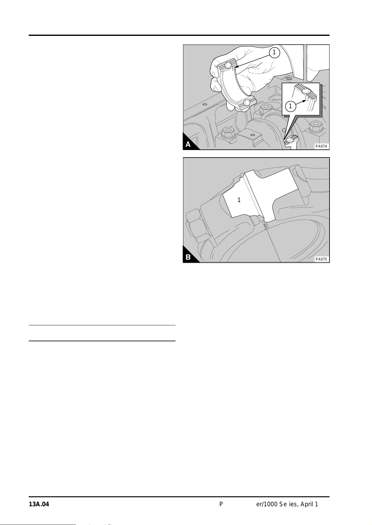
13 PISTON AND CONNECTING ROD ASSEMBLIES
aaa
aaa
aaa
a
a
a
a
a
a
a
a
a
a
a
a
a
a
aaa
aaa
aaa
To fit
1 Clean the bearing faces of the connecting rod
and the crank pin.
2 If the cap has dowels for location on the
connecting rod, ensure that the dowel protrusion is
3,0/4,5 mm (0.12/0.18 in) above the cap faces.
Clean the complete bearing and lubricate the
bearing surface and the crank pin with clean engine
lubricating oil. Fit the upper half of the shell bearing
to the connecting rod; ensure that the location tag
is fitted correctly in its recess (A1). Fit the
connecting rod to the crank pin; ensure that the
assembly number on the connecting rod is on the
same side as the other connecting rods.
3 Clean, lubricate and fit the lower half of the shell
bearings into the cap; ensure that the location tag is
fitted correctly in its recess (A1). Fit the connecting
rod bolts with the flat side of the head of the bolts
towards the connecting rod. Fit the cap to the
connecting rod. Ensure that the assembly number
on the cap is the same as that on the connecting
rod and that both of the assembly numbers are on
the same side (B).
4 Tighten the fasteners gradually and evenly to the
recommended torque of 155 Nm (114 lbf ft)
15,8 kgf m for setscrews, or 125 Nm (92 lbf ft)
12,7 kgf m for nuts.
5 Ensure that the crankshaft rotates freely.
6 Fit the lubricating oil strainer and suction pipe,
operation 19A-04 or fit the balancer unit, operation
14A-10.
7Fit the lubricating oil sump, operation 19A-03 and
fill the sump to the correct level with lubricating oil
of an approved grade.
1
1
PA074
1
1
PA075
To inspect13A-02
Check the bearings and the crank pin for wear or
other damage.
13A.04 Perkins Phaser/1000 Series, April 1995
Page 53

PISTON AND CONNECTING ROD ASSEMBLIES 13
Piston and connecting rod To remove and to fit13A-03
To remove
1 Drain the lubricating oil and the cooling system.
2Remove the cylinder head assembly, operation
12A-07.
3 Remove all carbon from the top of the bores of
the cylinder liners.
4Remove the lubricating oil sump, operation
19A-03.
5 Remove the lubricating oil strainer and suction
pipe, operation 19A-04, or remove the balancer
unit, operation 14A-10.
6 Remove the big end caps and the big end
bearings from the connecting rods, operation
13A-01.
Caution: Do not allow the connecting rods to hit
the piston cooling jets, if fitted. If a cooling jet is hit,
check its alignment, operation 13A-10, and renew
it, if necessary.
7 Turn the connecting rods 90° to prevent contact
with the piston cooling jets. Push the pistons and
the connecting rods out through the top of the
cylinder liners. Keep the bearings and caps
together to ensure that they can be fitted in their
original positions.
8 Inspect the crank pins for damage.
Perkins Phaser/1000 Series, April 1995 13A.05
Page 54
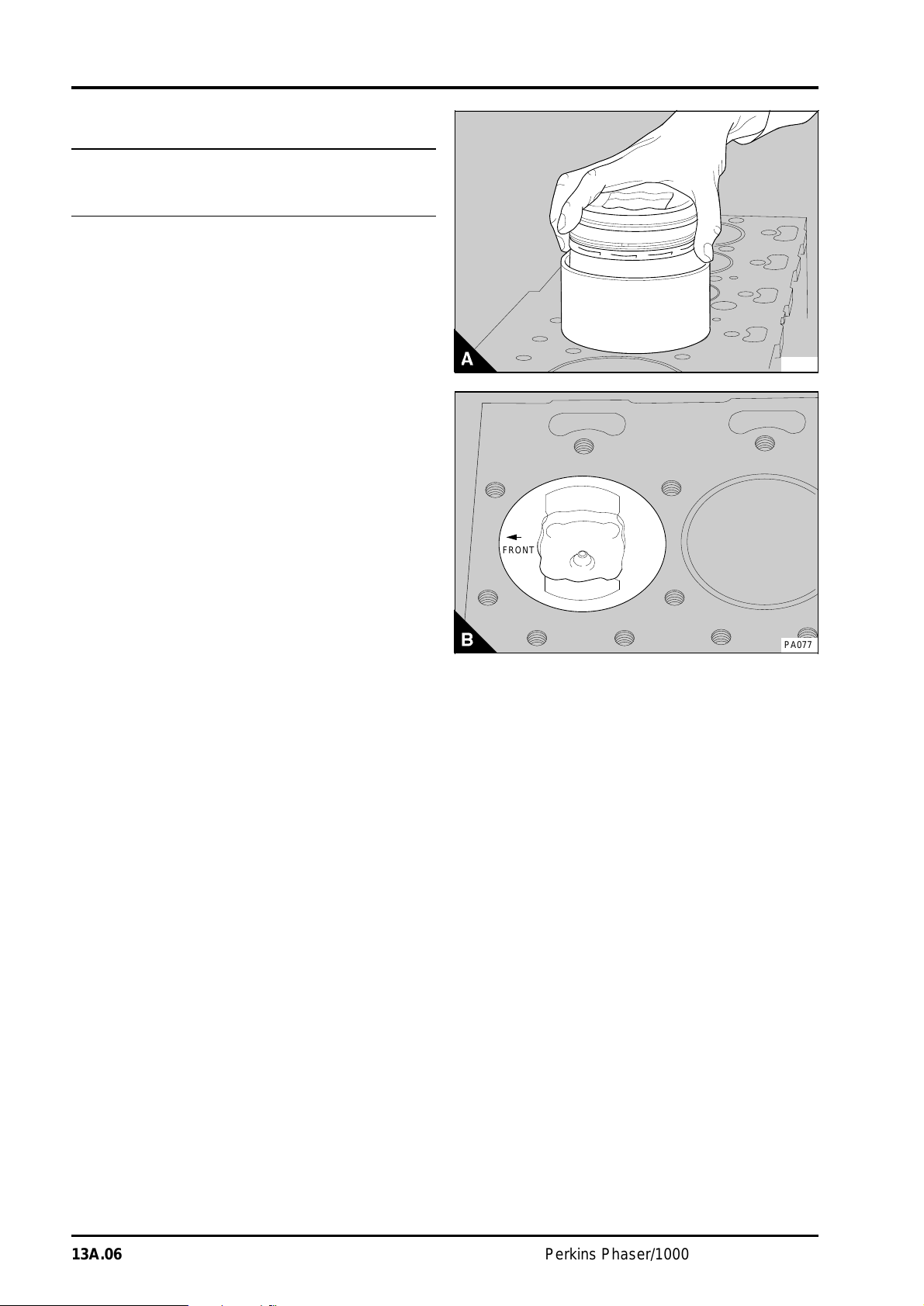
13 PISTON AND CONNECTING ROD ASSEMBLIES
aaaaaaa
a
a
a
a
a
a
To fit
Special tools:
Piston replacer tool, PD.206
1 Ensure that the piston, the cylinder bore, the
crank pin and the big end of the connecting rod are
clean. Lubricate the piston and the cylinder liner
with clean engine lubricating oil.
2 Rotate the crankshaft until the relevant crank pin
is at its lowest position. Lubricate the crank pin with
clean engine lubricating oil.
3 Fit the upper half of the shell bearings to the
connecting rod. Ensure that the location tag is fitted
correctly in its recess. Lubricate the bearing with
clean engine lubricating oil.
4 Put the piston replacer tool in position at the top
of the relevant cylinder. The tool has a tapered bore
to compress the piston rings when the piston and
connecting rod assembly is fitted. Ensure that the
smaller end of the tapered bore is towards the face
of the cylinder block.
5 Put the piston ring gaps 120° apart. Pass the
connecting rod through the piston replacer tool and
allow the piston to enter the tool. The arrow or
"FRONT" mark on the top of the piston must be
towards the front of the engine. In this position the
combustion bowl in the top of the piston will be
towards the fuel injection pump side of the engine.
6 Push the piston and connecting rod assembly
through the piston replacer tool (A) and onto the
crank pin. If piston cooling jets are fitted, the piston
and connecting rod assembly must be rotated to
ensure that the connecting rod will not hit the piston
cooling jet as the assembly is fitted. When the
connecting rod has passed the piston cooling jet,
rotate the connecting rod until the arrow or
"FRONT" mark on top of the piston is towards the
front of the engine (B).
aaaaa
aaaaa
FRONT
aaaaa
PA076
1
PA077
13A.06 Perkins Phaser/1000 Series, April 1995
Page 55

PISTON AND CONNECTING ROD ASSEMBLIES 13
7 Clean the connecting rod cap and the lower half
of the shell bearings. Fit the bearing to the cap;
ensure that the location tag is fitted correctly in its
recess. Lubricate the bearing with clean engine
lubricating oil. Fit the cap and ensure that the
assembly number is the same as that on the
connecting rod and that the numbers are on the
same side. Fit the fasteners; ensure that the flat
side of the head of the bolts is towards the
connecting rod. When the fasteners are nuts, new
nuts must be fitted. Tighten the fasteners gradually
and evenly to the recommended torque of 155 Nm
(114 lbf ft) 15,8 kgf m for setscrews, or 125 Nm
(92 lbf ft) 12,7 kgf m for nuts.
8 Check that the crankshaft will rotate freely.
9 Check the piston height above the top face of
the cylinder block, operation 13A-05.
10 Fit the lubricating oil strainer and suction pipe,
operation 19A-04 or fit the balancer unit, operation
14A-10.
11Fit the lubricating oil sump, operation 19A-03.
12Fit the cylinder head assembly, operation
12A-07.
13 Fill the sump to the correct level with lubricating
oil of an approved grade.
14 Fill the cooling system.
Perkins Phaser/1000 Series, April 1995 13A.07
Page 56
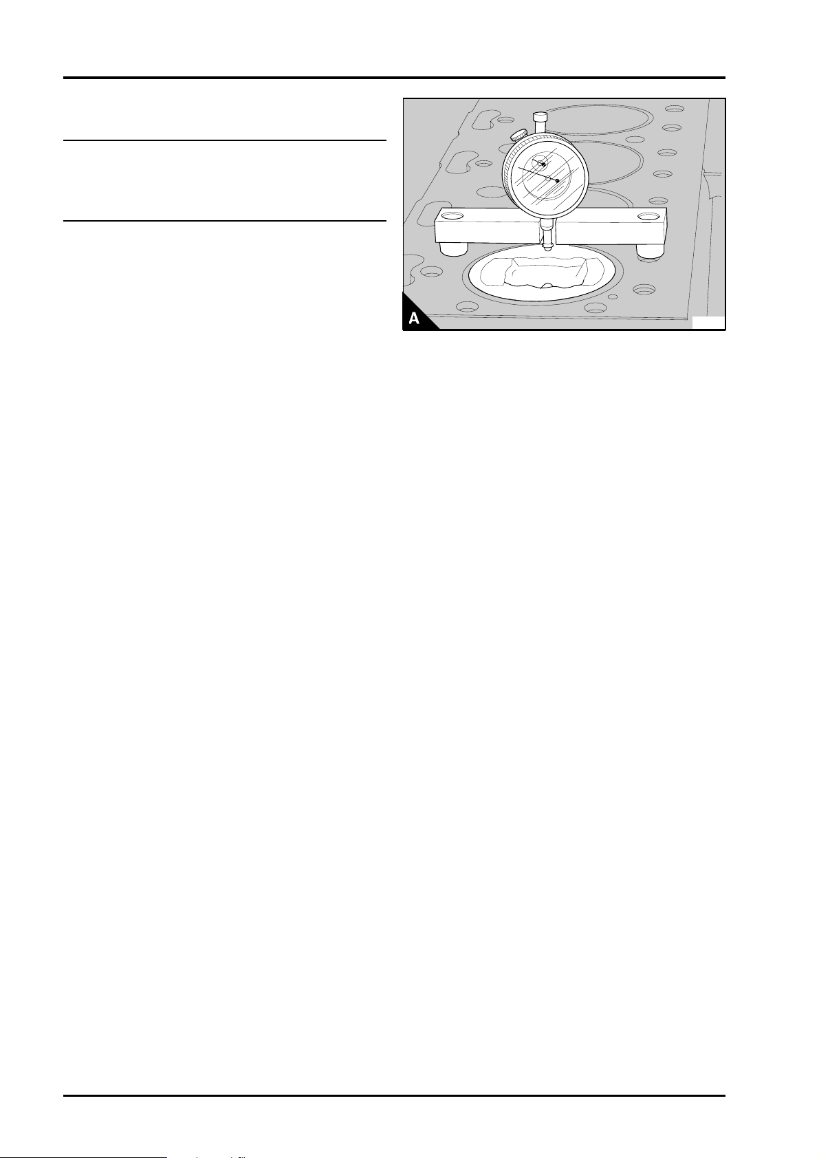
13 PISTON AND CONNECTING ROD ASSEMBLIES
To check the piston height above the cylinder block13A-03A
Special tools:
Piston height tool, PD.41D
Dial gauge for use with PD.41D, PD.208
Put the piston height tool on the face of the cylinder
block and rotate the gauge dial to the zero position.
Rotate the crankshaft until the piston is
approximately at top dead centre (TDC). Carefully
put the tool over the top of the piston with the
plunger of the gauge in contact with the piston
above the axis of the gudgeon pin (A). Rotate the
crankshaft to ensure that the piston is at the
highest position and make a note of the gauge
indication.
For engines fitted with "Quadram" pistons, the
piston height above the face of the cylinder block
should be 0,14/0,36 mm (0.005/0.014 in).
For engines fitted with "Fastram" pistons, grades A
to L, the piston height above the top face of the
cylinder block should be 0,38/0,50 mm
(0.015/0.020 in)
Notes:
• Two "Quadram" piston heights can be used in
the factory: "H" - high, "L" - low. In service only
"L" pistons are supplied. If an "L" piston is used
instead of an "H" piston, the height may be up to
0,19 mm (0.0075 in) below the bottom limit.
• The top of the piston should not be machined.
• If the original piston is used, ensure that it is
assembled to the correct connecting rod and is
used in the original cylinder.
PA078
13A.08 Perkins Phaser/1000 Series, April 1995
Page 57
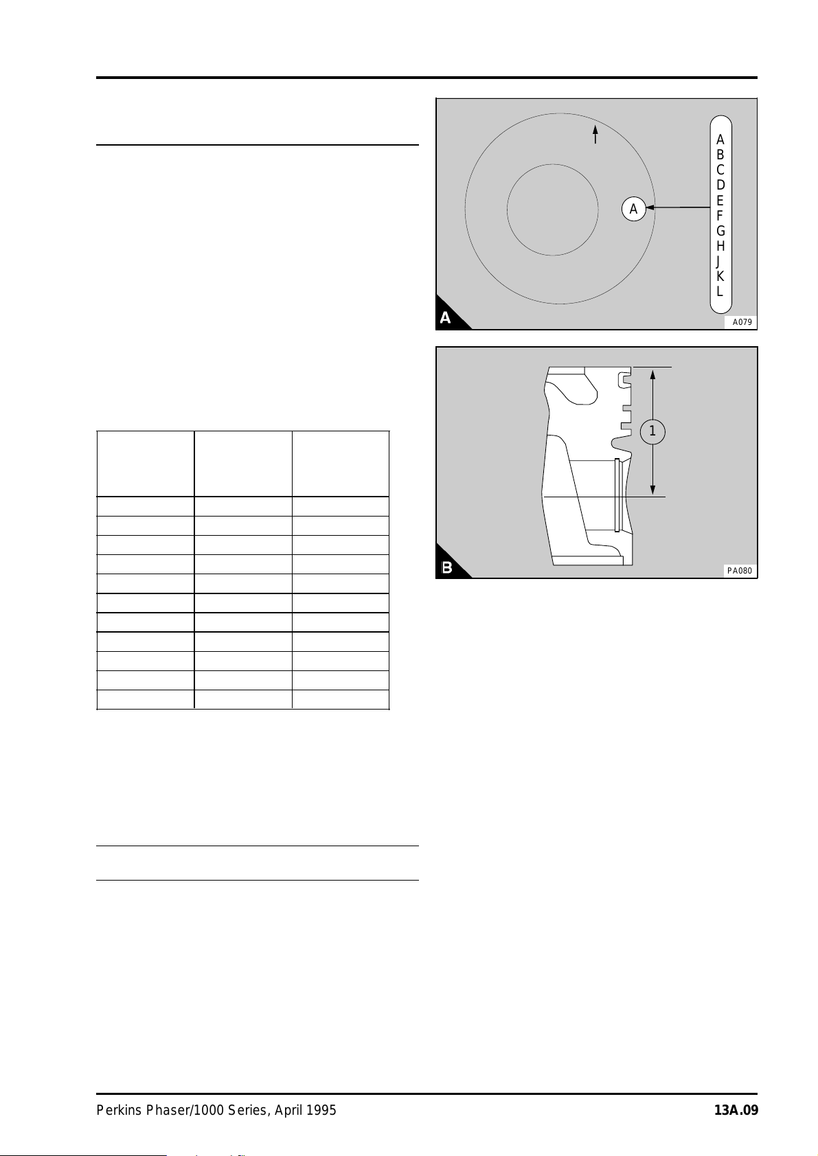
PISTON AND CONNECTING ROD ASSEMBLIES 13
aaa
aaa
aaa
aaa
aaa
aaa
aaa
aaa
aaa
aaa
aaa
aaa
aaa
aaa
aaa
aaa
aaa
aaa
aaa
aaa
aaa
aaa
aaa
aaa
aaa
aaa
aaa
aaa
aaa
aaa
aaa
aaa
aaa
aaa
aaa
a
a
a
a
a
a
To check the height grade
of a "Fastram" piston13A-03B
For engines fitted with earlier "Fastram "pistons
there are five height grades (A to E) of piston in
production and in service.
The latest "Fastram" pistons are supplied in six
height grades (F to L) in production and in service.
Identification of the height grade is by the letter for
each piston which is stamped on the top of the
piston (A). The letter A or F is the highest grade
and letter E or L is the lowest grade. The difference
between the grades is 0,045 mm (0.0018 in).
If a new piston is fitted, ensure that it is of the
correct height grade. The height grade can be
checked by measurement, from the centre of the
gudgeon pin to the top of the piston (B1). The
dimensions for each grade are listed in the table
below:
Piston grade
letter
Piston height
dimension
(mm)
Latest
equivalent
grade
A
B
C
D
A
E
F
G
H
J
K
L
PA079
1
A* 70,334 G
B* 70,289 H
C* 70,244 J
D* 70,199 K
E* 70,154 L
F 70,391
G 70,345
H 70,299
J 70,253
K 70,207
L 70,161
* Earlier engines
Note: The earlier piston grades A to E are now not
supplied as a part. The latest equivalent grades G
to L shown in the table above are to be used
instead.
Piston rings
To remove and to fit13A-04
PA080
The piston used in the Phaser and 1000 Series
engines have two compression rings and an oil
control ring. All the piston rings are above the
gudgeon pin. Piston rings have different design
features. To ensure that the correct type is
obtained always use the engine identification
number to order new parts.
Perkins Phaser/1000 Series, April 1995 13A.09
Page 58
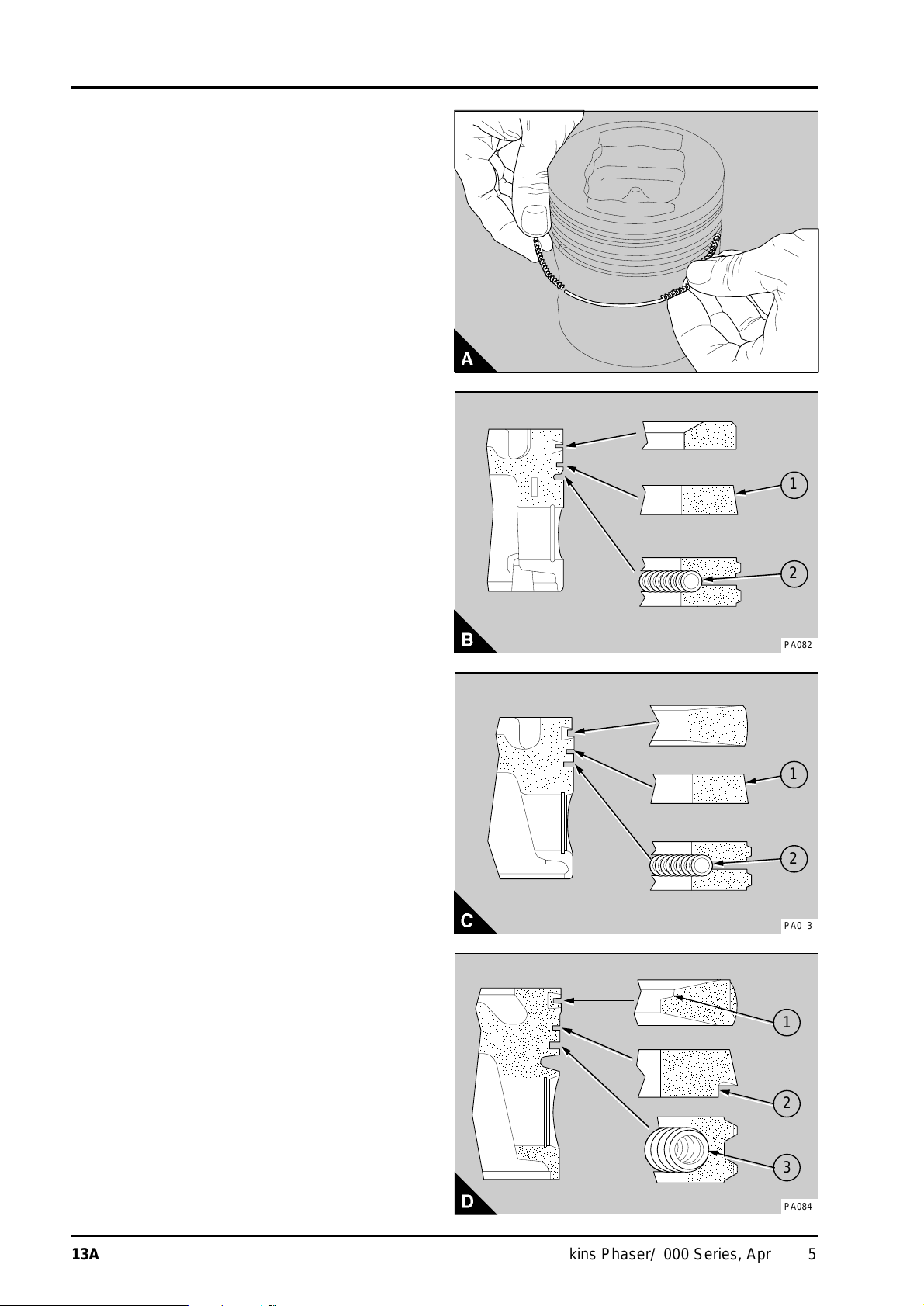
13 PISTON AND CONNECTING ROD ASSEMBLIES
aaa
aaa
aaa
aaa
aaa
aaa
aaa
aaa
aaa
aaa
aaa
aaa
aaa
a
a
a
a
a
a
1
a
a
a
a
a
a
2
a
a
a
a
a
a
3
PA084
Caution: Only expand the ring gaps enough to
ensure that the ends of the rings do not damage
the piston when the ring is removed or put into
position.
To remove
Remove the piston rings with a suitable ring
expander. Keep the rings with their relevant piston.
To fit
Use a suitable piston ring expander to fit the piston
rings.
1 Fit the spring of the oil control ring in the bottom
groove with the latch pin inside both ends of the
spring (A). Fit the oil control ring over the spring
(B2, C2 or D3). Ensure that the ring gap is at 180°
to the latch pin.
2 Fit the cast iron ring with the taper face
(B1 or C1) to the second groove with the word
"TOP", or the manufacturer's symbol, towards the
top of the piston.
New second rings have a green identification mark
which must be on the left of the ring gap when the
ring is fitted and the piston is upright.
The second ring on some engines has an outside
step (D2) at the bottom of the tapered face.
3 Fit the chromium plated top ring, the
manufacturer's symbol or the word 'TOP' must be
towards the top of the piston.
New top rings have a red or blue identification mark
which must be on the left of the ring gap when the
ring is fitted and the piston is upright.
The top ring on some engines has an internal step
(D1) on the top face.
4 Ensure that the ring gaps are 120° apart.
PA081
1
2
PA082
1
2
PA083
13A.10 Perkins Phaser/1000 Series, April 1995
Page 59
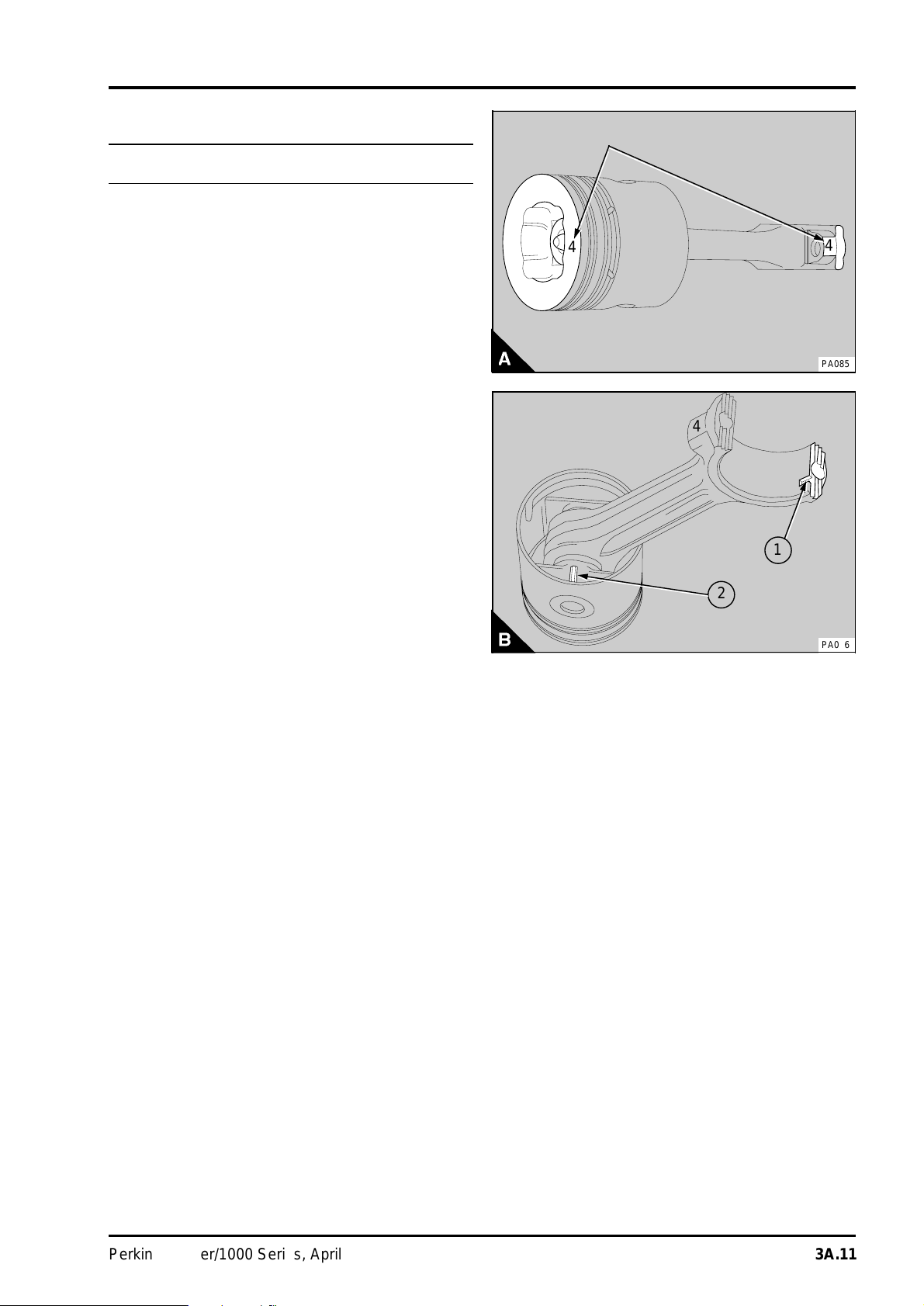
PISTON AND CONNECTING ROD ASSEMBLIES 13
aaa
aaa
aaa
a
a
a
a
a
a
aaa
aaa
aaa
a
a
a
a
a
a
a
a
a
a
a
a
Piston and connecting rod assembly To dismantle and to assemble13A-05
To dismantle
1Remove the piston rings, operation 13A-04.
2 Remove the circlips which retain the gudgeon
pin.
3 Put a mark on the piston to indicate the cylinder
number as shown on the connecting rod. Put the
mark on the piston on the same side as the mark
on the big end to ensure that they are assembled
correctly (A).
4 Push the gudgeon pin out by hand. If the
gudgeon pin is tight, heat the piston to 40/50°C
(100/120°F) for easy removal of the gudgeon pin.
To assemble
1 Clean the bore of the small end bush and
lubricate it with clean engine lubricating oil.
2 Fit a new circlip in the circlip groove of one of
the gudgeon pin bosses. Ensure that it fits correctly
in the groove.
3 With the piston upside down, put the connecting
rod in position with the recess for the location of
the big end bearing (B1) on the same side as the
lug on the gudgeon pin boss (B2). If the original
piston is used, ensure that it is assembled to the
correct connecting rod and is used in the original
cylinder. Engines with "Fastram" pistons have six
piston height grades, if a new piston is fitted,
ensure that it is of the correct height grade, see
operation 13A-03.
4 Lubricate the gudgeon pin bosses with clean
engine lubricating oil and push in the gudgeon pin
towards the circlip. If the gudgeon pin is a tight fit in
the piston, heat the piston to 40/50°C (100/120°F)
before the gudgeon pin is fitted.
5 Fit a new circlip in the groove in the other
gudgeon pin boss. Ensure that it fits correctly in the
groove.
6Fit the piston rings, operation 13A-04.
4
4
PA085
4
1
2
PA086
Perkins Phaser/1000 Series, April 1995 13A.11
Page 60
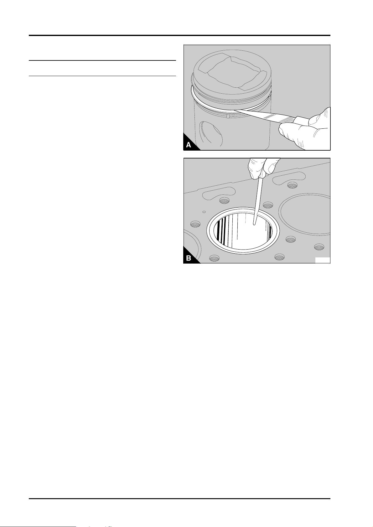
13 PISTON AND CONNECTING ROD ASSEMBLIES
Piston and piston rings
To inspect13A-06
1 Check the piston for wear and other damage.
2 Check that the piston rings are free to move in
their grooves and that the the rings are not broken.
3Remove the piston rings, operation 13A-04, and
clean the piston ring grooves and the piston rings.
4 Fit new piston rings in the grooves and check for
wear of the grooves with feeler gauges (A).
Compare the piston ring clearance in the groove to
that given for new components in the data and
dimensions and renew the piston, if necessary.
Note: Some pistons have a tapered top groove and
the piston ring is wedge shaped (13A.10 C/D);
when this occurs the top piston ring clearance
cannot be checked by this method.
5 Clean all carbon from the top of the cylinder
liners. Fit the piston rings in the top part of the
cylinder liner and measure the ring gap with feeler
gauges (B). The coil spring must be fitted to the oil
control ring when the gap of this piston ring is
measured. The piston ring gaps for new
components are given in the data and dimensions.
PA087
PA088
13A.12 Perkins Phaser/1000 Series, April 1995
Page 61
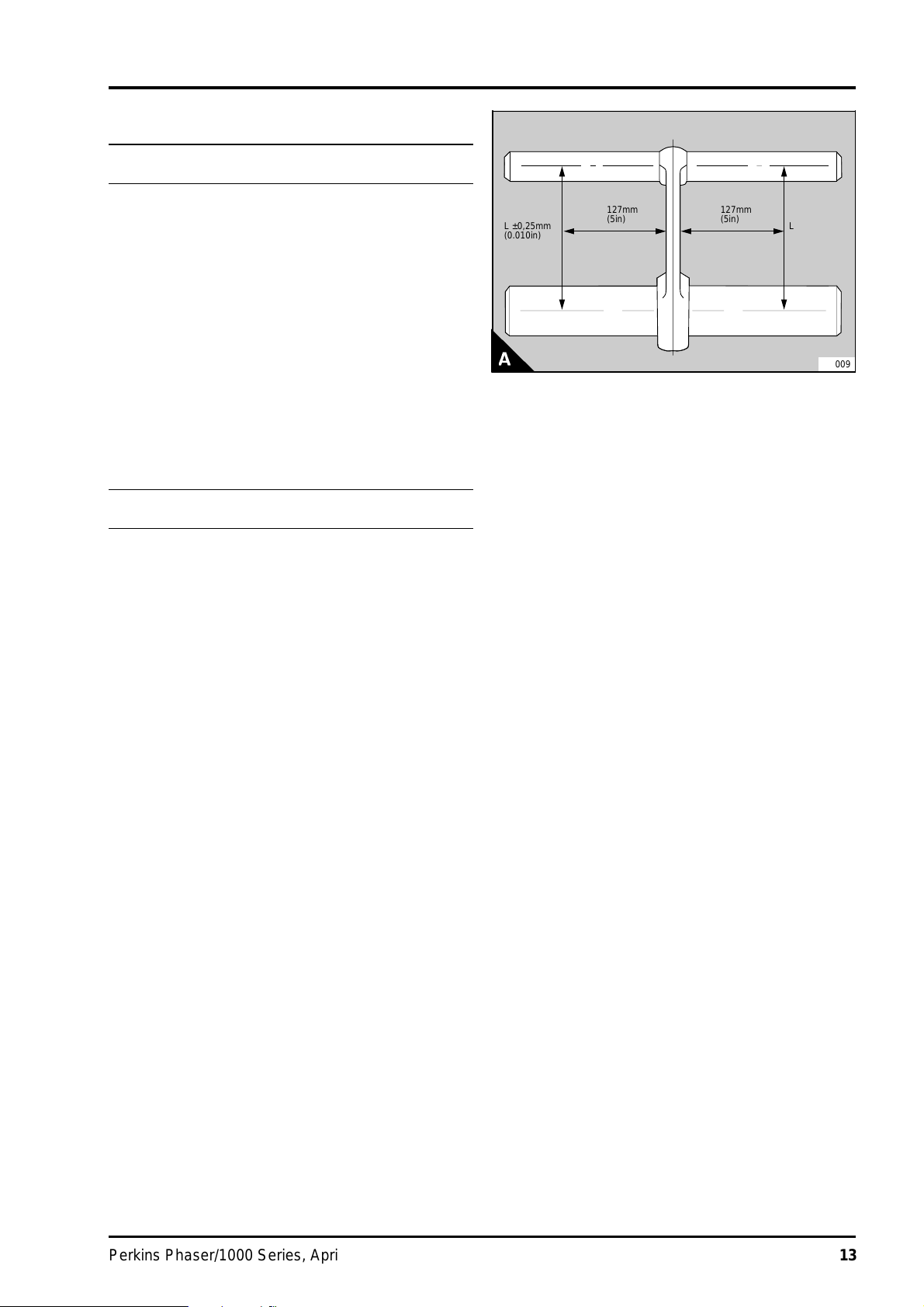
PISTON AND CONNECTING ROD ASSEMBLIES 13
aaaaaaaaa
a
a
a
a
a
aaaaaaa
a
a
a
a
aaaaaaa
a
a
a
a
aaaaaaaaa
a
a
a
a
a
Connecting rod To inspect13A-07
1 Check the connecting rod for distortion (A).
Note: The large and small end bores must be
square and parallel with each other within the limits
of +/- 0,25 mm (0.010 in) measured 127 mm
(5.0 in) each side of the connecting rod axis on a
test mandrel. With the small end bush fitted, the
limits are reduced to +/- 0,06 mm (0.0025 in).
2 Check the small end bush for wear or for other
damage and renew it, if necessary.
3 Check the fit of the gudgeon pin in the small end
bush and check the gudgeon pin for wear, see the
data and dimensions.
Small end bush To remove and to fit13A-08
1 Press out the old bush with a suitable adaptor.
2 Clean the connecting rod bore and remove any
sharp edges.
3 Press in the new bush. Ensure that the
lubrication hole in the bush is on the same side as,
and is aligned with, the hole in the top of the
connecting rod.
4 Ream the bush to get the correct clearance
between the gudgeon pin and the bush, see the
data and dimensions.
Note: On turbocharged engines the small end is
wedge shaped. After the small end bush has been
fitted, machine the bush to the shape of the small
end and remove any sharp edges.
L ±0,25mm
aaaaaaa
aaaaaaa
(0.010in)
aaaaa
127mm
aaaaa
(5in)
a
a
aaaaa
aaaaa
127mm
aaaaa
(5in)
aaaaa
L ±0,25mm
aaaaaaa
aaaaaaa
(0.010in)
PG009
a
a
Perkins Phaser/1000 Series, April 1995 13A.13
Page 62
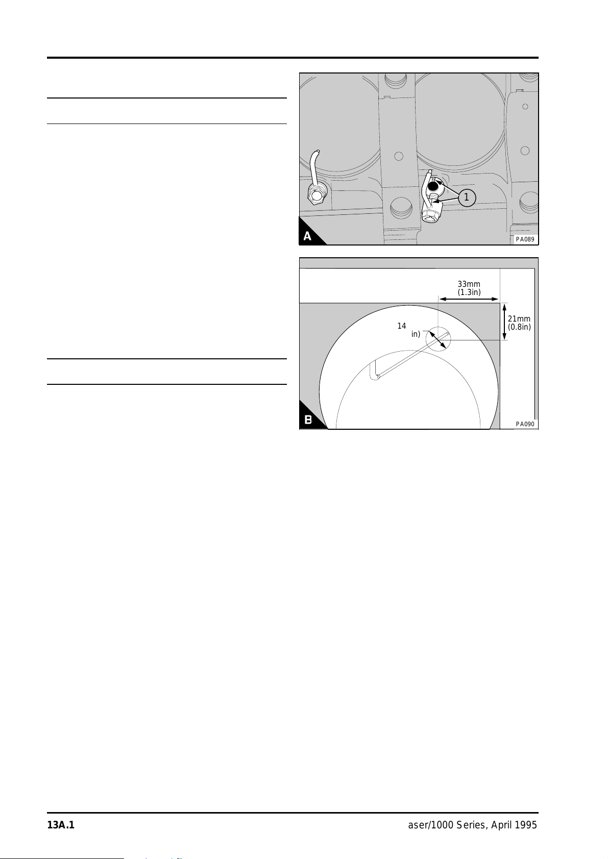
13 PISTON AND CONNECTING ROD ASSEMBLIES
a
a
a
a
a
a
aaaaaaa
a
a
a
a
a
a
aaaaaaa
a
a
a
a
a
a
aaaaaaa
a
a
a
a
a
a
a
a
Piston cooling jets
To remove and to fit13A-09
To remove
Release the valve assembly and remove the piston
cooling jet assembly (A).
Note: The crankshaft is removed in A to show
clearly the piston cooling jet.
To fit
1 Check that the ball moves freely against spring
pressure in the valve assembly and that the jet tube
is not damaged. Renew the valve assembly and/or
the body as necessary.
2 Fit the piston cooling jet; ensure that the
assembly is fitted correctly on the dowel in the
cylinder block. Tighten the valve assembly to
20 Nm (15 lbf ft) 2,0 kgf m.
aaaaa
14mm
aaaaa
aaaaa
(0.5in)
1
33mm
aaaaa
aaaaa
(1.3in)
aaaaa
PA089
aaaaa
21mm
aaaaa
aaaaa
(0.8in)
aaaaa
To check the jet alignment13A-10
Insert a 1,70 mm (0.067 in) diameter rod, of
suitable length, into the jet. If a suitable rod is not
available, reduce the end of a thicker rod to
1,70 mm (0.067 in) diameter for a length of
16,00 mm (0.630 in). When the rod is inserted into
the jet it must extend out of the top of the cylinder
within the area shown in B.
PA090
13A.14 Perkins Phaser/1000 Series, April 1995
Page 63

PISTON AND CONNECTING ROD ASSEMBLIES 13
Data and dimensions
Note: This information is given as a guide for personnel engaged on engine overhauls. The dimensions
which are shown are those which are mainly used in the factory. The information applies to all engines,
unless an engine type code is shown.
Pistons - Naturally aspirated engines:
Type . . . . . . . . . . . . . . . . . . . . . . . . . . . . . . . . . . . . . . . . . . "Quadram" combustion bowl, controlled
expansion, inserted top ring groove
Diameter of bore for gudgeon pin . . . . . . . . . . . . . . . . . . . . . . 34,928/34,934 mm (1.3751/1.3754 in)
Height of piston above top face of cylinder block . . . . . . . . . . . . . . . . . . 0,14/0,36 mm (0.005/0.014 in)
Width of groove for top ring . . . . . . . . . . . . . . . . . . . . . . . . . . . . . . . . . 2,57/2,59 mm (0.101/0.102 in)
Width of groove for second ring . . . . . . . . . . . . . . . . . . . . . . . . . . . . . . 2,55/2,57 mm (0.100/0.101 in)
Width of groove for third ring . . . . . . . . . . . . . . . . . . . . . . . . . . . . . . 4,03/4,06 mm (0.1587/0.1598 in)
Pistons - Turbocharged engines:
Type . . . . . . . . . . . . . . . . . . . . . . . . . . . . . . . . . . "Quadram" combustion bowl, controlled expansion,
inserted top ring groove, reduced diameter top land
Diameter of bore for gudgeon pin . . . . . . . . . . . . . . . . . . . . . . . 38,103/38,109 mm (1.500/1.5004 in)
Height of piston above top face of cylinder block . . . . . . . . . . . . . . . . . . 0,14/0,36 mm (0.005/0.014 in)
Width of groove for top ring . . . . . . . . . . . . . . . . . . . . . . . . . . . . . . . . . . . . . . . . . . . . . . . . Tapered
Width of groove for second ring . . . . . . . . . . . . . . . . . . . . . . . . . . . . 2,56/2,58 mm (0.1008/0.1016 in)
Width of groove for third ring . . . . . . . . . . . . . . . . . . . . . . . . . . . . . . 4,04/4,06 mm (0.1591/0.1598 in)
Pistons - Turbocharged AE, YE, AD* engines:
Type . . . . . . . . . . . . . . . . . . . . . . . . . . . . . . . . . . "Fastram" combustion bowl, controlled expansion,
inserted top ring groove, high top ring groove
Diameter of bore for gudgeon pin . . . . . . . . . . . . . . . . . . . . . 39,7003/39,7009 mm (1.5355/1.5358 in)
Difference between height grades . . . . . . . . . . . . . . . . . . . . . . . . . . . . . . . . . . 0,046 mm (0.0018 in)
Height of piston above top face of cylinder block . . . . . . . . . . . . . . . . . 0,38/0,50 mm (0.015/0.020 in)
Width of groove for top ring . . . . . . . . . . . . . . . . . . . . . . . . . . . . . . . . . . . . . . . . . . . . . . . . Tapered
Width of groove for second ring . . . . . . . . . . . . . . . . . . . . . . . . . . . . 2,56/2,58 mm (0.1008/0.1016 in)
Width of groove for third ring . . . . . . . . . . . . . . . . . . . . . . . . . . . . . . 4,04/4,06 mm (0.1591/0.1598 in)
Piston cooling jets - Turbocharged engines:
Valve open pressure . . . . . . . . . . . . . . . . . . . . . . . . . . . . . 178/250 kPa (26/36 lbf/in
2
) 1,8/2,6 kgf/cm
* 110 Ti and 135 Ti AD lists are fitted with pistons which are designed for use in emission controlled areas.
Some of these pistons are non-expansion controlled.
2
Perkins Phaser/1000 Series, April 1995 13A.15
Page 64

13 PISTON AND CONNECTING ROD ASSEMBLIES
Piston rings - Naturally aspirated engines:
Top compression ring . . . . . . . . . . . . . . . . . . . . . . . . . . . . . . . . Barrel face, molybdenum insert, with
a chamfer at the top of the inner face
Second compression ring . . . . . . . . . . . . . . . . . . . . . . . . . . . . . . . . . . . . . . . . . Taper face, cast iron
Oil scraper ring . . . . . . . . . . . . . . . . . . . . . . . . . . . . . . . . . . . . . Coil spring loaded, chromium faced
Width of top ring . . . . . . . . . . . . . . . . . . . . . . . . . . . . . . . . . . . . . . . . 2,48/2,49 mm (0.097/0.098 in)
Width of second ring . . . . . . . . . . . . . . . . . . . . . . . . . . . . . . . . . . . . . 2,48/2,49 mm (0.097/0.098 in)
Width of third ring . . . . . . . . . . . . . . . . . . . . . . . . . . . . . . . . . . . . . 3,98/3,99 mm (0.1566/0.1571 in)
Clearance of top ring in groove . . . . . . . . . . . . . . . . . . . . . . . . . . . . . . 0,08/0,11 mm (0.003/0.004 in)
Clearance of second ring in groove . . . . . . . . . . . . . . . . . . . . . . . . . . . 0,06/0,09 mm (0.002/0.003 in)
Clearance of third ring in groove . . . . . . . . . . . . . . . . . . . . . . . . . . . . . 0,04/0,08 mm (0.002/0.003 in)
Gap of top ring . . . . . . . . . . . . . . . . . . . . . . . . . . . . . . . . . . . . . . . . . 0,40/0,85 mm (0.016/0.033 in)
Gap of second ring . . . . . . . . . . . . . . . . . . . . . . . . . . . . . . . . . . . . . . 0,30/0,76 mm (0.012/0.030 in)
Gap of third ring . . . . . . . . . . . . . . . . . . . . . . . . . . . . . . . . . . . . . . . . 0,38/0,84 mm (0.015/0.033 in)
Piston rings - Turbocharged engines:
Top compression ring . . . . . . . . . . . . . . . . . . . . . . . . . . . . . . . Barrel face, molybdenum insert, wedge
Second compression ring . . . . . . . . . . . . . . . . . . . . . . . . . . . . . . . . . . . . . . . . . Taper face, cast iron
Oil scraper ring . . . . . . . . . . . . . . . . . . . . . . . . . . . . . . . . . . . . . . Coil spring loaded, chromium face
Width of top ring . . . . . . . . . . . . . . . . . . . . . . . . . . . . . . . . . . . . . . . . . . . . . . . . . . . . . . . . . Wedge
Width of second ring . . . . . . . . . . . . . . . . . . . . . . . . . . . . . . . . . . . . . 2,48/2,49 mm (0.097/0.098 in)
Width of third ring . . . . . . . . . . . . . . . . . . . . . . . . . . . . . . . . . . . . . . . 3,98/3,99 mm (0.156/0.157 in)
Clearance of top ring in groove . . . . . . . . . . . . . . . . . . . . . . . . . . . . . . . . . . . . . . . . . . . . . . . Wedge
Clearance of second ring in groove . . . . . . . . . . . . . . . . . . . . . . . . . . . 0,07/0,11 mm (0.003/0.004 in)
Clearance of third ring in groove . . . . . . . . . . . . . . . . . . . . . . . . . . . . . 0,05/0,08 mm (0.002/0.003 in)
Gap of top ring . . . . . . . . . . . . . . . . . . . . . . . . . . . . . . . . . . . . . . . . . 0,35/0,80 mm (0.014/0.031 in)
Gap of top ring with internal step . . . . . . . . . . . . . . . . . . . . . . . . . . . . . 0,35/0,70 mm (0.014/0.028 in)
Gap of second ring . . . . . . . . . . . . . . . . . . . . . . . . . . . . . . . . . . . . . . 0,30/0,76 mm (0.012/0.030 in)
For second rings with outside step . . . . . . . . . . . . . . . . . . . . . . . . . . . 0,40/0,85 mm (0.016/0.033 in)
Gap of third ring . . . . . . . . . . . . . . . . . . . . . . . . . . . . . . . . . . . . . . . . 0,38/0,84 mm (0.015/0.033 in)
13A.16 Perkins Phaser/1000 Series, April 1995
Page 65

PISTON AND CONNECTING ROD ASSEMBLIES 13
Connecting rods - Naturally aspirated engines:
Type . . . . . . . . . . . . . . . . . . . . . . . . . . . . . . . . . . . . . . . . . . . . . 'H' section, square shape small end
Location of cap to connecting rod . . . . . . . . . . . . . . . . . . . . . . . . . . . . . . . . . . . . . . . . . . Serrations
Diameter of parent bore for big end . . . . . . . . . . . . . . . . . . . . . . . 67,21/67,22 mm (2.6460/2.6465 in)
Diameter of parent bore for small end . . . . . . . . . . . . . . . . . . . . . . . 38,89/38,92 mm (1.531/1.532 in)
Length between centres . . . . . . . . . . . . . . . . . . . . . . . . . . . . . . . 219,05/219,10 mm (8.624/8.626 in)
Connecting rods - Turbocharged engines:
Type . . . . . . . . . . . . . . . . . . . . . . . . . . . . . . . . . . . . . . . . . . . . . 'H' section, wedge shape small end
Location of cap to connecting rod:
- Vehicle applications . . . . . . . . . . . . . . . . . . . . . . . . . . . . . . . . . . . . . . . . Flat joint face with dowels
- Non-vehicle applications . . . . . . . . . . . . . . . . . . . . . . . . . . . . . . . . . . . . . . . . . . . . . . . . Serrations
Diameter of parent bore for big end . . . . . . . . . . . . . . . . . . . . . . . 67,21/67,22 mm (2.6460/2.6465 in)
Diameter of parent bore for small end . . . . . . . . . . . . . . . . . . . . . . . 42,07/42,09 mm (1.656/1.657 in)
Length between centres . . . . . . . . . . . . . . . . . . . . . . . . . . . . . . . 219,05/219,10 mm (8.624/8.626 in)
Connecting rod bearings
Type:
- Naturally aspirated engines: . . . . . . . . . . . . . . . . . . . . . . . Steel back, aluminium/tin bearing material
- Turbocharged engines: . . . . . . . . . . . . . . . . Steel back, lead bronze bearing material with lead finish
Width:
- Naturally aspirated engines: . . . . . . . . . . . . . . . . . . . . . . . . . . . . . 31,62/31,88 mm (1.245/1.255 in)
- Turbocharged engines: . . . . . . . . . . . . . . . . . . . . . . . . . . . . . . . . . 31,55/31,88 mm (1.240/1.255 in)
Thickness at centre of bearings:
- Naturally aspirated engines: . . . . . . . . . . . . . . . . . . . . . . . . . . . 1,835/1,842 mm (0.0723/0.0725 in)
- Turbocharged engines: . . . . . . . . . . . . . . . . . . . . . . . . . . . . . . . 1,835/1,844 mm (0.0723/0.0726 in)
Bearing clearance:
- Naturally aspirated engines: . . . . . . . . . . . . . . . . . . . . . . . . . . . 0,035/0,081 mm (0.0014/0.0032 in)
- Turbocharged engines: . . . . . . . . . . . . . . . . . . . . . . . . . . . . . . . 0,030/0,081 mm (0.0012/0.0032 in)
Available undersize bearings . . . . . . . -0,25 mm (-0.010 in); -0,51 mm (-0.020 in); -0,76 mm (-0.030 in)
Perkins Phaser/1000 Series, April 1995 13A.17
Page 66

13 PISTON AND CONNECTING ROD ASSEMBLIES
Gudgeon pins - Naturally aspirated engines:
Type . . . . . . . . . . . . . . . . . . . . . . . . . . . . . . . . . . . . . . . . . . . . . . . . . . . . . . . . . . . . . . Fully floating
Outside diameter . . . . . . . . . . . . . . . . . . . . . . . . . . . . . . . . . . . 34,920/34,925 mm (1.3748/1.3750 in)
Clearance fit in piston boss . . . . . . . . . . . . . . . . . . . . . . . . . . . . . 0,003/0,014 mm (0.0001/0.0006 in)
Gudgeon pins - Turbocharged engines:
Type . . . . . . . . . . . . . . . . . . . . . . . . . . . . . . . . . . . . . . . . . . . . . . . . . . . . . . . . . . . . . . Fully floating
Outside diameter . . . . . . . . . . . . . . . . . . . . . . . . . . . . . . . . . . . 38,095/38,100 mm (1.4998/1.5000 in)
- AE, YE and 110 Ti and 135 Ti AD lists . . . . . . . . . . . . . . . . . . 39,694/39,700 mm (1.5628/1.5630 in)
Clearance fit in piston boss . . . . . . . . . . . . . . . . . . . . . . . . . . . . . 0,003/0,014 mm (0.0001/0.0006 in)
Small end bushes - Naturally aspirated engines:
Type . . . . . . . . . . . . . . . . . . . . . . . . . . . . . Steel back, lead-bronze or lead-bronze tin bearing material
Outside diameter . . . . . . . . . . . . . . . . . . . . . . . . . . . . . . . . . . . . . . 38,94/39,03 mm (1.535/1.536 in)
Inside diameter (reamed) . . . . . . . . . . . . . . . . . . . . . . . . . . . . . . 34,94/34,96 mm (1.3758/1.3765 in)
Clearance between bush in small end and gudgeon pin . . . . . . . . . 0,020/0,043 mm (0.0008/0.0017 in)
Small end bushes - Turbocharged engines:
Type . . . . . . . . . . . . . . . . . . . . . . . . . . . . . . . . . . . . . . . . . . Steel back, lead bronze bearing material
- AE, YE, and certain AD lists* . . . . . . . . . . . . . . . . . . . . . Steel back, lead bronze tin bearing materials
Outside diameter . . . . . . . . . . . . . . . . . . . . . . . . . . . . . . . . . . . . 42,16/42,19 mm (1.6600/1.6613 in)
Inside diameter (reamed) . . . . . . . . . . . . . . . . . . . . . . . . . . . . . . 38,12/38,14 mm (1.5008/1.5015 in)
- AE, YE and certain AD lists* . . . . . . . . . . . . . . . . . . . . . . . . . . 39,719/39,738 mm (1.5637/1.5645 in)
Clearance between bush in small end and gudgeon pin . . . . . . . . . 0,020/0,043 mm (0.0008/0.0017 in)
- AE, YE . . . . . . . . . . . . . . . . . . . . . . . . . . . . . . . . . . . . . . . . . . 0,010/0,035 mm (0.0004/0.0014 in)
Certain AD lists * . . . . . . . . . . . . . . . . . . . . . . . . . . . . . . . . . . . 0,023/0,044 mm (0.0009/0.0017 in)
*AD lists which are subject to emission legislation
13A.18 Perkins Phaser/1000 Series, April 1995
Page 67

CRANKSHAFT ASSEMBLY 14
Crankshaft assembly14
General description. . . . . . . . . . . . . . . . . . . . . . . . . . . . . . . . . . . . . . . . . 14A.03
Crankshaft pulley
14A-01ATo remove and to fit - four cylinder engine types. . . . . . . . . . . . 14A.04
Crankshaft pulley and damper
14A-01BTo remove and to fit - six cylinder engine types . . . . . . . . . . . . . 14A.05
14A-01CTo inspect. . . . . . . . . . . . . . . . . . . . . . . . . . . . . . . . . . . . . . . . 14A.07
Rear oil seal assembly
14A-02ATo remove and to fit - engines which have the standard seal. . . 14A.08
14A-02BTo remove and to fit - engines which have a flywheel housing
that is oil filled . . . . . . . . . . . . . . . . . . . . . . . . . . . . . . . . . . . . . 14A.09
14A-03ATo renew the rear oil seal - engines which have the standard seal14A.11
14A-03BTo renew the rear oil seals - engines which have a flywheel housing
that is oil filled. . . . . . . . . . . . . . . . . . . . . . . . . . . . . . . . . . . . . 14A.12
Thrust washers
14A-04To check crankshaft end-float. . . . . . . . . . . . . . . . . . . . . . . . . . 14A.14
14A-05To remove and to fit. . . . . . . . . . . . . . . . . . . . . . . . . . . . . . . . . 14A.15
Main bearings
14A-06To remove and to fit (with the crankshaft in position). . . . . . . . . 14A.16
14A-07To inspect. . . . . . . . . . . . . . . . . . . . . . . . . . . . . . . . . . . . . . . . 14A.17
Crankshaft
14A-08To remove and to fit. . . . . . . . . . . . . . . . . . . . . . . . . . . . . . . . . 14A.18
14A-09To inspect. . . . . . . . . . . . . . . . . . . . . . . . . . . . . . . . . . . . . . . . 14A.21
Continued
Perkins Phaser/1000 Series, April 1995 14A.01
Page 68

14 CRANKSHAFT ASSEMBLY
Balancer unit
14A-10To remove and to fit. . . . . . . . . . . . . . . . . . . . . . . . . . . . . . . . . 14A.22
14A-11To dismantle and to assemble. . . . . . . . . . . . . . . . . . . . . . . . . . 14A.23
14A-12To inspect. . . . . . . . . . . . . . . . . . . . . . . . . . . . . . . . . . . . . . . . . 14A.28
14A-13To remove and to fit the needle roller bearings for the drive shaft14A.29
14A-14To remove and to fit the bushes for the balance weights. . . . . . . 14A.30
Data and dimensions. . . . . . . . . . . . . . . . . . . . . . . . . . . . . . . . . . . . . . . . 14A.31
14A.02 Perkins Phaser/1000 Series, April 1995
Page 69
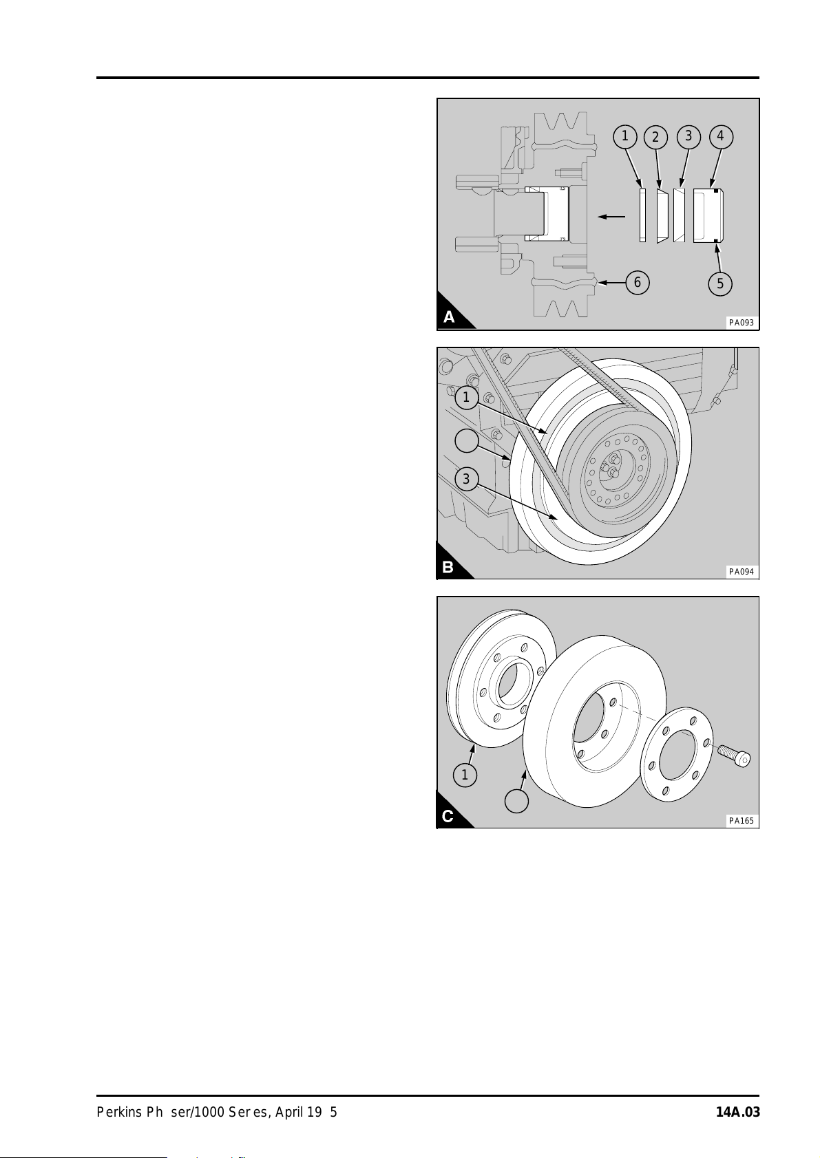
General description
aaa
aaa
aaa
aaa
aaa
aaa
a
a
a
a
a
a
a
a
aaa
aaa
aaa
aaa
aaa
aaa
aaa
aaa
aaa
aaa
aaa
aaa
aaa
aaa
aaa
aaa
aaa
aaa
a
a
a
a
a
a
aaa
aaa
aaa
CRANKSHAFT ASSEMBLY 14
The crankshaft is a chrome-molybdenum forging
which has five main journals for four cylinder
engines and seven main journals for six cylinder
engines.
End-float is controlled by two half thrust washers on
both sides of the centre main bearing.
The main bearings have steel backs with a
aluminium/tin bearing material except the centre
main bearing of six cylinder engines, which has a
bearing material of lead bronze with a lead finish.
The main bearing caps are made of cast iron or
spheroidal graphite (SG) iron.
Note: The bearing material of all the main bearings
used on Phaser 210Ti engines is lead bronze with a
lead finish.
The front and the rear oil seals are Viton lip seals
with a dust lip to the outside of the main lip and
with oil return grooves on the face of the main lip.
Engines which have a flywheel housing that is oil
filled have an arrangement which uses two "Viton"
lip seals. These seals are narrower than the
standard seal and are fitted back to back on the
crankshaft palm. They do not have a dust lip.
Warning! Read the safety precautions for "Viton"
seals on page 10A.08.
The crankshaft pulley of the four cylinder engine,
usually fitted without a damper, is held in position
by a plain thrust block and three setscrews. The
nose of the crankshaft is serrated for location.
The location of the front pulley of six cylinder
engines is by a key in the crankshaft nose and the
pulley is held in position by a tapered rings
arrangement (A).
An integral damper, with a rubber insert (A6) is built
into the pulley of early six cylinder engines and
some four cylinder engines. Later six cylinder
vehicle engines have a separate plate damper
which has an outer plate (B2), bonded by a rubber
insert (B1) to an inner plate (B3) and fastened to
the rear face of the crankshaft pulley. The latest six
cylinder engines have a viscous damper (C2) which
is fastened to the front or rear face of the pulley
(C1). All of the dampers are designed for the
suppression of torsional vibrations in the engine
crankshaft.
A balancer unit is fitted to certain four cylinder
engines which have rigid mountings or which are
part of the chassis or frame. The purpose of the
balancer unit is to reduce the effect of the
out-of-balance forces to an acceptable condition.
4
1
6
3
2
5
PA093
1
2
3
PA094
1
2
PA165
Perkins Phaser/1000 Series, April 1995 14A.03
Page 70
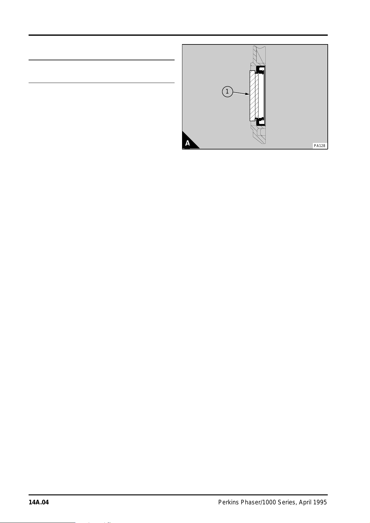
14 CRANKSHAFT ASSEMBLY
aaaaa
a
aaaaa
a
aaaaa
a
aaaaa
a
aaaaa
a
aaaaa
a
aaaaa
a
aaaaa
a
aaaaa
a
aaaaa
a
aaaaa
a
aaaaa
a
aaaaa
a
aaaaa
a
aaaaa
a
aaaaa
a
aaaaa
a
aaaaa
a
aaaaa
a
aaaaa
a
aaaaa
a
aaaaa
a
aaaaa
a
aaaaa
a
aaaaa
a
aaaaa
a
aaa
aaa
aaa
Crankshaft pulley
To remove and to fit - four cylinder
engines14A-01A
On certain engines a water immersion seal (A) is
fitted to the timing case cover, see operation
15A-02. The water immersion seal has a flexible
front lip that protrudes onto the boss of the
crankshaft pulley. The plastic mandrel (A1) supplied
with the seal must be fitted to the seal immediately
the crankshaft pulley is removed. This will ensure
that the front lip of the seal will retain its correct
shape. If the mandrel is not available, use the seal
adaptor PD.170-8 which is part of the seal replacer
tool PD.170.
To remove
1Remove the drive belt(s), operation 23A-04.
2 Release the three setscrews which hold the
pulley and remove the setscrews, the thrust block
and the pulley.
3 Clean the components and check for damage.
Renew damaged components.
To fit
1 Put the pulley in position on the crankshaft.
Lubricate lightly the threads of the setscrews with
engine lubricating oil. Lubricate the main lip of the
seal with clean engine oil. Fit the hub and the
setscrews and tighten the setscrews gradually and
evenly to 115 Nm (85 lbf ft) 11,8 kgf m.
2 Check each setscrew again to ensure that they
are still to the correct torque.
3Fit the drive belt(s), operation 23A-04.
1
PA128
14A.04 Perkins Phaser/1000 Series, April 1995
Page 71
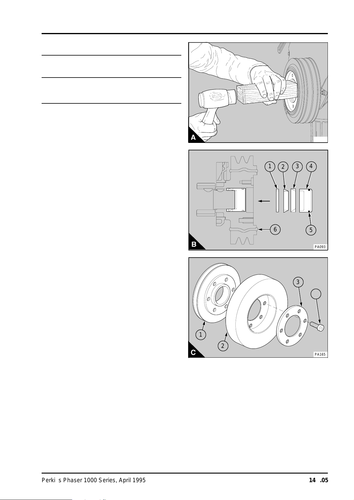
Crankshaft pulley and damper
aaa
aaa
aaa
aaa
aaa
aaa
a
a
a
a
a
a
aaa
aaa
aaa
aaa
aaa
aaa
aaa
aaa
aaa
aaa
aaa
aaa
aaa
aaa
aaa
a
a
a
a
a
a
aaa
aaa
aaa
To remove and to fit - six cylinder
engines 14A-01B
Consumable products:
POWERPART Retainer (oil tolerant)
Caution: A viscous damper (C2) should be
renewed if there is impact damage to the outer
casing or if there is leakage of the viscous fluid
from the cover plate. Check the area around the
holes for the damper fasteners for damage.
To remove
CRANKSHAFT ASSEMBLY 14
PA097
1Remove the drive belts, operation 23A-04.
Warning! The crankshaft pulley and damper
assembly is heavy and must be given support
before removal.
2 Release the fasteners which secure the clamp
ring (C3) for the damper to the pulley, if one is
fitted, and remove the damper.
3 Remove the three setscrews and the thrust block
(B4). If the pulley is not free, do not use an
extractor to remove the pulley. Hold a wooden
block against the inner hub of the pulley and with a
hammer, lightly hit the wooden block towards the
rear (A) to loosen the tapered rings.
To fit
1 If the damper is fitted to the rear face of the
pulley, fit the damper to the pulley with its inner
flange against the rear face of the pulley. If a
viscous damper is fitted, put the damper in position
on the face of the pulley (C1). Fit the clamp ring
(C3) or the washers.
Notes:
• On some engines the viscous damper is fitted to
the rear of the pulley.
• If a clamp ring with a chamfer on the outside
edge of the ring is used, ensure that the chamfer is
towards the damper when the ring is fitted. Clamp
rings may be fitted to viscous or plate dampers.
Apply POWERPART Retainer (oil tolerant) to the
cap screws (A4) for the clamp ring and tighten the
cap screws gradually and evenly to 35 Nm
(26 lbf ft) 3,6 kgf m. For viscous dampers fitted with
M12 setscrews tighten the fasteners to 75 Nm
(55 lb ft) 7,6 kgf m.
4
1
6
3
2
5
PA093
3
4
1
2
PA165
Perkins Phaser/1000 Series, April 1995 14A.05
Page 72
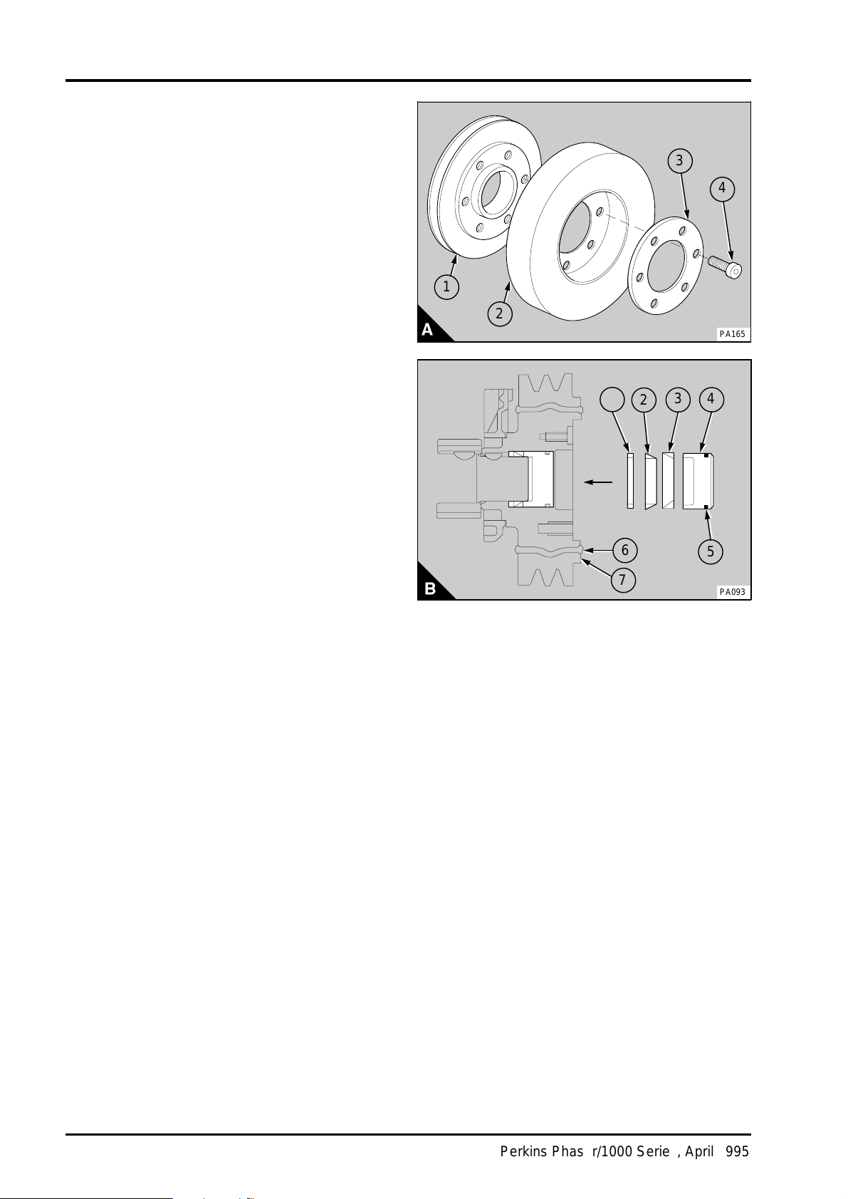
14 CRANKSHAFT ASSEMBLY
aaa
aaa
aaa
a
a
a
a
a
a
aaa
aaa
aaa
aaa
aaa
aaa
a
a
a
a
a
a
a
a
a
a
a
a
aaa
aaa
aaa
a
a
a
a
a
a
a
a
a
a
a
a
aaa
aaa
aaa
a
a
a
a
a
a
a
a
Caution: Do not use a degreasing solution.
2 Clean thoroughly the nose of the crankshaft, the
bore of the pulley and the tapered rings
components. Do not expand the tapered rings.
3 Put the pulley on the crankshaft with the key
engaged and push the pulley towards the rear.
4 Fit the spacer (B1), then the inner ring (B2) and
then the outer ring (B3). Ensure that the ring gaps
are not aligned.
Caution: It can be very difficult to remove the
pulley if the tapered rings are not fitted correctly.
5 Lubricate lightly the "O" ring (B5) and the
threads and the thrust faces of the setscrews with
clean engine oil. Put the thrust block (B4) and
setscrews in position.
6 While the pulley is pressed to the rear, tighten
the setscrews gradually and evenly to 115 Nm
(85 lbf ft) 11,8 kgf m. Apply the torque again to
ensure the pulley is fully tightened.
7Fit the drive belts, operation 23A-04.
3
4
1
2
PA165
4
1
3
2
6
7
5
PA093
14A.06 Perkins Phaser/1000 Series, April 1995
Page 73
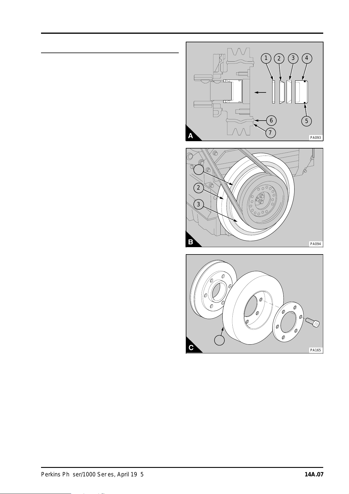
To Inspect14A-01C
aaa
aaa
aaa
aaa
aaa
aaa
a
a
a
a
a
a
a
a
aaa
aaa
aaa
aaa
aaa
aaa
aaa
aaa
aaa
a
a
a
a
a
a
a
a
aaa
aaa
aaa
aaa
aaa
aaa
aaa
aaa
aaa
aaa
aaa
aaa
1 When an integral pulley and damper (A) or a
separate plate damper (B) is fitted. The assembly
should be renewed if:,
• The rubber insert (A6) or (B1) between the hub
and the outer ring is split.
• The rubber insert is damaged by oil or solvents
• There is movement of the pulley or outer ring on
the hub.
Check the area around the holes for the damper
fasteners for cracks or wear.
Caution: Do not use excessive force to lever the
damper away from the engine.
2 Remove any paint or dirt in four positions 90°
apart on the face (A7) or (B2) of the damper, above
the rubber insert. Use a lever to move the damper
forward and eliminate the crankshaft end-float. Fit a
dial test indicator on the front cover of the timing
case. Measure the alignment of the damper face at
four locations, 90° apart. The maximum
permissible difference between the maximum and
minimum figures obtained is:
• Integral pulley and damper 0,18 mm (0.007 in).
• Separate plate damper 0,60 mm (0.024 in).
3 Remove any paint or dirt from the circumference
of the damper. Fit a dial test indicator on the front
cover of the timing case.
4 Rotate the crankshaft slowly one complete
revolution and measure for run-out on the
circumference of the damper with the dial test
indicator. The maximum permissible difference
between the maximum and minimum figures
obtained is:
• Integral pulley and damper 0,12 mm (0.005 in).
• Separate plate damper 0,80 mm (0.032 in).
5 A viscous damper (C1) must be renewed if there
is impact damage to the outer casing or if there is
leakage of the viscous fluid from the cover plate.
Check the area around the holes for the damper
fasteners for damage.
CRANKSHAFT ASSEMBLY 14
4
1
6
7
1
2
3
1
3
2
5
PA093
PA094
PA165
Perkins Phaser/1000 Series, April 1995 14A.07
Page 74
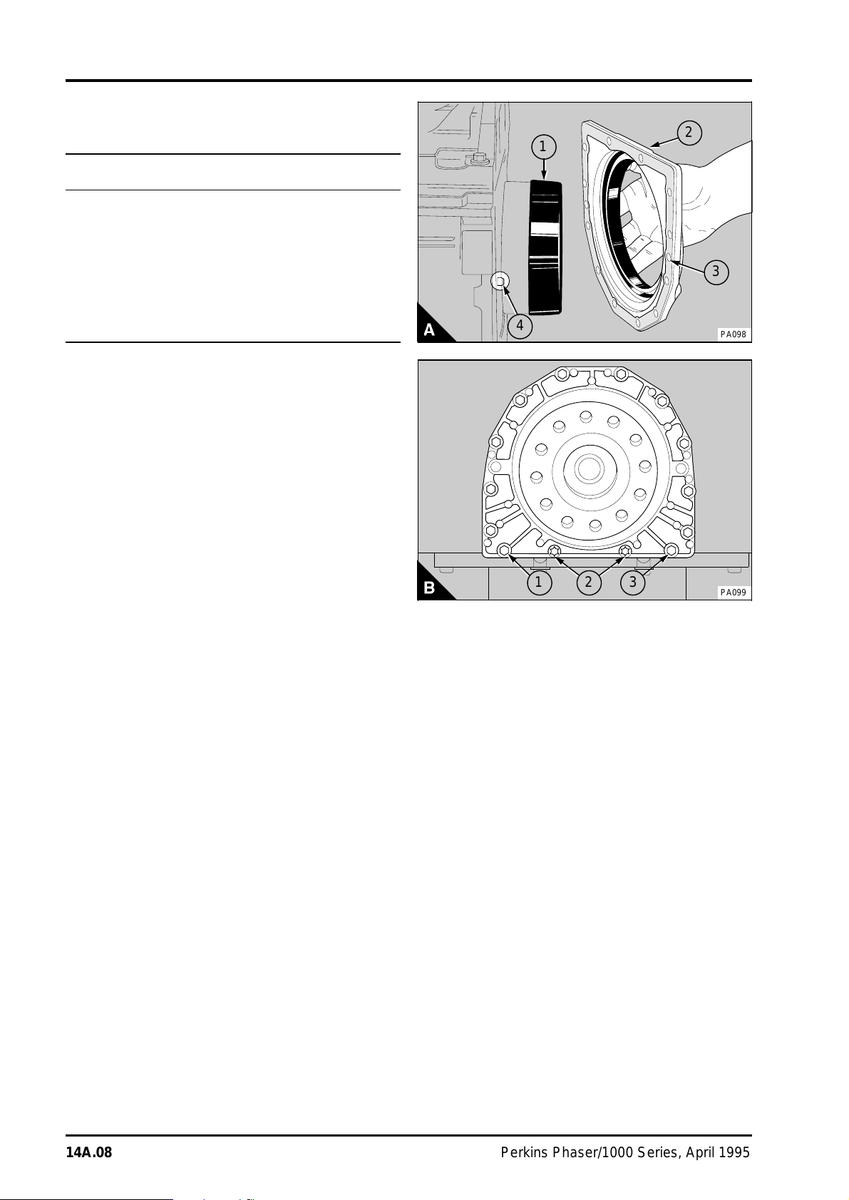
14 CRANKSHAFT ASSEMBLY
aaaaaaaaa
aaaaaaaaa
aaaaaaaaa
aaaaaaaaa
aaaaaaaaa
aaaaaaaaa
aaaaaaaaa
aaaaaaaaa
aaaaaaaaa
aaaaaaaaa
aaaaaaaaa
aaaaaaaaa
aaaaaaaaa
aaaaaaaaa
aaaaaaaaa
aaaaaaaaa
aaaaaaaaa
aaaaaaaaa
aaaaaaaaa
aaaaaaaaa
aaaaaaaaa
aaaaaaaaa
aaaaaaaaa
aaaaaaaaa
a
a
a
a
a
a
aaa
aaa
aaa
a
a
a
a
a
a
a
a
a
a
a
a
aaa
aaa
aaa
aaa
aaa
aaa
aaa
aaa
aaa
Rear oil seal assembly - engines which
have the standard seal
To remove and to fit14A-02A
Special tools:
Replacer tool for rear oil seal, PD.145D
2
1
Consumable products:
POWERPART Threadlock
POWERPART Silicone rubber sealant
1 Remove the drive components from the rear end
of the engine.
2 Remove the flywheel and the flywheel housing,
see section 22.
3 Remove the setscrews and the cap screws from
the housing and remove the housing and seal
assembly.
4 Inspect the seal for wear or for damage to the
main lip and renew the seal, if necessary. If there is
only a small scratch across the lip, renew the seal.
5 Clean the faces of the cylinder block, the oil seal
housing and the crankshaft flange.
6 Check that the seal and the outer circumference
of the crankshaft flange are not damaged. Where a
new seal has been fitted, check that it is in the
correct position in the housing.
7 Ensure that the two dowels (A4) are fitted in the
cylinder block. Put a new joint (A3) in position on
the dowels, no jointing compound is necessary.
8 Put the seal replacer tool on the crankshaft
flange. Lubricate the crankshaft flange, the main lip
of the seal and the seal replacer tool with clean
engine lubricating oil. The lubrication of the seal is
necessary to prevent damage to the seal when the
engine is first started.
9 Put the seal and housing (A2) on the replacer
tool (A1) and carefully push the assembly into
position on the crankshaft flange and onto the
dowels. Remove the tool, fit the setscrews and the
cap screws. Tighten the setscrews to 22 Nm (16 lbf
ft) 2,2 kgf m and tighten the cap screws to 18 Nm
(13 lbf ft) 1,9 kgf m.
Note: On the latest engines two torx screws (B2)
are fitted instead of cap screws. Tighten the torx
screws to 22 Nm (16 lbf ft) 2,2 kgf m. Two extra
setscrews (B1 and B3) have also been fitted to later
engines.
3
4
1
2
3
PA098
PA099
14A.08 Perkins Phaser/1000 Series, April 1995
Page 75
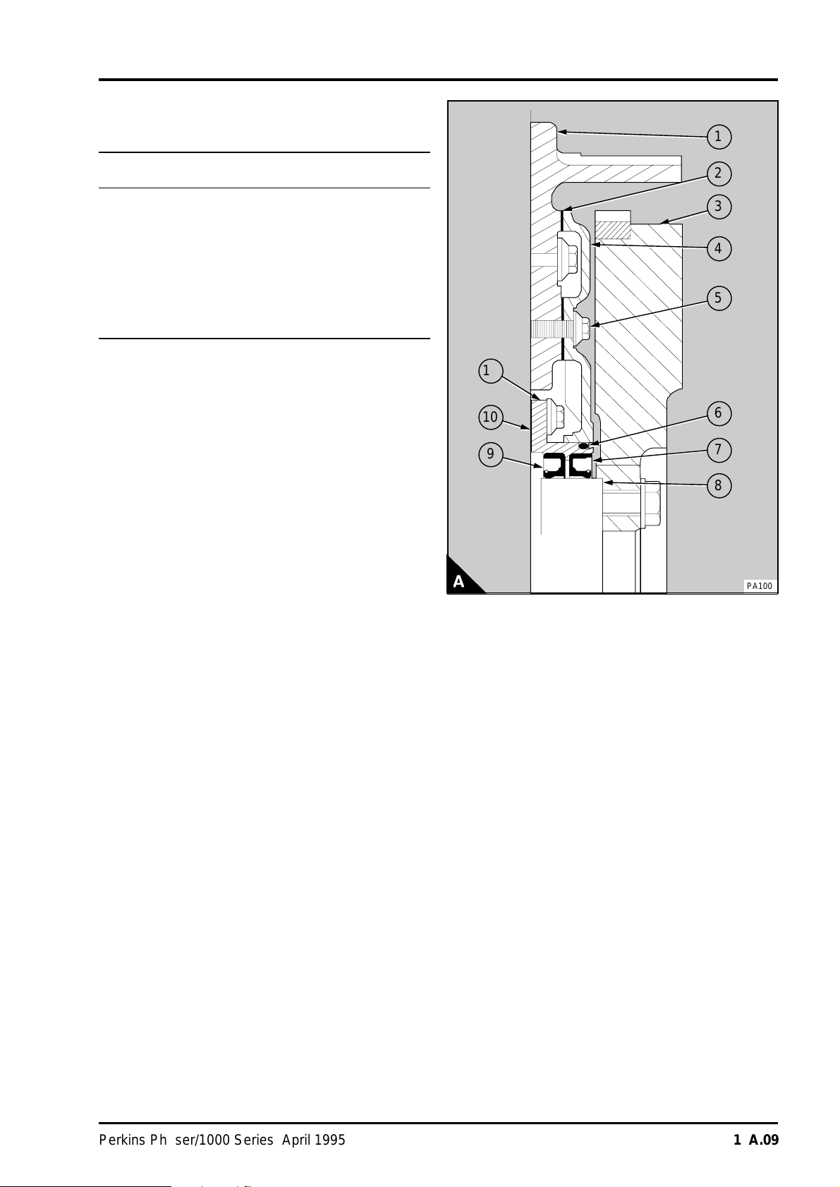
Rear oil seal assembly - engines which
aaa
aaa
aaa
aaa
aaa
aaa
aaa
aaa
aaa
aaa
aaa
aaa
aaa
aaa
aaa
aaa
aaa
aaa
aaa
aaa
aaa
aaa
aaa
aaa
aaa
aaa
aaa
aaa
aaa
aaa
aaa
aaa
a
a
a
a
a
a
a
aaa
a
a
a
a
a
have a flywheel housing that is oil filled
CRANKSHAFT ASSEMBLY 14
1
To remove and to fit14A-02B
Special tools:
Replacer tool for rear oil seal, PD.145D
Consumable products:
POWERPART Threadlock
POWERPART Silicone rubber sealant
This arrangement for the crankshaft rear oil seal is
for engines which have a flywheel housing that is
filled with oil. This arrangement uses two lip seals
which are narrower than the standard seal and are
fitted back to back on the crankshaft palm. The
front seal (A9) prevents leakage of oil from the
engine and the rear seal (A7) prevents leakage of
oil from the flywheel housing. A cover (A4) and joint
(A2) are used to prevent leakage of oil past the
setscrews which retain the flywheel housing (A1) to
the rear face of the cylinder block. An "O" ring (A6)
is used to seal between the cover and the seal
housing. Oil leakage past the "O" ring or one of the
oil seals will pass through a hole in the seal housing
between the two seals. The oil will then pass
through two cast grooves in the front face of the
flywheel housing. These grooves are in the
4 o'clock and 8 o'clock positions.
11
10
2
3
4
5
a
a
a
a
a
a
a
a
a
a
9
6
7
8
PA100
To remove
1 Release the setscrews which retain the flywheel
and remove the flywheel (A3).
2 Release the setscrews (A5) which retain the
cover (A4) and remove the cover. On later covers
their are two integral lugs to enable the use of a
lever to remove the cover. Remove the joint (A2)
and clean the joint faces of the cover and flywheel
housing.
3 Release the setscrews and the cap screws and
washers which retain the housing (A11) for the rear
oil seals and remove the housing. Clean the joint
faces of the seal housing and cylinder block.
Perkins Phaser/1000 Series, April 1995 14A.09
Page 76

14 CRANKSHAFT ASSEMBLY
To fit
1 Clean the crankshaft palm (14A.09/A8) and
check for wear in the seal location areas. If there is
wear, a "Speedi-Sleeve" (14A.13/A1), part number
21825188, can be fitted, see "To fit and remove a
"Speedi-Sleeve". If a "Speedi-Sleeve" is not
available the crankshaft palm can be machined to
give a minimum diameter of 133,17 mm (5.243 in).
Do not machine the last 2,5 mm (0.10 in) of the
crankshaft palm as this is necessary for flywheel
location. A "Speedi-Sleeve" must not be fitted if the
crankshaft palm has been machined undersize.
2 Ensure that the dowels for the oil seal housing
are fitted in the cylinder block. Put a new joint
(14A.09/A10) in position on the dowels, no jointing
compound is necessary.
3 Put the seal replacer tool, which is used for
standard seals, on the crankshaft palm. Lubricate
lightly the crankshaft palm, the seal replacer tool
and the lip of the seals with clean engine lubricating
oil.
4 Put the seal and housing assembly onto the seal
replacer tool and carefully push the assembly onto
the dowels. Remove the seal replacer tool, fit the
setscrews and the cap screws together with their
washers. Tighten the setscrews to 22 Nm (16 lbf ft)
2,2 kgf m and the cap screws to 13 Nm (10 lbf ft)
1,3 kgf m.
5 Fit a new "O" ring (14A.09/A6) in its recess in
the seal housing and lightly lubricate it with clean
engine oil.
6 Apply a suitable jointing compound to one side of
a new cover joint to hold the joint in position. Put
the joint in position on the flywheel housing. Put the
cover into position on the joint and fit the
setscrews. New setscrews have a sealant applied
by the manufacturer. If these setscrews are to be
used again, the threads of the setscrews and the
threads in the flywheel housing must be cleaned. A
suitable sealant, for example POWERPART
Threadlock, must then be applied to the setscrew
threads. Tighten the setscrews to 22 Nm (16 lbf ft)
2,2 kgf. m.
7 Ensure that the location faces of the flywheel
and crankshaft are clean and free from damage. Fit
the flywheel and the setscrews together with their
washers. Tighten the setscrews to 105 Nm
(77 lbf ft) 10,7 kgf m.
8 If the starter motor is removed from the engine,
clean the flange face of the starter motor and the
face of the flywheel housing. Apply a 2,0 mm
(0.080 in) continuous bead of POWERPART
Silicone rubber sealant to the flange face of the
starter motor near to the spigot before the starter
motor is fitted.
Caution: If the engine is to be operated before oil
is added to the flywheel housing, the rear oil seal
must not be fitted until after the engine has run.
14A.10 Perkins Phaser/1000 Series, April 1995
Page 77
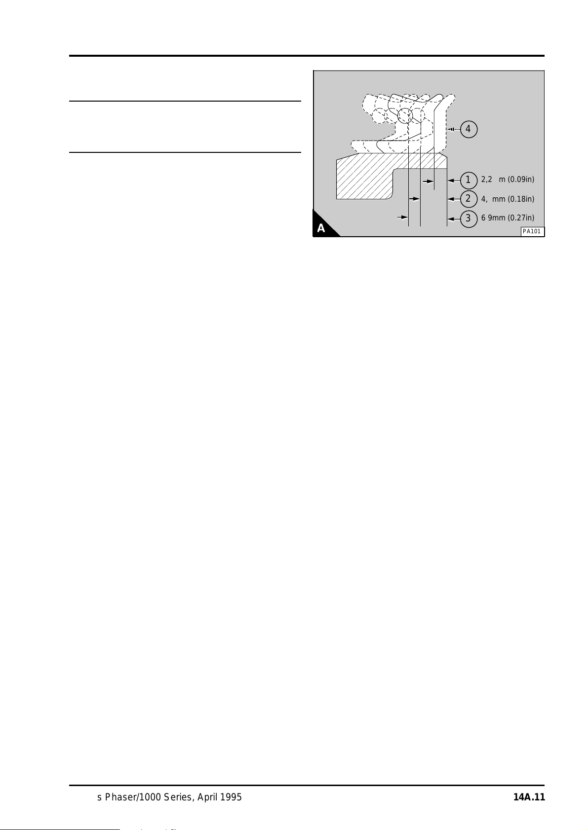
To renew the rear oil seal - engines which
aaa
aaa
aaa
aaa
aaa
aaa
aaa
aaa
aaa
aaa
aaa
aaa
aaaaaaaaaaaaaaa
a
a
a
aaaaaaaaaaaaaaa
a
a
a
a
a
aaaaaaaaaaaaaaa
a
a
a
a
a
have the standard seal14A-03A
Special tools:
Replacer tool for rear oil seal, PD.145D
There are four positions in which the seal can be
fitted in the housing (A).
Position "1" is used in the factory or if a new seal
is fitted on a new or reground crankshaft in service.
Position "2" is used when a new seal is fitted in
service and the crankshaft flange is worn in position
"1".
Position "3" is used when a new seal is fitted in
service and the crankshaft flange is worn in
positions "1" and "2".
Position "4" can also be used with a new seal in
service, if a wet clutch is not used and the
crankshaft is new or the crankshaft palm area has
been corrected. Ensure that the seal is fitted square
in the housing.
If all positions have been used it is permissible to
grind the crankshaft flange, see the data and
dimensions.
1 Remove the seal and housing assembly,
operation 14A-02.
2 Put the engine side of the housing on a suitable
support and press out the seal with a suitable
adaptor.
3 Lubricate the outer circumference of the seal and
the bore of the seal housing with clean engine
lubricating oil.
4 Put the engine side of the housing on a suitable
support and put the seal into position on the
flywheel end of the bore with the spring of the seal
towards the housing.
5 Press the seal into the housing to the correct
position with the relevant side of the tool
CRANKSHAFT ASSEMBLY 14
4
aaaaaaaaaaaaa
2,2mm (0.09in)
1
aaaaaaaaaaaaa
2
4,6mm (0.18in)
aaaaaaaaaaaaa
aaaaaaaaaaaaa
6,9mm (0.27in)
3
aaaaaaaaaaaaa
PA101
a
a
a
a
a
Perkins Phaser/1000 Series, April 1995 14A.11
Page 78
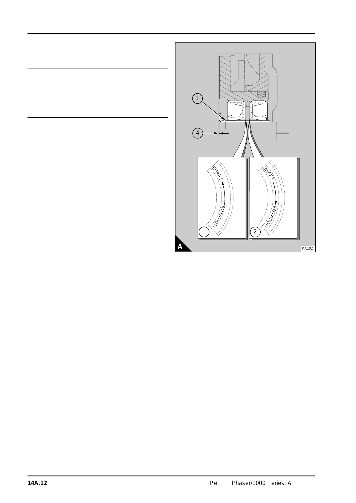
14 CRANKSHAFT ASSEMBLY
a
a
a
a
a
a
a
a
a
a
a
a
aaa
aaa
aaa
a
a
a
a
a
a
To renew the rear oil seals - engines
which have a flywheel housing that is oil
filled14A-03B
Consumable products:
POWERPART Threadlock
POWERPART Liquid gasket
POWERPART Silicone rubber sealant
1 Remove the seals from the housing with a
suitable lever. Ensure that the seal housing is not
damaged. Do not try to press the seals out of the
housing as there is a shoulder in the housing (A).
2 Clean thoroughly the oil seal housing. Inspect the
oil seals for damage. If only a small scratch can be
seen across the lip of the seal, do not fit the seal.
3 Before the oil seals are fitted into the housing
ensure that the correct seal is fitted to the correct
side of the housing. Each of the seals has an arrow
(A2) and (A3) on the flat face of the seal. This
arrow indicates the correct direction of shaft
rotation for the seal.
4 Lubricate lightly the outer circumference of the
front oil seal and the bore of the housing for the
front seal with clean engine oil.
5 With the flywheel side of the seal housing on a
suitable support, press the new front seal into the
housing. Use a suitable tool which will apply
pressure only to the flat inside face of the seal. Use
only enough pressure to ensure that the flat face of
the seal is against the shoulder in the housing. Too
much pressure could damage the shoulder.
6 Lubricate lightly the outer circumference of the
rear oil seal and the bore of the housing with clean
engine oil.
7 With the engine side of the seal housing on a
suitable support, carefully press the rear oil seal
onto the shoulder in the housing with the same tool
as for the front seal. Ensure that the seal is against
the shoulder in the housing.
Caution: The rear oil seal must not be fitted if the
engine is to be operated before the oil is added to
the flywheel housing. The seal must be fitted to the
seal housing after the engine has been run.
1
4
3
2
PA102
14A.12 Perkins Phaser/1000 Series, April 1995
Page 79
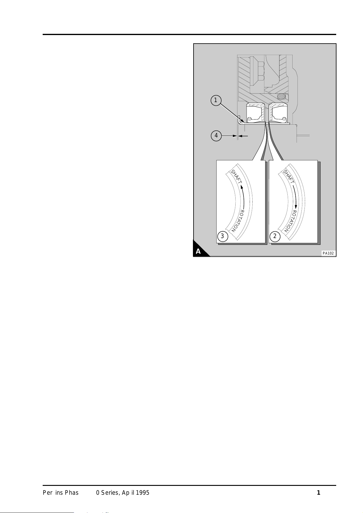
To fit and remove a "Speedi-Sleeve"
aaa
aaa
aaa
a
a
a
a
a
a
aaa
aaa
aaa
a
a
a
a
a
a
1 Clean the crankshaft palm and remove sharp
edges or rough areas from the crankshaft palm.
2 Ensure that the sleeve (A1) is clean. Apply a
narrow bead of POWERPART Liquid gasket around
the bore of the sleeve 5 mm (0.2 in) from the front
face of the flange. The sleeve must be fitted not
more than five minutes after the Liquid gasket has
been applied.
3 Ensure that the crankshaft is fully forward. Use a
suitable adaptor and a hammer to carefully drive the
sleeve onto the crankshaft palm. The sleeve must
be fitted with a clearance of 0,4/0,6 mm
(0.016/0.024 in) between the rear face of the
cylinder block and the front face of the sleeve
flange (A4). Ensure that this clearance is equal all
around the flange of the sleeve. Do not try to pull
the sleeve backwards as damage could occur to
the sleeve.
4 Fit a new joint for the oil seal assembly.
Lubricate lightly the sleeve and the lip of the oil
seals with clean engine oil and fit the assembly. Fit
a new joint to the flywheel housing and fit the
cover. Fit the flywheel.
5 To remove a sleeve, make a deep scratch with a
sharp scriber along the full length of the sleeve.
Insert the edge of a thin blade at the end of the
scratch mark. Turn the blade to make a split along
the scratch mark and pull the sleeve apart. If only
the flange is removed, a recommendation of the
sleeve manufacturer is to spread the sleeve. To do
this use a small hammer and a suitable punch with
a round end. Make one or more lines of small
distortions across the full width of the sleeve. This
should increase the diameter of the sleeve enough
to enable its removal.
CRANKSHAFT ASSEMBLY 14
1
4
3
2
PA102
Perkins Phaser/1000 Series, April 1995 14A.13
Page 80
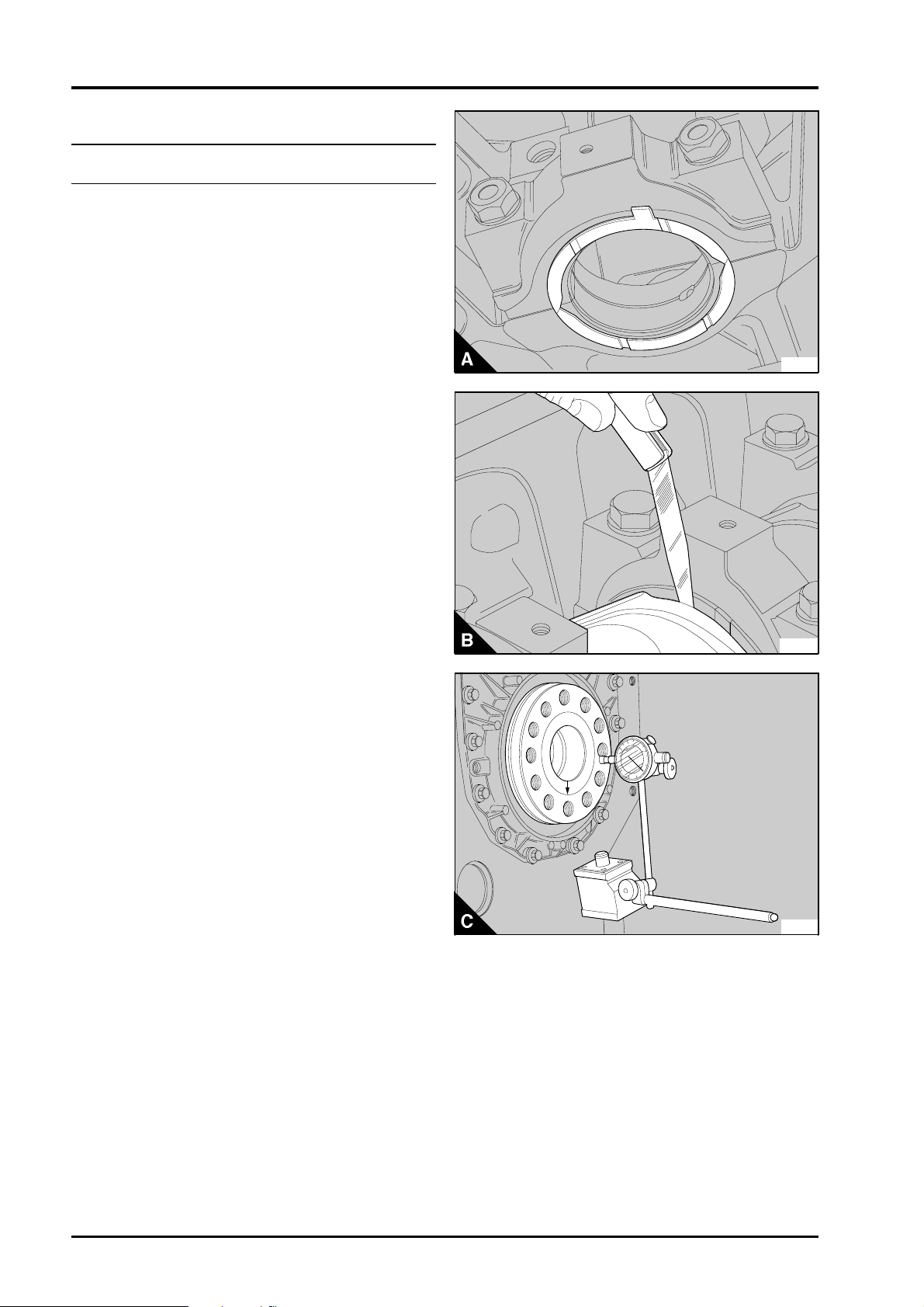
14 CRANKSHAFT ASSEMBLY
Thrust washers
To check crankshaft end-float14A-04
The axial movement of the crankshaft is controlled
by two half thrust washers fitted both sides of the
centre main bearing (A). The end-float can be
checked with a feeler gauge between a thrust
washer and the crankshaft (B), or with a dial test
indicator on one end of the crankshaft to check the
movement (C).
If the end-float is more than the tolerance given in
data and dimensions, thrust washers which are
0,019 mm (0.0075 in) oversize can be fitted.
The oversize thrust washers can be fitted to one or
to both sides of the main bearing. They are fitted
instead of the standard size washer, to reduce the
end-float to the factory tolerances.
PA103
PA104
PA105
14A.14 Perkins Phaser/1000 Series, April 1995
Page 81
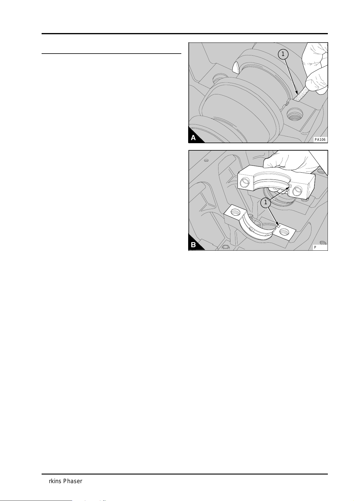
To remove and to fit14A-05
a
a
a
a
a
a
aaa
aaa
aaa
To remove
1 Drain the lubricating oil and remove the
lubricating oil sump, operation 19A-03.
2If necessary, remove the balancer unit, operation
14A-10.
3 If necessary, remove the lubricating oil strainer
and suction pipe, operation 19A-04.
4 Release the setscrews of the centre main
bearing and remove the main bearing cap complete
with the lower half thrust washers.
5 Press down one end of each upper half thrust
washer, with a suitable tool made of a soft material
(A1), to slide the washer from its recess. Where
necessary, move the crankshaft to the front or to
the rear to loosen a tight washer.
To fit
CRANKSHAFT ASSEMBLY 14
1
PA106
1 Lubricate the thrust washers with clean engine
lubricating oil.
2 Slide the upper half thrust washers into their
recesses in the cylinder block. Ensure that the
sides of the thrust washers which have the grooves
are against the crankshaft.
3 Fit the lower half thrust washers to the main
bearing cap with the location tags in their recesses.
4 Ensure that the location thimbles are fitted
correctly in the main bearing cap or in the cylinder
block.
5 Ensure that the bearing is fitted correctly in the
cap and that the the bearing and the crankshaft
journal are clean. Lubricate the bearing with clean
engine lubricating oil.
6 Fit the cap with the location tags of both half of
the shell bearings to the same side (B1). Tighten
the main bearing setscrews gradually and evenly to
265 Nm (196 lbf ft) 27,0 kgf m for six cylinder
engines. 250 Nm (185 lbf ft) 26,0 kgf m for four
cylinder engines.
7Check the crankshaft end-float, operation
14A-04.
8If necessary, fit the balancer unit, operation
14A-10.
9 If necessary, fit the lubricating oil strainer and the
suction pipe, operation 19A-04.
10Fit the lubricating oil sump, operation 19A-03,
and fill it to the correct level with an approved
lubricating oil.
1
PA107
Perkins Phaser/1000 Series, April 1995 14A.15
Page 82

14 CRANKSHAFT ASSEMBLY
Main bearings
To remove and to fit (with the crankshaft in position)14A-06
If the rear main bearing is to be removed with the
crankshaft in position, the flywheel, the flywheel
housing, the rear oil seal housing and the bridge
piece will have to be removed.
Except for engines with a balancer unit fitted, the
front main bearing can only be removed if a suitable
spanner is available that will enable the torque to be
applied correctly to the setscrews of the main
bearing cap. If a suitable spanner is available, the
front main bearing cap can be removed together
with the oil pump. For six cylinder engines, it will be
necessary to remove the suction pipe and strainer
and the delivery pipe. For four cylinder engines,
either the balancer unit or the suction pipe and
strainer, the delivery pipe and the relief valve will
have to be removed.
To remove
1 Drain the lubricating oil and remove the sump,
operation 19A-03.
2 Remove all necessary components to get access
to the specific bearing cap.
3 Release the setscrews of the bearing cap and
remove the bearing cap. Remove the lower half of
the shell bearing from the cap.
4 With a suitable tool, push the upper half of the
shell bearing from the side opposite to the location
tag to remove the bearing tag from its recess in the
bearing housing. Carefully rotate the crankshaft to
release the bearing from its housing. Keep the
bearing halves in their relevant positions.
14A.16 Perkins Phaser/1000 Series, April 1995
Page 83
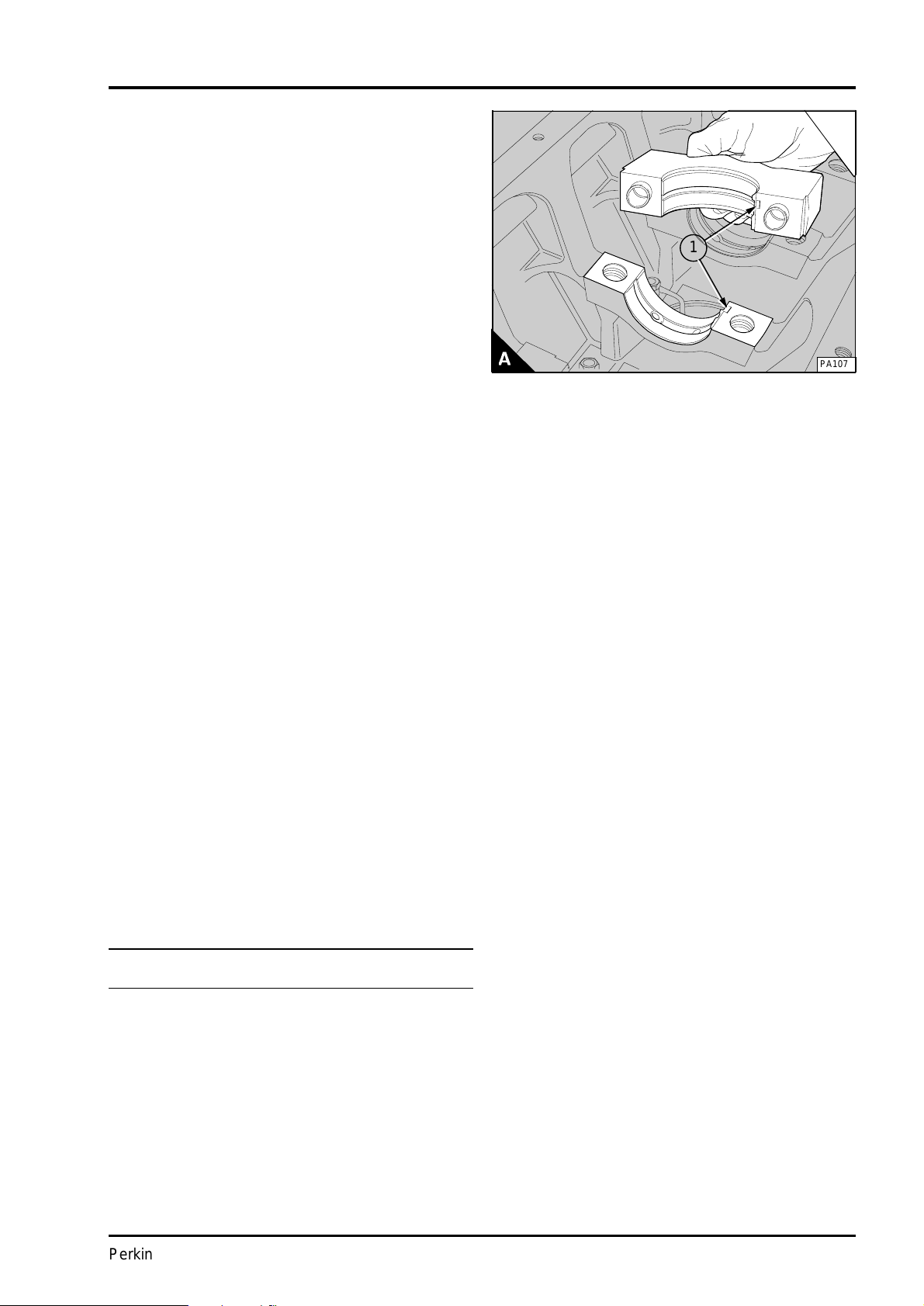
To fit
aaa
aaa
aaa
1 Clean the upper half of the shell bearing and
lubricate the bearing surface with clean engine
lubricating oil.
Caution: Only the upper half of the bearing has
lubrication holes and must be fitted to the side of
the cylinder block.
2 Fit the plain end of the upper half of the bearing
between the crankshaft journal and the side of the
bearing housing which has the recess for the
location tag. Slide the bearing into its housing until
the tag on the bearing is fitted correctly in its
recess in the housing.
3 Clean the lower half of the bearing and cap,
lubricate the bearing surface with clean engine
lubricating oil.
4 Fit the bearing into the cap with the tag of the
bearing fitted correctly in the recess in the cap.
5 Ensure that the location thimbles are fitted
correctly to the cap or to the cylinder block. Fit the
bearing cap with the location tags of both bearings
on the same side (A1).
6 Inspect the setscrews for damage and for
distortion and renew them if necessary. Lightly
lubricate the setscrew threads with clean engine
lubricating oil. Fit the setscrews and the washers
and tighten the setscrews gradually and evenly to
265 Nm (196 lbf ft) 27,0 kgf m for six cylinder
engines and 250 Nm (185 lb ft) 26,0 Kgf m for four
cylinder engines.
Note: Washers are not fitted between the
setscrews and the bearing caps on the latest
engines.
7 Ensure that the crankshaft turns freely. If the
thrust washers have been removed and fitted,
check the crankshaft end-float, operation 14A-03.
8 Fit all the components which were removed for
access to the main bearing cap.
9Fit the lubricating oil sump, operation 19A-03 and
fill it to the correct level with an approved
lubricating oil.
CRANKSHAFT ASSEMBLY 14
1
PA107
To inspect14A-07
Inspect the bearings for wear and for other damage.
If a bearing is worn or damaged, renew both half of
the shell bearings and check the condition of the
other bearings.
Perkins Phaser/1000 Series, April 1995 14A.17
Page 84

14 CRANKSHAFT ASSEMBLY
Crankshaft
To remove and to fit14A-08
Consumable products:
POWERPART Silicone rubber sealant
POWERPART liquid gasket
Warning! Use lift equipment or obtain assistance to
lift heavy engine components such as the balancer
unit, flywheel housing, crankshaft and flywheel.
To remove
1 Before the engine is removed from the vehicle or
from the machine, drain the lubricating oil and the
coolant.
2Remove the lubricating oil sump, operation
19A-03.
3 Remove the fan, the drive belts, the fan drive
pulley and housing and the coolant pump, see
section 21.
4Remove the crankshaft pulley, operation
14A-01A or 14A.01B.
5 Remove the alternator and its mounting bracket,
see section 23.
6 Remove the compressor and its drive assembly
or remove the exhauster, see section 24.
7Remove the timing case cover, operation
15A-01.
8Remove the fuel injection pump, see section 20.
9 Remove the timing gears and the timing case,
see section 15.
10 Remove the flywheel and the flywheel housing,
see section 22.
11Remove the rear oil seal housing, operation
14A-02A or 14A.02B.
12If a balancer unit is fitted, remove it, operation
14A-10. If a balancer unit is not fitted, remove the
lubricating oil suction pipe and strainer, the
lubricating oil pump, the delivery pipe and the relief
valve (four cylinder engines) and the lubricating oil
crossover pipe, if fitted, see section 19.
13 Remove the bridge piece and the rubber seals.
Later engines may not have rubber seals fitted.
14 Remove the caps of the connecting rods. Keep
the bearings and caps together. Remove the bolts
of the connecting rods and carefully push the
pistons into their bores.
14A.18 Perkins Phaser/1000 Series, April 1995
Page 85

15 Ensure that the tops of the main bearing caps
are stamped with their relevant position number.
Remove the main bearing caps, the lower half of
the shell bearings and the upper and lower thrust
washers. Keep the bearings with their relevant
caps.
16 Lift out the crankshaft. Remove the upper half
of the bearings and keep each bearing with its
relevant lower half and cap.
To fit
1 Ensure that all lubricating oil passages are clean
and free from restriction.
2 Clean the main bearing housings and the upper
half of the bearings. Fit the shell bearings with the
location tags fitted correctly in their recesses.
Lubricate the bearings with clean engine lubricating
oil.
3 Ensure that the main journals of the crankshaft
are clean. Put the crankshaft in position on the
upper bearings.
4 Clean and lubricate the upper half thrust washers
and slide them into their recesses on both sides of
the bearing housing. Ensure that the slotted sides
of the thrust washers are towards the crankshaft.
5 Clean the bearing caps and the lower half of the
bearings. Fit the bearings to the caps with the
location tags fitted correctly in their recesses.
Lubricate the bearings with clean engine lubricating
oil.
6 Clean the lower half thrust washers and lubricate
them with clean engine lubricating oil. Fit the thrust
washers on both sides of the bearing cap for the
centre main bearing.
7 Check that the location thimbles for the main
bearing caps are fitted correctly in the caps or in
the cylinder block. Fit the bearing caps in their
correct positions (as shown by the position number
stamped on the top of the cap) with the location
tags of the bearings on the same side. In this
position the serial numbers stamped on the bearing
caps will be in line. The serial number stamped on
the bearing caps must be the same as the number
stamped on the bottom face of the cylinder block.
The third and fifth bearing caps of six cylinder
engines are not stamped with a serial number.
CRANKSHAFT ASSEMBLY 14
Perkins Phaser/1000 Series, April 1995 14A.19
Page 86
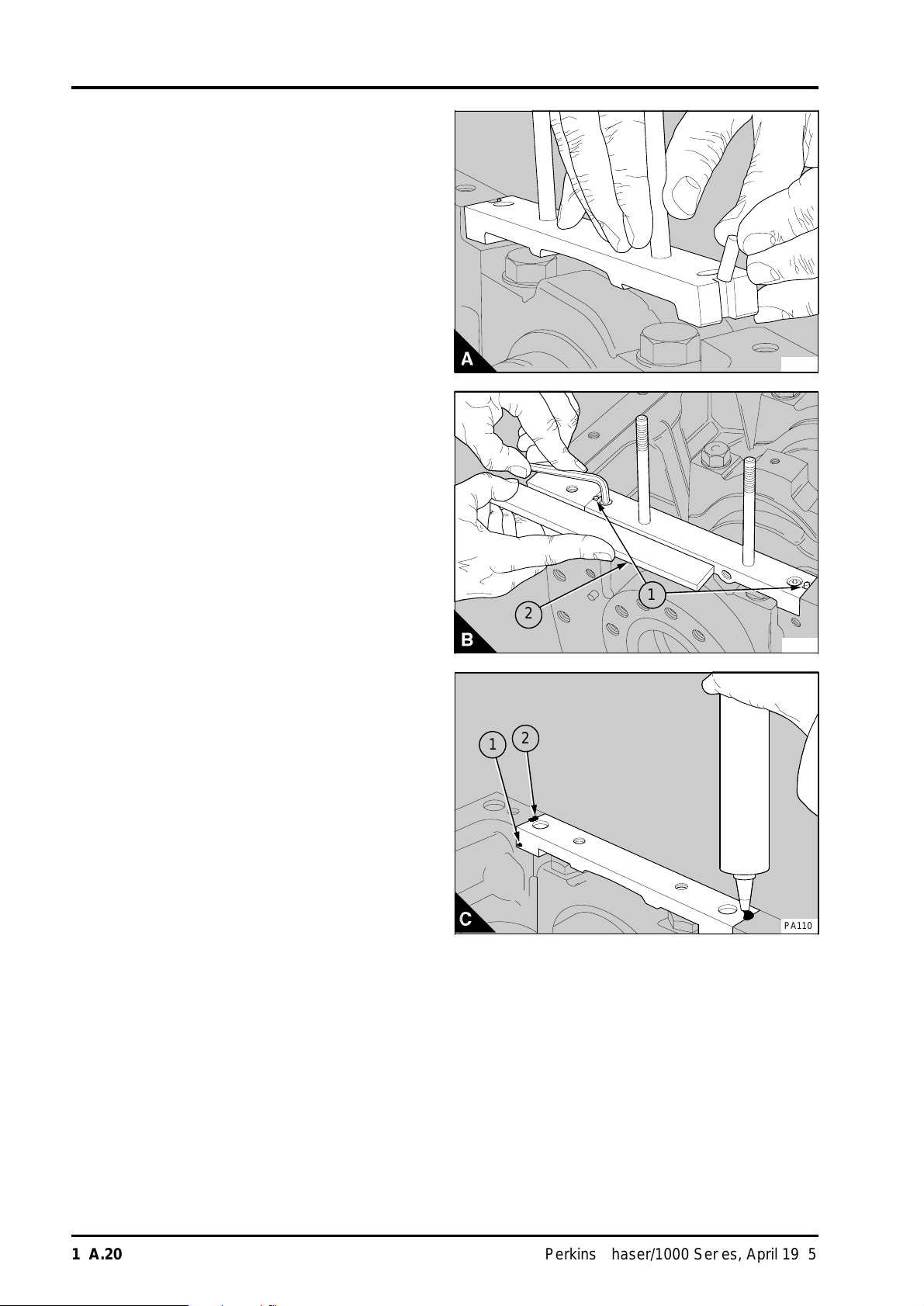
14 CRANKSHAFT ASSEMBLY
a
a
a
a
a
a
aaa
aaa
aaa
aaa
a
a
a
a
a
a
aaa
aaa
aaa
a
a
8 Fit the setscrews and the washers to the main
bearing caps and tighten the setscrews gradually
and evenly to 265 Nm (196 lbf ft) 27,0 kgf m for six
cylinder engines and 250 Nm (185 lb ft) 26,0 kgf m
for four cylinder engines.
Note: Washers are not fitted between the
setscrews and the bearing caps on the latest
engines.
9 For early engines fitted with rubber seals: Clean
the bridge piece and the location areas for the
bridge piece in the cylinder block. Apply a narrow
strip of POWERPART silicone rubber sealant in the
corners and around the thread holes of the bridge
piece seat in the cylinder block. Fit the bridge piece
and the two rubber seals (A). The rubber seals will
be a little higher than the bridge piece when they
are fitted correctly. Use a straight edge (B2) to
ensure that the bridge piece is in line with the rear
face of the cylinder block. Tighten the bridge piece
cap screws (B1) to 16 Nm (12 lbf ft) 1,6 kgf m.
For later engines fitted with POWERPART liquid
gasket: A bridge piece has been introduced which
uses POWERPART liquid gasket instead of the
rubber seal in the groove at each end of the bridge
piece. The groove at each end of the new bridge
piece is cast and is off-centre. The procedure to fit
the new bridge piece is the same as for the earlier
bridge piece, except for the instructions given
below. Apply a 1/8 in (3.0 mm) bead of
POWERPART liquid gasket along the corner in the
top of the recess in the cylinder block for the bridge
piece.
When the bridge piece is in position and the cap
screws have been tightened, inject POWERPART
liquid gasket into the groove (C2) at each end of
the bridge piece. Continue to inject sealant until the
groove is completely full and the sealant leaves the
lower groove (C1) at the front and rear of the bridge
piece.
It may be necessary to stop the sealant at one side
of the lower groove in order to ensure it will flow
from the opposite side of the groove.
PA108
1
2
PA109
2
1
PA110
14A.20 Perkins Phaser/1000 Series, April 1995
Page 87

CRANKSHAFT ASSEMBLY 14
Caution: When the sump joint is removed, damage
can occur to the seal in the grooves of the bridge
piece. If the seal is damaged, apply enough sealant
to completely fill the grooves.
Note: Most of the latest engines have setscrews in
place of studs to fasten the sump to the bridge
piece. The threads of the setscrews have a sealant
applied by the manufacturer. When the setscrews
are to be used again, ensure that the threads of the
setscrews and of the bridge piece are clean and a
sealant is applied to the threads of the setscrews.
These instructions also apply to studs.
10 Fit the connecting rod caps, operation 13A-01.
Rotate the crankshaft two turns to ensure free
movement.
11If necessary, fit the balancer unit, operation
14A-10. If a balancer unit is not used, fit the
lubricating oil pump, the lubricating oil suction pipe
and strainer, the delivery pipe and the relief valve
(four cylinder engines) and if necessary, the
lubricating oil crossover pipe, see section 19.
12Fit the rear oil seal housing, operation 14A-02A
or 14A-02B.
13 Fit the flywheel housing and the flywheel, see
section 22.
14 Fit the timing case and the timing gears, see
section 15.
15Fit the fuel injection pump, see section 20.
16Fit the timing case cover, operation 15A-01.
17 Fit the compressor and its drive assembly or fit
the exhauster, see section 24.
18 Fit the alternator and its mounting bracket, see
section 23.
19Fit the crankshaft pulley, operation 14A-01A or
14A-01B.
20 Fit the coolant pump, the fan drive pulley and
housing, the drive belts and the fan , see section
21.
21Fit the lubricating oil sump, operation 19A-03.
22 After the engine has been installed, fill the
lubricating oil sump to the correct level with an
approved oil. Fill the cooling system.
To inspect14A-09
Check the crankshaft for wear and other damage.
The maximum permissible wear and ovality on the
crankshaft journals and crank pins is 0,04 mm
(0.0016 in).
The main journals and the crank pins of standard
size crank shafts can be machined to 0,25mm
(0.010 in), 0,50mm (0.020 in) or 0,75 mm (0.030 in)
undersize on diameter, see the data and
dimensions. Special undersize bearings are
available.
If the seal has been used in all of the service
positions, the crankshaft palm can be machined to
remove the wear marks. Further information can be
found in the data and dimensions.
Perkins Phaser/1000 Series, April 1995 14A.21
Page 88
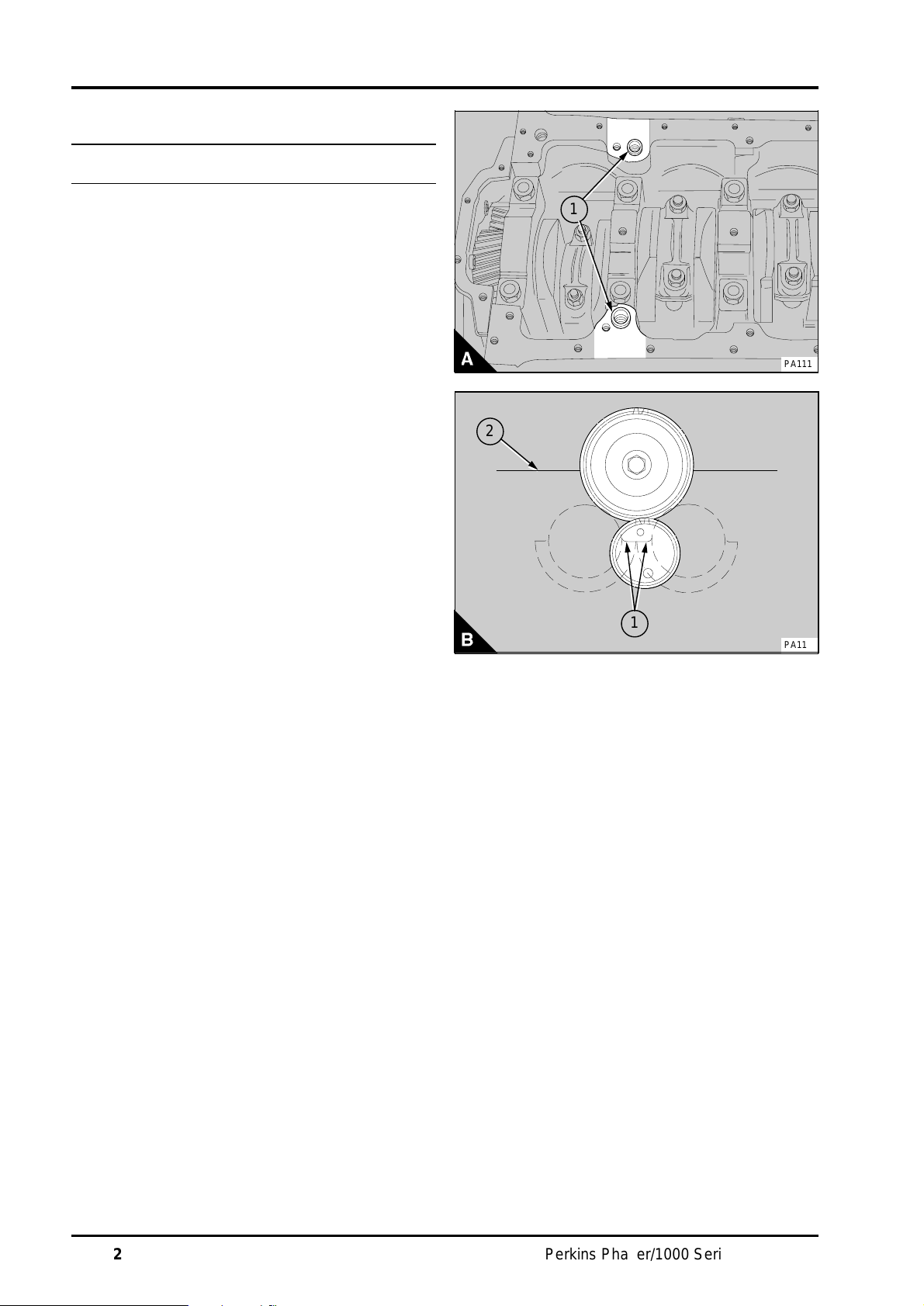
14 CRANKSHAFT ASSEMBLY
aaa
aaa
aaa
aaa
aaa
aaa
aaa
aaa
aaa
Balancer unit To remove and to fit14A-10
To remove
1 Drain the lubricating oil from the sump and
remove the sump, operation 19A-03.
Warning! The weight of the unit is approximately
25 kg (55 lb).
2 Provide a support for the balancer unit before
release of the setscrews from the engine.
3 Release the setscrews and lower carefully the
balancer unit. Make a note of the positions of the
setscrews of different lengths.
To fit
1 Ensure that the contact faces of the cylinder
block and of the balancer unit are clean and that
the two thimbles (A1) are fitted correctly to the
cylinder block.
2 Set the piston of number 1 cylinder to TDC,
operation 17A-01.
3 Before the balancer unit is fitted, ensure that the
flat faces of the balance weights are level with each
other (B1) and the weights hang down away from
the cylinder block (B2). The timing of the balance
weights to the drive shaft is correct when the large
hole and small hole in the front of the drive shaft
gear are in the positions shown in the illustration
(B).
Note: If the gear position shown in (B) cannot be
obtained, then the balancer must be partially
dismantled and the timing corrected (14A.26/A).
4 Fit the balancer unit to the cylinder block with the
correct screws in the centre positions of the
balancer frame. Ensure, when the idler and
crankshaft gears are in mesh, that the flat faces of
the balance weight are level with each other and
that they are towards the cylinder block. Check that
the balancer unit is fitted correctly on the thimbles
and fit the remainder of the setscrews in their
correct position. Tighten the setscrews to 54 Nm
(40 lbf ft) 5,5 kgf m.
5 Rotate the crankshaft through two turns to
ensure that it is free to rotate.
6Fit the lubricating oil sump, operation 19A-03 and
fill the sump to the correct level with an approved
oil.
1
PA111
2
1
PA112
14A.22 Perkins Phaser/1000 Series, April 1995
Page 89
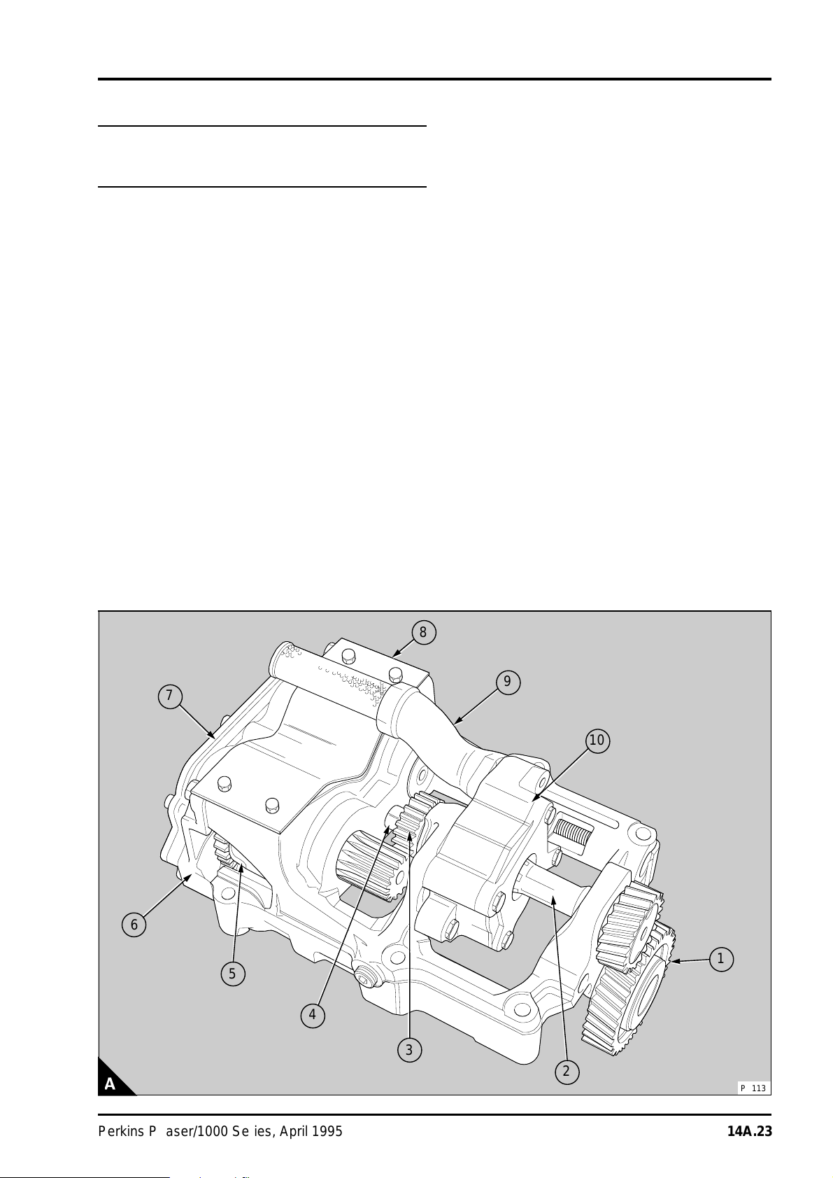
CRANKSHAFT ASSEMBLY 14
aaa
aaa
aaa
aaa
aaa
aaa
aaa
aaa
aaa
a
a
a
a
a
a
a
a
aaa
aaa
aaa
a
a
a
a
a
a
aaa
aaa
aaa
aaa
a
a
a
a
a
aaa
aaa
aaa
aaa
aaa
aaa
To dismantle and to assemble14A-11
Consumable products:
POWERPART Nutlock
To dismantle
1 Remove the balance weight cover (A8).
2 Release the setscrew and remove the idler gear
assembly (A1). Keep the components together as
an assembly to protect the needle roller bearing.
3 Prevent movement of the drive shaft (A2) and
loosen the nut (A4) of the drive gear for the balance
weights (A3). Put a suitable flat distance piece in
position between the nut and the balancer frame.
Turn the nut until it is against the face of the
distance piece. Continue to turn the nut with a
suitable spanner until the Loctite seal on the splines
of the drive shaft is broken and the gear is loose on
the shaft. Remove the nut and the drive gear and
remove the drive shaft. Ensure that the needle
roller bearings are not damaged when the drive
shaft is removed.
4 Release the setscrews which hold the lubricating
oil pump and the suction pipe (A10 and A9) to the
balancer frame and remove the lubricating oil pump
and the suction pipe.
5 Release the setscrews and remove the transfer
plate and joint for the lubricating oil (A7) from the
rear of the balancer unit. Make a note of the
position of the direction arrows on the outside of
the transfer plate (14A.26/B or C) to ensure that it
can be assembled correctly .
8
9
7
a
a
a
a
10
6
1
5
4
3
2
PA113
Perkins Phaser/1000 Series, April 1995 14A.23
Page 90

14 CRANKSHAFT ASSEMBLY
Notes:
• The latest oil transfer plate is fitted without a joint
or sealant; always give the correct engine number
when parts are needed.
• There are two plugs in the balancer frame, a
short tapered plug with a hexagonal socket head
and a long plug with a square socket head. These
plugs control the flow of oil through the balancer
frame. The position of the plugs is decided by
which side of the engine the filter is fitted. When
the filter is fitted on the left side, the short plug is
fitted in the side of the balancer and the long plug
is fitted in the bottom (14A.26/B). When the filter is
fitted on the right side of the engine, the short plug
is fitted in the bottom of the balancer and the long
plug is fitted in the side (14A.26/C).
Caution: Removal of these plugs can cause
damage to the threads in the balancer frame and a
new balancer frame will be needed. When a
balancer unit is to be fitted, ensure that the
lubricating oil flow through the balancer frame is
correct for the position of the lubricating oil filter.
6 Release the setscrews and remove the rear
cover of the balancer frame (14A.23/A6). A hammer
and a suitable drift will be necessary to remove the
rear cover from the dowels.
7 Remove the balance weights (14A.23/A5).
Ensure that the gear of the driven weight does not
damage the bush in the balancer frame.
8 Dismantle the lubricating oil relief valve,
operation 19A-09.
9 Clean the lubricating oil passages with an
approved kerosene cleaning solution and dry them
with low pressure compressed air.
14A.24 Perkins Phaser/1000 Series, April 1995
Page 91
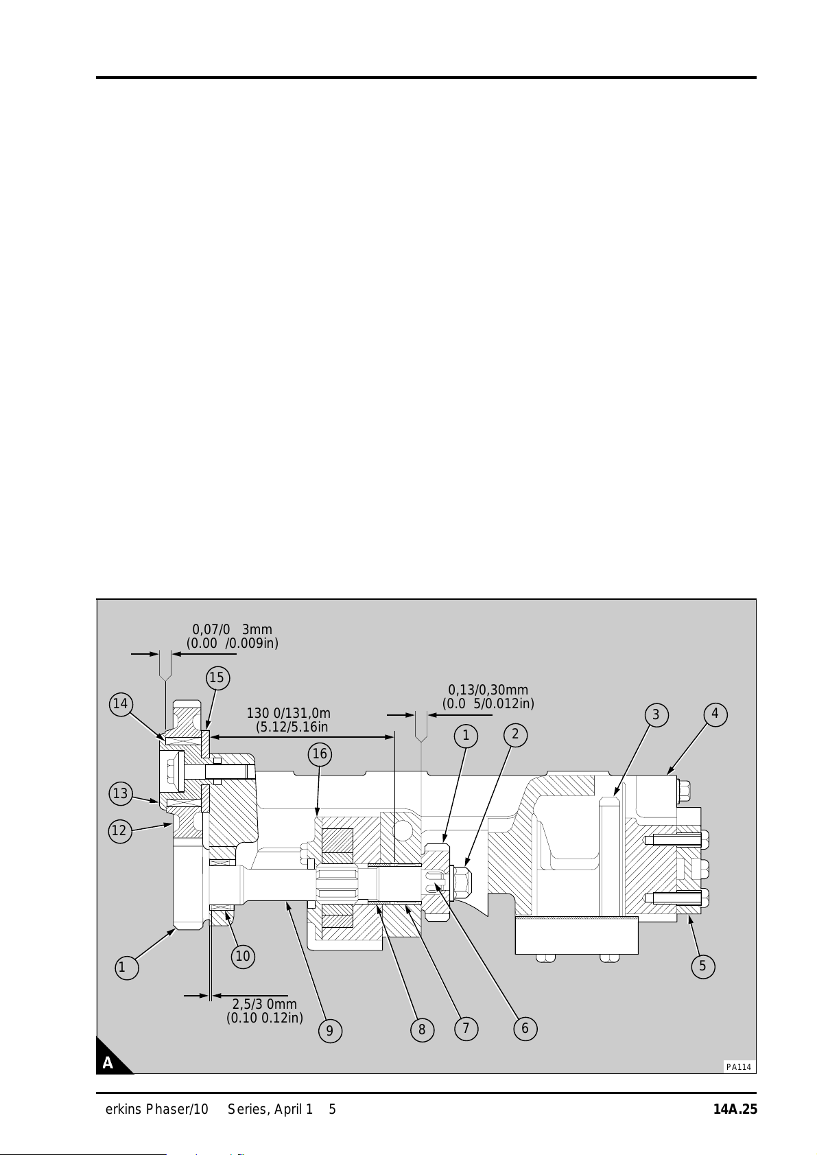
CRANKSHAFT ASSEMBLY 14
aaa
aaa
aaa
aaa
a
a
a
a
a
a
a
a
a
a
a
aaa
aaa
aaa
a
a
a
a
a
a
aaa
aaa
aaa
aaa
aaa
aaa
aaa
aaa
aaa
aaa
aaa
a
a
a
a
a
a
aaa
aaa
aaa
aaa
a
a
a
a
a
aaa
a
a
a
a
a
aaa
a
a
a
a
a
aaa
a
a
a
a
a
aaa
a
a
a
a
a
aaa
a
a
a
a
a
a
a
aaaaaaaaaaaaaaaaaaa
a
a
a
a
a
a
a
a
aaaaaaaaaaaaaaaaaaa
a
a
a
a
a
a
a
a
a
aaaaaaaaaaaaaaaaaaa
a
a
a
a
a
a
a
a
aaaaaaaaaaaaaaa
a
a
a
a
a
a
a
a
a
a
a
To assemble
1 Ensure that the location thimble (A8) in the rear
of the lubricating oil pump is 5,6/6,4 mm
(0.220/0.252 in) above the rear face of the pump.
Clean the contact faces of the lubricating oil pump
and the balancer frame. Fit the lubricating oil pump
(A16) to the balancer frame and tighten the
setscrews to 27 Nm (20 lbf ft) 2,8 kgf m.
Note: The latest balancers do not have a thimble
for the oil pump location. The location of the latest
oil pump is by a spigot on the rear face of the
pump.
2Assemble the lubricating oil relief valve, operation
19A-09.
3 Lubricate the needle roller bearings (A7 and A10)
with clean engine lubricating oil. Fit the drive shaft
(A9) and engage the splines for the lubricating oil
pump with the pump rotor. Ensure that the needle
roller bearing at the front of the balancer frame is
not damaged by the splines on the drive shaft.
4 Clean and dry the splines (A6) and the thread on
the end of the drive shaft. Apply a small amount of
Loctite Nutlock to the splines and to the thread. Fit
the drive gear of the balance weights (A1) with the
flat face of the gear towards the rear of the
balancer unit. Fit and tighten the nut (A2) to 82 Nm
(60 lbf ft) 8,4 kgf m. To tighten the nut, a peg
spanner must be made to fit into the two holes in
the front of the drive shaft and be suitable for use
with a torque wrench. Fit the peg spanner to the
front of the drive shaft. Hold the nut with a suitable
spanner and apply the torque to the peg spanner.
5 Ensure that the drive shaft turns freely. Check
the end-float of the drive shaft with feeler gauges
between the front face of the drive gear for the
balance weights and the frame (A).
14
13
12
a
a
a
a
a
a
11
aaaaaaaaaaaaaaaaa
0,07/0,23mm
aaaaaaaaaaaaaaaaa
aaaaaaaaaaaaaaaaa
aaaaaaaaaaaaaaaaa
(0.003/0.009in)
a
a
15
a
a
a
a
a
a
a
a
a
a
a
a
aaaaaaaaaaaaaaaaa
130,0/131,0mm
aaaaaaaaaaaaaaaaa
aaaaaaaaaaaaaaaaa
aaaaaaaaaaaaaaaaa
(5.12/5.16in)
a
a
10
a
a
aaaaaaaaaaaaa
2,5/3,0mm
aaaaaaaaaaaaa
aaaaaaaaaaaaa
aaaaaaaaaaaaa
(0.10/0.12in)
aaaaaaaaaaaaa
a
a
a
a
a
a
a
a
16
a
a
a
a
a
a
a
9
aaaaaaaaaaaaaaaaa
0,13/0,30mm
aaaaaaaaaaaaaaaaa
aaaaaaaaaaaaaaaaa
(0.005/0.012in)
aaaaaaaaaaaaaaaaa
1
8
7
3
4
2
5
6
PA114
Perkins Phaser/1000 Series, April 1995 14A.25
Page 92
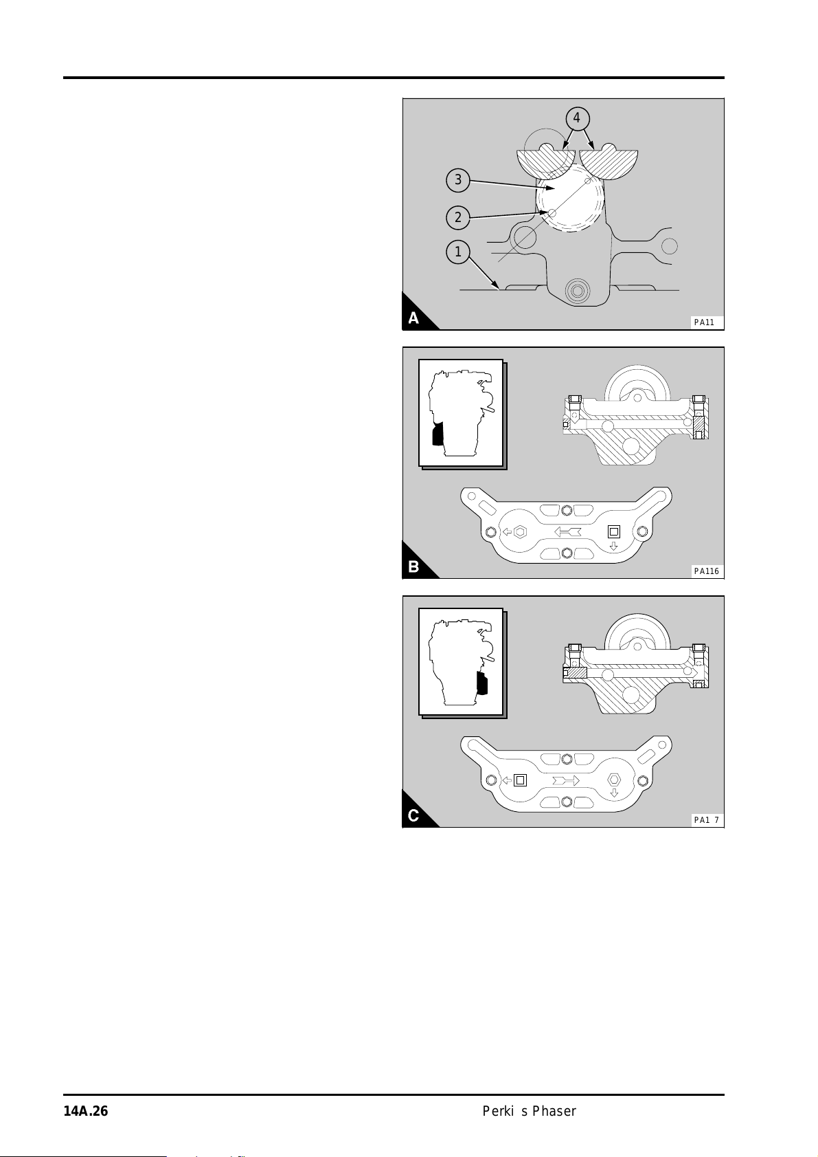
14 CRANKSHAFT ASSEMBLY
a
a
a
a
a
a
a
a
a
a
a
a
aaa
aaa
aaa
a
a
a
a
a
a
6 Put the balancer frame upside down on the
bench (A1). Turn the gear of the drive shaft (A3)
until the larger of the two outer holes (A2) - in the
front face of the drive gear - is in the position
shown in (A). Ensure that the drive shaft will not
move from this position. Lubricate the bushes in the
rear of the balancer frame with clean engine
lubricating oil and fit the balance weights in the
position shown in figure A. Ensure that the flats on
the balance weights are level with each other (A4).
With the balance weights in the correct position,
check that the drive shaft is still in the correct
position.
7 Fit the two dowels to the rear face of the
balancer frame. Lubricate the bushes in the rear
cover of the balance frame with clean engine
lubricating oil. Put the rear cover (14A.24/A4) in
position with the rear spigots of the balance weights
in the bushes of the cover. Hit lightly the rear cover
with a soft face hammer to fit the cover onto the
dowels. Fit the cover setscrews and tighten them to
54 Nm (40 lbf ft) 5,5 kgf m. Check the end-float of
the balance weights with feeler gauges between the
rear face of the balance weights and the front face
of the rear cover (14A.30/B). The correct end-float
is given in the data and dimensions. Check the
backlash between the drive gear of the balance
weights and the driven gear on the balance weight.
The correct backlash is given in the data and
dimensions.
8 Fit the oil transfer plate and the joint, if fitted, to
the rear of the rear cover and tighten the setscrews
to 30 Nm (22 lbf ft) 3,1 kgf m. Ensure that the plate
is fitted correctly for the oil filter position. The
direction arrow (B or C) indicates the direction of
lubricating oil flow for left side (B) and right side (C)
oil filter positions. The symbols and arrows (B or C)
indicate the position of the plugs in the balancer
frame and the shape of their socket heads. Ensure
that the plug on the bottom face of the frame is just
below the face. If a new frame and plugs are used,
ensure that the plugs are fitted correctly for the oil
filter position and the symbols on the oil transfer
plate.
4
3
2
1
PA115
PA116
PA117
14A.26 Perkins Phaser/1000 Series, April 1995
Page 93
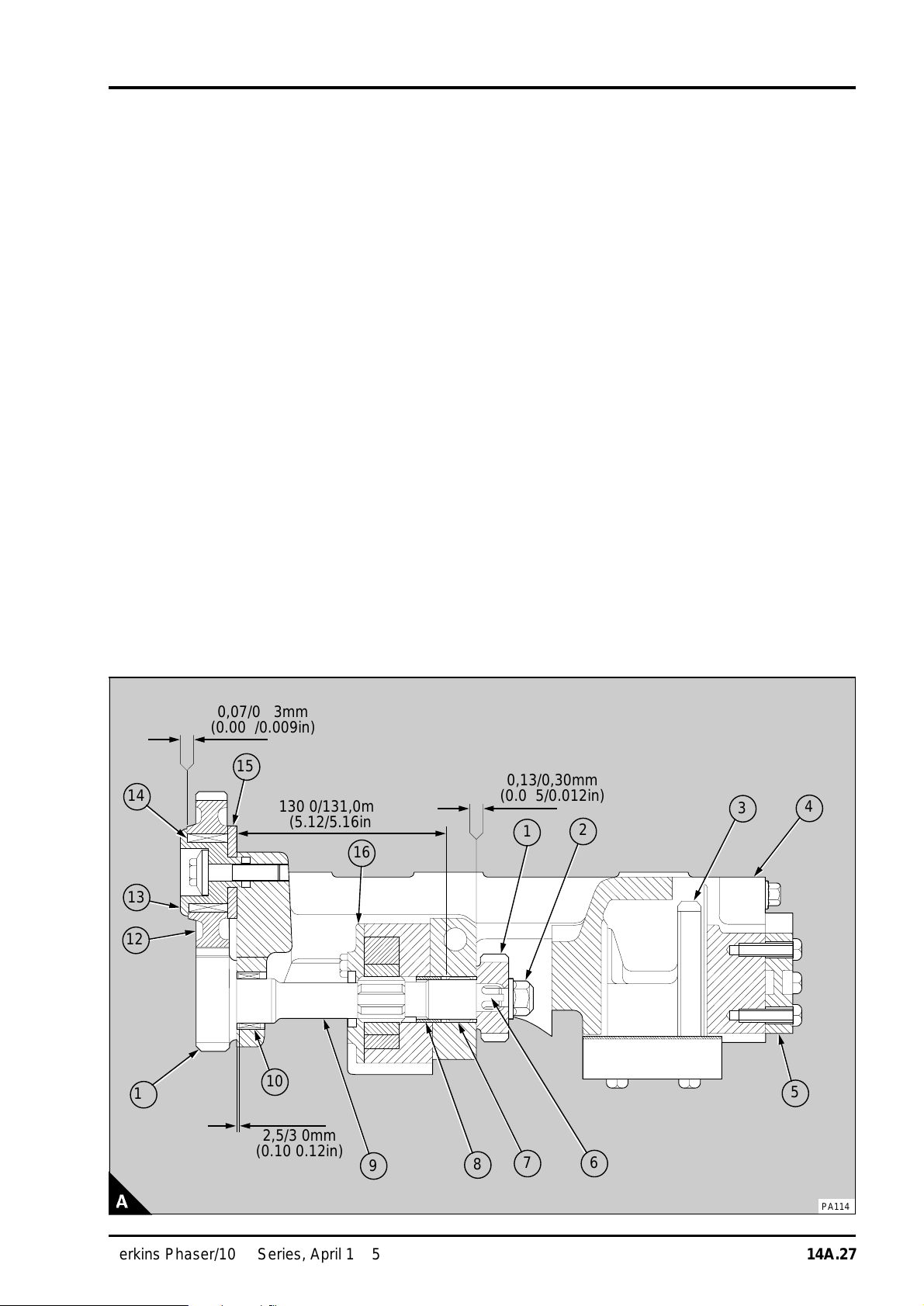
9 If necessary, press a new bearing (A14) into the
aaa
aaa
aaa
aaa
a
a
a
a
a
a
a
a
a
a
a
aaa
aaa
aaa
a
a
a
a
a
a
aaa
aaa
aaa
aaa
aaa
aaa
aaa
aaa
aaa
aaa
aaa
a
a
a
a
a
a
aaa
aaa
aaa
aaa
a
a
a
a
a
aaa
a
a
a
a
a
aaa
a
a
a
a
a
aaa
a
a
a
a
a
aaa
a
a
a
a
a
aaa
a
a
a
a
a
a
a
aaaaaaaaaaaaaaaaaaa
a
a
a
a
a
a
a
a
aaaaaaaaaaaaaaaaaaa
a
a
a
a
a
a
a
a
a
aaaaaaaaaaaaaaaaaaa
a
a
a
a
a
a
a
a
aaaaaaaaaaaaaaa
a
a
a
a
a
a
a
a
a
a
a
idler gear (A12). Lubricate the bearing with clean
engine lubricating oil. Fit the hub (A13) into the
bearing and fit the thrust washer (A15) onto the rear
of the hub. Ensure that the threads of the setscrew
are clean and dry. Fit the setscrew through the
assembly and apply a small amount of Loctite
Nutlock to the thread. Fit the assembly to the front
of the balancer unit with the idler gear in mesh with
the gear of the drive shaft (A11). Tighten the
setscrew to 93 Nm (68 lbf ft) 9,5 kgf m. Check the
end-float of the idler gear with a feeler gauge
between the front face of the idler gear and the hub
(A). Check the backlash between the idler gear and
the drive shaft gear. The correct backlash is given
in the data and dimensions.
10 Fit the balance weight cover and tighten the
setscrews.
11 Fit the suction tube and the joint and tighten the
setscrews.
CRANKSHAFT ASSEMBLY 14
14
13
12
a
a
a
a
a
a
11
aaaaaaaaaaaaaaaaa
0,07/0,23mm
aaaaaaaaaaaaaaaaa
aaaaaaaaaaaaaaaaa
aaaaaaaaaaaaaaaaa
(0.003/0.009in)
a
a
15
a
a
a
a
a
a
a
a
a
a
a
a
aaaaaaaaaaaaaaaaa
130,0/131,0mm
aaaaaaaaaaaaaaaaa
aaaaaaaaaaaaaaaaa
aaaaaaaaaaaaaaaaa
(5.12/5.16in)
a
a
10
a
a
aaaaaaaaaaaaa
2,5/3,0mm
aaaaaaaaaaaaa
aaaaaaaaaaaaa
aaaaaaaaaaaaa
(0.10/0.12in)
aaaaaaaaaaaaa
a
a
a
a
a
a
a
a
16
a
a
a
a
a
a
a
9
aaaaaaaaaaaaaaaaa
0,13/0,30mm
aaaaaaaaaaaaaaaaa
aaaaaaaaaaaaaaaaa
(0.005/0.012in)
aaaaaaaaaaaaaaaaa
1
8
7
3
4
2
5
6
PA114
Perkins Phaser/1000 Series, April 1995 14A.27
Page 94

14 CRANKSHAFT ASSEMBLY
To inspect14A-12
1 Clean all the components before inspection.
2 Check the gear teeth and the splines of the drive
shaft for wear or other damage. Renew the drive
shaft if necessary.
3 Check the idler gear, needle roller bearing, hub
and thrust washer for wear or other damage.
Renew the components if necessary.
4 Check the drive gear for the balance weights for
wear or other damage. Renew the gear if
necessary.
5 Check the balance weights for wear or other
damage. If either balance weight is worn or
damaged, both balance weights must be renewed.
6 Check the needle roller bearings for the drive
shaft for wear or other damage. Renew the
bearings, operation 14A-13, if necessary.
7 Check the bushes for the balance weights for
wear or other damage. Renew the bushes,
operation 14A-14, if necessary.
8To inspect the lubricating oil pump, see operation
19A-07.
14A.28 Perkins Phaser/1000 Series, April 1995
Page 95
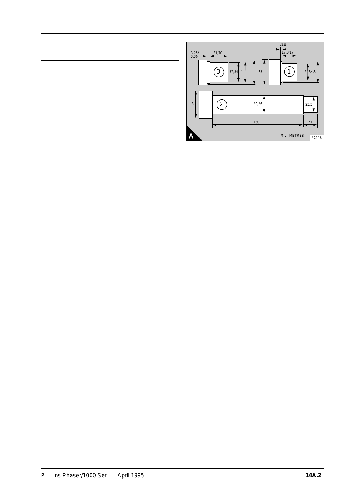
CRANKSHAFT ASSEMBLY 14
aaaaa
a
a
a
a
aaaaa
a
aaaaa
a
a
a
aaa
aaa
aaa
a
a
a
aaaaa
a
a
a
aaaaa
a
a
aaaaaaa
a
a
a
aaaaaaa
aaa
a
a
a
aaa
aaa
aaaaa
a
a
aaaaaaa
a
a
aaa
aaa
aaaaaaaaaaa
a
a
a
aaa
aaa
aaa
a
a
a
a
a
a
aaa
aaa
aaa
aaa
aaa
To remove and to fit the needle roller bearings for the drive shaft14A-13
1 Press out the bearings with a suitable adaptor.
2 Clean the parent bores and lubricate them with
clean engine lubricating oil.
3 Make a suitable adaptor to the dimensions given
in (A2). Fit the rear bearing (14A.24/A7) onto the
adaptor with the stamped face of the bearing
towards the shoulder of the adaptor. Press the
bearing into the parent bore in a continuous
movement until the shoulder of the adaptor is
against the front face of the balancer frame. In this
position the front face of the bearing should be
130,0/131,0 mm (5.12/5.16 in) from the front face
of the balancer frame (14A.24/A).
4 Make a suitable adaptor to the dimensions given
in (A1). Fit the front bearing (14A.24/A10) onto the
adaptor with the stamped face of the bearing
toward the shoulder. Press the bearing into the
parent bore in a continuous movement until the
shoulder of the adaptor is against the front face of
the balancer frame. In this position the front face of
the bearing should be 2,5/3,0 mm (0.01/0.12 in)
from the front face of the balancer frame
(14A.24/A).
3,25/
3,30
38
aaa
aaa
31,70
3
2,5/3,0
aaaaa
a
17,0/17,8
37,84
42
50,8
aaa
a
2
a
a
29,26
130/131
38
aaa
aaaaa
28,45
1
aaaaaaaaa
MILLIMETRES
aaa
a
a
23,5
34,3
aaa
a
a
27
PA118
Perkins Phaser/1000 Series, April 1995 14A.29
Page 96
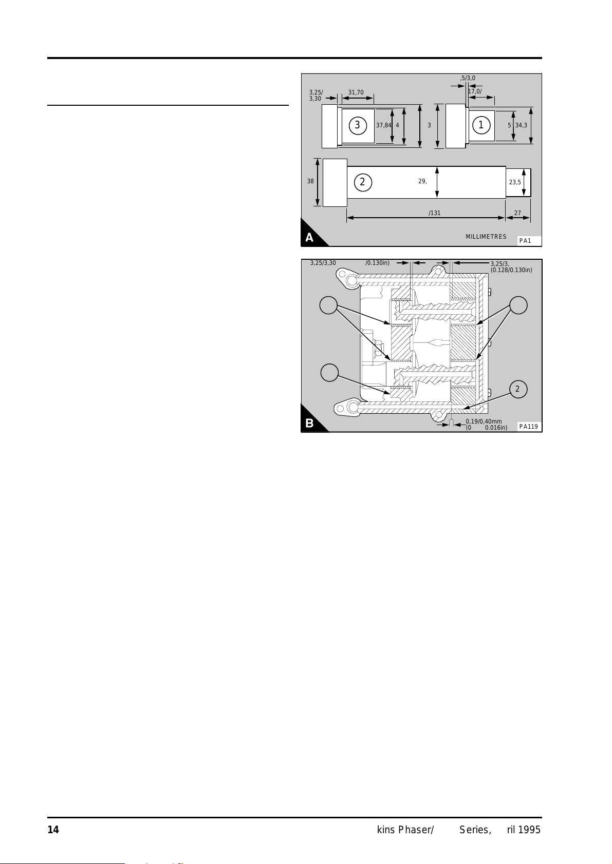
14 CRANKSHAFT ASSEMBLY
aaaaa
a
a
a
a
aaaaa
aaaaa
a
a
aaa
aaa
aaaaa
a
a
aaaaa
a
a
a
aaaaa
a
a
aaaaaaa
a
a
a
aaaaa
a
aaa
a
a
a
aaa
aaa
aaaaa
a
a
aaaaaaa
a
a
aaa
aaa
aaaaaaaaaaa
a
a
a
a
a
a
a
a
a
aaa
aaa
aaa
a
a
a
a
a
a
aaa
aaa
a
a
a
a
a
a
aaa
aaa
aaa
a
a
a
a
a
a
aaaaaaaaaaa
a
a
a
a
a
aaaaaaaaaaa
a
a
a
a
a
aaaaaaaaaaaaaaaaaaaaaaa
a
a
a
a
a
a
To remove and to fit the bushes for the balance weights14A-14
1 Press the bushes out of the balancer frame and
the rear cover with a suitable adaptor.
2 Clean the parent bores and lubricate them with
clean engine lubricating oil.
3 Make a suitable adaptor to the dimensions given
in (A3). Fit a bush onto the adaptor. Press the bush
(B4) into the parent bore in the rear of the balancer
frame (B3), in a continuous movement, until the
shoulder of the adaptor is against the rear face of
the balancer frame. In this position the rear face of
the bush should be 3,25/3,30 mm (0.128/0.130 in)
from the rear face of the balancer frame (B).
Repeat this operation for the other bush.
4 Fit a bush (B1) onto the adaptor and put it into
position at the front end of one of the parent bores
in the rear cover (B2). Press in the bush, in a
continuous movement, until the shoulder of the
adaptor is against the front face of the rear cover.
In this position the front face of the bush should be
3,25/3,30 mm (0.128/0.130 in) from the front face
of the rear cover (B). Repeat this operation for the
other bush.
3,25/
3,30
aaa
aaa
31,70
3
38
3,25/3,30mm (0.128/0.130in)
4
3
2
37,84
aaa
2,5/3,0
aaaaa
a
17,0/17,8
42
50,8
aaa
38
29,26
aaa
aaaaa
130/131
28,45
1
aaaaaaaaa
MILLIMETRES
3,25/3,30mm
aaaaaaaaa
aaaaaaaaa
(0.128/0.130in)
aaa
23,5
a
a
27
34,3
a
aaa
a
PA118
a
a
1
2
0,19/0,40mm
aaaaaaaaa
aaaaaaaaa
(0.007/0.016in)
a
a
PA119
14A.30 Perkins Phaser/1000 Series, April 1995
Page 97

CRANKSHAFT ASSEMBLY 14
Data and dimensions
Note: This information is given as a guide for personnel engaged on engine overhauls. The dimensions
which are shown are those which are mainly used in the factory. The information applies to all engines,
unless an engine type code is shown.
Crankshaft
Diameter of main journals:
- Four cylinder engines . . . . . . . . . . . . . . . . . . . . . . . . . . . . . . . . . . 76,16/76,18 mm (2.998/2.999 in)
- Six cylinder engines . . . . . . . . . . . . . . . . . . . . . . . . . . . . . . . 76,159/76,190 mm (2.9984/2.9996 in)
Maximum wear and ovality on journals and crank pins . . . . . . . . . . . . . . . . . . . . . 0,04 mm (0.0016 in)
Width of front journal . . . . . . . . . . . . . . . . . . . . . . . . . . . . . . . . . . . 36,93/37,69 mm (1.454/1.484 in)
Width of centre journal . . . . . . . . . . . . . . . . . . . . . . . . . . . . . . . . . . 44,15/44,22 mm (1.738/1.741 in)
Width of all other journals . . . . . . . . . . . . . . . . . . . . . . . . . . . . . . . . 39,24/39,35 mm (1.545/1.549 in)
Diameter of crank pins . . . . . . . . . . . . . . . . . . . . . . . . . . . . . . . . . . 63,47/63,49 mm (2.499/2.500 in)
Width of crank pins . . . . . . . . . . . . . . . . . . . . . . . . . . . . . . . . . . . . 40,35/40,42 mm (1.589/1.591 in)
Diameter of flange . . . . . . . . . . . . . . . . . . . . . . . . . . . . . . . . . . . 133,27/133,37 mm (5.247/5.251 in)
Depth of recess for spigot bearing:
- Four cylinder engines . . . . . . . . . . . . . . . . . . . . . . . . . . . . . . . . . 20,22/20,98 mm (0.796/0.826 in)
- Six cylinder engines . . . . . . . . . . . . . . . . . . . . . . . . . . . . . . . . . . . 14,72/15,48 mm (0.579/0.609 in)
Bore of recess for spigot bearing:
- Four cylinder engines . . . . . . . . . . . . . . . . . . . . . . . . . . . . . . . . . . 46,96/46,99 mm (1.849/1.850 in)
- Six cylinder engines . . . . . . . . . . . . . . . . . . . . . . . . . . . . . . . . . . . 51,97/51,99 mm (2.046/2.047 in)
Crankshaft end-float . . . . . . . . . . . . . . . . . . . . . . . . . . . . . . . . . . . . . . 0,05/0,38 mm (0.002/0.015 in)
Maximum permissible end-float . . . . . . . . . . . . . . . . . . . . . . . . . . . . . . . . . . . . . . 0,51 mm (0.020 in)
Fillet radii of journals and crank pins . . . . . . . . . . . . . . . . . . . . . . . . . . . 3,68/3,96 mm (0.145/0.156 in)
Undersize journals and crank pins . . . . . . . . . . . . . . . . . . -0,25 mm (-0.010 in); -0,51 mm (-0.020 in);
. . . . . . . . . . . . . . . . . . . . . . . . . . . . . . . . . . . . . . . . . . . . . . . . . . . . . . . . . . -0,76 mm (-0.030 in).
Crankshaft heat treatment:
- Induction hardened . . . . . . . . . . . . . . . Part numbers 31315662, 31315992, 31315993 and 3131H024
- Nitrocarburised . . . . . . . . . . . . . . . . . . . . . . . . . Part numbers 31315661, 31315991 and 3131H022
- 60 hour Nitride . . . . . . . . . . . . . . . . . . . . . . . . . . . . . . . . . . . . . . . . . . . . . . Part number 3131H021
Crankshaft overhaul
Notes:
• Induction hardened crank shafts need not be hardened after they have been machined undersize.
• Nitrocarburised crankshafts must be hardened again each time they are machined. These crankshafts
must be nitrocarburised or, if this process is not available, they can be nitrided for 20 hours. If neither
process is available a new crankshaft, or Power Exchange crankshaft, must be fitted.
• Crankshafts which have been nitrided for 60 hours can be reground 0,25 mm (0.010 in) without the
need to harden them again.
• Check the crankshaft for cracks before and after it is ground. Demagnetise the crankshaft after it has
been checked for cracks.
• After the crankshaft has been machined remove any sharp corners from the lubricating oil holes.
• Surface finish and fillet radii must be maintained.
Perkins Phaser/1000 Series, April 1995 14A.31
Page 98
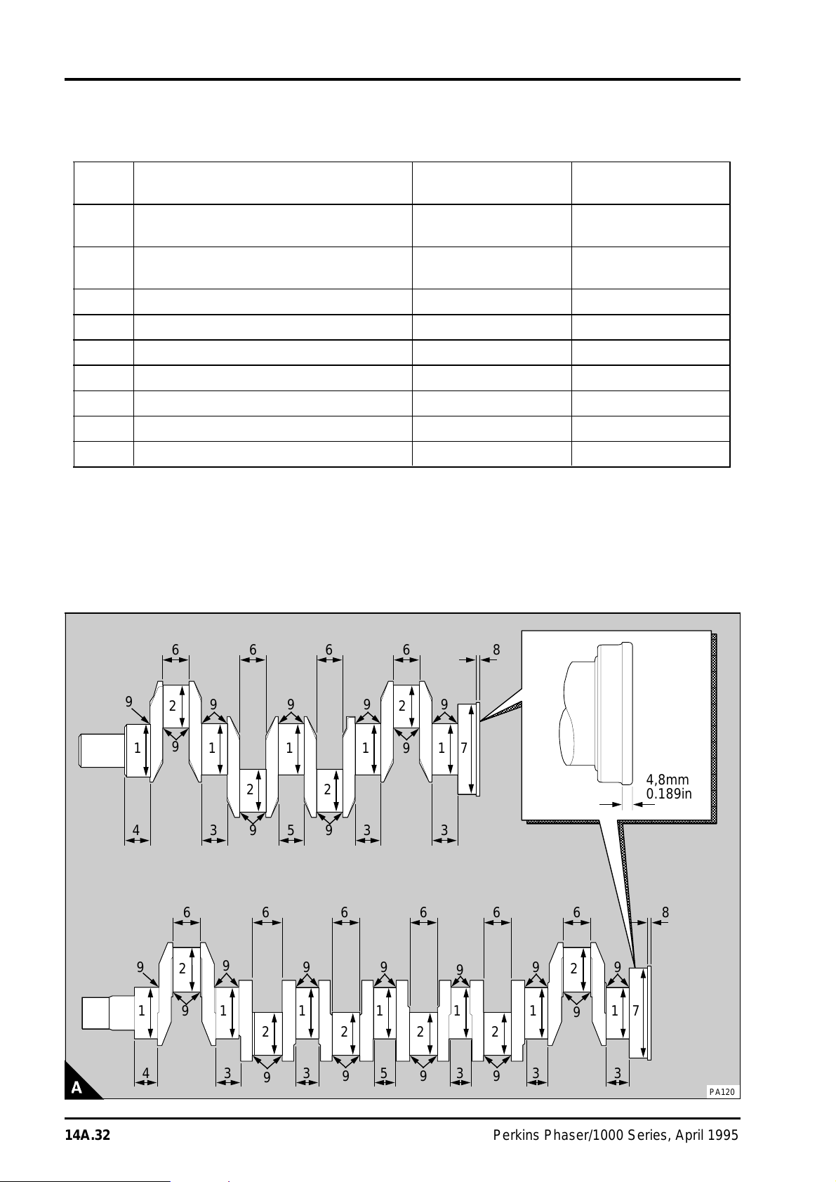
14 CRANKSHAFT ASSEMBLY
aaaaaaaaaaaaaaaaaaaaaaaaaaaaaaaaaaaaaaaaaaaaa
aaaaaaaaaaaaaaaaaaaaaaaaaaaaaaaaaaaaaaaaaaaaa
aaaaaaaaaaaaaaaaaaaaaaaaaaaaaaaaaaaaaaaaaaaaa
aaaaaaaaaaaaaaaaaaaaaaaaaaaaaaaaaaaaaaaaaaaaa
aaaaaaaaaaaaaaaaaaaaaaaaaaaaaaaaaaaaaaaaaaaaa
aaaaaaaaaaaaaaaaaaaaaaaaaaaaaaaaaaaaaaaaaaaaa
aaaaaaaaaaaaaaaaaaaaaaaaaaaaaaaaaaaaaaaaaaaaa
aaaaaaaaaaaaaaaaaaaaaaaaaaaaaaaaaaaaaaaaaaaaa
aaaaaaaaaaaaaaaaaaaaaaaaaaaaaaaaaaaaaaaaaaaaa
aaaaaaaaaaaaaaaaaaaaaaaaaaaaaaaaaaaaaaaaaaaaa
aaaaaaaaaaaaaaaaaaaaaaaaaaaaaaaaaaaaaaaaaaaaa
aaaaaaaaaaaaaaaaaaaaaaaaaaaaaaaaaaaaaaaaaaaaa
aaaaaaaaaaaaaaaaaaaaaaaaaaaaaaaaaaaaaaaaaaaaa
aaaaaaaaaaaaaaaaaaaaaaaaaaaaaaaaaaaaaaaaaaaaa
aaaaaaaaaaaaaaaaaaaaaaaaaaaaaaaaaaaaaaaaaaaaa
aaaaaaaaaaaaaaaaaaaaaaaaaaaaaaaaaaaaaaaaaaaaa
aaaaaaaaaaaaaaaaaaaaaaaaaaaaaaaaaaaaaaaaaaaaa
aaaaaaaaaaaaaaaaaaaaaaaaaaaaaaaaaaaaaaaaaaaaa
aaaaaaaaaaaaaaaaaaaaaaaaaaaaaaaaaaaaaaaaaaaaa
aaaaaaaaaaaaaaaaaaaaaaaaaaaaaaaaaaaaaaaaaaaaa
aaaaaaaaaaaaaaaaaaaaaaaaaaaaaaaaaaaaaaaaaaaaa
aaaaaaaaaaaaaaaaaaaaaaaaaaaaaaaaaaaaaaaaaaaaa
aaaaaaaaaaaaaaaaaaaaaaaaaaaaaaaaaaaaaaaaaaaaa
aaaaaaaaaaaaaaaaaaaaaaaaaaaaaaaaaaaaaaaaaaaaa
aaaaaaaaaaaaaaaaaaaaaaaaaaaaaaaaaaaaaaaaaaaaa
aaaaaaaaaaaaaaaaaaaaaaaaaaaaaaaaaaaaaaaaaaaaa
aaaaaaaaaaaaaaaaaaaaaaaaaaaaaaaaaaaaaaaaaaaaa
aaaaaaaaaaaaaaaaaaaaaaaaaaaaaaaaaaaaaaaaaaaaa
aaaaaaaaaaaaaaaaaaaaaaaaaaaaaaaaaaaaaaaaaaaaa
aaaaaaaaaaaaaaaaaaaaaaaaaaaaaaaaaaaaaaaaaaaaa
aaaaaaaaaaaaaaaaaaaaaaaaaaaaaaaaaaaaaaaaaaaaa
aaaaaaaaaaaaaaaaaaaaaaaaaaaaaaaaaaaaaaaaaaaaa
aaaaaaaaaaaaaaaaaaaaaaaaaaaaaaaaaaaaaaaaaaaaa
aaaaaaaaaaaaaaaaaaaaaaaaaaaaaaaaaaaaaaaaaaaaa
aaaaaaaaaaaaaaaaaaaaaaaaaaaaaaaaaaaaaaaaaaaaa
aaaaaaaaaaaaaaaaaaaaaaaaaaaaaaaaaaaaaaaaaaaaa
aaaaaaaaaaaaaaaaaaaaaaaaaaaaaaaaaaaaaaaaaaaaa
aaaaaaaaaaaaaaaaaaaaaaaaaaaaaaaaaaaaaaaaaaaaa
aaaaaaaaaaaaaaaaaaaaaaaaaaaaaaaaaaaaaaaaaaaaa
aaaaaaaaaaaaaaaaaaaaaaaaaaaaaaaaaaaaaaaaaaaaa
aaaaaaaaaaaaaaaaaaaaaaaaaaaaaaaaaaaaaaaaaaaaa
aaaaaaaaaaaaaaaaaaaaaaaaaaaaaaaaaaaaaaaaaaaaa
aaaaaaaaaaaaaaaaaaaaaaaaaaaaaaaaaaaaaaaaaaaaa
aaaaaaaaaaaaaaaaaaaaaaaaaaaaaaaaaaaaaaaaaaaaa
aaaaaaaaaaaaaaaaaaaaaaaaaaaaaaaaaaaaaaaaaaaaa
aaaaaaaaaaaaaaaaaaaaaaaaaaaaaaaaaaaaaaaaaaaaa
aaaaaaaaaaaaaaaaaaaaaaaaaaaaaaaaaaaaaaaaaaaaa
aaaaaaaaaaaaaaaaaaaaaaaaaaaaaaaaaaaaaaaaaaaaa
aaaaaaaaaaaaaaaaaaaaaaaaaaaaaaaaaaaaaaaaaaaaa
aaaaaaaaaaaaaaaaaaaaaaaaaaaaaaaaaaaaaaaaaaaaa
aaaaaaaaaaaaaaaaaaaaaaaaaaaaaaaaaaaaaaaaaaaaa
aaaaaaaaaaaaaaaaaaaaaaaaaaaaaaaaaaaaaaaaaaaaa
aaaaaaaaaaaaaaaaaaaaaaaaaaaaaaaaaaaaaaaaaaaaa
aaaaaaaaaaaaaaaaaaaaaaaaaaaaaaaaaaaaaaaaaaaaa
aaaaaaaaaaaaaaaaaaaaaaaaaaaaaaaaaaaaaaaaaaaaa
aaaaaaaaaaaaaaaaaaaaaaaaaaaaaaaaaaaaaaaaaaaaa
aaaaaaaaaaaaaaaaaaaaaaaaaaaaaaaaaaaaaaaaaaaaa
aaaaaaaaaaaaaaaaaaaaaaaaaaaaaaaaaaaaaaaaaaaaa
aaaaaaaaaaaaaaaaaaaaaaaaaaaaaaaaaaaaaaaaaaaaa
aaaaaaaaaaaaaaaaaaaaaaaaaaaaaaaaaaaaaaaaaaaaa
aaaaaaaaaaaaaaaaaaaaaaaaaaaaaaaaaaaaaaaaaaaaa
aaaaaaaaaaaaaaaaaaaaaaaaaaaaaaaaaaaaaaaaaaaaa
aaa
aaa
aaa
aaa
aaa
aaa
aaa
aaa
a
a
a
a
a
a
a
a
a
a
a
a
a
a
a
a
aaa
aaa
aaa
a
a
a
a
a
a
a
a
a
a
a
a
aaa
aaa
aaa
aaa
aaa
aaa
aaa
a
a
a
a
a
a
a
a
a
a
a
a
a
a
a
a
a
a
a
a
a
a
a
a
a
a
a
a
a
a
a
a
a
a
a
a
a
a
aaa
aaa
aaa
a
a
a
a
a
a
a
a
aaa
aaa
aaa
aaa
aaa
aaa
aaa
aaa
aaa
a
a
a
a
a
a
a
a
a
a
a
a
a
a
aaa
aaa
aaa
aaa
aaa
aaa
a
a
a
a
a
a
a
a
a
a
a
a
aaa
aaa
aaa
a
a
a
a
a
a
aaa
aaa
aaa
aaa
a
a
a
a
a
a
a
a
aaa
aaa
aaa
aaa
a
a
a
a
a
a
a
a
aaa
aaa
aaa
aaa
aaa
aaa
aaa
aaa
aaa
aaa
aaa
aaa
aaa
aaa
aaa
aaa
a
a
a
a
a
a
a
a
a
a
a
a
aaa
aaa
aaa
aaa
aaa
aaa
aaa
aaa
aaa
aaa
aaa
aaa
aaa
aaa
aaa
aaa
aaa
aaa
a
a
a
a
a
a
aaa
aaa
aaa
a
a
a
a
a
a
a
a
a
a
a
a
a
a
a
a
a
a
a
a
a
a
a
a
a
a
a
a
a
a
aaa
aaa
aaa
a
a
a
a
a
a
a
a
a
a
a
a
a
a
a
a
a
a
aaa
aaa
aaa
aaa
aaa
aaa
aaa
aaa
aaa
aaa
aaa
aaa
aaa
aaa
aaa
a
a
a
a
a
a
a
a
a
a
a
a
aaa
aaa
aaa
aaa
aaa
aaa
a
a
a
a
a
a
aaa
aaa
aaa
a
a
a
a
a
a
a
a
a
a
a
a
aaa
aaa
aaa
a
a
a
a
a
a
aaaaaaaaa
a
a
a
a
a
a
a
a
a
The finished sizes for crankshaft journals (A) which have been ground undersize are given in the table
below:
item 0,25 mm (0.010 in) 0,51 mm (0.020 in) 0,76 mm (0.030 in)
1 75,905/75,926 mm
(2.9884/2.9892 in)
2 63,216/63,236 mm
(2.4888/2.4896 in)
3 39,47 mm (1.554 in) maximum
4 37,82 mm (1.489 in) maximum
5 44,68 mm (1.759 in) maximum
6 40,55 mm (1.596 in) maximum
7 133,17 mm (5.243 in) minimum
8 Do not machine this diameter
9 3,68/3,96 mm (0.145/0.156 in)
75,651/75,672 mm
(2.9784/2.9792 in)
62,962/62,982 mm
(2.4788/2.4796 in)
>>
>>
>>
>>
>>
>>
>>
75,397/75,418 mm
(2.9684/2.9692 in)
62,708/62,728 mm
(2.4688/2.4696 in)
Surface finish for journals, crank pins and fillet radii must be 0,4 microns (16 micro inches). Surface finish
for seal area of crankshaft palm must be 0,4/1,1 microns (16/43 micro inches).
6
9
1
4
14A.32 Perkins Phaser/1000 Series, April 1995
9
1
4
9
2
9
1
3
6
2
9
9
1
3
6
2
9
6
2
9
6
9
1
2
5
9
6
9
1
2
3
9
6
9
1
3
9
2
9
1
3
6
9
1
2
5
9
8
7
aaaaaaa
aaaaaaa
aaaaaaa
aaaaaaa
8
a
a
a
a
4,8mm
0.189in
6
9
1
1
6
9
2
9
1
9
7
2
3
3
9
3
PA120
Page 99
CRANKSHAFT ASSEMBLY 14
With the crankshaft on mountings at the front and rear journals, the maximum run-out (total indicator
reading) at the journals must not be more than shown below:
Journal 4 cylinder crankshafts 6 cylinder crankshafts
1 Mounting Mounting
2 0,08 mm (0.003 in) 0,10 mm (0.004 in)
3 0,15 mm (0.006 in) 0,20 mm (0.008 in)
4 0,08 mm (0.003 in) 0,25 mm (0.010 in)
5 Mounting 0,20 mm (0.008 in)
6
7 - Mounting
Run-out must not be opposite. The difference in run-out between one journal and the next must not be
more than 0,10 mm (0.004 in).
Run-out on the crankshaft pulley diameter, rear oil seal diameter and the rear flange diameter must not be
more than 0,05 mm (0.002 in) total indicator reading.
Main bearings
Four cylinder engines:
Type (All bearings) . . . . . . . . . . . . . . . . . . . . . . . . . . . Steel back, 20% tin-aluminium bearing material
Six cylinder engines:
Centre bearing and all Phaser 210Ti bearings . . . . . . . . . . . . . . . . . . Steel back, lead bronze bearing
. . . . . . . . . . . . . . . . . . . . . . . . . . . . . . . . . . . . . . . . . . . . . . . . . . . . . . . . . material with lead finish
All other bearings . . . . . . . . . . . . . . . . . . . . . . . . . . . . Steel back, 20% tin-aluminium bearing material
Bearing width
Four cylinder engines:
Centre bearing . . . . . . . . . . . . . . . . . . . . . . . . . . . . . . . . . . . . . . . . 36,32/36,70 mm (1.430/1.445 in)
All other bearings . . . . . . . . . . . . . . . . . . . . . . . . . . . . . . . . . . . . . . 31,62/31,88 mm (1.245/1.255 in)
Six cylinder engines:
Centre bearing . . . . . . . . . . . . . . . . . . . . . . . . . . . . . . . . . . . . . . . . 36,32/36,70 mm (1.430/1.445 in)
All other bearings . . . . . . . . . . . . . . . . . . . . . . . . . . . . . . . . . . . . . . 30,86/31,12 mm (1.215/1.225 in)
>
0,10 mm (0.004 in)
Bearing thickness at centre
Four cylinder engines:
All bearings . . . . . . . . . . . . . . . . . . . . . . . . . . . . . . . . . . . . . . . . 2,083/2,089 mm (0.0820/0.0823 in)
Six cylinder engines:
Centre bearing and all Phaser 210Ti bearings . . . . . . . . . . . . . . . . 2,087/2,096 mm (0.0822/0.0825 in)
All other bearings . . . . . . . . . . . . . . . . . . . . . . . . . . . . . . . . . . . . 2,083/2,089 mm (0.0820/0.0823 in)
Perkins Phaser/1000 Series, April 1995 14A.33
Page 100

14 CRANKSHAFT ASSEMBLY
Bearing clearance
Four cylinder engines:
All bearings . . . . . . . . . . . . . . . . . . . . . . . . . . . . . . . . . . . . . . . . 0,057/0,117 mm (0.0022/0.0046 in)
Six cylinder engines:
Centre bearing and all Phaser 210Ti bearings . . . . . . . . . . . . . . . . 0,035/0,110 mm (0.0014/0.0043 in)
All other bearings . . . . . . . . . . . . . . . . . . . . . . . . . . . . . . . . . . . 0,047/0,117 mm (0.0018/0.0046 in)
Available undersize bearings . . . . . . . -0,25 mm (-0.010 in); -0,51 mm (-0.020 in); -0,76 mm (-0.030 in).
Crankshaft thrust washers
Type . . . . . . . . . . . . . . . . . . . . . . . . . . . . . . . . . . . . . . . . . . Steel back, lead bronze bearing material
Position . . . . . . . . . . . . . . . . . . . . . . . . . . . . . . . . . . . . . . . . . . . . . Each side of centre main bearing
Thickness:
- Standard . . . . . . . . . . . . . . . . . . . . . . . . . . . . . . . . . . . . . . . . . . . . . 2,26/2,31 mm (0.089/0.091 in)
- Oversize . . . . . . . . . . . . . . . . . . . . . . . . . . . . . . . . . . . . . . . . . . . . . 2,45/2,50 mm (0.096/0.098 in)
Balancer unit
Diameter of drive shaft for front bearing . . . . . . . . . . . . . . . . . . . 28,562/28,575 mm (1.1245/1.1250 in)
Diameter of drive shaft for rear bearing . . . . . . . . . . . . . . . . . . . 23,787/23,800 mm (0.9365/0.9370 in)
Number of teeth on gear of drive shaft . . . . . . . . . . . . . . . . . . . . . . . . . . . . . . . . . . . . . . . . . . . . . 21
Backlash from gear of drive shaft to idler gear . . . . . . . . . . . . . . . . . . . 0,17/0,29 mm (0.007/0.011 in)
End-float of drive shaft . . . . . . . . . . . . . . . . . . . . . . . . . . . . . . . . . . . . 0,13/0,30 mm (0.005/0.012 in)
Diameter of bore for front bearing of drive shaft . . . . . . . . . . . . . 34,912/34,937 mm (1.3745/1.3755 in)
Diameter of bore for rear bearing of drive shaft . . . . . . . . . . . . . . 29,972/29,993 mm (1.1800/1.1808 in)
Diameter of bore for idler gear . . . . . . . . . . . . . . . . . . . . . . . . . . 47,64/47,65 mm (1.8755/1.8760 in)
Diameter of hub of idler gear . . . . . . . . . . . . . . . . . . . . . . . . . . . . 38,09/38,10 mm (1.4996/1.5000 in)
End-float of idler gear . . . . . . . . . . . . . . . . . . . . . . . . . . . . . . . . . . . . . 0,07/0,23 mm (0.003/0.009 in)
Thickness of thrust washer for idler gear . . . . . . . . . . . . . . . . . . . . . . . 4,14/4,29 mm (0.163/0.169 in)
Number of teeth on idler gear . . . . . . . . . . . . . . . . . . . . . . . . . . . . . . . . . . . . . . . . . . . . . . . . . . . 37
Inside diameter of bushes in balancer frame and end cover (fitted) . . . . . . . . . . . . . 38,133/38,174 mm
(1.5013/1.5029 in)
Diameter of spigots for balance weights . . . . . . . . . . . . . . . . . . . 38,054/38,069 mm (1.4982/1.4988 in)
Fit of spigot in bush . . . . . . . . . . . . . . . . . . . . . . . . . . . . . . . . . . 0,064/0,120 mm (0.0025/0.0047 in)
End-float of balance weights . . . . . . . . . . . . . . . . . . . . . . . . . . . . . . . . 0,19/0,40 mm (0.007/0.016 in)
Backlash of gears on balance weights . . . . . . . . . . . . . . . . . . . . . . . . . 0,10/0,27 mm (0.004/0.011 in)
Backlash of drive gear to spline on balance weight . . . . . . . . . . . . . . . . 0,05/0,20 mm (0.002/0.008 in)
Number of teeth on drive gear . . . . . . . . . . . . . . . . . . . . . . . . . . . . . . . . . . . . . . . . . . . . . . . . . . . 24
Number of teeth on spline on balance weight . . . . . . . . . . . . . . . . . . . . . . . . . . . . . . . . . . . . . . . . 16
14A.34 Perkins Phaser/1000 Series, April 1995
 Loading...