


Perkins 4000 Series
4006-23 TAG1A, TAG2A and TAG3A Inline diesel engine
WORKSHOP MANUAL
6 cylinder turbo charged diesel engine for electric power applications
Publication TPD 1511E, Issue 1.
© Proprietary information of Perkins Engines Company Limited, all rights reserved. The information is correct at the time of print.
Published in September 2004 by Technical Publications.
Perkins Engine Company Limited, Peterborough PE1 5NA England
i

This publication is written in
Perkins Approved Clear English
Chapters
1General information
2Specifications
3Cylinder head assembly
4Piston and connecting rod assemblies
5Crankshaft assembly
6Timing case and drive assembly
7Cylinder block assembly
8Engine timing
9Aspiration system
10Lubrication system
11Fuel system
12Cooling system
13Flywheel and housing
14Electrical equipment
15Auxiliary equipment
16Special tools
The following pages contain a detailed table of contents
ii

4000 Series
Contents
1 General information
Introduction .. ... ... ... ... ... ... ... ... ... ... ... ... ... ... ... ... ... ... ... ... ... ... ... ... ... ... ... ... ... ... ... ... ... ... ... 1
Engine views ... ... ... ... ... ... ... ... ... ... ... ... ... ... ... ... ... ... ... ... ... ... ... ... ... ... ... ... ... ... ... ... ... ... ... 2
Engine identification . ... ... ... ... ... ... ... ... ... ... ... ... ... ... ... ... ... ... ... ... ... ... ... ... ... ... ... ... ... ... ... 3
General safety precautions ... ... ... ... ... ... ... ... ... ... ... ... ... ... ... ... ... ... ... ... ... ... ... ... ... ... ... ... 4
Viton seals . ... ... ... ... ... ... ... ... ... ... ... ... ... ... ... ... ... ... ... ... ... ... ... ... ... ... ... ... ... ... ... ... ... ... ... ... 5
Engine lift equipment ... ... ... ... ... ... ... ... ... ... ... ... ... ... ... ... ... ... ... ... ... ... ... ... ... ... ... ... ... ... ... 6
POWERPART recommended consumable products ... ... ... ... ... ... ... ... ... ... ... ... ... ... ... ... 7
2 Specifications
Basic engine data . ... ... ... ... ... ... ... ... ... ... ... ... ... ... ... ... ... ... ... ... ... ... ... ... ... ... ... ... ... ... ... ... 9
Data and dimensions ... ... ... ... ... ... ... ... ... ... ... ... ... ... ... ... ... ... ... ... ... ... ... ... ... ... ... ... ... ... .. 10
3 Cylinder head assembly
General description ... ... ... ... ... ... ... ... ... ... ... ... ... ... ... ... ... ... ... ... ... ... ... ... ... ... ... ... ... ... ... .. 17
Rocker box and valve gear
Operation 3-1 To remove and fit the rocker box and valve gear ... ... ... ... ... ... ... ... ... ... ... .. 18
Valve gear
Operation 3-2 To inspect rockers, bridge pieces and rocker shaft ... ... ... ... ... ... ... ... ... ... .. 20
Workshop Manual, TPD 1511E, issue 1 |
iii |

4000 Series
Operation 3-3 To replace the bridge piece pressure pad .. ... ... ... ... ... ... ... ... ... ... ... ... ... ... 21
Cylinder head
Operation 3-4 To remove and fit the cylinder head . ... ... ... ... ... ... ... ... ... ... ... ... ... ... ... ... ... 22
Valves and springs
Operation 3-5 To remove and fit the valve and the valve springs .. ... ... ... ... ... ... ... ... ... ... 24
Operation 3-6 To inspect . ... ... ... ... ... ... ... ... ... ... ... ... ... ... ... ... ... ... ... ... ... ... ... ... ... ... ... ... ... 26
Valves seats
Operation 3-7 To remove and fit, and reface the valve seats .. ... ... ... ... ... ... ... ... ... ... ... ... 27
Valves guides
Operation 3-8 To remove and fit the valve guides ... ... ... ... ... ... ... ... ... ... ... ... ... ... ... ... ... ... 28
Fuel injector bush
Operation 3-9 To remove and fit a fuel injector bush .. ... ... ... ... ... ... ... ... ... ... ... ... ... ... ... ... 29
Cylinder head
Operation 3-10 To inspect and pressure test ... ... ... ... ... ... ... ... ... ... ... ... ... ... ... ... ... ... ... ... 33
Manifolds
Operation 3-11 To remove and fit the induction manifold . ... ... ... ... ... ... ... ... ... ... ... ... ... ... 34
Operation 3-12 To remove and fit the exhaust manifold ... ... ... ... ... ... ... ... ... ... ... ... ... ... ... 35
4 Piston and connecting rod assemblies
General description . ... ... ... ... ... ... ... ... ... ... ... ... ... ... ... ... ... ... ... ... ... ... ... ... ... ... ... ... ... ... ... 39
Piston and connecting rod
Operation 4-1 To remove ... ... ... ... ... ... ... ... ... ... ... ... ... ... ... ... ... ... ... ... ... ... ... ... ... ... ... ... ... 40 Operation 4-2 To fit ... ... ... ... ... ... ... ... ... ... ... ... ... ... ... ... ... ... ... ... ... ... ... ... ... ... ... ... ... ... ... ... 43
Piston rings
Operation 4-3 To remove ... ... ... ... ... ... ... ... ... ... ... ... ... ... ... ... ... ... ... ... ... ... ... ... ... ... ... ... ... 45 Operation 4-4 To fit ... ... ... ... ... ... ... ... ... ... ... ... ... ... ... ... ... ... ... ... ... ... ... ... ... ... ... ... ... ... ... ... 46
Piston and connecting rod assembly
Operation 4-5 To dismantle Operation 4-6 To assemble
... ... ... ... ... ... ... ... ... ... ... ... ... ... ... ... ... ... ... ... ... ... ... ... ... ... ... ... 47
... ... ... ... ... ... ... ... ... ... ... ... ... ... ... ... ... ... ... ... ... ... ... ... ... ... ... ... 47
Piston and piston rings
Operation 4-7 To inspect . ... ... ... ... ... ... ... ... ... ... ... ... ... ... ... ... ... ... ... ... ... ... ... ... ... ... ... ... ... 49
Connecting rod
Operation 4-8 To inspect . ... ... ... ... ... ... ... ... ... ... ... ... ... ... ... ... ... ... ... ... ... ... ... ... ... ... ... ... ... 50
iv |
Workshop Manual, TPD 1511E, issue 1 |

4000 Series
Small end bush
Operation 4-9 To inspect .. ... ... ... ... ... ... ... ... ... ... ... ... ... ... ... ... ... ... ... ... ... ... ... ... ... ... ... ... .. 51 Operation 4-10 To remove and fit .. ... ... ... ... ... ... ... ... ... ... ... ... ... ... ... ... ... ... ... ... ... ... ... ... .. 51
Piston cooling jets
Operation 4-11 To remove .. ... ... ... ... ... ... ... ... ... ... ... ... ... ... ... ... ... ... ... ... ... ... ... ... ... ... ... .. 52 Operation 4-12 To fit .. ... ... ... ... ... ... ... ... ... ... ... ... ... ... ... ... ... ... ... ... ... ... ... ... ... ... ... ... ... ... .. 53
5 Crankshaft assembly
General description ... ... ... ... ... ... ... ... ... ... ... ... ... ... ... ... ... ... ... ... ... ... ... ... ... ... ... ... ... ... ... .. 55
Crankshaft pulley and adaptor
Operation 5-1 To remove .. ... ... ... ... ... ... ... ... ... ... ... ... ... ... ... ... ... ... ... ... ... ... ... ... ... ... ... ... .. 56 Operation 5-2 To fit . ... ... ... ... ... ... ... ... ... ... ... ... ... ... ... ... ... ... ... ... ... ... ... ... ... ... ... ... ... ... ... .. 57
Crankshaft vibration damper assembly
Operation 5-3 To remove .. ... ... ... ... ... ... ... ... ... ... ... ... ... ... ... ... ... ... ... ... ... ... ... ... ... ... ... ... .. 58 Operation 5-4 To fit . ... ... ... ... ... ... ... ... ... ... ... ... ... ... ... ... ... ... ... ... ... ... ... ... ... ... ... ... ... ... ... .. 59
Crankshaft
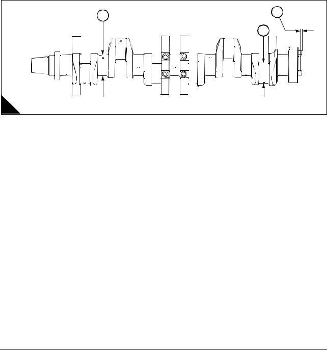
Operation 5-5 To remove ... ... ... ... ... ... ... ... ... ... ... ... ... ... ... ... ... ... ... ... ... ... ... ... ... ... ... ... .. 60 Operation 5-6 To fit . ... ... ... ... ... ... ... ... ... ... ... ... ... ... ... ... ... ... ... ... ... ... ... ... ... ... ... ... ... ... ... .. 61 Operation 5-7 To check the crankshaft end float ... ... ... ... ... ... ... ... ... ... ... ... ... ... ... ... ... ... .. 63
6 Gearcase and drive assembly
General description ... ... ... ... ... ... ... ... ... ... ... ... ... ... ... ... ... ... ... ... ... ... ... ... ... ... ... ... ... ... ... .. 65
Gearcase
Operation 6-1 To remove .. ... ... ... ... ... ... ... ... ... ... ... ... ... ... ... ... ... ... ... ... ... ... ... ... ... ... ... ... .. 66 Operation 6-2 To fit . ... ... ... ... ... ... ... ... ... ... ... ... ... ... ... ... ... ... ... ... ... ... ... ... ... ... ... ... ... ... ... .. 67
Front oil seal
Operation 6-3 To remove .. ... ... ... ... ... ... ... ... ... ... ... ... ... ... ... ... ... ... ... ... ... ... ... ... ... ... ... ... .. 68 Operation 6-4 To fit . ... ... ... ... ... ... ... ... ... ... ... ... ... ... ... ... ... ... ... ... ... ... ... ... ... ... ... ... ... ... ... .. 68
Camshaft gear
Operation 6-5 To remove .. ... ... ... ... ... ... ... ... ... ... ... ... ... ... ... ... ... ... ... ... ... ... ... ... ... ... ... ... .. 69 Operation 6-6 To fit . ... ... ... ... ... ... ... ... ... ... ... ... ... ... ... ... ... ... ... ... ... ... ... ... ... ... ... ... ... ... ... .. 70
Idler gear
Operation 6-7 To remove .. ... ... ... ... ... ... ... ... ... ... ... ... ... ... ... ... ... ... ... ... ... ... ... ... ... ... ... ... .. 71 Operation 6-8 To fit . ... ... ... ... ... ... ... ... ... ... ... ... ... ... ... ... ... ... ... ... ... ... ... ... ... ... ... ... ... ... ... .. 72
Operation 6-9 To check the hub and renew the idler gear bush ... ... ... ... ... ... ... ... ... ... ... .. 73
Workshop Manual, TPD 1511E, issue 1 |
v |

4000 Series
Cam followers
Operation 6-10 To remove and fit . ... ... ... ... ... ... ... ... ... ... ... ... ... ... ... ... ... ... ... ... ... ... ... ... ... 74 Operation 6-11 To check ... ... ... ... ... ... ... ... ... ... ... ... ... ... ... ... ... ... ... ... ... ... ... ... ... ... ... ... ... 75
Camshaft
Operation 6-12 To remove .. ... ... ... ... ... ... ... ... ... ... ... ... ... ... ... ... ... ... ... ... ... ... ... ... ... ... ... ... 76 Operation 6-13 To check the camshaft .. ... ... ... ... ... ... ... ... ... ... ... ... ... ... ... ... ... ... ... ... ... ... 77 Operation 6-14 To fit . ... ... ... ... ... ... ... ... ... ... ... ... ... ... ... ... ... ... ... ... ... ... ... ... ... ... ... ... ... ... ... 78 Operation 6-15 To remove and fit the camshaft bush ... ... ... ... ... ... ... ... ... ... ... ... ... ... ... ... 79
Crankshaft gear
Operation 6-16 To remove .. ... ... ... ... ... ... ... ... ... ... ... ... ... ... ... ... ... ... ... ... ... ... ... ... ... ... ... ... 80 Operation 6-17 To fit . ... ... ... ... ... ... ... ... ... ... ... ... ... ... ... ... ... ... ... ... ... ... ... ... ... ... ... ... ... ... ... 81
Back Plate
Operation 6-18 To remove .. ... ... ... ... ... ... ... ... ... ... ... ... ... ... ... ... ... ... ... ... ... ... ... ... ... ... ... ... 82 Operation 6-19 To fit . ... ... ... ... ... ... ... ... ... ... ... ... ... ... ... ... ... ... ... ... ... ... ... ... ... ... ... ... ... ... ... 83
7 Crankcase
General Description . ... ... ... ... ... ... ... ... ... ... ... ... ... ... ... ... ... ... ... ... ... ... ... ... ... ... ... ... ... ... ... 85
Crankcase
Operation 7-1 To remove ... ... ... ... ... ... ... ... ... ... ... ... ... ... ... ... ... ... ... ... ... ... ... ... ... ... ... ... ... 86 Operation 7-2 To fit ... ... ... ... ... ... ... ... ... ... ... ... ... ... ... ... ... ... ... ... ... ... ... ... ... ... ... ... ... ... ... ... 87 Operation 7-3 To inspect . ... ... ... ... ... ... ... ... ... ... ... ... ... ... ... ... ... ... ... ... ... ... ... ... ... ... ... ... ... 87
Cylinder Liner
Operation 7-4 To inspect . ... ... ... ... ... ... ... ... ... ... ... ... ... ... ... ... ... ... ... ... ... ... ... ... ... ... ... ... ... 88 Operation 7-5 To remove ... ... ... ... ... ... ... ... ... ... ... ... ... ... ... ... ... ... ... ... ... ... ... ... ... ... ... ... ... 89 Operation 7-6 To fit liner .. ... ... ... ... ... ... ... ... ... ... ... ... ... ... ... ... ... ... ... ... ... ... ... ... ... ... ... ... ... 90
8 Engine timing
Operation 8-1 To set number 1 piston to Top Dead Centre (TDC) ... ... ... ... ... ... ... ... ... ... 91
Operation 8-2 Calibrating fuel injectors .. ... ... ... ... ... ... ... ... ... ... ... ... ... ... ... ... ... ... ... ... ... ... 92 Operation 8-3 Setting governor on zero fuel . ... ... ... ... ... ... ... ... ... ... ... ... ... ... ... ... ... ... ... ... 94 Operation 8-4 Applying pressure to the timing pin .. ... ... ... ... ... ... ... ... ... ... ... ... ... ... ... ... ... 95 Operation 8-5 Timing the fuel injectors ... ... ... ... ... ... ... ... ... ... ... ... ... ... ... ... ... ... ... ... ... ... ... 96
9 Aspiration system
General description . ... ... ... ... ... ... ... ... ... ... ... ... ... ... ... ... ... ... ... ... ... ... ... ... ... ... ... ... ... ... ... 99
vi |
Workshop Manual, TPD 1511E, issue 1 |

4000 Series
How to check the air restriction indicator
Operation 9-1 To check and reset . ... ... ... ... ... ... ... ... ... ... ... ... ... ... ... ... ... ... ... ... ... ... ... ... 100
Air filter element
Operation 9-2 To remove and fit ... ... ... ... ... ... ... ... ... ... ... ... ... ... ... ... ... ... ... ... ... ... ... ... ... |
101 |
Air filter and pipe connection
Operation 9-3 To remove .. ... ... ... ... ... ... ... ... ... ... ... ... ... ... ... ... ... ... ... ... ... ... ... ... ... ... ... ... 102 Operation 9-4 To fit . ... ... ... ... ... ... ... ... ... ... ... ... ... ... ... ... ... ... ... ... ... ... ... ... ... ... ... ... ... ... ... 103
Air filter bracket
Operation 9-5 To remove .. ... ... ... ... ... ... ... ... ... ... ... ... ... ... ... ... ... ... ... ... ... ... ... ... ... ... ... ... 104 Operation 9-6 To fit . ... ... ... ... ... ... ... ... ... ... ... ... ... ... ... ... ... ... ... ... ... ... ... ... ... ... ... ... ... ... ... 104
Turbocharger |
... |
... ... ... ... ... ... ... ... ... ... ... ... ... ... ... ... ... ... ... ... ... ... ... ... ... ... ... ... ... ... ... ... ... |
105 |
Operation 9-7 |
To remove ... ... ... ... ... ... ... ... ... ... ... ... ... ... ... ... ... ... ... ... ... ... ... ... ... ... ... ... |
106 |
|
Operation 9-8 |
To fit ... ... ... ... ... ... ... ... ... ... ... ... ... ... ... ... ... ... ... ... ... ... ... ... ... ... ... ... ... ... ... |
108 |
|
Air pipe connection |
|
||
Operation 9-9 |
To remove ... ... ... ... ... ... ... ... ... ... ... ... ... ... ... ... ... ... ... ... ... ... ... ... ... ... ... ... |
110 |
|
Operation 9-10 |
To fit . ... ... ... ... ... ... ... ... ... ... ... ... ... ... ... ... ... ... ... ... ... ... ... ... ... ... ... ... ... ... |
111 |
|
Engine breather |
|
||
Operation 9-11 |
To remove breather system ... ... ... ... ... ... ... ... ... ... ... ... ... ... ... ... ... ... ... ... |
112 |
|
Operation 9-12 |
To fit the breather system ... ... ... ... ... ... ... ... ... ... ... ... ... ... ... ... ... ... ... ... ... |
113 |
|
10 Lubrication system
General Description .. ... ... ... ... ... ... ... ... ... ... ... ... ... ... ... ... ... ... ... ... ... ... ... ... ... ... ... ... ... ... |
115 |
Filter Canister
Operation 10-1 To renew .. ... ... ... ... ... ... ... ... ... ... ... ... ... ... ... ... ... ... ... ... ... ... ... ... ... ... ... ... 117
Filter head
Operation 10-2 To remove and to fit . ... ... ... ... ... ... ... ... ... ... ... ... ... ... ... ... ... ... ... ... ... ... ... 118
Lubricating oil sump |
|
|
Operation 10-3 |
To remove ... ... ... ... ... ... ... ... ... ... ... ... ... ... ... ... ... ... ... ... ... ... ... ... ... ... ... ... |
119 |
Operation 10-4 |
To fit .. ... ... ... ... ... ... ... ... ... ... ... ... ... ... ... ... ... ... ... ... ... ... ... ... ... ... ... ... ... ... |
120 |
Dipstick tube |
|
|
Operation 10-5 |
To remove and to fit . ... ... ... ... ... ... ... ... ... ... ... ... ... ... ... ... ... ... ... ... ... ... ... |
121 |
Oil strainer and suction pipe
Operation 10-6 To remove and to fit . ... ... ... ... ... ... ... ... ... ... ... ... ... ... ... ... ... ... ... ... ... ... ... 122
Workshop Manual, TPD 1511E, issue 1 |
vii |

4000 Series
Lubricating oil pump
Operation 10-7 To remove .. ... ... ... ... ... ... ... ... ... ... ... ... ... ... ... ... ... ... ... ... ... ... ... ... ... ... ... .. 123 Operation 10-8 To fit . ... ... ... ... ... ... ... ... ... ... ... ... ... ... ... ... ... ... ... ... ... ... ... ... ... ... ... ... ... ... ..124 Operation 10-9 To dismantle . ... ... ... ... ... ... ... ... ... ... ... ... ... ... ... ... ... ... ... ... ... ... ... ... ... ... ..125 Operation 10-10 To assemble ... ... ... ... ... ... ... ... ... ... ... ... ... ... ... ... ... ... ... ... ... ... ... ... ... ... .. 126 Operation 10-11 To inspect ... ... ... ... ... ... ... ... ... ... ... ... ... ... ... ... ... ... ... ... ... ... ... ... ... ... ... .. 128
Relief Valve
Operation 10-12 To dismantle and to assemble .. ... ... ... ... ... ... ... ... ... ... ... ... ... ... ... ... ... .. 129 Operation 10-13 To inspect ... ... ... ... ... ... ... ... ... ... ... ... ... ... ... ... ... ... ... ... ... ... ... ... ... ... ... .. 130
Fuel lift pump drive unit
Operation 10-14 To renew .. ... ... ... ... ... ... ... ... ... ... ... ... ... ... ... ... ... ... ... ... ... ... ... ... ... ... ... .. 131
Rotor end float
Operation 10-15 To inspect ... ... ... ... ... ... ... ... ... ... ... ... ... ... ... ... ... ... ... ... ... ... ... ... ... ... ... .. 132
Drive shaft bearings
Operation 10-16 To remove and to fit . ... ... ... ... ... ... ... ... ... ... ... ... ... ... ... ... ... ... ... ... ... ... .. 133
11 Fuel system
General description . ... ... ... ... ... ... ... ... ... ... ... ... ... ... ... ... ... ... ... ... ... ... ... ... ... ... ... ... ... ... ..135
Fuel filter
Operation 11-1 To remove and fit . ... ... ... ... ... ... ... ... ... ... ... ... ... ... ... ... ... ... ... ... ... ... ... ... ..136
Fuel injector unit
Operation 11-2 To remove the fuel injector unit .. ... ... ... ... ... ... ... ... ... ... ... ... ... ... ... ... ... .. 137
Operation 11-3 To disassemble and to check a fuel injector unit ... ... ... ... ... ... ... ... ... ... .. 139
Operation 11-4 To assemble the fuel injector unit ... ... ... ... ... ... ... ... ... ... ... ... ... ... ... ... ... ..143
To test and set the fuel injector
Operation 11-5 To test and set ... ... ... ... ... ... ... ... ... ... ... ... ... ... ... ... ... ... ... ... ... ... ... ... ... ..146 Operation 11-6 To fit a fuel injector .. ... ... ... ... ... ... ... ... ... ... ... ... ... ... ... ... ... ... ... ... ... ... ... .. 151
Fuel Lift pump
Operation 11-7 To remove and to fit ... ... ... ... ... ... ... ... ... ... ... ... ... ... ... ... ... ... ... ... ... ... ... ..152
Fuel control shaft
Operation 11-8 To remove .. ... ... ... ... ... ... ... ... ... ... ... ... ... ... ... ... ... ... ... ... ... ... ... ... ... ... ... .. 153 Operation 11-9 To inspect .. ... ... ... ... ... ... ... ... ... ... ... ... ... ... ... ... ... ... ... ... ... ... ... ... ... ... ... .. 154 Operation 11-10 To fit .. ... ... ... ... ... ... ... ... ... ... ... ... ... ... ... ... ... ... ... ... ... ... ... ... ... ... ... ... ... ..155
viii |
Workshop Manual, TPD 1511E, issue 1 |

4000 Series
12 Cooling system
Coolant pipework
Operation 12-1 To remove and fit the coolant pipework . ... ... ... ... ... ... ... ... ... ... ... ... ... ... 158
Thermostat |
|
|
Operation 12-2 |
To remove the thermostat .. ... ... ... ... ... ... ... ... ... ... ... ... ... ... ... ... ... ... ... ... |
159 |
Operation 12-3 |
To fit the thermostat . ... ... ... ... ... ... ... ... ... ... ... ... ... ... ... ... ... ... ... ... ... ... ... |
160 |
Operation 12-4 |
To test . ... ... ... ... ... ... ... ... ... ... ... ... ... ... ... ... ... ... ... ... ... ... ... ... ... ... ... ... ... |
161 |
Thermostat housing
Operation 12-5 To remove and fit the thermostat housing . ... ... ... ... ... ... ... ... ... ... ... ... ... 162
Coolant pump
Operation 12-6 To remove the coolant pump . ... ... ... ... ... ... ... ... ... ... ... ... ... ... ... ... ... ... ... 164 Operation 12-7 To fit the coolant pump ... ... ... ... ... ... ... ... ... ... ... ... ... ... ... ... ... ... ... ... ... ... 166 Operation 12-8 To disassemble the coolant pump ... ... ... ... ... ... ... ... ... ... ... ... ... ... ... ... ... 168 Operation 12-9 To assemble the coolant pump . ... ... ... ... ... ... ... ... ... ... ... ... ... ... ... ... ... ... 169
Fan Guards
Operation 12-10 To remove and fit
Fan
Operation 12-11 To remove and fit
... ... ... ... ... ... ... ... ... ... ... ... ... ... ... ... ... ... ... ... ... ... ... ... 171
... ... ... ... ... ... ... ... ... ... ... ... ... ... ... ... ... ... ... ... ... ... ... ... 171
Fan drive belts
Operation 12-12 To check the fan drive belts . ... ... ... ... ... ... ... ... ... ... ... ... ... ... ... ... ... ... ... 172 Operation 12-13 To adjust the fan drive belts ... ... ... ... ... ... ... ... ... ... ... ... ... ... ... ... ... ... ... 172 Operation 12-14 To remove and fit the drive belts ... ... ... ... ... ... ... ... ... ... ... ... ... ... ... ... ... 173
Fan drive |
|
Operation 12-15 To remove and fit ... ... ... ... ... ... ... ... ... ... ... ... ... ... ... ... ... ... ... ... ... ... ... ... |
174 |
Lubricating oil cooler |
|
Operation 12-16 To remove ... ... ... ... ... ... ... ... ... ... ... ... ... ... ... ... ... ... ... ... ... ... ... ... ... ... ... |
176 |
Operation 12-17 To fit ... ... ... ... ... ... ... ... ... ... ... ... ... ... ... ... ... ... ... ... ... ... ... ... ... ... ... ... ... ... |
177 |
Operation 12-18 To disassemble and clean the oil cooler tube stack . ... ... ... ... ... ... ... ... |
178 |
Operation 12-19 To assemble the oil cooler tube stack .. ... ... ... ... ... ... ... ... ... ... ... ... ... ... |
179 |
Operation 12-20 To pressure test the oil cooler ... ... ... ... ... ... ... ... ... ... ... ... ... ... ... ... ... ... |
180 |
Radiator |
|
Operation 12-21 To remove ... ... ... ... ... ... ... ... ... ... ... ... ... ... ... ... ... ... ... ... ... ... ... ... ... ... ... |
181 |
Operation 12-22 To fit ... ... ... ... ... ... ... ... ... ... ... ... ... ... ... ... ... ... ... ... ... ... ... ... ... ... ... ... ... ... |
182 |
Workshop Manual, TPD 1511E, issue 1 |
ix |

4000 Series
13 Flywheel and housing
General description . ... ... ... ... ... ... ... ... ... ... ... ... ... ... ... ... ... ... ... ... ... ... ... ... ... ... ... ... ... ... ..183
Flywheel
Operation 13-1 To remove and to fit the flywheel ... ... ... ... ... ... ... ... ... ... ... ... ... ... ... ... ... .. 184
Gear ring
Operation 13-2 To remove and to fit the gear ring .. ... ... ... ... ... ... ... ... ... ... ... ... ... ... ... ... ..186
Flywheel Housing
Operation 13-3 To remove and to fit the flywheel housing ... ... ... ... ... ... ... ... ... ... ... ... ... .. 187
Flywheel housing oil seal
Operation 13-4 To remove and to fit the flywheel housing oil seal . ... ... ... ... ... ... ... ... ... .. 189
14 Electrical equipment
General description . ... ... ... ... ... ... ... ... ... ... ... ... ... ... ... ... ... ... ... ... ... ... ... ... ... ... ... ... ... ... ..191
Alternator . ... ... ... ... ... ... ... ... ... ... ... ... ... ... ... ... ... ... ... ... ... ... ... ... ... ... ... ... ... ... ... ... ... ... ... .. 192
Operation 14-1 To check the drive belts . ... ... ... ... ... ... ... ... ... ... ... ... ... ... ... ... ... ... ... ... ... ..192 Operation 14-2 To adjust the drive belt tension ... ... ... ... ... ... ... ... ... ... ... ... ... ... ... ... ... ... ..193 Operation 14-3 To remove the alternator ... ... ... ... ... ... ... ... ... ... ... ... ... ... ... ... ... ... ... ... ... ..193 Operation 14-4 Remove the alternator drive pulley ... ... ... ... ... ... ... ... ... ... ... ... ... ... ... ... ..194 Operation 14-5 To fit the alternator drive pulley ... ... ... ... ... ... ... ... ... ... ... ... ... ... ... ... ... ... ..195 Operation 14-6 To fit the alternator .. ... ... ... ... ... ... ... ... ... ... ... ... ... ... ... ... ... ... ... ... ... ... ... .. 196 Operation 14-7 To maintain ... ... ... ... ... ... ... ... ... ... ... ... ... ... ... ... ... ... ... ... ... ... ... ... ... ... ... .. 196
Starter motor .. ... ... ... ... ... ... ... ... ... ... ... ... ... ... ... ... ... ... ... ... ... ... ... ... ... ... ... ... ... ... ... ... ... .. 197
Operation 14-8 To remove ... ... ... ... ... ... ... ... ... ... ... ... ... ... ... ... ... ... ... ... ... ... ... ... ... ... ... .. 197 Operation 14-9 To Fit .. ... ... ... ... ... ... ... ... ... ... ... ... ... ... ... ... ... ... ... ... ... ... ... ... ... ... ... ... ... ..197
The air starter motor system ... ... ... ... ... ... ... ... ... ... ... ... ... ... ... ... ... ... ... ... ... ... ... ... ... ... .. 198
Operation 14-10 To remove .. ... ... ... ... ... ... ... ... ... ... ... ... ... ... ... ... ... ... ... ... ... ... ... ... ... ... .. 201 Operation 14-11 To fit . ... ... ... ... ... ... ... ... ... ... ... ... ... ... ... ... ... ... ... ... ... ... ... ... ... ... ... ... ... .. 201
Stop solenoid
Operation 14-12 To remove .. ... ... ... ... ... ... ... ... ... ... ... ... ... ... ... ... ... ... ... ... ... ... ... ... ... ... .. 202 Operation 14-13 To fit . ... ... ... ... ... ... ... ... ... ... ... ... ... ... ... ... ... ... ... ... ... ... ... ... ... ... ... ... ... .. 202
Digital Electronic Governor . ... ... ... ... ... ... ... ... ... ... ... ... ... ... ... ... ... ... ... ... ... ... ... ... ... ... ..203
Description of System ... ... ... ... ... ... ... ... ... ... ... ... ... ... ... ... ... ... ... ... ... ... ... ... ... ... ... ... ... .. 206
Block diagram of the governor system ... ... ... ... ... ... ... ... ... ... ... ... ... ... ... ... ... ... ... ... ... ..207
x |
Workshop Manual, TPD 1511E, issue 1 |
4000 Series |
|
|
Magnetic pick-up |
|
|
Operation 14-14 To clean the magnetic pick-up ... ... ... ... ... ... ... ... ... ... ... ... ... ... ... ... ... ... |
208 |
|
Operation 14-15 To remove the actuator . ... ... ... ... ... ... ... ... ... ... ... ... ... ... ... ... ... ... ... ... ... |
209 |
|
Operation 14-16 To fit ... ... ... ... ... ... ... ... ... ... ... ... ... ... ... ... ... ... ... ... ... ... ... ... ... ... ... ... ... ... |
210 |
|
Specification of Governor system ... ... ... ... ... ... ... ... ... ... ... ... ... ... ... ... ... ... ... ... ... ... ... ... |
211 |
|
Operation 14-17 |
To remove the digital control box ... ... ... ... ... ... ... ... ... ... ... ... ... ... ... ... ... |
211 |
Operation 14-18 |
To Fit the digital control box ... ... ... ... ... ... ... ... ... ... ... ... ... ... ... ... ... ... ... |
211 |
Feedback Setting
Operation 14-19 To adjust ... ... ... ... ... ... ... ... ... ... ... ... ... ... ... ... ... ... ... ... ... ... ... ... ... ... ... ... 212
Configuration ... ... ... ... ... ... ... ... ... ... ... ... ... ... ... ... ... ... ... ... ... ... ... ... ... ... ... ... ... ... ... ... ... ... 216
External Speed Control Input ... ... ... ... ... ... ... ... ... ... ... ... ... ... ... ... ... ... ... ... ... ... ... ... ... ... |
216 |
Changing the governor configuration ... ... ... ... ... ... ... ... ... ... ... ... ... ... ... ... ... ... ... ... ... ... |
217 |
Operation 14-20 To adjust ... ... ... ... ... ... ... ... ... ... ... ... ... ... ... ... ... ... ... ... ... ... ... ... ... ... ... ... |
217 |
Single/Parallel Generator (Non Heinzmann Load Sharing) |
|
Operation 14-21 To adjust ... ... ... ... ... ... ... ... ... ... ... ... ... ... ... ... ... ... ... ... ... ... ... ... ... ... ... ... |
218 |
Single/Parallel Generator with Droop |
|
Operation 14-22 To adjust ... ... ... ... ... ... ... ... ... ... ... ... ... ... ... ... ... ... ... ... ... ... ... ... ... ... ... ... |
219 |
Parallel Generator Heinzmann (SyG02/LMG10-01) |
|
Operation 14-23 To adjust ... ... ... ... ... ... ... ... ... ... ... ... ... ... ... ... ... ... ... ... ... ... ... ... ... ... ... ... |
220 |
Parallel Generator Heinzmann Digital Theseus |
|
Operation 14-24 To adjust ... ... ... ... ... ... ... ... ... ... ... ... ... ... ... ... ... ... ... ... ... ... ... ... ... ... ... ... |
221 |
Parallel Generator Variable Speed in Droop Range |
|
Operation 14-25 To adjust ... ... ... ... ... ... ... ... ... ... ... ... ... ... ... ... ... ... ... ... ... ... ... ... ... ... ... ... |
222 |
Other settings |
|
Operation 14-26 Load Control Settings ... ... ... ... ... ... ... ... ... ... ... ... ... ... ... ... ... ... ... ... ... ... |
223 |
PID parameters
Operation 14-27 To adjust ... ... ... ... ... ... ... ... ... ... ... ... ... ... ... ... ... ... ... ... ... ... ... ... ... ... ... ... 226
PID Maps
Operation 14-28 To adjust ... ... ... ... ... ... ... ... ... ... ... ... ... ... ... ... ... ... ... ... ... ... ... ... ... ... ... ... 227
Speed Ramps ... ... ... ... ... ... ... ... ... ... ... ... ... ... ... ... ... ... ... ... ... ... ... ... ... ... ... ... ... ... ... ... ... ... 228
Sectional Speed Ramp
Operation 14-29 To adjust ... ... ... ... ... ... ... ... ... ... ... ... ... ... ... ... ... ... ... ... ... ... ... ... ... ... ... ... 229
Workshop Manual, TPD 1511E, issue 1 |
xi |

External connections – Control box connector
Alternative Connections for Speed Setting Inputs
Wiring detail, digital control box in IP enclosure – production engines Fault Tracing
Error Codes
Low oil High water temperature switch
Operation 14-30 To remove ... ... ... ... ... ... ... ... ... ... ... ... ... ... ... ... ... ... ... ... ... ... ... ... ... ... ... ..242 Operation 14-31 To fit .. ... ... ... ... ... ... ... ... ... ... ... ... ... ... ... ... ... ... ... ... ... ... ... ... ... ... ... ... ... ..242
Switch connections
Operation 14-32 To remove and fit .. ... ... ... ... ... ... ... ... ... ... ... ... ... ... ... ... ... ... ... ... ... ... ... .. 243
Switch setting ... ... ... ... ... ... ... ... ... ... ... ... ... ... ... ... ... ... ... ... ... ... ... ... ... ... ... ... ... ... ... ... ... .. 243
15 Auxiliary equipment
Operation 15-1 To remove .. ... ... ... ... ... ... ... ... ... ... ... ... ... ... ... ... ... ... ... ... ... ... ... ... ... ... ... .. 246 Operation 15-2 To fit . ... ... ... ... ... ... ... ... ... ... ... ... ... ... ... ... ... ... ... ... ... ... ... ... ... ... ... ... ... ... ..247 Operation 15-3 To remove .. ... ... ... ... ... ... ... ... ... ... ... ... ... ... ... ... ... ... ... ... ... ... ... ... ... ... ... .. 249 Operation 15-4 To fit . ... ... ... ... ... ... ... ... ... ... ... ... ... ... ... ... ... ... ... ... ... ... ... ... ... ... ... ... ... ... ..250
16 Special tools
List of special tools ... ... ... ... ... ... ... ... ... ... ... ... ... ... ... ... ... ... ... ... ... ... ... ... ... ... ... ... ... ... .. 252
xii |
Workshop Manual, TPD 1511E, issue 1 |

4000 Series
1
General information
Introduction
This Workshop Manual has been written to provide assistance in the service and overhaul of
Perkins 4006-23, TAG1A, TAG2A and TAG3A engines. It should be used in conjunction with normal workshop practise and information contained in current service bulletins. Mention of certain accepted practices therefore, has been purposely omitted in order to avoid repetition. For overhaul procedures the assumption is made that the engine is removed from the application.
The engine conforms with USA (EPA/CARB) stage 2 and EEC stage 2 emissions legislation for agriculture, construction and industrial applications.
Most of the general information which is included in the relevant User's Handbook has not been repeated in this workshop manual and the two publications should be used together.
Where the information applies only to certain engine types, this is indicated in the text.
When reference is made to the "left" or "right" side of the engine, this is as seen from the flywheel end of the engine.
When not working on the engine, ensure that all covers, blank flanges, doors, etc., are refitted to openings to
prevent the ingress of dirt, etc.
Please quote the engine type and serial number with all your enquiries. This will help us to help you. The type
and serial number are on a plate fitted to the crankcase.
If any doubt exists regarding the installation, use or application of the engine, the Installation Manual should
be consulted for further advice contact Applications Department at Perkins Engines (Stafford) Ltd.
Oil change intervals may be changed according to operating experience by agreement with Perkins Engines
(Stafford) Limited and subject to oil analysis being carried out at regular intervals.
Special tools have been made available and a list of these is given in Chapter 16, Special tools. Reference to the relevant special tools is also made at the beginning of each operation.
POWERPART recommended consumable products are listed under "POWERPART recommended consumable products" on page 7. Reference to the relevant consumable products is also made at the beginning of each operation.
Data and dimensions are included in Chapter 2, Specifications.
Read and remember the "General safety precautions" on page 4. They are given for your protection and must be used at all times.
Danger is indicated in the text by two methods:
Warning! This indicates that there is a possible danger to the person.
Caution: This indicates that there is a possible danger to the engine.
Note: Is used where the information is important, but there is not a danger.
Workshop Manual, TPD 1511E, issue 1 |
1 |

1 |
4000 Series |
Engine views
|
JC |
A |
D1001 |
D1367
2 |
Workshop Manual, TPD 1511E, issue 1 |
4000 Series |
1 |
Engine identification |
|
The 4006-23 engine consists of a range of six cylinder engines. This range has three basic engine types, TAG1A, TAG2A and TAG3A.
The different engines are identified by their engine number and their type as shown below:
A typical example of an engine number: DGB 060081 U0017 B
|
Engine number identification |
|
|
D |
Made in Stafford |
|
|
G |
Application code |
|
|
B |
Engine type |
|
|
06 |
Number of cylinders |
|
|
0081 |
Fixed build number |
|
|
U |
United Kingdom |
|
|
0017 |
Number of engines built |
|
|
B |
Year that the engine was built |
|
|
|
Engine type |
|
|
A |
4006-23TAG1A |
|
|
B |
4006-23TAG2A |
|
|
D |
4006-23TAG3A |
|
|
The position of the plate for the engine number (A1).
1
A |
D1104 |
|
Workshop Manual, TPD 1511E, issue 1 |
3 |

1 |
4000 Series |
General safety precautions |
|
These safety precautions are important. You must refer also to the local regulations in the country of use. Some items only refer to specific applications.
Only use these engines in the type of application for which they have been designed.
Do not change the specification of the engine.
Do not smoke when you put fuel in the tank.
Clean away fuel which has been spilt. Material which has been contaminated by fuel must be moved to a safe place.
Do not put fuel in the tank while the engine runs (unless it is absolutely necessary).
Do not allow sparks or fire near the batteries (especially when the batteries are on charge) because the gases from the electrolyte are highly flammable. The battery fluid is dangerous to the skin and especially to the eyes.
Do not smoke when you are in the working area of the engine.
Isolate the engine and disconnect the battery before a repair is made to the electrical system.
Do not clean, add lubricating oil, or adjust the engine while it runs (unless you have had the correct training, even then extreme care must be used to prevent injury).
Do not make adjustments that you do not understand.
Ensure that the engine does not run in a location where it can cause a concentration of toxic emissions.
Ensure that the exhaust system from the engine is supported.
Other persons must be kept at a safe distance while the engine or auxiliary equipment is in operation.
Do not permit loose clothing or long hair near moving parts.
Keep away from moving parts during engine operation.
Warning! Some moving parts cannot be seen clearly while the engine runs.
Do not operate the engine if a safety guard has been removed.
Do not remove the filler cap or any component of the cooling system while the engine is hot and while the coolant is under pressure, because dangerous hot coolant can be discharged.
Only one person must control the engine.
Ensure that the engine is operated only from the control panel or from the operator’s position.
If your skin comes into contact with high-pressure fuel, obtain medical assistance immediately.
Diesel fuel and lubricating oil (especially used lubricating oil) can damage the skin of certain persons. Protect your hands with gloves or a special solution to protect the skin.
Ensure that all personal protection equipment for your head, ears, eyes and feet etc, are used when you are in the working area of the engine.
Do not wear clothing which is contaminated by lubricating oil. Do not put material which is contaminated with oil into the pockets of clothing.
Discard used lubricating oil in accordance with local regulations to prevent contamination.
Ensure that the control lever of the transmission drive is in the "out-of-drive" position before the engine is started.
Use extreme care if emergency repairs must be made in adverse conditions.
The combustible material of some components of the engine (for example certain seals) can become extremely dangerous if it is burned. Never allow this burnt material to come into contact with the skin or with the eyes.
Always use a safety cage to protect the operator when a component is to be pressure tested in a container of water. Fit safety wires to secure the plugs which seal the hose connections of a component which is to be pressure tested.
Continued
4 |
Workshop Manual, TPD 1511E, issue 1 |

4000 Series |
1 |
Do not allow compressed air to contact your skin. If compressed air enters your skin, obtain medical help immediately.
Turbochargers operate at high speed and at high temperatures. Keep fingers, tools and debris away from the inlet and outlet ports of the turbocharger and prevent contact with hot surfaces.
Fit only genuine Perkins parts, failure to do so can damage the engine and may effect the warranty.
Do not wash an engine while it runs or while it is hot. If cold cleaning fluids are applied to a hot engine, certain components on the engine could be damaged.
Always use lift equipment of the approved type and of the correct capacity to lift heavy engine components. Never work alone when you operate lift equipment.
Viton seals
Viton is used by many manufacturers and is a safe material under normal conditions of operation.
Some seals used in engines and in components fitted to these engines are made of Viton.
If Viton is burned, a product of this burnt material is an acid which is extremely dangerous. Never allow this burnt material to come into contact with the skin or with the eyes.
If it is necessary to come into contact with components which have been burnt, ensure that the precautions which follow are used:
Ensure that the components have cooled.
Use neoprene gloves and discard the gloves safely after use.
Wash the area with calcium hydroxide solution and then with clean water.
Disposal of components and gloves which are contaminated must be in accordance with local regulations.
If there is contamination of the skin or eyes, wash the affected area with a continuous supply of clean water or with calcium hydroxide solution for 15 to 60 minutes. Obtain immediate medical attention.
Safety cautions when an engine is cleaned
Care should be taken, when an engine is cleaned with a high pressure cleaning system.
Cautions:
Do not wash an engine while it runs or while it is hot. If cold cleaning fluids are applied to a hot engine, certain components on the engine could be damaged.
Leave the engine to cool for at least one hour and disconnect the battery connections before cleaning.
Do not wash any part of the fuel injection pump (FIP), cold start device, electrical shut off solenoid (ESOS) or electrical connectors.
Ensure that the alternator, starter motor and any other electrical components are shielded and not directly cleaned by the high pressure cleaning system.
If these cautions are ignored, the engine or certain components could be damaged, fail to operate and also make the manufacturer’s warranty invalid.
Workshop Manual, TPD 1511E, issue 1 |
5 |
1 |
4000 Series |
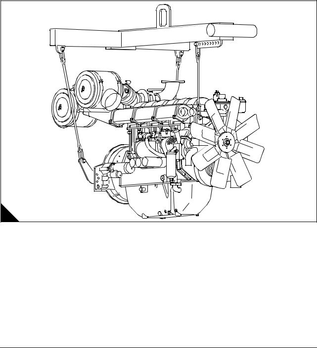
Engine lift equipment |
|
When lifting engine or generating sets, special lifting equipment is required. It is recommended that a spreader lifting beam of the correct lifting load capacity is used and that chains, hooks, shackles and eye bolts etc. are checked that they are well within their safe working loads. The load should be secure, stable and balanced when lifting.
The lifting chains etc must be firmly secured to the load by means of hooks etc on to the purpose-designed lifting points, and that included angle is not exceeded (A).
In order to accommodate the chains for lifting it may be necessary to have to remove engine components such as air filters etc to prevent damage, but this should be avoided where the chains can be clear by nondetrimental means.
Warning! Lifting equipment should be used by trained personnel only. Generating sets must be lifted using the lifting lugs on the engine frame and a spreader lifting beam. The engine lifting brackets and alternator lifting lugs must not be used.
A |
D1144 |
6 |
Workshop Manual, TPD 1511E, issue 1 |

4000 Series |
1 |
POWERPART recommended consumable products |
|
Perkins have made available the products recommended below in order to assist in the correct operation, service and maintenance of your engine and your machine. The instructions for the use of each product are given on the outside of each container. These products are available from your Perkins distributor.
POWERPART ELC (Extended Life Coolant).
ELC is pre-mixed and protects the cooling system against frost and corrosion. Part number 21820181.(1)
POWERPART Easy flush
Cleans the cooling system. Part number 21825001.
POWERPART Gasket and flange sealant
To seal flat faces of components where no joint is used. Especially suitable for aluminium components. Part number 21820518.
POWERPART Gasket remover
An aerosol for the removal of sealants and adhesives. Part number 21820116.
POWERPART Griptite
To improve the grip of worn tools and fasteners. Part number 21820129.
POWERPART Hydraulic threadseal
To retain and seal pipe connections with fine threads. Especially suitable for hydraulic and pneumatic systems. Part number 21820121.
POWERPART Industrial grade super glue
Instant adhesive designed for metals, plastics and rubbers. Part number 21820125.
POWERPART Lay-Up 1
A diesel fuel additive for protection against corrosion. Part number 1772204.
POWERPART Lay-Up 2
Protects the inside of the engine and of other closed systems. Part number 1762811.
POWERPART Lay-Up 3
Protects outside metal parts. Part number 1734115.
POWERPART Metal repair putty
Designed for external repair of metal and plastic. Part number 21820126.
POWERPART Pipe sealant and sealant primer
To retain and seal pipe connections with coarse threads. Pressure systems can be used immediately. Part number 21820122.
Continued
Workshop Manual, TPD 1511E, issue 1 |
7 |

1 |
4000 Series |
POWERPART Radiator stop leak
For the repair of radiator leaks. Part number 21820127.
POWERPART Retainer (high strength)
To retain components which have an interference fit. Part number 21820638.
POWERPART Retainer (oil tolerant)
To retain components which have an interference fit, but are in contact with oil. Part number 21820608.
POWERPART Safety cleaner
General cleaner in an aerosol container. Part number 21820128.
POWERPART Silicone adhesive
An RTV silicone adhesive for application where low pressure tests occur before the adhesive sets. Used for sealing flange where oil resistance is needed and movement of the joint occurs. Part number 21826038. (2)
POWERPART Silicone RTV sealing and jointing compound
Silicone rubber sealant which prevents leakage through gaps. Part number 1861108. (2)
POWERPART Stud and bearing lock
To provide a heavy duty seal to components that have a light interference fit. Part number 21820119 or 21820120.
POWERPART Threadlock and nutlock
To retain small fasteners where easy removal is necessary. Part number 21820117 or 21820118.
POWERPART Universal jointing compound
Universal jointing compound which seals joints. Part number 1861117.(2)
(1)Powerpart (ELC) is not recommended for the 1300 Series.
(2)These product must not be used for the 4006-23 engine.
8 |
Workshop Manual, TPD 1511E, issue 1 |
4000 Series
2
Specifications
Basic engine data
Number of cylinders. ... ... ... ... ... ... ... ... ... ... ... ... ... ... ... ... ... ... ... ... ... ... ... ... ... ... ... ... ... ... ... ... ... ... 6 Cylinder arrangement .. ... ... ... ... ... ... ... ... ... ... ... ... ... ... ... ... ... ... ... ... ... ... ... ... ... ... ... ...Vertical, in-line Cycle ... ... ... ... ... ... ... ... ... ... ... ... ... ... ... ... ... ... ... ... ... ... ... ... ... ... ... ... ... ... ... ... ... ... ... ... Four stroke Induction system.. ... ... ... ... ... ... ... ... ... ... ... ... ... ... ... .Turbocharged, air cooled C.A. in radiator (air to air) Combustion system . ... ... ... ... ... ... ... ... ... ... ... ... ... ... ... ... ... ... ... ... ... ... ... ... ... ... ... ... ...Direct injection Nominal bore ... ... ... ... ... ... ... ... ... ... ... ... ... ... ... ... ... ... ... ... ... ... ... ... ... ... ... ... ... ... ... ... ... ... . 160 mm Nominal stroke. ... ... ... ... ... ... ... ... ... ... ... ... ... ... ... ... ... ... ... ... ... ... ... ... ... ... ... ... ... ... ... ... ... . 190 mm Compression ratio ... ... ... ... ... ... ... ... ... ... ... ... ... ... ... ... ... ... ... ... ... ... ... ... ... ... ... ... ... ... ... ... ... ... 13:1 Cubic capacity . ... ... ... ... ... ... ... ... ... ... ... ... ... ... ... ... ... ... ... ... ... ... ... ... ... ... ... ... ... ... ... ... .22,92 litres Firing order .. ... ... ... ... ... ... ... ... ... ... ... ... ... ... ... ... ... ... ... ... ... ... ... ... ... ... ... ... ... ... ... ... 1, 5, 3, 6, 2, 4 Direction of rotation . ... ... ... ... ... ... ... ... ... ... ... ... ... ... ... ... ... ... ... ... ... Anti-clockwise viewed on flywheel
Lubricating oil capacity:
Total system ... ... ... ... ... ... ... ... ... ... ... ... ... ... ... ... ... ... ... ... ... ... ... ... ... ... ... ... . 122,7 litres (27 gallons) Sump maximum... ... ... ... ... ... ... ... ... ... ... ... ... ... ... ... ... ... ... ... ... ... ... ... ... ... ... . 113,7 litres (25 gallons) Sump minimum ... ... ... ... ... ... ... ... ... ... ... ... ... ... ... ... ... ... ... ... ... ... ... ... ... ... ... ...90,9 litres (20 gallons)
Lubricating oil pressure:
At rated speed (Min) ... ... ... ... ... ... ... ... ... ... ... ... ... ... ... ... ... ... ... ... ... ... ... ... ... ... ... 200 kPa (29 lb/in2) Typical coolant capacity of engine... ... ... ... ... ... ... ... ... ... ... ... ... ... ... ... ... ... ... ... ... ... 36 litres (8 gallons) Typical coolant capacity of engine and radiator .. ... ... ... ... ... ... ... ... ... ... ... ... ... ... ... 105 litres (23 gallons)
Workshop Manual, TPD 1511E, issue 1 |
9 |

2 |
4000 Series |
Data and dimensions
Rocker assembly
Rocker shaft diameter ... ... ... ... ... ... ... ... ... ... ... ... ... ... ... ... ... ... ... ... ... ... ... ... ... ... 39,975 / 39,950 mm Valve rocker lever bore .. ... ... ... ... ... ... ... ... ... ... ... ... ... ... ... ... ... ... ... ... ... ... ... ... ... 40,025 / 40,000 mm Clearance between valve rocker levers and shaft . ... ... ... ... ... ... ... ... ... ... ... ... ... ... ... ..0,025 to 0,075 mm Unit fuel injector rocker lever bore . ... ... ... ... ... ... ... ... ... ... ... ... ... ... ... ... ... ... ... ... ... 40,025 / 40,000 mm
Valves
Diameter of valve stem .. ... ... ... ... ... ... ... ... ... ... ... ... ... ... ... ... ... ... ... ... ... ... ... ... 11,0236 / 11,0109 mm
Diameter of valve head:
Inlet valve... ... ... ... ... ... ... ... ... ... ... ... ... ... ... ... ... ... ... ... ... ... ... ... ... ... ... ... ... ... ... ... 52,12 / 52,00 mm Exhaust valve. ... ... ... ... ... ... ... ... ... ... ... ... ... ... ... ... ... ... ... ... ... ... ... ... ... ... ... ... ... ... 52,12 / 52,00 mm
Angle of face of valve:
Inlet valve... ... ... ... ... ... ... ... ... ... ... ... ... ... ... ... ... ... ... ... ... ... ... ... ... ... ... ... ... ... ... ... ... 30°30’ / 30°00’ Exhaust valve. ... ... ... ... ... ... ... ... ... ... ... ... ... ... ... ... ... ... ... ... ... ... ... ... ... ... ... ... ... ... ... 30°30’ / 30°00’
Thickness of valve lip:
Inlet valve and exhaust valve. ... ... ... ... ... ... ... ... ... ... ... ... ... ... ... ... ... ... ... ... ... ... ... ... ... ... 2,1 / 1,9 mm Exhaust valve and inlet valve minimum “outside diameter: land” thickness .. ... ... ... ... ... ... ... ... ... ... ... 1 mm
Length of valve:
Inlet ... ... ... ... ... ... ... ... ... ... ... ... ... ... ... ... ... ... ... ... ... ... ... ... ... ... ... ... ... ... ... ... ... ... 170,0 / 169,5 mm Exhaust .. ... ... ... ... ... ... ... ... ... ... ... ... ... ... ... ... ... ... ... ... ... ... ... ... ... ... ... ... ... ... ... ... 170,0 / 169,5 mm
Valve guides
Bore of valve guide when installed ... ... ... ... ... ... ... ... ... ... ... ... ... ... ... ... ... ... ... ... ... 11,118 / 11,082 mm
Do not use a combination of a valve and valve guide which have a difference of 0,20 mm or more.
Height from cylinder head to top of valve guide. ... ... ... ... ... ... ... ... ... ... ... ... ... ... ... ... ... ... ... ... ... ... 9 mm
Valve springs
Assembled length .. ... ... ... ... ... ... ... ... ... ... ... ... ... ... ... ... ... ... ... ... ... ... ... ... ... ... ... ... ... ... .. 42,545 mm Load at assembled length.. ... ... ... ... ... ... ... ... ... ... ... ... ... ... ... ... ... ... ... ... ... ... ... ... ... ... ... ... ... 399,6 N Minimum operating length.. ... ... ... ... ... ... ... ... ... ... ... ... ... ... ... ... ... ... ... ... ... ... ... ... ... ... ... .. 31,369 mm Load at minimum operating length. ... ... ... ... ... ... ... ... ... ... ... ... ... ... ... ... ... ... ... ... ... ... ... ... ... ... 695,1 N Free length after test.. ... ... ... ... ... ... ... ... ... ... ... ... ... ... ... ... ... ... ... ... ... ... ... ... ... ... ... ... ... ..57,658 mm Outside diameter ... ... ... ... ... ... ... ... ... ... ... ... ... ... ... ... ... ... ... ... ... ... ... ... ... ... ... ... ... ... ... .. 33,934 mm Minimum free length .. ... ... ... ... ... ... ... ... ... ... ... ... ... ... ... ... ... ... ... ... ... ... ... ... ... ... ... ... ... ... ..55,6 mm
10 |
Workshop Manual, TPD 1511E, issue 1 |
4000 Series |
2 |
Valve seat inserts
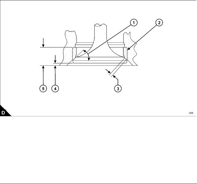
Depth of bore in cylinder head for valve seat insert (A5):
Inlet valve ... ... ... ... ... ... ... ... ... ... ... ... ... ... ... ... ... ... ... ... ... ... ... ... ... ... ... ... ... ... ... .. 11,10 / 11,00 mm Exhaust valve .. ... ... ... ... ... ... ... ... ... ... ... ... ... ... ... ... ... ... ... ... ... ... ... ... ... ... ... ... ... .. 11,10 / 11,00 mm
Diameter of valve seat insert (A2):
Inlet valve ... ... ... ... ... ... ... ... ... ... ... ... ... ... ... ... ... ... ... ... ... ... ... ... ... ... ... ... ... ... .. 56,119 / 56,094 mm Exhaust valve .. ... ... ... ... ... ... ... ... ... ... ... ... ... ... ... ... ... ... ... ... ... ... ... ... ... ... ... ... .. 56,620 / 56,595 mm
Bore in cylinder head for valve seat insert (A2):
Inlet valve ... ... ... ... ... ... ... ... ... ... ... ... ... ... ... ... ... ... ... ... ... ... ... ... ... ... ... ... ... ... ... ... ... ... ..56 mm H7 Exhaust valve .. ... ... ... ... ... ... ... ... ... ... ... ... ... ... ... ... ... ... ... ... ... ... ... ... ... ... ... ... ... ... ... .56,50 mm H7
Angle of face of valve seat insert (A1):
Inlet valve insert... ... ... ... ... ... ... ... ... ... ... ... ... ... ... ... ... ... ... ... ... ... ... ... ... ... ... ... ... ... ...30°30’ / 30°00’ Exhaust valve insert ... ... ... ... ... ... ... ... ... ... ... ... ... ... ... ... ... ... ... ... ... ... ... ... ... ... ... ... ...30°30’ / 30°00’
Valve recess (A4):
Inlet valve (new parts) . ... ... ... ... ... ... ... ... ... ... ... ... ... ... ... ... ... ... ... ... ... ... ... ... ... ... ... ... ... ... ... . Flush Exhaust valve (new parts) ... ... ... ... ... ... ... ... ... ... ... ... ... ... ... ... ... ... ... ... ... ... ... ... ... ... ... ... ... ... . Flush Inlet valve ... ... ... ... ... ... ... ... ... ... ... ... ... ... ... ... ... ... ... ... ... ... ... ... ... ... ... ... ... ... ... ... Maximum: 1 mm Exhaust valve .. ... ... ... ... ... ... ... ... ... ... ... ... ... ... ... ... ... ... ... ... ... ... ... ... ... ... ... ... ... ... Maximum: 1 mm
|
|
|
A |
|
D1366 |
|
|
|
Workshop Manual, TPD 1511E, issue 1 |
11 |
2 |
4000 Series |
Cylinder head
Thickness of cylinder head (new) .. ... ... ... ... ... ... ... ... ... ... ... ... ... ... ... ... ... ... ... ... 140,075 / 139,925 mm Minimum thickness for a used cylinder head . ... ... ... ... ... ... ... ... ... ... ... ... ... ... ... ... ... ... ... ... 139,773 mm
Flatness of cylinder head: The cylinder head flame face must be flat within a maximum of 0,03 mm (0.001 in) with the rocker box face parallel within 0,076 mm.
Piston and connecting rod
Piston ring gaps measured with the ring fitted in a new liner with a bore size: 160,025 / 160,000 mm
Top piston ring ... ... ... ... ... ... ... ... ... ... ... ... ... ... ... ... ... ... ... ... ... ... ... 0,80 mm, maximum worn 1,05 mm Intermediate ring (second) . ... ... ... ... ... ... ... ... ... ... ... ... ... ... ... ... ... ... 0,60 mm, maximum worn 0,85 mm Oil control ring ... ... ... ... ... ... ... ... ... ... ... ... ... ... ... ... ... ... ... ... ... ... ... 0,60 mm, maximum worn 0,85 mm Width of groove for oil control ring in new piston ... ... ... ... ... ... ... ... ... ... ... ... ... ... ... ... ... 6,065 / 6,040 mm Thickness of a new oil control ring. ... ... ... ... ... ... ... ... ... ... ... ... ... ... ... ... ... ... ... ... ... ... 5,990 / 5,975 mm Clearance between piston ring groove and new oil control ring ... ... ... ... ... ... ... ... ... ... ... ... ... ... ... ... ... ...
Maximum permissible clearance between piston
ring groove and a used oil control ring... ... ... ... ... ... ... ... ... ... ... ... ... ... ... ... ... ... ... ... ... ... ... ... 0,254 mm Piston gudgeon pin bore ... ... ... ... ... ... ... ... ... ... ... ... ... ... ... ... ... ... ... ... ... ... ... ... ... 63.525 / 63,515 mm Gudgeon pin diameter ... ... ... ... ... ... ... ... ... ... ... ... ... ... ... ... ... ... ... ... ... ... ... ... ... ... 63,500 / 63,492 mm Length of gudgeon pin ... ... ... ... ... ... ... ... ... ... ... ... ... ... ... ... ... ... ... ... ... ... ... ... ... ... 135,00 / 134,75 mm Bore in connecting rod for small end bearing ... ... ... ... ... ... ... ... ... ... ... ... ... ... ... ... ... 71,450 / 71,425 mm Bore of connecting rod small end bearing . ... ... ... ... ... ... ... ... ... ... ... ... ... ... ... ... ... ... 63,576 / 63,551 mm Bore in connecting rod for big end bearing shells.. ... ... ... ... ... ... ... ... ... ... ... ... ... ... 123,025 / 123,000 mm Distance between centres of big and small end bearings.. ... ... ... ... ... ... ... ... ... ... ... ... 336,06 / 335,94 mm Maximum worn clearance small end.. ... ... ... ... ... ... ... ... ... ... ... ... ... ... ... ... ... ... ... ... ... ... ... ... .. 0,15 mm Conrod end float ... ... ... ... ... ... ... ... ... ... ... ... ... ... ... ... ... ... ... ... ... ... ... ... ... ... ... ... ... ... 0,16 / 0,36 mm
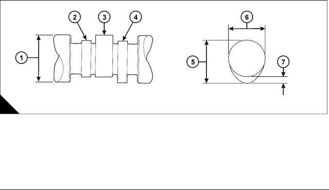
Camshaft and bearings
Diameter of camshaft journal (A3) . ... ... ... ... ... ... ... ... ... ... ... ... ... ... ... ... ... ... ... ... ... 91,960 / 91,933 mm Exhaust cam height (A5) ... ... ... ... ... ... ... ... ... ... ... ... ... ... ... ... ... ... ... ... 78,58 mm, service limit 78,1 mm Inlet cam height (A5).. ... ... ... ... ... ... ... ... ... ... ... ... ... ... ... ... ... ... ... ... ... 78,58 mm, service limit 78,1 mm Injector cam height. ... ... ... ... ... ... ... ... ... ... ... ... ... ... ... ... ... ... ... ... ... ... 78,88 mm, service limit 78,4 mm Maximum: worn clearance cam journal / bearing .. ... ... ... ... ... ... ... ... ... ... ... ... ... ... ... ... ... ... ... ..0,25 mm Camshaft end float. ... ... ... ... ... ... ... ... ... ... ... ... ... ... .0,10 / 0,25 mm, maximum: worn clearance 0,30 mm Cam follower lever assembly:
followers, pivot shaft / arms / shims end float ... ... ... ... ... ... ... ... ... ... ... ... ... ... ... ... ... ... ... 0,50 / 0,25 mm
A |
D1365 |
|
12 |
Workshop Manual, TPD 1511E, issue 1 |
4000 Series |
2 |
Crankshaft, main bearings and flywheel
Diameter of main bearing journal (A3). ... ... ... ... ... ... ... ... ... ... ... ... ... ... ... ... ... ... ... .. 120,59 / 120,57 mm Undersize bearings by . ... ... ... ... ... ... ... ... ... ... ... ... ... ... ... ... ... ... ... ... ... ... ... ... ... ... ... ... ... .. 0,254 mm Undersize bearings by . ... ... ... ... ... ... ... ... ... ... ... ... ... ... ... ... ... ... ... ... ... ... ... ... ... ... ... ... ... .. 0,508 mm Clearance between a new bearing and the journal . ... ... ... ... ... ... ... ... ... ... ... ... ... ... ... .. 0,152 / 0,089 mm Maximum permissible clearance between the
bearing and journal.. ... ... ... ... ... ... ... ... ... ... ... ... ... ... ... ... ... ... ... ... ... ... ... ... ... ... ... ... ... ... .. 0,203 mm Diameter of main bearing bore ... ... ... ... ... ... ... ... ... ... ... ... ... ... ... ... ... ... ... ... ... .. 120,726 / 120,675 mm Diameter of connecting rod journal (A2).. ... ... ... ... ... ... ... ... ... ... ... ... ... ... ... ... ... .. 118,013 / 117,993 mm Undersize bearings by . ... ... ... ... ... ... ... ... ... ... ... ... ... ... ... ... ... ... ... ... ... ... ... .. 0,254 mm and 0.508 mm Clearance between a new bearing and the journal . ... ... ... ... ... ... ... ... ... ... ... ... ... ... ... .. 0,127 / 0,073 mm Maximum permissible clearance between the
bearing and journal.. ... ... ... ... ... ... ... ... ... ... ... ... ... ... ... ... ... ... ... ... ... ... ... ... ... ... ... ... ... ... .. 0,203 mm End-float of crankshaft. ... ... ... ... ... ... ... ... ... ... ... ... ... ... ... ... ... ... ... ... ... ... ... ... ... ... ... .. 0,48 / 0,13 mm Maximum permissible end-float (with used bearings) . ... ... ... ... ... ... ... ... ... ... ... ... ... ... ... ... ... ... 0,53 mm Protrusion of dowel (A1) .. ... ... ... ... ... ... ... ... ... ... ... ... ... ... ... ... ... ... ... ... ... ... ... ... ... ... ... ... ... ... 10 mm
|
3 |
1 |
|
|
|
|
|
2 |
A |
|
D1364 |
Crankcase and cylinder liners
Distance from top of crankcase to centre of main
bearing bore ... ... ... ... ... ... ... ... ... ... ... ... ... ... ... ... ... ... ... ... ... ... ... ... ... ... ... ... ... .. 540,15 / 540,00 mm Block cylinder bore depth (for liner flange) .. ... ... ... ... ... ... ... ... ... ... ... ... ... ... ... ... ... ... .. 15,20 / 15,12 mm Distance from bottom of crankcase to centre of main
bearing bore ... ... ... ... ... ... ... ... ... ... ... ... ... ... ... ... ... ... ... ... ... ... ... ... ... ... ... ... .. 152,425 / 152,375 mm Bore in new cylinder liner ... ... ... ... ... ... ... ... ... ... ... ... ... ... ... ... ... ... ... ... ... ... ... .. 160,025 / 160,000 mm Thickness of liner flange.. ... ... ... ... ... ... ... ... ... ... ... ... ... ... ... ... ... ... ... ... ... ... ... ... ... .. 13,05 / 13,00 mm
Workshop Manual, TPD 1511E, issue 1 |
13 |

2 |
4000 Series |
Lubricating oil pump
Diameter of shaft ... ... ... ... ... ... ... ... ... ... ... ... ... ... ... ... ... ... ... ... ... ... ... ... ... ... ... ... 41,913 / 41,888 mm Diameter of bores in bearing bushes for shaft ... ... ... ... ... ... ... ... ... ... ... ... ... ... ... ... ... 42,039 / 41,974 mm Length of rotors.. ... ... ... ... ... ... ... ... ... ... ... ... ... ... ... ... ... ... ... ... ... ... ... ... ... ... ... ... 50,800 / 50,775 mm Depth of bores for rotors ... ... ... ... ... ... ... ... ... ... ... ... ... ... ... ... ... ... ... ... ... ... ... ... ... ... 50,76 / 50,72 mm Joint O.P. body to cover. ... ... ... ... ... ... ... ... ... ... ... ... ... ... ... ... ... ... ... ... ... ... ... ... ... ... ... ... ... .. 0,25 mm
Spring:
Spring rate . ... ... ... ... ... ... ... ... ... ... ... ... ... ... ... ... ... ... ... ... ... ... ... ... ... ... ... ... ... ... ... ... ... . 1,32 kg/mm Load at 51 mm length ... ... ... ... ... ... ... ... ... ... ... ... ... ... ... ... ... ... ... ... ... ... ... ... ... ... ... ... ... ... ... ... 30 kg Load under 30 mm comp: to assembly length ... ... ... ... ... ... ... ... ... ... ... ... ... ... ... ... ... ... ... ... ... ... 39,6 kg Free length. ... ... ... ... ... ... ... ... ... ... ... ... ... ... ... ... ... ... ... ... ... ... ... ... ... ... ... ... ... ... ... ... ... ... ..73,6 mm Outside diameter ... ... ... ... ... ... ... ... ... ... ... ... ... ... ... ... ... ... ... ... ... ... ... ... ... ... ... ... ... ... ... ... ..24,6 mm Spring plunger bore ... ... ... ... ... ... ... ... ... ... ... ... ... ... ... ... ... ... ... ... ... ... ... ... ... ... ... ... ... ... ... ..25,4 mm
Coolant pump
Shaft diameter at the position of the coolant seal .. ... ... ... ... ... ... ... ... ... ... ... ... ... ... ... 25,095 / 25,087 mm
Gear train
Idler gear end float . ... ... ... ... ... ... ... ... ... ... ... ... ... ... ... ... ... ... ... ... ... ... ... ... ... ... ... ... ... ... 0,2 / 0,1 mm Idler gear maximum: worn . ... ... ... ... ... ... ... ... ... ... ... ... ... ... ... ... ... ... ... ... ... ... ... ... ... ... ... ... ..0,25 mm
Backlash:
Idler, camshaft, oil pump gears.. ... ... ... ... ... ... ... ... ... ... ... ... ... ... ... ... ... ... ... ... ... ... ... 0,375 / 0,125 mm Maximum: worn.. ... ... ... ... ... ... ... ... ... ... ... ... ... ... ... ... ... ... ... ... ... ... ... ... ... ... ... ... ... ... ... ... ... 0,5 mm
Water pump gear in mesh.. ... ... ... ... ... ... ... ... ... ... ... ... ... ... ... ... ... ... ... ... ... ... ... ... ... 0,294 / 0,152 mm
14 |
Workshop Manual, TPD 1511E, issue 1 |

4000 Series |
|
|
|
|
2 |
Torque data |
|
|
|
|
|
|
|
|
|
|
|
Description |
Thread size |
|
Torque |
|
|
|
|
|
|
||
Nm |
|
lbf ft |
kgf m |
||
|
|
|
|||
|
|
|
|
|
|
Crankcase and crankshaft |
|
|
|
|
|
|
|
|
|
|
|
Sump bolts into crankcase |
M10 |
54 |
|
40 |
5,5 |
|
|
|
|
|
|
Sump bolts into gearcase (aluminium) |
M10 |
40 |
|
30 |
4 |
|
|
|
|
|
|
Main bearing cap bolts |
|
See Operation 5-6 |
|
|
|
|
|
|
|
|
|
Main bearing cap side capscrews |
M16 |
n/a |
|
n/a |
n/a |
|
|
|
|
|
|
Oil feed block bolts |
M10 |
27 |
|
20 |
2,7 |
|
|
|
|
|
|
Connecting rod bolts |
|
See Operation 4-2 |
|
|
|
|
|
|
|
|
|
Piston cooling jet bolts |
M10 |
27 |
|
20 |
2,7 |
|
|
|
|
|
|
Camshaft |
|
|
|
|
|
|
|
|
|
|
|
Camshaft gear bolts |
M12 |
150 |
|
110 |
15,2 |
|
|
|
|
|
|
Camshaft thrust plate bolts |
M10 |
50 |
|
35 |
5,1 |
|
|
|
|
|
|
Idler gear hub bolts |
M10 |
50 |
|
35 |
5,1 |
|
|
|
|
|
|
Engine feet bolts |
M10 |
50 |
|
35 |
5,1 |
|
|
|
|
|
|
Cylinder head |
|
|
|
|
|
|
|
|
|
|
|
Cylinder head bolts (Factory Fitted) |
|
175 + 120° |
|
130 + |
17,8 + 120° |
|
|
120° |
|||
|
|
|
|
|
|
|
|
|
|
|
|
Cylinder head bolts (Waisted) - head marked ‘W’ |
M24 |
720 |
|
530 |
73,4 |
|
|
|
|
|
|
General |
|
|
|
|
|
|
|
|
|
|
|
M20 - Grade 8.8 steel bolts to BS3692 |
M20 |
400 |
|
290 |
40,7 |
|
|
|
|
|
|
M16 - Grade 8.8 steel bolts to BS3692 |
M16 |
210 |
|
150 |
21,4 |
|
|
|
|
|
|
M12 - Grade 8.8 steel bolts to BS3692 |
M12 |
85 |
|
60 |
8,6 |
|
|
|
|
|
|
M10 - Grade 12.9 steel bolts to BS3692 |
M10 |
70 |
|
50 |
7,1 |
|
|
|
|
|
|
M10 - Grade 8.8 steel bolts to BS3692 |
M10 |
50 |
|
35 |
5,1 |
|
|
|
|
|
|
M8 - Grade 8.8 steel bolts to BS3692 |
M8 |
25 |
|
18 |
2,5 |
|
|
|
|
|
|
M6 - Grade 8.8 steel bolts to BS3692 |
M6 |
10 |
|
7 |
1,0 |
|
|
|
|
|
|
M6 - Grade 12.9 steel capscrews to BS4168: Part 1 |
M6 |
16 |
|
12 |
1,6 |
|
|
|
|
|
|
M5 - Grade 12.9 steel capscrew to BS4168: Part 1 |
M5 |
13 |
|
10 |
1,3 |
|
|
|
|
|
|
3/8” UNF |
|
40 |
|
30 |
4 |
|
|
|
|
|
|
5/8” UNF |
|
200 |
|
150 |
20,3 |
|
|
|
|
|
|
1/2” UNC |
|
90 |
|
68 |
9,1 |
|
|
|
|
|
|
7/16” UNF |
|
66 |
|
50 |
6,7 |
|
|
|
|
|
|
5/16” UNF |
|
22 |
|
16 |
2,2 |
|
|
|
|
|
|
Starter motors |
M12 |
95 |
|
70 |
7,1 |
|
|
|
|
|
|
Alternator nut |
M24 |
75 |
|
55 |
7,6 |
|
|
|
|
|
|
Taper lockbush |
M8 |
20 |
|
15 |
2 |
|
|
|
|
|
|
Fuel pipes |
|
50 |
|
35 |
5,1 |
|
|
|
|
|
|
Workshop Manual, TPD 1511E, issue 1 |
15 |

2 |
|
|
4000 Series |
||
Main build |
|
|
|
|
|
|
|
|
|
|
|
Description |
Thread size |
|
Torque |
|
|
|
|
|
|
||
Nm |
lbf ft |
kgf m |
|
||
|
|
|
|||
|
|
|
|
|
|
Camshaft |
|
|
|
|
|
|
|
|
|
|
|
Cam follower housing bolts |
M10 |
50 |
35 |
5,1 |
|
|
|
|
|
|
|
Cylinder head |
|
|
|
|
|
|
|
|
|
|
|
Rocker box bolts-graphite joint |
M10 |
70 |
50 |
7,1 |
|
|
|
|
|
|
|
Exhaust manifold to head bolts (Durlock) |
M10 |
70 |
50 |
7,1 |
|
|
|
|
|
|
|
Bridge piece adjuster nubs |
M10 |
35 |
25 |
3,5 |
|
|
|
|
|
|
|
Fuel injector clamp capscrews |
M12 |
95 |
70 |
9,6 |
|
|
|
|
|
|
|
Rocker shaft capscrew/nuts |
M16 |
240 |
180 |
24,9 |
|
|
|
|
|
|
|
Rocker adjuster nuts |
M12 |
50 |
35 |
5,1 |
|
|
|
|
|
|
|
Unit-fuel injector rocker adjuster nuts |
M14 |
70 |
50 |
7,1 |
|
|
|
|
|
|
|
Rocker cover - plastic |
M10 |
4 |
3 |
0,4 |
|
|
|
|
|
|
|
Water pump and oil pump |
|
|
|
|
|
|
|
|
|
|
|
Water pump to gearcase bolts |
M10 |
50 |
35 |
5,1 |
|
|
|
|
|
|
|
Water header to oil cooler bolts |
M10 |
50 |
35 |
5,1 |
|
|
|
|
|
|
|
Crankcase and crankshaft |
|
|
|
|
|
|
|
|
|
|
|
Flywheel bolts (Final torque) |
See Chapter 13, Flywheel and housing |
|
|
||
|
|
|
|
||
T.V. damper bolts (Final torque) |
See Chapter 13, Flywheel and housing |
|
|
||
|
|
|
|
|
|
Front crankshaft pulley assembly |
M16 |
340 |
250 |
34,6 |
|
|
|
|
|
|
|
Unit-fuel injector control linkage |
|
|
|
|
|
|
|
|
|
|
|
Capscrews, unit-fuel injector control lever |
M5 |
8 |
6 |
0,8 |
|
|
|
|
|
|
|
Locknut - control linkage |
M5 |
8 |
6 |
0,8 |
|
|
|
|
|
|
|
Exhaust bellows |
|
|
|
|
|
|
|
|
|
|
|
Bolts / locknuts (torque prevailing) |
M10 |
58 |
43 |
|
|
|
|
|
|
|
|
Durlock bolts / locknuts |
M10 |
70 |
50 |
|
|
|
|
|
|
|
|
Setscrews |
M10 |
50 |
35 |
5,1 |
|
|
|
|
|
|
|
Unitfuel injectors |
|
|
|
|
|
|
|
|
|
|
|
Nuts, fuel injector nozzle to nozzle holder |
M27 |
205 |
150 |
5,9 |
|
|
|
|
|
|
|
Capscrews, fuel injector clamp to cylinder head |
M12 |
95 |
70 |
9,6 |
|
|
|
|
|
|
|
Clips and clamps |
|
|
|
|
|
|
|
|
|
|
|
Hose clips |
|
5 |
3,5 |
0,5 |
|
|
|
|
|
|
|
V-band clamps (Mitsubishi) |
|
9,5 |
7 |
0,96 |
|
|
|
|
|
|
|
16 |
Workshop Manual, TPD 1511E, issue 1 |

4000 Series
3
Cylinder head assembly
General description
Note: In the event of failure, valve or valve seat recession reaching the recommended limit, or when the engine is being overhauled, service exchange cylinder heads supplied by your Perkins Dealer/Distributor are recommended. The specialised equipment and liquid nitrogen are not generally available
The cast iron cylinder heads are fastened to the crankcase by flange head bolts and hardened washers. The cylinder head gasket to crankcase consists of a stainless steel flame ring. The individual inlet and exhaust ports are designed to assist and improve air flow. The ports for the inlet are on the right hand side of the engine and the ports for the exhaust are on the left hand side of the engine.
The cylinder head assembly has four overhead valves for each cylinder. Each valve is held in place by a single coil spring, cap and two collets. The cylinder head has valve seat inserts fitted for both the intake and the exhaust. The intake valve seats are made from high speed steel casting and the exhaust valve seats are made from Pleuco PL12 MV400 which both can be renewed. The valves move in cast iron ferrite nitro carburised valve guides which also can be renewed.
The overhead valves are operated by a rocker shaft assembly in the rocker box. The forged steel rocker levers are operated by forged push rods with hardened ball and sockets ends. The rockers and valve gear are lubricated by oil from the drillings in the rocker shaft that receives oil flow from the extruded fuel/oil rail. Tappet adjustment is achieved by adjustment screws and locknuts at the push rod end of each rocker lever.
In a diesel engine there is little carbon deposit and for this reason the number of hours run is no indication of when to overhaul a cylinder head assembly. The factors which indicate when an overhaul is necessary are how easily the engine starts and its general performance.
Workshop Manual, TPD 1511E, issue 1 |
17 |
3 |
|
|
4000 Series |
Rocker box and valve gear |
|
|
|
|
|
|
|
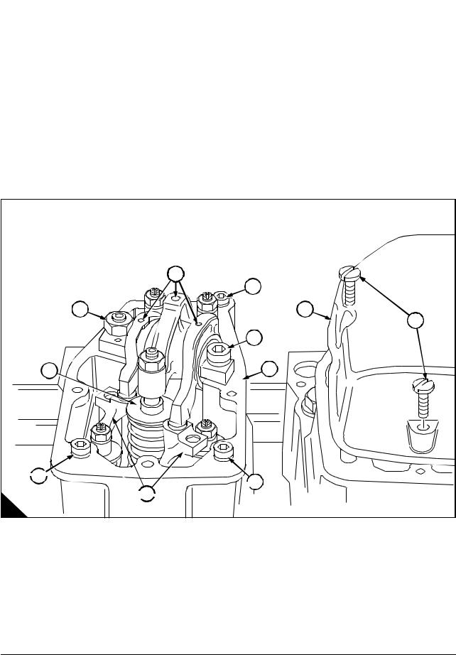
To remove and fit the rocker box and valve gear |
Operation 3-1 |
||
|
|
|
|
Special requirements |
|
|
|
|
|
|
|
Consumable products |
|
|
|
|
|
|
|
Description |
Part number |
|
|
|
|
|
|
POWERPART Hydraulic threadseal |
21820121 |
|
|
|
|
|
|
To remove
1Remove the retaining screws (A5) and lift off the rocker cover (A4). Remove the rocker cover joint and discard.
2Remove the nut (A11) and the Allen screw (A3) then lift off the rocker assembly (A1), the cup pad (A10), the bridge pieces (A8) and the push rods.
3Remove the retaining Allen screw (A2, A7, A9) and remove the rocker box (A6).
4A light blow with a hide mallet may be needed to free the rocker box from its joint.
|
1 |
|
2 |
11 |
4 |
|
5 |
|
3 |
10 |
6 |
 9
9 
 7
7
 8
8 
A
Continued
18 |
Workshop Manual, TPD 1511E, issue 1 |
 Loading...