

Page 1

Perkins Confidential Green Draft 3.2 Aug 2005
1104D and 1106D Electrical and
Electronic Installation Guide
Draft 3.2
Aug 2005
Page 1 of 92 1104D and 1106D Electronic Application and Installation Guide
Page 2

Perkins Confidential Green Draft 3.2 Aug 2005
Contents
INTRODUCTION AND PURPOSE.....................................................................................................5
APPLICABLE ENGINES ...........................................................................................................................5
ELECTRONIC APPLICATIONS CONTACTS................................................................................................ 5
NEW FEATURES – 3056 TO 1106D COMPARISON ....................................................................... 5
1104C and 1106C Implementation (Tier 2)......................................................................................5
1104D and 1106D Implementation (Tier 3) .....................................................................................5
Reason for Change ...........................................................................................................................5
3126B AND 1106D COMPARISON .....................................................................................................8
3126B Implementation (Tier 2) ........................................................................................................8
1104D and 1106D Implementation (Tier 3) .....................................................................................8
Reason for Change ...........................................................................................................................8
ENGINE COMPONENT OVERVIEW ............................................................................................. 11
Engine Control Module .................................................................................................................. 11
SENSOR DETAILS................................................................................................................................. 11
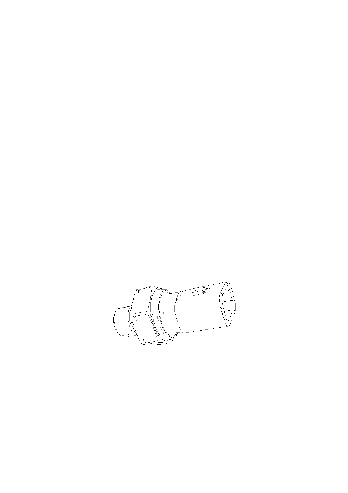
Intake manifold Pressure Sensor purpose ......................................................................................11
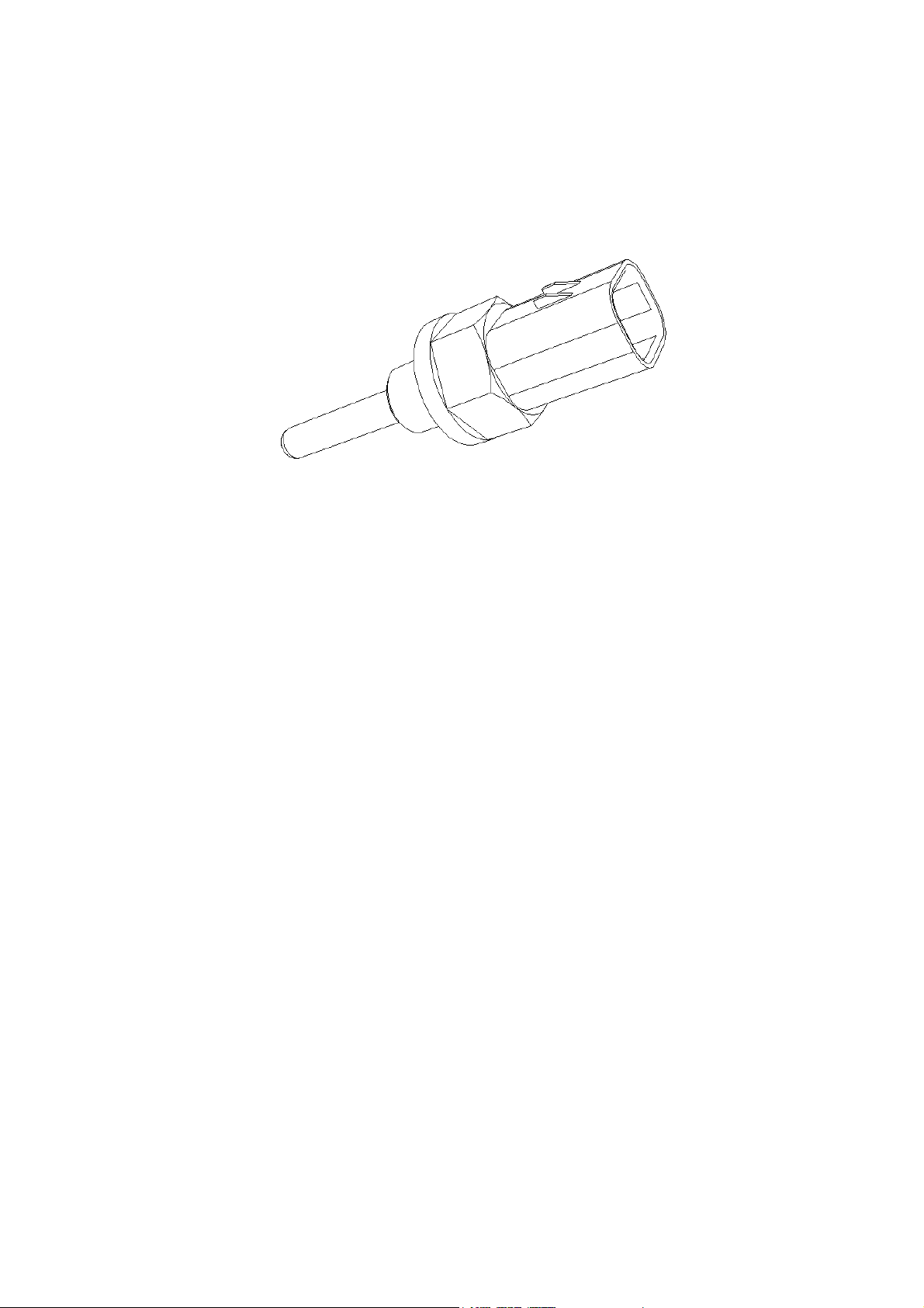
Intake Manifold Temperature Sensor .............................................................................................11
Coolant Temperature Sensor..........................................................................................................12
Fuel Manifold Pressure Sensor ...................................................................................................... 12
Fuel Pump Solenoid .......................................................................................................................13
Fuel Injectors..................................................................................................................................13
Crankshaft Speed/Timing Sensor....................................................................................................13
Pump / Camshaft Speed Sensor......................................................................................................14
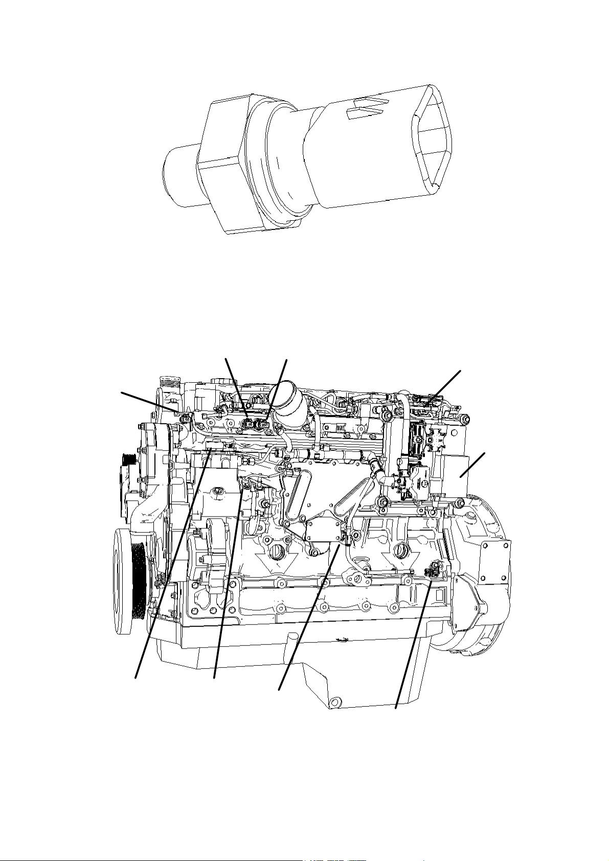
Oil Pressure Sensor........................................................................................................................14
Smart Turbo Wastegate .................................................................................................................. 15
Principal engine electronic components.........................................................................................15
Schematic Diagram of Engine Harness Example OEM Schematic Diagram.................................16
Example OEM Schematic Diagram................................................................................................17
Example 1 Basic Engine Application .............................................................................................17
Example 2 Construction Application..............................................................................................17
Example 3 Industrial Open Power Unit Application......................................................................17
Example 4 Agricultural Application...............................................................................................17
Example 1 - Basic Schematic OEM Harness..................................................................................18
Example 2 - Construction Schematic OEM Harness...................................................................... 19
Example 3 – Industrial Open Power Unit Schematic OEM Harness .............................................20
Example 4 - Agricultural Schematic OEM Harness.......................................................................21
POWER AND GROUNDING RECOMMENDATIONS..................................................................22
ENGINE BLOCK GROUNDING...............................................................................................................22
Ground stud on Starter Motor........................................................................................................ 22
Ground Connection to Tapping on engine Block ........................................................................... 22
ECM BATTERY AND GROUND CONNECTIONS ..................................................................................... 24
VOLTAGE AND CURRENT REQUIREMENTS AND CONSIDERATIONS .......................................................25
Warning – Welding......................................................................................................................... 26
Warning - Electrostatic Paint Spraying .........................................................................................26
Warning – Jump Starting................................................................................................................26
Inductive Energy – Fly-back Suppression Diode ...........................................................................26
CONNECTORS AND WIRING HARNESS REQUIREMENTS.................................................... 28
ECM connector...............................................................................................................................28
Tightening the OEM Connector......................................................................................................28
ECM connector Wire Gauge Size...................................................................................................28
Page 2 of 92 1104D and 1106D Electronic Application and Installation Guide
Page 3

Perkins Confidential Green Draft 3.2 Aug 2005
ECM Connector Terminals.............................................................................................................29
Hand Crimping For Prototype machines and Low Volume Production: ....................................... 29
Machine Crimping For High Volume Production..........................................................................29
Terminal Retention .........................................................................................................................29
ECM connector sealing plug installation guidelines...................................................................... 30
OEM harness Retention at the ECM ..............................................................................................30
HARNESS WIRING STANDARDS ...........................................................................................................31
General Recommendations for Machine Wiring harnesses............................................................31
Connectors......................................................................................................................................31
Cable routing.................................................................................................................................. 31
Mounting location for electronic modules......................................................................................32
Electromagnetic Compliance (EMC) .............................................................................................32
Connector Supplier Contact Details...............................................................................................32
Diagnostic Connector.....................................................................................................................33
Termination Resistor ......................................................................................................................33
Pin Information ..............................................................................................................................33
STOPPING THE ENGINE (AND PREVENTING RESTART) ...................................................... 34
Ignition Keyswitch .......................................................................................................................... 34
Emergency Stop Button ..................................................................................................................34
Battery Isolation Switches ..............................................................................................................35
Remote Stop Button ........................................................................................................................35
Datalink stops................................................................................................................................. 35
Common problems with the application of stop devices.................................................................36
ENGINE SPEED DEMAND................................................................................................................37
ANALOG SENSOR ................................................................................................................................37
Device Description .........................................................................................................................37
Evaluating Component Compatibility ............................................................................................37
Analog Input Test circuit ................................................................................................................ 38
Idle Validation Switch Test Circuit.................................................................................................38
Test Procedure................................................................................................................................38
Required Values..............................................................................................................................39
TEST.................................................................................................................................................... 39
PARAMETER ........................................................................................................................................39
UNITS .................................................................................................................................................. 39
MIN ..................................................................................................................................................... 39
NOMINAL ............................................................................................................................................39
MAX.................................................................................................................................................... 39
Analog Sensors –Connection details ..............................................................................................39
PWM SENSOR - COMPATIBILITY........................................................................................................ 40
Device Description .........................................................................................................................40
Component Compatibility............................................................................................................... 40
Connection details.......................................................................................................................... 40
PTO MODE .......................................................................................................................................... 40
ON/OFF switch ..............................................................................................................................41
Set/lower Button .............................................................................................................................41
Raise/ Resume Button ..................................................................................................................... 41
Disengage Switch ........................................................................................................................... 41
Preset Speed ................................................................................................................................... 41
PTO mode lamp..............................................................................................................................41
Example of PTO mode operation ...................................................................................................42
MULTI POSITION THROTTLE SWITCH (MPTS) ....................................................................................43
TORQUE SPEED CONTROL TSC1 (SPEED CONTROL OVER CAN)........................................................44
ARBITRATION OF SPEED DEMAND........................................................................................................44
Manual Throttle Selection Switch...................................................................................................44
COLD STARTING AID. ..................................................................................................................... 45
Page 3 of 92 1104D and 1106D Electronic Application and Installation Guide
Page 4

Perkins Confidential Green Draft 3.2 Aug 2005
Control of Glow Plugs by the Engine ECM....................................................................................45
Relay, Fuse and Cable Gauge Specification ..................................................................................45
Wait-to-Start / Start Aid active lamps.............................................................................................45
OEM / Operator control or override of the Glow Plugs ................................................................46
Ether Cold Start Systems................................................................................................................ 46
OPERATOR DISPLAYS.....................................................................................................................47
Gauge Drivers ................................................................................................................................47
Lamp Outputs ................................................................................................................................. 47
Indicator lamps Logic.....................................................................................................................48
Datalink Driven Intelligent Displays.............................................................................................. 49
Minimum Functional Specification for J1939 display.................................................................... 49
Customer Triggered Engine Fault codes........................................................................................49
Engine Monitoring System..............................................................................................................50
MONITORED INPUTS FOR CUSTOMER FITTED SENSORS...................................................51
Configurable States ........................................................................................................................51
Air Filter Service Indicator – Air Intake Restriction Switch ..........................................................52
Coolant Low Level Switch .............................................................................................................. 52
Fuel in Water Trap Switch..............................................................................................................52
ENGINE GOVERNOR........................................................................................................................ 53
All speed ......................................................................................................................................... 53
Torque limit curve .......................................................................................................................... 53
Droop..............................................................................................................................................53
High Speed Governor (Governor Run-Out) ...................................................................................53
AUXILLARY GOVERNOR......................................................................................................................55
RATING SELECTION VIA SERVICE TOOL............................................................................................... 55
MODE SWITCHES................................................................................................................................. 55
Rating and Droop changes requested via the J1939 datalink........................................................ 56
VARIABLE SPEED FAN....................................................................................................................57
MACHINE SECURITY SYSTEM ..................................................................................................... 57
USING THE ET SERVICE TOOL. ...................................................................................................57
DATALINK SUPPORT.......................................................................................................................58
SAE J1939..........................................................................................................................................58
Summary of Key J1939 Application Issues.....................................................................................58
Physical layer ................................................................................................................................. 58
Network Layer ................................................................................................................................58
Application Layer ...........................................................................................................................58
J1939 SUPPORTED PARAMETERS QUICK REFERENCE SUMMARYTABLE ..............................................60
RECEIVE / TRANSMIT .....................................................................................................................60
J1939 PARAMETERS – DETAILED DESCRIPTIONS..................................................................64
Section 73 - Diagnostic Layer ...................................................................................................... 80
Supported Parameters – Section 21 - Detailed Descriptions .........................................................83
Supported Parameters – Section 81 Network Management - Detailed Descriptions.....................83
PERKINS DATA LINK ...........................................................................................................................84
OTHER DATALINK STANDARDS........................................................................................................... 84
CANopen ........................................................................................................................................84
OEM Proprietary CAN standards .................................................................................................. 84
LIST OF APPENDICES ...........................................................................................................................84
•
Appendix 1 - ECM J1 Connector Terminal Assignments .......................................................84
•
Appendix 2 – Electronic Options Selection Form...................................................................84
•
Appendix 3 - List of Diagnostic and Event Codes .................................................................84
APPENDIX 1 - ECM J1 CONNECTOR TERMINAL ASSIGNMENTS .......................................................... 85
APPENDIX 2 - ELECTRONIC OPTIONS SELECTION FORM.....................................................................87
APPENDIX 3 – LIST OF DIAGNOSTIC AND EVENT CODES .....................................................................91
Page 4 of 92 1104D and 1106D Electronic Application and Installation Guide
Page 5

Perkins Confidential Green Draft 3.2 Aug 2005
Introduction and Purpose
This document is intended to provide necessary information for correct electrical and
electronic installation of 1104D or 1106D Industrial engine into an off-highway machine.
Perkins Engines Company ltd expects that there will be some additions and modifications to
this document as the engine program development continues, and as OEM requests for
information not currently addressed are added.
The Information herein is the property of Perkins Engines Company ltd Inc. and/or its
subsidiaries. Without written permission, any copying, transmission to others, and any use
except that for which it is loaned is prohibited.
Applicable Engines
This is a draft document, the information contained is the best available at the time of
authoring to describe the application and installation requirements of the production software
as it will be in July 2005.
Some engines shipped before this date will not have all the features described in this
document. Likewise, some additional features will be added after this date. Contact the
Electronic Applications Team for latest information on software feature release dates.
Electronic Applications Contacts
If the information in this document is incomplete, incorrect, or further details are required, then
please contact an Electronic Applications Engineer.
Note that the Contact Details below are valid until Nov 2005
Electronic Applications Team
Oliver Lythgoe
+44 (0)1733 584171
New Features – 3056 to 1106D Comparison
The following table describes the major installation differences between the tier 3 emissions
1104D / 1106D and their predecessors the tier 2 emissions 1104C / 1106C.
1104C and 1106C
Implementation
(Tier 2)
Interface Connector
70 pin Deutsch MIC
connector
ECM power supply
10A fuse, 16AWG wire
(1.5mm2)
Fuel Inject Pump Power Supply
OEM fitted fuel injection
pump power supply relay
1104D and 1106D
Reason for Change
Implementation
(Tier 3)
64 pin Delphi connector –
direct to ECM J1
Connector
25A fuse ECM has higher power requirement, as
No longer required New fuel system does not require
No redundant harness wires. Flexibility
of customer connection
it drivers the injector solenoids
separate power supply
Page 5 of 92 1104D and 1106D Electronic Application and Installation Guide
Page 6

Perkins Confidential Green Draft 3.2 Aug 2005
1104C and 1106C
Implementation
(Tier 2)
Analogue Throttle Position
- New default values for
Cruise control / Set Speed Control / PTO mode
SET / LOWER AND
RAISE / RESUME buttons
were switch to battery type
DISENGAGE feature used
2 switch inputs. The PTO
mode function would
disengage when both
inputs toggled
Coolant Temperature and Oil pressure Gauges
PWM drivers available Drivers not available Gauges not widely used. Low cost and
Tachometer
Frequency driver available Driver not available Low cost and high quality of J1939
Lamp Outputs
2 lamp outputs were used
for cold start, warning,
derate, shutdown and low
oil pressure. A further 1
lamp was available for
PTO mode
CANbus J1939 Shield
Shield connection not
available
1104D and 1106D
Implementation
(Tier 3)
analogue throttle sensors
SET / LOWER AND
RAISE / RESUME
buttons will be switch to
ground type
The DISENGAGE feature
now only requires a
single switch input.
There will be 2 basic
lamp outputs for Orange
(warning) and Red
(shutdown) engine lamps.
Low oil pressure will be
supported by an
additional optional lamp.
The cold start “wait to
start” lamp will be on a
separate lamp, and not
on the Warning lamp as
before
The PTO mode lamp Is
unchanged
Shield connection
available. Connection by
OEM not compulsory
Reason for Change
Easier for OEM’s and component
manufacturers to design and validate
pedals and levels for use with the
engine
Alignment with the PTO mode feature
on larger industrial engines e.g. C9
high quality of J1939 gauges makes
PWM gauges redundant
gauges makes frequency driver
redundant. Also, output from alternator
still provides the function if required.
Splitting the functions onto a greater
number of lamps will make them more
intuitive for the operator.
Connection direct to ECM makes this
connection possible
Page 6 of 92 1104D and 1106D Electronic Application and Installation Guide
Page 7

Perkins Confidential Green Draft 3.2 Aug 2005
1104C and 1106C
Implementation
(Tier 2)
Variable Speed Fan Driver
Fan driver not available Driver available,
Machine Security System
Not available Available at engine
Mode Switch inputs
3 mode switch inputs were
available
Additional Monitoring Capability
Standard engine sensor
monitoring only
J1939 support
Significant changes to
Remote Shutdown
Not supported A single switch input will
1104D and 1106D
Implementation
(Tier 3)
compatible with open
loop hydraulically
controlled fans. .
Provision for future
adding support for
electronically controlled
viscous fans if required
(Check availability)
ordering or as aftermarket
enhancement
(Check availability)
2 mode switch inputs will
be available
Capability to configure
ECM to monitor additional
parameters with OEM
fitted sensors. e.g.
Coolant level, air filter
restriction, Fuel water
trap monitor.
J1939 support:
Some new parameters
added to support new
functions (e.g. change of
rating curve)
Also some parameters
modified
These changes will be
marked in the J1939
section of this document
be available for stopping
the engine. This will be a
normally open switch
which is closed to stop
the engine. Note that this
is not an “Emergency
Stop”
Reason for Change
New ECM has suitable inputs and
outputs to control PWM type fans.
Reduced costs make solution viable
No application has been identified
which requires more than 2 inputs
New feature for added customer value
Additional functions added. Changes to
existing functions made to make
machine integration easier.
New feature
Page 7 of 92 1104D and 1106D Electronic Application and Installation Guide
Page 8

Perkins Confidential Green Draft 3.2 Aug 2005
1104C and 1106C
Implementation
(Tier 2)
Electric Lift Pump Control
Electric Fuel Lift pump on
engine, controlled by the
ECM via an OEM installed
relay
1104D and 1106D
Implementation
(Tier 3)
Mechanical lift pump, so
no relay required to be
fitted by OEM
Reason for Change
Change in fuel pump type
3126B and 1106D Comparison
The higher power range of the 1106D, over the 1106C, means that it may be installed in
some applications that previously used a 3126B (C7). It is also accepted that some personnel
may be more familiar with the Large Power Systems (LPS) industrial products, such as the
C7 and C9, than with the Compact Power Systems (CPS) such as the 1104D and 1106D.
3126B
Implementation
(Tier 2)
Interface Connector
40 pin Deutsch MIC
connector
ECM power supply
15A Fuse 25A Fuse ECM has higher power
Speed Control
The 3126B has a single
throttle control option.
Intermediate Engine Speed Switch
This is a hard-wired
customer configured
speed demand override
between the ranges of Low
Idle and
Top Engine Limit.
1104D and 1106D
Implementation
Reason for Change
(Tier 3)
64 pin Delphi connector –
direct to the ECM J1
Connector
The 1106D electronics is
a newer design with four
throttle customer options.
Not Available This feature is given with added
The additional parameters allows
for extra flexibility of the engine
operation
requirement, as to driver the injector
solenoids, a bigger PSU is needed.
This allows for greater flexibility in
customer choice and application.
functionality in the form of a Multi
Position Switch.
Page 8 of 92 1104D and 1106D Electronic Application and Installation Guide
Page 9

Perkins Confidential Green Draft 3.2 Aug 2005
3126B
Implementation
(Tier 2)
Maintenance Due Reset Switch and Lamp
This switch is used to reset
the counters for the
maintenance indicator.
The lamp shows that
scheduled maintenance is
due.
Torque Limit Switch
This allows the customer
to limit the torque of the
engine between the max
torque and torque at rated
speed.
Mode Switches
Not available. No rating
change during operation
and droop value always
isochronous (0%)
Engine Oil Temperature Sensor
This is a sensor measuring
the oil temperature in the
oil gallery.
Atmospheric Pressure Sensor
This is an absolute
pressure sensor
measuring the
atmospheric pressure.
Auxiliary Pressure Sensor
This allows the customer
to install an auxiliary
pressure sensor.
Auxiliary Temperature Sensor
This allows the customer
to install an auxiliary
temperature sensor.
Coolant Level Sensor
This sensor allows the
ECM to monitor the
coolant level.
Cold Start Aid
Inlet Air Heater with on
board relay and Ether.
1104D and 1106D
Implementation
(Tier 3)
Not Available
Not Available New mode switches offers superior
Mode switches allow for
the active rating and or
droop value to be
changed during engine
operation (to any value
between 0 and 10%)
Not required The fuel injection system on the
Not required Atmospheric pressure is measured
Not Available This is not a feature of the 1106D.
Not Available
Not Available Feature may be added in later
Glow plugs are used with
a customer-supplied relay
are the only cold start aid.
Reason for Change
This is not currently a feature of the
1106D. May be added later over
J1939 datalink
capabilities to perform this function.
New Feature
1104D and 1106D is fuel actuated
rather than oil actuated, and thus
does not require oil temperature
measurement
only at “key on” by Boost pressure
sensor.
This is not a feature of the 1106D.
software release in the form of
configurable I/O.
This is due to the different engine
size and head design. Glow plugs
are more than sufficient on the
1106D
Page 9 of 92 1104D and 1106D Electronic Application and Installation Guide
Page 10

Perkins Confidential Green Draft 3.2 Aug 2005
3126B
Implementation
(Tier 2)
Variable Speed Fan Driver
Not available Compatible with
Air inlet Shutoff Control
In the event of an overspeed, this will shut down
the engine.
Exhaust Brake
This is a method of closing
the exhaust to use the
internal backpressure to
slow the engine down.
1104D and 1106D
Implementation
(Tier 3)
visctronic fans and with
open loop hydraulically
controlled fans. TBA.
Not Available No customer requirement has been
Not Available No customer requirement has been
Reason for Change
New Feature.
identified for off highway engines of
this size
identified for off highway engines of
this size
Page 10 of 92 1104D and 1106D Electronic Application and Installation Guide
Page 11
Perkins Confidential Green Draft 3.2 Aug 2005
Engine Component Overview
Engine Control Module
The A4E2 ECM is located on the left rear side of the engine. The ECM has 2 connectors, one
for the engine harness and the other for the machine OEM harness functionality
The ECM is fuel cooled (see mechanical installation guide for details of fuel connection
requirements)
Sensor Details
Intake manifold Pressure Sensor purpose
The intake manifold pressure signal monitors the air pressure inside the intake manifold, after
the turbo, if fitted. The range is 0-339 Kpa absolute.
The sensor is used to limit fuel preventing black smoke during transient engine conditions,
mainly during acceleration or upon sudden load application. i.e. If intake manifold pressure is
too low for the requested fuel, then the fuel is limited to prevent the overfuel condition.
Intake manifold pressure is also used to control the smart turbo wastegate, if fitted. The
smart wastegate control system regulates intake manifold pressure to the desired value,
calibrated in the software. In order to do this, the software needs to know the actual value of
intake manifold pressure, hence the need for the sensor.
Intake manifold pressure is also used to calculate atmospheric (barometric) pressure.
Atmospheric pressure is used to limit fuel/torque at low atmospheric conditions e.g. at high
altitude fuel may be limited to prevent turbo over-speed.
If the intake manifold pressure sensor/circuit fails, then a low default value is used in the
software. The smart wastegate control (if fitted) will go to open loop, whereby the resultant
intake manifold pressure will be low (as determined by the wastegate hardware chosen) and
hence fuel will be limited under certain engine conditions, effectively providing a fuel/torque
derate.
Intake Pressure Sensor
Intake Manifold Temperature Sensor
This sensor measure the temperature in the inlet air manifold in the range
–40C to +120C.
Note that this is the sensor to which the engine is calibrated. Intake air temperature
measurement is very sensitive to location. If the OEM adds additional inlet air
temperature monitoring, for example during prototype evaluation, it should be
anticipated that there may be a difference of several degrees Celsius between the
engine sensor and the OEM sensor.
Intake manifold temperature is used primarily to determine the cold start strategy.
Page 11 of 92 1104D and 1106D Electronic Application and Installation Guide
Page 12
Perkins Confidential Green Draft 3.2 Aug 2005
The OEM has no connection to this sensor, but if the intake air is required by some machine
system, for example for fan control strategy, then the data can be accessed on the J1939
datalink.
It is possible, if extreme temperatures are measured at the intake that the engine will derate.
In the event of a derate, a fault code will be generated on the J1939 datalink, or displayed on
the service tool, and the warning lamp will light
Temperature Sensor
Coolant Temperature Sensor
The coolant temperature sensor is used for compensating fuel injection control, for activating
the glow plugs for cold engine starting and for detecting excessively high coolant
temperatures for raising an event. The range is –40C to +120C
If the sensor/circuit fails, then a (healthy) high default value is used and a diagnostic code
raised. For glow plug control if this sensor/circuit is faulted, the intake manifold air
temperature sensor is used. It is possible that with this sensor/circuit in a failure condition
white smoke may result during a cold engine start. The Excessive Coolant Temperature
event will not be raised under this fault condition.
The sensor reading of coolant temperature is also used to determine the maximum fuel
allowed during engine starting. If the sensor/circuit fails, it is possible the engine will not start
under cold engine conditions.
It is possible, if the coolant temperature exceeds the design limits, that the engine will derate.
In the event of a derate, a fault code will be generated on the J1939 datalink, or displayed on
the service tool, and the warning lamp will light
Fuel Manifold Pressure Sensor
The fuel rail pressure sensor is used to measure the fuel pressure in the high-pressure fuel
rail. (The fuel in the fuel rail then feeds all injectors. Injection takes place when each injector is
electrically operated.)
The fuel rail pressure measurement is used in conjunction with the high-pressure fuel pump to
maintain the desired fuel pressure in the common rail. This pressure is determined by engine
calibrations to enable the engine to meet emissions and performance objectives.
If the fuel rail pressure sensor/signal is faulted, a diagnostic code is set with a warning; a
default value used and a 100% engine derate results. The default value for fuel rail pressure
will allow the engine to run in a limp home fashion whereby a known fuel rail pressure will be
controlled within reasonable engine conditions. Emissions compliance cannot be guaranteed
under this fault condition.
Page 12 of 92 1104D and 1106D Electronic Application and Installation Guide
Page 13

Perkins Confidential Green Draft 3.2 Aug 2005
Fuel Pump Solenoid
Fuel Rail Pump Solenoid is used to control the output from the high-pressure fuel pump.
The fuel rail pump solenoid is energized when fuel is required to be pumped into the highpressure fuel rail. Varying the energize time of the solenoid controls the fuel delivery from the
pump. The earlier the solenoid is energized (degrees before TDC), the more fuel is pumped
into the fuel rail.
The solenoid forms part of the fuel rail pressure closed loop control system in conjunction with
the fuel rail pressure sensor, ECM and software. The fuel rail pressure sensor measures the
fuel rail pressure; the signal is processed by the ECM and software and compared to the
desired fuel rail pressure for the given engine operating conditions. The control algorithm then
controls the timing of energising the fuel rail pump solenoid. There is no OEM connection to
this component.
If the fuel rail pump solenoid fails, it is likely that fuel will not be pumped into the fuel rail and
engine shutdown or failed start is expected.
Fuel Injectors
Each fuel injector contains a solenoid to control the quantity of fuel injected. Both positive and
negative wires to each solenoid are wired directly back to the ECM
There is no OEM connection to this component. Voltages of up to 70V are used to drive the
injectors.
Injector cables are of the twisted pair to minimize emissions of electromagnetic noise. By their
nature, however, the signals to the injectors are sharp pulses of relatively high current. The
OEM should ensure that any systems that are sensitive to electromagnetic radiation are not in
proximity to the harness components that lead to the injectors.
Crankshaft Speed/Timing Sensor
The crankshaft speed timing sensor is a Hall Effect Sensor. The sensor works in conjunction
with the timing ring fitted to the engine crankshaft.
The sensor produces a signal as the timing ring/crank rotates past the sensor. The ECM then
uses this signal to calculate engine speed and engine position. The crank speed/timing signal
is used during normal engine running since is more accurate than the signal obtained from
the cam speed/timing sensor.
If the crank speed/timing sensor/signal is lost or faulted, the engine is capable of starting
provided the cam speed/timing signal is healthy. A diagnostic and warning will be raised if the
fault occurs during engine running. A full derate will result since the engine is not then
guaranteed to be emissions compliant due to the accuracy of the cam speed/timing signal.
The diagnostic and derate will not be raised during engine cranking (if fault present), but the
service tool will provide a means to read the condition of the cam and crank speed signals to
aid fault finding.
. The OEM has no connection to this sensor. If the OEM requires accurate engine speed
information then this may be obtained from the SAE J1939 datalink.
Page 13 of 92 1104D and 1106D Electronic Application and Installation Guide
Page 14

Perkins Confidential Green Draft 3.2 Aug 2005
Speed Sensor
Pump / Camshaft Speed Sensor
The camshaft speed/timing sensor works in conjunction with the timing ring fitted inside the
high Pressure fuel pump.
The sensor produces a signal as the timing ring/pump rotates past the sensor. The ECM then
uses this signal to calculate engine speed, engine position and engine cycle. The cam
speed/timing signal is required for determining the correct engine cycle and is also used for
limp-home operation in the event of the crank speed sensor/circuit being faulted/lost.
If the camshaft speed/timing sensor/signal is lost or faulted, the engine will not start (since
engine cycle is not known from the crank signal only), but if the engine is already running, no
engine performance effect will be noticed. A diagnostic and warning will be raised if the fault
occurs during engine running. The diagnostic will not be raised during engine cranking, but
the service tool will provide a means to read the condition of the cam and crank speed signals
to aid fault finding.
Oil Pressure Sensor
The oil pressure sensor measures the engine oil pressure in Kpa. Oil pressure is used for
engine protection, whereby if insufficient oil pressure is measured for a given speed, an event
for low oil pressure would be raised. The low oil pressure threshold is defined as a map
against engine speed. Currently, 2 levels of event are being specified. Level 1 is the least
severe and raises a warning. Level 3 is the most severe and raises a warning, which request
the engine be shutdown. Automatic engine shutdown can be configured for certain
applications, such as Gensets to occur when a level 3 event is raised.
If the oil pressure sensor fails, a diagnostic is raised and a default value is used by the
software, which has been chosen to be a healthy (high) pressure value. It is not possible to
raise an event whilst an oil pressure diagnostic is present.
Page 14 of 92 1104D and 1106D Electronic Application and Installation Guide
Page 15
Perkins Confidential Green Draft 3.2 Aug 2005
Oil Pressure Sensor
Smart Turbo Wastegate
Some engine models will be fitted with a turbocharger with a “smart” wastegate
Principal engine electronic components
Intake
Pressure
Sensor
Coolant
Sensor
Intake Temperature
Fuel Rail
Pressure
Sensor
ECM
Fuel Pump
Solenoid
Pump/Cam
Speed
Sensor
Oil Pressure
Sensor
Crank Speed
Sensor
Page 15 of 92 1104D and 1106D Electronic Application and Installation Guide
Note: Variable
Wastegate Fitted to
Right Hand Side
Page 16
Perkins Confidential Green Draft 3.2 Aug 2005
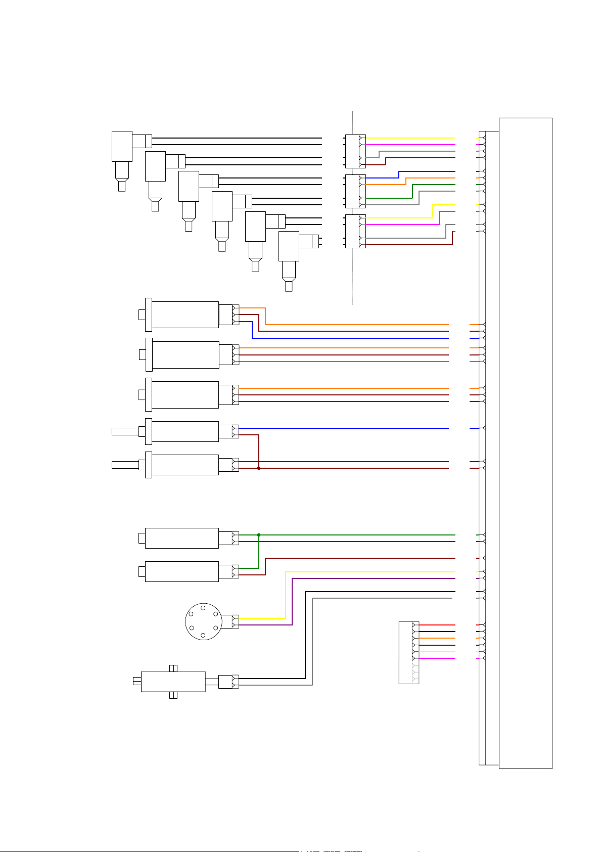
Schematic Diagram of Engine Harness
A4E2 ECM
J2 Connector
INJECTOR
CYLINDER 6
INJECTOR
CYLINDER 5
INJECTOR
CYLINDER 4
INTAKE MANIFOLD
PRESSURE SENSOR
OIL PRESSURE SENSOR
FUEL RAIL PRESSURE
SENSOR
COOLANT TEMPERATURE
SENSOR
INJECTOR
CYLINDER 3
1
2
3
1
2
3
1
2
3
1
2
INJECTOR
CYLINDER 2
INJECTOR
CYLINDER 1
1
T962 BK X931YL
2
T956 BK
T961 BK
T955 BK
T960 BK
T954 BK
T959 BK
T953 BK
T958 BK
T952 BK
T957 BK
T951 BK
INTERNAL
(ROCKER
COVER)
3
4
1
2
3
4
1
2
3
4
EXTERNAL
X925PK
X930 GY
X924 BR
X9929BU
X923 OR
X928 GN
X922 WH
X927 YL
X921 PK
X926 GY
X920 BR
T997 OR
7993 BR
X731 BU
L730 OR
Y947 BR
994 GY
R997 OR
Y948 BR
Y946 BU
995 BU
INJECTOR CYLINDER 6 RE TURN
6
INJECTOR CYLINDER 6
62
INJECTOR CYLINDER 5 RE TURN
7
INJECTOR CYLINDER 5
63
INJECTOR CYLINDER 4 RE TURN
8
INJECTOR CYLINDER 4
64
INJECTOR CYLINDER 3 RE TURN
33
INJECTOR CYLINDER 3
59
INJECTOR CYLINDER 2 RE TURN
34
INJECTOR CYLINDER 2
58
INJECTOR CYLINDER 1 RE TURN
35
INJECTOR CYLINDER 1
57
IMP POWER SUPPLY (5V)
46
IMP RETURN
38
IMP SIGNAL
55
OIL PRESSURE SENSOR PWR (5V)
47
OIL PRESSURE SENSOR RETURN
39
OIL PRESSURE SENSOR SIGNAL
56
FMP SENSOR POWER SUPPLY (5V)
48
FMP SENSOR GROUND
40
FMP SENSOR SIGNAL
51
COOLANT TEMP SIGNAL
43
INTAKE MANIFOLD
TEMPERATURE SENSOR
CRANKSHAFT SPEED/
TIMING SENSOR
PUMP / CAM SPEED
SENSOR
FUEL PUMP
SOLENOID
ELECTRONIC
WASTEGATE
ACTUATOR
1
2
1
2
1
2
1
2
DIAGNOSTIC
CONNECTOR (9 PIN)
1
2
A
B
D
E
F
G
C
H
J
C967 BU
L731 BR
996 GN
E965 BU
P920 BR
Y950 YL
Y951 PU
C211 BK
M795 WH
101 RD
944 OR
945 BR
Y793 YL
Y792 PK
229 BK
IMT SIGNAL
42
TEMPERATURE SENSOR RETURN
37
SPEED SENSOR POWER (8V)
10
CRANK SPEED/TIME SENS SIG
52
PUMP /CAM SPEED SENS SIG
53
FUEL PUMP SOLENOID PWM SIG
25
FUEL PUMP SOLENOID RETURN
26
WASTEGATE RETURN
44
WASTEGATE PWM SIGNAL
17
BAT+ (FOR COMMS ADAPTER)
18
BAT - (FOR COMMS ADAPTER)
45
CDL+
21
CDL-
20
J1939 -
23
J1939 +
24
Page 16 of 92 1104D and 1106D Electronic Application and Installation Guide
Page 17

Perkins Confidential Green Draft 3.2 Aug 2005
Example OEM Schematic Diagram
The engine can be configured and wired many different ways dependant on the requirements
of the OEM. The following four example schematics provide a guide for the OEM
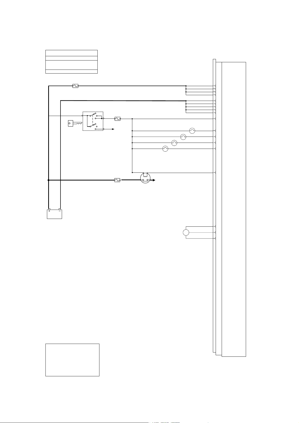
Example 1 Basic Engine Application
This solution is suitable for applications where very little integration or additional engineering
is a requirement when compared to the solution used for a mechanical engine. This solution
can be used in most replacement engine situations. The OEM needs to consider only basic
functions these being Power Supply, Operator Indication, Cold Start Aid and a simple method
of controlling the engine speed.
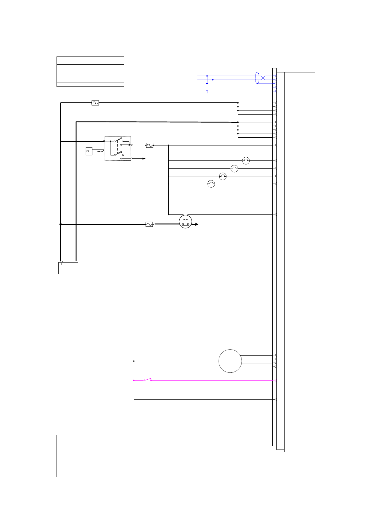
Example 2 Construction Application
An application where the engine, in response to an arrangement of switched inputs will
operate at one of a range of defined speeds. This is suitable for applications where the device
has multiple operating speeds that are either defined for the specific output reasons, for
simplicity of operator use or for operation dependent upon the environment - e.g. quiet
modes. This could include: auxiliary engine on road sweeper, multiple speed water pumps,
etc. There are sixteen possible set speeds based on four discrete ECM inputs. In addition to
the Key-Switch a separate engine shutdown switch is used to stop the engine.
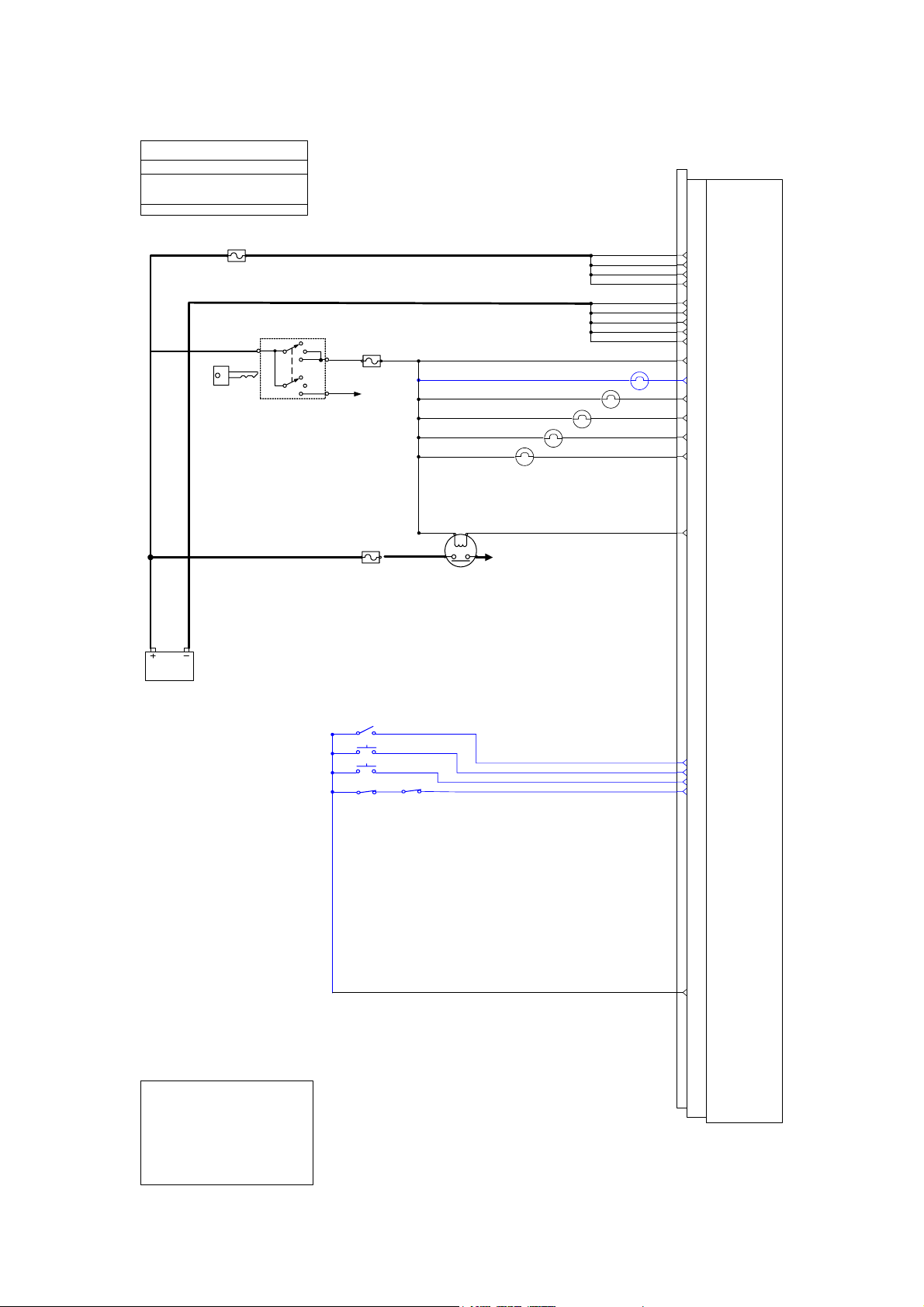
Example 3 Industrial Open Power Unit Application
An application where the engine, in response to a control input, e.g. a button press,
accelerates from idle speed up to the pre-defined operating engine speed. Once at the predefined operating speed, the engine speed may be raised or lowered by increment /
decrement button presses. This is suitable for enhancing some of the applications of the
single speed (set speed) control, or to provide a variable speed control without having a
throttle pedal / lever. This functionality may benefit when the user wants to use ‘set speed
operation’, but with the capability to adjust it themselves - users may have a favorite operating
speed. This could include concrete pumps, hydraulic driven machines.
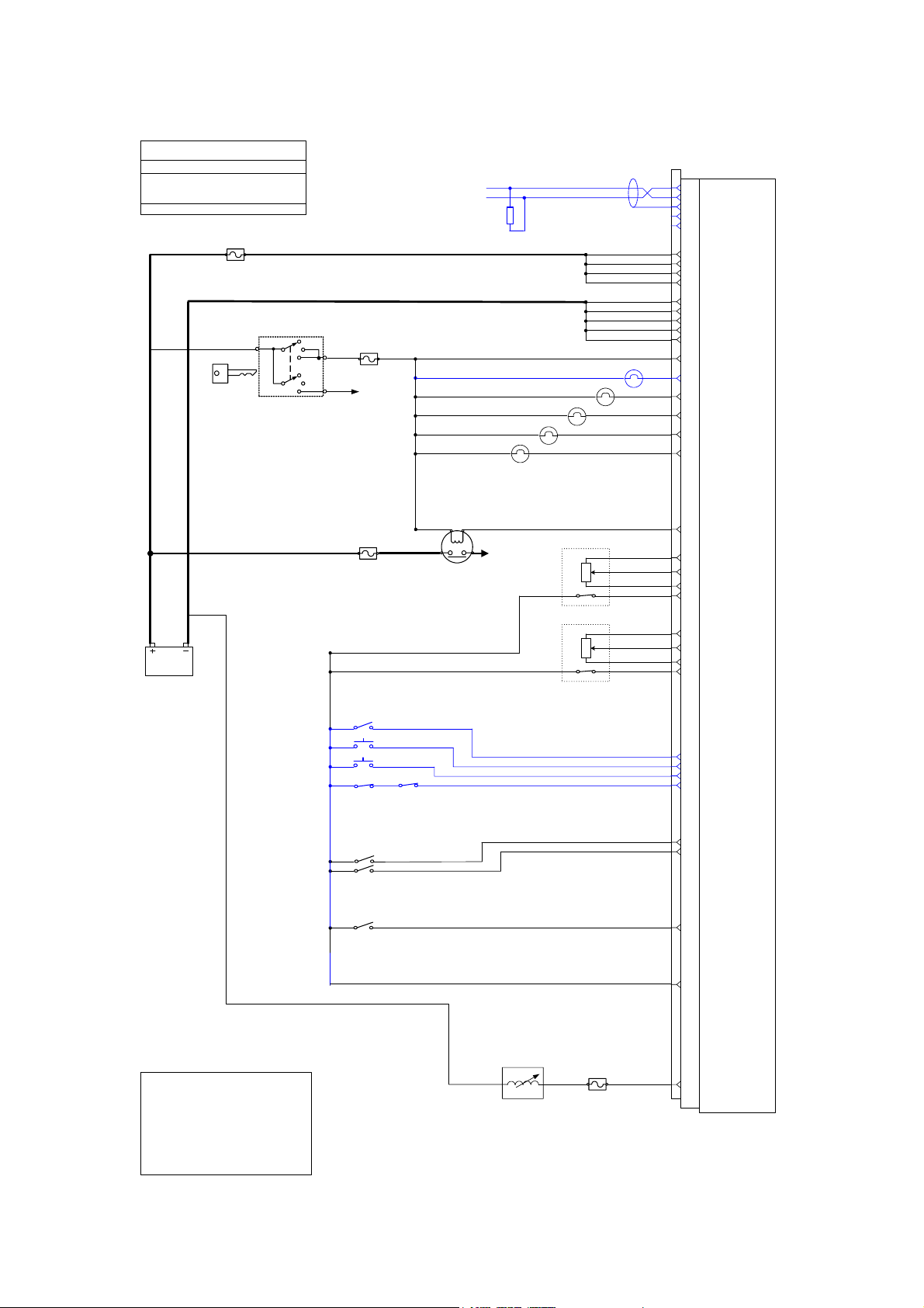
Example 4 Agricultural Application
The application will allow single or twin throttles, engine twin set speed control, Multi mode
operation, integrated display drive, etc. The ECM dependant on engine temperatures varies
the engine-cooling fan.
This set-up is suitable for applications where the customer requires a high degree of operator
control over the machine’s behavior. It is one of the most complex applications. Typically this
is used in mobile applications that may be driven to the place of work and then require
operator selectable speed operation whilst performing their chosen task. This could include:
Tractors, Combines, Backhoe loaders.
Page 17 of 92 1104D and 1106D Electronic Application and Installation Guide
Page 18
Perkins Confidential Green Draft 3.2 Aug 2005
Example 1 - Basic Schematic OEM Harness
Basic OEM Wiring Schematic
Chris Crawford 17 May 2005
UNCONTROLLED DOCUMENT FOR
INDICATION ONLY
Caterpillar Confidential Green
Template file: 1100D series OEM wiring_V05.vsd
A4E2 ECM
J1 CONNECTOR
25A
OFF
ON
STAR
T
IGNITION KEY
SWITCH
12V
5A
TO STARTER MOTOR
SOLENOID (NOTE 2)
50A
LOW OIL PRESSURE
GLOW PLUG
RELAY
WARNING LAMP
COLD START - WAIT TO
START LAMP
LAMP
TO GLOW
PLUGS
PWM
THROTTLE
SENSOR
STOP LAMP
BATTERY +
7
BATTERY +
8
BATTERY +
15
BATTERY +
16
BATTERY -
1
BATTERY -
2
BATTERY -
3
BATTERY -
9
BATTERY -
10
IGNITION KEYSWTICH
40
STOP LAMP
60
WARNING / COLD START LAMP
59
COLD START LAMP (OPTIONAL)
63
LOW OIL PRESSURE LAMP
62
(OPTIONAL)
START AID CONTROL
57
SENSOR SUPPLY 8V
43
PWM THROTTLE SENSOR INPUT
53
SENSOR RETURN
33
1. CAN shield connection at ECM is optional
2. Fuse value depends on Starter motor relay current
3. CDL can be connected OEM wished to fit additional
diagnostic connectors
4. All relays should have suppression diodes fitted accross
the coils
5. Starter motor control circuits will vary
NOTES
Page 18 of 92 1104D and 1106D Electronic Application and Installation Guide
Page 19
Perkins Confidential Green Draft 3.2 Aug 2005
Example 2 - Construction Schematic OEM Harness
Construction OEM Wiring Schematic
Chris Crawford 18 Nov 2004
UNCONTROLLED DOCUMENT FOR
INDICATION ONLY
Caterpillar Confidential Green
Template file: 1100D series OEM w iring_V04.vsd
25A
CAN J1939 BUS
120
OHM
OFF
ON
STAR
T
5A
NOTE 1
NOTE 3
A4E2 ECM
J1 CONNECTOR
CAN J1939 +
20
CAN J1939 -
21
CAN J1939 SHIELD
22
CDL +
23
CDL -
24
BATTERY +
7
BATTERY +
8
BATTERY +
15
BATTERY +
16
BATTERY -
1
BATTERY -
2
BATTERY -
3
BATTERY -
9
BATTERY -
10
IGNITION KEYSWTICH
40
IGNITION KEY
SWITCH
12V
TO STARTER MOTOR
SOLENOID (NOTE 2)
50A
LOW OIL PRESSURE
GLOW PLUG
RELAY
COLD START - WAIT TO
START LAMP
LAMP
TO GLOW
PLUGS
WARNING LAMP
STOP LAMP
STOP LAMP
60
WARNING / COLD START LAMP
59
COLD START LAMP
63
LOW OIL PRESSURE LAMP
62
START AID CONTROL
57
10
POSITION
ROTARY
SWITCH
1. CAN shield connection at ECM is optional
2. Fuse value depends on Starter motor relay c urrent
3. CDL can be connected OEM wished to fit additional
diagnostic connectors
4. All relays should have suppression di odes fitted accross
the coils
5. Starter motor control circuits will vary
NOTES
Page 19 of 92 1104D and 1106D Electronic Application and Installation Guide
THROTTLE POSITION SWITCH 1
52
THROTTLE POSITION SWITCH 2
51
THROTTLE POSITION SWITCH 3
50
THROTTLE POSITION SWITCH 4
49
SHUTDOWN SWITCH (CLOSE TO
48
STOP)
SWITCH RETURN
35
Page 20
Perkins Confidential Green Draft 3.2 Aug 2005
Example 3 – Industrial Open Power Unit Schematic OEM Harness
IOPU OEM Wiring Schematic
Chris Crawford 18 Nov 2004
UNCONTROLLED DOCUMENT FOR
INDICATION ONLY
Caterpillar Confidential Green
Template file: 1100D series OEM w iring_V04.vsd
A4E2 ECM
J1 CONNECTOR
25A
OFF
ON
STAR
T
IGNITION KEY
SWITCH
12V
5A
TO STARTER MOTOR
SOLENOID
50A
LOW OIL PRESSURE
GLOW PLUG
RELAY
WARNING LAMP
COLD START - WAIT TO
START LAMP
LAMP
TO GLOW
PLUGS
PTO MODE LAMP
STOP LAMP
BATTERY +
7
BATTERY +
8
BATTERY +
15
BATTERY +
16
BATTERY -
1
BATTERY -
2
BATTERY -
3
BATTERY -
9
BATTERY -
10
IGNITION KEYSWTICH
40
PTO MODE LAMP
61
STOP LAMP
60
WARNING / COLD START LAMP
59
COLD START LAMP
63
LOW OIL PRESSURE LAMP
62
START AID CONTROL
57
RAISE / RESUME
DISENGAGE SWITCH
1. CAN shield connection at ECM is optional
2. Fuse value depends on Starter motor relay c urrent
3. CDL can be connected OEM wished to fit additional
diagnostic connectors
4. All relays should have suppression di odes fitted accross
the coils
5. Starter motor control circuits will vary
NOTES
ON / OFF
SET / LOWER
PTO MODE - ON / OFF
52
PTO MODE - SET/ LOWER
51
PTO MODE - RAISE /RESUME
50
PTO MODE - DISENGAGE (NC)
49
SWITCH RETURN
35
Page 20 of 92 1104D and 1106D Electronic Application and Installation Guide
Page 21
Perkins Confidential Green Draft 3.2 Aug 2005
Example 4 - Agricultural Schematic OEM Harness
Agricultural OEM Wiring Schematic
Chris Crawford 17 May 2005
UNCONTROLLED DOCUMENT FOR
INDICATION ONLY
Caterpillar Confidential Green
Template file: 1100D series OEM wiring_V04.vsd
25A
IGNITION KEY
SWITCH
OFF
ON
STAR
T
5A
TO STARTER MOTOR
SOLENOID (NOTE 2)
120
OHM
COLD START - WAIT TO
START LAMP
LOW OIL PRESSURE
LAMP
WARNING LAMP
CAN J1939 BUS
PTO MODE LAMP
STOP LAMP
NOTE 1
NOTE 3
A4E2 ECM
J1 CONNECTOR
CAN J1939 +
20
CAN J1939 -
21
CAN J1939 SHIELD
22
CDL +
23
CDL -
24
BATTERY +
7
BATTERY +
8
BATTERY +
15
BATTERY +
16
BATTERY -
1
BATTERY -
2
BATTERY -
3
BATTERY -
9
BATTERY -
10
IGNITION KEYSWTICH
40
PTO MODE LAMP (OPTIONAL)
61
STOP LAMP
60
WARNING / COLD START LAMP
59
COLD START LAMP (OPTIONAL)
63
LOW OIL PRESSURE LAMP
62
(OPTIONAL)
START AID CONTROL
50A
GLOW PLUG
RELAY
12V
ON / OFF
SET / LOWER
RAISE / RESUME
DISENGAGE SWITCH
MODE SWITCH 1
MODE SWITCH 2
THROTTLE SELECTION
SWITCH
TO GLOW
PLUGS
ANALOGUE
THROTTLE
SENSOR 1
ANALOGUE
THROTTLE
SENSOR 2
57
SENSOR SUPPPLY 5V
41
ANALOGUE THROTTLE INPUT 1
54
SENSOR RETURN
33
IDLE VALIDATION (IVS) 1
45
SENSOR SUPPPLY 5V
42
ANALOGUE THROTTLE INPUT 2
55
SENSOR RETURN
34
IDLE VALIDATION (IVS)2
44
PTO MODE - ON / OFF
52
PTO MODE - SET/ LOWER
51
PTO MODE - RAISE /RESUME
50
PTO MODE - DISENGAGE (NC)
49
MODE SWITCH 1
46
MODE SWITCH 2
39
THROTTLE SELECTION SWITCH
47
FAN DRIVE
SOLENOID
1. CAN shield connection at ECM is optional
2. Fuse value depends on Starter motor relay current
3. CDL can be connected OEM wished to fit additional
diagnostic connectors
4. All relays should have suppression diodes fitted accross
the coils
5. Starter motor control circuits will vary
NOTES
2A
Page 21 of 92 1104D and 1106D Electronic Application and Installation Guide
35
32
SWITCH RETURN
PWM OUTPUT (2A)
Page 22

Perkins Confidential Green Draft 3.2 Aug 2005
Power and Grounding Recommendations
Engine Block Grounding
Although the engine electronics are all directly grounded via the ECM connector, it is also
necessary that the engine block be properly grounded to provide a good return path for
components such as Starter Motor, Alternator and cold Start Aids.
Improper grounding results in unreliable electrical circuit paths. Stray electrical currents can
damage mechanical components, and make electronic systems prone to interference. These
problems are often very difficult to diagnose and repair.
There are 2 acceptable methods of grounding the engine.
Ground stud on Starter Motor
If the Starter motor has a grounding stud then this should be used. The ground connection
should be preferably be made directly back to the battery negative terminal.
The starter motor ground path must not include any flanges or joints. Painted surfaces and
flexible mounts in particular must be avoided. Star washers must not be relied upon to make
contact though paint.
The ground cable should be of cross section 67.4 mm² (00 AWG) or greater.
Ground Connection to Tapping on engine Block
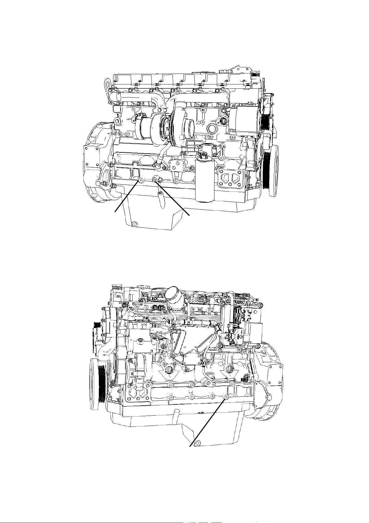
If there is no grounding stud on the Starter motor then a ground cable, direct from the Battery
Negative terminal, should be connected to a ring terminal Which connects to one of the three
tappings shown in diagram 1 and 2. The tapped holes will be reserved for customer use and
can be used for grounding purposes.
If a tapping is used then it should be checked to be free of lacquer, paint and dirt before the
connection is made. A M10 metric screw should be used plated with Zinc. A washer should
retain the ring terminal and the screw tightened to 44 Nm (32Ibft)
It is preferable to use a conductive grease to ensure the reliability of this connection.
Page 22 of 92 1104D and 1106D Electronic Application and Installation Guide
Page 23
Perkins Confidential Green Draft 3.2 Aug 2005
Ground Point
Option 1
Ground Point
Option 2
Diagram 1 Ground Point 1 & 2
Ground Point Option 3
Diagram 2 Ground Point 3
Page 23 of 92 1104D and 1106D Electronic Application and Installation Guide
Page 24
Perkins Confidential Green Draft 3.2 Aug 2005
ECM battery and Ground Connections
The ECM power supply (battery + and battery -) is normally permanently connected to the
machine battery. The exception to this is if the machine is fitted with a battery isolation switch,
which disconnects the battery during storage, transport or maintenance.
When the ignition key switch is off the ECM is in a sleep mode where it draws a very small
residual current. When the ignition key switch is turned on the ECM will become active. It is
recommended, therefore that the ignition keyswitch is turned to the off position when
connecting or disconnecting the ECM J1connector, to prevent large sparks which may cause
damage to the pins.
The power supply to the ECM should be taken from the battery, and not from the starter
motor terminals to avoid unnecessary system noise and voltage drops.
Note that there are 4 ECM pins allocated for battery positive and 5 for battery negative. All 9
pins must be used. It is also necessary to route the battery return via dedicated cable rather
than a return through the machine chassis.
It will normally be necessary to splice the power supply wires from one larger conductor into
the 4 or 5 smaller ones. This splice may be achieved either by a crimped and soldered metal
band (appropriate for low volume manufacture) or by ultrasonic slicing (for medium and high
volume manufacture). All splices should be insulated with adhesive lined heat shrink sleeve.
The Cross Sectional Area of wire on both sides of the splice must be balanced so both sides
fall within the Cross Sectional Area range of the heat shrink sleeve insulator. The distance
between the edge of the splice joint and the wire insulation should be 5.0mm ± 1.5mm.
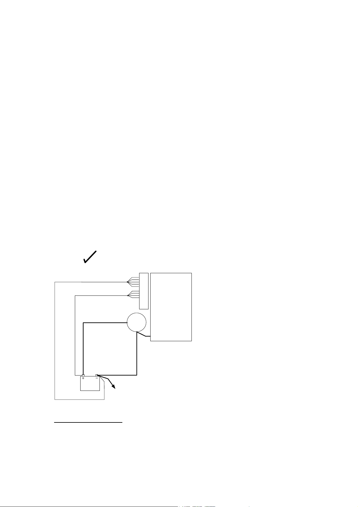
Right
ECM
Connector
Engine
Starter
Motor
Chassis
Correct Power Supply Wiring
• ECM Positive wires connected direct to battery, not via starter motor
• Power supply wires go to all 4 positive pins and all 5 negative pins on the ECM
Connector
• Negative is wired to the battery rather than return through chassis
• The engine is grounded
Page 24 of 92 1104D and 1106D Electronic Application and Installation Guide
Page 25
Perkins Confidential Green Draft 3.2 Aug 2005
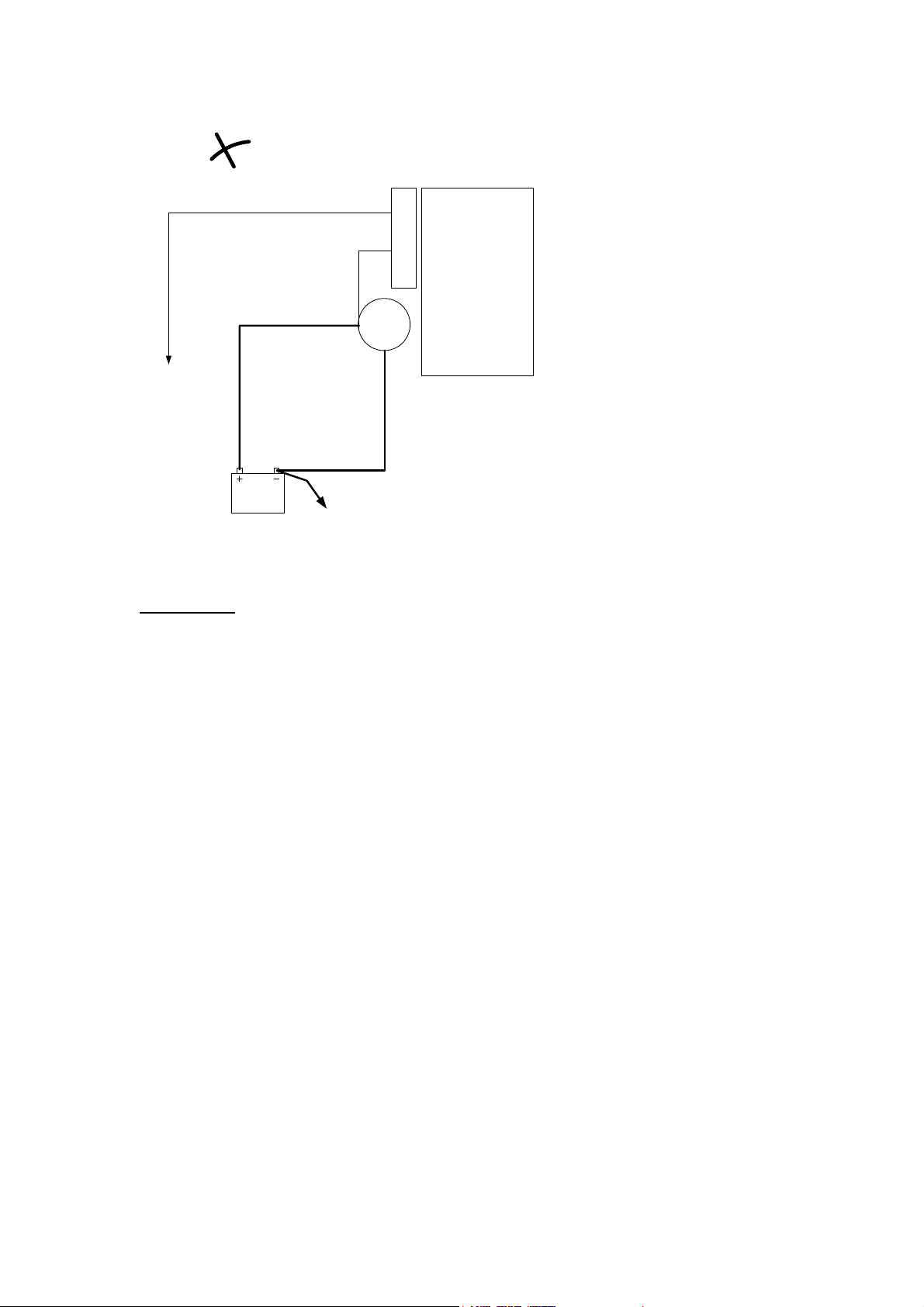
Wrong
Chassis
Chassis
ECM
Connector
Engine
Starter
Motor
Incorrect wiring
• Positive wired via starter motor. High volt drop to ECM on starting
• Single pin on ECM used for each of positive and negative supply. Possibly exceeding
pin ratings and possibly causing risk of arcing or over heating.
• ECM return through chassis – risk of conducted noise and also additional voltage
drop.
• Engine not grounded – risk of engine component damage.
Voltage and Current requirements and considerations
The ECM has an internal switched mode power supply and is thus capable of withstanding
normal low voltage situations, such as occur during starting / cranking. ECM power supply
cables sizes should be selected with care, however to ensure that the average voltage during
cranking is at least 6V at the ECM.
To achieve this, the total resistance of the power supply wiring, including both positive and
negative paths, should not exceed 100mOhms and the voltage at the battery terminals should
not be less than 7.5Volts 2 seconds after the start of cranking.
Information regarding ECM Power Supply requirements is provided in Table 1. Information is
supplied for both 12V and 24V systems. All measurements are based on nominal voltages
expected when the engine is running, 13.8V for 12V systems and 27.8V for 24V systems.
Table 1 - ECM Supply Voltage and Current Requirements.
Page 25 of 92 1104D and 1106D Electronic Application and Installation Guide
Page 26

Perkins Confidential Green Draft 3.2 Aug 2005
VOLTAGE SUPPLY
SYSTEM
Max Peak Current 40A 30A
Max RMS Current* 13A 7.5A
Suggested Fuse
Rating**
Sleep Current <8mA <10mA
Min Voltage 9V 18V
Max Voltage*** 16V 32V
*Max RMS current measurements conducted on engine running at rated speed and load.
RMS current will vary with engine speed (assuming constant voltage) no Lamp Drivers or
application side components fitted during measurement.
** Suggested fuse rating are based on automotive blade type fuses and are for guidance only.
***The ECM can survive higher voltages. ECM will survive for at least 2 minutes on a supply
voltage of 30V for 12V systems and 48V for 24V systems.
12V 24V
25A 20A
Warning – Welding
Welding can cause damage to the on engine electronics. The following precautions should be
taken before and during welding:
• Turn the engine OFF. Place the ignition keyswitch in the OFF position
• Disconnect the negative battery cable from the battery. If the machine is fitted with a
battery disconnect switch then open the switch
• Clamp the ground cable of the welder to the component that will be welded. Place the
clamp as close as possible to the weld.
• Protect any wiring harnesses from welding debris and splatter.
DO NOT use electrical components in order to ground the welder. Do not use the ECM
or sensors or any other electronic components in order to ground the welder.
Warning - Electrostatic Paint Spraying
The high voltages used in electrostatic paint spraying can cause damage to on engine
electronics. The damage can manifest itself through immediate failure of components, or by
weakening electronic components causing them to fail at a later date.
The following precautions should be taken when using electrostatic paint spraying techniques
on engines:
• Connect all 64 pins of the ECM Connector directly to the spraying booth ground.
• Connect the engine block to ground at 2 points. Ensure that good screwed connections
onto bright metal are used.
Warning – Jump Starting
Jump-starting an engine can cause higher than normal voltages to appear across the battery
terminals. Care must be taken that this does not exceed the recommended maximum voltage
for the ECM.
Inductive Energy – Fly-back Suppression Diode
When an inductive load is suddenly switched off fly-back energy is introduced to the circuit.
This is can be observed as a voltage spike. When using an ECM output to drive an inductive
load such as a relay or solenoid, circuit protection needs to be considered. To prevent
Page 26 of 92 1104D and 1106D Electronic Application and Installation Guide
Page 27

Perkins Confidential Green Draft 3.2 Aug 2005
unnecessary ECM circuit loading a fly- back suppression diode/component should be used to
suppress induced fly-back energy.
+-
Relay with Suppression Diode
Page 27 of 92 1104D and 1106D Electronic Application and Installation Guide
Page 28
Perkins Confidential Green Draft 3.2 Aug 2005
Connectors and Wiring Harness Requirements
ECM connector
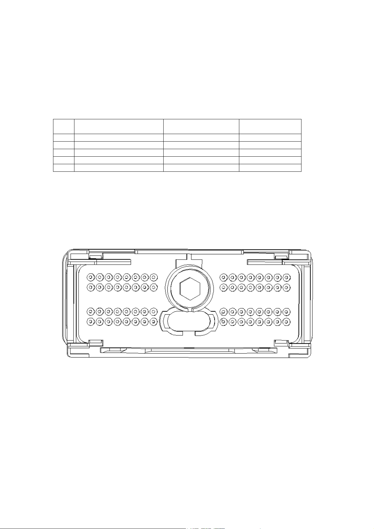
The A4E2 uses an integral rectangular 64-pin Delphi connector to interface to the OEM
machine wiring harness.
The connector comprises the following components
Qty Description Delphi Part Number Perkins Part
Number
1 Plug Assembly 15488667 TBA
1 Wire Dress Cover 15488664 TBA
2 Terminal Lock (TPA_) 15404650 TBA
N/A Contact Socket (Terminal) 15359002 TBA
N/A Sealing Plug 12129557 TBA
The above component will be available in kit form. The kit will provide all the necessary
components to make one basic engine connection.
The wire dress cover must be fitted to prevent direct jet washing onto the rear connector seals
The diagram below illustrates the pin layout, looking from the rear of the connector
25 26 27 28 29 30 31 32
17 18 19 20 21 22 23 24
9 10 11 12 13 14 15 16
1 2 3 4 5 6 7 8
7mm
57 58 59 60 61 62 63 64
49 50 51 52 53 54 55 56
41 42 43 44 45 46 47 48
33 34 35 36 37 38 39 40
Tightening the OEM Connector
A central 7mm AF hex screw retains the connector. This screw should be tightened to a
torque of 5Nm+/- 1 (3.7+/-0.7lbft).
Perkins Engines Company ltd does not recommend the use of “non conductive grease” with
the ECM connector.
ECM connector Wire Gauge Size
All connections must be made with 0.82mm² (18AWG) wire with GXL type insulation.
Min outside diameter (Inc Insulation) = 1.85mm
Max outside diameter (Inc Insulation) = 2.5mm
Page 28 of 92 1104D and 1106D Electronic Application and Installation Guide
Page 29

Perkins Confidential Green Draft 3.2 Aug 2005
ECM Connector Terminals
The OEM connector terminals should be Delphi p/n 15359002
The terminals should be crimped according to the following instructions
Hand Crimping For Prototype machines and Low Volume
Production:
A hand crimp tool and appropriate Die are required for crimping Contact sockets - (Delphi p/n
15359002). The hand crimp tool and removal tool for removing the Sockets from the
connector body are available from Power and Signal Group (PSG)7
Existing Delphi Solution
Component Perkins part
Contact sockets TBA 15359002
HT micro 100W Crimp
Tool with Die – European
Use Only
Delphi Crimp Tool XX 12129557
Removal tool N/A 15314902
New solution
New contacts are being developed which are compatible with the crimp tools used at tier 2.
This is expected to be released in September 2005 and will be the preferred solution.
Component Perkins part
Contact socket TBA N/A
Crimp Tool number 1U5804 Deutsch HDT-48-00
Removal tool N/A 15314902
Note: The insulation should be stripped to 5 mm from the end of the wire. Only a single wire
must be crimped into each terminal.
Supplier Part number
number
N/A HT42000480-1
Supplier Part number
number
Machine Crimping For High Volume Production
The hand tool may not be the appropriate solution for crimping terminals in a high volume
production environment. The OEM’s harness manufacturer should contact PSG directly for
details of high volume crimp solutions:
Terminal Retention
Once all terminals have been crimped and inserted into their correct holes in the connector
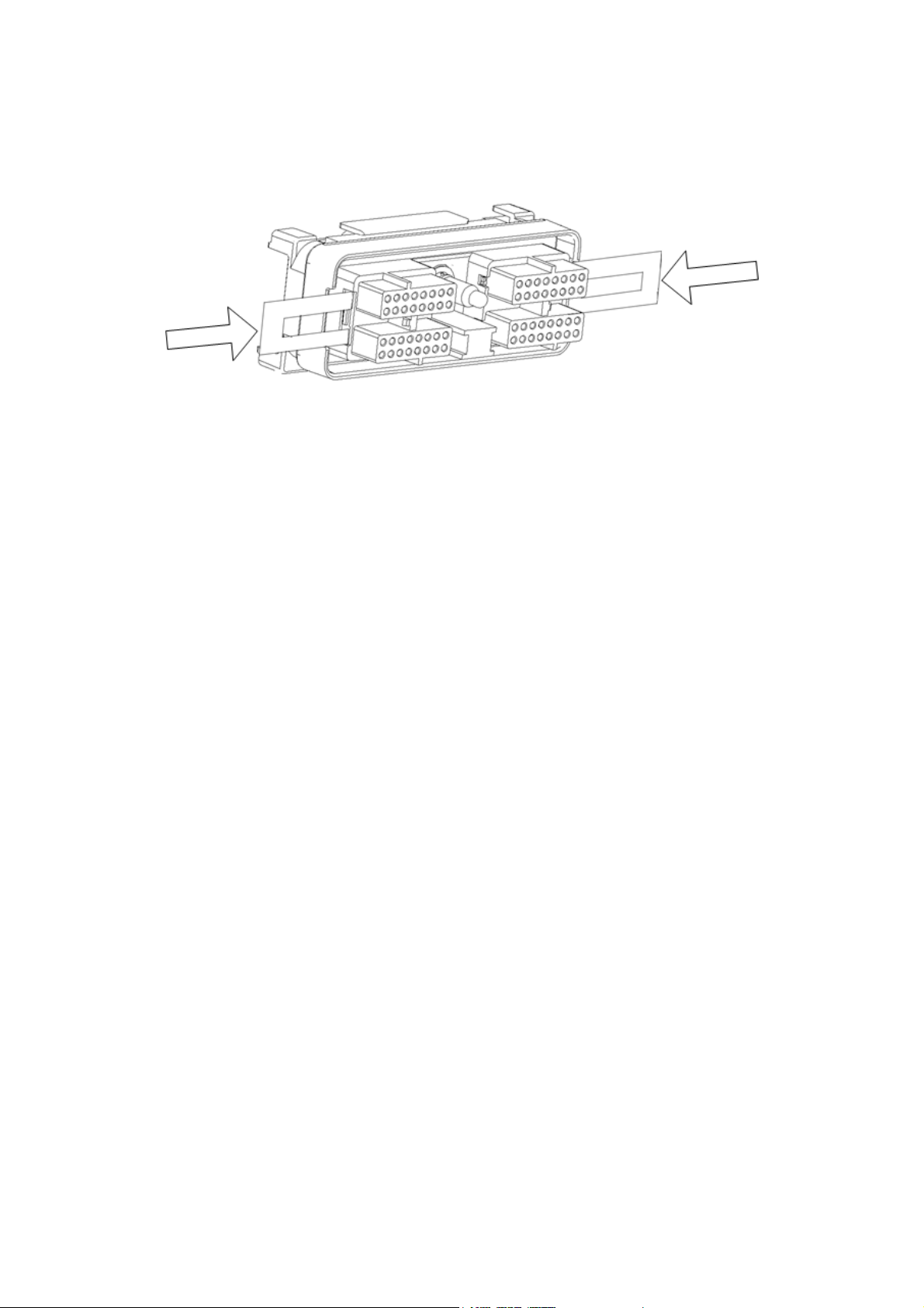
body, then they should be held in place with the two terminal position assurance parts.
Terminal Position Assurance - (Delphi p/n 15404650)
Note: It is critical that two terminal position assurance components are used.
Page 29 of 92 1104D and 1106D Electronic Application and Installation Guide
Page 30
Perkins Confidential Green Draft 3.2 Aug 2005
Connector body and terminal assurance components
When a terminal has been properly crimped and retained correctly, it will be able to withstand
a “pull test” of 45N (10lb)
ECM connector sealing plug installation guidelines
All unused connector socket slots must be filled with sealing plugs - Delphi p/n 12129557.
Due to the small size of the sealing plugs, it may be quicker to install sealing plugs in all
cavities, and then remove those which are not required, rather than to try to fit the sealing
plugs when wires have already been inserted into the back of the connector.
Note: do not use “non conductive” grease to seal unused terminal cavities.
OEM harness Retention at the ECM
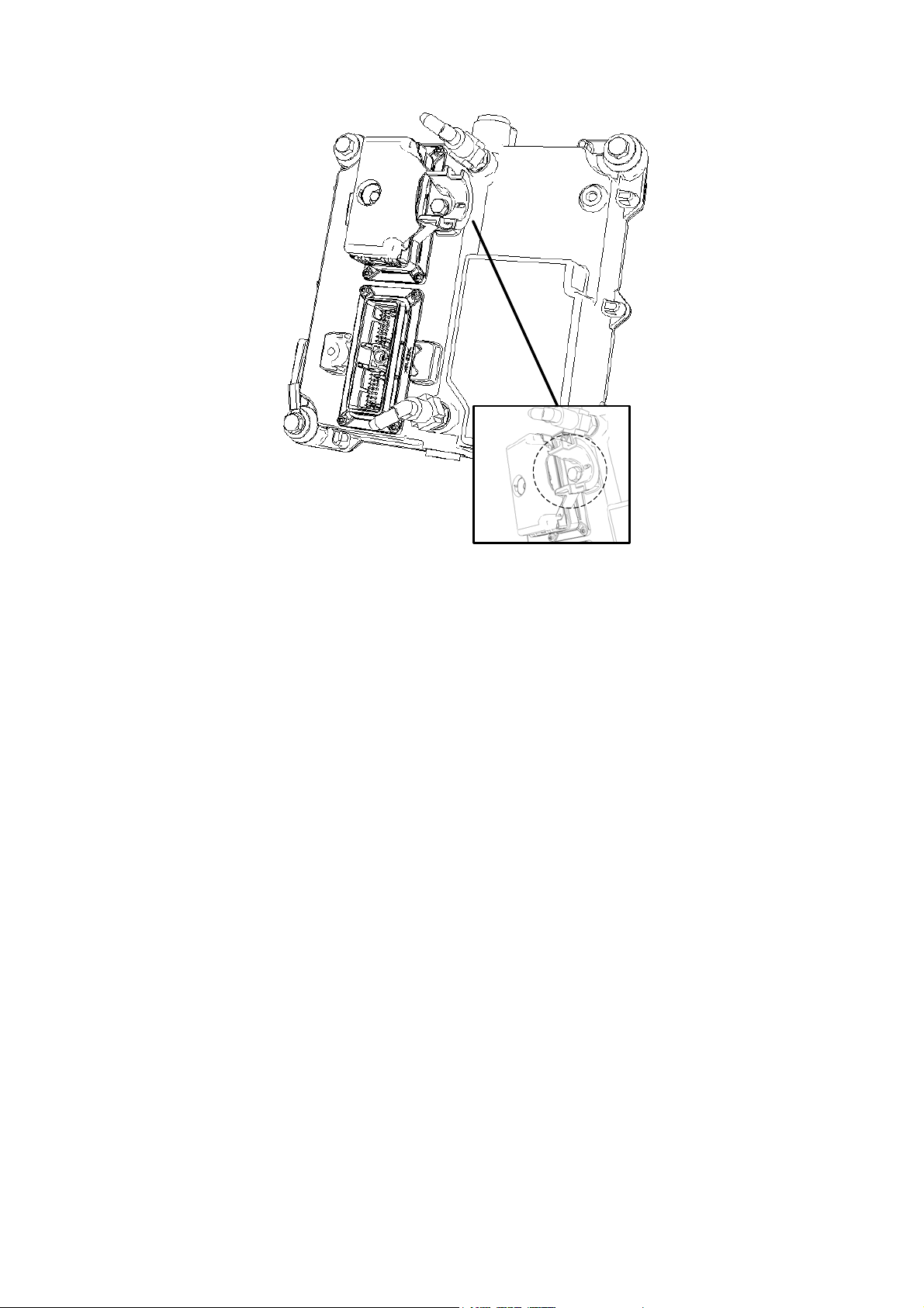
A wire strain relief component should be used to prevent ECM connector damage. The wire
strain relief component is assembled to the ECM using a tap tight screw. See diagram below:
Strain relief Perkins part number 1757P0679
Page 30 of 92 1104D and 1106D Electronic Application and Installation Guide
Page 31
Perkins Confidential Green Draft 3.2 Aug 2005
Harness Wiring Standards
General Recommendations for Machine Wiring harnesses
The following are general “good practice” for wire harnesses. It is the responsibility of the
machine designer to follow standards appropriate to the application type and to the
geographical territory where the machine will be operated. These recommendations do not
replace in any way any industrial standards or legislative requirements:
Connectors
It is strongly recommended that high quality, sealed connectors are used throughout.
Automotive standard components are not necessarily suitable as they are often only designed
for a very low number of disconnect/reconnect cycles.
Connectors should be horizontally mounted rather than vertically mounted to prevent ingress
of water/chemicals. Whenever possible, connectors should be mounted such that they are
protected from direct exposure to extreme cold. Connectors can be damaged by frost if water
does penetrate the seals.
Cables should not bend close to the connector seals, as the seal quality can be
compromised.
The correct wire seal must be selected for the diameter of wire used.
Cables should be selected of an appropriate cross section for the current and voltage drop
requirements
Where large numbers of wires go to the same connector, it is essential that no single wire is
significantly shorter than the others, such that it placed under exceptional strain.
Cable routing.
Cables should be routed such that bend radii are not too tight. A cable should not be either in
compression or tension, nor should it be excessively long or loose, such that sections may
Page 31 of 92 1104D and 1106D Electronic Application and Installation Guide
Page 32

Perkins Confidential Green Draft 3.2 Aug 2005
become caught or trapped. Clips should be used at regular intervals to support cables. These
clips should be of the correct diameter to grip the cable firmly without crushing it.
Ideally, harnesses should not rub against any mechanical components. The only points of
contact should be clamps and connectors. If this is not possible then as a minimum they
should not touch components that are hot, that move or vibrate, or that have sharp edges
Conductors carrying high currents or voltages, particularly when these are alternating or
switched, should be physically separated from conductors carrying small signal currents. In
particular, high current and signal wires should not run parallel in the same harness bundle for
any significant distance. Ideally, if high current wires must be in proximity to signal wires then
they should cross at right angles.
The engine harness should not be used by the installer for as a support for any components
that are not supplied as part of the engine. For example, external hoses and wires should not
be tied to the engine harness.
Mounting location for electronic modules
The least harsh possible location should be selected for an electronic component or module,
even one that is robustly designed. Select the mounting location carefully, therefore,
considering exposure to frost, vibration, heat, mechanical damage, or ingress of water, dust
or chemicals.
Care should be taken during design to ensure that components are accessible for repair and
possible replacement in the field. Poor maintenance access may lead to poor quality repairs
in the field.
Electromagnetic Compliance (EMC)
Special measures should be taken to shield cables if the application is to be used in extreme
electromagnetic environments – e.g. aluminum smelting plants.
If screened cable is used, the screens should be connected to ground at one point only. That
point should be central if possible
Connector Supplier Contact Details
All the components required for OEM connection to the ECM are available from Power and
Signal who are the main distributor for Delphi connectors. The UK and US Power and Signal
offices will assist with Delphi connector procurement
Delphi Connector Supply:
Europe and Asia
Andy Huggett –Key Accounts Manager
Power and Signal Group
Tel: (+44) 1933 226747
Email: [email protected]
North America
Mark Domasky – Strategic Accounts Manager – Midwest
Power and Signal Group
Tel: (+001) 920-589-2112
Fax: (+001) 920-589-2114
Email: [email protected]
Technical Information regarding the connector is available form the Electronic Application
team
Page 32 of 92 1104D and 1106D Electronic Application and Installation Guide
Page 33

Perkins Confidential Green Draft 3.2 Aug 2005
Diagnostic Connector
A 9 pin diagnostic connector is fitted to the engine wire harness on all industrial engines.
Various diagnostic and development tools may use the connector to access the engine data
links.
If the connector is inaccessible when the engine is in the application or no connector is fitted
to the engine wire harness, provisions should be made to allocate an alternative location for
diagnostic connection. In this case it is recommended that a diagnostic connector be wired in
a location that can be easily accessed, free from possible water/dirt ingress and impact
damage. The engine wire harness must not be changed or modified. To wire a diagnostic
connection use the data link pins available on the OEM J1 ECM connector.
It is recommended that all machines with an off engine diagnostic connector wire the J1939
CAN bus and the proprietary CDL/PDL data link.
Mandatory Requirement for Prototype Machines
It is mandatory for all prototype machines to have access to the engines CDL/PDL and J1939
CAN data links.
Termination Resistor
If the engine is the only CAN J1939 devise used on the machine termination resistors will be
required in the circuit to enable error free J1939 communication. It is recommended that the
termination resistors be wired to the OEM machine harness.
9 Pin Diagnostic Connector Part Numbers
Description Deutsch Part Number Perkins Part Number
Receptacle (With Flange) HD10-9-96P TBA
Receptacle HD14-9-96P TBA
Receptacle End Cap HDC-16-9 TBA
Pin Information
Pin Description Diagnostic Connector J1 OEM 64 way Connector
Battery + Pin A
Battery - Pin B
PDL/CDL + Pin D 23
PDL/CDL - Pin E 24
J1939 - Pin F 21
J1939 + Pin G 20
Page 33 of 92 1104D and 1106D Electronic Application and Installation Guide
Page 34

Perkins Confidential Green Draft 3.2 Aug 2005
Stopping the Engine (and Preventing Restart)
There is often some confusion about the different methods and devices used to either stop
the engine or to prevent it from starting. These devices may be divided into the following
categories:
• Ignition Keyswitch
• Emergency Stop Button
• Battery Isolation Switch
• Remote Stop Button
• Datalink stop
Each of these devices is described below to assist the OEM in selecting the method that is
most suitable for his machine and his market. It remains, however, the responsibility of the
OEM to ensure compliance of the machine with legislation in the territories into which it is
sold.
It is recommended that the OEM performs a risk assessment such as a Failure Mode Effects
Analysis (FMEA) on the application to determine the most appropriate method of stopping the
engine and/or preventing it from being restarted.
Ignition Keyswitch
It is a Perkins requirement that all machines have an simple intuitive and accessible method
of stopping the engine. This will normally be a directly wired Ignition Keyswitch. When the
keyswitch is turned to the off position or when the key is removed, power must be removed
from the ignition keyswitch pin (pin 40) of the ECM J1 connector.
Emergency Stop Button
An emergency Stop button is a failsafe method for an operator to stop a machine to protect
people or equipment.
Emergency Stop buttons are defined by national or international standards in terms colour,
functionality, shape, size, latching /locking. In the EU for example, they are described in the
Machinery Directive.
For mobile machines, however, true emergency stop buttons are not always appropriate and
are rarely fitted, due to the following issues:
• The legislation is designed principally for static industrial machinery (e.g. lathe) where
the main power source is mains electricity.
• Stopping a diesel engine in a mobile machine may not always be safe. In particular
the vehicle may need the power to move to a safe position (for example off the public
highway, or off a railway track)
• In practice it is difficult to find components such as safety relays which are suitable for
mounting on mobile machines due to the high vibration and water ingress protection,
and the low voltages that occur during starting
• Fail-safe wiring can be a cause of machine unreliability and can create faults which
are difficult to detect in the field.
If a true emergency stop button is required for an application it is recommended that it is
implemented such that both the +battery and the ignition keyswitch lines are cut directly by
the emergency stop button.
Perkins do not provide a standard recommendation, or approval, for a circuit for multiple
emergency stop buttons, as the differences between application mean that significant time
and resources are necessary to design a system which will be fail safe without adversely
affecting reliability.
Page 34 of 92 1104D and 1106D Electronic Application and Installation Guide
Page 35

Perkins Confidential Green Draft 3.2 Aug 2005
Battery Isolation Switches
Battery Isolation switches are usually fitted in the battery or the engine compartment of a
machine. On some machines there may be a small number of low current devices which are
not switched off by this device e.g. clocks or anti-theft tracking devices.
The function of a battery isolation switch is as follows:
• Prevent battery discharge during vehicle shipping or storage
• Protect service technicians from danger caused by inadvertent engine crank or start
.To offer good protection of service personnel is it possible to provide a switch which
can be locked in the open position (e.g. with a padlock) and the key removed and
given to the service engineer who is working on the dangerous components
The battery isolation switch is not a suitable method for stopping an engine as it is not
guaranteed to stop the engine as the ECM may continue to operate with power generated by
the alternator.
It is also possible that opening the battery isolation switch when the engine is running will
cause an “alternator load dump”. This is a kind of electrical transient which can cause
damage to electronic components
Battery isolation switches are normally fitted in the negative path, close to the battery.
Remote Stop Button
Remote stop is intended to provide a convenient method of stopping the engine. It is not
designed to be fail safe and so should not be used assure the protection of either personnel
or equipment
Remote stop buttons may be used on large machines, which can be operated from ground
level and where the operator wants to stop the machine without climbing into the cab.
There are a number of variations on remote stop button circuits. The 1106D uses single
normally open contacts, which must be closed to stop the engine.
The remote stop button will function as follows:
A single switch to ground input on pin 48 of the ECM J1 Connector (Several stop buttons can
therefore be connected in parallel)
When the switched is closed (or if a button is stopped for longer than 150mS), then the
engine will stop.
The ECM will remain ON, so it will continue to communicate over J1939 and with the service
tool. Note however that it will continue to draw power from the battery so if it is left in this state
it will eventually result in a flat battery.
The engine may be restarted by opening the switch and activating the starter motor.
The red “mushroom” emergency stop buttons must not be used for remote stop functions as
they may be mistaken for emergency stop buttons as described above.
Datalink stops
It will be possible to stop the engine via a datalink (J1939 or CDL). As per the remote stop
button, described above, the datalink stop is not fail safe and does not meet the requirements
of emergency stop legislation so should not be relied on to assure the safety of machine
operators or other personnel.
Datalink stops may be used in the following circumstances
• Immobilisers
• Machine protection strategies
• Automatic machine features (e.g. idle shutdown timer)
Page 35 of 92 1104D and 1106D Electronic Application and Installation Guide
Page 36

Perkins Confidential Green Draft 3.2 Aug 2005
• Stopping machines by radio control or other telemetry. Geo-fencing is a particular
application, where a machine will not operate outside defined map coordinates
It is recommended that if such features are implemented, then they are clearly documented
and communicated to the final users and owners of the machine. If this is not done then there
may be complaints that the engine is stopping unexpectedly.
Common problems with the application of stop devices
• It is possible, although extremely rare, that diesel engines continue to run even if all
electrical power is removed. This can happen when high quantities of oil vapour or
other inflammable gases are present in the air into the engine. The only way to
prevent this is to provide an air inlet shut-off valve (slicer valve). It is not common
practice to fit such devices to all engines, but they should be considered where there
is a risk of flammable gases (e.g. in petroleum applications), or where the application
demands high engine gradebility (slopes)
• Some hazards are present when the engine is being cranked by the starter motor, as
well as when it is running. For example, components will still rotate, hydraulic
pressure will still be present, fuel may still be pump to high pressures.
• If an emergency stop button is pressed, to cut power to ECM and ignition, but is
released while the engine is still turning, it is possible for the engine to continue to
run.
Page 36 of 92 1104D and 1106D Electronic Application and Installation Guide
Page 37

Perkins Confidential Green Draft 3.2 Aug 2005
Engine Speed Demand
There are 5 different methods of controlling the speed of the engine.
• Analog Sensor
• Pulse Width Modulation (PWM) Sensor
• PTO mode - also known as “engine speed cruise control” or “set speed control”.
• Multi Position Throttle Switches
• Torque Speed Control - TSC1 (Speed control over CAN J1939)
The speed demand options must be selected at the time of engine order so that the ECM will
be configured correctly. For the type or pedal, lever or control device selected.
Analog Sensor
Device Description
Two inputs are available for Analog throttle devices, which may be either a pedal, lever or
cable operated. The Analog sensor gives a DC Analog output in the range 0.5 to 4.5 volts,
when connected to the engine ECM. A regulated 5V 200mA power supply is provided by the
ECM.
The Analog sensor should use non-contact Hall effect technology. Robust potentiometer
contact sensors designed for use in vehicles may be considered under no circumstances
should ordinary carbon track or wire wound potentiometers be used, as they will not
be reliable.
For all mobile applications, and those where a rapid change in engine speed could cause a
hazard, an idle validation switch is required. The idle validation switch closes to ground when
the sensor is in the minimum position.
Off idle switches and kickdown switches are not monitored by the engine ECM.
This Analog input must only be used to control engine speed from a direct operator input, and
is not suitable as the mechanism for speed control by another electronic controller.
There is no special requirement for a relationship between angular movement of the pedal
and output voltage.
This document does not measure component acceptability in terms of:
• Temperature
• Vibration
• Electromagnetic Compatibility
• Design life
• Supply voltage requirements (min, max, stability)
• Legal Compliance
It the responsibility of the OEM and the throttle device manufacturer to ensure that the
component is suitable for the application in which it is to be used.
Evaluating Component Compatibility
The following procedure should be used to evaluate whether an Analog throttle is compatible
with the engine ECM. This may be used either by the OEM in selecting components or by the
manufacturer of devices which are to be connected to the engine.
The following test circuits must be used when evaluating Analog throttle devices.
Page 37 of 92 1104D and 1106D Electronic Application and Installation Guide
Page 38
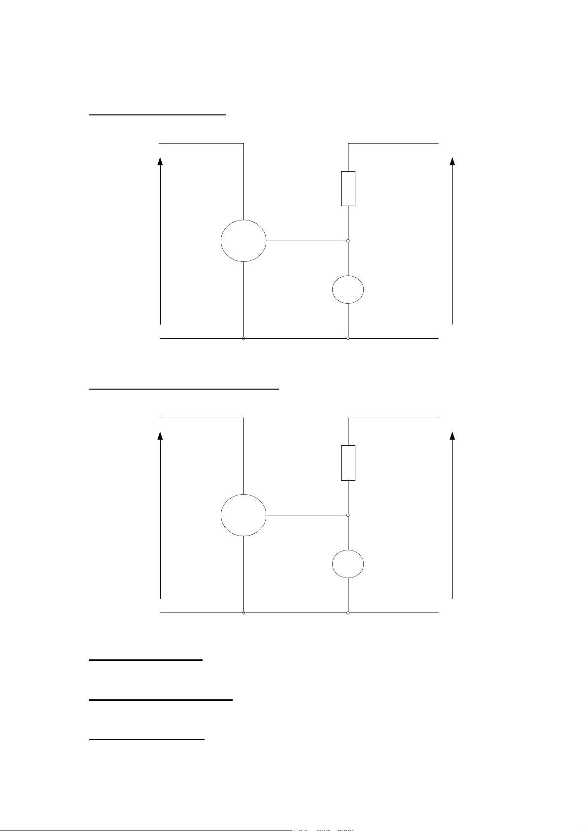
Perkins Confidential Green Draft 3.2 Aug 2005
Analog Input Test circuit
22K
V+
normal
supply
voltage of
device under
test
Device
Under
Test
V-
Sig
13V DC
V1
Idle Validation Switch Test Circuit
IVS
Device
Under
Test
ground
V+
IVS
IVS
Normal
supply
voltage of
device
(Hall Effect
Devices only)
2K
13V DC
V2
Test Procedure
Test 1: Output at Min position
Place the Device Under Test (DUT) in it’s minimum or “released” condition.
Measure the voltage V1
Test 2: Output at Min position: forced
Without causing damage, pull the pedal/ handle hard against the minimum travel end stop.
Measure the voltage V1
Test 3: Output at Max position
Place the DUT in it’s maximum or “fully depressed” condition.
Page 38 of 92 1104D and 1106D Electronic Application and Installation Guide
Page 39

Perkins Confidential Green Draft 3.2 Aug 2005
Measure the voltage V1
Test 4: Output at Max position: forced
Without causing damage push the pedal/ handle hard against the maximum travel end stop.
Measure the voltage V1
Test 5: IVS switch Closed Voltage
Place the DUT in it’s minimum or “released” condition.
Measure the voltage V2
Test 6: IVS switch Opening Threshold
Place the DUT in it’s minimum or “released” condition.
Test 7: IVS switch Open Voltage
Place the DUT in it’s maximum or “fully depressed” condition.
Measure the voltage V2
Test 8: IVS switch Closing Threshold
Place the DUT in it’s minimum or “released” condition.
Test 9: track resistance (potentiometer type sensors only)
If the DUT is a potentiometer type device, disconnect it from the test circuit and measure the
resistance across the track (from V+ to V-)
Required Values
If the results obtained from the tests above are in the ranges specified below, then the device
will be compatible with the default values in the ECM.
Test Parameter Units Min Nominal Max
1 Output at Min position Volts 0.45 0.6 0.7
2 Output at Min position: forced Volts 0.4 0.6 3 Output at Max position Volts 3.8 4 4 Output at Max position: forced Volts - 4 4.5
5 IVS switch Closed Voltage Volts 0 0.5 1.2
6 IVS switch Opening Threshold Volts 1.08 1.15 1.22
7 IVS switch Open Voltage Volts 4 10 24
8 IVS switch Closing Threshold Volts 1.08 1.15 1.22
9 Potentiometer Track resistance K Ohms 1 2.5 3
If the results of the tests are not in the range specified in the table above, then the device will
not be compatible with the default settings in the ECM. Contact the electronic applications
team to determine whether it will be possible to configure the input to meet the device.
Analog Sensors –Connection details
Analog input 1
Sensor terminal ECM J1
Connector Pin
Assignment
Sensor + 41
Sensor signal 54
Sensor – 33
Idle validation Switch 45
Switch return 35
Page 39 of 92 1104D and 1106D Electronic Application and Installation Guide
Page 40

Perkins Confidential Green Draft 3.2 Aug 2005
Analog input 2
Sensor terminal ECM J1
Sensor + 42
Sensor signal 55
Sensor – 34
Idle validation Switch
(closed at idle)
Switch return 35
Connector Pin
Assignment
44
PWM Sensor - Compatibility
Device Description
One input is available for a PWM throttle devices which may be either a pedal, lever or cable
operated. A regulated 8V, 100mA power supply is provided by the ECM.
Component Compatibility
The sensor should have a sinking output driver with a frequency of 500hz (+/- 50hz). The
sensor should give a valid output within 150ms of power being applied.
When mounted on the pedal and lever the duty cycle should be as follows
Position Acceptable signal duty
cycle range
Released (low idle) 10 to 22%
Fully Depressed 75 to 90%
Connection details
PWM sensor 1
Sensor terminal ECM J1 Connector
Pin Assignment
Sensor + 43
Sensor signal 53
Sensor – 33
PTO mode
PTO mode has also previously been referred to as “engine speed cruise control” or “set
speed control”
PTO mode cost effective way to control engine speed as for the minimum implementation it
only requires buttons to raise and lower engine speed.
Another benefit is that it can be used in an application where it is necessary to control the
engine speed from several different points on the machine. Likewise, it is a simple method
controlling engine speed by another controller
Page 40 of 92 1104D and 1106D Electronic Application and Installation Guide
Page 41

Perkins Confidential Green Draft 3.2 Aug 2005
The disadvantage of controlling speed via PTO mode is that it takes some time to ramp up or
down to the required speed.
ON/OFF switch
When this switch input is open then the PTO mode cannot be engaged, and none of the other
buttons will have any effect. When the switch is turned off, the memorized speed will be
Set/lower Button
When the PTO mode is on but not engaged, the first time that the set button is pressed it will
save the current engine speed as the memorized speed, and the engine will try to run at this
speed.
Once that a PTO speed has been engaged, if the pressed again, or if it is held down, then the
engine speed will be lowered.
Raise/ Resume Button
If the resume button, is pressed before the set button, immediately after start or after
switching ON the cruise control ON/OFF switch then the engine will go to the preset speed as
described below.
If a the PTO mode has already been engaged by the set button, then the resume raise button
can be pressed or held down to increase the speed.
After the PTO mode has been disengaged using the disengage switch described below, then
pressing the Resume/Raise button will set the engine speed to the last memorized speed.
Disengage Switch
The disengage switch input is opened the engine speed will not follow the memorised speed,
but will return to the next highest engine speed demand
The disengage switch may be a operator panel switch, or may be a micro switch on the
brake, clutch, or other component of the application
Preset Speed
The preset speed is programmed via the service tool. A speed may be selected such that if
the resume button is pressed, before the set button has been pressed, then the engine speed
will jump straight to this speed.
Note: this feature will not be fully supported in the ECM or in the service tool by July 2005
PTO mode lamp
An optional lamp may be fitted. The positive terminal of the lamp is connected to the battery
positive after the ignition keyswitch. The negative terminal of the lamp should be connected to
pin 61 of the ECM J1 Connector
The lamp will FLASH when PTO mode is switched ON but is NOT ENGAGED. When the
PTO mode is engaged then the lamp will be on SOLID when the PTO mode is ON and
ENGAGED.
Page 41 of 92 1104D and 1106D Electronic Application and Installation Guide
Page 42

Perkins Confidential Green Draft 3.2 Aug 2005
Example of PTO mode operation
It is recognized that the precise function of the PTO mode is difficult to understand from a written text document, especially for engineers who do not have
English as their first language. The following table illustrates the operation of the PTO mode feature. In this example, the preset speed has been set on the
service tool to 1800 rpm.
On/Off Switch 0 1 1 1 1 1 1 1 1 1 1 1 1 1 1 0 0 0 1
Interrupt Switch 1 1 1 1 1 1 1 1 1
Quickly
open 1
Quickly
open 1 1 1 1 1 1 1
Quick
Set/Lower Switch 0 0 0 0 0 0 0 0
Raise resume 0 0
Throttle Pedal demand 1200 1200 1200 1200 1900 1200 1200 1200 1200 1200 1200 1200 1200 1200 1200 1200 1200 1200 1200
Memorised Speed 1800 1800 1800 1800 1800 1800 1820 2050 2030 2030 2030 2030 1200 1180 2430 1800 1800 1800 1800
Resulting engine speed 1200 1200 1800 1800 1900 1800 1820 2050 2030 1200 2030 1200 1200 1200 2430 1200 1200 1200 1200
Comments
Quick
Close 0 0 0
PTO mode not enabled
PTO mode disenaged
PTO jumps to memorised speed Pedal overrides PTO (max wins)
Quick
Close
Close
Hold
Close
3 secs 0 0
Speed raised by 20 RPM
Speed ramps up
Lowered by 20 RPM
0 0 0
Quick
Close 0 0 0
Disengage - speed retuns to next highest
demand (Throttle pedal)
Resumes to 2030
Quick
Close
Disengage - speed retuns to next highest
demand ( Throttle pedal)
Quick
Close
Sets memorised speed to current speed
0 0 0 0
Hold
Close
3 secs 0
Memorized speed lowered by 20RPM but
now pedal is highest wins
Speed ramps up
Quick
Close 0
PTO mode switched off. Preset memorised
speed now
no effect as PTO mode is not enabled
Quick
Close
Quick
Close
PTO mode disengaged
no effect if both buttons are pressed at once
Page 42 of 92 1104D and 1106D Electronic Application and Installation Guide
Page 43

Perkins Engines Company ltd Confidential Green Draft 02 Nov 2004
PTO mode Connection table
Function ECM J1 Connector
Set / Lower button 51
Raise / Resume
button
ON/OFF switch 49
Disengage switch
(normally closed)
PTO mode lamp 61
Pin Assignment
50
52
Multi Position Throttle Switch (MPTS)
Four switch inputs are available on the ECM for switched throttles. The ECM may be
configured so that different combinations of switch inputs will relate to different engine speed
demands. There are 16 different combinations of states of these 4 switches, although not all
of these combinations need to be programmed.
If a switch combination is detected which has been configured as “Not Valid” then a fault code
will be raised and the ECM will ignore the MPTS for the rest of the key cycle.
This is a very powerful and flexible feature that may be used in a number of ways. For
example:
• Principal speed control method in a hydrostatic machines where engine speed is
selected and then not required to be frequently changed by the operator. It is in this
respect a good alternative to a hand throttle as the speeds selected on the switch.
can be designed to correspond to the optimum operating speeds of hydraulic pumps.
A rotary encoded 10 position switch component is available for this function. Please
contact the electronic applications team for further details.
• Machine limp home speed feature. For example, if the normal throttle fails the
operator could remove a fuse or a link and the engine would go to a speed that
would allow the machine to be moved. In this application only one of the available 4
switch inputs would be used.
• Elevated idle. For example the OEM could increase the idle speed when work lights
are switched on so that the alternator will provide sufficient current to recharge the
battery. In this application only one of the available 4 switch inputs would be used.
The following table illustrates how the ECM may be configured for a 10 position rotary switch.
Page 43 of 92 1104D and 1106D Electronic Application and Installation Guide
Page 44

Perkins Engines Company ltd Confidential Green Draft 02 Nov 2004
52
Engine
position
Speed
Multi-Position Switch Configuration Example
Switch 4 Switch 3 Switch 2 Switch 1 Switch
Open Open Open Open Not valid 800
Open Open Open Closed 1 800
Open Open Closed Open 3 1800
Open Open Closed Closed 2 1400
Open Closed Open Open 7 2050
Open Closed Open Closed 6 2000
Open Closed Closed Open 4 1900
Open Closed Closed Closed 5 1950
Closed Open Open Open Not valid 800
Closed Open Open Closed Not valid 800
Closed Open Closed Open Not valid 800
Closed Open Closed Closed Not valid 800
Closed Closed Open Open 8 2100
Closed Closed Open Closed 9 2200
Closed Closed Closed Open Not valid 800
Closed Closed Closed Closed 10 2350
Multi-Position Throttle Switch connections
Function ECM J1 Connector
Pin Assignment
MPTS Switch 1
MPTS Switch 2 51
MPTS Switch 3 50
MPTS Switch 4 49
Switch return 35
Torque Speed Control TSC1 (Speed Control Over CAN)
A special J1939 message called Torque/Speed Control #1 (TSC1) allows other electronic
devices to control or to limit the engine speed. This message is explained in detail in the
J1939 section of this application and installation guide
Arbitration of speed demand
In applications where there is more than one source of engine speed demand, it is necessary
to arbitrate between the different demands. There are 3 methods of arbitration:
• Max Wins. The highest speed demand is the one that controls the engine. This is the
default configuration
• Manual Selection switch. A switch input can be used to define which speed input has
control. This is particularly useful in applications where there are 2 driver seat
positions.
• Tsc1 override. As described above, the Tsc1 message over J1939 will override speed
demand from any other source.
Manual Throttle Selection Switch
A switch input is available on pin 47of the ECM J1 connector, which can be configured to
manually select the active speed demand channel. If the switch input is open then Speed
demand 1 is selected. If the switch is closed then speed demand 2 is selected.
Page 44 of 92 1104D and 1106D Electronic Application and Installation Guide
Page 45

Perkins Engines Company ltd Confidential Green Draft 02 Nov 2004
Cold Starting Aid.
Control of Glow Plugs by the Engine ECM
Glow plugs are fitted as standard on the 1104D and 1106D.
When the ignition keyswitch is switched ON, the engine ECM will monitor the coolant
temperature and the inlet air temperature and decide whether the glow plugs are required. If
so then the ECM will drive ECM connector pin 57 to ground, activating the glow plug relay.
The Glow plug relay is supplied and fitted by the OEM.
Relay, Fuse and Cable Gauge Specification
The relay coil should not draw more than 1A.and should be fitted with either a resistor or
diode to suppress flyback energy (back emf) when the relay is de-energised.
As the glow plugs may be activated during cranking, when the battery voltage may be low, it
is recommended that relay is specified such that it will close at a voltage of 60% of nominal
battery voltage or lower.
The relay contacts should be rated to withstand the current characteristics outlined in the
table below. Note that for the purpose of relay specification, the glow plugs are a purely
resistive load (no inductive element).
Although the glow plugs are normally operated only for a short time, in cold ambient
conditions, best practice would be to size the cable to withstand the stabilized glowplug
current permenantly. This will allow for a relay which fails closed. For example a 4 Cylinder
12V application should have wire sized to carry 50A. Refer to the recommended cable sizes
in the table below.
Engine: 1104D 1106D
Supply Voltage: 12V 24V 12V 24V
Current - Initial
Current after 4 seconds
Current after 8 seconds
Recommended Fuse
To SAEJ1888 ( slow blow)
Recommended min cable
gauge - mm
GLX cable)
2
(SAE J1128
82A 36A 122A 54A
64A 29A 97A 43A
50A 24A 74A 36A
50 30 80 40
2
5mm
2mm2 8mm2 3mm2
Wait-to-Start / Start Aid active lamps
On a cold start, when the ECM decides that it is necessary for the glowplugs to be activated
prior to starting, a lamp output will indicate to the operator that he needs to “wait to start”.
Note that it is possible that start aids will also be used either during cranking or when the
engine has started. The wait to start lamp will not be active in these conditions. For further
information refer to the Lamp Output section.
Note that the ECM will also transmit a parameter on the J1939 datalink indicating the status of
the Wait to Start lamp (see section on J1939 support).
Page 45 of 92 1104D and 1106D Electronic Application and Installation Guide
Page 46
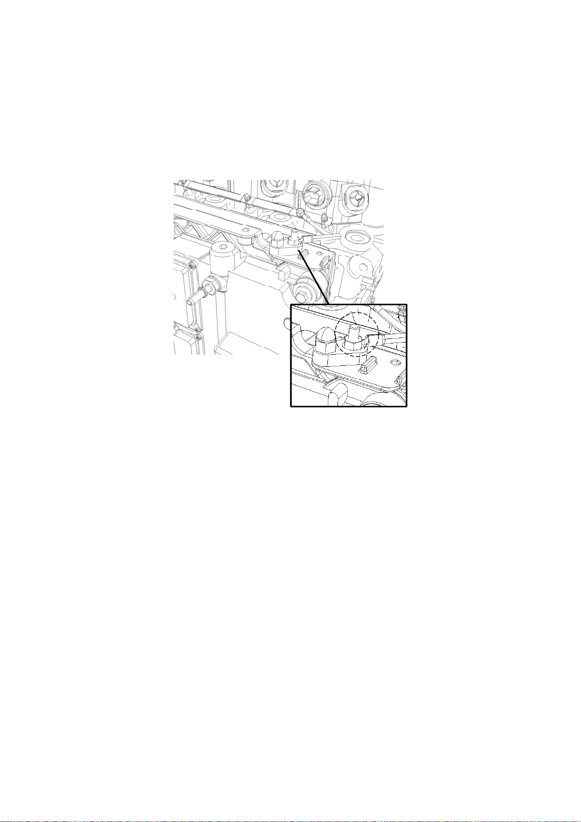
Perkins Engines Company ltd Confidential Green Draft 02 Nov 2004
OEM / Operator control or override of the Glow Plugs
The ECM glow plug control strategy has been developed in a cold chamber to be suitable for
the majority of applications.
There may be some applications that require a specially adapted strategy for control of the
start aid. In such cases it will be necessary for the OEM or operator to control the start aid.
Examples of applications that may require special starting strategies are:
• Engines in extremely cold climates that are fitted with block heaters.
• Engines that drive high loads during run up e.g. compressors.
Busbar connection point
An insulated M6 terminal post is provided for the machine harness connection to the busbar,
this is located to the top right hand side of the ECM bracket. A 5.5-6 mm diameter ring
terminal is required to connect the machine harness; this should be capable of handling an
80Amp current.
The existing terminal nut is used to locate both the engine-side and harness-side ring
terminals to the post. A 10mm ring spanner is required to tighten the terminal nut to a torque
of 6 Nm ± 2Nm.
Customers who paint their engine are required to shield the terminal post prior to painting.
Ether Cold Start Systems
Ether Cold start systems are not currently approved for use with 1106D and 1104D engines.
Page 46 of 92 1104D and 1106D Electronic Application and Installation Guide
Page 47

Perkins Engines Company ltd Confidential Green Draft 02 Nov 2004
Operator Displays
Gauge Drivers
OEM’s are increasingly selecting datalink driven intelligent displays for their applications,
instead of traditional gauges and lamps directly driven from sensors or engine ECM.
If a needle type Analog gauge is required, to display an engine parameter such as engine
speed, oil pressure or coolant temperature, then it is recommended that the OEM uses a
gauge or display that can use the parameters broadcast by the ECM on the J1939 datalink.
As an alternative, traditional single wire gauge “senders” may be used if a suitable tapping is
available. If this implementation is required, then please contact the electronic applications
team to discuss requirements.
A traditional tacho signal may be obtained from the “W” terminal of the alternator, although
this will not be as accurate as the value sent on the J1939 datalink.
Warning: The engine wiring harness must NEVER be modified to use the signal from
the sensors connected to the engine ECM. This action would invalidate the engine
warranty.
Lamp Outputs
The lamp strategy is designed to display the maximum amount of information on the minimum
number of lamps.
There are five lamp outputs available:
1. Red Stop Lamp
2. Amber Warning Lamp
3. Wait to Start Lamp (cold start lamp)
4. Oil Pressure lamp
5. PTO mode lamp
It is mandatory for the OEM to fit the Red Stop Lamp (1) and Amber Warning Lamp (2) unless
a datalink driven intelligent display is fitted, which fulfils the specification outlined in the next
section.
Lamps three, four and five are optional.
Page 47 of 92 1104D and 1106D Electronic Application and Installation Guide
Page 48
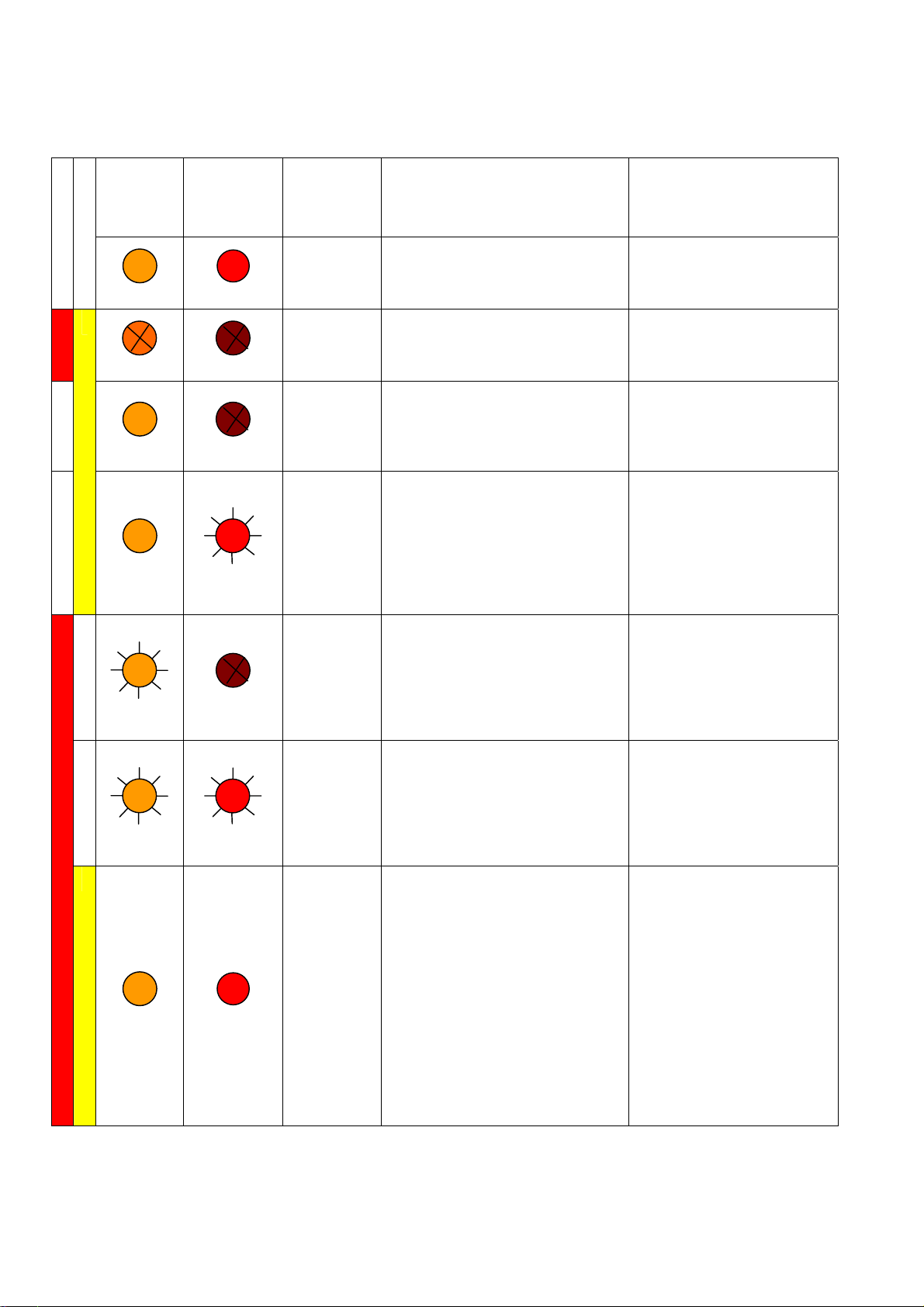
d
Warning
Lamp
(Also known
as Alert
.
Lamp)
Relate
Engine Management System
Perkins Engines Company ltd Confidential Green Draft 02 Nov 2004
Indicator lamps Logic
On
Off
On
On
Flash
Flash
On
Shutdown
Lamp
(Also known
as Action
Lamp)
On
Off
Off
Flash
Off
Flash
On
Lamp
State
Description of what Lamp
Status is Indicating
Bulb Check When the ignition is turned on
the EMS shall illuminate each
bulb for 2 seconds and
extinguish them afterwards.
No Faults
Present.
With both lamps off whilst engine
is running then there are no
currently active warnings
diagnostic’s or events.
Active
Diagnostic
Should the warning lamp
illuminate during engine running
this indicates that an Active
diagnostic (Electrical fault) is
present.
Derate.
(Invoked by
Active
Diagnostic)
Should the warning lamp
illuminate and the shutdown
lamp flash during engine running
this indicates that an Active
diagnostic (Electrical fault) is
present. The diagnostic is
sufficiently serious to invoke
engine derate.
Warning
(Warning
only)
Should the warning lamp flash
during engine running this
indicates that one or more of the
engine protection strategy
warning values have been
exceeded but not to a level that
will invoke Derate or Shutdown.
Derate.
(Warning
and
Derate).
Should both the Warning lamp
and Shutdown lamp flash during
engine running this indicates that
one, or more, of the engine
protection strategy values have
been exceeded beyond the level
required to invoke engine Derate.
Engine
Shutdown
Should both the Warning lamp
and Shutdown lamp illuminate
during engine running this
indicates that either
1. One or more of the
engine protection
strategy shutdown
values has been
exceeded.
2. A serious Active
diagnostic has been
detected.
Engine State
Key on but engine has yet
to be cranked.
Engine is running with no
detected faults.
Engine is running normally
but has one or more faults
with the engine
management system.
Engine is running but has
one or more Active
diagnostic events that have
initiated engine derate.
Engine is running normally
but has one or more
monitored engine
parameters outside of the
acceptable range.
Engine is running but one
or more of the monitored
engine parameters has
gone beyond that of
warning only and has now
exceeded those set for
engine derate.
Engine is either shutdown
or shutdown is imminent,
one or more monitored
engine parameters have
gone beyond that of
warning or derate and have
now exceeded those set for
engine shutdown. Or a
serious Active diagnostic
has been detected
Shortly after (time duration to be
agreed) engine will shutdown.
Page 48 of 92 1104D and 1106D Electronic Application and Installation Guide
Page 49

Perkins Engines Company ltd Confidential Green Draft 02 Nov 2004
Datalink Driven Intelligent Displays
Displays may be connected to the engine ECM using J1939 datalink.
Some products that use the CDL may also be compatible. Please contact your local
Applications team to confirm before selecting a CDL display.
Devices that are connected to the J1939 datalink should meet the following standard if the
OEM does not intend fitting the indicator lamps, described above.
Minimum Functional Specification for J1939 display.
• The display always on when the engine is running
• The display should be line-of-sight of machine operator during machine operation
• Display of the whole J1939 fault code including Suspect Parameter Number, Failure
Mode Indicator, and Occurrence number.
• Clear indication of what action, if any the operator is required to take.
• Display of engine speed
• Audible or bright lamp warning when new fault code is detected
• The scaling of any gauges (e.g. coolant temperature) should be such that the needle
is not far to the right of vertical when the engine is in normal operation (this would
give the impression that the engine was abnormally hot, when in fact it is running
within it’s design limits).
Perkins will under no circumstances change the engine J1939 implementation in order to
resolve compatibility issues with gauges or displays other than those supplied directly by
Perkins.
Gauge manufacturers may contact the Electronic Applications team, however for information
and assistance in ensuring that their products are compatible with the engine ECM.
To support new standards and requirements Perkins may add to the fault code table.
Therefore any active engine fault codes including those not recognized or referenced should
be displayed. Perkins recommends that any suspect parameter number and the associated
failure mode identifier are displayed.
Customer Triggered Engine Fault codes
The engine will raise fault codes (event codes) when it’s design limits are exceeded. For
example, for excessive coolant temperature. The fault code algorithms are carefully designed
and validated so that they do not cause spurious codes when there is in fact no fault.
Some intelligent instrument clusters available on the market are also capable of raising fault
codes themselves, based on the information that the engine transmits on J1939 such as
“engine coolant temperature”. The machine designer could set a limit that was more
conservative (lower) than the warning threshold defined by Perkins. This raises the possibility
that the display will say that the engine has a fault, when the engine is in fact running within
its design limits. This is undesirable as it may result in a service technician being called to
resolve a “problem” when in fact no problem exists. It will also cause damage to the
reputation of Perkins and of the OEM.
Perkins recommend therefore, that intelligent display DO NOT have their own fault detection
for engine over temperature / oil pressure etc, but that they use the fault codes generated by
the engine, sent in the J1939 “Diagnostic Message#1 (DM1)”.
Page 49 of 92 1104D and 1106D Electronic Application and Installation Guide
Page 50

Perkins Engines Company ltd Confidential Green Draft 02 Nov 2004
Engine Software Features
Engine Monitoring System
Software will monitor the engine during operation and in extreme conditions make decisions
to protect the engine from damage. The values of four main operating parameters are
monitored Engine Coolant Temperature, Engine Oil Pressure, Intake Manifold Air
Temperature and Engine Speed. The monitoring system will compare parameters
predetermined as dangerous to the engine and depending on the parameter values take
appropriate action. There are three levels of action Warning, De-rate and Shutdown.
General
All parameters work independently using individual threshold values and guard timers.
Consequently, it is possible for more than one parameter to register a warning or de-rate
condition at any one time.
Warning
Each monitored parameter has its own warning trigger threshold. A warning will be triggered
when any parameter equals or exceeds its warning. In addition, for oil pressure, the trigger
threshold varies with engine speed. The ECM will log these events and turn on the
appropriate lamp driver.
De-rate
Each monitored parameter that uses the de-rate function has its own de-rate trigger
threshold. If the de-rate threshold is equaled or exceeded by any parameter for a de-rate
protection will be set active. The engine will de-rate. The ECM will log these events and turn
on the appropriate lamp driver. Whilst de-rate protection is set active, the de-rate percentage
may vary with parameter value
Shutdown
The engine shutdown indication lamp driver will be triggered when any parameter equals or
exceeds it shutdown threshold for a time exceeding its shutdown indication guard time.
Physical engine shutdown will occur only if enabled by the configurable parameter. The ECM
will log these events and turn on the appropriate lamp driver.
Note: All values quoted in tables below are subject to change. Also, the percentage derate
can be confusing. 100% derate does not mean that the engine has no power at all, it means
that the engine will be running on a derate rating. The percentage of normal power that is
available on the derate curve will depend on the rating used, but will normally be
approximately 50% of nominal power
Coolant Temperature
Parameter Temp De-rate %
Warning 113 N/A
De-rate 114 25
115
116
117
118
119 100
Shutdown 118 N/A
Page 50 of 92 1104D and 1106D Electronic Application and Installation Guide
Page 51

Perkins Engines Company ltd Confidential Green Draft 02 Nov 2004
Engine Oil Pressure
Parameter Engine
Speed (rpm)
Warning 700 100
900 150
1000 175
1200 200
Shutdown 700 100
1200 100
1800 100
2400 100
* Derate thresholds will be released Jan 2005 for oil pressure.
Trigger
Pressure
(kPa)
Intake Manifold Temperature
Parameter Temp De-rate %
Warning 82 N/A
De-rate 86 10
87 20
88 30
89 40
90 50
Monitored Inputs for Customer Fitted Sensors
Configurable options will be available that enable the use of discrete ECM inputs to function
as operator warnings and engine protection. The three options to be offered include:
Air Intake
Restriction
Engine Coolant
Level Low
Water in Fuel
Configurable States
The ECM may be configured to take the following action when the monitored element has
reached or exceeded the predetermined limit (switched).
Input State De
bounce
Time
(secs)
SWG Normally
Open
SWG Normally
Closed
SWG Normally
Open
30 Disabled or Warning J1-47
30 Disabled, Warning
30 Disabled or
Warning/Shutdown J1 Pin
Assignment
J1-38
or Shutdown
44
Warning
Page 51 of 92 1104D and 1106D Electronic Application and Installation Guide
Page 52

Perkins Engines Company ltd Confidential Green Draft 02 Nov 2004
Disabled, the input will not be monitored.
Warning, the input will be monitored when the device is switched the warning light will
illuminate and an event flagged.
Shutdown, the input will be monitored and when switched will illuminate the shutdown lamp;
flag an event and shutdown the engine.
Air Filter Service Indicator – Air Intake Restriction Switch
Indicates that the air intake circuit is restricted. The switch is installed or piped to the air filter
housing or air induction pipe so that it is monitoring clean filtered air (between the air filter and
engine). The customer will select an appropriate restriction switch. The switch shall be
connected to the engine ECM. The switch should close when the maximum permitted
restriction is detected – Normally open.
Coolant Low Level Switch
Indicates that the engine coolant reservoir is at or has exceeded the minimum level. The
sensor needs to be installed such that when coolant level is normal the sensing element is
always completely immersed. Typically a device switches when the sensing element is fully
immersed and when the fluid touches the body of the sensor. –Normally closed
Fuel in Water Trap Switch
Indicates that the fuel filter water trap is full. Typically a sensor is installed in the bottom of the
water trap. During normal engine operation the sensor is immersed in diesel fuel. As water
collects and reaches the maximum level the water enables a conductive path between
electrodes. – Normally open
Page 52 of 92 1104D and 1106D Electronic Application and Installation Guide
Page 53

Perkins Engines Company ltd Confidential Green Draft 02 Nov 2004
Engine Governor
All speed
The default governor type is an All Speed Governor, also known as a variable Speed
Governor. The diagram below illustrates the torque and speed characteristics of this governor
Torque limit curve
Note that the engine may not be capable of reaching the toque fuel limit curve in some
circumstances. For example, if the turbocharger is not providing the required boost pressure,
then the fuel will be limited so that the engine does not emit black smoke
Droop
Droop is the variation of engine speed as load is applied. For example, if an engine has 10%
droop and is running at 1500RPM without load, then as load is applied the operator will feel
and hear the engine speed gradually decreasing. This is represented by the diagonal dotted
lines under the torque curve in the diagram below.
When the load reaches the torque limit curve of the engine, the engine will lug back along the
curve.
Note that droop values can be assigned to the multi-position throttle switch input, PWM
accelerator pedal/lever input and the TSc1 speed demand over J1939. Droop does not apply,
however to the PTO mode, which always operates isochronously (0% Droop)
High Speed Governor (Governor Run-Out)
The parameter Top Engine Limit (TEL) will no longer be offered on the 1104D and 1106D
engines. Flexibility is improved, however, by allowing the high idle (HI) speed to be
configured. High Idle is the maximum speed that the engine will reach. Note that this is on the
bare engine and when installed in an application, it may not be possible to reach this speed
due to the parasitic loads of the driven equipment. The range of possible high idle speeds is
defined by the parameters High Idle Lower limit (HILL) and High Idle Upper Limit. (HIUL).
High Idle cannot be specified to be less than Rated Speed (RS) and the HIUL will be
dependant on the mechanical limits of the engine.
The rated speed (RS) may not be changed by customer configuration.
Page 53 of 92 1104D and 1106D Electronic Application and Installation Guide
Page 54
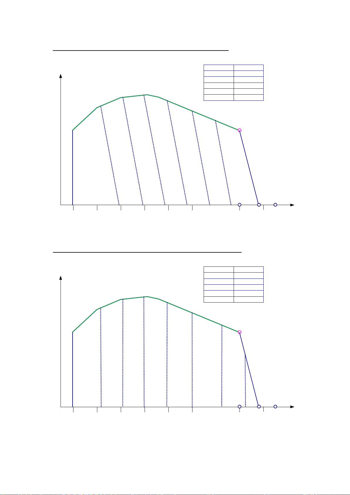
Perkins Engines Company ltd Confidential Green Draft 02 Nov 2004
Example Governing1 - showing droop and HSG slopes approximately equal
Flywheel
Torque
HILL
HIUL
D
R
O
O
P
800 1800
2200
Example Governing 2 – Showing isochronous droop but with a shallow HSG slope
Flywheel
Torque
HILL
HIUL
all speedgovernor
all speedgovernor
2200RS
2200
2600
2354HI
7%Droop
RS
HILL
2200RS
2200
2600
2350HI
0%Droop
H
S
G
HIUL
HI
Speed
(RPM)
RS
DROOP = ISOCHRONOUS
H
S
G
HILL
800 1800
2200
Page 54 of 92 1104D and 1106D Electronic Application and Installation Guide
HIUL
HI
Speed
(RPM)
Page 55

Perkins Engines Company ltd Confidential Green Draft 02 Nov 2004
Auxillary Governor
It is possible to control the engine by the output shaft speed of another module. Perkins do
not offer a speed sensor for this component, nor is there a direct speed sensor input, however
this is for the following reasons:
• There are a wide variety of speeds to be measured
• Speed sensors output signals are low in amplitude and sensitive to electromagnetic
interference
• The engine is often not close to the output shaft to be measured, thus resulting in
poor quality speed signals
The recommended solution for this requirement is as follows
The speed measured close to the output shaft by a third party electronic control module,
which would give an engine speed demand to the engine, either using by switch the PTO
raise and lower buttons. The third party module could also incorporate a display and/or
operator control buttons. The electronic Application team can give advise on specifying and
selecting the third party electronic module for this function.
The advantage of this approach is that, although the initial cost of the additional module is
higher than a direct speed input, the cost of the additional components is reasonable and the
advantages in reliability and ease of commissioning outweigh the disadvantages.
Rating selection via Service Tool
Some engines will have the capability to run more than one power rating. If this is the case
then the highest allowed rating may be changed via the “rating” parameter on the
confitguration screen of the service tool. Note, however that the engine may not be running
the highest enabled speed due to the status of the mode switches or due to requests from
another electronic module on the machine over J1939 datalink.
Mode Switches
A mode is a performance characteristic in terms of power / torque, Droop and rated speed.
There are up to 4 modes configurable on the 1104D and 1106D engines, and these can be
selected in operation when the engine is running and on load.
The mode switches are of the Switch to Ground type and the ECM J1 pin connections are as
follows:
Function ECM - J1
connector
pin
assignment
Mode switch 1 46
Mode switch 2 39
The following table is an example of how the mode switches can be configured. The 2 switch
inputs provide a total of four possible combinations. Two ratings have been configured such
that if switch 2 is open the engine will run on the lower rating, and if the switch is closed it will
run on the higher rating. Switch 1 is configured such that if it is open then the droop on throttle
1 and 2 is 10%, which may be suitable for road operation in an agricultural tractor, for
example. When Switch 1 is closed, however, a tighter droop is applied which may be suitable
in “field” or “work” operation
Note that the highest rating available in the mode switch feature will be defined by the “rating”
parameter on the configuration screen of the service tool
Page 55 of 92 1104D and 1106D Electronic Application and Installation Guide
Page 56

Perkins Engines Company ltd Confidential Green Draft 02 Nov 2004
Example of mode switch configuration
Switch 2 Switch 1 Mode
No.
Open Open 1 100KW @ 2200 10 10 10
Open Closed 2 100KW @ 2200 5 2 0
Closed Open 3 120KW @ 2200 10 10 10
Closed Closed 4 120 KW @ 2200 5 5 0
Rating
Droop (%)
Throttle 1 Throttle 2 Tsc1
Rating and Droop changes requested via the J1939 datalink
It will be possible to select an alternative droop and alternative rating via the J1939 link,
instead of via the hardwired switch inputs.
This feature is still in development, although the messages to be used are outlined in the
J1939 datalink section of this applications and installation guide
Page 56 of 92 1104D and 1106D Electronic Application and Installation Guide
Page 57

Perkins Engines Company ltd Confidential Green Draft 02 Nov 2004
Variable Speed Fan
A Variable Speed Fan control system will be offered as a configurable option. The engine
ECM will determine the correct fan speed based on engine Intake Manifold Temperature and
Coolant Temperature. Fan speed may also be controlled using J1939 data link.
Hydraulic arrangements may be controlled using a 2A PWM output.
The OEM will need to consider the following operating parameters:
Fan Speed Requirements (Max, Min)
Control Valve operating current (Max 2A)
Control Valve operating frequency
Further information concerning variable speed fan control will be available in Sep 2005
Machine Security System
Contact your local electronic applications representative for more information.
Using the ET service tool.
The latest version of ET will be required to view or modify some of the 1106D engine software
parameters and features. It is important that the engineer regularly updates their service tool
to ensure compatibility. In addition it is the responsibility of the engineer to confirm software
release dates. During project engine development features may not be available or viewable
and may be dependant later software release dates.
Page 57 of 92 1104D and 1106D Electronic Application and Installation Guide
Page 58

Perkins Engines Company ltd Confidential Green Draft 02 Nov 2004
Datalink Support
There are 2 datalinks available for OEM connection to the engine. J1939 and Perkins Data
link (CDL). It is recognized, however that other CANbus standards (higher level protocols) do
exist and are used in off-highway applications, so some notes are also provided for users of
those standards.
SAE J1939
The SAE J1939 standard was initially developed for the US truck and bus industry. It has
been expanded and is now the most widely used datalink standard for industrial powertrains,
with compliance from almost all engine manufacturers and most transmission manufacturers.
Summary of Key J1939 Application Issues
This is a summary of some of the key points and answers to frequently asked questions
relating to design of a J1939 compatible network. It is intended to give a design overview and
does not in any way replace or contradict the recommendations contained in the SAE J1939
standard documents.
Physical layer
• The data rate is 250 KBits/sec
• Twisted pair cable, of a 120Ohm impedance characteristic, should be used throughout.
Note that most commercially available twisted pair cable is not suitable.
• It is recommended that this cable is shielded (as per J1939-11)and that the screen is
grounded at a central point in the network. Unshielded-twisted pair cable is used by some
machine manufacturers, however (as per J1939-15), offering lower cost but lower
immunity to electromagnetic noise.
• The bus is linear and should be terminated with 120-Ohm resistors at either end. It is a
common mistake to use one 60-Ohm resistor instead of two 120-Ohm resistors. This
does not work correctly however.
• Maximum bus length is 40m
• The terminating resistors should not be contained in Network Nodes
• Network nodes are connected to the bus via stubs of maximum recommended length 1
meter.
Network Layer
• J1939 recommends a bit sample point of 87% . This relatively late sample point gives
best compromise for immunity to noise and propagation delay. It does restrict the size of
the software jump width (SJW), however.
• All nodes should have the same bit timing
• Accurate bit timing is essential (4µs +/- 0.2%)
• It is recommended that the average bus load is not greater than 40%
• Hardware filtering (masking) of CAN messages should be used under high bus loads to
limit demands on processors.
• The Engine ECM always assumes a fixed address 0. It will not change it’s address in the
arbitration process described in J1939-81
• The multi-7packet protocol (described in J1339-21) is used for sending messages with
more than 8 bytes of data. In the Perkins application this will be used principally for the
diagnostic messages DM1 and DM2.
• Information may be broadcast, at regular intervals, or requested. For example the engine
will broadcast its “current speed” every 20ms but it will only send “hours run “ information
if another node requests it.
Application Layer
• The messages (PGN’s)supported by Perkins ECM are only a subset of the messages
described in J1939-71 and J1939-73
Page 58 of 92 1104D and 1106D Electronic Application and Installation Guide
Page 59

Perkins Engines Company ltd Confidential Green Draft 02 Nov 2004
• Some PGN’s may be partially supported i.e. only those bytes for which the ECM has valid
data will be supported.
• Unsupported data bytes are generally sent as FF (hex) and incorrect or invalid
information is sent as FE.
Page 59 of 92 1104D and 1106D Electronic Application and Installation Guide
Page 60

Perkins Engines Company ltd Confidential Green Draft 02 Nov 2004
(
p
A
J1939 Supported Parameters Quick reference SummaryTable
PGN
Section of SAE
J1939 Document
71 0 0
71
71
71
71 57344 E000
71
71 61441
71
71 61443 F003
71
71
71
71
71
71
71
71
71 65174 FE96
71
71
71
71
71 65241 FED9
71
71
71
71
71
71
71
71
71
71
71
71
71
71
71
71
71
71
PGN (decimal)
(Hexidecimal)
PGN description
Torque Speed Control (Tsc1)
Cab Message 1 (CM1)
Electronic Brake Controller 1
EEC2
TurboWastegate
Fan Drive
Aux Discrete IO State
Parameter
roposed but may not yet be
available / fully validated )
r
Requested Torque / Torque Limit
Requested Speed / Speed Limit
Override Control Modes
r
Requested Percent Fan Speed
uxillary Engine Shutdown Switch
t
Percent load at current speed
Accelerator Pedal 1 Low Idle Switch
Accelerator Pedal 2 Low Idle Switch
Accelerator Pedal Position 1
Accelerator Pedal Position 2
Engine Speed
Engine Retarder Torque Mode
Actual Engine Percent Torque
t
Turbo1 Wastegate Drive
t
Fan Drive States
Estimated Percent Fan Speed
t
Aux IO discrete channel_1
Aux IO discrete channel_2
Aux IO discrete channel_3
Aux IO discrete channel_4
Aux IO discrete channel_5
Aux IO discrete channel_6
Aux IO discrete channel_7
Aux IO discrete channel_8
Aux IO discrete channel_9
Aux IO discrete channel_10
Aux IO discrete channel_11
Aux IO discrete channel_12
Aux IO discrete channel_13
Aux IO discrete channel_14
Aux IO discrete channel_15
Aux IO discrete channel_16
Aux IO Analog channel_1
Aux IO Analog channel_2
parameters in italics are
Receive /
ransmit
Page 60 of 92 1104D and 1106D Electronic Application and Installation Guide
Page 61

Perkins Engines Company ltd Confidential Green Draft 02 Nov 2004
(
p
PGN
Section of SAE
J1939 Document
PGN (decimal)
71 65242 FEDA
71
71
71 65243 FEDB
71
71 65247 FEDF
71
71 65251 FEE3
71
71
71
71
71
71
71
71
71
71
71
71
71 65252 FEE4
71
71 65253 FEE5
71
71
71
71 65259 FEEB
71
71
71
71
71 65260 FEEC
71
71 65262 FEEE
71
71
71
71 65264 FEF0
71
71
71
71
71
71 65266 FEF2
71
(Hexidecimal)
PGN description
Software Identification
Engine Fluid Level_Pressure_2
EEC3
EngineConfig
Shutdown
Engine Hours Revolutions
FuelConsumption
Component Identifier
Vehicle Identification
Engine Temp
EngineFluidLevel_Pressure
Power Take Off Info (PTO)
Fuel Economy
Parameter
parameters in italics are
roposed but may not yet be
available / fully validated )
Receive /
t
Software Identification
Number of software ID fields
t
Injector Metering Rail1 Pressure
t
Engine Desired Operating Speed
t
Engine Speed At Idle Pt1
Percent Torque At Idle Pt1
Engine Speed At Pt2
Percent Torque At Pt2
Engine Speed At Pt3
Percent Torque At Pt 3
Engine Speed at pt4
Percent Torque at pt4
Engine Speed at pt5
Percen Torque at pt5
Engine speed at high idle pt6
Reference Engine Torque
t
Wait To Start Lamp
t
Total Engine Hours
t
Total Fuel Used
t
Make
Model
Serial Number
Unit Number
t
Vehicle Identification Number
t
Engine Coolant Temperature
t
Engine Oil Pressure
t
PTO Set Switch
PTO resume Swich
PTO Enable Switch
PTO coast / Decelerate Switch
PTO accelerate Switch
t
Fuel Rate
ransmit
Page 61 of 92 1104D and 1106D Electronic Application and Installation Guide
Page 62

Perkins Engines Company ltd Confidential Green Draft 02 Nov 2004
(
p
A
A
A
A
A
A
A
A
A
A
PGN
Section of SAE
J1939 Document
PGN (decimal)
(Hexidecimal)
71 65270 FEF6
71
71
71
71 65165 FE8D
71
71
71a 64967 FDC7
71a
71a
71a
71a
71a 64971 FDCB
71a
71a
71a
71a
73 * *
73
73
73
73
73
73
73
73 * *
73
73
73
73
73
73
73
73 * *
73
21 * *
21
21 * *
21
21 * *
21
21
21 * *
Parameter
parameters in italics are
roposed but may not yet be
PGN description
InletExhaustCond
VehicleElectricalPower
available / fully validated )
t
Intake Manifold Temp
Boost Pressure
ir Inlet pressure
t
Electrical Potential
Battery Potential Switched
Off highway engine control
selection state
lternate Rating Select State
lternate Droop Accelerator 1 Select State
lternate Droop Accelerator 2 Select State
lternate Droop Remote Accelerator Select
State
Off highway engine control
selection (OHECS)
DM1 (active codes)
DM2 (logged codes)
lternate Rating Select
lternate Droop Accelerator 1 Select
lternate Droop Accelerator 2 Select
lternate Droop Remote Accelerator
t
Protect Lamp Status
Amber Lamp Status
Red Lamp Status
Spn
Fmi
Oc
Spn Conversion Method
t
Protect Lamp Status
mber Lamp Status
Red Lamp Status
Spn
Fmi
Oc
Spn Conversion Method
DM3 (request to clear logged
codes)
Transport Protocol (TP_DT)
Transport protocol (TP_CM)
Acknowledge (ACK and NACK)
Request PGN
r
Request To Clear Logged Fault Codes
t/r
TP_DT
t/r
BAM and RTS
t
PGN number
Control Byte
r
ransmit
Receive /
Page 62 of 92 1104D and 1106D Electronic Application and Installation Guide
Page 63

Perkins Engines Company ltd Confidential Green Draft 02 Nov 2004
(
p
PGN
Section of SAE
J1939 Document
21
PGN (decimal)
(Hexidecimal)
PGN description
Parameter
roposed but may not yet be
available / fully validated )
Requested PGN
parameters in italics are
ransmit
Receive /
Page 63 of 92 1104D and 1106D Electronic Application and Installation Guide
Page 64
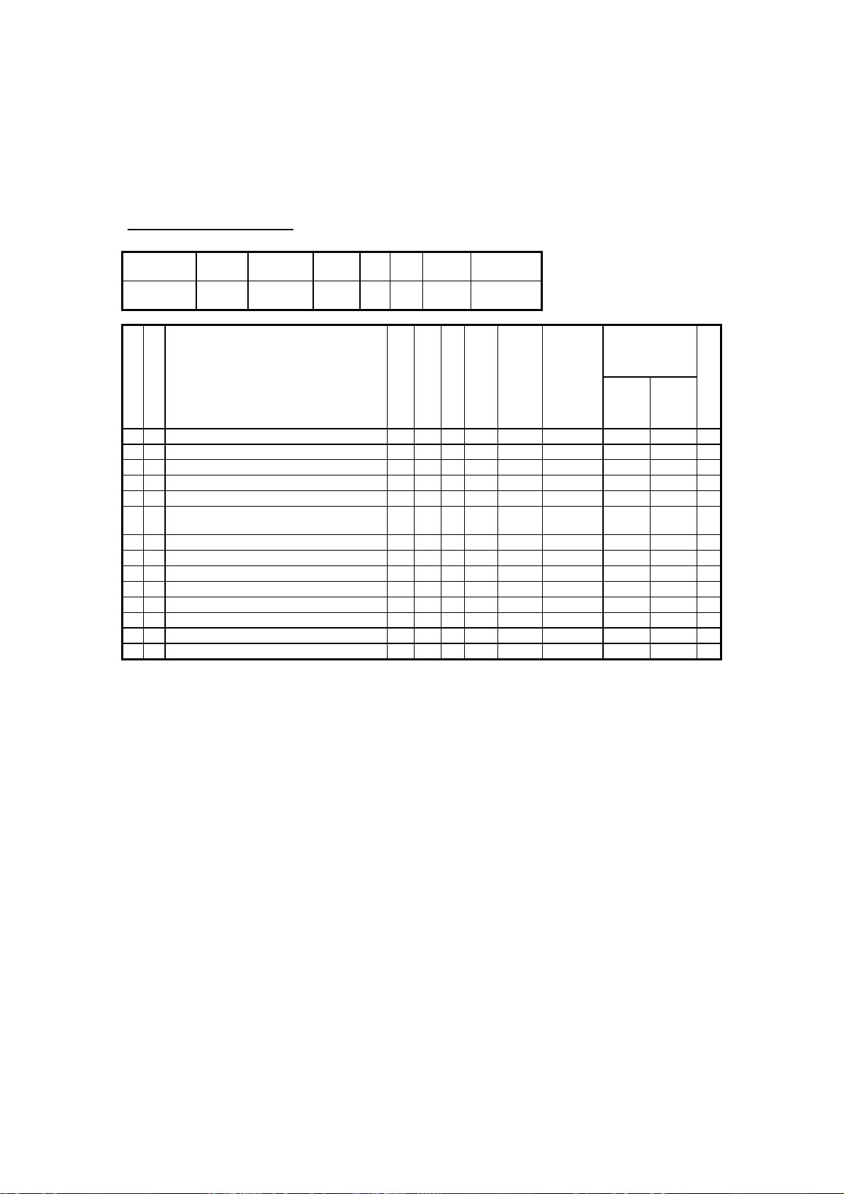
Perkins Engines Company ltd Confidential Green Draft 02 Nov 2004
J1939 Parameters – Detailed Descriptions
Note: The PGN numbers are written in some documents in decimal form (e.g.61444). This
document will use the Hexidecimal form (e.g. F004) as it is easier to remember and simpler to
decode when using tools to analyse traffic on the CAN J1939 bus.
Torque Speed Control (TSC1)
Identifier Rate
0C 00 00 xx 10 000000 3 0 0 See
S
R
e
e
n
c
d
e
i
v
e
X Override Control Mode (spn 695)
X
X
X
X Override Control Mode Priority (spn 897)
X
X
X
X
X Requested Speed / Speed Limit (spn 898)
X Requested Torque / Torque Limit
(msec)
Parameter name B
Override Disabled 00
Speed Control 01
Torque Control 10
Speed/Torque Limit Control 11
Requested Speed Control Conditions (spn
696)
Highest Priority 00 A
High Priority 01 A
Medium Priority 10 A
Low Priority 11 A
Not Defined 7..8
PGN Default
The Torque/Speed Control #1 (TSC1) PGN allows other electronic devices to control the
engine speed.
Although originally designed by the SAE for truck applications as a temporary means for the
transmission to override engine speed during gearshifts, this PGN is now widely used as a
permanent means of controlling the engine speed. It is particularly common in machines that
have complex hydraulic systems.
This is a powerful feature, but special care must be taken by the OEM with the
implementation of TSC1 to ensure that the speed demanded of the engine is one that is safe
and appropriate for the current operating conditions of the engine. It is the responsibility of the
ECM to ensure that this is so and to perform the necessary risk assessment validation of the
software of electronic modules on the application that are transmitting TSC1 speed demand
messages to the engine.
TSC1 Configuration
Tsc1 will always be available (it does not need to be configured to be ENABLED in the
service tool)
In addition, Tsc1 may be configured to be a “continuous speed limit/ request”. In this case the
• TSC1 –Transient Engine Speed Limit / Request
• TSC1 - Continuous Speed Limit / Request
Priority
R1 DP Source Destination
notes
B
L
y
i
e
t
t
n
e
1 1 2
3 2
5 2 A
2 1 16 Rpm 0.125 0 8032
4 1 8 % 1 -125 +125 B
g
t
h
00
S
U
Resolution
t
n
(unit/bit)
a
i
t
t
e
s
Range
Min Max
N
o
t
e
Page 64 of 92 1104D and 1106D Electronic Application and Installation Guide
Page 65

Perkins Engines Company ltd Confidential Green Draft 02 Nov 2004
In addition to these options, it is also possible to specify what droop value applies to the
engine speed request. This will operate in the same was as for the direct analogue / PWM
and throttle position switch inputs.
TSC1 as Transient Speed Limit / Request
The ECM will allow other modules to request or limit engine speed for any period. The TSC1
message will override any other speed demand such as PWM throttle pedal.
End of Transmission – fault detection
The ECM needs to differentiate between the end of a transmission by another controller and
an intermittent failure. The ECM expects, therefore, that when a controller no longer wished to
demand engine speed then it will terminate with at least one message with the control
override bits set to 00. If the engine sees that TSC1 messages have stopped, for 90ms, but
have not been terminated correctly then the ECM will recognize this as a fault and will not
accept any speed demand requests for the remainder of the key cycle.TSC1 as Permanent
speed demand
Source address requirements
The ECM will accept messages from modules with any source address (i.e. TSC1 messages
do not necessarily have to be sent by the transmission). The destination address does have
to be 00 for the messages to be accepted by the engine however.
TSC1 as Continuous Speed Limit / Request
If TSC1 is to be the primary means of controlling the engine speed or as a method of
continuously limiting engine speed, then the ECM may be configured to
raise a fault code if a valid Tsc1 message is not received by the time that engine speed
reaches 500rpm of the keyswitch being turned on. This will allow for the normal start up time
of other electronic modules.
TSC1 - Feature Summary Table
Function TSC1 –
Transient
TSC1 –
Continuous
(default)
Speed request Yes Yes
Speed limit Yes Yes
Torque request No No
Torque Limit (temporary) Yes Yes
Fault Detection – 90ms Timeout Yes Yes
Fault Detection – Message present at start No Yes
Accepts TSC1 messages from several sources
No No
simultaneously
Note A: The ECM does not prioritize or arbitrate between speed request or limits from more
than one source and so this situation may result in erratic engine operation. The OEM must
ensure that TSC1 messages are not sent from more than one source at a time.
Note B: Support for the “Torque limiting” aspect of TSC1 has been added, although this may
only be used for temporary conditions, such as during a gear change.
Cab Message 1 (CM1)
Identifier Rate
18E000xx 1000 E000 6 0 0 - 00
(msec)
PGN Default
Priority
R1 DP Source Destination
Page 65 of 92 1104D and 1106D Electronic Application and Installation Guide
Page 66
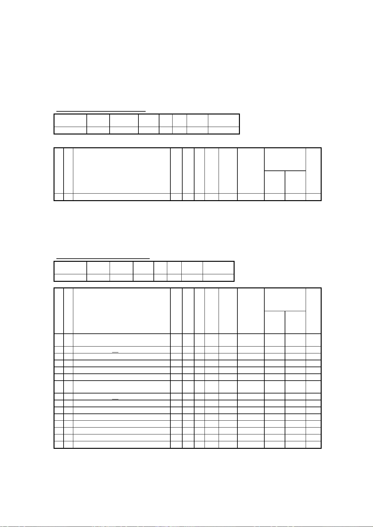
Perkins Engines Company ltd Confidential Green Draft 02 Nov 2004
Not currently supported. This PGN may be used in applications where then engine ECM
controls the speed of a fan (e.g. electronically controlled viscous fan or hydraulic fan). The
parameter Requested Percent Fan Speed (SPN 986) will be sent to the engine to another
module (e.g. air conditioning or hydraulic oil temperature) to communicate its need for
cooling.
Will be implemented if referenced in Fan Control document (not available for job 1)
Electronic Brake Controller 1 (EBC1)
Identifier Rate
(msec)
18F00100 100 F001 6 0 0 - 00
PGN Default
R1 DP Source Destination
Priority
S
R
Parameter name B
e
e
n
c
d
e
i
v
e
Auxillary Engine Shutdown Switch (970) 4 5 2
X
B
L
S
U
Resolution
y
i
e
t
n
(unit/bit)
t
t
n
a
i
e
g
t
t
t
e
s
h
Range
Min Max
N
o
t
e
This message may be sent to the engine to request it to stop running, without turning off the
ignition keyswitch. This will be a normal stop and is not expected to be a safety related fail
safe stop function.
Electronic Engine Controller 2 (EEC2)
Identifier Rate
0C F0 03 00 50 00F003 3 0 0 00 -
S
R
e
e
n
c
d
e
i
v
e
X
X
X
X
X
Accelerator Pedal Kickdown Switch
X
X
X
X
X
X
X
X
(msec)
Parameter name B
Accelerator Pedal Low Idle Switch 1 (spn
558)
Accelerator pedal not
Accelerator pedal in low idle condition
Error indicator
Not available or not installed
Accelerator Pedal Low Idle Switch 2 (spn
2970)
Accelerator pedal not
Accelerator pedal in low idle condition
Error indicator
Not available or not installed
Accelerator Pedal Position 1 (spn 91)
Percent Load at Current Speed (spn 92)
Remote Accelerator
Accelerator Pedal Position 2 (spn 29)
PGN Default
in low idle condition 00
in low idle condition 00
Priority
R1 DP Source Destination
B
L
S
y
i
e
t
t
t
n
a
e
1 1 2 C
01
10
11
3 2
1 7 2 A
01
10
11
2 1 8
3 1 8
4 1 8
5 1 8
g
t
t
e
h
U
Resolution
n
(unit/bit)
i
t
s
% .4 0 100
% 1 0 125 B
% .4 0 100 A,
Range
Min Max
N
o
t
e
Note A: Accelerator pedal low idle 2 and accelerator pedal position 2 are new parameters
only recently defined by The SAE. The start byte / bit of accelerator pedal low idle switch 2 is
still to be defined.
Page 66 of 92 1104D and 1106D Electronic Application and Installation Guide
Page 67
Perkins Engines Company ltd Confidential Green Draft 02 Nov 2004
Note B: Percent load at current speed. Parameter is not accurate at low loads nor during
transient conditions.
Note C: When there is discrepancy between the pedal position and the idle validation switch
position, then the Accelerator Pedal Low Idle Switch parameter will be transmitted as 102
(error) and the accelerator pedal position will be transmitted as FE16 (error). If however, a
pedal is not configured, then it will be sent as not supported. This will apply to both
accelerator 1 and accelerator 2. Note also that the name “accelerator pedal” is not always
accurate for off highway machines. Accelerator pedal 1 refers to any pedal, lever or other
device that uses either the Analogue 1 or PWM throttle 1 input. Likewise, Accelerator pedal
position 2 refers to any device that uses the analogue throttle 2 input.
Electronic Engine Controller 1 (EEC1)
Identifier Rate
0C F0 04 00 20 00F004 3 0 0 00
S
R
Parameter name B
e
e
n
c
d
e
i
v
e
Engine Torque Mode
Low Idle Governor 0000 B
X
Accelerator Pedal 1 0001 B
X
Cruise Control 0010
PTO Governor 0011 B
X
Road Speed Governing
ASR Control
X
Transmission Control
ABS Control
X
Torque Limiting
X
High Speed Governor
Brake System
Not defined (1011 – 1101)
Other
Not available
Not Defined
Drivers Demand Engine - Percent Torque
X
Actual Engine - Percent Torque
X
Engine Speed
Source Address of Controlling Device for
Engine Control
Engine Starter Mode
PGN Default
(msec)
Priority
R1 DP Source Destination
B
L
S
y
i
e
t
t
t
n
a
e
1 1 4 B
0100
0101
0110
0111
1000
1001
1010
1110
1111
5..8
2 1 8
3 1 8
4 1 16
6 1 8
7 1 4
g
t
t
e
h
U
Resolution
n
(unit/bit)
i
t
s
B
B
B
% 1
% 1
rpm .125
None 1 0 253
Range
Min Max
N
o
t
e
Note A: The J1939 standard describes the frequency of transmission of this PGN as engine
speed dependant. The ECM actually transmits the message every 20ms, however,
irrespective of engine speed
Engine torque mode - is not currently available although it intended to be supported in future
software. Please contact an Electronic Applications engineer before using this parameter.
Turbocharger Wastegate (TCW)
Identifier Rate
(msec)
PGN Default
R1 DP Source Destination
Priority
Page 67 of 92 1104D and 1106D Electronic Application and Installation Guide
Page 68
Perkins Engines Company ltd Confidential Green Draft 02 Nov 2004
18FE9600 100 FE96 6 0 0 00 -
S
R
Parameter name B
e
e
n
c
d
e
i
v
e
Turbocharger 1 Wastegate Drive (spn
X
1188)
Turbocharger 2 Wastegate Drive
Turbocharger 3 Wastegate Drive
Turbocharger 4 Wastegate Drive
Turbocharger Wastegate Act Control
Pressure
B
L
S
U
Resolution
y
i
e
t
n
(unit/bit)
t
t
n
a
i
e
1 1 8
2 1 8
3 1 8
4 1 8
5 1 8
g
t
t
t
e
s
h
% 0.4 0 100 A
Range
Min Max
N
o
t
e
Note A: The J1939 specification states that “ Position of the wastegate drive. A value of 0%
represents fully closed and a value of 100% represents fully open”. The implementation,
however is that this value directly equates to the PWM duty cycle of the wastegate drive.
Fan Drive (FD)
Identifier Rate
18FEBD00 1000 FEBD 6 0 0 00 -
(msec)
PGN Default
Priority
R1 DP Source Destination
Not currently supported. This PGN may be used in applications where then engine ECM
controls the speed of a fan (e.g. electronically controlled viscous fan or hydraulic fan). The
parameter Estimated Percent Fan Speed (spn 975) will be used by the engine to give
feedback of the current fan speed conditions to other modules on the application. In addition
the parameter Fan Drive State (spn 977) will give the status of which parameter is controlling
the fan speed: Engine Coolant Temperature, Engine Air Temperature, or a fan speed request
via J1939.
XX OL: Check that this is referenced n the fan specification – if so then will be supported in
june 05 dev software (post job 1 production)
Auxillary Discrete IO state (AUXIO)
Identifier Rate
18FED900 Note A FED9 6 0 0 00 -
S
R
e
e
n
c
d
e
i
v
e
X Auxiliary I/O #04 (spn 704)
X Auxiliary I/O #03 (spn 703)
X Auxiliary I/O #02 (spn 702)
X Auxiliary I/O #01 (spn 701)
X Auxiliary I/O #08 (spn 708)
X Auxiliary I/O #07 (spn 707)
X Auxiliary I/O #06 (spn 706)
X Auxiliary I/O #05 (spn 705)
Auxiliary I/O #12 (spn 712)
X Auxiliary I/O #11 (spn 711)
X Auxiliary I/O #10 (spn 710)
(msec)
Parameter name B
PGN Default
Priority
R1 DP Source Destination
B
L
S
U
Resolution
y
i
e
t
n
(unit/bit)
t
t
n
a
i
e
1 1 2 B
1 3 2 B
1 5 2 B
1 7 2 B
2 1 2 B
2 3 2 B
2 5 2 B
2 7 2 B
3 1 2 B
3 3 2 B
3 5 2 B
g
t
t
t
e
s
h
Range
Min Max
N
o
t
e
Page 68 of 92 1104D and 1106D Electronic Application and Installation Guide
Page 69

Perkins Engines Company ltd Confidential Green Draft 02 Nov 2004
X Auxiliary I/O #09 (spn 709)
Auxiliary I/O #16 (spn 716)
Auxiliary I/O #15 (spn 715)
X Auxiliary I/O #14 (spn 714)
X Auxiliary I/O #13 (spn 713)
X Auxiliary I/O Channel #1 (spn 1083)
X Auxiliary I/O Channel #2 (spn 1084)
3 7 2 B
4 1 2 B
4 3 2 B
4 5 2 B
4 7 2 B
5,6 1 16 0 64255 C
7,8 1 16 0 64255 C
Note A: The message will be sent at a frequency of 100ms, and additionally when any of the
supported switch inputs (spn’s 701 through 716) change state
This PGN will be used to transmit the status of all the customer side switch inputs, and two of
the analogue voltage inputs of the ECM, irrespective of whether the input is used by the ECM
for an application software feature.
The machine designer can use the spare inputs of the ECM, therefore, as additional input
channels for non engine systems
Note B: Each of the switch inputs is transmitted as 00 if it the switch is open (or not
connected) and 01 if it is closed.
The 2 “SWB” inputs below are “switch to battery”, meaning that when battery voltage is
applied to the pin then it will be “closed”. All the other switch inputs are switch to ground,
which means that when an input is at ground potential it will be “closed”
Note C: The analogue channels are scaled at 0.955Volts per bit with a 0.5V offset. For
example a voltage of 2.5Voltages would be transmitted as (2.5volts – 0.5 v offset)/0.000955
volts/bit = 2094
or 82E16
10
Table of Input pins to SPN’s
Input
name
ECM J1
Connector
J1939 SPN
Pin
SWG1 52 701
SWG2 51 702
SWG3 50 703
SWG4 49 704
SWG5 48 705
SWG6 47 706
SWG7 46 707
SWG8 45 708
SWG9 44 709
SWG10 39 710
SWG11 38 711
SWB1 37 713
SWB2 38 714
AIN_ACT5 55 1083
AIN_ACT4 56 1084
Software Identification (SOFT)
Identifier Rate
(msec)
18FEDA00 On Req FEDA 6 0 0 00 -
PGN Default
Priority
R1 DP Source Destination
Page 69 of 92 1104D and 1106D Electronic Application and Installation Guide
Page 70
Perkins Engines Company ltd Confidential Green Draft 02 Nov 2004
R
Parameter name B
e
e
n
c
d
e
i
v
e
Number of software identification fields
X
(spn 965)
X Software Identification (spn 234)
B
L
S
U
Resolution
y
i
e
t
n
(unit/bit)
t
t
n
a
i
e
1 1 8
2 1 N ASCII B
g
t
t
t
e
s
h
1 255 A
Range S
Min Max
Note A: The number of software identification fields will be transmitted as “02”
Note B: The software identification is ASCII text, with the fields delimited by a “*”
ASCII code as follows:
02 SWPN:1234556701*SWDT:MAY05*
Software part number (SWPN) will be of the form 123456701
Software release date (SWDT) will be of the form MAY05
Note that as this PGN has more than 8 bytes of data then the transport protocol will be used
as described below.
Engine Fluid Level / Pressure 2 (EFL/P2)
Identifier Rate
18FEDB00 500 FEDB 6 0 0 00 -
S
R
e
e
n
c
d
e
i
v
e
Injector Control Pressure
X
Injector Timing Rail 1 Pressure
Injector Metering Rail 2 Pressure
(msec)
Parameter name B
Injector Metering Rail 1 Pressure
(spn157)
PGN Default
Priority
R1 DP Source Destination
B
L
S
U
Resolution
y
i
e
t
n
(unit/bit)
t
t
n
a
i
e
1 1 16
3 1 16
5 1 16
7 1 16
g
t
t
t
e
s
h
Mpa 1/256Mpa/Bit 0 251
Range
Min Max
Priority
R1 DP Source Destination
B
L
S
y
i
e
t
t
t
n
a
e
1 1 8 % 1 -125 +125
2 1 16
4 1 8
g
t
t
e
h
U
Resolution
n
(unit/bit)
i
t
s
Rpm .125 0 8031 A
Ratio 0 250
Range
Min Max
Electronic Engine Controller 3 (EEC3)
Identifier Rate
18 FE DF 00 250 FEDF 6 0 0 00 -
S
R
e
e
n
c
d
e
i
v
e
Nominal friction – Percent Torque
X
(msec)
Parameter name B
Engine´s Desired Operating Speed (spn
515)
Engine´s Operating Speed Asymmetry
Adjustment
PGN Default
Note A: Engine desired operating speed will be the speed at which the engine would run if all
load were removed and current speed demand conditions maintained.
N
o
t
e
N
o
t
e
N
o
t
e
Page 70 of 92 1104D and 1106D Electronic Application and Installation Guide
Page 71

Perkins Engines Company ltd Confidential Green Draft 02 Nov 2004
This is not the same as the implementation for tier 2 product but the change has been
implemented to make the parameter more relevant to customers who need to determine how
far and how rapidly the engine is lugging back. One effect will be that in many applications
where there are high parasitic loads, the engine speed will never actually reach it’s desired
operating speed.
Page 71 of 92 1104D and 1106D Electronic Application and Installation Guide
Page 72

Perkins Engines Company ltd Confidential Green Draft 02 Nov 2004
Engine Configuration (EC)
Identifier Rate
See Note A See Note B FEE3 6 0 0 00 -
S
R
e
e
n
c
d
e
i
v
e
X Engine Speed at Idle, Point 1 (spn 118)
X Percent Torque at Idle, Point 1 (spn 539)
X Engine Speed at Point 2 (spn 528)
X
Percent Torque at Point 2 (spn 540)
X
Engine Speed at Point 3 (spn 529)
X
Percent Torque at Point 3 (spn 541)
X
Engine Speed at Point 4 (spn 530)
X
Percent Torque at Point 4 (spn 542)
X
Engine Speed at Point 5 (spn 531)
X
Percent Torque at Point 5 (spn 543)
X
Gain (KP) of the Endspeed Governor
X Reference Engine Torque (spn 544)
(msec)
Parameter name B
Engine Speed at High Idle, Point 6 (spn
532)
Maximum Momentary Engine Override
Speed, Point 7
Maximum Momentary Override Time
Limit
Requested Speed Control Range Lower
Limit
Requested Speed Control Range Upper
Limit
Requested Torque Control Range Lower
Limit
Requested Torque Control Range Upper
Limit
PGN Default
Priority
R1 DP Source Destination
B
L
S
U
Resolution
y
i
e
t
n
(unit/bit)
t
t
n
a
i
e
1 1 16 Rpm 0.125 0 8031
3 1 8 % 1 -125 +125
4 1 16 Rpm 0.125
6 1 8
7 1 16
9 1 8
10 1 16
12 1 8
13 1 16
15 1 8
16 1 16
18 1 16
20 1 16 Nm 1 0 64255 C
22 1 16
24 1 8
25 1 8
26 1 8
27 1 8
28 1 8
g
t
t
t
e
s
h
1 -125
%
0.125 0
Rpm
1 -125
%
0.125 0
Rpm
1 -125
%
0.125 0
Rpm
1 -125
%
0.125 0
Rpm
0.0007813 0
%/rpm
0.125
Rpm
0.1
S
10
Rpm
10
Rpm
1
%
1
%
Range
Min Max
0
8031 D
+125 D
8031
+125
8031
+125
8031
+125
8031 D
0 8031
0 25
0 2500
0 2500
-125 +125
-125 125
N
o
e
50.2
This PGN defines several points on the torque curve (rating) that is active in the engine. The
values will change if a different torque curve is selected or to reflect if the engine is derating
e.g. due to excessive engine temperature.
Note A: As this PGN is more than 8 bytes long, it will always be transmitted via the transport
protocol
Note B: This PGN is sent every 5 seconds but also whenever there is a change in active
torque limit map.
Note C: Engine reference torque is the advertised bare engine torque of the highest “enabled”
rating in the box. That is the highest rating that can be selected via mode switches or J1939,
whilst the engine is running.
Note D: As both point 2 and point 6 are supported, and Gain (Kp) of Endspeed Governor is
not, the support of this message conforms to Engine Configuration Characteristic Mode 1 as
described in the J1939-71 specification
t
Page 72 of 92 1104D and 1106D Electronic Application and Installation Guide
Page 73

Perkins Engines Company ltd Confidential Green Draft 02 Nov 2004
Shutdown (SHUTDOWN)
Identifier Rate
18 FE E4 00 1000 FEE4 6 0 0 00 -
S
R
e
e
n
c
d
e
i
v
e
Idle shutdown has shut down engine
Idle shutdown driver alert mode
Idle shutdown timer override
Idle shutdown timer state
Idle shutdown timer function
A/C high pressure fan switch
Refrigerant low pressure switch
Refrigerant high pressure switch
X Wait to start lamp (spn 1081)
X
X
Engine protection system timer override
Engine protection system timer state
Engine protection system configuration
(msec)
Parameter name B
Off 00
On 01
Engine protection system has shut down
engine
Engine protection system approaching
shutdown
PGN Default
Priority
R1 DP Source Destination
B
L
S
y
i
e
t
t
t
n
a
e
1 1 2
3 2
5 2
7 2
7 2
3 1 2
3 2
5 2
4 1 2
5 1 2
3 2
5 2
7 2
7 2
g
t
t
e
h
U
n
i
t
s
Resolution
(unit/bit)
Range
Min Max
N
o
t
e
Page 73 of 92 1104D and 1106D Electronic Application and Installation Guide
Page 74
Perkins Engines Company ltd Confidential Green Draft 02 Nov 2004
Priority
R1 DP Source Destination
B
L
S
U
Resolution
y
i
e
t
n
(unit/bit)
t
t
n
a
i
e
1 1 32 Hr .05 0 210,554,060
5 1 32 Rev 1000 0 4,211,081,215,000
g
t
t
t
e
s
h
Range
Min Max
Engine Hours / Revolutions (HOURS)
Identifier Rate
18 FE E5 00 1000
S
R
e
e
n
c
d
e
i
v
e
X Total engine hours (spn 247)
Total engine revolutions
(msec)
Note A
Parameter name B
PGN Default
FEE5 6 0 0 00 -
Note A: The SAE defines this PGN as being sent on request. There are some gages and
displays on the market however, which require this to be broadcast. This message will be
broadcast at a low update rate, therefore, to ensure compatibility with these devices.
Fuel Consumption
Identifier Rate
18 FE E9 00 On Req 00FEE9 6 0 0 00 -
S
R
Parameter name B
e
e
n
c
d
e
i
v
e
Trip fuel
X Total fuel used (spn 250)
(msec)
PGN Default
Priority
R1 DP Source Destination
B
L
S
U
Resolution
y
i
e
t
n
(unit/bit)
t
t
n
a
i
e
1 1 32 L .5 0 2,105,540,607
5 1 32 L .5 0 2,105,540,607
g
t
t
t
e
s
h
Range
Min Max
Note A: This parameter is not a direct measurement. It is calculated from standard test fuel at
standard test temperatures. The characteristics of most fuels in the field will differ from the
test fuel, particularly at very high or very low temperatures. It is recommended, therefore, that
this value is taken to be an indication only of the fuel used by an engine.
Component ID (CI)
Identifier Rate
18 FE EB 00 On Req 00FEEB 6 0 0 00 -
S
R
Parameter name B
e
e
n
c
d
e
i
v
e
X Make (spn 586)
X Model (spn 587)
X Serial Number (spn 588)
Unit Number (spn 233)
(msec)
PGN Default
Priority
R1 DP Source Destination
B
L
S
y
i
e
t
t
t
n
a
e
ASCII None A
ASCII None A
ASCII None A
g
t
t
e
h
ASCII None
U
n
i
t
s
Resolution
(unit/bit)
Range
Min Max
Note A: All these parameters are supported as ASCII text delimited by “*”
N
o
t
e
N
o
t
e
N
o
t
e
Page 74 of 92 1104D and 1106D Electronic Application and Installation Guide
Page 75
Perkins Engines Company ltd Confidential Green Draft 02 Nov 2004
“Make” will be transmitted as “CTRPL”
“Model” will be transmitted in the form “1106D” or “1104D” or “1104D” or “1106D”
“Serial Number” will be the engine serial number as marked on the nameplate of the engine
Vehicle Identification (VI)
Identifier Rate
(msec)
18FEEC00 On Req FEEC 0 0 00 -
PGN Default
Priority
R1 DP Source Destination
This PGN may be requested from the ECM but currently the message will simply contain the
ASCII text “NOT PROGRAMMED”.
Engine Temperature (ET1)
Identifier Rate
18 FE EE 00 1000 FEEE 6 0 0 00 -
S
R
e
e
n
c
d
e
i
v
e
X Engine Coolant Temperature (spn 110)
Fuel Temperature
Engine Oil Temperature
(msec)
Parameter name B
Turbo Oil Temperature
Engine Intercooler Temperature
Engine Intercooler Thermostat Opening
PGN Default
Priority
R1 DP Source Destination
B
L
S
U
Resolution
y
i
e
t
n
(unit/bit)
t
t
n
a
i
e
1 1 8 deg C 1 -40 210
2 1 8
3 1 16
5 1 16
7 1 8
8 1 8
g
t
t
t
e
s
h
deg C 1 -40 210
deg C .03125 -273 1735
deg C .03125 -273 1735
deg C 1 -40 210
% .4 0 100
Range
Min Max
N
o
t
e
Priority
R1 DP Source Destination
B
L
S
y
i
e
t
t
t
n
a
e
1 1 8 KPA 4 0 1000
2
3 1 8 %
4 1 8 KPA
5 1 16
7 1 8 KPA
8 1 8 %
g
t
t
e
h
U
Resolution
n
(unit/bit)
i
t
s
.4 0 100
4 0 1000
2 0 500
.4 0 100
Range
Min Max
N
o
t
e
Engine Fluid Level / Pressure (EFL/P1)
Identifier Rate
18 FE EF 00 500 FEEF 6 0 0 00 -
S
R
e
e
n
c
d
e
i
v
e
Fuel Delivery Pressure
Engine Oil Level
X
Engine Oil Pressure (spn 100)
Crankcase Pressure
(msec)
Parameter name B
Extended Crankcase Blow-by Pressure
Coolant Pressure
Coolant Level
PGN Default
PTO information (PTO)
Identifier Rate
18FEF000 100 FEF0 6 0 0 00 -
S
R
e
e
n
c
(msec)
Parameter name B
PGN Default
Priority
R1 DP Source Destination
B
L
S
U
Resolution
y
i
e
t
n
(unit/bit)
t
t
n
a
i
Range N
o
t
Page 75 of 92 1104D and 1106D Electronic Application and Installation Guide
Page 76

Perkins Engines Company ltd Confidential Green Draft 02 Nov 2004
d e
e g
i
v
e
Power Takeoff Oil Temperature (spn 90)
Power Takeoff Speed (spn 186)
Power Takeoff Set Speed (spn 187)
X
PTO Enable Switch (spn 980)
Remote PTO preprogrammed Speed
Control Switch (spn 979)
Remote PTO variable Speed Control
Switch (spn 978)
X
PTO set switch (spn 984)
X
PTO Coast / Decelerate Switch (spn 983)
X
PTO Resume Switch (spn 982)
X
PTO Accelerate Switch (spn 981)
1 1 8
2 1 16
4 1 16 Rpm
6 1 2
6 3 2
6 5 2
7 1 2
7 3 2
7 5 2
7 7 2
t
t
e
h
t s Min Max e
Rpm 0 8031
A
A
A
A
Note A: Some of the PTO mode switch inputs on the ECM have dual functions. For example,
one button provides both SET and LOWER functions and another button provides both
RAISE and RESUME functions. When the SET/LOWER button is pressed, both SPN 984 and
SPN 938 will go to the active state, for at least one message transmission.
Similarly, when the RAISE/RESUME button is pressed then both SPN 982 and SPN 981 will
go to the active state.
Page 76 of 92 1104D and 1106D Electronic Application and Installation Guide
Page 77
Perkins Engines Company ltd Confidential Green Draft 02 Nov 2004
(msec)
PGN Default
Priority
R1 DP Source Destination
B
L
S
U
y
i
e
t
n
t
t
n
a
i
e
1 1 16 L/hr .05 0 3212 A
3 1 16 km/kg 1/512 0 125.5
5 1 16 km/kg 1/512 0 125.5
7 1 8 % .4 0 100
g
t
t
t
e
s
h
Resolution
(unit/bit)
Range
Min Max
Fuel Economy (LFE)
Identifier Rate
18 FE F200 100 FEF2 6 0 0 00 -
S
R
Parameter name B
e
e
n
c
d
e
i
v
e
X Fuel Rate (spn 183)
Instantaneous Fuel Economy
Average Fuel Economy
Throttle Position
Note A: This parameter is not a direct measurement.. It is recommended, therefore, that this
value is taken to be an indication only of the fuel quantity injected
Inlet / Exhaust Conditions (IC)
Identifier Rate
18 FE F6 00 500 FEF6 6 0 0 00 -
S
R
e
e
n
c
d
e
i
v
e
X
X
X
(msec)
Parameter
name
Particulate
Trap Inlet
Pressure
Boost
Pressure
Intake
Manifold
Temperature
Air Inlet
Pressure
Air Filter
Differential
Pressure
Exhaust Gas
Temperature
Coolant
Filter
Differential
Pressure
B
y
t
e
1 1 8 kPa .5 0 125
2 1 8
3 1 8 deg
4 1 8 kPa
5 1 8 kPa
6 1 16 deg
8 1 8 kPa
PGN Default
Priority
B
L
i
e
t
n
g
t
h
R1 DP Source Destination
S
U
Resolution
t
n
(unit/bit)
a
i
t
t
e
s
kPa
2 0 500 B
1 -40 210
C
2 0 500 A
.05 0 12.5
.03125 -
C
.5 0 125
Range
Min Max
1735
273
N
o
t
e
Note A: Inlet air pressure will be supported as the absolute pressure as measured by the inlet
manifold pressure sensor.
Note B: Boost pressure will be calculated from inlet manifold temperature. Boost pressure will
never be transmitted as a negative number, even though a slight depression at the inlet is
possible for some engines when running at low idle speed.
Vehicle Electrical Power (VEP)
Identifier Rate
(msec)
18 FE F7 00 1000 FEF7 6 0 0 00 -
PGN Default
Priority
R1 DP Source Destination
N
o
t
e
Page 77 of 92 1104D and 1106D Electronic Application and Installation Guide
Page 78
Perkins Engines Company ltd Confidential Green Draft 02 Nov 2004
S
R
Parameter name B
e
e
n
c
d
e
i
v
e
Net Battery Current
Alternator Potential (Voltage)
X Electrical Potential (Voltage)
X Battery Potential (Voltage), Switched
B
L
S
U
Resolution
y
i
e
t
n
(unit/bit)
t
t
n
a
i
e
1 1 16 Amp 1 -125 125
3 1 16 V .05 0 3212
5 1 16 V .05 0 3212 A
7 1 16 V .05 0 3212 A
g
t
t
t
e
s
h
Range
Min Max
N
o
t
e
Note A: Electrical potential and battery potential parameters are both supported with the same
value, which is the voltage measured between the battery (+) and battery (-) terminals of the
ECM
Operator Primary Intermediate Speed (ISCS)
Identifier Rate
(msec)
18FDC800 1000 FDC8 6 0 0 00 -
PGN Default
Priority
R1 DP Source Destination
R
Parameter name B
e
e
n
c
d
e
i
v
e
X
Operator Primary Intermediate Speed
Select State (spn 2892)
Intermediate speed not requested 0000 A
Logical Position 1
X
X
Logical Position 2
X
Logical Position 3
X
Logical Position 4
X
Logical Position 5
X
Logical Position 6
X
Logical Position 7
X
Logical Position 8
X
Logical Position 9
X
Logical Position 10
X
Logical Position 11
X
Logical Position 12
X
Logical state 13, 14, 15 or 16
Reserved
X
Not available
B
L
S
U
Resolution
y
i
e
t
n
(unit/bit)
t
t
n
a
i
e
1 1 4
0010
0011
0100
0101
0110
0111
1000
1001
1010
1100
1101
1110
1111
g
t
h
t
e
0001
t
s
B
C
Range S
Min Max
N
o
t
e
This PGN is used to describe the logical state of the throttle position switch input (also known
as multi-position throttle switch).
Note A: “intermediate speed not requested” state is not supported. Note however, that on
most applications where throttle position switch is used, logical position 1 will be all four
switches in the open position and will equate to engine idle.
Note B: There are only 13 states available but 16 possible combinations of the 4 switch
inputs. No known application has used more than 10 states however, or is expected to use
more than 10 states in the future, so this is not envisaged that this will cause a problem. If 16
states are use then logical states 14, 15 and 16 will be transmitted as 13.
Page 78 of 92 1104D and 1106D Electronic Application and Installation Guide
Page 79

Perkins Engines Company ltd Confidential Green Draft 02 Nov 2004
Note C: If the throttle position switch is not configured on an application then the ECM will
send 1111
not available.
2
Off highway engine control selection (OHECS)
Identifier Rate
(msec)
18FDCBxx 500 FDCB 6 0 0 - 00
PGN Default
Priority
R1 DP Source Destination
R
Parameter name B
e
e
n
c
d
e
i
v
e
Auxillary Governor Switch
Multi-Unit Synch On/Off switch
Alternate Low Idle Switch
X Alternate Rating Select
X Alternate Droop Accelerator 1 select
Accel 1-Default Droop (default)
X
Accel 1 –Alternate Droop 1 through 10 =
X
1% through 10%
Accel 1 –Alternate Droop 11 (Isochornous)
Error
Not Available
X
X Alternate Droop Accelerator 2 Select
Accel 12-Default Droop (default)
X
Accel 2 –Alternate Droop 1 through 10 =
X
1% through 10%
Accel 2 –Alternate Droop 11 (Isochornous)
Error
Not Available
X
Alternate Droop Remote Accelerator
X
Select
Remote Accel-Default Droop (default)
X
Remote Accel –Alternate Droop 1 through
X
10 = 1% through 10%
Remote Accel Alternate Droop 11
(Isochornous)
Error
Not Available
X
Alternate Droop Auxillary Input Select
B
L
S
y
i
e
t
t
t
n
a
e
1 1 2
1 3 2
1 5 2
2 1 8
3 1 4
0000
0001
1011
1110
1111
3 5 4
0000
0001
1011
1110
1111
4 1 4
0000
0001
1011
0011
0100
4 5 4
g
t
h
t
e
-
1010
-
1010
-
1010
U
Resolution
n
(unit/bit)
i
t
s
A
Range S
Min Max
N
o
t
e
This PGN may be sent to the engine to demand an alternative rating or droop, in a similar
way to the hardwired “mode switches”. The J1939 request will have precedence over the hard
wired switch inputs to the ECM.
When the ECM receives this PGN, it will switch to the alternate ratings/alternate droop
settings requested. It will remain in this new state until either another message is received
with a different ratin / droop request, or until the key switch is cycled
Note A: Ratings 1 to n are populated with all the ratings available in the ECM with “1” being
the lowest and “n” being the highest rating. If the ECM receives the “0” then the rating value
entered through the mode selection switches should be used.
Off highway Engine control selection state (OHCSS)
Identifier Rate
(msec)
PGN Default
Priority
R1 DP Source Destination
Page 79 of 92 1104D and 1106D Electronic Application and Installation Guide
Page 80
Perkins Engines Company ltd Confidential Green Draft 02 Nov 2004
18FDC700 500 FDC7 6 0 0 00 -
R
Parameter name B
e
e
n
c
d
e
i
v
e
Auxillary Governor State 1 1 2
Multi-Unit Synch State 1 3 2
Alternate Low Idle Select State
X
Alternate Rating Select State
X
Alternate Droop Accelerator 1 Select State
X
Alternate Droop Accelerator 2 Select State
X
Alternate Droop Remote Accelerator Select
State
Alternate Droop Auxillary Input Select State
B
L
S
y
i
e
t
t
t
n
a
e
1 5 2
2 1 8
3 1 4
3 5 4
4 1 4
4 5 4
g
t
h
t
e
U
Resolution
n
(unit/bit)
i
t
s
Range S
Min Max
N
o
t
e
This PGN is intended for the ECM to provide Feedback on the OHECS messages described
above
Section 73 - Diagnostic Layer
Active Diagnostics Trouble Codes (DM1)
Identifier Rate
See Note A See note
S
R
e
e
n
c
d
e
i
v
e
Malfunction indicator lamp
Protect lamp
Stop lamp
Warning lamp
X SPN
X FMI
X Occurrence Count
X SPN conversion method
(msec)
Parameter name B
PGN Default
Priority
00FECA 6 0 0 00 -
B
Note A: If a single fault code is present then DM1 will be sent as single message with the
identifier 18FECA00. If there is more than one fault code present then the DM1 message will
be longer than 8 bytes thus the transport protocol (BAM) will be used to send the message.
This is different from tier 2 functionality where the transport protocol is used to send all DM1
messages, even if only one fault code is active
Note B: A DM1 message is sent when a new active fault is detected, and approximately every
1second after that. The DM1 message is not sent if there are no active fault codes.
Note C: This is not supported as per J1939 – Implementation is supported as follows:
Diagnostic and Event codes have been split into 3 categories of severity called “Warning
Category Indicators (WCI)” .
R1 DP Source Destination
B
L
S
U
y
i
e
t
n
t
t
n
a
i
e
C
C
C
C
g
t
t
t
e
s
h
Resolution
(unit/bit)
Range
Min Max
N
o
t
e
Page 80 of 92 1104D and 1106D Electronic Application and Installation Guide
Page 81

Perkins Engines Company ltd Confidential Green Draft 02 Nov 2004
The lowest level (Level 1) is used for “warning” level faults, such as when engine design limits
for temperature have been reached, or for a sensor short circuit.
The highest level (Level 3) is used for events where the severity merits the machine and the
engine being immediately stopped.
Level 2 is an intermediate level used particularly for events or diagnostic which cause an
engine derate
The status lamps in the DM1 message will be switched on according to the following table:
WCI Protect Lamp Warning Lamp Shutdown Lamp
1 ON OFF OFF
2 ON ON OFF
3 ON ON ON
Previously Active Diagnostic Trouble Codes (DM2)
Identifier Rate
See note A On Req FECB 6 0 0 00 -
S
R
e
e
n
c
d
e
i
v
e
Malfunction indicator lamp
Protect lamp
Stop lamp
Warning lamp
X SPN
X FMI
X Occurrence Count
X SPN conversion method
(msec)
Parameter name B
PGN Default
Priority
R1 DP Source Destination
B
L
S
U
Resolution
y
i
e
t
n
(unit/bit)
t
t
n
a
i
e
A
A
A
A
g
t
t
t
e
s
h
Range
Min Max
N
o
t
e
Note A: Lamp support as per DM1
Diagnostic Data Clear / Reset of Previously Active DTCs (DM3)
Identifier Rate
See Note A On req FECC 6 0 0 - 00
S
R
e
e
n
c
d
e
i
v
e
X Request to clear fault codes
(msec)
Parameter name B
PGN Default
Priority
R1 DP Source Destination
B
y
i
t
t
e
B
L
S
U
Resolution
e
t
n
(unit/bit)
n
a
i
g
t
t
t
e
s
h
Range
Min Max
N
o
t
e
Note A: This message is sent as a request PGN.
Note B: when the ECM receives a DM3 message then it will clear all “diagnostic codes” but
not “event” codes. The ECM will send an Acknowledge (ACK) message to say that this action
is complete.
Page 81 of 92 1104D and 1106D Electronic Application and Installation Guide
Page 82

Perkins Engines Company ltd Confidential Green Draft 02 Nov 2004
Diagnostic codes are those that relate to faults of the electronic system (e.g. sensor failure.
Event codes are those where there is a problem with the engine operation (e.g. coolant
temperature high warning)
Event codes can only be cleared with the service tool and require a factory password.
Page 82 of 92 1104D and 1106D Electronic Application and Installation Guide
Page 83

Perkins Engines Company ltd Confidential Green Draft 02 Nov 2004
Supported Parameters – Section 21 - Detailed Descriptions
Transport Protocol – Connection Management (TP.CM_BAM))
Identifier Rate
(msec)
1CECFF00 - EC00 7 0 0 - -
PGN Default
Priority
R1 DP Source Destination
Support as per J1939 – 21. Note that this mechanism is used principally as a multipacket
protocol for sending messages larger than 8 bytes of data for example to send diagnostic
messages DM1 and DM2 or for the Engine Configuration PGN. This uses the Broadcast
Announce Message (BAM) as shown in the example below:
Transport Protocol – Data Transfer (TP.DT)
Identifier Rate
(msec)
1CEBFF00 See note A EB00 7 0 0 - -
PGN Default
Priority
R1 DP Source Destination
Note A: If a module is required to decode any information that is sent via the transport
protocol, then it must be capable of receiving and processing messages with the same
identifier within 50 ms.
Proprietary A
Identifier Rate
18EF00xx - EF00 6 0 0 - -
(msec)
PGN Default
Priority
R1 DP Source Destination
This message is used for communication between the ECM and the service tool. It must not
be used by any other electronic system on the machine, as this may cause
unpredictable operation when the service tool is connected.
Acknowledge
Identifier Rate
18E8xxxx - E800 6 0 0 - -
(msec)
PGN Default
Priority
R1 DP Source Destination
Both Acknowledge (ACK) and negative acknowledge (NACK) are supported as per the J1939
specification
Request PGN
Identifier Rate
18EA00xx - EA00 6 0 0 - 00
(msec)
PGN Default
Priority
R1 DP Source Destination
Supported as per the J1939 specification. This PGN is sent to the ECM to request parameters
that are only sent “on-request”. For example if an electronic module on the machine requires
engine hours information then it must send a Request PGN for the Engine Hours/ Revolutions
PGN
Supported Parameters – Section 81 Network Management Detailed Descriptions
The engine does support the network initialization requirements as outlined in Specification
J1939-81.
This includes the claiming of addresses. The engine will always claim address zero and will
not accept any other address.
Page 83 of 92 1104D and 1106D Electronic Application and Installation Guide
Page 84

Perkins Engines Company ltd Confidential Green Draft 02 Nov 2004
Most off-highway machines do not implement this section of the specification. If further
information on this subjected is required, however, then please contact the Electronic
Applications Team Directly
Perkins Data Link
For industrial engines, the Perkins Datalink (CDL) is principally used for service tool support.
If an application does have a requirement to communicate with another system on CDL, for
example with a Perkins transmission or a display, then please contact your local applications
team for further information.
Other Datalink Standards
CANopen
CANopen may become a popular choice of CAN higher level protocol in off-highway
machines which use significant numbers of electro-hydraulic controllers.
If CANopen is used as the main communications standard in a vehicle, then a J1939 gateway
is required
A specification for a CAN open to J1939 gateway may be obtained from the the website of
“CAN in Automation (CIA)” .
OEM Proprietary CAN standards
It is accepted that the J1939 standard cannot meet all the diverse needs of the many
specialised applications in the off-highway market. The OEM may have to use a small number
of proprietary messages on the same bus as the J1939 messages. If a large number of
proprietary messages are required for an application, then the machine designer should
consider the use of a CAN gateway to isolate the proprietary messages from the J1939 bus.
The risk of OEM defined messages is that they will clash with some of the J1939 standard
messages.
List of Appendices
• Appendix 1 - ECM J1 Connector Terminal Assignments
• Appendix 2 – Electronic Options Selection Form
• Appendix 3 - List of Diagnostic and Event Codes
Page 84 of 92 1104D and 1106D Electronic Application and Installation Guide
Page 85

Perkins Engines Company ltd Confidential Green Draft 02 Nov 2004
Appendix 1 - ECM J1 Connector Terminal Assignments
Pin
No. Description Preferred Function Alternative Function
1 Battery (-) Battery –ve N/A
2 Battery (-) Battery –ve N/A
3 Battery (-) Battery –ve N/A
4 N/A N/A N/A
5 N/A N/A N/A
6 N/A N/A N/A
7 Battery (+) Battery +ve N/A
8 Battery (+) Battery +ve N/A
9 - Battery Battery –ve N/A
10 - Battery Battery –ve N/A
DF_PWM 1
11
Shield
12 DF_PWM 1- N/A N/A
13 DF_PWM 1+ N/A N/A
14 N/A N/A N/A
15 Battery (+) Battery +ve N/A
16 Battery (+) Battery +ve N/A
17 N/A N/A N/A
18 N/A N/A N/A
19 N/A N/A N/A
20 CAN (+) SAE J1939 CAN DL + N/A
21 CAN (-) SAE J1939 CAN DL - N/A
22 CAN A Shield CAN Shield N/A
23 CDL (+) PDL + N/A
24 CDL (-) PDL - N/A
25 N/A N/A N/A
26 N/A N/A N/A
27 N/A N/A N/A
28 N/A N/A N/A
29 N/A N/A N/A
30 N/A N/A N/A
PWM_2A
31
Return 1
PWM_2A
32
Driver 1 N/A N/A
33 VS_RET
34 VS_RET
35 SWG_ RET
36 SWB 2
37 SWB 1
38 SWG 11
39 SWG 10
40 SWK_0
41 VS_5_200mA
42 VS_5_200mA
N/A N/A
N/A N/A
Sensor 0V return
Sensor 0V return
Switch return
N/A
N/A
Coolant Level Switch
Mode switch 2
Ignition switch input
Sensor 5V supply
Sensor 5V supply
N/A
N/A
N/A
N/A
N/A
N/A
N/A
N/A
N/A
N/A
Page 85 of 92 1104D and 1106D Electronic Application and Installation Guide
Page 86

Perkins Engines Company ltd Confidential Green Draft 02 Nov 2004
PWM Throttle Sensor 8V
43 VS_8_100mA
44 SWG 9
45 SWG 8
46 SWG 7
47 SWG 6
supply
Throttle 2 IVS
Throttle 1 IVS
Mode switch 1
Throttle Arbitration Switch
N/A
Fuel Water Trap Monitor
N/A
N/A
Air Filter Restriction
Remote Shutdown Switch
48 SWG 5
49 SWG 4
50 SWG 3
51 SWG 2
52 SWG 1
(NO) N/A
PTO mode disengage (NC)
PTO mode raise/ Resume
PTO mode Set/Lower
PTO mode ON/OFF
MPTS4
MPTS3
MPTS2
MPTS1
PWM throttle input
AIN_ACT/PWM
53
_I 1
54 AIN_ACT 7
55 AIN_ACT 5
56 AIN_ACT 4
Throttle 1 Analog input
Throttle 2 Analog input
N/A
N/A
N/A
N/A
N/A
Start aid control
57 DOUT_1A 1
DOUT_0.3A
58
10
N/A
N/A
N/A
Warning Lamp
59 DOUT_0.3A 9
N/A
Shutdown Lamp
60 DOUT_0.3A 8
61 DOUT_0.3A 4
62 DOUT_0.3A 3
PTO mode lamp
Low oil pressure lamp
N/A
N/A
N/A
63 DOUT_0.3A 2 Wait to Start Lamp N/A
64 DOUT_0.3A 1 N/A N/A
Page 86 of 92 1104D and 1106D Electronic Application and Installation Guide
Page 87
Perkins Engines Company ltd Confidential Green Draft 02 Nov 2004
Appendix 2 - Electronic Options Selection Form
The latest copy of this form is found in the Engine Sales Manual. It is replicated in this
document for illustration and for convenience.
At the time of customer order, the customer needs to make certain decisions about how the
engine is configured. This configuration is done in the factory, although most items can also
be adjusted in the field using the service tool.
Electronic Option Selection Template figure -1
Completed by.
Approved by.
SPES or List
Option Group
Ref
Only
Rating / Rating
Idle Speed 2
High Idle 3
Engine
Monitoring
Start Aid Enabled 5
Feature Options
PTO Mode
Limp Home Speed 10
Speed Demand 1
Option selection
(Not Used,
Analogue, PWM,
Multi Position
Switch), One
selection only
Operator Demand
Number
Ref. Input
Set
PTO Mode 6
Ramp Rate 7
Step Size 8
Preset
Speed
11
12
13
14
15
Phone Number
Phone Number
SPES Iss level
Application type
Date
Date
Description
1
4
9
Select from Rating / Rating sets presented.
(Can be single power curve/rating point or multiple power curve/rating point).
Numerical Value – 10-rpm increments. (Default = 750) Range 700-1200rpm to the nearest
Numerical Value – (Range =lowest Selected 2000 to 2900rpm in 20 rpm increments.
(Note Speed must be specified there is no default Value)
Option selection -1,2 or 3 (Default = 2)
Option selection - Y, N (Default = N)
Option selection - Y, N (Default = N)
Numerical Value - Range 20rpm/sec to 600rpm/sec to the nearest 20rpm/sec. (Default =
400)
Numerical Value - Range 10 rpm/step to 200 rpm/step to the nearest 10rpm.
(Default =10rpm per step).
Numerical Value – Range 700-2500 to the nearest 50 rpm.
(Default = idle speed).
Numerical Value – range 700 rpm to 1800 rpm to the nearest 50rpm.
(Default = 1200rpm)
Not Used
(Default)
Analogue (work across and down). Diagnostic
PWM (work across and down). Diagnostic
Switch Combination
(Open or Closed x4
example “OCCO”) Up
to 16 combinations
available.
If “not used” selected go to Speed Demand 2.
control Limit
(%)
Multi Position Switch
(For each switch position
complete one row in the
table).
Speed
Demand
Value
Coars
e
Lower Position
Limit (%)
Initial Position
Limit (%)
Lower Dead
Zone (%)
Fine
Upper Dead
Zone (%)
Initial Upper
Position (%)
2A
2B
2C
2D
2E
2F
control Limit
(%)
Lower
Position Limit
(%)
Initial Lower
Position (%)
Idle
Validation
(Yes, No)
Idle
Validation
Min
Threshold
(%)
Idle
Validation
Max
Threshold
(%)
Lower Dead
Zone (%)
1A
1B
1C
1D
1E
1F
1G
Page 87 of 92 1104D and 1106D Electronic Application and Installation Guide
Page 88
Perkins Engines Company ltd Confidential Green Draft 02 Nov 2004
A
Speed Demand 2
Option selection
16
Select one only of
the following - Not
17
Used, Analogue,
PWM, and Multi
Position Switch.
18
Note – If Multi
Position Switch
already selected
this is not available
on speed demand
2.
19
Torque Speed
Control “Fault
20
Handling only”
Arbitration
Method.
Remote
Shutdown
Coolant Level
Switch Input.
21
22
23
Air Inlet
Restriction Switch
Operator Selections 1
Input.
Water in Fuel
Indicator
24
25
dditional features being developed available September 05.
Upper Position
Limit (%)
2G
Upper Dead
Zone (%)
1H
Diagnostic
Upper Limit (%)
2H
Initial Upper
Position (%)
1I
Upper
Position Limit
(%)
1J
Not Used
If “not used” selected go to Operator Selections 1.
Analogue (work across and down).
Diagnostic
Upper Limit
(%)
Diagnostic control
1K
2A
Limit (%)
Lower Position
2B
Limit (%)
Multi Position Switch (For each switch position
complete one row in the table). Up to 16 combinations
available.
Switch Combination (Open or
Closed x4 O or C example
“OCCO”
Switch Position Number (1-16)
Speed Demand
Value (Select
from those
Presented)
Coarse Fine
Initial Lower
Position (%)
Idle Validation
(Yes, No)
Idle Validation Min
Threshold (%)
Idle Validation Max
Threshold (%)
2C
2D
2E
2F
Lower Dead Zone
(%)
2G
Upper Dead Zone
(%)
2H
Initial Upper
Position (%)
2I
Upper Position
Limit (%)
2J
Diagnostic Upper
Limit (%)
2K
Option selection (N or Y) Default is not required “N”. Please note – This selection ONLY
turns on or off the fault message function of CAN speed demand (TSC1) therefore only
required where TSC1 is primary throttle. TSC1 is always available, i.e. not switch-able.
Option selection (Highest wins “1” or Manual “2”. Default is Highest Wins “1”)
Option selection (N or Y) Default is not required “N”
Option selection (N or Y) Default is not required “N”
Option selection (N or Y) Default is not required “N”
Option selection (N or Y) Default is not required “N”
Page 88 of 92 1104D and 1106D Electronic Application and Installation Guide
Page 89

Perkins Engines Company ltd Confidential Green Draft 02 Nov 2004
Demand Fan
(Variable Speed
Fan)
Mode Selection 27
Operator Selections 2
26
Mode Switch
Position
2 1
Open Open
Open Closed
Closed Open
Closed Closed
Valid Switch
Combination
Curve
Selected (From
those
presented)
Selected
Speed
(From those
presented)
Droop for
Speed 1
(%, 0 -10)
Droop for
Speed 2
(%, 0 -10)
Droop
for TSC
(%, 0 -
10)
Option selection (N or Y) Default is not required “N”
Page 89 of 92 1104D and 1106D Electronic Application and Installation Guide
Page 90

Perkins Engines Company ltd Confidential Green Draft 02 Nov 2004
Page 90 of 92 1104D and 1106D Electronic Application and Installation Guide
Page 91

Perkins Engines Company ltd Confidential Green Draft 02 Nov 2004
Appendix 3 – List of Diagnostic and Event codes
Note that in some cases there are differences in the codes which are transmitted on the
J1939 bus and those that are transmitted on the CDL bus (those normally viewed on the
service tool)
Type
CID/EID
J1939 SPN
FMI
Description
Diagnostic
Diagnostic
Diagnostic
Diagnostic
Diagnostic
Diagnostic
Diagnostic
Diagnostic
Diagnostic
Diagnostic
Diagnostic
Diagnostic
Event
Event
Event
Event
Event
Lamp Flash Code [ future ]
91 91 2 154 Throttle Position Sensor data erratic intermittent or incorrect
91 91 3 154 Throttle Position Sensor Voltage above normal or shorted high
774 91 3 155 Secondary throttle position sensor Voltage above normal or shorted high
91 91 4 154 Throttle Position Sensor Voltage below normal or shorted low
774 91 4 155 Secondary throttle position sensor Voltage below normal or shorted low
91 91 8 154 Throttle Position Sensor
774 91 8 155 Secondary throttle position sensor
91 91 12 154 Throttle Position Sensor Bad Device or component
774 91 12 155 Secondary throttle position sensor Bad Device or component
100 100 3 157 Engine Oil pressure Sensor voltage above normal or shorted high
100 100 4 157 Engine Oil pressure Sensor voltage below normal or shorted low
100 100 10 157 Engine Oil pressure sensor
360 100 17 n/a Engine Oil pressure sensor low oil pressure - WARNING
360 100 18 n/a Engine Oil pressure sensor Low oil Pressure - DERATE
360 100 1 n/a Engine Oil pressure sensor Low Oil Pressure - SHUTDOWN
539 105 15 n/a Inlet Manifold Air Temp Sensor
539 105 16 n/a Inlet Manifold Air Temp Sensor
Component
abnormal frequency, pulse width, or
period
abnormal frequency, pulse width, or
period
Engine oil pressure sensor 5V supply
connection open circuit
High Intake manifold temperature WARNING
High Intake manifold temperature DERATE
Diagnostic
Diagnostic
Diagnostic
Diagnostic
Diagnostic
Event
Event
Diagnostic
Event
172 105 3 133 Inlet Manifold Air Temp Sensor voltage above normal or shorted high
172 105 4 133 Inlet Manifold Air Temp Sensor voltage below normal or shorted low
1785 106 3 135 Inlet Manifold Pressure Sensor voltage above normal or shorted high
1785 106 4 135 Inlet Manifold Pressure Sensor voltage below normal or shorted low
1785 106 10 135 Inlet Manifold Pressure Sensor
361 110 15 n/a Engine Coolant Temp Sensor High coolant temp - WARNING
361 110 16 n/a Engine Coolant Temp Sensor High coolant temp - DERATE
110 110 3 169 Engine Coolant Temp Sensor voltage above normal or shorted high
361 110 0 n/a Engine Coolant Temp Sensor High coolant temp - SHUTDOWN
Inlet Manifold Pressure Sensor 5V
supply connection open circuit
Page 91 of 92 1104D and 1106D Electronic Application and Installation Guide
Page 92

Perkins Engines Company ltd Confidential Green Draft 02 Nov 2004
A
Diagnostic
Diagnostic
Diagnostic
Diagnostic
Diagnostic
Diagnostic
Diagnostic
Diagnostic
Event
Diagnostic
Diagnostic
Diagnostic
Diagnostic
Diagnostic
Diagnostic
Diagnostic
Diagnostic
Diagnostic
Diagnostic
Diagnostic
Diagnostic
Diagnostic
Diagnostic
Diagnostic
Diagnostic
Diagnostic
Diagnostic
Diagnostic
Diagnostic
Diagnostic
Diagnostic
Diagnostic
Diagnostic
Diagnostic
Diagnostic
Diagnostic
Diagnostic
110 110 4 169 Engine Coolant Temp Sensor voltage below normal or shorted low
1797 157 3 n/a Fuel Rail pressure sensor Voltage above normal or shorted high
1797 157 4 n/a Fuel Rail pressure sensor Voltage below normal or shorted low
1834 158 2 439 Keyswitch data erratic, intermittent, or incorrect
168 168 0 422 ECM battery power Excessive battery power
168 168 1 422 ECM battery power Low battery power
168 168 2 422 ECM battery power intermittent
190 190 8 141 Speed/Timing sensor abnormal signal frequency
362 190 15 n/a Engine Speed Engine Overspeed - WARNING
91 558 2 154 Throttle Position Sensor Idle validation switch
774 558 2 155 Secondary throttle position sensor data erratic, intermittent, or incorrect
268 630 2 527 Customer or system parameters data incorrect
253 631 2 415 Engine software data incorrect
247 639 9 514 SAE J1939 data link
526 646 5 177 Turbo Wastegate Solenoid Current Low
526 646 6 177 Turbo Wastegate Solenoid Current High
526 1188 7 177 Turbo Wastegate Turbo Wastegate not responding
1 651 5 n/a Cylinder #1 Injector Injector Current Low
1 651 6 n/a Cylinder #1 Injector Injector Current High
1 651 7 n/a Cylinder #1 Injector Injector not reponding
2 652 5 n/a Cylinder #2 Injector Injector Current Low
2 652 6 n/a Cylinder #2 Injector Injector Current High
2 652 7 n/a Cylinder #2 Injector Injector not reponding
3 653 5 n/a Cylinder #3 Injector Injector Current Low
3 653 6 n/a Cylinder #3 Injector Injector Current High
3 653 7 n/a Cylinder #3 Injector Injector not reponding
4 654 5 n/a Cylinder #4 Injector Injector Current Low
4 654 6 n/a Cylinder #4 Injector Injector Current High
4 654 7 n/a Cylinder #4 Injector Injector not reponding
5 655 5 n/a Cylinder #5 Injector Injector Current Low
5 655 6 n/a Cylinder #5 Injector Injector Current High
5 655 7 n/a Cylinder #5 Injector Injector not reponding
6 656 5 n/a Cylinder #6 Injector Injector Current Low
6 656 6 n/a Cylinder #6 Injector Injector Current High
6 656 7 n/a Cylinder #6 Injector Injector not reponding
41 678 3 517 8V DC supply
41 678 4 517 8V DC supply
bnormal update
ECM 8V DC supply – voltage above
normal or shorted high
ECM 8V DC supply – voltage below
normal or shorted low
Diagnostic
Diagnostic
Diagnostic
Diagnostic
Diagnostic
Diagnostic
Diagnostic
Diagnostic
Diagnostic
342 723 8 142 Secondary Engine Speed Sensor abnormal signal frequency
262 1079 3 516 5V sensor DC supply voltage above normal or shorted high
262 1079 4 516 5V sensor DC supply voltage below normal or shorted low
261 637 11 143 Primary to secondary speed sig calibration fault
1779 1347 5 162 Fuel Rail Pump Output current low
1779 1347 6 162 Fuel Rail Pump Output current high
1779 1347 7 162 Fuel Rail Pump Not responding
2246 676 5 199 Glow Plug Start Aid relay Current Low
2246 676 6 199 Glow Plug Start Aid relay Current High
Page 92 of 92 1104D and 1106D Electronic Application and Installation Guide
 Loading...