

Page 1
™
Falcon
DOS Portable Data Terminal
User’s Guide
www.percon.com
Page 2

Page 3

>>
Falcon
DOS PORTABLE TERMINALS
User’s Guide
™
Page 4

Falcon DOS Portable Terminals
User’s Guide
©2000
1800 Millrace Drive
Eugene, OR 97403
Voice: (541) 344-1189
Fax: (541) 344-1399
E-mail: [email protected]
Web: www.percon.com
All rights reserved. No part of this work may be reproduced, transmitted, or stored in any form or by any means without prior written
consent, except by a reviewer, who may quote brief passages in a
review, or as provided for in the Copyright Act of 1976.
®
Percon
is a trademark of Percon Incorporated.
Datalight
DOS™ is a trademark of Datalight, Inc.
is a registered trademark of Percon Incorporated. Falcon™
®
is a registered trademark of Datalight, Inc., and ROM-
00-641-00
9720-0641-07
4/2000
PhoenixCARD Manager Plus ©1993, 1994 Phoenix Technologies Ltd.
®
Windows
Many of the designations used by manufacturers and sellers to
distinguish their products are claimed as trademarks. Where these
designations appear here and the authors were aware of a
trademark claim, the designations have been printed with a
trademark (™) symbol.
The information contained in this document is subject to change
without notice.
is a registered trademark of Microsoft Corporation.
Page 5

About This Book
This book provides information about Falcon DOS portable data terminals for first-time users. Its focus is:
For additional information about Falcon DOS portable
terminals, including instructions on transferring files
from a Falcon to a PC, see the Falcon DOS Portable Ter-
minals Advanced User’s Guide.
NOTE: When used in this book, the word “Falcon” gen-
erally refers to any or all of the DOS portable models
identified below. Where information applies to specific
models, those models are clearly identified by their
model number in the side column or in the text
G initial use of the Falcon,
G entering data from the keypad and from bar
codes, and
G utilizing the Falcon Dock and 4-Slot Dock.
310
315
320
325
330
335
< iii >
Page 6

Getting Help
The most comprehensive source for technical support and information for Percon products is the Percon web site, at www.per-
con.com. The site offers answers to frequently asked questions
(FAQs), software updates, patches, demos, product documentation,
and instructions for returning products for repair.
Another excellent source for technical assistance and information is
an authorized Percon reseller. A reseller is directly acquainted with
specific types of business, application software, and computer system and, therefore, is in the best position to provide individualized
assistance.
If the solution to a technical support question is not available
through the Percon Web site or a local reseller, contact Percon technical support directly via e-mail at [email protected]
.
< iv > Falcon DOS Portable Terminals User’s Guide
Page 7
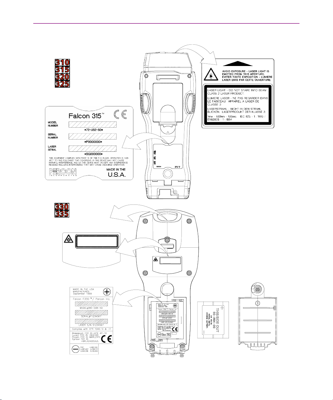
Product Labeling and Safety Information
AVOID EXPOSURE
LAS ER LIG HT IS EMM ITED
FROM THIS A PERT URE
LASER LIGHT - DO NOT S TARE INTO BEAM
CLASS 2 LASER PRODUCT.
1mw-680nm-10 0sec. IEC 825-1:199 3/
EN60825 - 1 : 1994
THIS EQUIPMENT COMPLIES WITH PA RT 15 OF THE FCC RULES.
OPERAT ION IS SUBJE CT TO THE FO LLOW ING TW O CO NDITIONS:
(1) THIS DEVICE MAY N OT CA USE HARMFUL INTERF ERENCE ,
AND (2) THIS DEVICE MUST A CCEPT A NY INT ERFERENCE
RECEIVED INC LUDING INTERFERE NCE THAT M AY CA USE
UNDES IRED O PERA TIO N.
AVOID EXPOSURE
LASER LIGHT IS EMMITED
FROM THIS APERTURE
LASER LIGHT - DO N OT S T ARE INTO BEA M
CLASS 2 LASER PRODUCT.
1mw-680nm-100sec. IEC 825-1:1993/
EN60825 - 1 : 1994
THIS EQUIPMENT COMPLIES WITH PART 15 OF THE FCC RULES.
OPERAT ION IS SUBJ E CT TO THE FOL LOW ING TWO CON DITIO NS :
(1) THIS DEVICE MAY NOT CA USE HARMFUL INTERFERENCE,
AND (2) THIS DEVICE MUST ACCEPT ANY INTERFERENCE
RECEIVE D IN CL UDING I NTE RFE RE NCE TH AT MA Y C A USE
UNDESIRED OPERATION.
Falcon DOS Portable Terminals User’s Guide < v >
Page 8

Advisory
Statement
CAUTION: Use of controls, adjustments, or performance of proce-
dures other than those specified herein may result in hazardous
visible or invisible laser light exposure.
FCC Information This device complies with Part 15 of the FCC Rules. Operation is sub-
ject to the following two conditions: (1) this device may not cause
harmful interference, and (2) this device must accept any interference received, including interference that may cause undesired
operation.
< vi > Falcon DOS Portable Terminals User’s Guide
Page 9

Contents
About This Book. . . . . . . . . . . . . . . . . . . . . . . . . . . . . . . . . . . . . . . . . . . . . . iii
Getting Help. . . . . . . . . . . . . . . . . . . . . . . . . . . . . . . . . . . . . . . . . . . . . . . . . iv
Product Labeling and Safety Information. . . . . . . . . . . . . . . . . . . . . . . . . . .v
Chapter One:
About Falcon DOS Terminals . . . . . . . . . . . . . . . . . . . . . . . . . . . . . . . . . . . . 1
Overview . . . . . . . . . . . . . . . . . . . . . . . . . . . . . . . . . . . . . . . . . . . . . . . . . . . . . . . . . . . . . . . . . . .2
Model Numbers. . . . . . . . . . . . . . . . . . . . . . . . . . . . . . . . . . . . . . . . . . . . . . . . . . . . . . . . . . . . . .2
Optional Accessories . . . . . . . . . . . . . . . . . . . . . . . . . . . . . . . . . . . . . . . . . . . . . . . . . . . . . . . . . .2
Falcon Dock. . . . . . . . . . . . . . . . . . . . . . . . . . . . . . . . . . . . . . . . . . . . . . . . . . . . . . . . . . . . . .2
Falcon 4-Slot Dock . . . . . . . . . . . . . . . . . . . . . . . . . . . . . . . . . . . . . . . . . . . . . . . . . . . . . . . .3
Portable Battery Charger. . . . . . . . . . . . . . . . . . . . . . . . . . . . . . . . . . . . . . . . . . . . . . . . . . . . 3
Care and Cleaning. . . . . . . . . . . . . . . . . . . . . . . . . . . . . . . . . . . . . . . . . . . . . . . . . . . . . . . . . . . .3
Chapter Two:
Using the Falcon . . . . . . . . . . . . . . . . . . . . . . . . . . . . . . . . . . . . . . . . . . . . . 5
Turning the Unit On and Off . . . . . . . . . . . . . . . . . . . . . . . . . . . . . . . . . . . . . . . . . . . . . . . . . . . . 6
First-Time Use . . . . . . . . . . . . . . . . . . . . . . . . . . . . . . . . . . . . . . . . . . . . . . . . . . . . . . . . . . . .6
“Please Wait” Messages . . . . . . . . . . . . . . . . . . . . . . . . . . . . . . . . . . . . . . . . . . . . . . . . . . . .6
Batteries . . . . . . . . . . . . . . . . . . . . . . . . . . . . . . . . . . . . . . . . . . . . . . . . . . . . . . . . . . . . . . . . . . .7
Low-Battery Warning . . . . . . . . . . . . . . . . . . . . . . . . . . . . . . . . . . . . . . . . . . . . . . . . . . . . . . 7
Replacing the Batteries . . . . . . . . . . . . . . . . . . . . . . . . . . . . . . . . . . . . . . . . . . . . . . . . . . . . .7
Auto-Shutoff. . . . . . . . . . . . . . . . . . . . . . . . . . . . . . . . . . . . . . . . . . . . . . . . . . . . . . . . . . . .10
The Keypad . . . . . . . . . . . . . . . . . . . . . . . . . . . . . . . . . . . . . . . . . . . . . . . . . . . . . . . . . . . . . . . .10
Input Modes . . . . . . . . . . . . . . . . . . . . . . . . . . . . . . . . . . . . . . . . . . . . . . . . . . . . . . . . . . . .14
Double Action Key Mode . . . . . . . . . . . . . . . . . . . . . . . . . . . . . . . . . . . . . . . . . . . . . . . . . .16
Cursors and Icons . . . . . . . . . . . . . . . . . . . . . . . . . . . . . . . . . . . . . . . . . . . . . . . . . . . . . . . .17
International Characters . . . . . . . . . . . . . . . . . . . . . . . . . . . . . . . . . . . . . . . . . . . . . . . . . . . 18
Falcon DOS Portable Terminals User’s Guide < vii >
Page 10

Contents
Repeating Keystrokes . . . . . . . . . . . . . . . . . . . . . . . . . . . . . . . . . . . . . . . . . . . . . . . . . . . . .20
The Viewport. . . . . . . . . . . . . . . . . . . . . . . . . . . . . . . . . . . . . . . . . . . . . . . . . . . . . . . . . . . . . . . 21
Moving the Viewport Display . . . . . . . . . . . . . . . . . . . . . . . . . . . . . . . . . . . . . . . . . . . . . . .21
Adjusting the Contrast . . . . . . . . . . . . . . . . . . . . . . . . . . . . . . . . . . . . . . . . . . . . . . . . . . . . 23
Using the Backlight . . . . . . . . . . . . . . . . . . . . . . . . . . . . . . . . . . . . . . . . . . . . . . . . . . . . . . .24
The Falcon Laser . . . . . . . . . . . . . . . . . . . . . . . . . . . . . . . . . . . . . . . . . . . . . . . . . . . . . . . . . . . .24
The Laser Triggers . . . . . . . . . . . . . . . . . . . . . . . . . . . . . . . . . . . . . . . . . . . . . . . . . . . . . . . .25
Changing the Laser Module’s Orientation. . . . . . . . . . . . . . . . . . . . . . . . . . . . . . . . . . . . . .25
Using the Long-Range Laser . . . . . . . . . . . . . . . . . . . . . . . . . . . . . . . . . . . . . . . . . . . . . . . .26
Attaching a Bar Code Reader. . . . . . . . . . . . . . . . . . . . . . . . . . . . . . . . . . . . . . . . . . . . . . . . . . .27
The Serial Port . . . . . . . . . . . . . . . . . . . . . . . . . . . . . . . . . . . . . . . . . . . . . . . . . . . . . . . . . . . . . .28
The Falcon Applications. . . . . . . . . . . . . . . . . . . . . . . . . . . . . . . . . . . . . . . . . . . . . . . . . . . . . . .29
Chapter Three:
The Falcon Dock. . . . . . . . . . . . . . . . . . . . . . . . . . . . . . . . . . . . . . . . . . . . . 31
About the Falcon Dock . . . . . . . . . . . . . . . . . . . . . . . . . . . . . . . . . . . . . . . . . . . . . . . . . . . . . . . 32
Attaching the Falcon Dock to the Computer . . . . . . . . . . . . . . . . . . . . . . . . . . . . . . . . . . . . . . .33
The Power Adapter . . . . . . . . . . . . . . . . . . . . . . . . . . . . . . . . . . . . . . . . . . . . . . . . . . . . . . . . . . 33
Using the Falcon Dock. . . . . . . . . . . . . . . . . . . . . . . . . . . . . . . . . . . . . . . . . . . . . . . . . . . . . . . .34
Maintenance . . . . . . . . . . . . . . . . . . . . . . . . . . . . . . . . . . . . . . . . . . . . . . . . . . . . . . . . . . . . . . . 35
Chapter Four:
The Falcon 4-Slot Dock. . . . . . . . . . . . . . . . . . . . . . . . . . . . . . . . . . . . . . . . 37
About the Falcon 4-Slot Dock . . . . . . . . . . . . . . . . . . . . . . . . . . . . . . . . . . . . . . . . . . . . . . . . . .38
Front Panel . . . . . . . . . . . . . . . . . . . . . . . . . . . . . . . . . . . . . . . . . . . . . . . . . . . . . . . . . . . . . 38
Back Panel. . . . . . . . . . . . . . . . . . . . . . . . . . . . . . . . . . . . . . . . . . . . . . . . . . . . . . . . . . . . . .39
Installation . . . . . . . . . . . . . . . . . . . . . . . . . . . . . . . . . . . . . . . . . . . . . . . . . . . . . . . . . . . . . . . . 40
Power Adapter . . . . . . . . . . . . . . . . . . . . . . . . . . . . . . . . . . . . . . . . . . . . . . . . . . . . . . . . . .40
Cables . . . . . . . . . . . . . . . . . . . . . . . . . . . . . . . . . . . . . . . . . . . . . . . . . . . . . . . . . . . . . . . . .40
Connecting the Dock to the Host . . . . . . . . . . . . . . . . . . . . . . . . . . . . . . . . . . . . . . . . . . . . 40
Creating a Dock Network . . . . . . . . . . . . . . . . . . . . . . . . . . . . . . . . . . . . . . . . . . . . . . . . . .41
Using the 4-Slot Dock . . . . . . . . . . . . . . . . . . . . . . . . . . . . . . . . . . . . . . . . . . . . . . . . . . . . . . . . 41
Charging a Falcon’s Batteries . . . . . . . . . . . . . . . . . . . . . . . . . . . . . . . . . . . . . . . . . . . . . . .41
Transferring Data . . . . . . . . . . . . . . . . . . . . . . . . . . . . . . . . . . . . . . . . . . . . . . . . . . . . . . . .41
< viii > Falcon DOS Portable Terminals User’s Guide
Page 11

Contents
Chapter Five:
Vehicle Mount Powered Dock . . . . . . . . . . . . . . . . . . . . . . . . . . . . . . . . . . 43
About the Vehicle Mount Powered Dock. . . . . . . . . . . . . . . . . . . . . . . . . . . . . . . . . . . . . . . . . .44
Using the Vehicle Mount Powered Dock . . . . . . . . . . . . . . . . . . . . . . . . . . . . . . . . . . . . . . . . . .45
Installation . . . . . . . . . . . . . . . . . . . . . . . . . . . . . . . . . . . . . . . . . . . . . . . . . . . . . . . . . . . . . . . . 46
Quick Start . . . . . . . . . . . . . . . . . . . . . . . . . . . . . . . . . . . . . . . . . . . . . . . . . . . . . . . . . . . . .46
Vehicle 12VDC Connection . . . . . . . . . . . . . . . . . . . . . . . . . . . . . . . . . . . . . . . . . . . . . . . . .46
Fuse Replacement . . . . . . . . . . . . . . . . . . . . . . . . . . . . . . . . . . . . . . . . . . . . . . . . . . . . . . . . 47
Falcon Vehicle Bracket. . . . . . . . . . . . . . . . . . . . . . . . . . . . . . . . . . . . . . . . . . . . . . . . . . . . .47
Custom Mounting Brackets. . . . . . . . . . . . . . . . . . . . . . . . . . . . . . . . . . . . . . . . . . . . . . . . .50
Chapter Six:
Troubleshooting Guide . . . . . . . . . . . . . . . . . . . . . . . . . . . . . . . . . . . . . . . 51
Serial Communications . . . . . . . . . . . . . . . . . . . . . . . . . . . . . . . . . . . . . . . . . . . . . . . . . . . . . . .52
Bar Codes . . . . . . . . . . . . . . . . . . . . . . . . . . . . . . . . . . . . . . . . . . . . . . . . . . . . . . . . . . . . . . . . .52
Batteries . . . . . . . . . . . . . . . . . . . . . . . . . . . . . . . . . . . . . . . . . . . . . . . . . . . . . . . . . . . . . . . . . .53
Index . . . . . . . . . . . . . . . . . . . . . . . . . . . . . . . . . . . . . . . . . . . . . . . . . . . . . 55
Falcon DOS Portable Terminals User’s Guide < ix >
Page 12

Page 13

>> Chapter One
About Falcon DOS Terminals
This chapter provides an overview of the Falcon line of DOS portable terminals. It
identifies the various model configurations and accessories and describes some of
the features of the Falcon models.
CHAPTER CONTENTS
Overview <2>
Model Numbers <2>
Optional Accessories <2>
Falcon Dock
Falcon 4-Slot Dock
Portable Battery Charger
Care and Cleaning <3>
< 1 >
Page 14
About Falcon DOS Terminals
>> Overview
Falcon DOS portable data terminals are handheld computers
designed for data collection. The Falcon DOS portable line includes
8-line and 16-line models.
Some Falcons have integrated laser scanners, making them highperformance bar code readers as well. Models without integrated
lasers accept input from most industry-standard bar code readers.
Both the 8-line and the 16-line Falcon models are available in batch
and wireless (radio frequency, or RF) configurations. Wireless models provide instant communication of data between the unit and a
host computer.
>> Model Numbers
Ta bl e 1-1 lists the model numbers of the Falcon DOS portables and
describes their configurations.
Table 1-1: Falcon Models
Model Number 8-Line 16-Line Batch RF
310 X X
315 X X
320 X X
325 X X
330 X X
335 X X
>> Optional Accessories
Falcon Dock The Falcon Dock is the docking station for the Falcon. It’s two pri-
mary uses are:
G Recharging the Falcon’s NiCD or NiMH battery pack.
G Providing a connection for serial communications between
the Falcon and the host computer.
Review chapter 3
for more information about the Falcon Dock.
< 2 > Falcon DOS Portable Terminals User’s Guide
Page 15
Care and Cleaning
The Dock for the Falcon and uses a dual IR/hardwire interface to provide nearly transparent full duplex serial communications between the Falcon and and the host computer.
For additional information, on communication limitations, review
the Falcon DOS Portable Terminals Advanced User’s Guide.
Falcon 4-Slot Dock The Falcon 4-Slot Dock provides battery recharging and serial com-
munications for up to four Falcon portables at a time.
Review chapter 4
Dock.
NOTE: There is no 4-slot dock for the Falcon and .
for more information about the Falcon 4-Slot
Portable Battery
Charger
When not using a Falcon Dock or a Falcon 4-Slot Dock, the optional
portable battery charger can be used to recharge the Falcon’s batteries. Rechargeable batteries that have lost all power can be fully
recharged in about 2 hours.
NOTE: To purchase accessories, or for additional information, contact a Percon representative, or visit the Percon Web site at
www.percon.com
>> Care and Cleaning
With normal use, the Falcon DOS portable terminal requires no
maintenance. If it gets dirty, wipe it with a damp cloth.
G Do not immerse the Falcon in liquid.
G Do not use any abrasive cleaners on the display screen.
.
Falcon DOS Portable Terminals User’s Guide < 3 >
Page 16

Page 17

>> Chapter Two
Using the Falcon
The Falcon is an enhanced DOS computer that provides the user unique functionality
and flexibility. The Falcon unit can contain one or more specialized applications that
collects bar code data or other information. This chapter will demonstrate how easy
it is to use the Falcon.
Finding Out More: For more information (including instructions on transferring
files to and from a Falcon), see the Falcon DOS Portable Terminals Advanced User’s
Guide.
CHAPTER CONTENTS
Turning the Unit On and Off <6>
First-Time Use
“Please Wait” Messages
Batteries <7>
Low-Battery Warning
Replacing the Batteries
Auto-Shutoff
The Keypad <10>
Input Modes
Double Action Key Mode
Cursors and Icons
International Characters
Repeating Keystrokes
The Viewport <21>
Moving the Viewport Display
Adjusting the Contrast
Using the Backlight
The Falcon Laser <24>
The Laser Triggers
Changing the Laser Module’s Orientation
Using the Long-Range Laser
Attaching a Bar Code Reader <27>
The Serial Port <28>
The Falcon Applications <29>
< 5 >
Page 18
Using the Falcon
>> Turning the Unit On and Off
Press the Power
Power key to turn the unit on or off.
PowerPower
G The Power key for the Falcon 31x-32x is located at the top
left of the keypad matrix.
G The Power key for the Falcon 33x is located at the bottom
left of the keypad matrix.
First-Time Use The first time the Falcon unit is turned on, the following message
may be seen:
Initial power-up or
critical data loss.
Drive D formatted.
Press any key...
This message appears with normal operation and does not indicate
“Please Wait”
Messages
a problem. Press the ENTER
boot up.
NOTE: This message will also appear when new or recharged batteries are placed in the unit after the backup battery has been
drained.
Depending upon the type of PC card installed, the Falcon will perform the various operations placed on the card.
G During these operations, the unit will display a message in
reverse video indicating that it is powering on or off.
ENTER key, and the Falcon will continue to
ENTERENTER
G When turning the unit on, wait until the message disap-
pears before using the unit.
G When turning the unit off, to replace the batteries, wait
until the message disappears before removing the batteries.
< 6 > Falcon DOS Portable Terminals User’s Guide
Page 19
>> Batteries
Batteries
Falcon batteries are available in rechargeable, easy-to-replace nickel
cadmium (NiCD) or nickel metal-hydride (NiMH) battery packs.
G The Falcon and can use three standard AA alka-
line batteries, NiCD, or NiMH battery packs.
G For models and , only NiMH battery packs are
recommended.
G For the Falcon and , NiMH battery packs are rec-
ommended. Individual alkaline batteries are not compatible
with these models.
The Falcon also has a built-in lithium backup battery that temporarily saves data when the replaceable batteries lose their charge.
NOTE: A battery icon, shown at the left, is displayed at the top right
corner of the viewport when the Falcon , , ,and
are running with a charged battery.
Low-Battery
Warning
Replacing the
Batteries
When the batteries have lost most of their charge, an icon of an
“empty” battery appears at the top right corner of the Falcon
screen. (See the icons at left.)
G The Falcon also can be programmed to emit a beep at inter-
vals when the battery is low.
G The backup battery will protect all data in memory while the
other batteries are out of the unit.
After recharging or replacing the batteries and turning the Falcon
back on, the unit will return to the application operating when it
was turned off.
When the empty-battery icon appears or the warning beep is heard,
turn off the Falcon and recharge or replace the batteries as soon as
possible. Tur n t he Fa l c o n off before changing the batteries. Removing batteries while the unit is on can trigger a number of problems,
including loss of stored data.
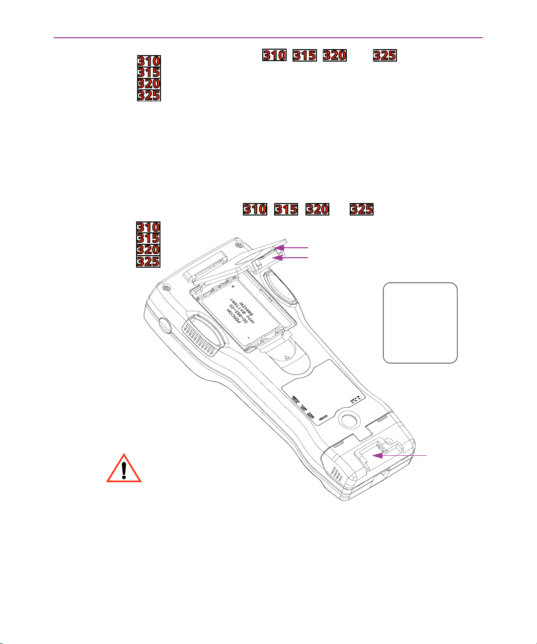
The Falcon’s batteries (except for the lithium backup battery) are located in a compartment on the back of the unit (see figure 2-1
replace the batteries, complete the following steps:
). To
Falcon DOS Portable Terminals User’s Guide < 7 >
Page 20
Using the Falcon
For Falcon models , , , and :
1. Turn the Falcon off.
2. Detach the elastic hand strap on the back of the Falcon by pull-
ing its hook out of the holder near the base.
3. The battery-compartment cover has a tab located in the middle
of the unit. Firmly press the tab up until the cover is released
from the body of the unit. (A symbol on the body indicates the
direction in which to press the tab.)
4. Pull the end of the exposed plastic ribbon in the battery com-
partment until the batteries pop out.
Figure 2-1: NiCD Battery Pack in Falcon , , , or Battery Compartment
Battery-compartment cover
Tab
NICD Battery Pack
Label
+
Be sure to turn the Falcon off
before removing the batteries. All data in memory may
be lost if the unit is not off
when batteries are removed.
5. Lay the plastic ribbon along the bottom of the battery compart-
ment with the end sticking out.
6. Alkaline Batteries Insert the batteries in the positions indi-
cated by the diagram inside the compartment.
< 8 > Falcon DOS Portable Terminals User’s Guide
PERCON
00-862-00
-
E9642W
NiCD BATTERY
Strap-hook
holder
Page 21
NiCD or NiMH Battery Pack Find the positive (+) and nega-
tive (-) symbols on the battery pack’s label (see figure 2-1
the label side out, tilt the positive end of the pack into the upper end of the battery compartment, and then firmly press the
negative end until it is fully inserted into the battery
compartment.
7. Replace the battery-compartment cover by sliding it into place.
(Be sure the plastic ribbon is tucked underneath the cover.)
8. Replace the hand-strap hook in its holder.
NOTE: The Falcon will not function unless the battery-compartment
cover is in place and securely latched.
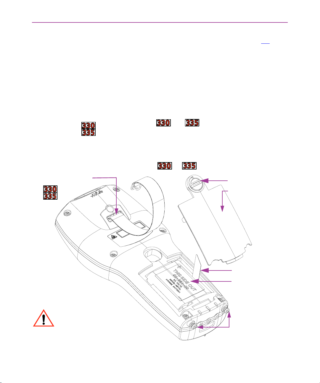
For Falcon models and :
1. Turn the Falcon off.
2. Detach the elastic hand strap on the back of the Falcon by
releasing its hook from the connection at the base of the unit.
Figure 2-2: NiMH Battery Pack in the Falcon or Battery Compartment
Upper Hand Strap
connection
dial
Battery-compartment
cover
Batteries
). With
Be sure to turn the Falcon off
before removing the batteries. All data in memory may
be lost if the unit is not off
when batteries are removed.
Plastic Ribbon
NiMH Battery Pack
Lower Hand Strap
connections
Falcon DOS Portable Terminals User’s Guide < 9 >
Page 22

Using the Falcon
3. Turn the dial counter-clockwise to release the battery compart-
ment cover.
4. Pull the end of the exposed plastic ribbon in the battery com-
partment until the batteries pop out.
5. Lay the plastic ribbon along the bottom of the battery compart-
ment with the end sticking out.
6. NiMH Battery Pack Find the positive (+) and negative (-) sym-
bols on the battery pack’s label (see figure 2-2
side out, tilt the positive end of the pack into the upper end of
the battery compartment, and then firmly press the negative
end until it is fully inserted into the battery compartment.
7. Replace the battery-compartment cover by inserting the bottom
tab into the slot and rotating the cover latch in a clockwise
direction. (Be sure the plastic ribbon is tucked underneath the
cover.)
8. Replace the hand-strap hook in the clip.
NOTE: The battery pack should not be replaced in a dirty or harsh
environment. When the battery compartment cover is off, any dust
or moisture that enters the battery compartment can get into the
main unit, potentially causing damage. The Falcon will not function
unless the battery-compartment cover is in place and securely
latched.
). With the label
Auto-Shutoff The Falcon has an automatic-shutoff feature that helps conserve
battery life while not in use.
G When a specified amount of time has passed since a key or
a trigger has been pressed, the Falcon turns itself off.
G All data in memory is maintained.
G Press the power button to turn the unit back on.
>> The Keypad
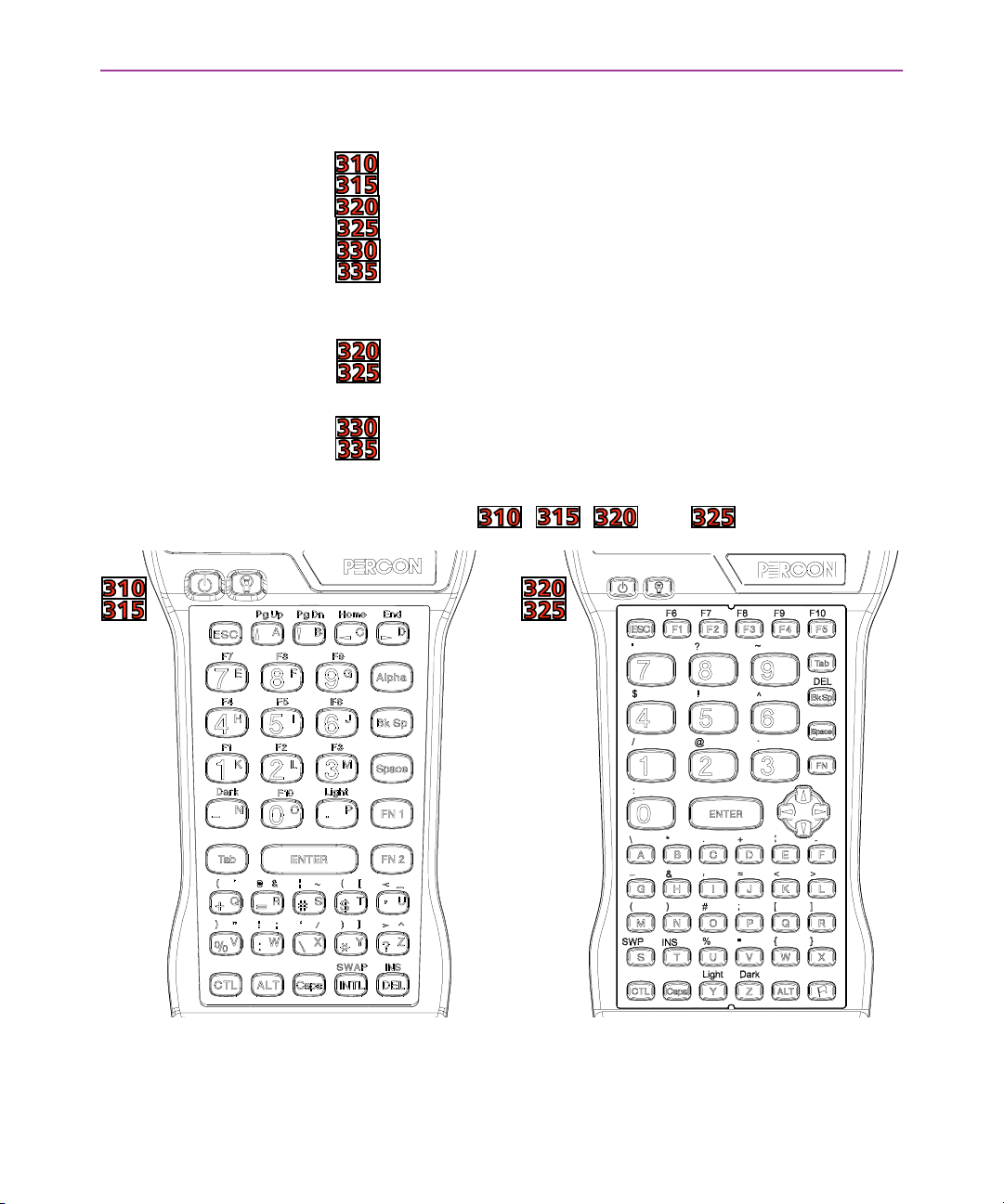
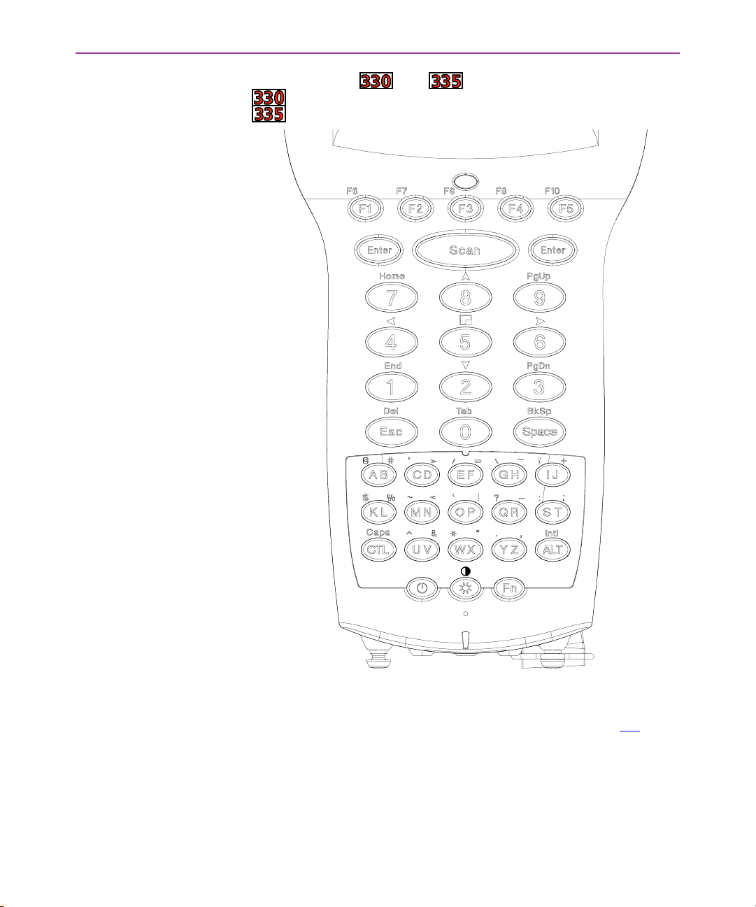
Used individually or in combination, the keys of the Falcon keypad
provide equivalents to almost all the keys found on a standard keyboard. The keypads are shown in figures 2-3
G Falcon models and have 41 keys.
G Falcon models and have 57 keys.
G Falcon models and have 38 keys.
< 10 > Falcon DOS Portable Terminals User’s Guide
and 2-4.
Page 23
The Keypad
The following keys appear on a standard IBM compatible computer
keyboard but are not used on the Falcon:
GF11
F11 GCaps Lock
F11F11
GF12
F12 GScroll Lock
F12F12
GLeft Shift
GRight Shift
GRight Alt
GRight Ctrl
G
GPg Up
GG
G
GPg Down
GG
GRight bracket [[[[ GLeft bracket ]]]]
Shift* GPause/Break
ShiftShift
Shift* GPrint Screen/SysReq
ShiftShift
Alt GNum Lock
AltAlt
Ctrl GNumeric keypad keys
CtrlCtrl
Pg Up G
Pg UpPg Up
Pg Down G
Pg DownPg Down
Caps Lock*
Caps LockCaps Lock
Scroll Lock
Scroll LockScroll Lock
Pause/Break
Pause/BreakPause/Break
Print Screen/SysReq
Print Screen/SysReqPrint Screen/SysReq
Num Lock
Num LockNum Lock
GHome
Home
GG
HomeHome
GEnd
End
GG
EndEnd
*The Falcon’s Caps
Figure 2-3: The Keypad for Falcon models , , , and .
Caps key provides the functions of these keys.
CapsCaps
Falcon DOS Portable Terminals User’s Guide < 11 >
Page 24
Using the Falcon
Figure 2-4: The Keypad for Falcon models and .
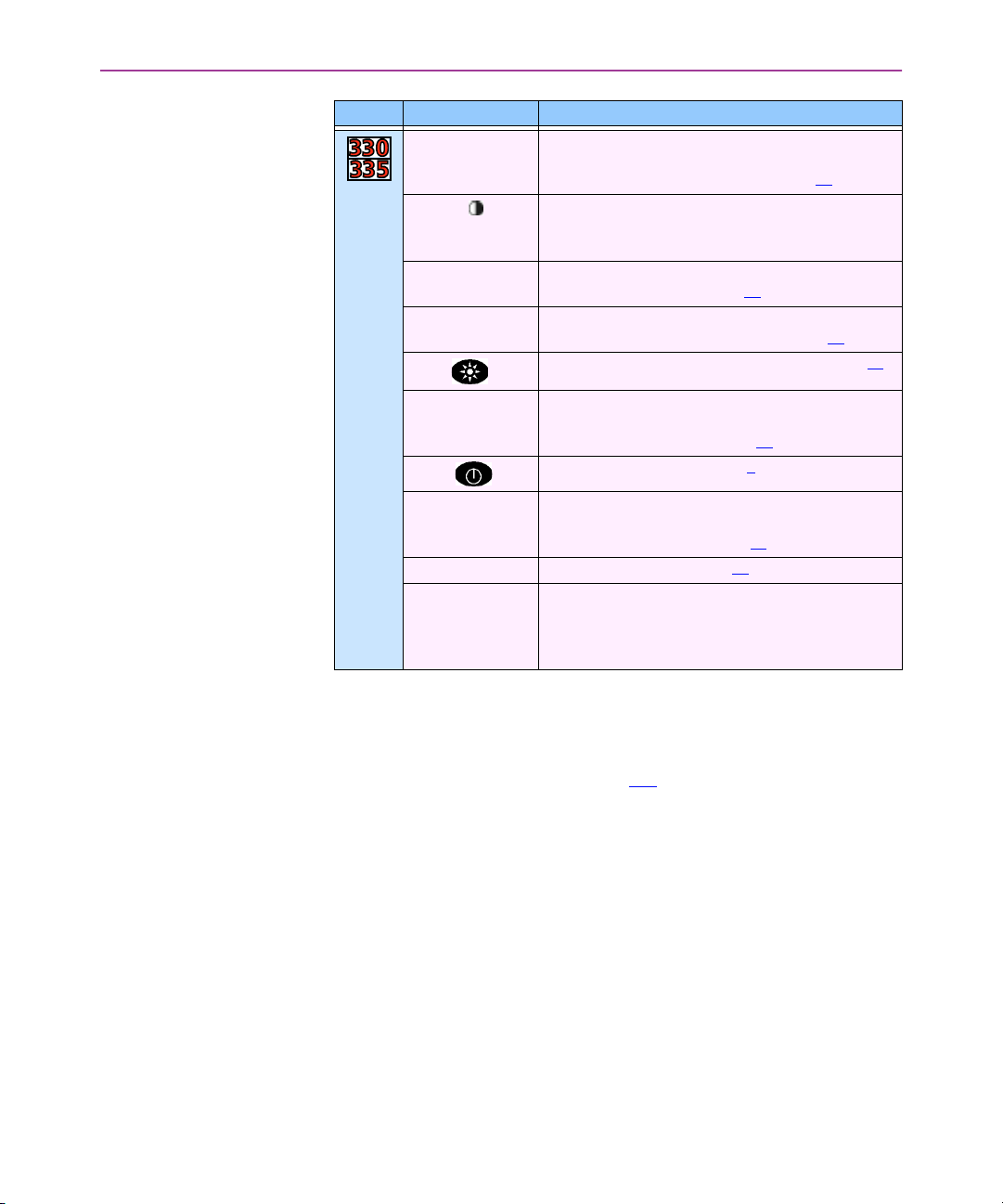
The Falcon has a few keys that are not found on a standard IBM
compatible PC keyboard. These keys are shown in table 2-1. Page
numbers indicate where to find more information about the keys.
< 12 > Falcon DOS Portable Terminals User’s Guide
Page 25
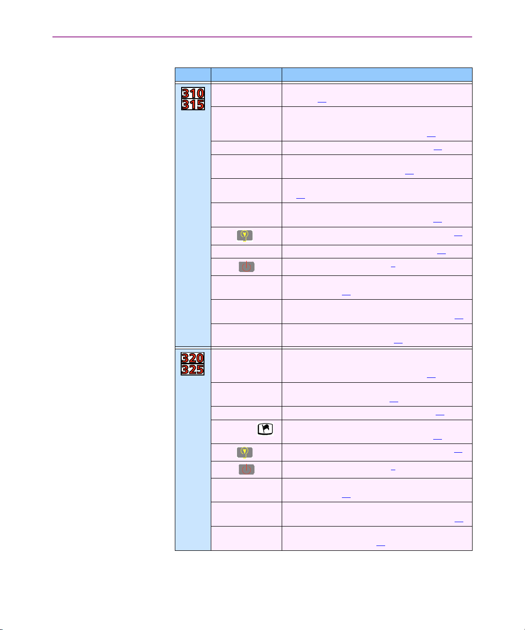
Table 2-1: Falcon Keys Not Found on a Standard Keyboard
Models Key Default Use
Alpha
Alpha Toggles the Falcon between Alpha mode and Normal
AlphaAlpha
mode (p. 14)
Caps
Caps When pressed and released, toggles Caps mode on
CapsCaps
and off; when held down, acts equivalently to the Shift
key on a standard computer keyboard (p. 14
Dark
Dark Darkens the background of the viewport (p.23)
DarkDark
FN 1
FN 1 Outputs the blue symbol or activates the function (F1
FN 1FN 1
F10
F10) above the next key pressed (p. 14
F10F10
FN 2
FN 2 Outputs the black symbol above the next key pressed
FN 2FN 2
(p. 14)
IIIINTL
NTL Outputs an international character generated by the
NTLNTL
combination of the next two keypresses (p. 18
Lamp ( )
Lamp ( )
Lamp ( )Lamp ( )
Light
Light Lightens the background of the viewport (p. 23)
Light Light
Power ( )
Power ( )
Power ( )Power ( )
Swap
Swap Switches the assigned actions of the right and left
SwapSwap
Left laser trigger Operates the Falcon laser or an attached bar code
Right laser trigger Same as the Alpha
Caps
Caps When pressed and released, toggles Caps mode on
CapsCaps
FN
FN Outputs the symbol or activates the function (F6
FNFN
Dark
Dark Darkens the background of the viewport (p. 23)
DarkDark
International
International ()
InternationalInternational
Lamp ( )
Lamp ( )
Lamp ( )Lamp ( )
Power ( )
Power ( )
Power ( )Power ( )
SWP
SWP (Swap) Switches the assigned actions of the right and left
SWPSWP
Left laser trigger
Left laser trigger Operates the Falcon laser or an attached bar code
Left laser triggerLeft laser trigger
Right laser trigger
Right laser trigger Same as the FN
Right laser triggerRight laser trigger
()
() ()
Turns the backlight on and off in the viewport (p. 24)
Turns the Falcon on and off (p. 6)
laser triggers (p. 25)
reader; can be reprogrammed as a keypad key (p. 25
laser trigger or a keypad key (p. 25
and off; when held down, acts equivalently to the Shift
key on a standard computer keyboard (p. 14
above the next key pressed (p. 14)
Outputs an international character generated by the
combination of the next two keypresses (p. 18
Turns the backlight on and off in the viewport (p. 24)
Turns the Falcon on and off (p. 6)
laser triggers (p. 25
reader; can be reprogrammed as a keypad key (p. 25
trigger or a keypad key (p. 25
The Keypad
Shift
ShiftShift
)
F1–
F1F1
)
)
Alpha key; can be reprogrammed as a
AlphaAlpha
)*
Shift
ShiftShift
)
F6–F10
F10)
F6F6
F10F10
)
)
FN key; can be reprogrammed as a laser
FNFN
)*
)*
)*
Table continues
Falcon DOS Portable Terminals User’s Guide < 13 >
Page 26
Using the Falcon
Models Key Default Use
Caps
Caps When pressed and released, toggles Caps mode on
CapsCaps
and off; when held down, acts equivalently to the Shift
key on a standard computer keyboard (p. 14
Contrast ( )
Contrast ( )
Contrast ( )Contrast ( )
FN
FN Outputs the symbol or activates the function (F6
FNFN
IIIINTL
NTL Outputs an international character generated by the
NTLNTL
Lamp ( )
Lamp ( )
Lamp ( )Lamp ( )
Left
Left Enter
Enter key Operates as the standard Enter
LeftLeft
EnterEnter
Power ( )
Power ( )
Power ( )Power ( )
Right
Right Enter
Enter key Operates as the standard Enter
RightRight
EnterEnter
Scan
Scan Operates the Falcon laser (p. 25)*
ScanScan
Viewport Panning
Mode
*For information about reprogramming triggers, left, and right enter keys as keypad
keys, see the Falcon DOS Portable Data Terminals Advanced User’s Guide.
Activated by pressing Fn-Lamp
will decrease contrast; right
increase contrast of the display.
above the next key pressed (p. 14
combination of the next two keypresses (p. 18
Turns the backlight on and off in the viewport (p. 24)
Left
Left or Right Enter
Right Enter key can be reprogrammed to be one
LeftLeft
Right EnterRight Enter
of a set of other keypad keys (p. 25)*
Turns the Falcon on and off (p. 6)
Left
Left or Right Enter
Right Enter key can be reprogrammed to be one
LeftLeft
Right EnterRight Enter
of a set of other keypad key (p. 25)*
Fn-5
Fn-5 toggles the viewport panning mode on or off; the
Fn-5Fn-5
arrow keys can be used to effect panning (keys 2222,4444,6666,
and 8888); use the panning toggle key (key 5555) to exit paning mode and return the screen to cursor mode.
Fn-Lamp; left
Fn-LampFn-Lamp
left and down arrow
leftleft
right and up arrow
rightright
up arrow keys will
up arrowup arrow
)
Enter or Return
Return key; either the
EnterEnter
ReturnReturn
Enter or Return
Return key; either the
EnterEnter
ReturnReturn
down arrow keys
down arrowdown arrow
)
F6–F10
F6F6
)
Shift
ShiftShift
F10)
F10F10
Input Modes The current input mode determines key functions on the Falcon. The
input modes are described in table 2-2
< 14 > Falcon DOS Portable Terminals User’s Guide
.
Page 27
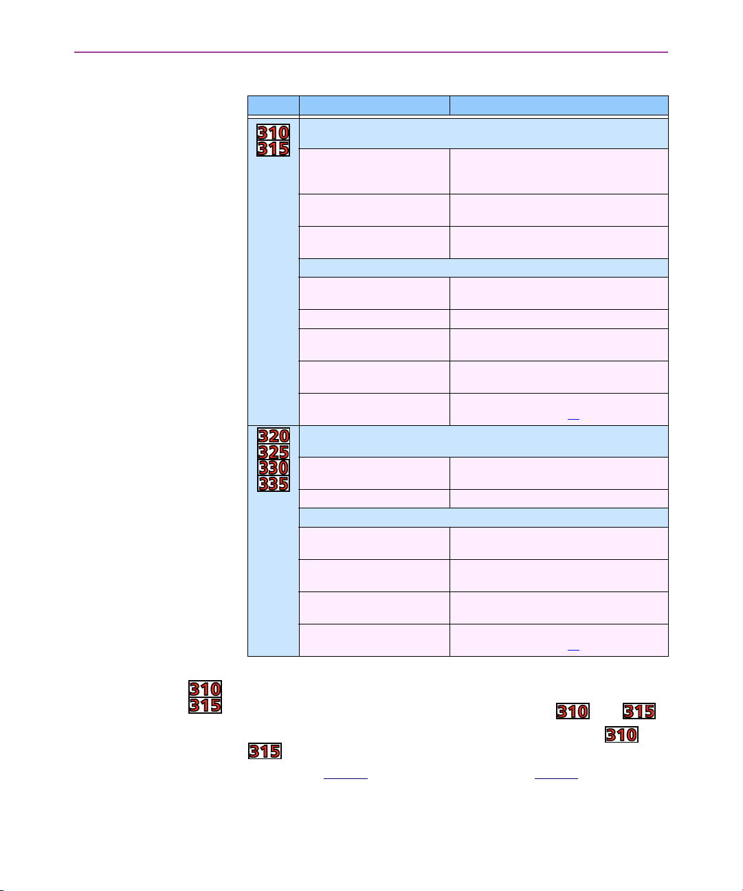
Table 2-2: Keypad Input Modes
Models Input Mode Result of Keypress
The Keypad
Type 1—Remains in effect after each keypress until discontinued by
user
Normal Outputs the white number or symbol on
Alpha Outputs the yellow letter on the key (lower-
Caps (used with Alpha mode) Outputs the uppercase yellow letter on the
Type 2—Affects only a single keypress or combination of keypresses
Function 1 Outputs the blue symbol or function above
Function 2 Outputs the black symbol above the key
Control Outputs the control meaning for alphanu-
Alternate Outputs the alternate meaning for alphanu-
International Outputs a character from the international
Type 1—Remains in effect after each keypress until discontinued by
user
Normal Outputs the letter (lowercase), number, or
Caps Outputs the uppercase letter on the key
Type 2—Affects only a single keypress or combination of keypresses
Function (Fn
Control (Ctrl
Alternate (Alt
International (Intl
Fn)* Outputs the symbol or function above the
FnFn
Ctrl) Outputs the control meaning for alphanu-
CtrlCtrl
Alt) Outputs the alternate meaning for alphanu-
AltAlt
Intl) Outputs a character from the international
IntlIntl
the key, or performs an action (e.g., moves
left)
case unless used with Caps mode)
key
the key
meric or function keys
meric or function keys
character set (see page 18
function on the key
key
meric or function keys
meric or function keys
character set (see page 18
)
)
Working with Input Modes
NOTE: This section applies only to Falcon models and .
The color coding of the keys and characters on models and
reflects input mode functions.
G The yellow
Alpha
Alpha key works with the yellow letters on the
AlphaAlpha
other keys.
Falcon DOS Portable Terminals User’s Guide < 15 >
Page 28
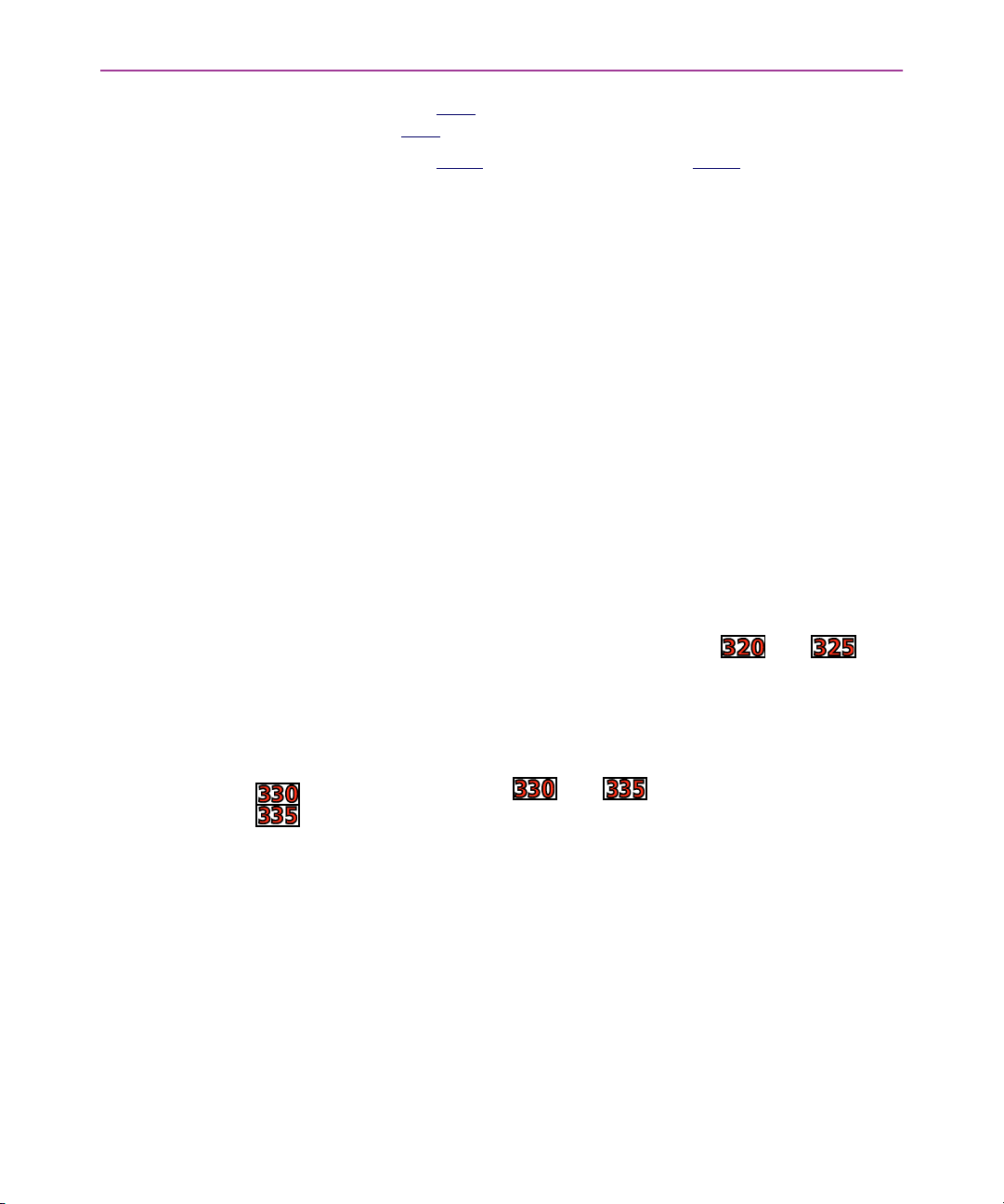
Using the Falcon
G The blue
blue
characters printed above some of the keys.
FN 1
FN 1 key works with the functions (F1
FN 1FN 1
F1–F10
F10) and the
F1F1
F10F10
G The black
ations printed above some of the keys.
For most applications, the letters and numbers are all that are
needed.
G Input letters by pressing the Alpha
mode) and pressing the keys for the letters.
G Press the Caps
G Press the Alpha
G In normal mode, numbers and punctuation characters can
be selected by pressing the appropriate key.
A type-1 mode can be temporarily overridden without actually
changing the mode. For example, when entering numbers in Normal mode, to type a letter:
G Hold down the Alpha
letter.
G Release the Alpha
G Use the Caps
without changing to Caps mode.
NOTE: Because they have more keys, models and have
fewer possible outputs from a single key and are easier for a beginner to use.
FN 2
FN 2 key works with the black characters or oper-
FN 2FN 2
Alpha key (to turn on Alpha
AlphaAlpha
Caps key with the Alpha
CapsCaps
Alpha key again to return to the normal mode.
AlphaAlpha
Alpha key while pressing the key for that
AlphaAlpha
Alpha key; the Falcon will still be in Normal mode.
AlphaAlpha
Caps key the same way to enter an uppercase letter
CapsCaps
Alpha key for uppercase letters.
AlphaAlpha
Double Action Key
Mode
< 16 > Falcon DOS Portable Terminals User’s Guide
There are two additional modes of operation, which affect how alpha keys and the punctuation characters above the alpha keys are
accessed. The Falcon and have only 38 keys.
G Thirteen of these keys are used for alpha keys (the letters A-
Z).
G Each key has two letters on the key itself, and two punctua-
tion characters above the key.
G Accessing the alpha character printed on the left side of the
key (the “first” letter) is done as normal.
G Accessing the alpha character printed on the right side of
the key (the “second” letter) depends upon the mode of
operation.
Page 29

Selecting Alpha Characters in Double Strike Mode
The Keypad
G Left character: Press the Alpha
predetermined time-out (the default is 330ms), the character will be displayed.
G Right character: Quickly press the Alpha
ond key press must occur before the predetermined timeout (the default is 330ms).
This mode is called the double strike mode, because it requires two
rapid presses on a key to access the second (the right-most) character.
Selecting Alpha Characters in Press and Wait Mode
G Left character: Press an Alpha
G Right character: Press the Alpha
mined time-out (the default is 330ms).
This mode is called press and wait mode, because it requires pressing the key and holding it down for a certain amount of time to access the second (right-most) character.
The mode and time-out (for either mode) can be changed via the
Falcon configuration driver, the Run-Time Library or by bar code
scanning.
The second character can be accessed in this way regardless of other
types of input modes the Falcon and is in. This includes
Fn
Fn, Ctrl
Ctrl, and Alt
FnFn
CtrlCtrl
BBBB character:
G Press the Fn
G Perform the action to select the second (right-most) charac-
The exception to the above rule is during International key entry. See
the section on International key entry for more details.
Alt key entries. To get the punctuation symbol above the
Alt Alt
Fn key
FnFn
ter for the key the BBBB is on (this depends upon the Double
Action
Action key mode of operation).
ActionAction
Alpha key once and release. After a
AlphaAlpha
Alpha key twice. The sec-
AlphaAlpha
Alpha key once and release
AlphaAlpha
Alpha key and hold for a predeter-
AlphaAlpha
Double
DoubleDouble
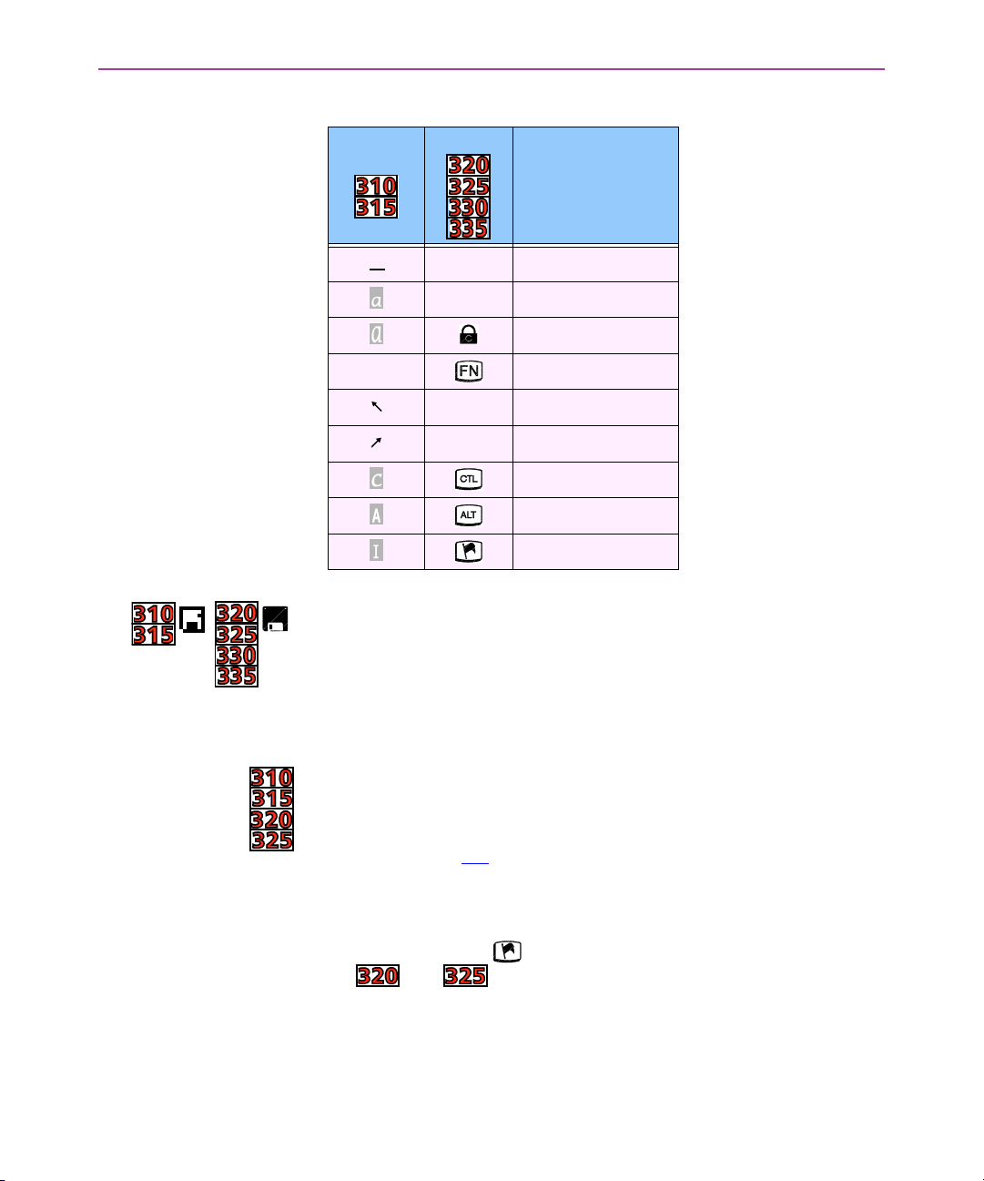
Cursors and Icons
The shape of the Falcon’s cursor in the viewport is a key to the current input mode. Table 2-3
the corresponding cursors.
Icons located along the right side of the viewport indicate the current input mode. Table 2-3
the corresponding icons.
Falcon DOS Portable Terminals User’s Guide < 17 >
identifies the various input modes and
identifies the various input modes and
Page 30
Using the Falcon
Table 2-3: Cursors, Icons, and Input Modes
Icon
Cursor
None Normal
N/A Function
Input Mode
N/A Alpha
Caps
N/A Function 1
N/A Function 2
Control
Alternate
International
During operations that require use of a disk drive, a disk icon appears on the right side of the viewport. This indicates that the unit is
busy. Wait until the icon disappears before continuing to use the
unit. The icons are shown at the left.
International
Characters
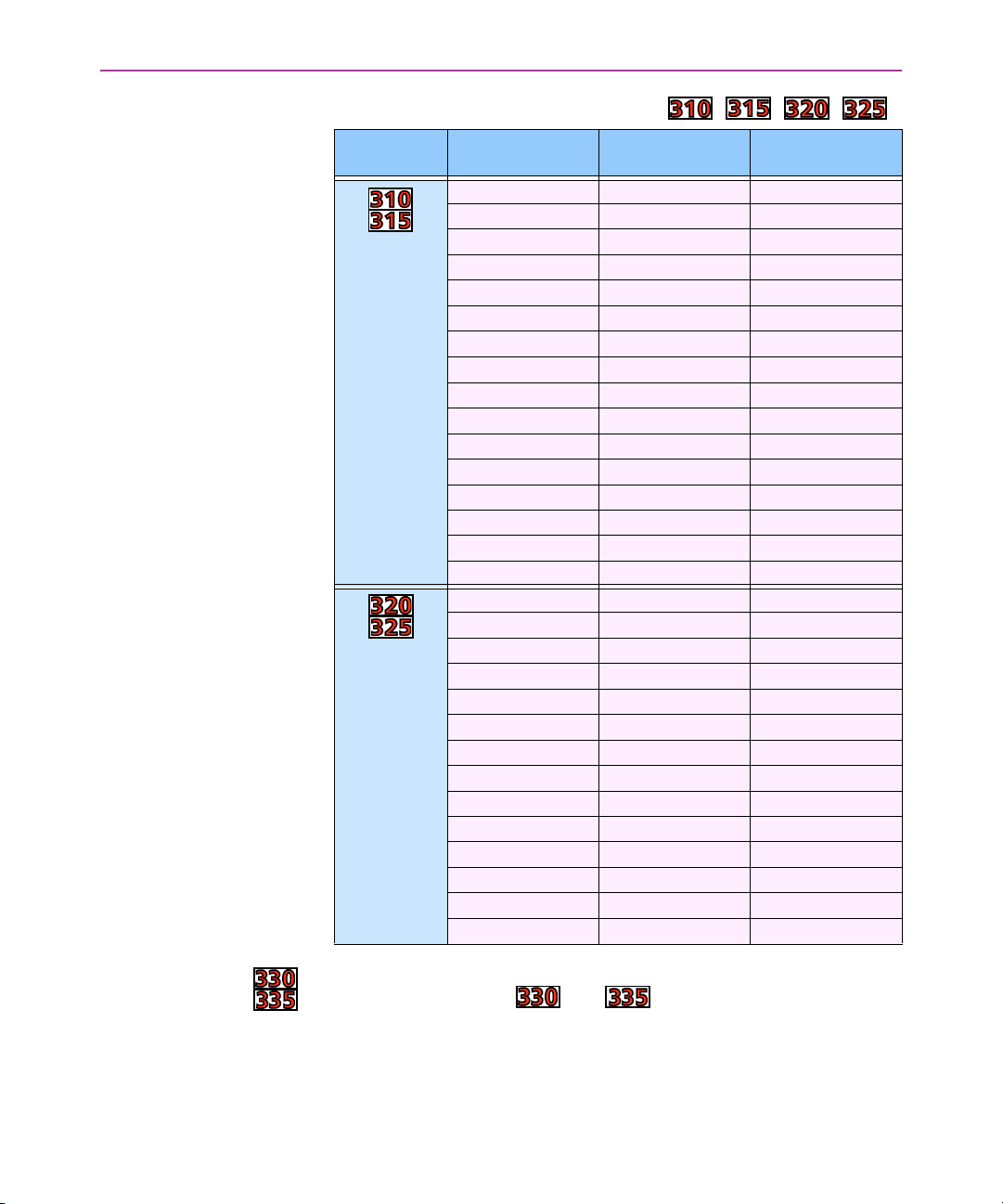
The international character set contains letters and symbols commonly used in Western European languages. Enter international
characters by using the following key sequence:
Intl
Intl accent letter
IntlIntl
G The accent is a character from the “Accent or Letter” column
of table 2-4
G The letter is a character from the “Letter” column in the
same row.
NOTE: The Intl
Intl key ( ) is orange with a white flag in Falcon mod-
IntlIntl
els and .
< 18 > Falcon DOS Portable Terminals User’s Guide
Page 31
The Keypad
Table 2-4: International Character Key Combinations for Falcon , , , .
Models
International
Characters
á, é, í, ó, ú, É ‘ (apostrophe) a, e, i, o, u, E
à, è, ì, ò, ù ` a, e, i, o, u
â, ê, î, ô, û ^ a, e, i, o, u
ä, ë, ï, ö, ü, ÿ, Ä, Ö, Ü : a, e, i, o, u, y, A, O, U
å, Å @ a, A
ç or Ç None c or C
ñ or Ñ None n or N
ñ or Ñ ~ n or N
ß s s
æ a e
Æ A E
¿ ? ?
¡ ! !
£ FN 1
¥ FN 2
ç or Ç , (comma) c or C
á, é, í, ó, ú, É ‘ (apostrophe) a, e, i, o, u, E
ç or Ç ‘ (apostrophe) c or C
à, è, ì, ò, ù ` a, e, i, o, u
â, ê, î, ô, û ^ a, e, i, o, u
ä, ë, ï, ö, ü, ÿ, Ä, Ö, Ü : a, e, i, o, u, y, A, O, U
å, Å @ None
ç or Ç None c or C
ñ or Ñ None n or N
ñ or Ñ ~ None
ß s None
¿ ? None
¡ ! !
¢, £, ¥ $ c, l, y
æ or Æ ! e or E
Accent or Letter Letter
FN 1 + $ None
FN 1FN 1
FN 2 + $ None
FN 2FN 2
To lessen the number of keystrokes required to enter an International key, the Falcon and keypad is designed according
to the following guidelines:
G The Intl
Intl key is a combination of keystrokes (Fn-Alt
IntlIntl
Fn-Alt).
Fn-AltFn-Alt
Falcon DOS Portable Terminals User’s Guide < 19 >
Page 32
Using the Falcon
G All accent characters are the first (left-most) character on a
key. The Double Action
Double Action key method is never used to access an
Double ActionDouble Action
accent characters.
G The format for entering an International key sequence
remains the same.
The following table describes the key sequences for all International
characters for the Falcon and :
Table 2-5: International Character Key Combinations for the Falcon and .
Repeating
Keystrokes
Models
International
Characters
á, é, í, ó, ú, É ‘ (apostrophe) a, e, i, o, u, E
ç or Ç ‘ (apostrophe) c or C
à, è, ì, ò, ù ` a, e, i, o, u
â, ê, î, ô, û ^ a, e, i, o, u
ä, ë, ï, ö, ü, ÿ, Ä, Ö, Ü : a, e, i, o, u, y, A, O, U
ß s s
å, Å @ None
ñ or Ñ ~ m, n, M, or N
¿ ? None
¡ ! !
¢, £, ¥ $ c, k, l, y
æ or Æ ! e or E
Accent or Letter Letter
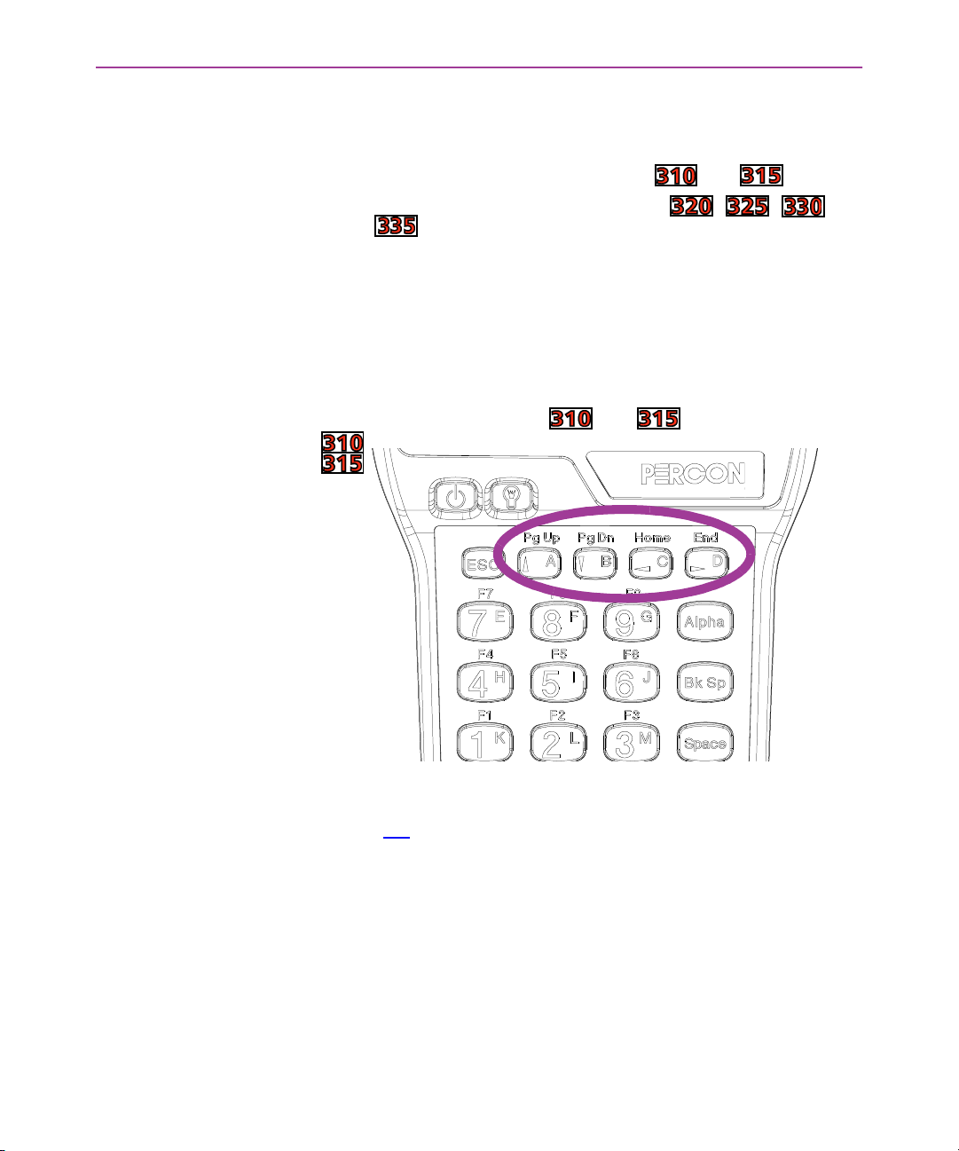
The keypad for the Falcon models and (only) features
support for repeating keystrokes:
G Press and hold the key to repeat a keystroke.
G After a brief pause, the keystroke will be automatically
repeated until the key is released.
This feature can be particularly useful with such keys as Bk
Bk Sp
Sp and
BkBk
SpSp
the cursor keys.
< 20 > Falcon DOS Portable Terminals User’s Guide
Page 33
>> The Viewport
The Falcon’s viewport is a backlit liquid crystal display of:
When entering more than the maximum number of characters, the
text in the viewport will scroll to the left to display the additional
characters in the line.
The Viewport
G 21 characters in 8 rows on models and
G 20 characters in 16 rows on models , , and
.
Moving the
Viewport Display
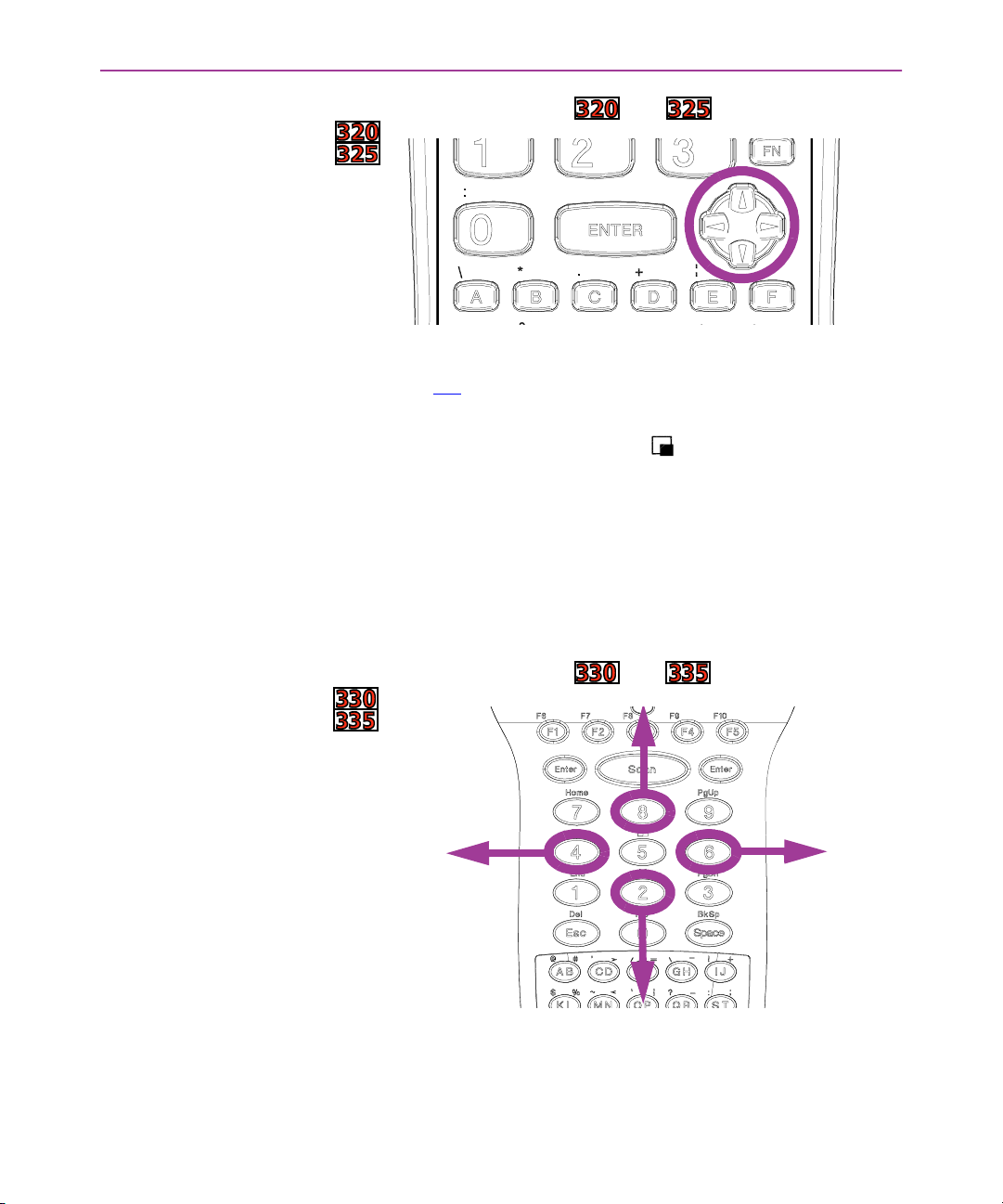
Figure 2-5: Location of the Cursor Keys in the Falcon and
The viewport display can be moved to the left or right by half
screens to view long lines of text.
G Press and hold the FN
2-5
) to move the display up, down, to the left, or to the
right.
FN 1111 key. Use the cursor keys (see figure
FNFN
G Release the FN
ible.
It is also possible to press and release the FN
the viewport several times in one or more directions. When finished,
press and release the FN
position.
Falcon DOS Portable Terminals User’s Guide < 21 >
FN 1111 key to make the current cursor position vis-
FNFN
FN 1111 key and then move
FNFN
FN 1111 key again to return to the current cursor
FNFN
Page 34
Using the Falcon
Figure 2-6: Location of the Cursor Keys in the Falcon and
G Press and hold the FN
ure 2-6
right.
G The viewport panning icon ( ) will appear on the right
side of the display.
G Release the FN
ble.
It is also possible to press and release the FN
viewport several times in one or more directions. When finished,
press and release the FN
position.
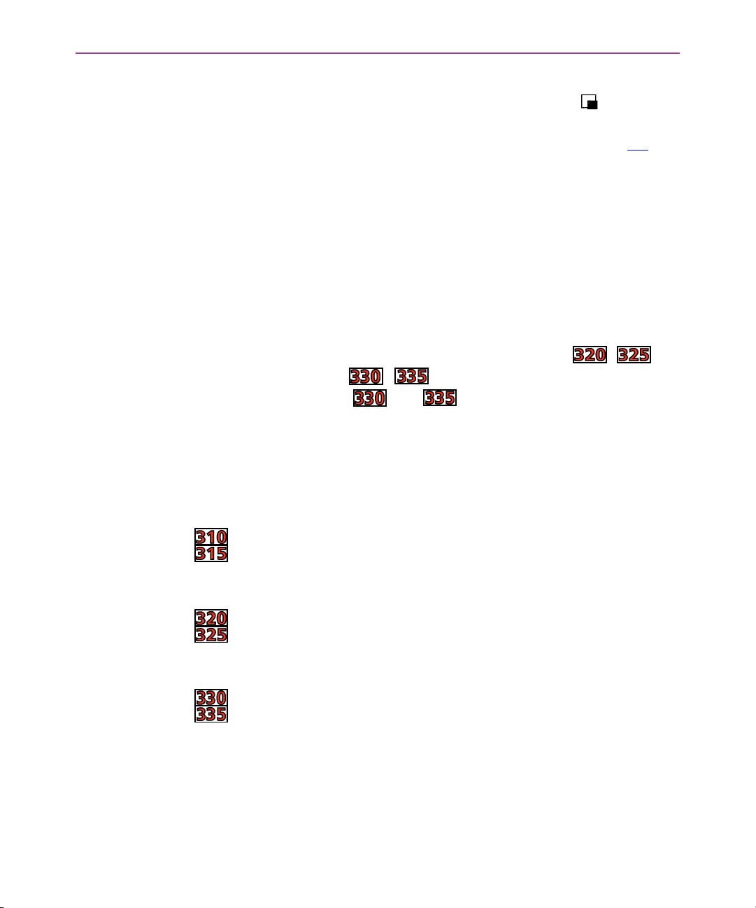
Figure 2-7: Location of the Cursor Keys in the Falcon and
) to move the display up, down, to the left, or to the
FN key, to make the current cursor position visi-
FNFN
FN key and use the cursor keys (see fig-
FNFN
FN key and then move the
FNFN
FN key again to return to the current cursor
FNFN
The key combination of FN-5
on or off.
< 22 > Falcon DOS Portable Terminals User’s Guide
FN-5 toggles the view port panning mode
FN-5FN-5
Page 35
The Viewport
G Pressing the combination FN-5
into panning mode, and the panning icon ( ) will display
along the right side of the LCD.
G Once in panning mode, the arrow keys (see figure 2-7
be used to effect panning to move the display up, down, to
the left, or to the right.
G The Panning toggle
It is not necessary to press Fn
der to exit the panning mode. Also, if any other key is pressed (besides an arrow
snap back to the cursor, and display the pressed character (if applicable).
NOTE: There is a difference in the way the Falcon , and
Falcon models , function when exiting panning mode.
On the Falcons and , once the FN-5
tered, the FN
pressing the “A” alpha key to exit panning mode will result in an “A”
being displayed.
Panning toggle key (above the 5555) can be used to exit pan-
Panning togglePanning toggle
ning mode and have the screen snap back to the cursor. In
this case, no character is displayed.
Fn to activate the Panning Toggle
FnFn
arrow key or the 5
arrowarrow
FN state is no longer active (but panning mode is), so
FNFN
5 key), the Falcon will exit panning mode,
5 5
FN-5 the first time places the unit
FN-5FN-5
) can
Panning Toggle key in or-
Panning TogglePanning Toggle
FN-5 combination is en-
FN-5FN-5
Adjusting the
Contrast
When working in dim or bright light, it is possible to adjust the contrast between the text and the background in the viewport.
G Press and release the FN 2
G Use the Light
G When finished, press and release the FN 2
G Press and release the FN
G Use the Light
G When finished, press and release the FN
G Press the Fn-Lamp
cate the contrast mode is active, two dots to the right of the
Fn
Fn Icon on the right-hand side of the display will toggle back
FnFn
and forth.
G The left
G The right
display.
Light and Dark
LightLight
Light and Dark
LightLight
Fn-Lamp key to enter contrast adjust mode. To indi-
Fn-LampFn-Lamp
left and down arrow
leftleft
right and up arrow keys
rightright
Falcon DOS Portable Terminals User’s Guide < 23 >
down arrow keys will decrease the contrast
down arrowdown arrow
FN 2 key
FN 2FN 2
Dark keys to adjust the contrast.
DarkDark
FN 2 key again.
FN 2FN 2
FN key.
FNFN
Dark keys to adjust the contrast.
DarkDark
FN key again.
FNFN
arrow keys will increase the contrast of the
arrow keysarrow keys
Page 36
Using the Falcon
Using the
Backlight
When using the Falcon in dim light, the backlight can be turned on
to improve viewport visibility.
Falcon models , , , and :
G Press the Lamp
On the Falcon model and :
G Press the Lamp
To save battery power, the backlight will shut off automatically if no
key is pressed within a certain amount of time. The backlight will
turn back on when any keypad key is pressed.
>> The Falcon Laser
Some models of the Falcon come with a built-in high-performance
laser scanner. To use this scanner, just point the laser window at a
bar code and press the trigger that activates the laser. A red lightemitting diode (LED) on the scanner module indicates when the
Falcon is scanning, and a green LED indicates when a scan is
successful.
Lamp ( ) key below the viewport to turn the
LampLamp
backlight on or off.
Lamp ( ) key in the middle of the bottom row of
LampLamp
the keypad matrix to turn the backlight on or off.
Some Falcon models are equipped with a long-range scanner. See
page 26
The Falcon and has a built-in front shooting laser.
< 24 > Falcon DOS Portable Terminals User’s Guide
for information on using the long-range scanner.
G To use the laser, aim the top of the unit at a barcode and
press the Scan
G The laser is not aimed straight from the unit, but angles
down at approximately a 15 degree angle. This allows scanning barcodes with a more natural hand position (the unit
rests more horizontally instead of angling down).
G A red LED directly below the LCD (above the F3
cates when the Falcon is scanning.
G This LED switches to green when a scan is successful.
Scan key.
ScanScan
F3 key) indi-
F3F3
Page 37
The Falcon Laser
The Laser Triggers The left trigger (as seen from the front) is the default setting to op-
erate the Falcon laser or another bar code reader attached to the
Falcon, and the right trigger toggles the Falcon in and out of Alpha
mode (models and ) or Function mode (models
and ).The operation of these triggers can be switched. This will
allows use of the right trigger as the laser trigger and the left trigger
as the mode toggle. To swap the trigger operations:
G Press the FN 2
G Repeat to return to the default settings.
FN 2 key, and then press the SWAP
FN 2FN 2
SWAP key
SWAPSWAP
G Press the FN
FN key, and then press the SWP
FNFN
SWP key
SWPSWP
G Repeat to return to the default settings.
NOTE: Unlike the Falcon and , the Falcon and
have only one laser scan
laser scan key. It is the large elliptical key in the
laser scanlaser scan
middle top of the keypad matrix. This key cannot be reprogrammed.
Changing the
Laser Module’s
Orientation
Normally, the laser window faces the left side of the Falcon for easy
right-handed scanning. To hold the Falcon in the left hand while
scanning, the laser module can be rotated.
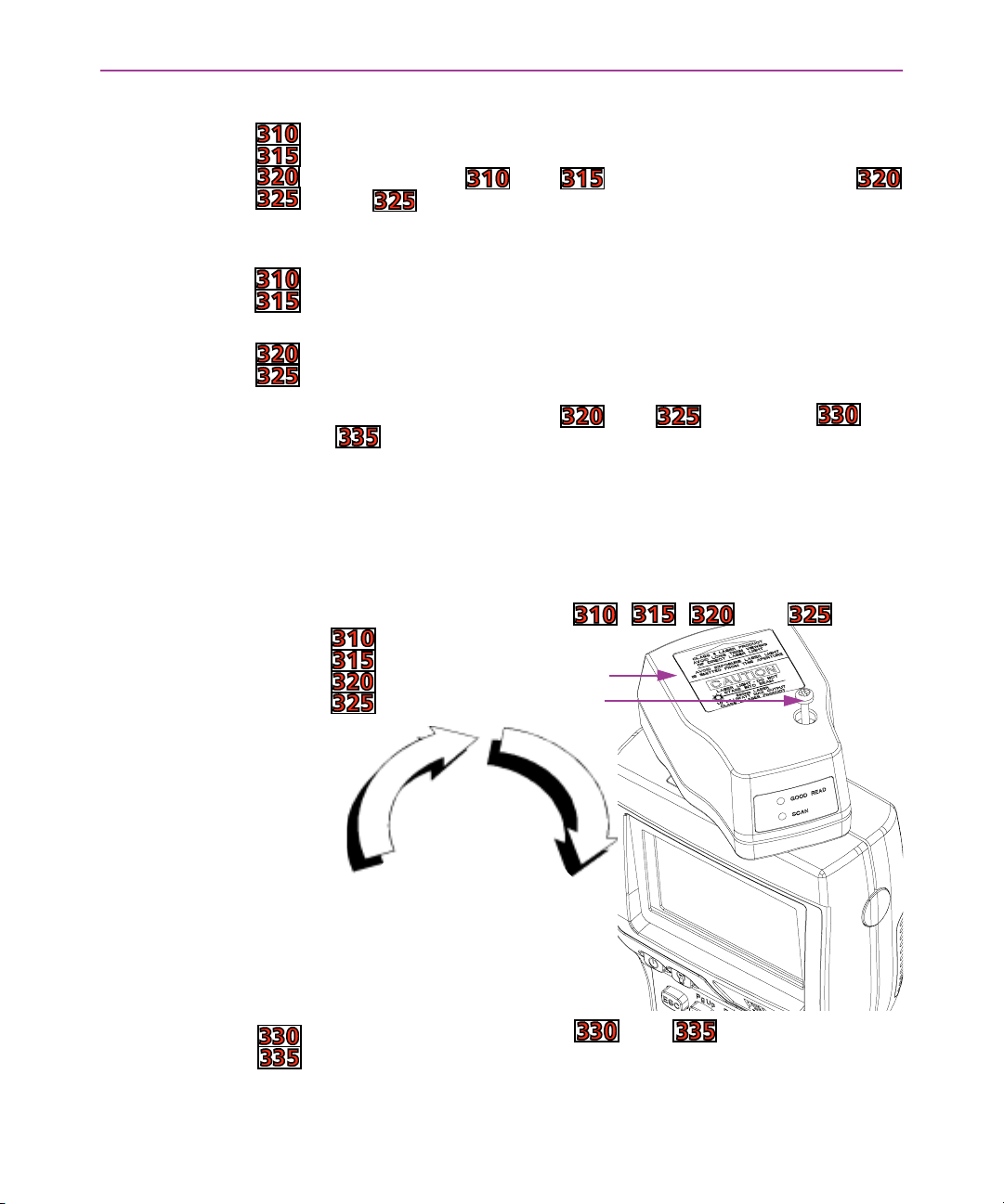
Figure 2-8: Rotating the Laser Module on the Falcon , , , and
Laser module
Screw
1. Loosen the screw.
2. Gently lift the
laser module up
from the main
unit.
3. Rotate the mod-
ule 180°.
4. Reattach the
module to the
main unit.
5. Tighten the
screw.
NOTE: The Falcon models and do not have a long
range scanner option at this time.
Falcon DOS Portable Terminals User’s Guide < 25 >
Page 38
Using the Falcon
To rotate the laser module, complete the following steps:
1. Loosen the screw that secures the module to the main part of
the Falcon (see figure 2-8
2. Gently lift the laser module away from the top of the main part
of the Falcon. The module will not completely separate from the
rest of the Falcon. Do not try to force the units apart.
3. Swivel the module around until the laser window faces the
opposite direction. The module can rotate in only one direction.
Do not force it the other way.
4. Press the laser module back into the main part of the Falcon,
and tighten the screw.
NOTE: After changing the laser module’s orientation, it may be necessary to swap the operations of the triggers (see above).
). Do not try to remove the screw.
Using the Long-
Range Laser
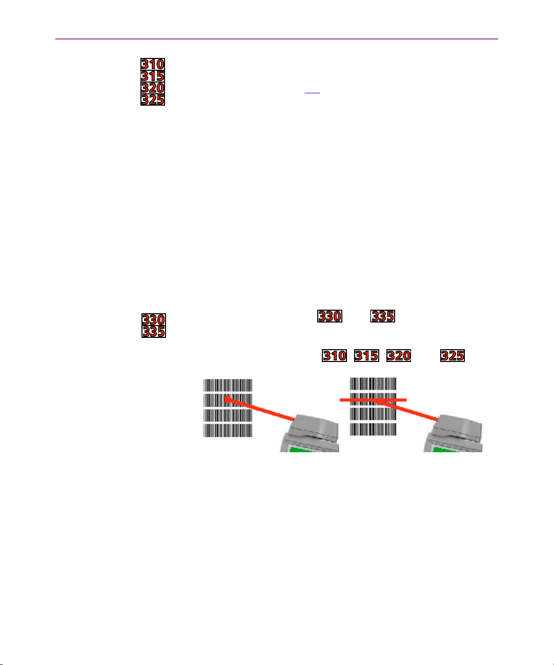
Figure 2-9: Long-Range Laser Operation in the Falcon , , , and
The Falcon’s optional long-range integrated laser uses a spotting
beam to scan bar code labels from a distance. With the spotting
beam aimed at the center of the bar code, the Falcon unit is positioned to read the bar code with its scanning beam.
NOTE: The Falcon models and do not have a long
range scanner option at this time.
Spotting beam Scanning beam
The long-range laser may be operated in either of two trigger
modes:
G Spot Beam Time-out This is the default mode of opera-
tion. When the laser trigger is pressed and held, the laser
emits a spotting beam. Aim this beam at the center of the
bar code. After a short time-out period (the default is onehalf second), the laser switches to a full scanning beam and
reads the bar code.
< 26 > Falcon DOS Portable Terminals User’s Guide
Page 39
G Release Scan This mode provides greater control over the
spotting beam. When the laser trigger is pressed and held,
the laser emits a spotting beam, as with the Spot Time-out
mode. In Release Scan mode, the spotting beam stays on,
for up to 5 seconds, until the trigger is released. Then the
laser switches to a full scanning beam and reads the bar
code. (Turn off the full scanning beam by pressing and
releasing the trigger.)
To prevent accidental scanning, both modes require that the laser
trigger is held down to activate the spotting beam.
>> Attaching a Bar Code Reader
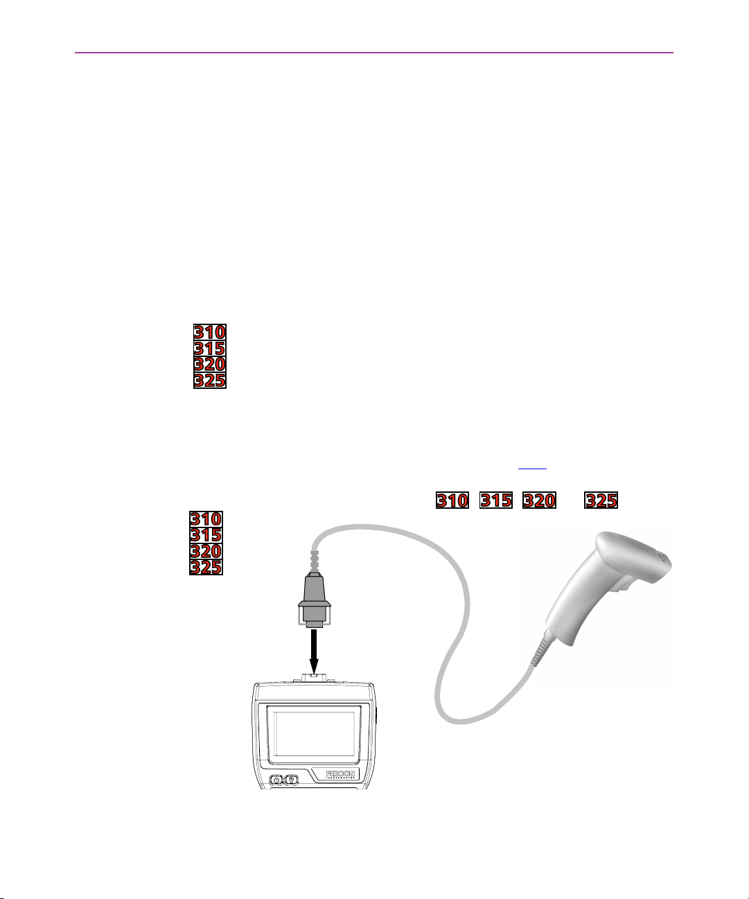
If the Falcon does not have an integrated laser scanner, a bar code
reader can be attached to the connector at the top. The reader’s
cable must have a standard nine-pin squeeze connector at the end.
To attach the bar code reader:
G Match the orientation of the holes on the squeeze connec-
tor with the pins on the Falcon’s connector.
Attaching a Bar Code Reader
G Push the squeeze connector onto the Falcon’s connector
until it is firmly in place (see figure 2-10
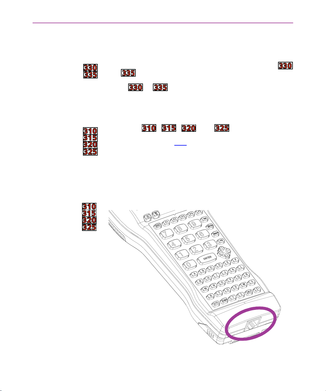
Figure 2-10: Attaching a Percon SnapShot to a Falcon , , , or
).
Falcon DOS Portable Terminals User’s Guide < 27 >
Page 40
Using the Falcon
To disconnect the bar code reader from the Falcon:
NOTE: The only option for scanning with the Falcon models
and is with the internal laser. Due to sealing and environmental issues, no external port is available for external lasers, even if the
Falcon or is ordered without an internal laser.
>> The Serial Port
The Falcon , , , and have a port for serial
communications with a PC. The port is located at the base of the
Falcon unit (see figure 2-11
telephone-style jack providing a standard RS-232 connection.
With a serial cable connected to it, the port allows communications
with a host computer or any serial device, such as a printer or modem. The serial port also provides a connection for communications
and battery recharging in the Falcon Dock and Falcon 4-Slot Dock.
G Press the sides of the squeeze connector
G Pull it away from the Falcon’s connector.
). Designated as COM1, it is a 10-pin
Figure 2-11: The Serial Port
< 28 > Falcon DOS Portable Terminals User’s Guide
Page 41

>> The Falcon Applications
When shipped from the factory, each Falcon unit is programmed
with several applications collectively known as PAL2. If the Falcon
has been customized, it may be programmed with other (or additional) applications.
For information on using PAL2, see the Falcon Portable Applications
Library User’s Guide. When using another application, contact the
system administrator for instructions.
The Falcon Applications
Falcon DOS Portable Terminals User’s Guide < 29 >
Page 42

Page 43

>> Chapter Three
The Falcon Dock
The Falcon Dock is specially designed for use with the Falcon DOS portable terminal.
The dock provides a connection between the Falcon and a computer without sacrificing the convenience of portability. Instead of attaching a cable each time to transmit data to or from the Falcon, simply place the unit into the dock. To use the Falcon
for data collection again, just remove it from the dock.
This chapter describes how to use the Falcon Dock.
CHAPTER CONTENTS
About the Falcon Dock <32>
Attaching the Falcon Dock
to the Computer <33>
The Power Adapter <33>
Using the Falcon Dock <34>
Maintenance <35>
< 31 >
Page 44
The Falcon Dock
>> About the Falcon Dock
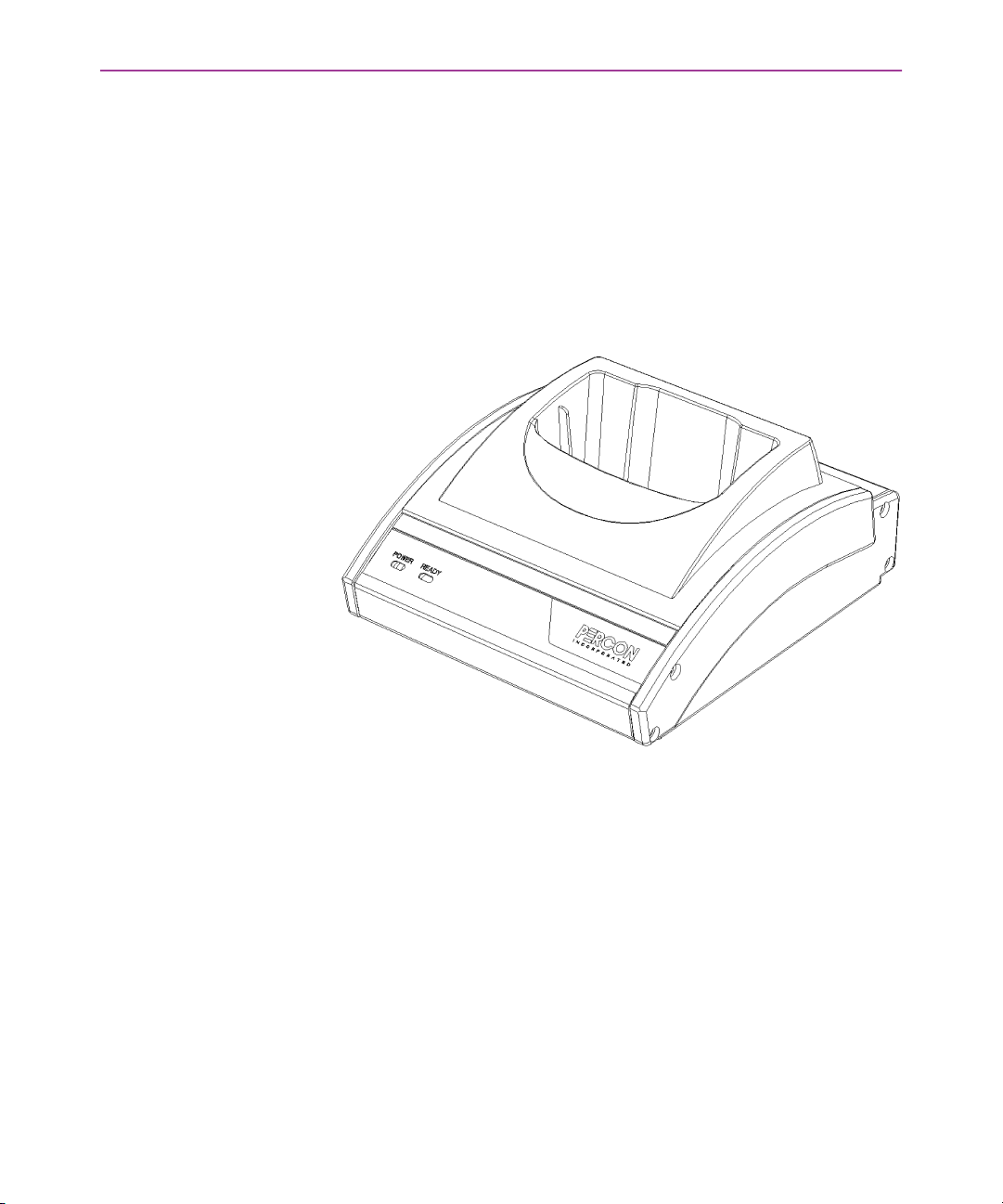
The Falcon Dock is a handy docking station for the Falcon. It has two
primary uses:
G Recharges the Falcon’s NiCD or NiMH battery pack
G Provides a connection for serial communications between
the Falcon and the host computer or another serial device,
such as a printer or modem
Figure 3-1: The Falcon Dock
A cable and a power adapter for the Falcon Dock are available separately. To make cables, see the Falcon DOS Portable Terminals Ad-
vanced User’s Guide for pin assignments.
< 32 > Falcon DOS Portable Terminals User’s Guide
Page 45
Attaching the Falcon Dock to the Computer
>> Attaching the Falcon Dock to the Computer
Complete the following steps:
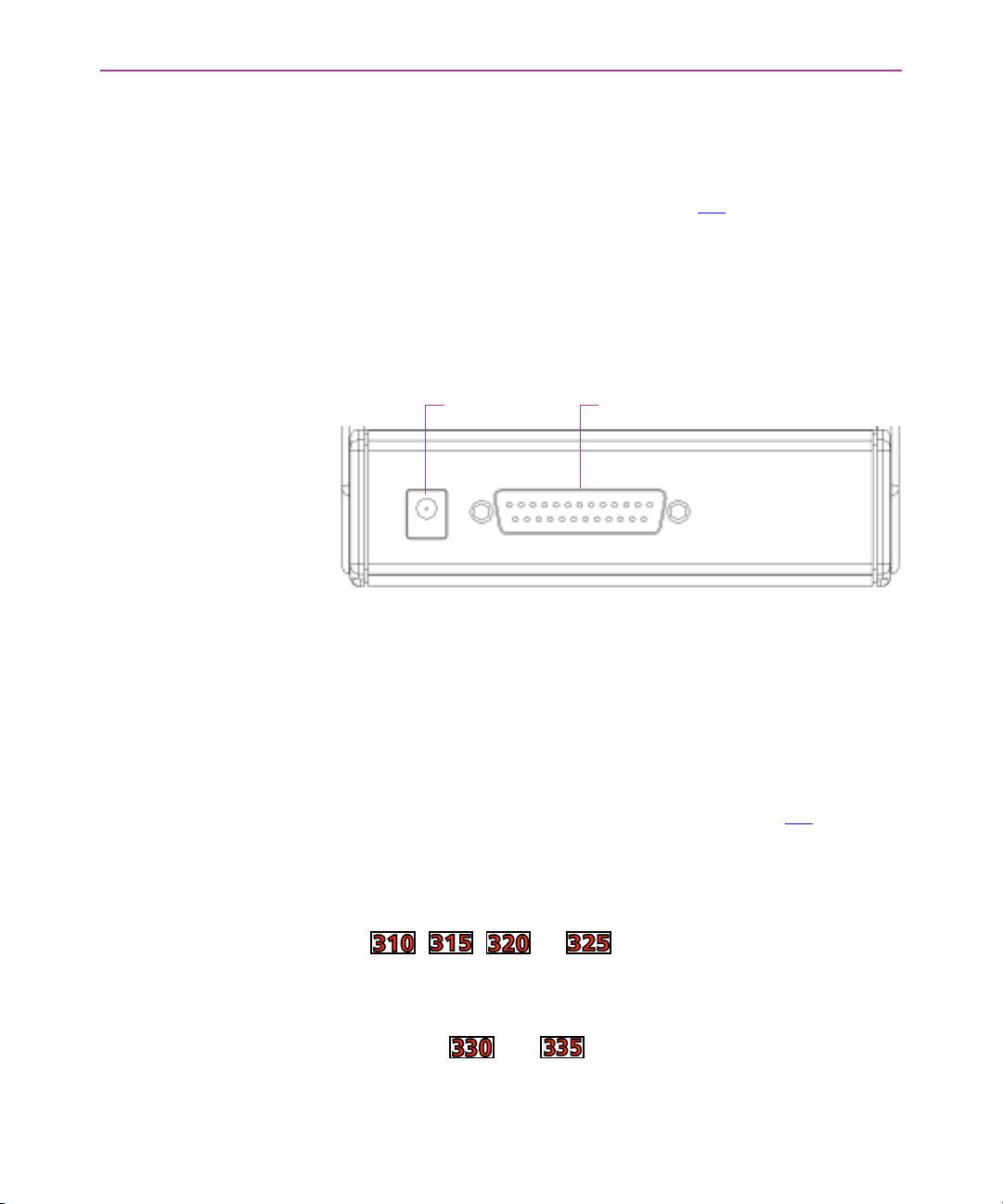
1. Attach the 25-pin end of the cable to the cable connector on
the back of the Falcon Dock (see figure 3-2
2. Attach the other end of the cable to a serial port on the selected
computer.
3. If the optional power adapter was ordered, attach it to the
Falcon Dock (see the next section).
Figure 3-2: Back Panel of the Falcon Dock
Cable connectorPower input jack
).
>> The Power Adapter
A 9-volt power adapter can be used with the Falcon Dock to recharge the NiCD or NiMH batteries in the Falcon. Power adapters are
available from a Percon dealer.
Attach the small, round plug of the power adapter to the power input jack on the back of the Falcon Dock (see figure 3-2
other end into an outlet or power strip. The red light-emitting diode
(LED) labeled
light up.
The power adapter is used only to recharge the batteries in the Falcon , , , or . However, if it is not used, the LED
indicators on the Falcon Dock will not light up. (The
cates that the Falcon is properly inserted in the dock. The
will appear red when charging and green when fully charged.)
In the Falcon and , the dock’s power must be on for serial communication to occur.
Falcon DOS Portable Terminals User’s Guide < 33 >
). Plug the
POWER on the front panel of the Falcon Dock should
READY light indi-
READY light
Page 46

The Falcon Dock
NOTE: If alkaline batteries are being used in the Falcon, do not connect a power adapter to the dock. Attempting to recharge alkaline
batteries may cause battery leakage. Use only a 9-volt power
adapter supplied by a Percon dealer. Using another adapter can
damage the dock.
>> Using the Falcon Dock
Set up the Falcon Dock as described in the preceding sections. Place
the Falcon into the dock, with the keypad facing the front. If a
power adapter is being used, the green LED labeled
front panel of the Falcon Dock should light up.
READY on the
NOTE: If the
G Make sure the
READY light does not come on:
POWER light is on
G The Falcon is fully inserted into the dock, with the keypad
facing out
READY light still does not come on:
If the
G Make sure the Falcon Dock adapter is securely attached to
the Falcon
G The contacts in the dock are clean. (If a power adapter is
not being used, the light will not come on.)
If alkaline batteries are being used in the Falcon, do not connect a
power adapter. Serial communications will operate normally even
though the indicator LEDs will remain dark without the adapter.
While the Falcon is in the Falcon Dock, programs can be downloaded into the Falcon or data returned from it just as if it were connected directly to the computer. The Falcon can be left in the dock
while using an attached bar code reader.
If utilizing a nickel-cadmium (NiCad) or nickel metal hydride (NiMH)
battery pack in the Falcon, the Falcon Dock can be used to recharge
the batteries. Simply leave the battery pack in the Falcon when placing it in the dock. The battery pack and the lithium backup battery
will be recharged while the
READY light is on. The charging time is 8
to 15 hours, depending on the type of battery pack and the current
charging level.
< 34 > Falcon DOS Portable Terminals User’s Guide
Page 47
>> Maintenance
Maintenance
NOTE: Communications between Falcon models or and
the host are exactly the same as a Falcon , or dock or a
hardwire connection with the following exceptions:
G The Falcon and uses IR for data transmission.
The dock will not propagate other RS-232 control signals
(such as RTS and CTS).
G These signals are loopbacked on the dock (CTS <-> RTS,
etc.). Applications that expect these signals will need to be
modified.
G Even though the Falcon and are IR, the dock
allows full duplex communications between the Falcon and
host.
With normal use, the Falcon Dock should require no maintenance.
Falcon DOS Portable Terminals User’s Guide < 35 >
Page 48

Page 49
>> Chapter Four
The Falcon 4-Slot Dock
The Falcon 4-Slot Dock is specially designed for use with Falcon DOS portable terminals. It provides serial communications capabilities and convenient battery recharging for one to four Falcons. This chapter describes how to set up and use the Falcon
4-Slot Dock.
Finding Out More: See the Falcon DOS Portable Terminals Advanced User’s Guide.
NOTE: There is no 4-Slot Dock for the Falcon and at this time.
CHAPTER CONTENTS
About the Falcon 4-Slot Dock <38>
Front Panel
Back Panel
Installation <40>
Power Adapter
Cables
Connecting the Dock to the Host
Creating a Dock Network
Using the 4-Slot Dock <41>
Charging a Falcon’s Batteries
Transferring Data
< 37 >
Page 50
The Falcon 4-Slot Dock
>> About the Falcon 4-Slot Dock
Use the Falcon 4-Slot Dock to:
G Provide a connection for serial communications between
one to four Falcons and a host computer.
G Recharge the Falcon’s nickel cadmium (NiCD) or nickel
metal-hydride (NiMH) battery pack.
A dock network can be used by connecting two or more 4-Slot
Docks to each other and connecting just one dock to the host. A
Falcon in any slot on any dock in the network can exchange data
with the host. While a slot is busy, all other slots in the network
must wait for that one to become free.
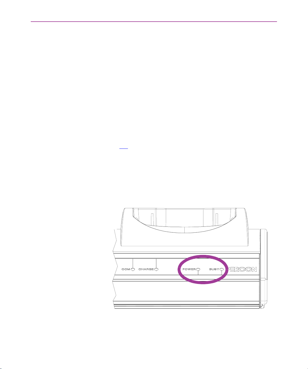
Front Panel The front panel of the 4-Slot Dock has two light-emitting diodes
(LEDs) that indicate conditions for the entire 4-Slot Dock unit (see
figure 4-1
POWER Green indicates that the dock is receiving electricity
through the power adapter.
BUSY Red indicates that another 4-Slot Dock in the network is
communicating with the host.
).
Figure 4-1: LEDs for Status of Falcon 4-Slot Dock
< 38 > Falcon DOS Portable Terminals User’s Guide
Page 51
About the Falcon 4-Slot Dock
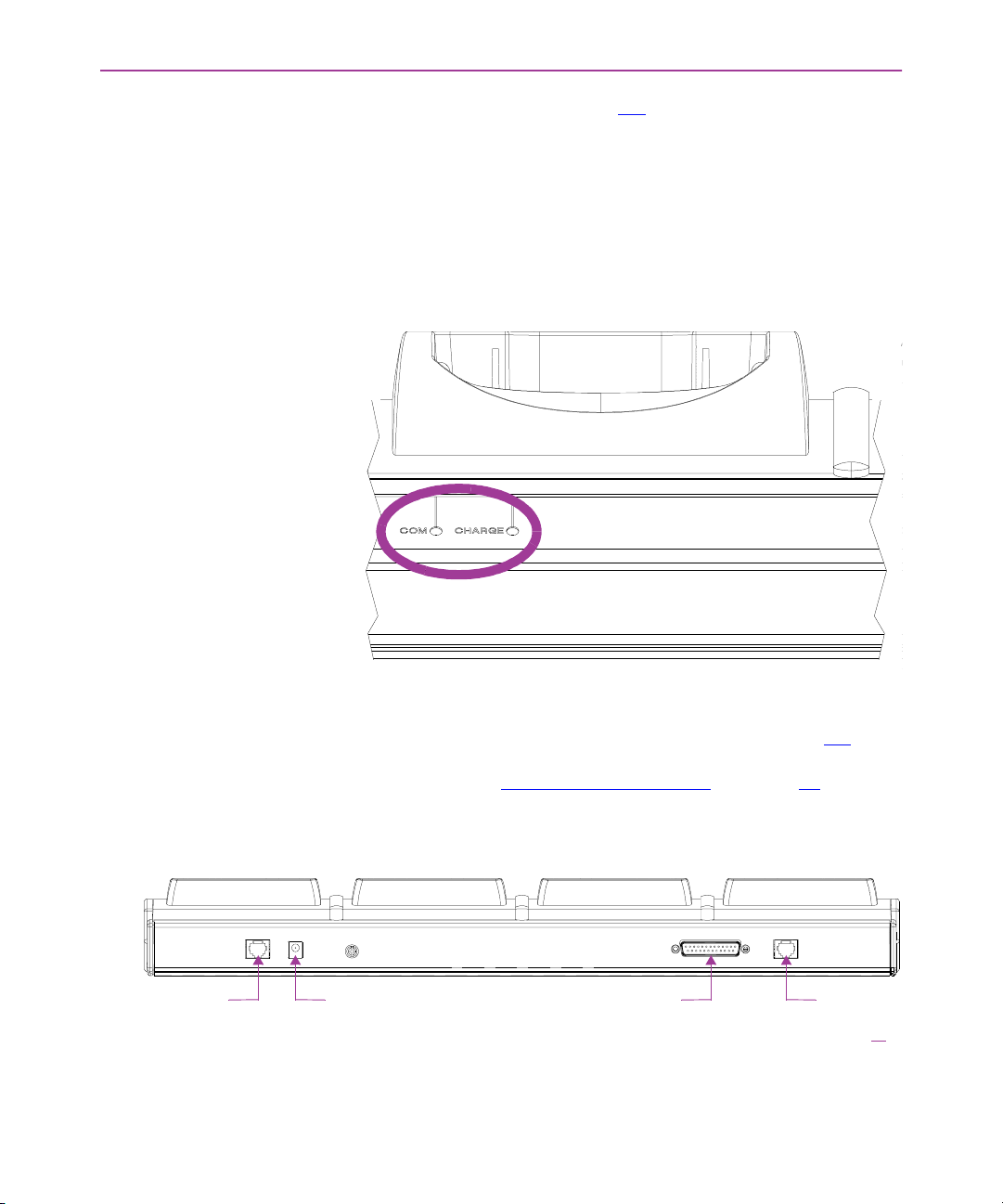
Two LEDs for each slot (see figure 4-2
portable in that slot.
COM Green indicates that the Falcon has control of the communi-
cations line to the host.
CHARGE Red indicates that the Falcon’s batteries are being
charged. Green indicates that the batteries are fully charged.
Figure 4-2: LEDs for Status of Falcon in Slot
) show the status of the Falcon
BACK PANEL The back panel of the 4-Slot Dock has cable jacks for connections to
the host computer and other 4-Slot Docks (see figure 4-3
power input jack is also located there. (For information about connecting docks, see “Creating a Dock Network
Figure 4-3: The Back Panel on the Falcon 4-Slot Dock
Connector for
dock-to-dock cable
Power input jack Connector for
Falcon DOS Portable Terminals User’s Guide < 39 >
RS-232 host cable
). The
” on page 41).
Connector
for RS-422/485
host cable or
dock-to-dock cable
Page 52

The Falcon 4-Slot Dock
>> Installation
Power Adapter Use one of the following:
G US: US style 110VAC plug (Percon part number 00-850-00)
G International: 100–250VAC 47–63Hz input with IEC320
(part number 00-851-00; includes power cord)
Cables To connect the 4-Slot Dock to a host computer, use one of the
following:
G RS-232 cable (Percon part number 00-884-32)
G RS-422/485 cable (custom-built for the application)
To form a network of multiple 4-Slot Docks, connect the docks to
each other with either of the following Percon cables:
G 2-foot cable (00-884-36)
G 10-foot cable (00-884-37)
NOTE: See the Falcon DOS Portable Terminals Advanced User’s
Guide for pin assignments.
Connecting the
Dock to the Host
< 40 > Falcon DOS Portable Terminals User’s Guide
To connect the Falcon 4-Slot Dock to a computer, complete the following steps:
1. Plug one end of the serial cable into the appropriate connector
on the back of the 4-Slot Dock.
2. Attach the other end of the cable to an available serial port on
the computer.
3. Attach the power adapter cord to the power input jack on the
back of the dock. (If using the international power adapter, plug
one end of the power cord into the power adapter.)
4. Plug the power cord into an outlet or power strip (preferably
one that has surge protection). The
panel of the dock should light up.
POWER LED on the front
Page 53
Using the 4-Slot Dock
Creating a
Dock Network
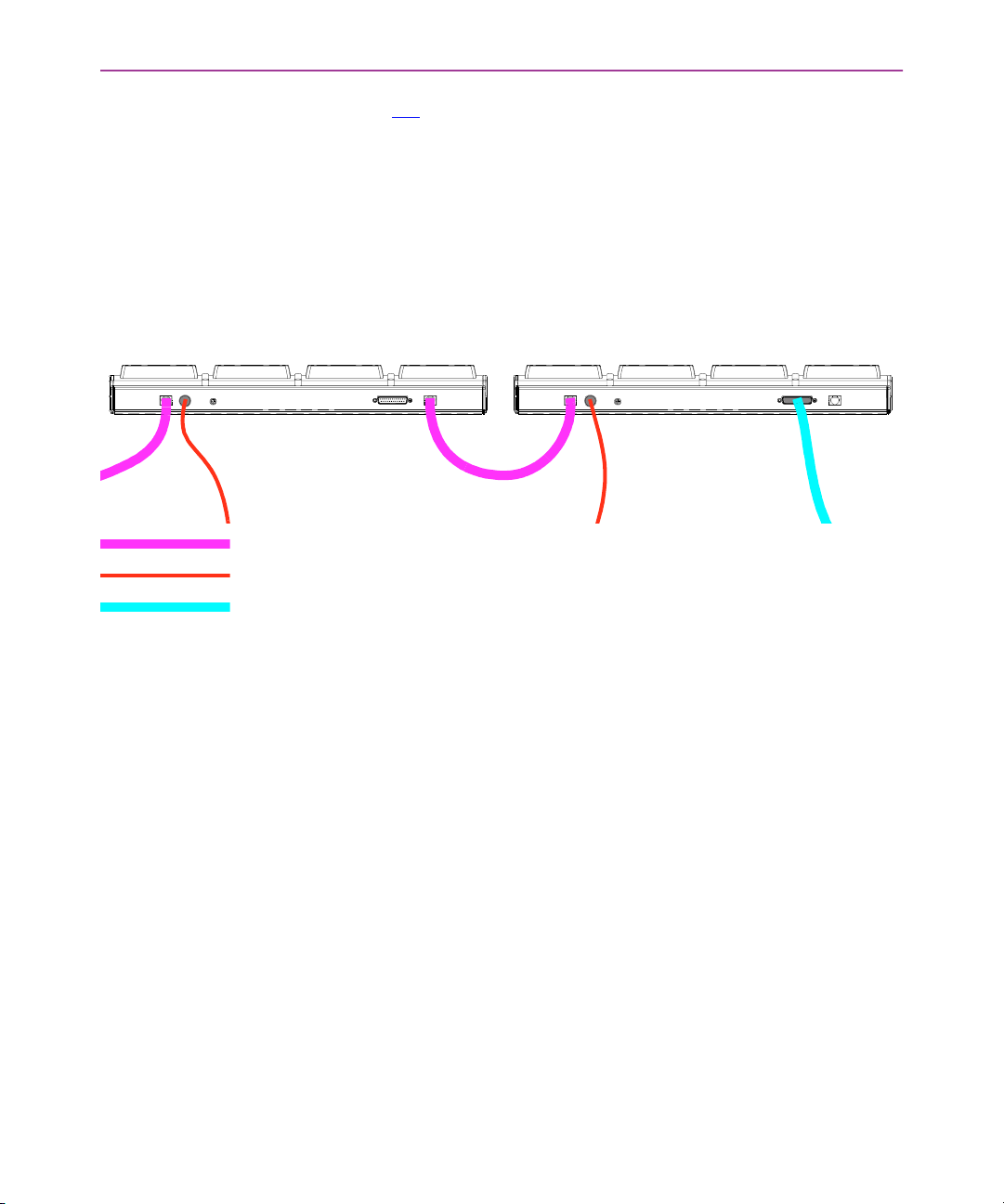
Figure 4-4: Connections for Falcon 4-Slot Docks in a Network
= DOCK-TO-DOCK CABLE
= POWER-ADAPTER CORD
= DOCK-TO-HOST CABLE
Figure 4-4 shows the back of two docks in a network. The dock on
the left is connected to a third dock (which may be connected to another dock). The dock on the right is connected to the host computer with an RS-232 cable. (To use an RS-422/485 connection to
the host, use the telephone-style jack at the far right. The RS-232
connector would not be used.)
Each 4-Slot Dock unit in the network must be connected to a power
supply.
>> Using the 4-Slot Dock
Charging a
Falcon’s Batteries
Tran sfe rri ng D ata To transfer programs or data files between a Falcon and a computer
To charge the rechargeable batteries in a Falcon, place the Falcon
into any slot of a 4-Slot Dock that is connected to a power supply.
The dock does not need to be connected to a computer.
NOTE: Only Falcons equipped with rechargeable NiCD or NiMH batteries should be used with the Falcon 4-Slot Dock. Using Alkaline
batteries can cause battery leakage and possible damage to the Falcon.
through a 4-Slot Dock, a Percon’s XFER utility can be used, the Falcon Configuration Utility, or any standard serial-transfer program.
NOTE: For information about using XFER or the Falcon Configuration Utility, see the Falcon DOS Portable Terminals Advanced User’s
Guide.
Falcon DOS Portable Terminals User’s Guide < 41 >
Page 54

Page 55
>> Chapter Five
Vehicle Mount Powered Dock
The Vehicle Mount Powered Dock is designed for road vehicles such as step vans or
semi tractors and forklifts using the optional mounting bracket. The mounting configuration is flexible to respond to the variety of vehicle configurations and personal
driver preferences. The Vehicle Mount Powered Dock functions with Falcon models
and with or without an integrated laser. Falcon models and
without an integrated laser will also work on the Vehicle Mount Powered Dock.
NOTE: There is no Vehicle Mount Powered Dock for Falcon models and .
CHAPTER CONTENTS
About the Vehicle Mount
Powered Dock <38>
Using the Vehicle Mount
Powered Dock <39>
Installation <40>
Quick Start
Vehicle 12VDC Connection
Fuse Replacement
Falcon Vehicle Bracket
Custom Mounting Brackets
< 43 >
Page 56
Vehicle Mount Powered Dock
>> About the Vehicle Mount Powered Dock
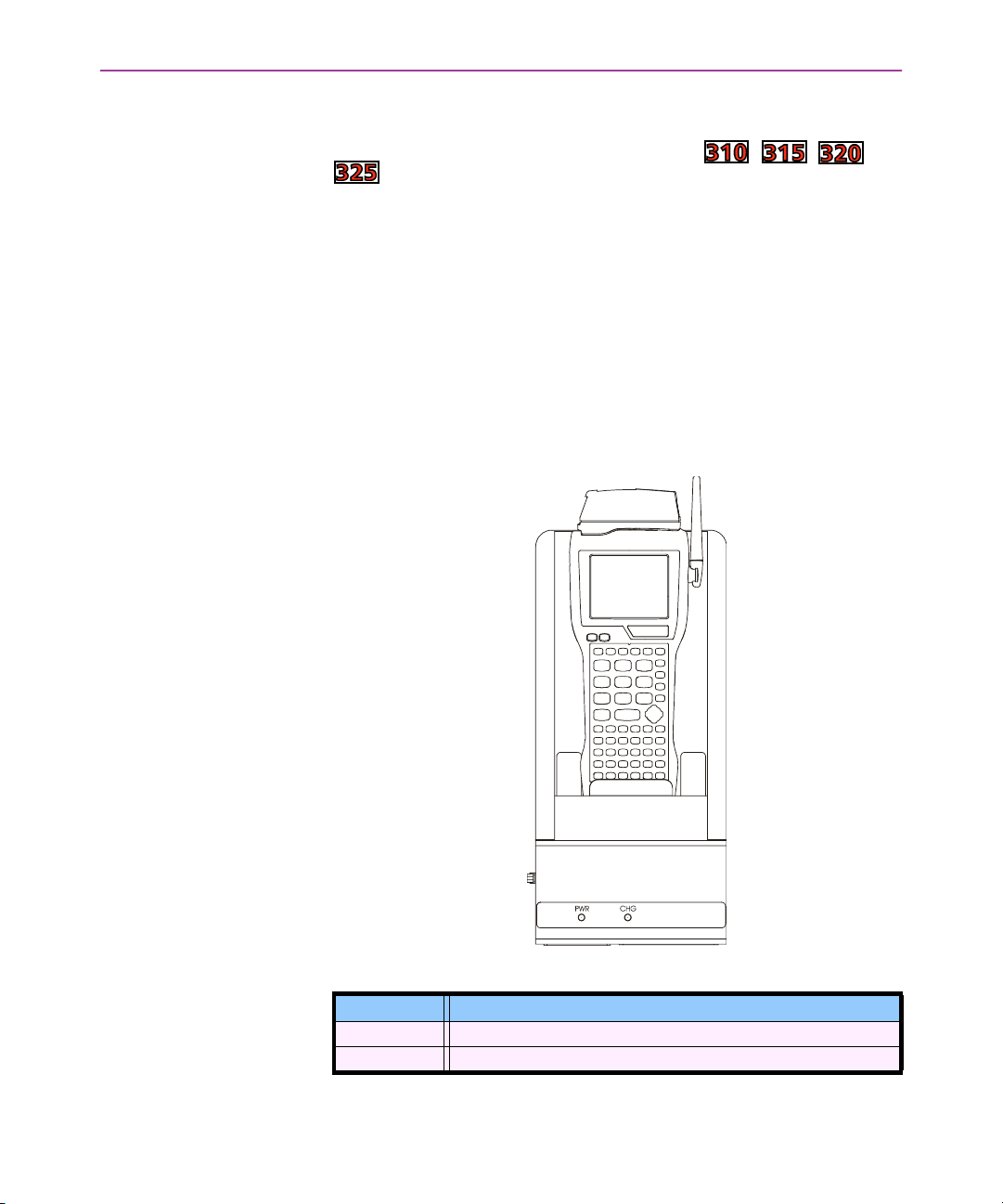
The vehicle-mounted dock holds the Falcon , , and
. The powered docking station has two primary uses:
G Recharge the NiMH battery pack(s) and lithium backup bat-
teries.
G Provide a connection for serial communications between
the Falcon and the host computer or another serial device,
such as a printer or modem.
G AC Power supplies are available that meet either 110V -
120V or 200V - 240V.
The Vehicle Mount Powered Dock requires a DC power source within
the range of 11 V to 16.5 V.
Figure 4-1: Dock in Vehicle Mounting Bracket
Table 1-1: Indicators and Functions
Indicator Function
PWR (Power) Green when receiving power from a vehicle battery.
CHG (Charge) Green when charging the main and backup batteries in the Falcon.
< 44 > Falcon DOS Portable Terminals User’s Guide
Page 57
Using the Vehicle Mount Powered Dock
>> Using the Vehicle Mount Powered Dock
NOTE: The Power LED on the dock is illuminated when the dock is
receiving DC power. Batteries in the Falcon will not charge unless
the Power LED is on.
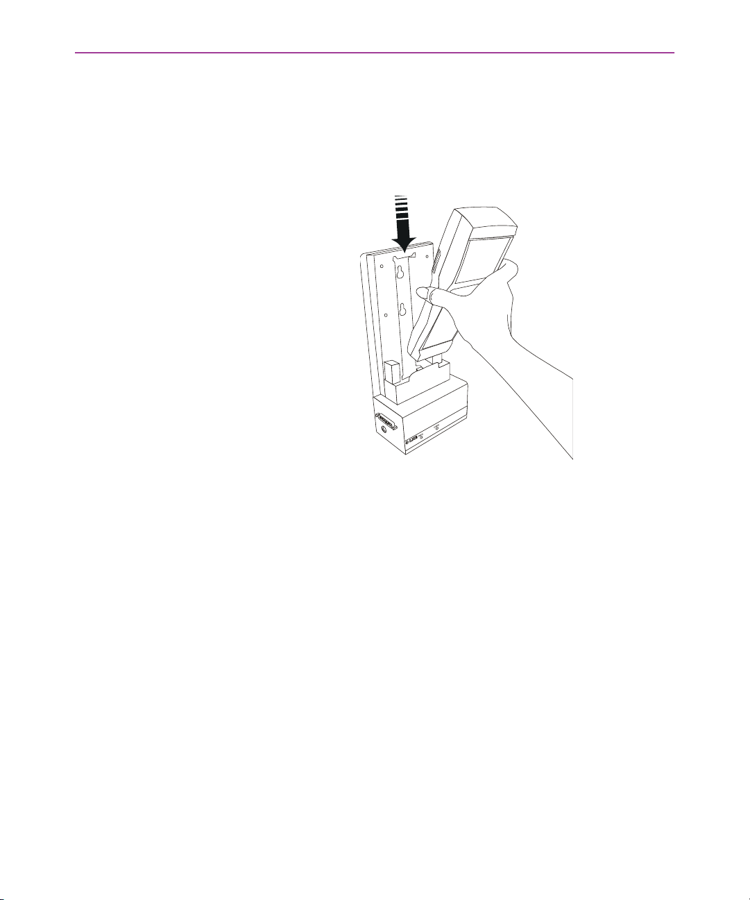
Figure 4-1: Insert the Falcon in Vehicle Mount Powered Dock.
NOTE: Percon recommends the Falcon be inserted in the dock after
the dock is securely mounted to a vehicle.
1. Place the Falcon in the dock with the keypad facing out (on the
same side as the indicators).
2. Push the Falcon down into the well and release. The hand strap
hook will connect with the upper tab, securing the Falcon in the
dock. (See arrow in figure titled "Insert Falcon in Vehicle Mount
Powered Dock.")
3. The dock will begin charging the batteries. The Falcon can begin
communicating with another serial device, such as a printer or
modem.
4. Please refer to the “Falcon Advanced User’s Guide” for instruc-
tions on sending data to and from a printer or modem.
Falcon DOS Portable Terminals User’s Guide < 45 >
Page 58

Vehicle Mount Powered Dock
>> Installation
NOTE: If the Falcon contains non-rechargeable batteries, do not
connect the power supply to the dock.
Hardware and tools needed for attaching the vehicle mounting
bracket to the vehicle are not supplied by Percon.
Quick Start Though Percon does offer a mounting bracket that provides vibra-
tion isolation (recommended for forklifts), custom bracket or offthe-shelf cell phone mounting equipment can also be used. The following instructions use the Powered Dock Mounting bracket. See
Figure 4-7:
the mounting pattern if using a custom mount.
1. Assemble mounting bracket.
2. Install mounting bracket on a stable, flat surface. Use the Pow-
3. Insert the Falcon in the dock bracket assembly.
4. Connect power source to the dock.
5. Dock Power LED illuminates.
6. Turn the Falcon on.
Back view of dock before mounting custom bracket for
ered Dock mounting bracket or an equivalent mounting assembly.
Vehicle 12VDC
Connection
< 46 > Falcon DOS Portable Terminals User’s Guide
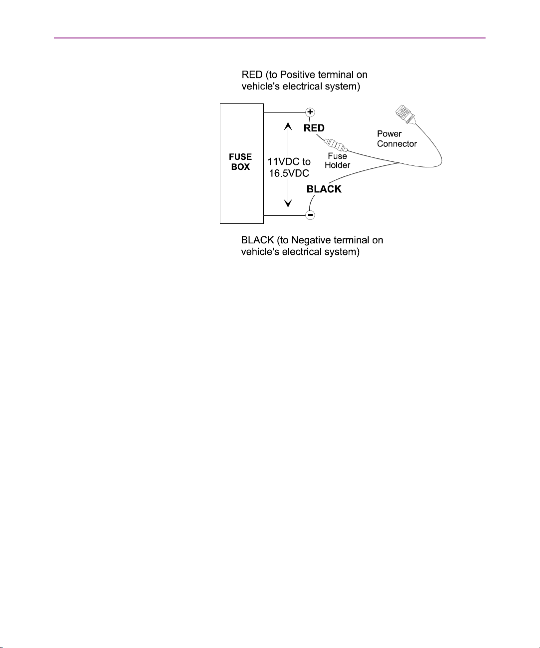
The dock is designed for use with any automotive DC power source
within the range of 11 V to 16.5 V.
It is recommended that the vehicle cable be connected to an unswitched outlet on the vehicle’s fuse box. This connection method
reduces the chance of interference from the vehicle’s charging system.
Page 59
Installation
Figure 4-2:
.Proper Connection of the Vehicle Cable
Caution: Correct electrical polarity and grounding is required for
safe and proper installation. Only connect to a negative ground DC
supply circuit. This is not for installation to positive ground circuits.
When the dock is connected to an unswitched outlet on the fuse
box the Falcon battery will always receive a charge from the vehicle
battery. If the unit is left turned on for extended periods of time, the
Falcon could drain the vehicle battery.
If the dock is connected to a switched outlet on the fuse box, the
Falcon, battery will only charge when the vehicle is on. This will
eliminate the problem of draining the vehicle battery.
Fuse Replacement The unit uses a 250V, 1.5A (fast blow), high current interrupting
rated fuse that is externally accessible and user replaceable. Should
it need replacement, replace with same size, rating and type of fuse
(such as Bussman AGC-1 1/2).
Powered Dock
Mounting Bracket
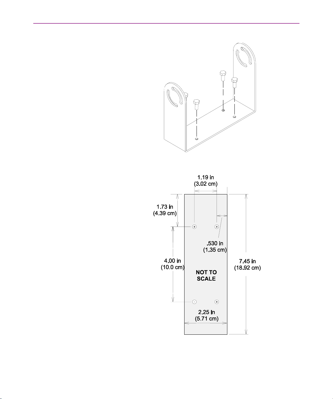
Install the Bottom Mounting Bracket portion of the mounting assembly to the vehicle using ¼” (6.35mm) maximum diameter fasteners (not supplied by Percon).
Falcon DOS Portable Terminals User’s Guide < 47 >
Page 60
Vehicle Mount Powered Dock
Figure 4-3: Bottom Mounting Bracket.
Figure 4-4:
.Powered Dock Bracket Mounting Pattern
Fasten the back plate assembly to the dock using the through holes
in the back plate and the threaded holes in the back of the dock.
Four #8-32 fasteners are provided with the mounting kit.
< 48 > Falcon DOS Portable Terminals User’s Guide
Page 61
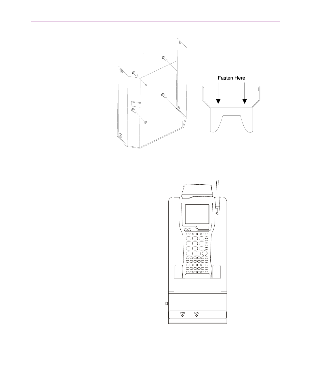
Figure 4-5: Fasten Back plate Assembly to dock
The dock is ready for cabling.
Figure 4-6: Dock in Vehicle Mounting Bracket
Installation
Falcon DOS Portable Terminals User’s Guide < 49 >
Page 62
Vehicle Mount Powered Dock
Custom Mounting
Brackets
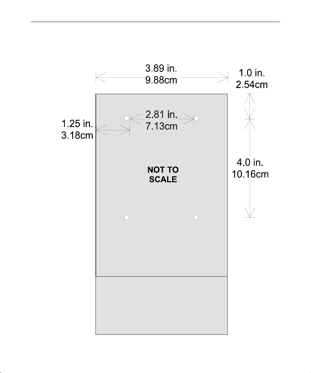
Figure 4-7: Back view of dock before mounting custom bracket
When using a non-Falcon mounting bracket, use these dimensions
when placing the OEM bracket on the dock.
< 50 > Falcon DOS Portable Terminals User’s Guide
Page 63

>> Chapter Six
Troubleshooting Guide
This chapter provides information and direction that will be useful in resolving problems that occur in the performance of the Falcon. The purpose is to give the user the
best method to identify and eliminate problems. If the problem persists beyond the
recommended actions, use the following resources:
Getting Help
The most comprehensive source for technical support and information for Percon
products is the Percon web site, at www.percon.com
frequently asked questions (FAQs), software updates, patches, demos, product documentation, and instructions for returning products for repair.
Another excellent source for technical assistance and information is an authorized
Percon reseller. A reseller is directly acquainted with specific types of business, application software, and computer system and, therefore, is in the best position to provide individualized assistance.
If the solution to a technical support question is not available through the Percon
Web site or a local reseller, contact Percon technical support directly via e-mail at
.
. The site offers answers to
CHAPTER CONTENTS
Serial Communications <44>
Bar Codes <44>
Batteries <45>
< 51 >
Page 64

Troubleshooting Guide
>> Serial Communications
Data transfer
doesn't succeed
>> Bar Codes
Bar code won't
scan
Bar code won't
scan with laser
G Do communications parameters agree (COM port, baud
rate, transfer protocol)?
G Is the cable designed for use with the Falcon (Percon-spe-
cific RJ cable) or the dock (25-pin null modem cable)?
G Is there disk drive space available on the receiver for the file
being sent? If not, delete unnecessary files.
G Check the quality of the bar code. Labels which are faded or
scratched are less likely to scan.
G Verify that the unit is configured to read the type of bar
code being scanned. Scan the D1 (see page 140
con Advanced User’s Guide) parameter and try again.
G When an attached scanning device isn’t functioning cor-
rectly, verify it is not broken by using another device.
G Vary the scanning angle and distance. Avoid aiming the
laser beam perpendicular to the bar code label or at
extreme angles.
in the Fal-
G Verify that the laser beam is intersecting the entire bar code
label.
Bar code won't
scan with wand
< 52 > Falcon DOS Portable Terminals User’s Guide
G Ensure that the wand is passing over the entire bar code
label. Holding the wand like a pencil in front of the left side
of the label, use a swift sweeping motion to move the wand
towards the other end of the label.
Page 65

>> Batteries
Unit won't turn on G Replace with a fully charged battery.
G Close the battery door securely.
Data is lost G Turn the unit off and wait for the "Powering Down" screen
to disappear before replacing batteries.
G Never leave the unit for an extended period of time without
a main battery pack.
Batteries
Unit turns off
unexpectedly and
won't turn on
G The battery is likely too weak to continue operating the
unit. Replace the main battery pack with a fully charged
battery and then turn the unit on.
Falcon DOS Portable Terminals User’s Guide < 53 >
Page 66

Page 67

Index
4-Slot Dock 3, 37–41
A
accessories 2
applications 29
auto-shutoff feature 10
B
backlight 24
backup battery 7
bar code reader, attaching to Falcon 27
bar codes
troubleshooting 52
Batteries 53
batteries
charging 2
low-battery warning 7
replacing 53
troubleshooting 53
types 7
battery charger 3
battery icon 7
, 3
C
cable
troubleshooting 52
care and cleaning 3
character set, international 18
charging batteries 2, 3
communications parameters
troubleshooting 52
communications, serial
port 28
contacting Percon iv, 51
contrast (viewport) 23
cursor keys 21, 22
cursors 16, 17
D
data transfer
troubleshooting 52
disk icon 18
display see viewport
dock
Falcon 4-Slot Dock 3
Falcon Dock 2, 31–35
troubleshooting 52
Vehicle Mount Powered 43
assembly 49
back view 50
bracket 47
bracket mounting pattern 48
connecting 47
custom brackets 50
Functions 44
fuse replacement 47
Indicators 44
installing 46
models 43
mounting bracket 48
, 37–41
Falcon DOS Portable Terminals User’s Guide < 55 >
Page 68

Index
power supplies 44
recharging batteries 44
serial communications 44
uses 44
using 45
E
e-mail address for Percon iv, 51
F
Falcon
4-Slot Dock 3
accessories for 2
applications 29
attaching scanner to 27
automatic shutoff 10
batteries 7
charging 2, 3
care and cleaning of 3
communications port 28
dock 2, 31–35
keypad 10–20
labeling v
laser 24–27
changing orientation 25
long-range 26
triggers 25
PAL 29
serial port 28
turning on and off 6
viewport 21–24
FCC information vi
4-Slot Dock 3, 37–41
, 37–41
H
help iv, 51
I
icons 16, 17
battery 7
input modes 14
integrated laser see laser
international character set 18
K
keypad 10–20
cursor keys 21, 22
input modes 14
international characters 18
repeating keystrokes 20
keystrokes, repeating 20
L
labels on Falcon v
laser 24–27
long-range 26
module, changing orientation of 25
triggers 25
light (viewport) 24
lithium battery 7
long-range laser 26
low-battery warning 7
M
modes, input 14
moving the viewport display 21
G
getting help iv, 51
< 56 > Falcon DOS Portable Terminals User’s Guide
Page 69

Index
O
on/off key 11, 12, 21, 22
orientation of laser module, changing 25
P
PAL 29
Percon, contacting iv, 51
port, serial 28
position of laser module 25
power key 6, 11, 12, 21, 22
power management 10
powering unit on
troubleshooting 53
product labeling v
purchasing accessories 3
R
repeating keystrokes 20
S
scanner, attaching to Falcon 27
see also laser
serial communication
incomplete 52
troubleshooting 52
serial communications
port 28
serial port 28
shutoff, automatic 10
support iv, 51
T
technical support iv, 51
timer, auto-shutoff 10
triggers, laser 25
troubleshooting guide 51–53
bar codes 52
batteries 53
cable 52
communications parameters 52
data transfer 52
dock 52
replacing batteries 53
unit won’t turn on 53
unsuccessful data transfer 52
V
Vehicle Mount Powered Dock 43
assembly 49
back view 50
bracket 47
bracket mounting pattern 48
connecting 47
custom brackets 50
Functions 44
fuse replacement 47
Indicators 44
installing 46
models 43
mounting bracket 48
power supplies 44
recharging batteries 44
serial communications 44
uses 44
using 45
viewport 21–24
backlight 24
contrast 23
cursors in 16, 17
icons in 16, 17
Falcon DOS Portable Terminals User’s Guide < 57 >
Page 70

W
web site, Percon iv, 51
window see viewport
Page 71

Page 72

Corporate Headquarters
Percon Incorporated
1800 Millrace Drive
Eugene, OR 97403
Voice: (541) 344-1189
Fax: (541) 344-1399
E-mail: [email protected]
Web: www.percon.com
European Headquarters
Percon Europe, S.A.
13, avenue Gabriel
78170 La Cell Saint Cloud
France
Tel: +33 01 30 78 44 80
Fax: +33 01 39 18 53 94
©2000 Percon Incorporated. Printed in the USA. April
2000. Falcon is a trademark and Percon is a registered
trademark of Percon Incorporated. Other brand and product names are trademarks and registered trademarks of
their respective owners. In a continuing effort to improve
our products, Percon reserves the right to change specifications and features without prior notice.
9720-0641-06
9720-0641-06
 Loading...