

Ultrasonic sensor UC800-F77S-EP-IO-V31
Model Number
UC800-F77S-EP-IO-V31
Single head system
Features
• IO-link interface for service and
process data
• Programmable via DTM with
PACTWARE
• Continuous distance value via IOLink process data
• Selectable sound lobe width
• Synchronization options
• Temperature compensation
• Push-pull output
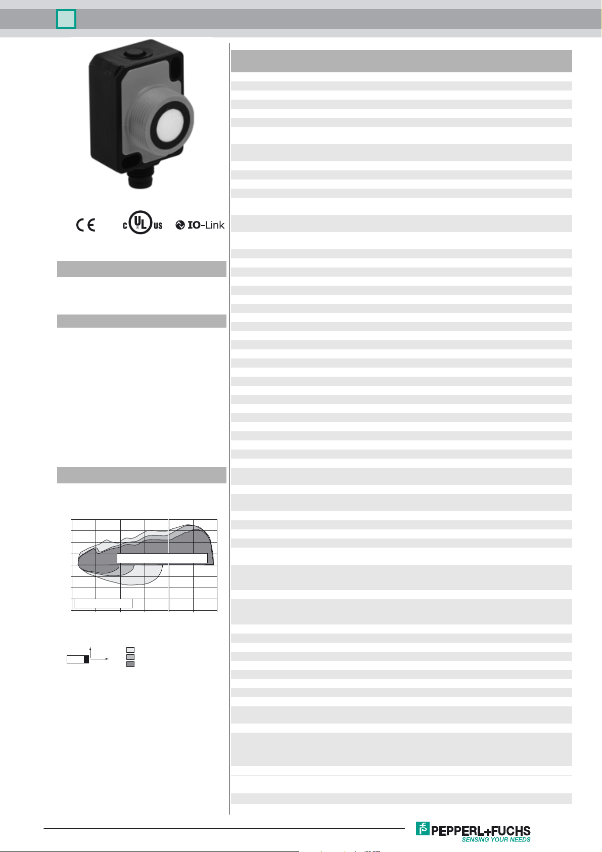
Diagrams
Characteristic response curve
Distance Y [mm]
200
150
100
50
0
-50
-100
-150
round bar, Ø 25 mm
-200
0 200 400 600 800 1000 1200
Release date: 2018-04-18 13:58 Date of issue: 2018-04-18 261244_eng.xml
Refer to “General Notes Relating to Pepperl+Fuchs Product Information”.
flat surface 100 mm x 100 mm
Y
wide sound beam
medium-sized sound beam
X
narrow sound beam
Distance X [mm]
Technical data
General specifications
Sensing range 60 ... 800 mm
Adjustment range 70 ... 800 mm
Dead band 0 ... 60 mm
Standard target plate 100 mm x 100 mm
Transducer frequency approx. 255 kHz
Response delay minimum : 13 ms
Sensor cycle time ≥ 13 ms (factory setting) ;
Memory
Non-volatile memory EEPROM
Write cycles 300000
Indicators/operating means
LED green solid: Power on
LED yellow solid: object in evaluation range
LED red solid: error
Electrical specifications
Operating voltage U
No-load supply current I
Power consumption P
Time delay before availability t
Interface
Interface type IO-Link (via C/Q = Pin 4)
Device profile Smart Sensor
Transfer rate COM 2 (38.4 kBaud)
IO-Link Revision 1.1
Min. cycle time 2.3 ms
Process data witdh 16 bit
SIO mode support yes
Device ID 0x300302 (3146498)
Compatible master port type A
Input/Output
Input/output type 1 synchronization connection, bidirectional
0 Level 0 ... 1 V
1 Level 2.5 V ... U
Input impedance > 22 kΩ
Output rated operating current current source < 2.5 mA
Pulse length ≥ 1 ms with external control, low active
Synchronization frequency
Common mode operation ≤ 82 Hz
Multiplex operation ≤ 82 Hz / n , n = number of sensors , n ≤ 10
Output
Output type 1 push-pull (4 in 1) output, short-circuit protected, reverse
Rated operating current I
Voltage drop U
Repeat accuracy ≤ ± 0.1 % of full-scale value
Switching frequency f factory setting: 12 Hz programmable max. 27 Hz
Range hysteresis H 1 % of the adjusted operating range (default settings),
Temperature influence ≤ ± 0.75 % of the end value (with temperature compensation)
Ambient conditions
Ambient temperature -25 ... 70 °C (-13 ... 158 °F)
Storage temperature -40 ... 85 °C (-40 ... 185 °F)
Mechanical specifications
Connection type Connector plug M8 x 1 , 4-pin
Degree of protection IP67
Material
Housing Polycarbonate
Transducer epoxy resin/hollow glass sphere mixture; polyurethane foam
Installation position any position
Mass 13 g
Tightening torque, fastening screws with M3 nuts max. 0.2 Nm
Factory settings
Output near switch point: 70 mm
Beam width wide
Compliance with standards and
directives
Standard conformity
B
0
0
v
e
d
factory setting: 49 ms
programmable to 60 s
flashing: Standby mode or IO-Link communication
flashing: switch point programming, object detected
flashing: switch point programming, object not detected
10 ... 30 V DC , ripple 10 %
≤ 40 mA
≤ 400 mW
≤ 300 ms
B
polarity protected
100 mA , short-circuit/overload protected
≤ 2.5 V
programmable , min. 1 mm
from 10 minutes after switching on the sensor ; 0,17 %/K
(without temperature compensation)
When fixing with one M18 nut, the temperature range begins
with 0°C (32°F).
with M18 nuts max. 1 Nm
far switch point: 800 mm
Output mode: Window mode
Output logic: normally open
SS
1
Ultrasonic sensor UC800-F77S-EP-IO-V31
Standards EN 60947-5-2:2007+A1:2012
Approvals and certificates
UL approval cULus Listed, Class 2 Power Source
CCC approval CCC approval / marking not required for products rated ≤36 V
IEC 60947-5-2:2007 + A1:2012
IEC 61131-9:2013
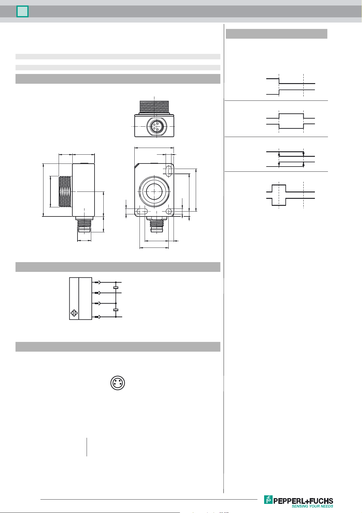
Dimensions
23
3.2
ø3.2
25
22
3
31
M18 x 1
8 13
14.6
3.2
Additional Information
Switching output modes
1. Switch point mode
Switch point 1
(SP 1)
Normally open
Normally closed
2. Window mode
Normally open
Normally closed
3. Hysteresis mode
Normally open
Normally closed
4. Retroreflective mode
Normally open
Normally closed
Switch point 2
(SP 2)
Electrical Connection
*if not used connect to ground (0V)
Pinout
M8 x 1
9
1
2
4
3
24
13
14
17
L+
Synchronization*
C/Q (Switching output/
IO-Link Interface)
L-
3
Wire colors in accordance with EN 60947-5-2
1 BN
2 WH
3 BU
4 BK
Refer to “General Notes Relating to Pepperl+Fuchs Product Information”.
(brown)
(white)
(blue)
(black)
Release date: 2018-04-18 13:58 Date of issue: 2018-04-18 261244_eng.xml
2

Ultrasonic sensor UC800-F77S-EP-IO-V31
Accessories
IO-Link-Master02-USB
IO-Link master, supply via USB port or separate power supply, LED indicators, M12
plug for sensor connection
V31-GM-2M-PVC
Female cordset, M8, 4-pin, PVC cable
V31-GM-1M-PVC-V1-G
Double-ended cordset, M8 to M12
OMH-ML7-01
Mounting aid for ML7 and ML8 series, Mounting bracket
OMH-ML7-02
Mounting aid for ML7 and ML8 series, Mounting bracket
Description of Sensor Functions
Adjustment possibilities
The sensor features a switching output with 2 programmable switch points. Programming the switch points, the output mode, the output logic and
the beam width can be done in two different ways:
- Using the sensor’s programming button
- Using the IO-link interface of the sensor. This method requires an IO-link master (e.g. IO-link-Master02-USB) and the associated software.
The download link is available on the product page for the sensor at www.pepperl-fuchs.
Synchronization
The sensor features a synchronization input for suppressing ultrasonic mutual interference („cross talk“).
The following synchronization modes are available:
1. Automatic multiplex mode.
2. Automatic common mode
3. Externally controlled synchronization
Further Documentation
- For information on programming via programming button and synchronisation you may refer to the commissioning instruction.
- For detailed information on application and programming via IO-Link we provide a manual.
Release date: 2018-04-18 13:58 Date of issue: 2018-04-18 261244_eng.xml
Refer to “General Notes Relating to Pepperl+Fuchs Product Information”.
3
 Loading...