

Ultrasonic sensor, transmitter UBE15M-H1
Technical data
General specifications
Sensing range 0 ... 15000 mm , emitter - receiver synchronised
Transducer frequency approx. 40 kHz
Angle of divergence ± 45 ° at -6 dB
Model Number
UBE15M-H1
Multi-head system
Temperature drift of echo propagation
delay
Electrical specifications
Operating voltage U
No-load supply current I
Input
Input type 1 pulse input for transmitter pulse, activation through open
Pulse length 100 µs ... 10 ms
Pause length ≥ 50 x pulse length
Ambient conditions
Ambient temperature 0 ... 50 °C (32 ... 122 °F)
Storage temperature -40 ... 85 °C (-40 ... 185 °F)
Mechanical specifications
Degree of protection IP00
Connection Contact plugs and soldering surfaces
Mass 20 g
Dimensions Printed circuit board: 45 mm x 20.2 mm (5 mm separable: 40
B
0
0.2 %/K
16 ... 30 V DC , ripple 10 %SS
8 V DC with reduced transmitting power
≤ 10 mA (typ. 6 mA at UB = 24 V DC)
collector npn
< 1.5 V: emitter active, > 3.5 V: emitter inactive
mm x 20.2 mm)
overall height: 10 mm
Features
• Large sensing range
• Large possible lateral distance
between emitter and receiver
• One or two transducers connectable
• Separate evaluation
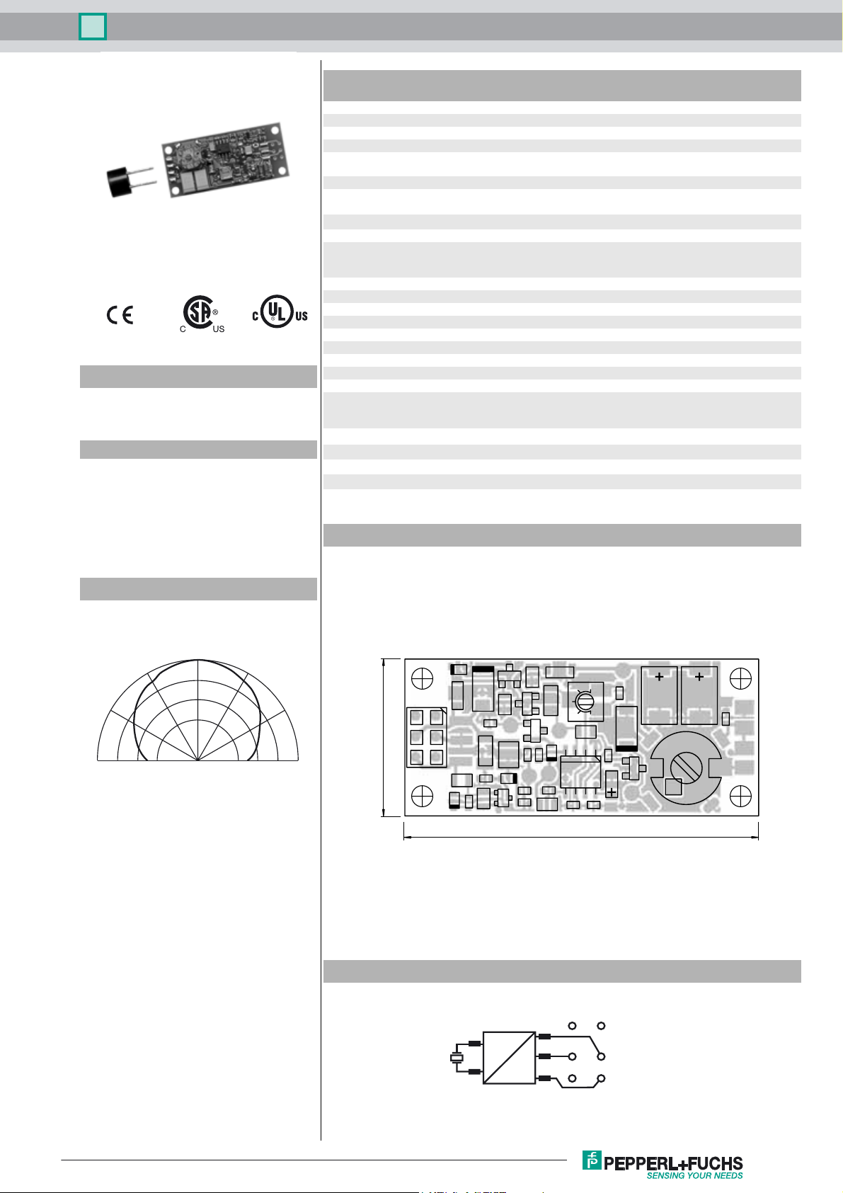
Diagrams
Direction characteristics
0°
30°
60°
90°
30°
-10 0-20-30
Attenuation (dB)
60°
Approvals and certificates
UL approval cULus Listed, General Purpose
CSA approval cCSAus Listed, General Purpose
CCC approval CCC approval / marking not required for products rated
Dimensions
90°
20.2
61
52
43
≤36 V
Q
B1
Q
A1
Q
A2
Q
B2
45
Release date: 2015-02-12 14:45 Date of issue: 2015-02-12 109085_eng.xml
Refer to “General Notes Relating to Pepperl+Fuchs Product Information”.
Electrical Connection
Q
A
Q
B
6
5
4
1
2
+U
-U
B
B
3
1
Ultrasonic sensor, transmitter UBE15M-H1
Function
The emitter is part of a complete system consisting of emitter, receiver and controller
Receiver: UBE15M-F54-H2-V1
Controller: UH3-16E4A-K15-R3
By means of using 2 ultrasonic transducers, aligned to different directions (practically 90° angular difference), the detection range and the angular tolerance can be increased anymore.
Caution:
When aligning both ultrasonic transducers in a parallel way, mutual interference effects can occur. This can cause local amplification respective attenuation of the ultrasonic sound strength.
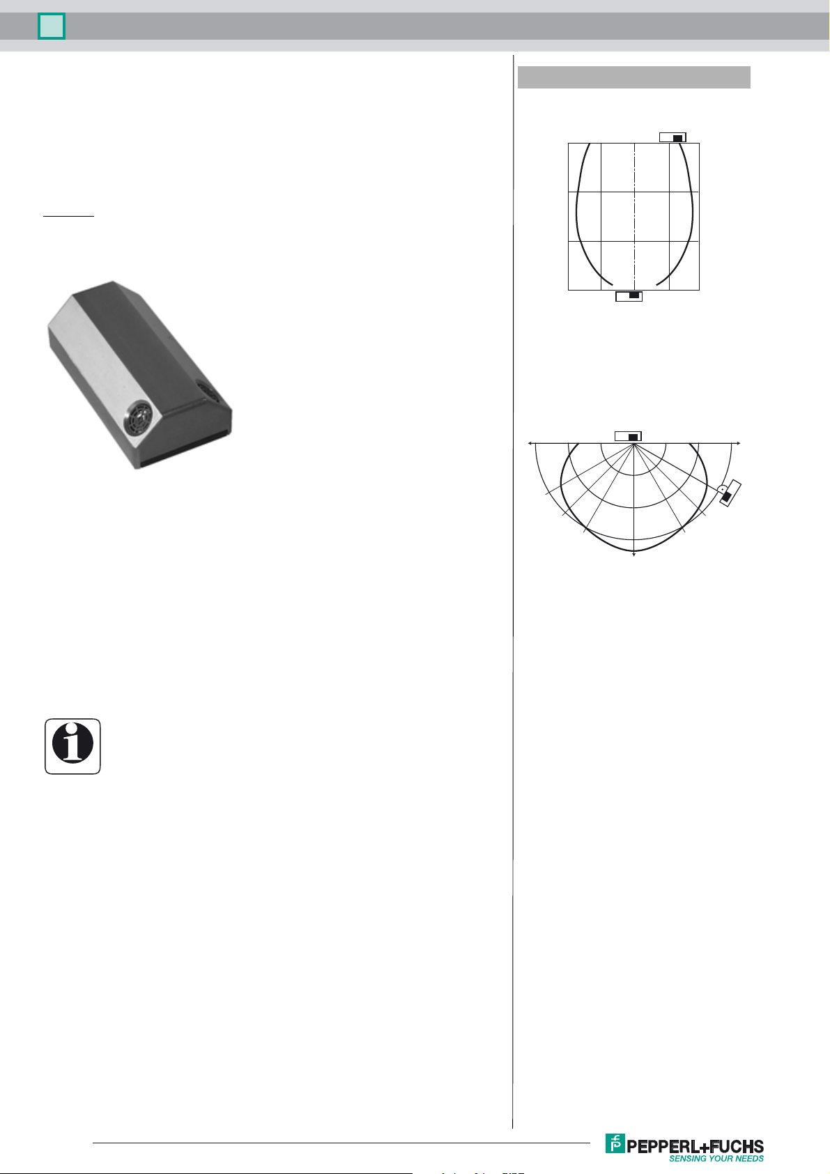
Example of a customized solution with 2 ultrasonic transducers
Additional Information
Characteristic response curve
Distance X [m]
15
10
5
0
10 5 -5 -10
Permissible distance (offset) between the optical axis of the
emitter and receiver.
Offset Y [m]
Characteristic response curve
15 m 10 m 5 m 5 m 10 m 15 m
In real operation, the transmitter and receiver will not be not aligned to each other.
This will reduce the detection range.
The characteristic response curve to the side illustrates examples of the detection
range of the system under the following operating conditions.
- The transmitter and receiver are arranged so they lie parallel opposite each other. The graph shows
the detection range as a function of lateral offset.
- The receiver is arranged vertically downwards, while the emitter is arranged in the direction of the
receiver. The graph shows the detection range as a function of the angle of incidence.
This makes it possible to evaluate the detection range of the system as a function of
the positioning of the transmitter and receiver for conditions that will occur in practical usage.
Cable sockets with built-in indicator LEDs must not be used to
connect this device!
Information
30°
45°
60°
Release date: 2015-02-12 14:45 Date of issue: 2015-02-12 109085_eng.xml
Refer to “General Notes Relating to Pepperl+Fuchs Product Information”.
2
 Loading...