

Ultrasonic sensor UB500-F42-U-V15
Technical data
General specifications
Sensing range 30 ... 500 mm
Adjustment range 50 ... 500 mm
Dead band 0 ... 30 mm
Standard target plate 100 mm x 100 mm
Transducer frequency approx. 390 kHz
Response delay approx. 50 ms
Indicators/operating means
LED green solid green: Power on
Model Number
UB500-F42-U-V15
Single head system
Features
• Analog output 0 ... 10 V
• Extremely small unusable area
• TEACH-IN
• Interference suppression (adjustable divergence of sound cone in
close range)
• Temperature compensation
• Synchronization options
• Mode of operation adjustable
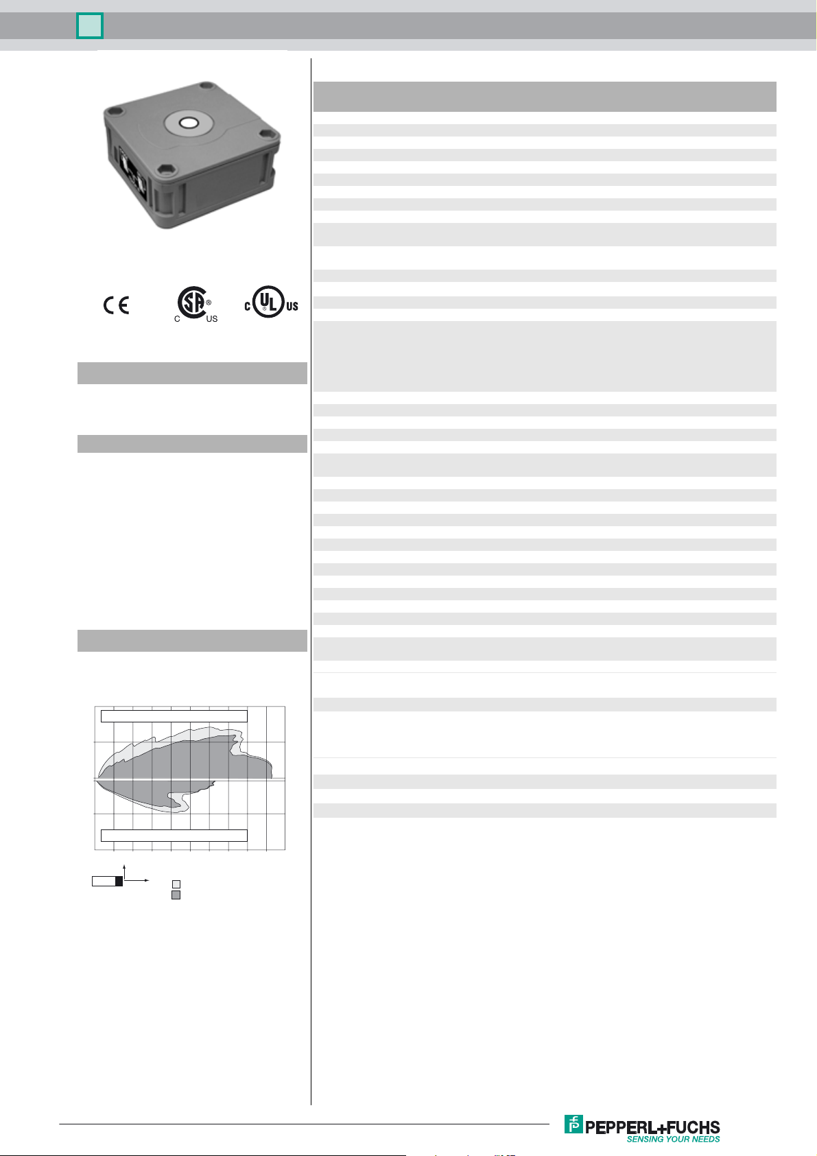
Diagrams
Characteristic response curve
Distance Y [m]
0.2
Flat surface 100 mm x 100 mm
0.1
LED yellow solid: object in evaluation range
LED red normal operation: "fault"
Electrical specifications
Operating voltage U
No-load supply current I
Input/Output
Synchronization bi-directional
Synchronization frequency
Common mode operation ≤ 95 Hz
Multiplex operation ≤ 95/n Hz, n = number of sensors
Output
Output type 1 analog output 0 ... 10 V
Default setting evaluation limit A1: 50 mm , evaluation limit A2: 500 mm ,
Resolution 0.2 mm at max. sensing range
Deviation of the characteristic curve ± 1 % of full-scale value
Repeat accuracy ± 0.1 % of full-scale value
Load impedance > 1 kOhm
Temperature influence ± 1 % of full-scale value
Ambient conditions
Ambient temperature -25 ... 70 °C (-13 ... 158 °F)
Storage temperature -40 ... 85 °C (-40 ... 185 °F)
Mechanical specifications
Connection type Connector M12 x 1 , 5-pin
Degree of protection IP54
Material
Housing ABS
Transducer epoxy resin/hollow glass sphere mixture; foam
Mass 140 g
Compliance with standards and
directives
Standard conformity
Standards EN 60947-5-2:2007 + A1:2012
B
0
flashing: program function
program function: no object detected
17 ... 30 V DC , ripple 10 %
≤ 50 mA
0 level -U
1 level: +4 V...+U
input impedance: > 12 KOhm
synchronization pulse: ≥ 100 µs, synchronization interpulse
period: ≥ 2 ms
wide sound lobe
polyurethane, cover PBT
IEC 60947-5-2:2007 + A1:2012
EN 60947-5-7:2003
IEC 60947-5-7:2003
...+1 V
B
B
SS
0.0
-0.1
Round bar, Ø 25 mm
-0.2
0.0 0.2 0.4 0.6 0.8 1.0
Y
X
wide sonic beam
narrow sonic beam
Release date: 2016-02-26 14:09 Date of issue: 2016-02-26 133979_eng.xml
Refer to “General Notes Relating to Pepperl+Fuchs Product Information”.
Distance X [m]
Approvals and certificates
UL approval cULus Listed, General Purpose
CSA approval cCSAus Listed, General Purpose
CCC approval CCC approval / marking not required for products rated
≤36 V
1
Ultrasonic sensor UB500-F42-U-V15
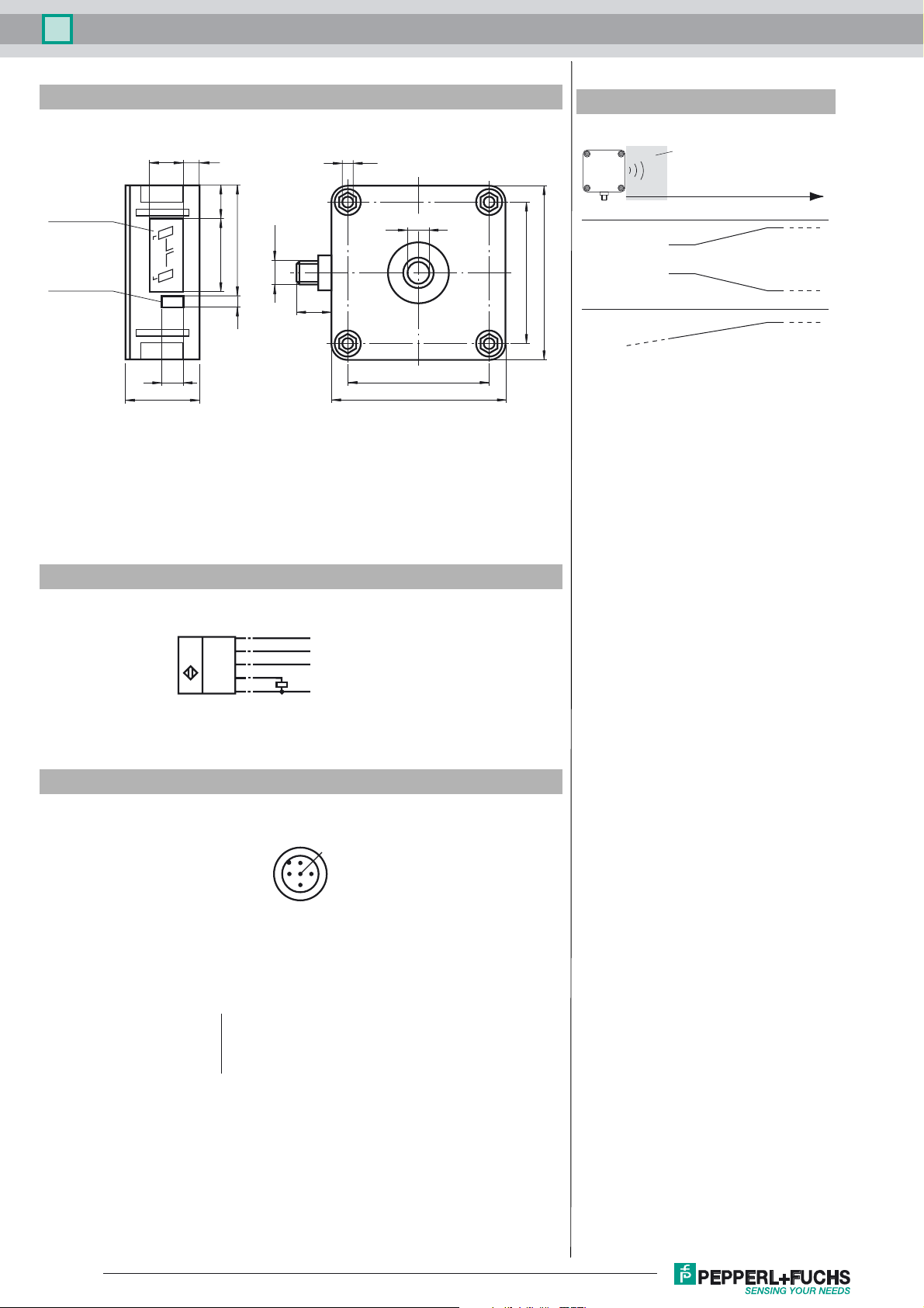
Dimensions
Membrane keys
LED window
Additional Information
Analogue output programmation
7.5
15
15.5
2
A
TEACH IN
1
MODE SET
A
10
34
52.5
34
M12x1
5
16
5.2
10
65
65
80
Rising ramp
80
Falling ramp
Zero line
A1 = 0
Unusable area
A1A1
A1 A2
Object distance
A2
A2
Electrical Connection
Standard symbol/Connections:
(version U)
U
Core colours in accordance with EN 60947-5-2.
Pinout
Wire colors in accordance with EN 60947-5-2
1 BN
2 WH
3 BU
4 BK
5 GY
(BN)
1
(WH)
2
(GY)
5
(BK)
4
(BU)
3
2
+ U
B
Teaching input
Sync.
Analog output
- U
B
1
5
4
3
(brown)
(white)
(blue)
(black)
(gray)
Release date: 2016-02-26 14:09 Date of issue: 2016-02-26 133979_eng.xml
Refer to “General Notes Relating to Pepperl+Fuchs Product Information”.
2

Ultrasonic sensor UB500-F42-U-V15
Accessories
MH 04-3505
Mounting aid for FP and F42 sensors
MHW 11
Mounting brackets for sensors
DA5-IU-2K-V
Process control and indication equipment
V15-G-2M-PVC
Female cordset, M12, 5-pin, PVC cable
Functional Description
The sensor may be completely parameterised via two keys on the side panel of the housing. As a special feature provided by
this sensor, the ultrasound beam width may be adapted to the environmental conditions at the place of operation of the sensor.
Specifying the evaluation limits:
The evaluation limits determine the characteristic line and the working range of the analog output.
Specifying the A1 evaluation limit by pressing the A1 key
Holding down the A1key > 2
seconds
Position the target object at
the desired distance
Briefly pressing the A1 key The sensor terminates the specification of the A1 eval-
The sensor switches to learn mode and the user may
specify the A1 evaluation limit
The yellow LED of the sensor flashes fast to indicate
that the target object is recognised. The red LED flashes if the object is not recognised.
uation limit and saves it as a non-volatile value. The
specified value is invalid if the object is uncertain (i.e.
the red LED lights up at irregular intervals). The learn
mode is exited.
The A2 evaluation limit is specified via the A2 key, analogous to the description above.
Alternatively, the evaluation limits may also be specified electrically via the learn input. To specify the A1 evaluation limit, the
learn input must be connected to
-U
; to specify the A2 evaluation limit, it must be connected to +UB. Specified values are saved upon the disconnection from
B
the learn input.
Evaluation limits may only be specified within the first 5 minutes after Power on. To modify the evaluation limits later, the user
may specify the desired values only after a new Power On.
Proceed as follows to parameterise the output function and the ultrasound beam width:
Press the A1 key during Power on and hold down the key for another second to ensure that the sensor starts the two-step parameterisation of the operating modes.
Step 1, parameterisation of the output function
The output function parameterised last is displayed. All output functions available may be selected via consecutive, brief strokes
of the A2 key. These strokes are visualised via short flashes of the green LED.
Operating mode Flash sequence of the green LED A2 key
Rising edge
Falling edge
Zero point straight
line
pause
pause
pause
The "Zero point straight line“ setting fixedly specifies the A1 evaluation limit to 0 (see specification of the evaluation limits). The
A2 evaluation limit determines the steepness of the output characteristic line.
Hold down the A1 key for 2 seconds to save the selected output mode, complete the parameterisation and ensure that the sensor returns to normal mode. If you briefly press the A1 key, Step 2 is entered (parameterisation of the ultrasound beam width).
Step 2, parameterisation of the ultrasound beam width
Via Step 2, the ultrasound beam width may be adapted to the requirements of the corresponding application.
The beam width parameterised last is displayed first. Available beam width settings may be selected via consecutive, brief
strokes of the A2 key. These strokes are visualised via the flash sequence of the red LED.
Release date: 2016-02-26 14:09 Date of issue: 2016-02-26 133979_eng.xml
Refer to “General Notes Relating to Pepperl+Fuchs Product Information”.
3

Ultrasonic sensor UB500-F42-U-V15
Beam width Flash sequence of the red LED A2 key
Small beam
Medium beam
Large beam
pause
pause
pause
Hold down the A1 key for 2 seconds to save the selected beam shape, terminate the parameterisation and ensure that the sensor returns to normal mode. Briefly press the A1 key to return to Step 1 (parameterisation of the output function).
If the parameterisation mode is not terminated within 5 minutes (hold down the A1 key for 2 seconds), the sensor aborts this
mode without modifying the settings.
Synchronisation
The sensor provides a synchronisation port to suppress mutual influencing. If this port has not been connected, the sensor
works at an internally generated cycle rate. Several sensors may be synchronised via the following options.
External synchronisation:
The sensor may be synchronised via the external application of a square wave voltage. A synchronisation pulse on the synchronisation input initiates a measuring cycle. The pulse width must be greater than 100 µs. The measuring cycle is started with
the falling edge. A low level > 1 s or an open synchronisation input initiate the transition to normal sensor mode. A high level on
the synchronisation input deactivates the sensor.
Two modes are possible:
- Several sensors are controlled via the same synchronisation signal. The sensors work in common mode.
- The synchronisation pulses are forwarded at cyclic intervals to respectively one single sensor. The sensors work in multiplex mode.
Self-synchronisation:
The synchronisation ports of up to 5 sensors suitable for self-synchronisation are connected to each other. These sensors work
in multiplex mode after Power on. The On delay increases depending on the number of sensors to be synchronised. While the
learn mode is active, no synchronisation is possible (and vice-versa). To specify the switching points, the sensors must be operated in non-synchronised mode.
Note:
If the synchronisation option is not used, the synchronisation input must be connected to ground (0V) or the sensor must be
operated with a (4-pole) V1 connecting cable.
Release date: 2016-02-26 14:09 Date of issue: 2016-02-26 133979_eng.xml
Refer to “General Notes Relating to Pepperl+Fuchs Product Information”.
4
 Loading...