

Page 1
MANUAL
OPC / OPD / OPE
Optical Print Inspector
FACTORY AUTOM ATION
Page 2

OPC / OPD / OPE
With regar d to the supply of products, the current issue of the following document is applicable: The
General Terms of Delivery for Products and Se rvices of the Elec trical Industry, published by the
Central Asso ciation of th e Electrical In dustry (Zentralverba nd Elektrote chnik u nd Elektroindustrie
(ZVEI) e.V.) in its most recent version as well as the supplem entary clause: "Expanded reservation
of proprietorship"
Page 3

OPC / OPD / OPE
Contents
1 Introduction......................................................................... 5
2 Declaration of Conformity ................................................. 6
3 Safety................................................................................... 7
3.1 Symbols Used............................................................ ...................................7
3.2 Intended Use ........ ..................................................... .......... .........................7
4 Product Description ........................................................... 8
4.1 Use and Application....... .......... ............................................................... ......8
4.2 Indicators and Operating C ontrols .......... ......... .............................................9
4.3 Interfaces and Connections .................................................................... .... 12
4.4 Scope of Delivery ...... ...................................................... .......... ..................16
4.5 Accesso ries ................... .......... ...................................................... ......... .... 16
4.5.1 Power Supply ........................... .............................................................. 16
4.5.2 Network Cable.......................... .......... .................................................... 17
4.5.3 RS-232 Interface .. .......... ...................................................... .......... ........17
4.5.4 VGA Output ................................... .......... ...............................................1 7
5 Installation......................................................................... 18
5.1 Preparation ...... ......... ...................................................... .......... ..................18
5.2 Mounting the Device ............................... ......... ...........................................18
5.3 Setting up the Power Supply ...................................... .......... ....................... 20
5.4 Setting Up a Network Connection .................... ...........................................21
5.5 Storage and Transport................................................ .......... ....................... 23
6 Commissioning................................................................. 24
6.1 Connecting the Stationary Read Device...................................................... 24
7 Vision Configurator Software.......................................... 25
7.1 Application Window Structure ......................................... .......... ..................26
7.2 Menu Bar .................. .......... ...................................................... .......... ........27
7.2.1 File Menu ................................. .............................................................. 27
7.2.2 View Menu ............................... .......... ....................................................28
7.2.3 Sensor Menu .................................................... .......... ............................28
7.2.4 Image Menu ............................. .............................................................. 29
7.2.5 Administration Menu ................................................... .......... ..................30
7.2.6 Help Menu ...................... .......... .............................................................. 30
2015-0 7
3
Page 4

OPC / OPD / OPE
Contents
7.3 Configuration Window ............................... ................................................. 31
7.3.1 System Tab ............. .......... ................................................................ ..... 31
7.3.2 Camera Tab ............................................... ......... ................................... 34
7.3.3 Image Filter Tab ............................... ...................................................... 34
7.3.4 Trigger Mode s Tab ........................................................ .......... ............... 36
7.3.5 Window Tab .......................................... ................................................. 39
7.4 Toolbar ........................ .......... ................................................................ ..... 46
7.5 Sensor Data ................................................... ......... ................................... 47
7.6 Sensor Output ............. .......... ...................................................... .......... ..... 47
7.7 Image Display ................................. .......... ................................................. 48
8 Operation .......................................................................... 50
8.1 Reading a 1- D/2-D Code...................... ...................................................... 50
8.2 Reading Overlong 1-D Codes ................................................ .......... .......... 5 1
8.3 Comparing a 1-D/2-D Code .................................... ................................... 52
8.4 Comparing a Logo ....... ................................................................ ............... 53
8.5 Checking the Presence of Materials with a Changeable Texture ................ 54
9 Maintenance and Repair.................................................. 56
9.1 Maintenance ...................................................... ........................................ 56
9.2 Repair ............................................. ........................................................... 56
10 Troubleshooting ............................................................... 57
10.1 What to Do in the Event of an Error ........................................ .......... .......... 57
11 Appendix........................................................................... 58
11.1 Network Interface ............................ .......... ................................................. 58
11.2 Software Interface ....... ...................................................... .......... ............... 58
11.2.1 Configuratio n Ove rview .............. ...................................................... ..... 66
11.2.2 Result Overview....................................................... .......... .................... 72
4
2015-0 7
Page 5
OPC / OPD / OPE
Introduction
1 Introduction
Informative Symbols
Note!
This symbo l brings important information to your attention.
Action
This symbo l indicates a pa ragraph with instructions.
Contact
If you have any q uestions about the device, its functions, or acces sories, please
contact us at:
Pepperl+Fuchs GmbH
Lilienthalstraße 200
68307 Mannheim
Telephone: +49 62 1 776 -4411
Fax: + 49 621 776-2 74411
E-Mail: [email protected]
2015-0 7
5
Page 6

OPC / OPD / OPE
ISO9001
Declaration of Conformity
2 Declaration of Conformity
This product was developed and manufactured unde r obser vance of the
applica ble European standards and guidelines.
Note!
A Declaration o f Conformity can be reques ted from the manufacturer.
The product m anufacturer, Pepperl+Fuchs GmbH, D-68 307 Mannhe im, has a
certified quality assurance system that conforms to ISO 90 01.
6
2015-0 7
Page 7
OPC / OPD / OPE
Safety
3 Safety
3.1 Symbols Used
This document contains information that you must observe for you r own p ersonal
safety and to prevent property damage. Warning mes sages are shown in
descending order according to the risk level, as follows:
Safety- Relevant Symbols
Danger!
This symbo l indicates an immine nt dang er.
Non-observance will result in pe rsonal injury or death.
Warning!
This symbo l indicates a po ssible fa ult or danger.
Non-observance may caus e personal injury or serious pro perty dama ge.
Caution!
This symbo l indicates a po ssible fa ult.
Non-observance could interrupt the device and any co nnected system s and
plants, or resu lt in th eir complete failure.
3.2 Intended Use
The stationary read devices OPC-*, OPD-*, and OPE-* are used to decode 1-D
and 2 -D codes.
The device is only approved for app ropriate and intended use. Ignoring these
instructions will void any warranty and ab solve the man ufacturer from a ny liab ility.
Protection of the pe rsonnel and the plant is not ensured if the device is not being
used accord ing to its intended use.
2015-0 7
7
Page 8
OPC / OPD / OPE
Product Description
4 Product Description
4.1 Use and Application
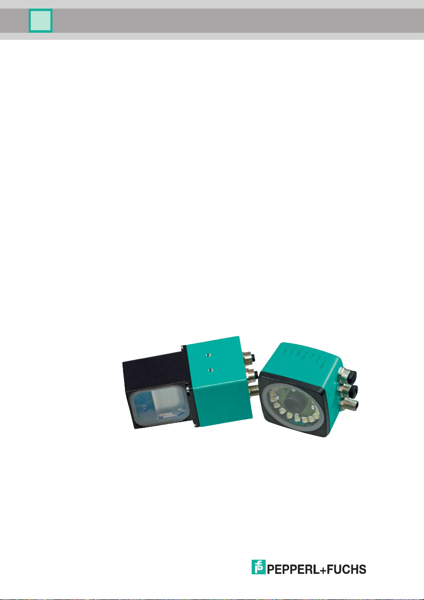
The optical print inspector is available in three versions and reads both 1- D and 2D codes. For high speed, great depth of focu s, long barcodes, or detection tasks;
with the optical print inspector you always have the right vision sen sor at ha nd.
Use the innovative image proces sing technology from Pepperl+Fuchs for your
application.
You can configure the stationar y readers quickly and easily over a standa rd
Ethernet interface, using the software provided. The reader has an integrat ed fault
pattern memor y.
Highlights:
■ Reads 1-D and 2-D codes at extremely high speeds of up to 10 m/s at
30 readings/s
■ Detects long barcodes of up to 200 mm long using multiple imag e capture
■ Reads up to four differen t codes at the same time
■ Logo comparison
■ Position of the reading field can be adjusted flexibly via rotary encoder input
(OPC and OPD)
■ Captures code s and logos at different distanc es and of different sizes with
one setting
■ Side lighting for reliable reading with highly reflective surfaces
2015-0 7
8
Page 9
OPC / OPD / OPE
1 2 3 4 5 6
7
Product Description
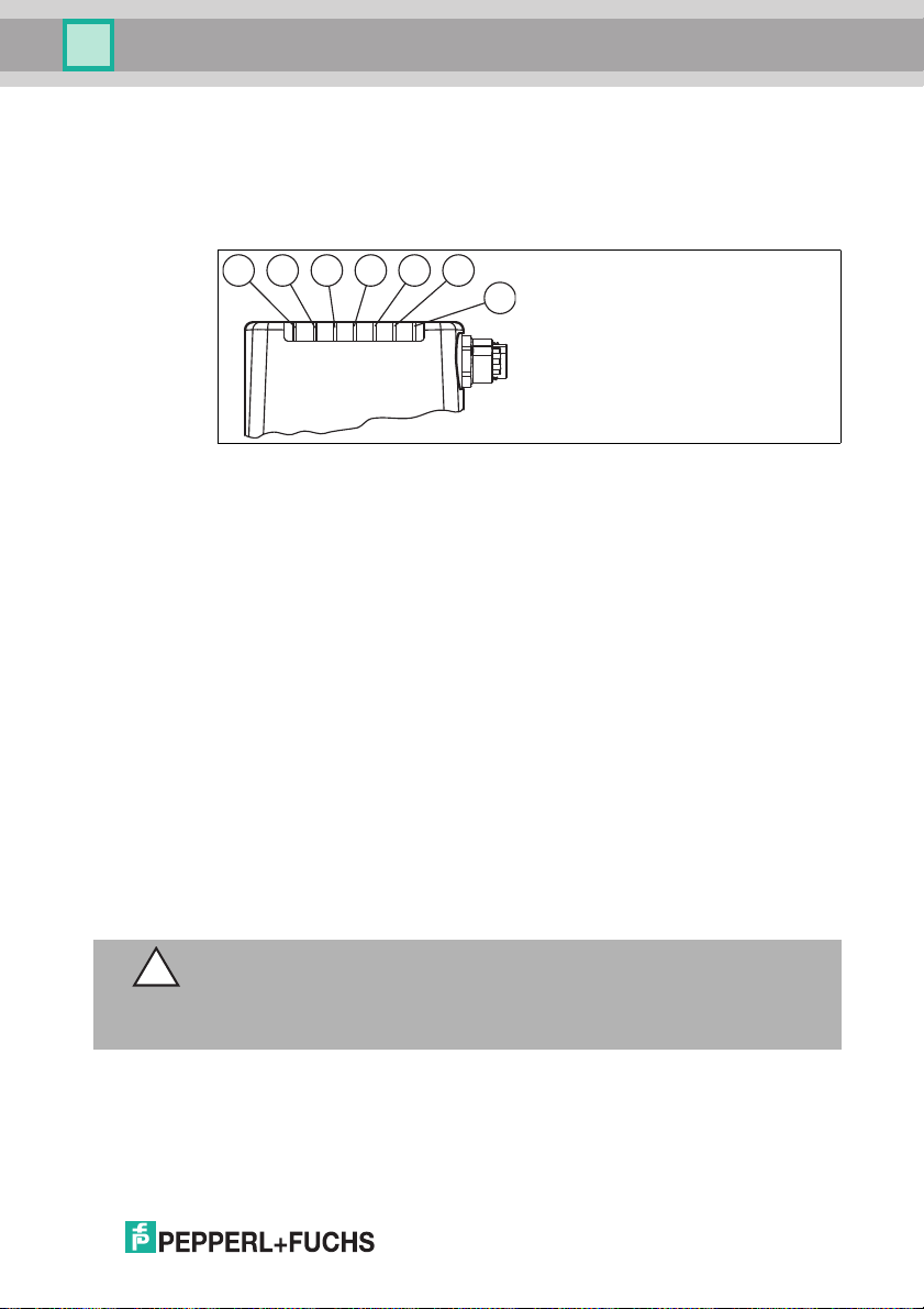
4.2 Indicators and Operating Controls
OPC reader and OPD reader
The illumination unit has 7 LED indicators that provide information on t he various
device statuses.
Figure 4.1 Indicators and Operating Control s
1. DIAG 2
Yellow L ED. Generates different flashing sequences to signal diag nostic
messa ges.
2. DIAG 1
Yellow L ED. Generates different flashing sequences to signal diag nostic
messa ges.
3. Power (PW R)
Lights up green whe n the sensor is ready for operation.
4. Ready (READY)
Lights up yellow when the sensor is rea dy.
5. Reading process triggered (BAD)
Lights up yellow if the read ing was unsuccessful.
6. Reading process triggered (GOOD)
Lights up yellow if the read ing was successful.
7. Trigger senso r (TRG)
Lights up yellow when a c onnected trigg er sensor is activated.
Caution!
Software update
The READY LED flashes while the senso r is being programmed. During this time,
the sensor must not be switched off.
2015-0 7
9
Page 10
OPC / OPD / OPE
Product Description
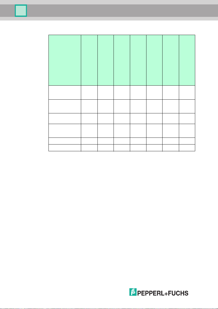
Definit ion of the LEDs an d Outputs for Individual Statuses
GOOD LED
Good read ON OFF OFF 80 ON OFF OFF
Bad read OFF ON OFF 81 OFF ON OFF
Good read and
match code OK
Good read and
match code not
OK
Bad read OFF ON ON 81 OFF ON OF F
Decoder timeout OFF ON 84 OFF ON OFF
ON OFF ON 82 ON OFF ON
OFF ON ON 83 OFF ON OF F
BAD LED
Match code operating mode
Status
Good output
Bad output
(Not
used)
(Not
used)
Match code output
10
2015-0 7
Page 11
OPC / OPD / OPE
3
4
5
6
2
1
7
LAN
TRG
Fail
Status
PWR
LAN
RS 232
24VDC + IO
VGA
Match
Good
Product Description
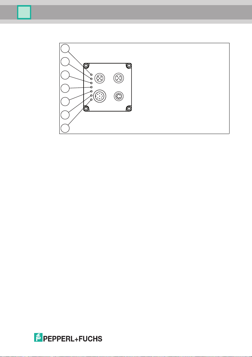
OPE reader
1. Network (LAN ):
Lights up yellow as soon as a physical connec tion is established.
2. Trigger (TRG) :
Lights up yellow when a co nnected trigg er sensor is a ctivated.
3. Good (Good):
Lights up green if the reading is s uccess ful.
4. Error (Fail):
Lights up red if the r eadin g is uns uccess ful.
5. Result (Match):
Flashes green if the match code matches the read c ode.
Flashes red if the match code does not match the read code.
6. Status (Status):
Briefly flashes yellow when the device is switched on.
Flashes yellow during a firmware update.
Lights up green whe n the device is read y.
Lights up red in the event of a dev ice error.
7. Power (PW R):
Lights up green whe n the sensor is connected to a power supply.
2015-0 7
11
Page 12
OPC / OPD / OPE
1
2
3
1
4
6
7
8
53
2
Product Description
4.3 Interfaces and Connections
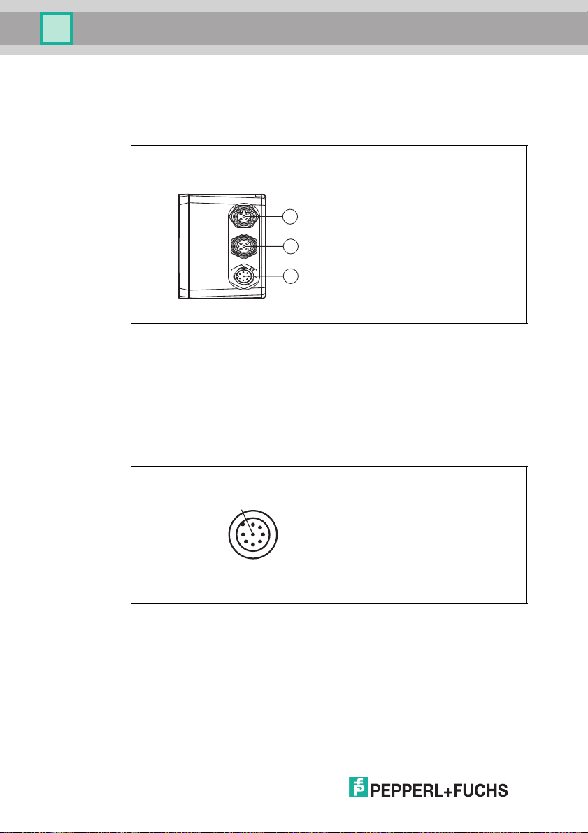
OPC reader and OPD reader
The device includes the following connections:
Figure 4.2 Device Conne ctions
1. Network ( 4-pin M12 socket)
2. Input IO (5 -pin M12 socket)
3. Power sup ply, inputs, and outputs (8-pin M12 plug)
Power Supply
There is an 8-pin M12 plug on the side of the ho using for con necting the power
supply, and the inputs and outputs. The following d iagram shows the pinning:
12
Figure 4.3 Connection layout for oper ating voltage, and inputs and outputs
1. Trigg er IN
2. + UB
3. OUT Good
4. OUT Bad
5. IN 1
6. OUT 1
7. GND
8. OUT match code
2015-0 7
Page 13
OPC / OPD / OPE
1
5
3
2
4
1
3
4
2
Product Description
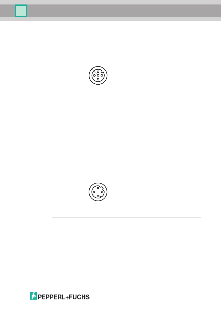
RS-232 Interface
There is a 5-pin M12 soc ket on the side of the sensor housing. The following
diagram shows the pinnin g:
Figure 4.4 RS-232 input connection layout
1. + UB
2. TX RS-232
3. GND
4. RX RS-232
5. NC
Network
There is a 4-pin M12 soc ket on the side of the housing for connecting to the
networ k. The following diagr am shows the pinning:
Figure 4.5 Network connec tion layout
1. TX+ Ethernet
2. RX+ Ethernet
3. TX- Ethernet
4. RX- Ethernet
2015-0 7
13
Page 14
OPC / OPD / OPE
3
4
2
1
LAN
TRG
Fail
Status
PWR
LAN
RS 232
24VDC + IO
VGA
Match
Good
1
4
6
7
8
53
2
Product Description
OPE reader
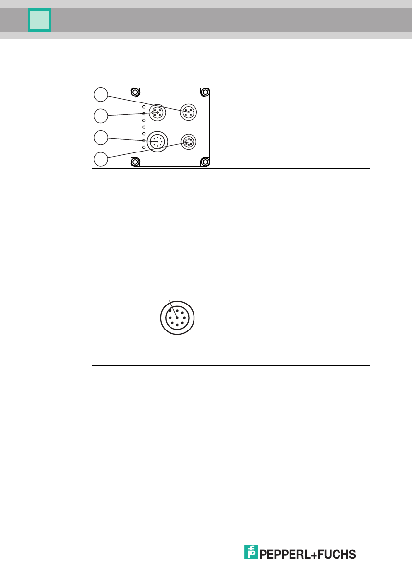
The device includes the following connections:
1. RS-232 interface (5-pin M12 s ocket)
2. Network ( 4-pin M12 socket)
3. Power sup ply, inputs, and outputs (8-pin M12 plug)
4. VG A output (7-pin M12 socket)
Power Supply
There is an 8-pin M12 plug on the back of the sensor housing to co nnect the
power supply, and to the inputs and outputs. The following d iagram shows the
pinning:
Figure 4.6 Connection layout for oper ating voltage, and inputs and outputs
1. IN T RG / OUT 1
2. +U B
3. OUT Good / IN 1
4. OUT Fail / IN 2
5. IN 3
6. IN 4 / OUT 2
7. GND
8. OUT Match
Pin 1, pin 3, pin 4, and pin 6 have dual assignments, but these dua l assignments
are not currently supported by the software: OUT 1, IN 1, IN 2, IN 3, IN 4 are
intended for future app lications.
14
2015-0 7
Page 15
OPC / OPD / OPE
1
3
4
2
1
5
3
2
4
Product Description
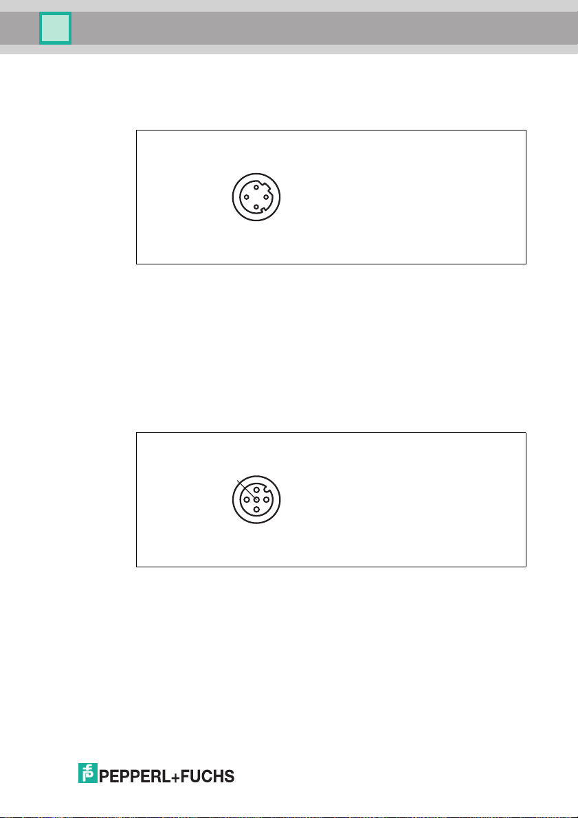
Network
There is a 4-pin M12 soc ket on the back of th e sensor hous ing to connec t to the
networ k. The following diagr am shows the pinning:
Figure 4.7 Network connec tion layout
1. TX+ Ethernet
2. RX+ Ethernet
3. TX- Ethernet
4. RX- Ethernet
RS-232 Interface
There is a 5-pin M12 soc ket on th e back o f the se nsor housing for connecting the
RS-232 interface or external lighting. When using as the RS-232 interface, do not
conn ect any cables to pin 1 or p in 5. The following diagram s hows the pinning:
Figure 4.8 RS-232 connec tion layout
1. +UB
2. TX RS-232
3. GND
4. RX RS-232
5. IN 5 / OUT 3
2015-0 7
15
Page 16
OPC / OPD / OPE
1
3
4
5
6
7
2
L
Product Description
VGA Output
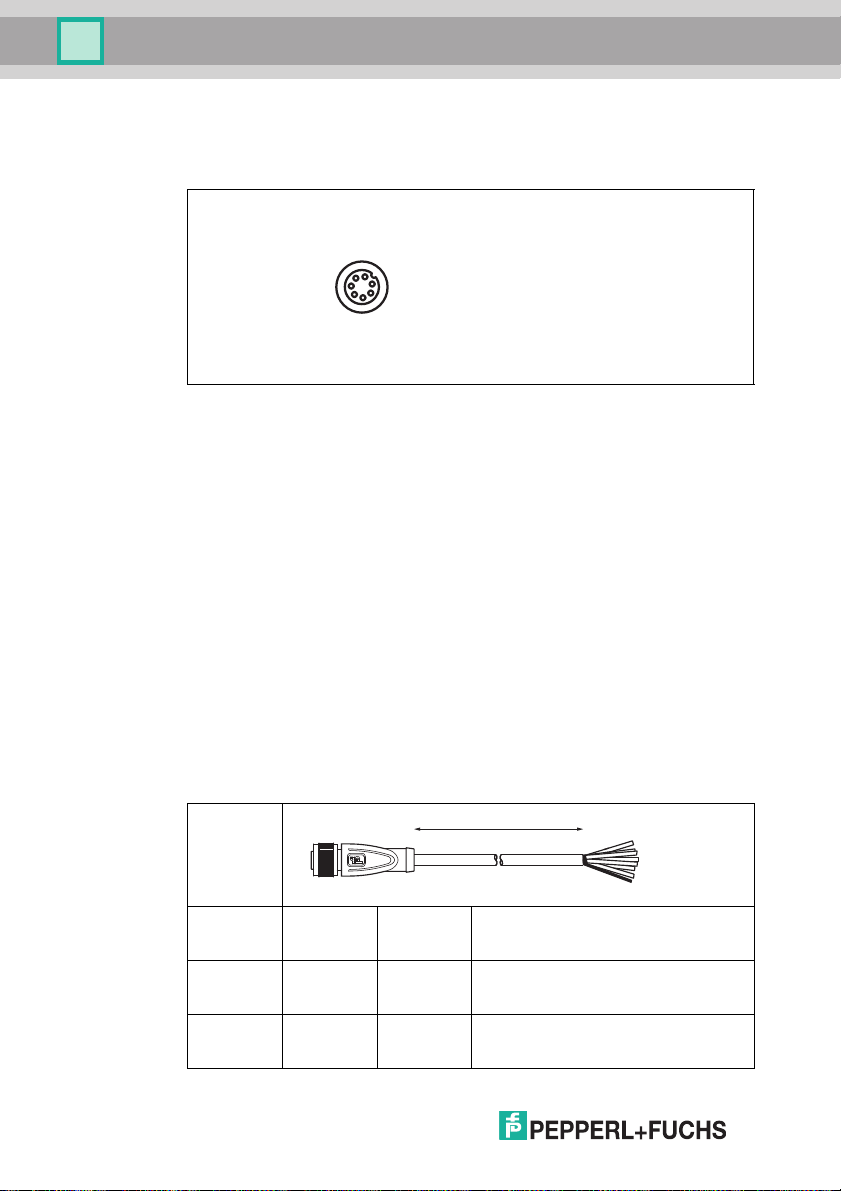
There is a 7-pin M9 socket on the back o f the se nsor housing to connect the VGA
plug. The following diagram shows the pinning:
1. OUT VSY NC
2. GND
3. OUT R
4. OUT G
5. GND
6. OUT B
7. OUT HSYNC
4.4 Scope of Delivery
■ Optical Print Inspector
■ Quick start guide
4.5 Accessories
Various accessories are available.
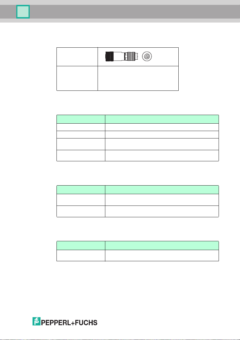
4.5.1 Power Supply
Use the following doub le-ended cordset to connect the p ower supply, inputs, and
outputs to the sensor.
Female field connec tor
Model
numb er
16
V19-G-2M PUR-ABG
V19-G-5M PUR-ABG
V19-G10M-PU RABG
8-pin M12
socket,
straig ht
8-pin M12
socket,
straig ht
8-pin M12
socket,
straig ht
L = 2 m Open cable end with multistranded
L = 5 m Open cable end with multistranded
L = 10 m Open cable end with multistranded
conductors
conductors
conductors
2015-0 7
Page 17
OPC / OPD / OPE
Product Description
Other lengths on reques t.
Field-attachable M12 socket
Model num ber
V19-G-ABG-PG9 ■ 8-pin M12 socket, straight
4.5.2 Network Cable
The sensor is connected to the network using an M1 2 plug.
Desi gnation Description
V45-G RJ45 network p lug, field attachable
V1S -G M12 plug, 4-pin, field attachable
V1S D-G-2M -PURABG-V45X-G
V1S D-G-2M -PURABG-V45-G
4.5.3 RS-2 32 Interface
The sensor 's RS-232 interface is connected via an M12 plu g.
Desi gnation Description
V15S -G-5M-PUR-A BG Male single-ended cordset, M12, 5-pin, PUR c able, shielded
V15S -G-5M-PUR-A BGSU BD9
4.5.4 VGA Output
The sensor is connected to a monitor using a n M9 p lug.
■ Sc rew terminals for max. 0.75 mm
cable gland
■ Cable diam eter: 5 mm ... 8 mm
Double-ended cordset, RJ45 network plug with M12 plug,
crossed, 4-pin
Double-ended cordset, RJ45 network plug with M12 plug, 4pin
cap nut
Connection cab le, M12 plug, 5 -pin, 9 -pin to D-Sub housi ng
2
PG9
Desi gnation Description
ODZ-MAC-CAB -VIDEO Video connec tion cable, round plug, 7-pin on D-Sub socket,
2015-0 7
15-pin VGA, length: 2 m
17
Page 18
OPC / OPD / OPE
Installation
5 Installation
5.1 Preparation
Unpacking the unit
1. Check that all package contents are prese nt and undam aged.
If anything is d amaged, in form the shipp er and contact the sup plier.
2. Check that all items are present and co rrect based o n your order and the
shipping documents.
If you have any question s, please contact Pepper l+Fuchs .
3. Keep the original packing material in case you nee d to store or ship the unit at
a later time.
5.2 Mounting the Device
Note!
Mounting an optic al device
■ Do not a im the senso r at the sun.
■ Protect the sensor from direct long-term expo sure to sun.
■ Prevent co ndensation from forming by no t exposing the sensor to any
major fluctuations in temperature.
■ Do not ex pose the sens or to the effects of any ag gressive chemicals.
■ Keep the lenses a nd reflector of the d evice clean. Clean with a so ft cloth,
using standard commercial glass cleaner if nece ssary.
We recommend to clea n the optical surface and to check screw fittings and
electric al conn ections at regular intervals.
18
Note!
Preventing reflection and glare
Reflection and glare from reflective surfaces can impair the captured image and
therefore lead to incorrect read ings. To prevent reflection and glare, install the
stationar y reading device at a s light angle.
The surface must be level to prevent the housing from becoming d istorted when
the fittings are tightened. After mounting the senso r, ensure that the re is still
enough space to co nnect the con nection cable to the sensor.
2015-0 7
Page 19
OPC / OPD / OPE
12.5
54
2020
M12
M12
M6 x 9 (4x)
25
21.75
25
12
70 13.8
70
80
Installation
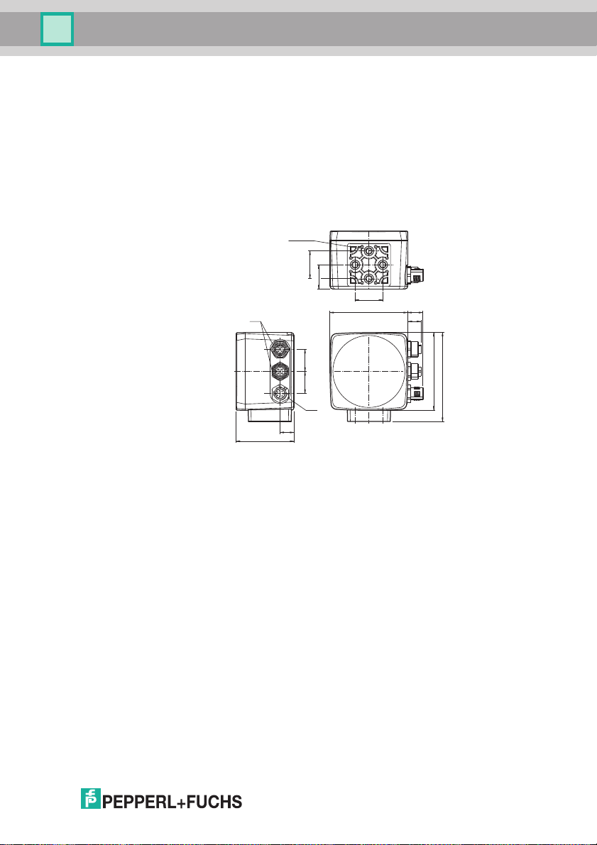
OPC and OPD mounting
The reader has four symmetrically positioned M6 threads on the base of the
housing to allow e asy mounting o f the r eader in your plant.
The read distance differs ac cording to the reader. You can find the correct read
distanc e in the tech nical data for the reader to be installed.
The following illustration shows all the relevant hous ing dim ensions in m m:
2015-0 7
19
Page 20
OPC / OPD / OPE
Reading distance
11
60
60 65
M5
20 6
11
Code
52.7
20 ±0.1
72.5
Installation
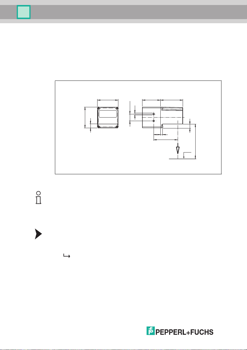
OPE mounting
The device has two M5 threads positioned on the base of the housin g to allow
easy mo unting of the reader in your plant.
The read distanc e diffe rs according to the re ader. You can find the correct read
distance in the technical data for the reader to be installed.
The following illustration shows all the relevant housing dimensions in mm:
Figure 5.1 Dimensions o f the angle housing
Note!
Connection to grou nd
When installing the device, ens ure that it is has a gr ound connection.
5.3 Setting up the Power Supply
Connecting the Supply Voltage
1. Insert the 8 -pin M12 socket into the plug p rovided on the side of the housing.
2. Screw the c ap nut onto the connector as far as it will go.
This en sures that the power c able cannot be inad vertently pulled out.
20
2015-0 7
Page 21
OPC / OPD / OPE
Installation
5.4 Setting Up a Network Connection
Note!
Network Cab ling
Use a crossover network cable to conn ect the sensor directly to a computer. If you
are op erating the se nsor within a network, use a twisted-pair network cable.
Connecting the Network Cable
1. Use a network cable that has an RJ45 network connec tor on one side and a 4pin M12 plug on the other. Inse rt the M12 plug into the LAN socket on the sensor.
2. The sensor is supplied with the IP address 192.168.002.003. To connect it
to a PC, set up an IP address o n the PC where the first three segments are
identical to the sensor's IP addres s, e.g., 192.168.002.090. The last
segment mu st be different from the one in the sensor's IP address.
Note!
Documenting the Network Co nfigur ation
If you change the senso r's IP ad dress, make a note of this change so that you can
conn ect the senso r to a PC.
Reset ting the IP Address
If you do not know the IP address of the sensor, you can reset the IP add ress to
the factory default setting.
1. Connect the sensor to the power sup ply.
The sensor po wers up.
2. Wait until the LEDs flash.
3. Hold down buttons 1 and 2 on the back of the sens or simultaneously for
approx. two seconds.
The LED flash seque nce changes.
The sensor p owers up again and now use s the fa ctory default IP address.
2015-0 7
21
Page 22
OPC / OPD / OPE
Installation
Setting the IP Address of the PC (Windows 7)
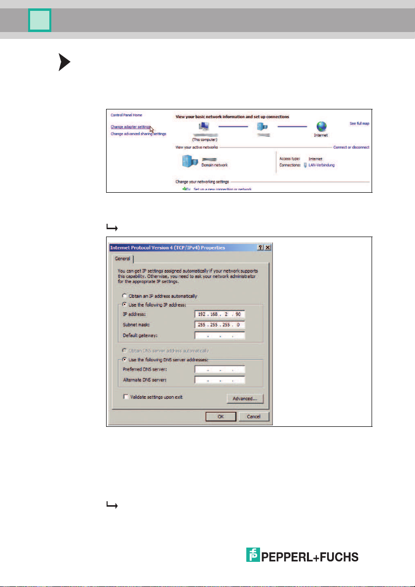
1. Select Start > Control Panel.
2. Select Network and Sharing Center.
3. Select Chang e Adapter Settings .
4. Right-click the required conne ction and select Properties.
5. Select Interne t Protocol Version 4 (TCP/IPv4) a nd click Properties.
The Properties window for the TCP/IP protocol o pens.
22
6. Select Use the Following IP Address.
7. Enter an IP addres s wher e the f irst three segm ents are identical to those of
the IP address for the sensor, e.g., 192.168.002.090 . The la st segment
must be different to the IP address of the sensor.
8. Enter 255.255.255.0 as the subnet mask.
9. Click OK and Close.
This c ompletes the network configuration and the sensor can b e used.
2015-0 7
Page 23

OPC / OPD / OPE
Installation
5.5 Storage and transport
For st orage and transport purposes, package the unit using shock proof
pac kaging material and protect it against moisture. Th e best method of protection
is to package the unit us ing the origin al packaging. Further more, ensure that the
ambient condition s are within allowable range.
2015-0 7
23
Page 24

OPC / OPD / OPE
Commission ing
6 Commissioning
6.1 Connecting the Stationary Read Device
The reader can be controlled via the Vision Configurator software. You have the
ability to make adjustments on the stationary reader directly using the Vision
Configurator software.
Alignin g the Stationary Reader
Use the image display in the Vision Configurator software to optim ally align the
reader.
1. Power the reade r via the 24 VDC + IO socket on the device.
2. Align the device such that the contrast between the code and the background
in the image display is as sharp as possible.
This sets the ideal readin g distance between th e stationary reader and the
code to be read.
24
2015-0 7
Page 25
OPC / OPD / OPE
Vision Configurator Software
7 Vision Configurator Software
The sensor is comm issioned and operated using the Vision Configurator
software.
The Vision Configurator so ftware makes it easy to operate the sensor with its userfriendly interface. Standard functions include making c onnections to the sensor,
specify ing the operating parameters, saving d ata sets, and displaying data a nd
error diagnostics.
Note!
The following user roles are p redefined with d ifferent autho rizations in the Vision
Configurator.
User Rights and Password
User rights Desc ription Password
Default View all information
User View all information
Admin
PFAdmin
Establish ing a Network Connection
To establish a network c onnection with the sensor, proceed as follows:
1. Supply the senso r with power.
2. Start th e Vision Con figurator software.
3. Select the connected sensor.
4. Check that the c orrect IP addre ss has been entered.
5. Enter your user na me and passwor d.
A connection to the sensor is established .
Note!
Documenting the Network Configuration
The sensor communicates with the connected m achine control system u sing the
TCP/IP protocol. To ensure pro per co mmun ication, you mus t record all the
changes made to the netwo rk configuration.
Create users at same or lower level
Senso r con figuration
Create users at same or lower level
View all information
Senso r con figuration
Create and delete users
A password is not requi red
User
Request the admin p assword
from Pepperl+Fuchs
An up-to-date description of the Vision Configurat or software can b e found at
http://www.pepperl-fuchs.com.
2015-0 7
25
Page 26
OPC / OPD / OPE
1
2
3
4
56
7
8
10
11
9
Vision Configurator Software
7.1 Application Window Structure
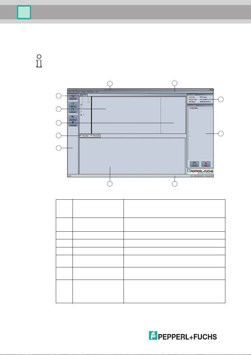
The application screen opens after you log in.
Note!
The ind ividual functions depend o n the type of sensor connected and the current
authorization level, so they are no t always all visible.
The software is d esigned to be similar to most Windows ap plications.
1 Title ba r ■ Shows the IP address, the software name, and the
2 Menu bar ■ Dis plays all the menus in the program
3 Sensor data screen ■ Dis plays data for the connected sensor
4 Sensor output screen ■ Shows the log display
5 Status bar ■ Dis plays status information about the app lication
6 Configuration w indow ■ Contains the sensor-spe cific parameter s that you
7 Toolbar ■ Contains icon buttons as an extension to the
8 Check boxes ■ Sho w ima ges: Enabl es or disab les the image
version number
■ Contains the Minim ize/Maxi mize/Close buttons
■ Provides an overview and helps with navigation
can set
menu
display
■ Sho w results: Enables or disab les the results
area
2015-0 7
26
Page 27
OPC / OPD / OPE
Vision Configurator Software
9 Results area ■ Dis plays results from the sens or
10 Image displ ay ■ Dis plays the images captur ed or sto red in the
11 Tab Displays information about the curr ent image and
7.2 Menu Bar
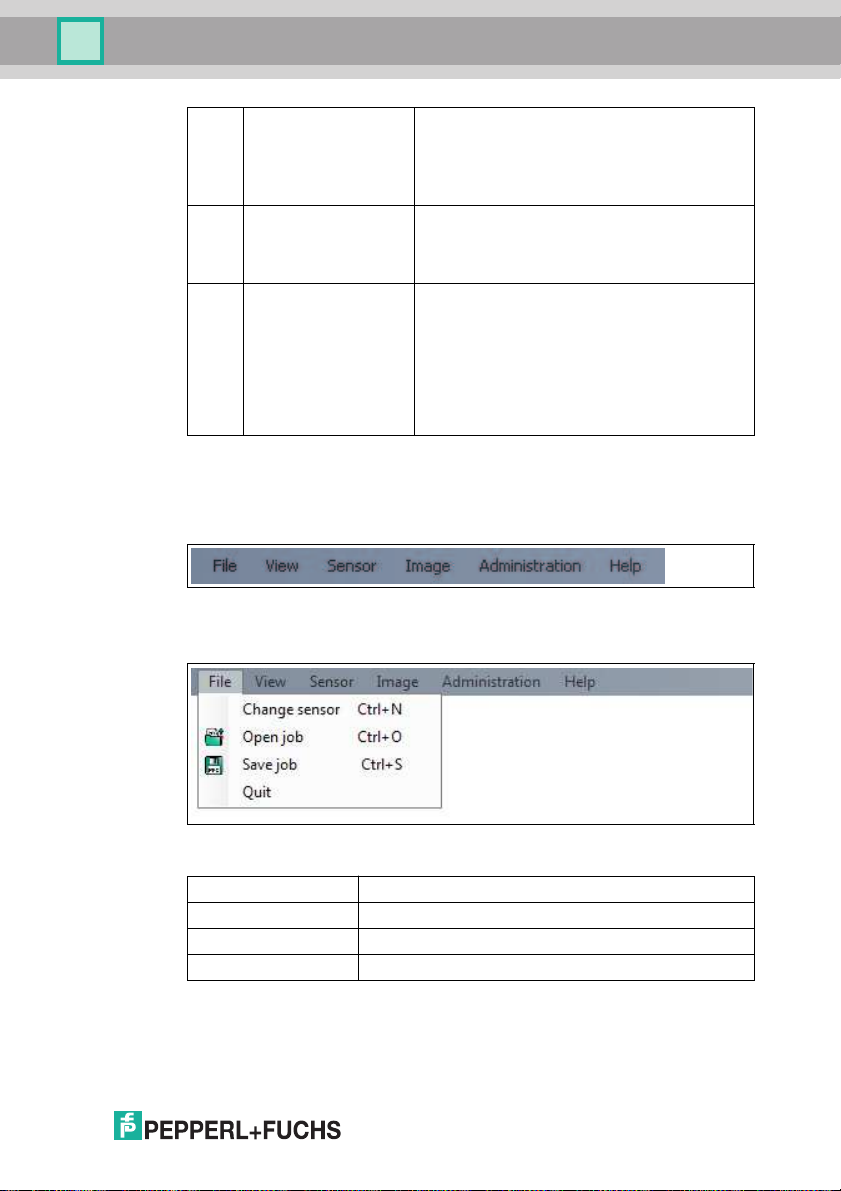
The menu bar conta ins a list of menu items. The functionality depends on the type
of sens or that is connected and the permissions of the user logged in.
Figure 7.1 Menu Bar
■ A varying number of tabs can be dis played
depend ing on which sensor is connected
■ Thi s field can be enabled or disabl ed via Show
results
error me mory
■ Thi s field can be enabled or disabl ed via Show
images
the pixel under the mouse pointer. The followi ng
items are displayed:
■ Imag e size
■ Zoo m level
■ Mouse posi tion in image coordinates
■ Current grays cale value
■ Imag e number
7.2.1 File Menu
Figure 7.2 File m enu
Change sensor Disconnects t he sens or and r eturns to the Login dialog .
Open jo b Loads a sensor configuration stor ed on th e PC.
Save job Saves the cu rrent sensor con figuration on the PC.
Quit Terminates the program.
Table 7.1 F ile Menu
2015-0 7
27
Page 28
OPC / OPD / OPE
Vision Configurator Software
7.2.2 View Menu
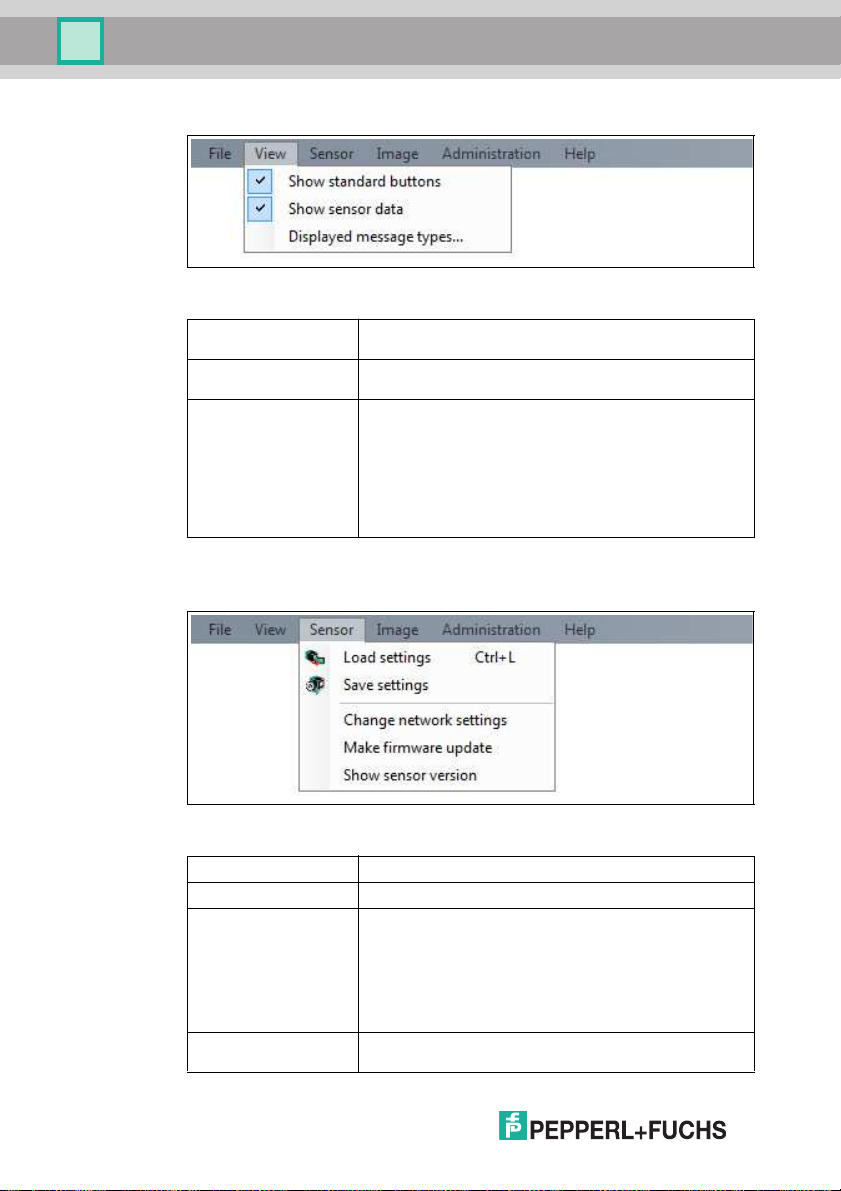
Figure 7.3 View menu
Show stan dard
buttons
Show se nsor data Hi des the output of the sensor data in the top right of the
Displaye d messag e
types
Table 7.2 V iew menu
7.2.3 Sensor Menu
Figure 7.4 Sensor men u
Load se ttings... Loads the saved settings from the sensor
Save settings... Saves the settings to the sen sor
Change network
setting s...
Make firmware
update...
28
Toggl es the disp lay of the buttons in the bar on the left on and
off.
screen.
This item enables you to specify which types o f message are
to be o utput by the sensor. Output messages of the selected
types are displ ayed in the Sensor output column on the
right.
Info: Information is displayed
Warning: Warning s are displayed
Error: Errors are outp ut
Critical: Serious errors are output
Assert: Internal errors are displ ayed
If the sensor is connected to the PC via Ethernet, this
comm and enables you to change some of the connection
settings on the sensor. Onc e you ha ve changed them, the
connection betw een Vision Configurator and the sensor is
automatically disconnec ted. If required, change the netw ork
address to the new ly allocated IP and re connect Vision
Configurator to the sensor. Press the Connect button to o pen
the Log in screen again.
Performs firmware up dates. This command should be used
by experienced users only.
2015-0 7
Page 29
OPC / OPD / OPE
Vision Configurator Software
Show se nsor
version...
Table 7.3 S ensor menu
Note!
Firmware Update
Once you have upgraded the firmware and Update complete is displayed, restart
the sens or.
7.2.4 Image Menu
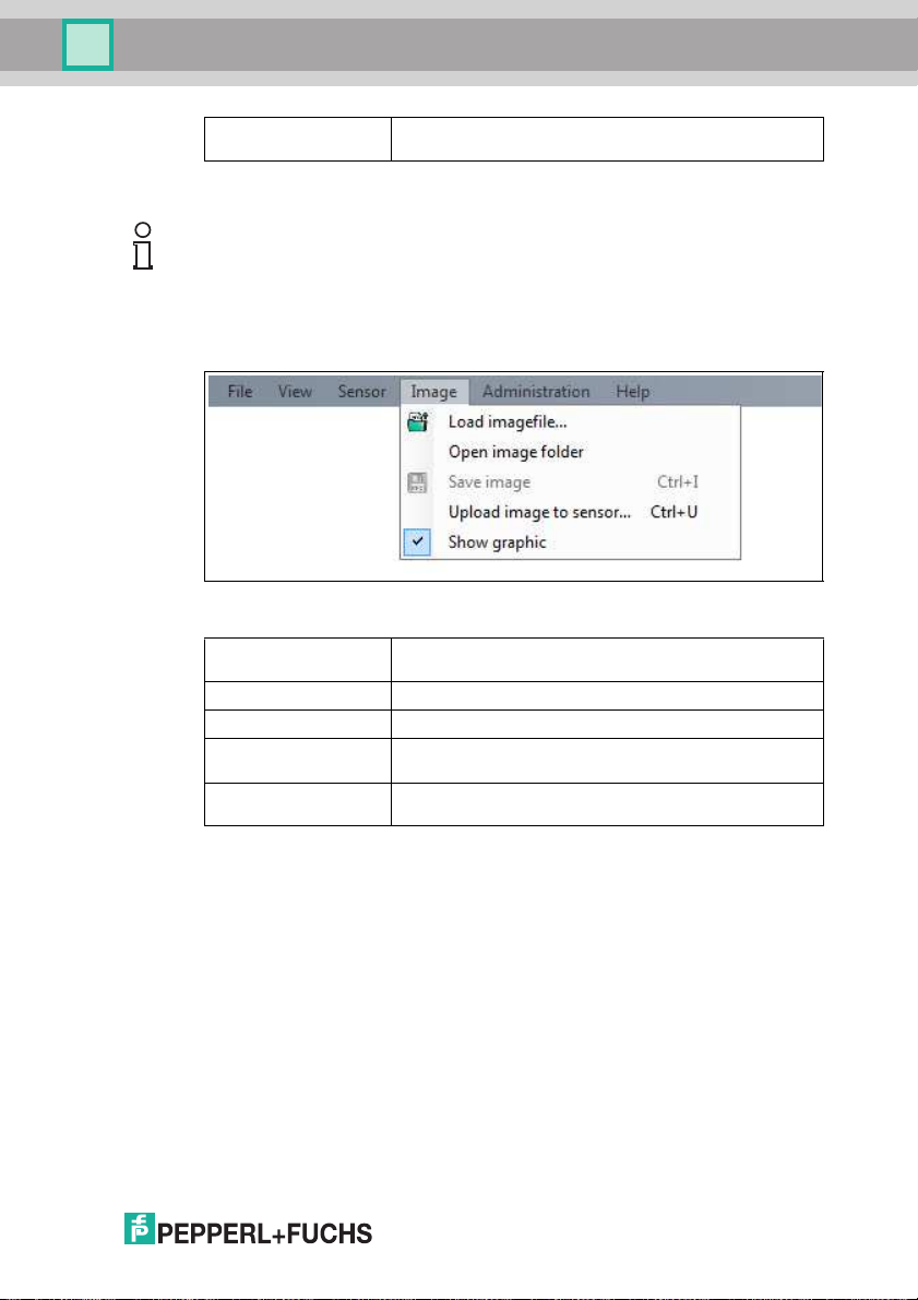
Figure 7.5 Imag e menu
Load ima gefile Opens an image file and displays the ima ge in the image
Open im age folder Opens the folder in which i mages are currently saved.
Save ima ge Saves the i mage currently displayed on the P C.
Upload image to
sensor
Show graphic Turns display data sent from the se nsor on and off in the
Table 7.4 I mage Menu
Displays the sensor version numb er.
display.
Uploads an im age file from the PC to the sensor.
image.
2015-0 7
29
Page 30
OPC / OPD / OPE
Vision Configurator Software
7.2.5 Administration Menu
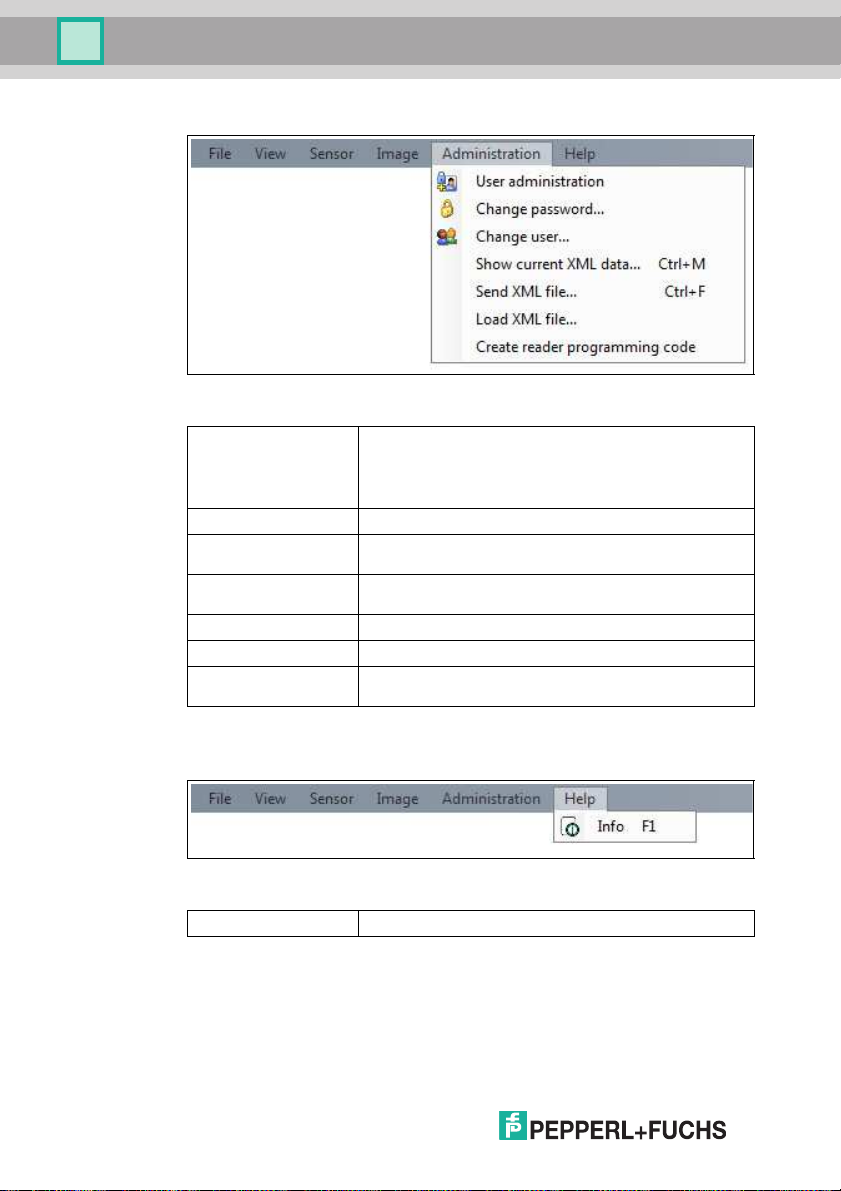
Figure 7.6 Administration menu
User ad minis tration Opens a wi ndow which dis plays all the currently c reated
Change passwo rd Chang es th e current user's password.
Change user The Login screen opens and a different user and /or sensor
Show c urrent XM L
data
Send XML file... Saves the XML data on a com puter.
Load XML file... Loa ds XML data from a comp uter.
Create reader
programming code
Table 7.5 Administration menu
7.2.6 Help Men u
Figure 7.7 Help menu
Info Displays information about Vision Configurator.
Table 7.6 H elp menu
users at the same authorization level or lower. New users w ith
the sam e authorization level or lower can also be created and
deleted here. In ad dition, a user passwo rd can be reset to the
default password for the relevant user level.
can be selected.
Loads the current XML data from the sensor and displays it in
a separate window.
Enables the use r to create cont rol codes that ca n assign the
senso r a device name and an IP address.
30
2015-0 7
Page 31
OPC / OPD / OPE
Vision Configurator Software
7.3 Configuration window
Various parameters are specified in the configu ration w indow. The individual
parame ters depend on the current authorization level and are, therefore, not
always all visible. Some features are available in d ifferent variants only.
Depending on the p aramete rs set, so me fields will be grayed out.
7.3.1 System Tab
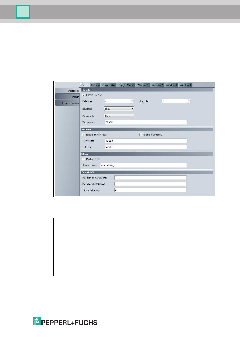
System Tab, Interfaces Me nu Item
Figure 7.8 System tab, Interface s menu item
RS-232
Enable RS-232 Enables or disables RS-232 trans mission
Data size Number of data bits. Adjustment rang e 5 ... 8
Stop bits Num ber of stop bits. Adjustment rang e 1 ... 2
Baud rate Se lection of the baud rate
2015-0 7
■ 9 600
■ 5 7600
■ 3 8400
■ 1 9200
■ 1 15200
31
Page 32
OPC / OPD / OPE
Vision Configurator Software
Parity mode Setting for detectio n of transmiss ion e rrors
Trigger string Defin ition of the trigger str ing that can be used to trigger a
■ N one
■ O dd
■ E ven
Result output via TCP/IP
trigger command via the RS-232 interface
Network
Enable TCP/IP result Result output via TCP/IP
Enable UDP result Result output via UDP (User Datagram Protocol)
TCP/IP por t Entry of the corresponding port
UDP port Entry of the corresponding port
Other
Position LEDs Activation of the position LEDs
Sensor name Enter a device name for t he sensor. The devic e nam e can b e
used instead of the IP ad dress to connect to the sensor
Digital I/O
Pulse length G OOD [ms] Length of the output s ignal for a successful
Pulse length BA D [ms] Length of the output sig nal for a failed read
Trigger delay [ ms] Delay for a trigger
read
Value range: 0 ... 30,000 ms
0 means that the output signal is not res et
Value range: 0 ... 30,000 ms
0 means that the output signal is not res et
Value range: 0 ... 30,000 ms
32
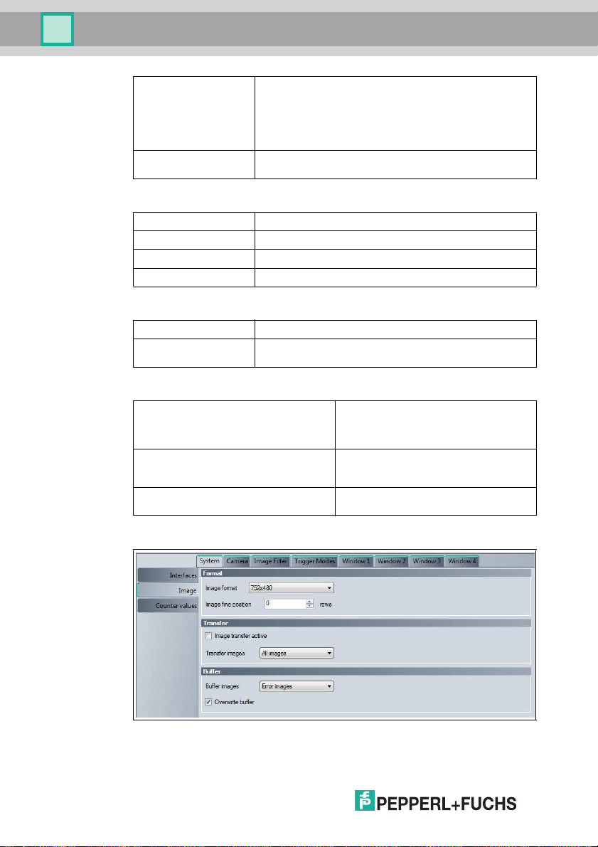
System Tab, Image Menu Item
Figure 7.9 System tab, Image menu item
2015-0 7
Page 33
OPC / OPD / OPE
Vision Configurator Software
Format
Image format Selects the image size
Image fine position Moves the field of view up or down (line by line)
Transfer
Image transfer active Image transfer from the sensor to Vision Configurator
Transfer images Determines which images are t o be transferred to Vision
Buffer
Buffer images Speci fies whic h images are to be saved.
Overwrite buffer If this is enabled, the image memory is
■ 7 52x480 (full screen)
■ 7 52x240
■ 7 52x160
■ 7 52x120
Selecti ng a smaller field of view can increase the reading
speed.
The field of view can be moved o nly if you select a field o f
view ins tead of the full sc reen under Image format.
Configurator
■ A ll images: All ima ges
■ E rror im ages: Images from failed reads
■ G ood images: Images from successful reads
The m emory holds approx. ten images.
■ All image s: All images
■ Error ima ges: Images from failed reads
■ Go od images: Images from succ essful
reads
continuously overwritten with new images.
In other words, if this is enabled , the image
memory contains the last ten images that
correspo nd to the settings configured
under Buffer image s. If it i s disable d, the
image memory contains the first ten
images that correspond to the settings
configured und er Buffer images.
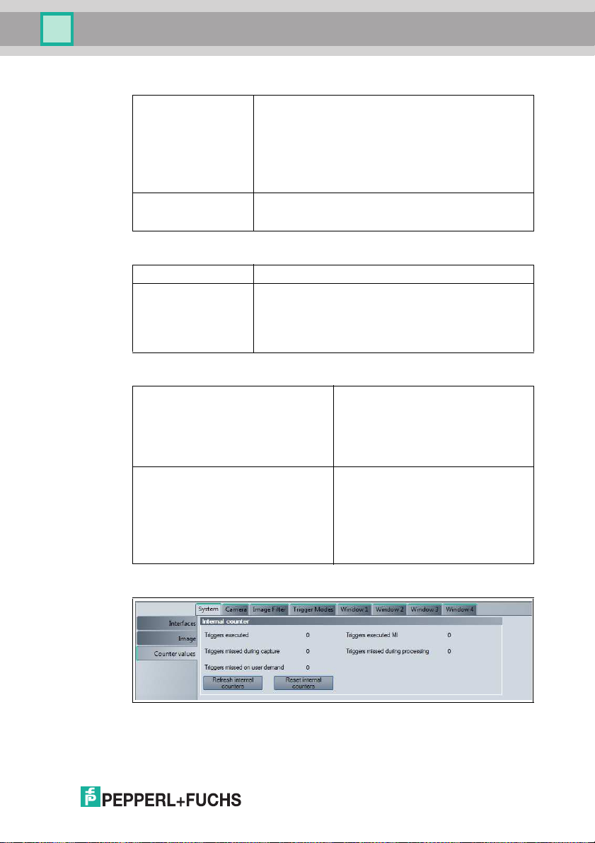
System Tab, Cou nter Values Menu Item
Figure 7.10 System tab, C ounter Values menu item
2015-0 7
33
Page 34
OPC / OPD / OPE
Vision Configurator Software
Internal Coun ter
Triggers executed Counter for executed trigger signal
Triggers executed MI Counter for codes that extend over multiple
Triggers missed during capture Co unter for trigg ers that were not executed
Triggers missed during processing Counter for trigg ers that were not executed
Triggers missed on user dem and Counter for triggers that were not executed
Refresh internal counters Updates the counter values in Vision
Reset internal counters Resets the counter values to 0
Note!
The counter values are not automatically inc reased in Vision Configurator. To
retrieve th e curren t coun ter value s, click Refresh internal counters.
7.3.2 Camera Tab
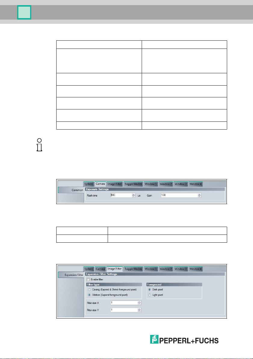
Camera Tab, Common Menu Item
image captures
For examp le, if two images h ad to be
evaluated when reading a long barcode,
this c ounter inc reases the co unt by one.
when capturing an imag e
when evaluating an imag e
as a result of user intervention
Configurator
Figure 7.11 Camera tab, Common menu item
Exposure Settings
Flash time Exposure time setting in µs
Gain Gain setting
7.3.3 Image Filter Tab
Image Filter Tab, Expansion Filter Men u Item
Figure 7.12 Image Filter tab, E xpansion Filter menu item
34
2015-0 7
Page 35
OPC / OPD / OPE
Vision Configurator Software
Expansion Filter Se ttings
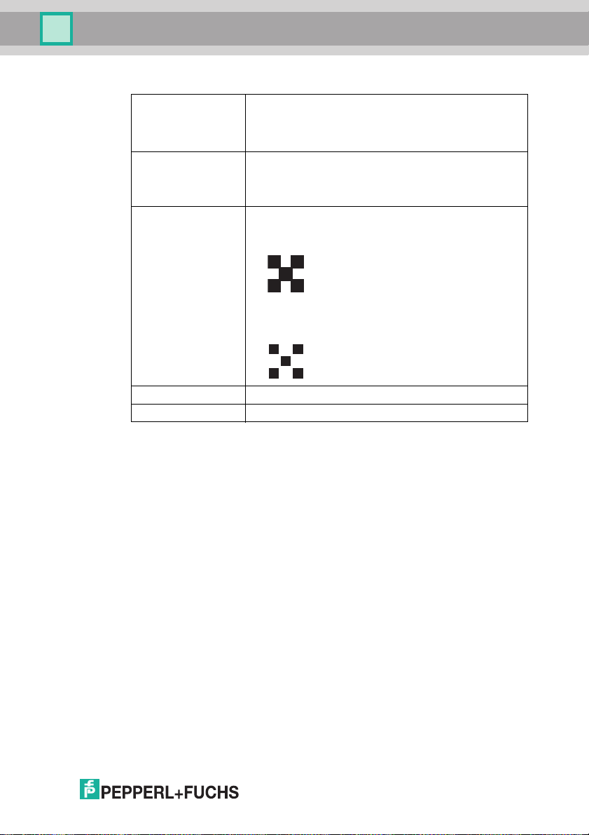
Enable filter Enab les or di sables expansion of the modules, i.e., the points
Filter type ■ Closing: Fills gaps betw een light or dark areas depending
Foreground ■ Dark pixel: The settings under Filter type relate to dark
Filter size X Select the expansion factor in the X dire ction.
Filter size Y Select the expansion fa ctor in t he Y direction.
used to generate the code. This allows mod ules of
needl epunched codes to be expanded so that they can be
read mo re reliably. However, using this filte r increases the
evaluation time.
on the setting
■ Dilation : Magnifies light or dark areas dependi ng on the
setting
areas.
For example, if Dilation is selected, dark ar eas are
expanded, shrink ing the surrounding light areas.
■ Light pixel : The settings under Filter type relate to light
areas.
For example, if Dilation is selected, light areas are
expanded, shrink ing the surrounding dark areas.
2015-0 7
35
Page 36
OPC / OPD / OPE
Vision Configurator Software
7.3.4 Trigger Modes Tab
Trigger Modes Tab, Setup Menu Item
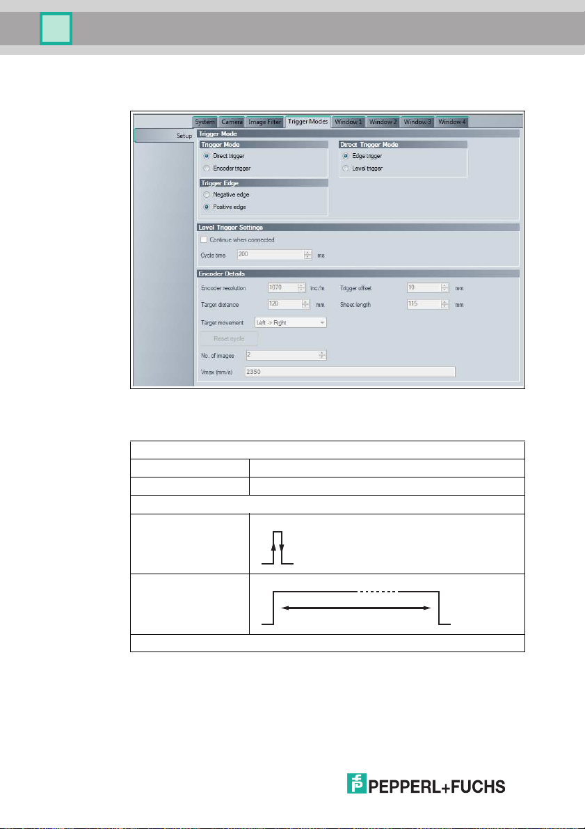
Figure 7.13 Trigger Mode s tab, Setup menu item
36
Trigger Mode
Trigger mod e
Direct trigger Trigger is evaluated directl y
Encode r trigger Trigger is generated by rotary enco der increments
Direct Trigger Mode
Edge trigger Trigger signal edge activates a trigger
Level trigger Si gnal level triggers a conti nuous trigger
Trigger Edge
2015-0 7
Page 37
OPC / OPD / OPE
Vision Configurator Software
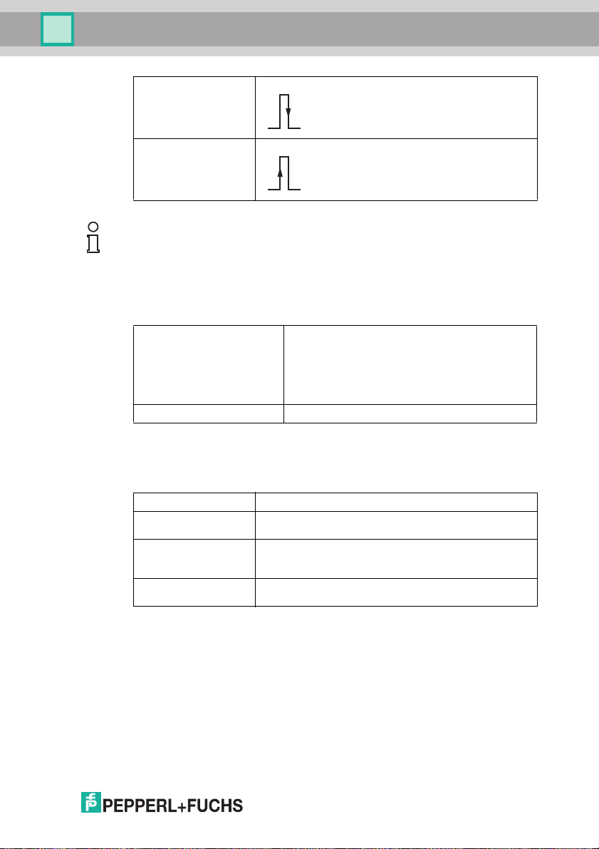
Negative edge The falli ng edge activates a trigger
Positive edge T he rising edge activates a trigger
Note!
Use the Encoder trigger trigg er mo de in conjunc tion with 1-D barcodes only.
The Level Trigger Settings menu item is active only if you have s elected Level
trigger und er Direct Trigg er Mod e.
Level Trigger Settings
Continue whe n conne cted Emergency switc h for a continuous trigger. If this i s
Cycle time Time between two r eads in ms
enabled , the sensor operates continuo usly. Disable
this opti on to interrupt the sens or's task.
For example, if Level trigger is selec ted in conjunction
with Negative e dge, the sens or will operate
continuously until the next rising edge occurs. Disable
this opti on to interrupt this status.
The Encoder Details menu item is active only if yo u have selected Encoder
trigger und er Trigg er Mod e.
Encod er Details
Encode r resolution Rotary encoder resoluti on in increments/m
Trigger offset Distance in mm between trigger (e.g., li ght barrier) and optical
Target distance Read dis tance in mm
Sheet length Object's length in mm
2015-0 7
axis of sensor
Distance from the sensor lens to the object on which the code
is located (OPC120* only)
Length of the obj ect on which the co de is located
37
Page 38
OPC / OPD / OPE
1
2
Up -> Down
Down -> Up
Left -> Right Right -> Left
1
2
3
4
Vision Configurator Software
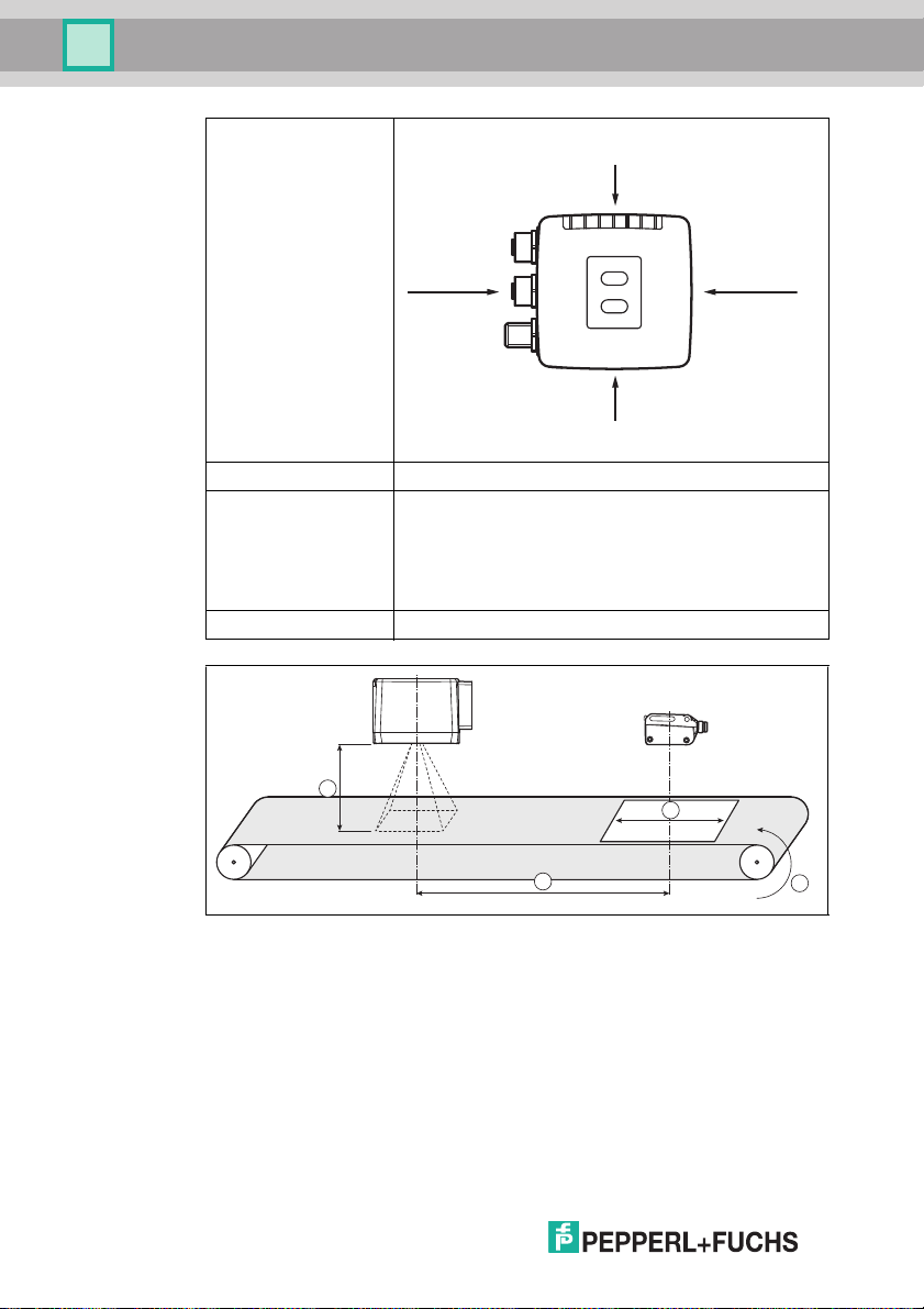
Target movement Code's direction of movement from the sensor's perspec tive
Reset Cycle Interruption of the cycle
No. of ima ges The se nsor use s the Encoder resolution, Trigger offset,
Vmax (mm/s) Maxim um speed of the object
Target distance, and Sheet length values to automatically
calculate the num ber of reads and the trigger times they
require to capture the e ntire obj ect.
If the number of images is greater than the image memory
available, the application i s not feasib le because the entire
object cannot be captur ed.
1. Target distance: Read distan ce in mm
2. Trigger offset: Distance in mm between trigger and sen sor's o ptical axis
3. She et len gth: Obje ct's leng th in mm
4. Encoder resolution: Rotary encoder reso lution in increments/m
38
2015-0 7
Page 39
OPC / OPD / OPE
Vision Configurator Software
7.3.5 Window Tab
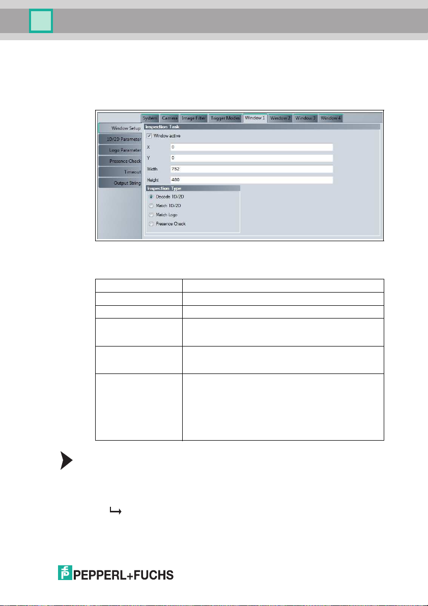
Four different tabs are available: Window 1 ... Window 4. Each tab has the same
layout.
Window Tab, Window Setup Menu Item
Figure 7.14 Window tab, Window Setup menu item
Inspection Task
Window active Activation of the window
X Top left position of the w indow in the X direction
Y Top left position of the window i n the Y direction
Width Width of the w indow
Height Height of the window
Inspection Type Option to select whether a code is to b e decod ed or
The width of the window can be read in the image displ ay at
the bottom left of the relevant window frame
The hei ght of the window can be read in the image dis play at
the bottom left of the relevant window frame
compared, whether a taught-in image area is to be retrieved,
or whether presence monitoring is to be performed
■ D ecode 1-D/2-D
■ M atch 1-D/2-D
■ M atch Logo
■ P resence Che ck
Chang ing the Window Size and Window Position
You can change the window size an d wind ow position e ither in the tab or in the
image display itself.
1. Click on t he frame of the window to b e edited in the ima ge display.
The fram e is now displayed in bold.
2. To change the position of the frame, move the cursor toward the cente r of the
frame until it change s into a cross hair.
2015-0 7
39
Page 40
OPC / OPD / OPE
Vision Configurator Software
Hold down the mouse button and drag the frame to the required position,
and t hen release the mouse button.
3. To change the size of the frame, move the cursor to one of the corners of the
frame until it change s into a double arrow.
Hold down the mouse button and drag the frame to the required size, and
then r elease the mo use button.
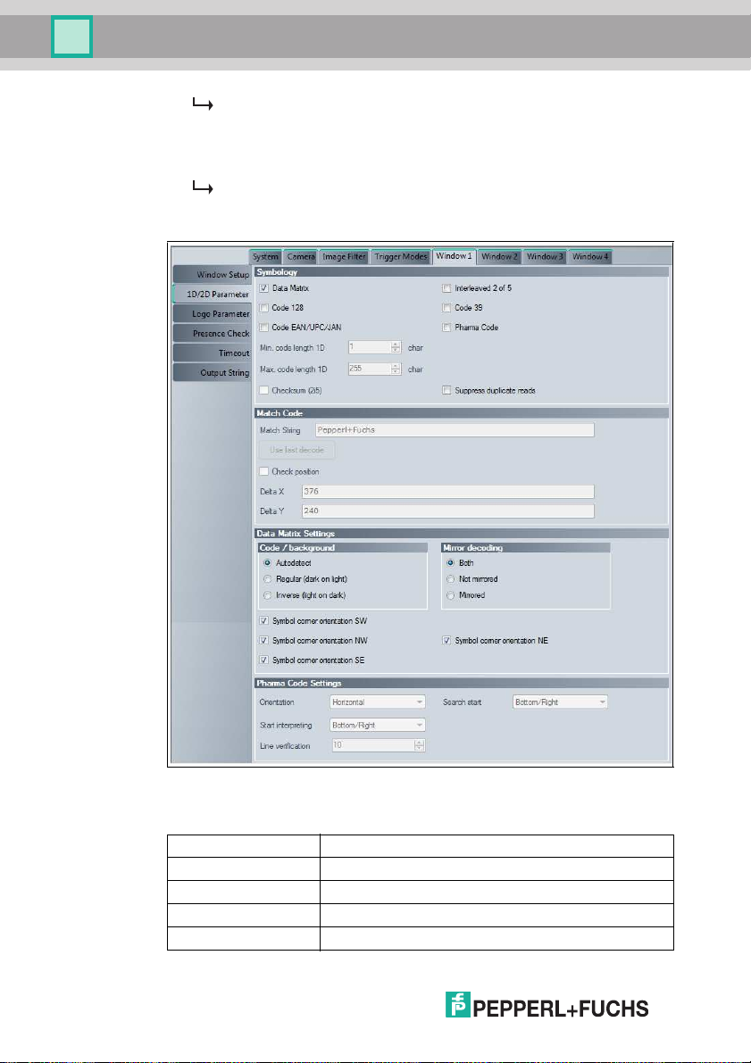
Window Tab, 1D/2D Parameter Menu Item
40
Figure 7.15 Window tab, 1D/2D Parameter menu item
Symbology
Data Matrix Activates o r deactivates reading of Data Matrix codes
Interleaved 2 of 5 Activates o r deactivates reading of interleaved 2 of 5 codes
Code 128 Activates o r deactivates reading of cod e 128 codes
Code 39 Activates or deac tivates reading of cod e 39 codes
Code EAN/UP C/JAN Activates or deactivates reading of EAN/UPC/JAN codes
2015-0 7
Page 41
OPC / OPD / OPE
N
S
W E
NE
SE
SW
NW
Vision Configurator Software
Pharma Code Ac tivates or deactivates reading of Pharmacodes
Min. co de length 1D Enters the minimum code len gth for 1 D barcodes
Max. cod e length 1D Enters the m aximum cod e length for 1D barcodes
Checksum (2i5 ) Evaluates th e checks um for interleaved 2 of 5 codes
Suppress duplic ate
reads
The Match Code menu item is active on ly if you have selected Match 1D/2D
under Ins pection Type in Window Setup.
Match Code
Match string Enters the compar ison s tring
Use last decode The last result string read is taken as the new comparison
Check position Checks the positi on of the read code
Delta X Ho rizontal range (+/- ) in wh ich the decoding is evaluated as
Delta Y Verti cal range (+/-) in which the decoding i s evaluated as
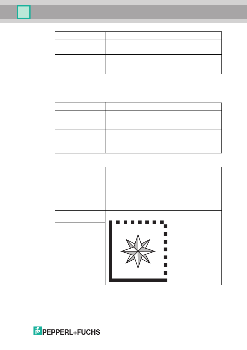
Data Matrix Settings
Code / background ■ Autode tect: Automatic detec tion of the code color and
Mirror Decodin g ■ Both: Reads mirrored and non-mirrored codes
Symbol corner
orientatio n SW
Symbol corner
orientatio n NW
Symbol corner
orientatio n NE
Symbol corner
orientatio n SE
Enables or disables dup licate suppressio n, which prevents
the same code being read several times in successi on.
string
"good"
"good"
code backgro und
■ R egular (dar k on light): Dark code on a light bac kground
■ I nverse (light o n dark): Light cod e on a dark background
■ N ot mirrored: Reads non-mirrored codes
■ M irrored: Reads mirrored codes
Position of the cor ner formed from the continuous bound ary
lines (finder pattern) of the Data Matrix cod e
2015-0 7
The Pharma Cod e Settings m enu item is active only if you have enabled reading
of Pharmacodes in Symbology.
41
Page 42
OPC / OPD / OPE
Vision Configurator Software
Pharm a Code Settings
Orientation Orientation of the Pharmacod e
Search start Dir ection from whic h a Pharmacode search is to start
Start interpreting Direction from which the P harmacode is to be interpreted
Line verification Number of bars constitut ing the Pharmacode
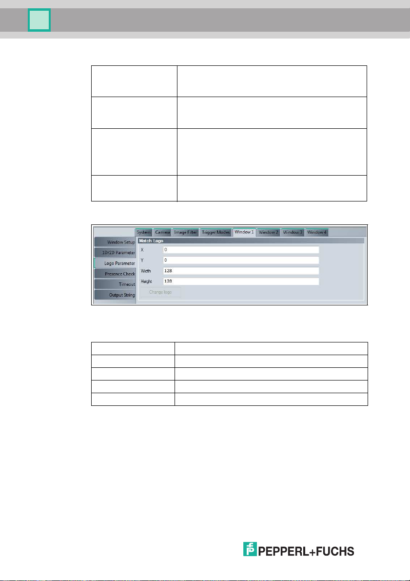
Window Tab, Logo Parameter Menu Item
■ Horizontal: Horizontal
■ Vertical: Verti cal
■ Bottom/Right: From the bottom right
■ Top/Left: From the top left
■ Bottom/Right: Starting from the bottom or from the righ t,
depending on the orientation of the Pharmacod e
■ Top/Left: Starting from the top or from the left, depending
on the orientation of the Pharm acode
Spec ifying this prevents accidental interpretation of too
ma ny or too few lines.
42
Figure 7.16 Window tab, Logo Parameter m enu item
Match Logo
X X position of the New logo area window
Y Y posi tion of the New logo area window
Width Width of the New logo area window
Height Height of the New logo area window
Change logo Activates the New logo area window
You can change the height and width of the New l ogo area window in 64 steps
only.
2015-0 7
Page 43
OPC / OPD / OPE
Vision Configurator Software
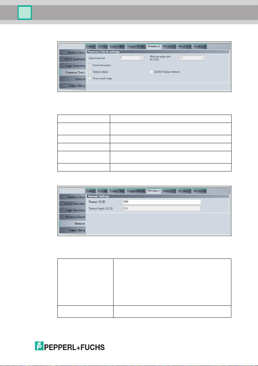
Window Tab, Presence Check Menu Item
Figure 7.17 Window tab, Presence Check menu item
Presenc e Check Settings
Edge threshold Measurement for the shape of the edge
Minimum edge ratio
(0 - 2000 )
Horizontal edges Activates counting of horizontal edges
Vertical edges Activate s counting of vertical edg es
GOOD if below
minim um
Show resu lt ima ge The edge im age is plotted in the input image
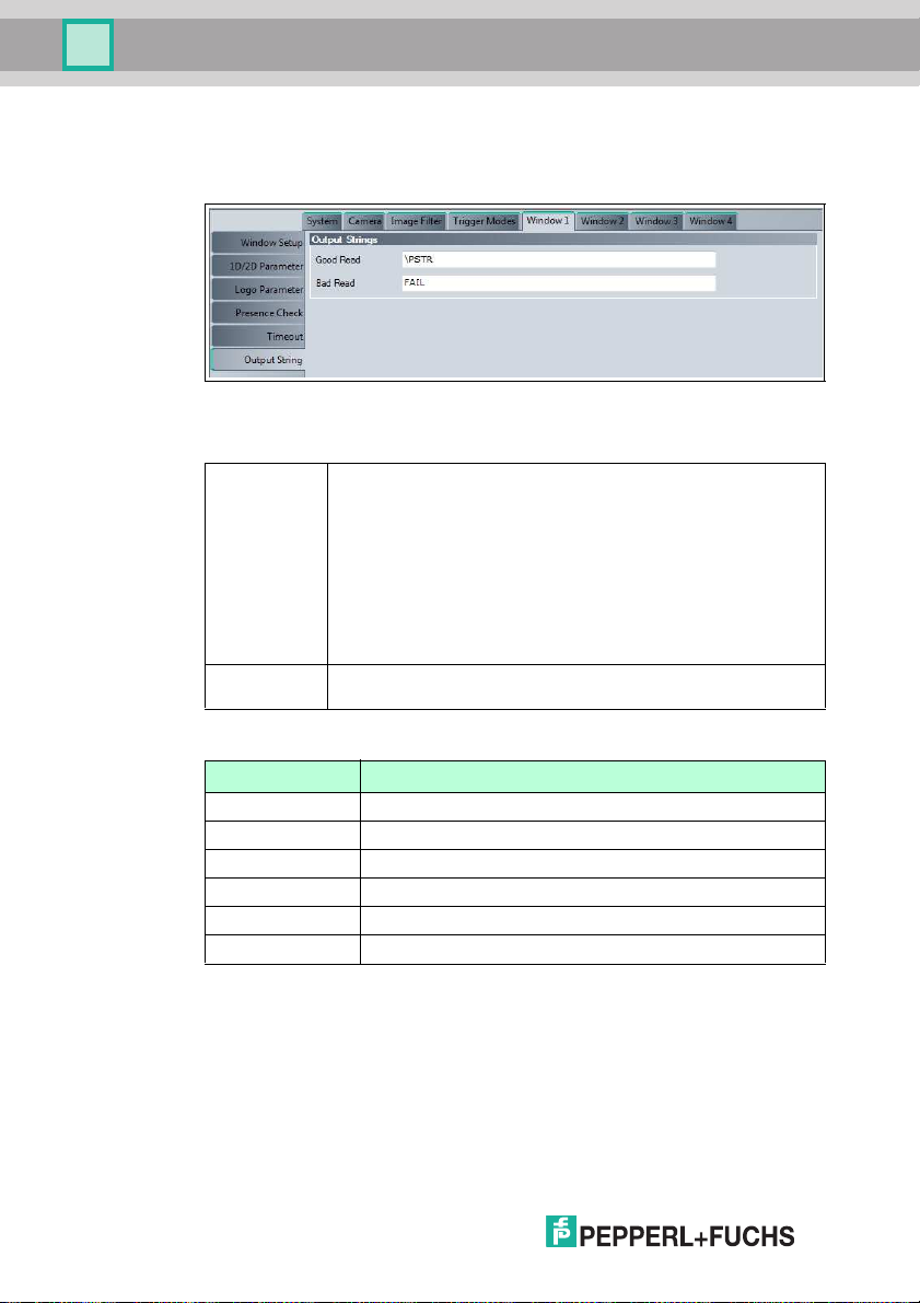
Window Tab, Timeo ut Men u Item
Measurement for the nu mber of edges in the image area, up
to a maximum of 2000
The result is "go od" if the number of edges in the im age area
is below the Minimum edge ratio value
Figure 7.18 Window tab, Timeout menu item
Timeout Settings
Timeout 1-D/2-D Maximu m duration for the image capture and dec oding of
Timeout Match 1-D/2-D Maximum duration for inspection type Match 1D/2 D in
2015-0 7
the co de in milliseconds. If the read times out, it is
consid ered to have faile d.
The image capture time is the time required to transfer the
image to the memory. This time depends on the Image
form at image size that you have set under System >
Imag e > Format.
The decoding time depends on the symbology and code
quality. The decoding time is displayed on the Vision
Configurator image di splay under Time. See chapter 7.7
millisec onds.
43
Page 44
OPC / OPD / OPE
Vision Configurator Software
Only one input field is active at a time. Depending on the inspection type selected,
the related input field is active.
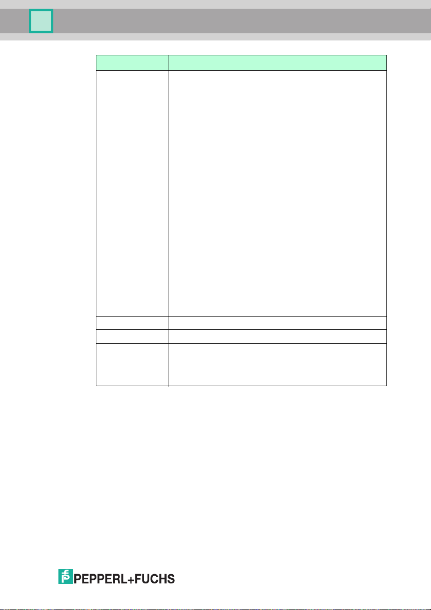
Window Tab, Output String Menu Item
Figure 7.19 Window tab, Outp ut String menu item
Output Strings
Good Read This allows you to specify which data string is outpu t for a suc cessful
Bad Re ad This allows you to specify which data string is outpu t if the read was
read. You can enter both normal characters and predefined parameters
that output a specific data string. You can also output several
parameters in succession.
Examples:
■ \PSTR outp uts all content of the read code.
■ \PISO outp uts various properties relating to the code quality. If, for
unsuccessful.
example, the contrast deteriorates continuously, this may in dicate
decreasing ink levels in the code printer. If the axial nonuniformity of
the cod e increases, t his may indicate that the paper rolls are running
too fast.
44
Output Strings
Parameters D escription
\PSTR Returns all content of the code if the read was success ful.
\PSTR(pos,l en) Outputs len characters from positi on pos of the code
\PSTR(E,len) Outputs the last len character s of the code
\PLEN O utputs the length of the read code (4-digit)
\PTIM O utputs the time r equired to read the code in ms (4-digit)
\PTST Outputs a timestamp in ms (10-digit)
2015-0 7
Page 45
OPC / OPD / OPE
Vision Configurator Software
Parameters D escription
\PISO This parameter can be used in the Good Rea d field only, as the
\PCXL O utputs the X coordinate of the code's c entral po int.
\PCYL Outputs the Y co ordinate of the code's ce ntral poi nt.
\cc Control characters, cc (2-digit, hexadecimal), e.g.,
values can be output only if a code was success ful.
Outputs the code quality based on eig ht properties, in accordanc e
with ISO /IEC 16022:2006. A mark between 0 (bad) and 4 (good) is
outp ut for each property.
■ OG: overall grad e
The overall quali ty is derived from the worst value for the other
properties.
■ SC: symbo l contrast
Indicates the extent to which the code stands out against the
background.
■ ANU: axial nonuniformity
Indicates the uniformity of the code in the axial direction.
■ GNU: grid nonuniformity
Indicates the uniformity of the points, i.e., the points co nstituting
the cod e.
■ MOD: modulation grade
Indicates how eas ily light points can be distinguished from dark
ones.
■ FPD: fixed pattern damage
Indicates whether defined areas are present, e.g., the
surrou nding quiet zone or the alignmen t pattern.
■ UEC: unused err or correc tion
Indicates the extent to which error correctio n was required to
read t he code.
■ PG: print growth
Indicates the exten t to which points have increased in size, e.g.,
due to the ink running .
■ 0D = CR (carriage return)
■ 0A = LF (line fee d)
■ 5C = \ (backslash)
2015-0 7
45
Page 46
OPC / OPD / OPE
Vision Configurator Software
7.4 Toolbar
The toolbar contains various function icons.
The connection between the PC and the sensor is
disconnected.
Opens a saved setting.
Saves the settings made.
Settings are read out from the sen sor.
All settings made are saved on the sensor.
46
Initiates a trigger. De pending on the sensor operating mod e,
the sensor returns a single measured value or continuous
measur ed values.
Resend s the las t fault pattern.
2015-0 7
Page 47
OPC / OPD / OPE
Vision Configurator Software
7.5 Sensor Data
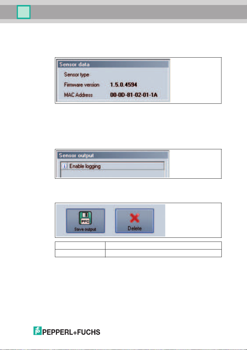
This are a shows the type of sensor conne cted, the firmware version of the
connec ted sens or, and the MAC address.
Figure 7.20 Sensor data
7.6 Sensor Output
This are a shows the commun ication b etween the Vision Configurator and the
connec ted sens or. To select wh ich messages are to b e disp layed, select View >
Displayed mess age types.
Figure 7.21 Sensor output
Two buttons are located in the lower are a.
Save output Saves the content of the w indow to a text file.
Delete Deletes the co ntents of the window.
2015-0 7
47
Page 48
OPC / OPD / OPE
Vision Configurator Software
7.7 Image Display
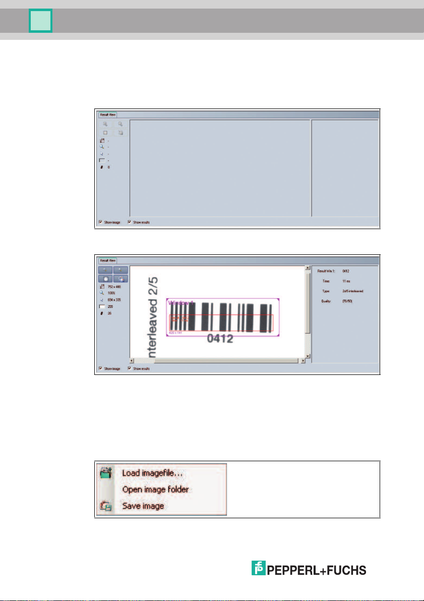
The image display has differe nt options for displaying the c apture d data. The
Show image and Show results check boxes c an be used to activate and
deactivate the image display and result display.
Figure 7.22 Result View screen
48
Figure 7.23 Result View screen with image d isplay and result display
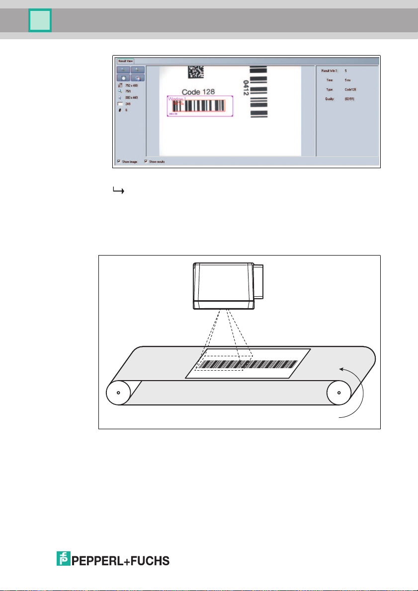
Different results are shown in the result display, depending on the type of
inspection. In the exam ple shown , the c ode read out, the decoding time required,
the type of code read, and the po sition o f the code read (qua lity) are displayed.
When you press the right mo use button or the context menu button, the following
context menu ap pears:
Figure 7.24 Result View context menu screen
2015-0 7
Page 49
OPC / OPD / OPE
Vision Configurator Software
Context Menu
Load ima ge file... Loads a sensor i mage. You can select the senso r image
Open im age folder Opens the storage location
Save ima ge Saves the d isplayed sensor image
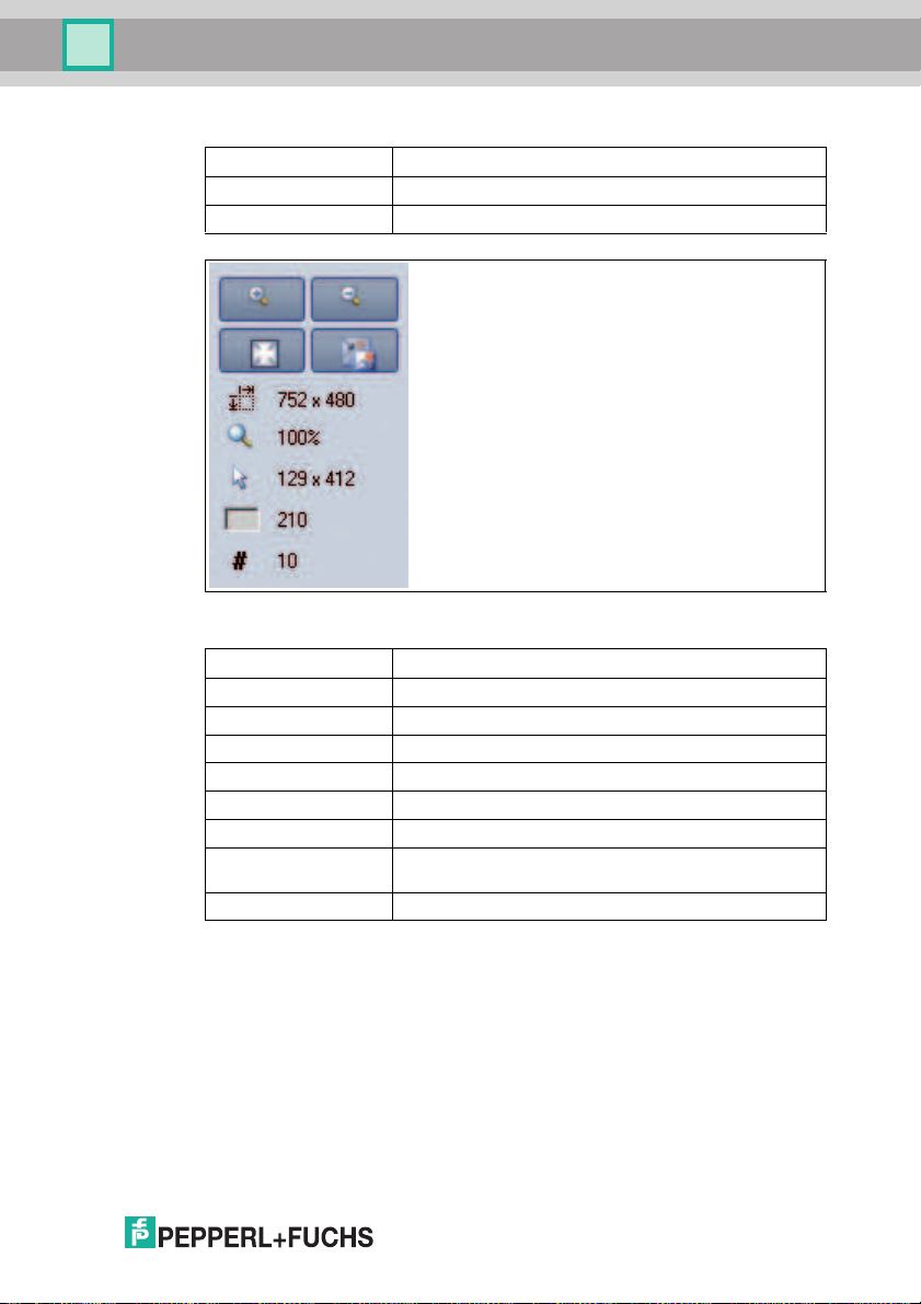
Figure 7.25 Image View toolbar screen
Magnifier + Zooms in on sensor image
Magnifier - Zoom s out on sensor image
Fit to w indow Fits the senso r image to the window
Origin al size Sets original imag e size
Size details Specifies the size of the sensor image
Zoom factor Displays the zoom factor. Zoom factor 1 is the original si ze
Position details Specifi es the position of the cursor
Grayscale value
details
Image numbe r Sp ecifies the im age number
Table 7.7 Re sult View toolbar menu
Grayscale value details for the pixel indic ated by the cursor
2015-0 7
49
Page 50
OPC / OPD / OPE
Operati on
8 Operation
You can select up to four different functions ( inspection types).
If more than one ins pection type ( more than one window tab) is activated, all the
read co des m ust be OK for the decoding in order to output a g ood read.
8.1 Reading a 1-D/2-D Code
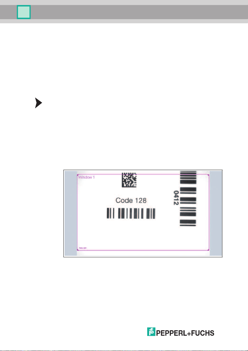
You can proce ss up to four different 1-D/2-D codes with o ne image capture using
the sens or. To do this, enable tabs Window 1 ... Window 4. If more than one tab
is enab led, all read codes must be OK to output a goo d read.
Reading 1-D/2-D Codes
1. Select Decode 1D/2D in the Window Setu p men u item in the Win dow 1 configuration window. See chapter 7.3.5
2. Set the symbology to be read in the 1D/2D Parameter menu item in the
Window 1 configuration window.
3. Make sure that the window is switched to active in the Window Setu p menu
item in the Window 1 configuration wind ow.
4. Place the first sheet with the code to be rea d under the sensor.
5. Click Trigger. The captured image will be shown in the image d isplay.
6. Click the frame labeled Window 1.
50
7. Adjust the s ize of the frame if ne cessary.
8. Click Trigger. The captured image will be shown in the image d isplay.
2015-0 7
Page 51
OPC / OPD / OPE
Operati on
9. The result from the read c ode is displayed in th e result window.
The sensor is set up to read codes .
8.2 Reading Overlong 1-D Codes
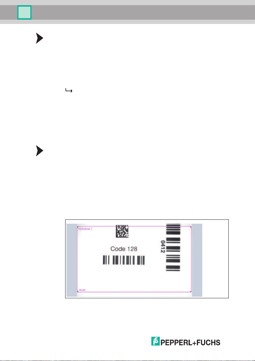
In ad dition to stan dard 1-D/2-D c odes, the sens or can read overlong barcodes
that extend beyond the sensor's capture range. The sensor does this by capturing
several images and evaluating them in succession to obtain a result.
Figure 8.1 Reading Overlong 1-D Barcodes
2015-0 7
51
Page 52
OPC / OPD / OPE
Operati on
Reading Overlong 1-D Codes
1. Set the sy mbology to be read in the 1D/2D Parameter men u item in the W in-
dow 1 configuration wind ow. Note that the function for reading overlong codes
can b e use d with 1-D cod es only. See chapter 7.3.5
2. Enable the Enco der trigger trigge r mode in the Setup menu item in the
Trigger Modes configurat ion window.
3. Enter the values for the Encode r resolution, Trigge r offse t, Targe t
distance, Sheet length, and Target movement. See chapter 7.3.4
The sensor automatically calculates the nu mber of images required to
capture the whole o bject, including the overlong barcode. If you need to
capture only the barcode rather than the whole object, you ca n enter the
length of the barcode in the Sheet length field.
8.3 Comparing a 1-D/2-D Code
You can co mpare up to four different 1-D/2-D codes with one image capture using
the sens or. To do this, enable tabs Window 1 ... Window 4. If more than one tab
is enab led, all compa red codes must be OK to o utput a good read .
Comparing 1-D/2-D Codes
1. Select Match 1D/2D in the W indow Setup menu item in the Window 1 configuration window. See chapter 7.3.5
2. Set the symbology to be read in the 1D/2D Parameter menu item in the
Window 1 configuration window.
3. Make sure that the window is switched to active in the Window Setu p menu
item in the Window 1 configuration wind ow.
4. Place the first sheet with the code to be compared under the sensor.
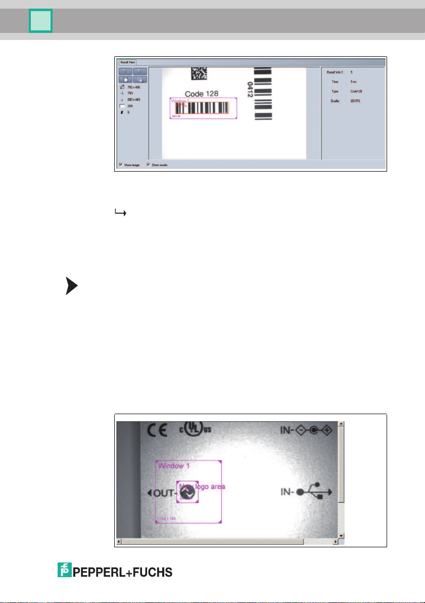
5. Click Trigger. The captured image will be shown in the image d isplay.
6. Click the frame labeled Window 1.
52
7. Adjust the s ize of the frame if ne cessary.
8. Click Trigger. The captured image will be shown in the image d isplay.
2015-0 7
Page 53
OPC / OPD / OPE
Operati on
9. Enter the code to be compared under Match Code in the 1 D/2D Parameter
menu item of the Window 1 configuration window. You can adopt a previously
read code via the Use las t decode button.
The sensor is set up to compare codes.
8.4 Comparing a Logo
You can pro cess up to four differen t logos with one image capture us ing the
senso r. To do this, enable tabs Window 1 ... Window 4. If more than one tab is
enabled, all compared logos must be OK to output a goo d read.
Comparing Logos
1. Select Match Logo in the W indow Setup menu item in the Window 1 configuration window. See chap ter 7.3.5
2. Make sure that the window is switched to a ctive in the Wind ow Setup menu
item in the Window 1 configuration window.
3. Place the first sheet with the reference logo under the sensor.
4. Click Trigger. The captured imag e will be shown in the imag e display.
5. Click the frame labeled W indow 1.
6. Adjust the s ize of the frame if nec essary.
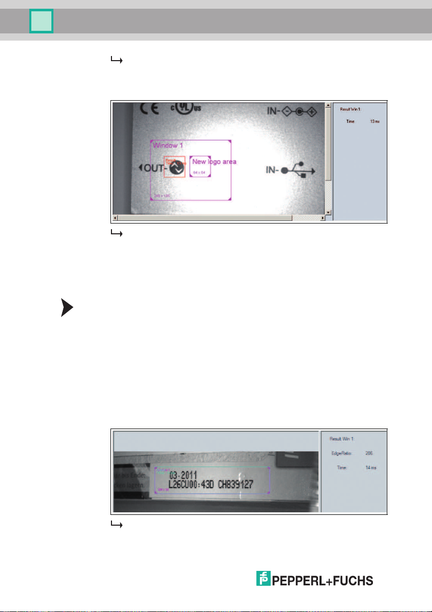
7. Click Change log o in the Logo Parameter men u item in the Window 1
configuration window.
2015-0 7
53
Page 54
OPC / OPD / OPE
Operati on
A new frame a ppears, labeled New logo area.
8. Move the New logo area frame over the reference logo.
9. Click Trigger.
The reference logo is taught in.
8.5 Checking the Presence of Materials with a Changeable Texture
You can check up to four different textures with one image capture using the
sensor. To do this, enable tabs Window 1 ... Window 4. If more than one tab is
enabled, all read textures must be OK to output a good read.
Presence Che ck
1. Select Presence Check in the Window Setup men u item in the Window 1
configuration wind ow. See chap ter 7.3.5
2. Make sure that the window is switched to active in the Window Setu p menu
item in the Window 1 configuration wind ow.
3. Place the first sheet with the field to b e checked un der th e sensor.
4. Click Trigger. The captured image will be shown in the image d isplay.
5. Click the frame labeled Window 1.
6. Adjust the s ize of the frame if ne cessary.
7. Click Trigger.
54
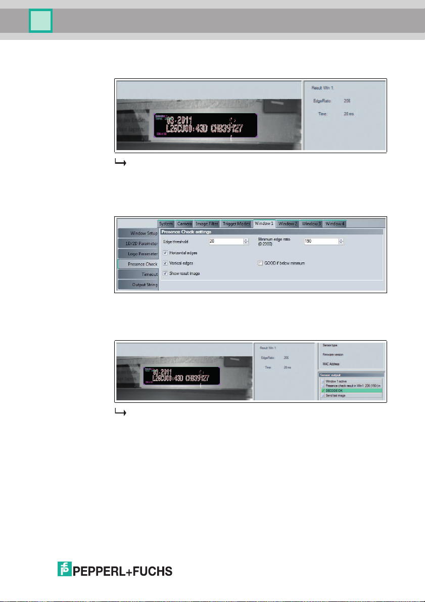
The captured image will be shown in the image display together with
additional information.
2015-0 7
Page 55
OPC / OPD / OPE
Operati on
8. Enable Show result image un der the Prese nce Check menu item in the
Window 1 configuration window, and click Trigg er again.
The resulting image is shown in th e image display. Edge transitions are
displayed in gra phic for m in the resulting image. The resulting value is shown
in the image display under Result Win 1.
9. Set the ed ge detection to be checked under Minimum edge ratio in the
Presence Check menu item in the Window 1 configuration window.
10. If the value read in is g reater than the value entered under Minimu m edge
ratio, DECODE OK is o utput. Conversely, if the result should be DECODE
OK when the value read in is lower th an the value ente red, en able the GOOD
if below minimum option.
The presence check is con figured.
2015-0 7
55
Page 56

OPC / OPD / OPE
Maintenance and Repair
9 Maintenance and Repair
9.1 Maintenance
To get the best possible performan ce out of your d evice, keep the optica l unit on
the device clean and clean it when n ecessary.
Observe the following instruc tions when cleaning :
■ Do not touch the optical unit with your fing ers.
■ Do not immers e the d evice in water. Do not spray the device with water or
other fluids.
■ Do not u se a s couring agent to clean the surface of the device.
■ Use a cotton or paper cloth moistened with water or isopropyl alcohol (not
soaked).
■ Remove any residual alco hol us ing a co tton or pape r cloth moistened with
distilled water (not soaked).
■ Wipe the surface of the devic e dry u sing a lint-free clot h.
9.2 Repair
The devices must not be repa ired, change d or m anipulated. If there is a defect ,
the product must always be rep laced with an original device.
56
2015-0 7
Page 57
OPC / OPD / OPE
Troubleshooting
10 Troubleshooting
10.1 What to Do in the Event of an Error
Before requesting a s ervice call, please check that the following actions have
been taken:
■ Equipment has been tested ac cording to the following checklists,
■ Telephone assistance obtained from the Serv ice Center to isolate the
problem .
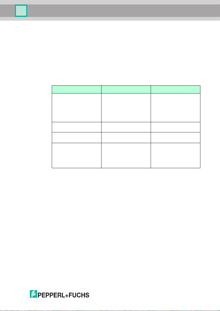
Checklist
Fault Cause Remedy
"PWR" LED does not light upThe power supply is
"PWR" LED does not light upWiring fault in the splitter or
No connection to the
device
No connection to the
device
switched off.
switch cabinet.
Network cable not
connected.
Wrong network cabl e used. Direct connection betw een
Check whether there is a
reason why the power
supply is switched off
(installation or
maintenance wo rk, etc.).
Switch on the power supply
if appropriate.
Check the wiring carefully
and repai r any w iring faul ts.
Connect the network cable.
PC and device: use a
crossover network cable.
Connection via an existing
network: use a twis ted-pair
network cable.
■ If none of the above corrects the problem, please contact the Service
Center. Please have the fault pattern s and version numb er of the senso r
available. The version number can be found at the bottom left of the user
interface.
2015-0 7
57
Page 58
OPC / OPD / OPE
Host
computer
Sensor
parameters (XML-based)
Commands (XML-based)
Results (XML-based)
Data (picture)
Firmware update
Appendix
11 Appendix
11.1 Network Interface
The ne twork interface is used to transfer data (parameters, ima ges, so ftware
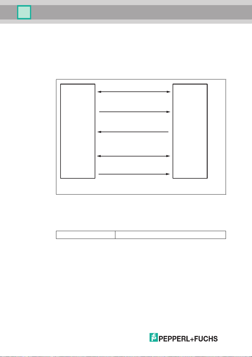
updates) and co mmands in both directions (host to sens or, and sensor to host).
XML strings are used to transfer parameters, comma nds, and results.
Figure 11.1 Network interface XML-Stings
Comm unication is via TCP/IP using port 50005. The default IP address is
192.16 8.2.3.
Each data packet consists of a p reheader and the actual data:
Preheader (length: 12 bytes) Data (len gth varies)
11.2 Software Interface
A .NET 2.0-based software interface is provided for easy integration with PC
software. This software interface takes the form of DLLs and handles the
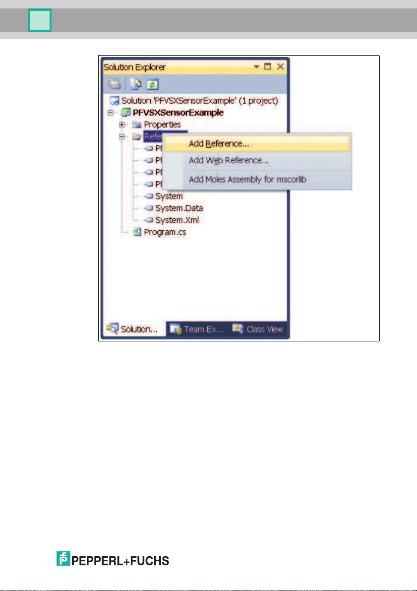
communication with the sen sor. Integrate the DLLs into the programming
environment an d run the programming lines indicated.
58
2015-0 7
Page 59
OPC / OPD / OPE
Appendix
Figure 11.2 Integrating DLLs into the programming environment
All t he examples relate to the Visual Studio 2010 pro gramming environment and
to the C# programming language.
2015-0 7
59
Page 60

OPC / OPD / OPE
Appendix
Example!
Below is a samp le pro gram for integrating and trigger ing the senso r:
class Program
{
static void Main(string[] args)
{
PF.Foundation.VsxFactory.PFVsxFactoryVCCustom sensor;
sensor = new
PF.Foundation.VsxFactory.PFVsxFactoryVCCustom();
sensor.Connect("192.168.2.3", 50005);
sensor.SetSpecificSingleParameter(1, "Command",
"TriggerStart", "1");
System.Threading.Thread.Sleep(1000);
sensor.Disconnect();
}
}
General
The library is used to support the creation of a graphic user interface for sens ors
that use the VSX protocol. The library connects to the senso r and handles the
communication in accordance with the protocol. The user has funct ions for setting
parame ters on the sensor, retrieving para meter values from the sensor, and
saving and loading whole parameter sets both locally and on the sensor. The user
can also receive senso r images.
The library is implemented in C# and requires .NET 2.0 or higher a s a minimum.
Make su re that the libraries supplied are in the project's execu tion folder.
Creating an Object
Create an object to ac cess the library func tions.
PFVsxFactoryVCCustom _vsxFactory =new
PFVsxFactoryVCCustom();
Retrievin g Parameter Data
Received parameter data is stored as a list in the sens or. Individual items of
parame ter data fro m this list can be retrieved using the followin g function:
string GetSpecificSingleParameter(string version, string
configId, string parameterId)
Displaying M odified Data
If data is b eing received by the s ensor, this is indicated by the event:
event ParameterDataReceived(DataModifier modifier)
60
2015-0 7
Page 61

OPC / OPD / OPE
Appendix
2015-0 7
Library Functions
boo l Connect(s tring ip,int por t)
ip: IP of the connec ted sensor
port: Port of the co nnected sensor
Response: Fals e if the connection coul d not b e created, otherw ise true
Opens a connec tion to a sensor with the IP and port specified.
voi d Disconnec t()
Disconnects the open con nection
boo l Connected {get;}
Response: Returns the connection status
voi d SaveSenso rSettings()
Saves the current parameter set in the senso r's memory.
After a confirmation has been received from the sens or, a
SaveDataOnS ensorReceived event is triggered.
voi d LoadSenso rSettings()
Requests a parameter set that has b een saved with S aveSensorSetting s
from the sensor.
After the parameter set has b een received from the sensor, a
ParameterDa taReceived event is triggered with Modifier = LOAD_Dat a.
The data c an then be retrieved using the GetSi ngleParamet er method.
voi d GetNetwor kSettings()
Requests the sensor's cur rent connection settings from the sensor.
After this data has be en received from the sensor, a GetNetworkReceived event
is triggered. Thi s provides the current IP address, network mask, and gateway
for the sensor.
voi d GetLogMes sages(bool on)
on: Switches log mess ages on
off: Swit ches log messages of f
Defines whether or not the sens or send s log me ssages. If log messages are
switched on, a LogDataRe ceived event is tr iggered each time a log message
is received from the senso r.
voi d GetAllPar ametersFromSenso r()
Requests the current parameter set from the sensor. After the parameter set has
been received from the sensor, a P arame terDataRece ived event is triggered
with Modif ier = None. This indicates that the internal list has been upda ted
with the parameter set. You can then retrieve individ ual parameters via
GetSinglePa rameter.
pub lic bool Ex istsParameter(st ring configId, str ing paramet erId)
Used to query whether a particular parameter exists on th e sensor
configId: Configuration ID of a parameter
parameterId : Parameter ID of a parameter
Response: True or false, depending on whether the parameter exists
str ing GetSpec ificSingleParame ter(ushort version , string
con figId, stri ng parameterId)
configId: Configuration ID of a parameter
parameterId : Parameter ID of a parameter
Response: The current value of the s pecified param eter
Retrieves the current value for a parameter from the senso r; details of the
version, configId, and par ameterId can be taken from the ac companying table.
Returns the value of the parameter, or an empty string if the value was not
retrieved.
61
Page 62

OPC / OPD / OPE
Appendix
void SetSpe cificSingleParamet er(ushort versio n, str ing c onfigId,
string para meterId, string newValue)
public bool ExistsResultPar ameter(ushort fram eCounter, s tring
configId, s tring parameterI d)
string GetR esultParameter(u short frameCounter , string co nfigId,
string para meterId)
Bitmap GetI mage(ushort fram eCounter)
IList<Eleme ntResult> GetRes ultList(ushort fra meCounter)
IList<Eleme ntShapeBase> Get Shapes(ushort fram eCounter)
void ResetS ensor()
configId: Configuration ID of a parameter
parameterId : Parameter ID of a para meter
newValue: New value for the parameter
Sets the val ue for a parameter to newValue; versi on, configId, and param eterId
can be taken from the table in this case.
frameCounte r: Numb er of the image associated with the result parameter
configId: Configuration ID of a parameter
parameterId : Parameter ID of a para meter
Response: True or false, depending on whether the parameter exists
Used to query whethe r a parti cular resul t parameter exis ts for a par ticular image.
configId: Configuration ID of a parameter
parameterId : Parameter ID of a para meter
Response: The current value of th e specified parameter
Returns the value of an indiv idual parameter defined by the configuration ID and
parameter ID. The value is taken from an internal list and corresp onds to the
status las t received from the sensor.
The recei pt of result data for a par ticular image is indicated by the
SensorResul tDataReceived(us hort frameCounter) event.
frameCounte r: Numb er of a received i mage
Response: The image associated with the image number
Returns an image previously received from the sens or. Receipt of an image with
a parti cular number i s indicated by the Ima geReceived(ushort
frameCounte r, Bitmap image) event.
frameCounte r: Numb er of the image associated with the graphic s
Response: List of overlay graphics for the spec ified image
frameCounte r: Numb er of the image associated with the graphic s
Response: List of overlay graphics for the spec ified image
Returns a list of graphics for an im age overlay. Receipt of these graphics is
indicated by the ShapeDataRec eived(ushor t frameCounter,
List<IEleme nt> shapeList) event. The indivi dual elements in the list are
of the ElementSh apeBase type.
This class has the follow ing attributes:
PointF Shap eLocation: Coordinates o f the top left corne r of the graphic i n
the image
Color ForeC olor : Col or of the graph ic
string Type : Type of graphic, ei ther type ="Rectangle" or type="Text".
Depending on the type, the graphic can be parsed in
ElementShap eRectangle or Elemen tShapeText an d then has the
following additio nal attributes:
ElementShap eRectangle:
Size Size: The size of the rectangul ar graphic
ElementShap eText:
stringText: The text in the text graphi c
Resets all the sens or's parameters to their factory default settings. After a
confirmation has been received from the sensor, a Parameter DataReceived
event is triggered with Modifier = LOAD_DEFAULT_DATA .
62
2015-0 7
Page 63

OPC / OPD / OPE
Appendix
voi d SaveSetti ngsToFile(string filename)
boo l SetAllPar ameters(string f ilename)
voi d SetNetwor kSettings(string·ipAddr ess, string netw orkMask,
str ing gateway )
voi d SendImage (Bitmap image)
voi d SendVsxFi le(string filepa th)
str ing SensorN ame { get; }
flo at SensorVs xVersion { get; }
Saves the current parameter set to the specified file. The current param eter set is
retrieved from the sensor and saved after receipt. After a successful save, a
SaveDataOnH dd event is triggered. If an error occurs during a save, an
InternalErr or event is triggered wi th ErrorType = SAVE_FIL E_ERROR.
filename: Valid path and file name
Loads a parameter set from the sp ecified fi le and s ends the parameters to the
sensor. After the sens or has a cknowled ged receipt of the parameter s et, a
ParameterDa taReceived event is triggered with Modifi er = NONE. I f the
data set cannot be l oaded co rrectl y, an InternalEr ror event is triggered with
ErrorType = LOAD_FILE_ERROR .
filename: Valid path and file name
ipAddress: Valid IP ad dress
networkMask : Valid network mask
gateway: Valid gateway
Converts the network p arameters on the se nsor. The connection to the sensor is
then disconnected and a Di sconn ectReceived event is triggered. The
connection must be reestablished with the new IP via Connect .
Sends an image to the sensor. This function is not supp orted by all devic e types.
image : Image to be sent
filepath: Path and file name of a valid VSX file
Sends the content of a file to the sens or. This mus t com ply with the VSX
standard. If the d ata cannot be loaded properly or does not correspond to the
VSX syntax, an In terna lError event wi th Error Type =
LOAD_FILE_E RROR is triggered.
Returns the name of the sensor.
Returns the VSX versi on insta lled on the sensor.
Library Events
eve nt Paramete rDataReceived(Da taModifier modifie r)
This is al ways trigg ered if parameter da ta has been received from the sensor.
This is t he case after the following function c all:
LoadSensorS ettings·(MOD IFIER = LOA D_DATA)
GetAllParam etersFromSensor·(MODIFI ER = NONE)
SetSinglePa rameter·(MOD IFIER = NON E)
ResetSensor ·(MODIFIER = LO AD_DEFAULT_ DATA)
SetAllParam eters ·(MODIFIER = NONE)
Whenever this event is trigger ed, the internal list of par ameters has been
updated and the individual param eter values should be retrieved with
GetSinglePa rameter.
eve nt SensorRe sultDataReceived (ushort framecount er)
This is t riggered when result data is received from the senso r. The parameter is
an imag e numbe r that allows the data to b e assigned to the corres ponding
image. The individual results data can be retrieved with
GetResultPa rameter.
2015-0 7
63
Page 64

OPC / OPD / OPE
Appendix
event Singl eDataReceived(st ring configId, str ing paramet erId,
string valu e)
event Accep tReceived()
event Senso rInformationDataRe ceived(string ty pe, st ring version,
string macA ddress)
event Disco nnectReceived(st ring errorMessage)
event SaveD ataOnSensorRecei ved()
event GetNe tworkReceived(st ring ipAddress, st ring mask, string
gateway)
event LogDa taReceived(strin g logData, LogMess ageTypes lo gType)
event Shape DataReceived(ush ort frameCounter)
The following event is supported by lase r triangulation sensor s only:
event LineD ataReceived(usho rt frameCounter, L ineMulti li nes,
ushort stat us)
event Image Received(ushort frameCounter)
event SaveD ataOnHddReceived ()
event Error Received(string id, string name)
This is triggered after S etSin gleParamete r if this one value o nly has b een
changed on the sensor.
This is triggered after S etSin gleParamete r if the value previous ly set has
been successfull y changed on the sensor.
This is triggered when any data is received from the sensor. Details of the sensor
type, its fi rmware vers ion, an d its MAC a ddress are transmitted.
This is triggered if the co nnection is not disconnected with Disconnect. A
description of the reason for the lost connection is transmitted.
This is triggered after the SaveSens orSet tings function has been called
successfully.
This is triggered after the data requested from the sen sor with
GetNetworkS ettings has been received. The IP addr ess, the network mask,
and the sensor 's gateway are transmitted.
This is triggered when log data has been recei ved from the sensor. The data and
log data type are transmitted as parameters.
This is triggered when graphics for the image over lay have been received. The
image number specifies the image with whi ch the graphics are associated. A lis t
of all g raphics can then be retrieved using the Get Shapes(usho rt
frameCounte r) function.
This is triggered when line data has been received from the sensor. In additio n to
the line data, the image number is issued s o that the da ta can be assig ned to the
appropriate imag e. A status is issued that refle cts the sens or's hardware inputs
and ou tputs.
This is triggered when an image has be en received from the sensor. The image
number is transmitted as a parameter. The image can then be retrieved us ing the
GetImage(us hort frameCounte r) function .
This is trig gered when the current parameter set has been s uccessfully saved to
a file.
This is triggered when an error has occurred in the senso r software. The
parameters contain more details about this error.
64
2015-0 7
Page 65

OPC / OPD / OPE
Appendix
eve nt Internal Error(ErrorTypes errorType, string errorMessa ge)
enu m·Error Types{ INVALID_D ATA_RECEIVE D, SAVE_FILE_ERR OR,
LOA D_FILE_ERRO R, PARAMETER_NOT _FOUND }
enu m·DataM odifier{ NONE, L OAD_DATA, L OAD_DEFAULT_DATA }
enu m LogMessag eTypes { DEBUG, INFO, RESULT_OK, R ESULT_NOT_O K,
WAR NING, ERROR , CRITICAL, ASSE RT }
This is t riggered when an internal error has occurred. This happens in the
following cases:
■ When calling GetS ingleP arame ter (ErrorT ype =
PARAMETER_NOT_FO UND) if the required parameter has not been found in
the internal list
■ When calling SetS ingleP arame ter (ErrorT ype =
PARAMETER_NOT_FO UND) if the parameter to be set is not present
■ When calling Save Settin gsToF ile (ErrorT ype =
SAVE_FILE_ERROR) if the parameter data could not be saved to a file
■ When calling Load Settin gsFro mFile (Erro rType =
LOAD_FILE_ERROR) if the parameter file could not b e loaded
■ When calling SetA llPara meter s (ErrorTyp e = LOAD_FILE_ERRO R)
if the parameter data could not b e loaded from the file or if the file contains
invalid data
■ In all cases where Para meter DataReceive d or
SensorResultData Received would be triggered but the sensor data
received is incorrect ( ErrorType = INVALI D_DATA_RECE IVED).
■ If log data is received from the sens or but this is incorrect (ErrorType =
INVALID_DATA_REC EIVED)
■ When calling Send VsxFil e (Er rorType = L OAD_FILE_ERROR) if the
file cannot be loaded or does not correspond to the VSX syntax
The error Message parameter contains a mo re detailed des cription of the
respective error.
See Inter nalErr or event.
See Param eterDa taRec eived event.
See LogDa taRece ived event.
2015-0 7
65
Page 66
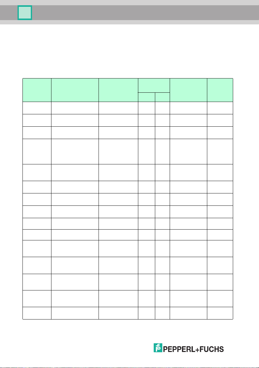
OPC / OPD / OPE
Appendix
11.2.1 Configuration Over view
The parameters in the table below can be set using the
SetSpecificSingleParameter and GetSpecificSingleParameter
method in the software interface. Each parame ter is identified by a con figID and a
parame terID.
Configu ration Parameters
Config
Config
ID Parameter ID Value
System EnableRS -232 0, 1 1 Enables RS-
DataSize 5, 6, 7, 8 1 RS-232 data
StopBits 1, 2 1 RS-232 stop
BaudRate BAUD_11 5200
ParityMod e PARITY_EV EN
Trigger String string 1 R S-232 trigger
EnableResultPort 0, 1 1 Enables TCP/IP
UDP 0, 1 1 Enables UDP
PortOut 1 ... 65536 1 TCP port 5415
BAUD_19 200
BAUD_38 400
BAUD_57 600
BAUD_96 00
PARITY_NONE
PARITY_ODD
Version
Desc ription
232
size
bits
1 R S-232 baud
1 R S-232 check
rate
bit
string
result
result
From
Firmware
Versionfrom to
5415
5415
5415
5415
5415
5415
5415
5415
66
PortOutU dp 1 ... 65536 1 U DP po rt 5415
PosLeds 0, 1 1 S witches
Enable VGA 0, 1 1 O PE only:
PulseLengthGOOD 1 ... 1000 1 Pulse length in
PulseLengthBAD 1 ... 1000 Pulse length in
SensorName string 1 Customizab le
positio n LEDs
on or off
Switches VGA
outp ut on or off
ms for GOOD
outp ut signal
ms for BAD
outp ut signal
string
6106
8738
8474
8474
8470
2015-0 7
Page 67
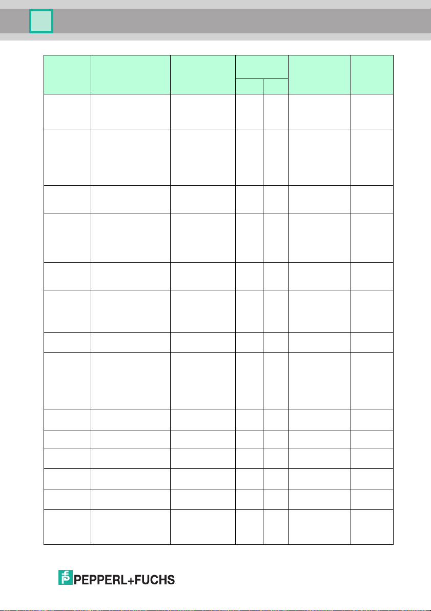
OPC / OPD / OPE
Appendix
Config
Config
ID Parameter ID Value
ImageFormat 75 2x480
ImageFinePosition -50 ... +50 1 If th e imag e
ImageTransfer ALL_IMG
ImageTransferActive 0, 1 1 Enables or
ImageBuffer ALL_IMG
OverwriteBuffer 0, 1 1 Overw rites the
Camera Flas hTime 0 ... 255 1 Sets the flash
Gain 0 ... 255 1 Sets the image
Command TriggerStart 1 1 Triggers an
BlockTrigger 1 1 Blocks triggers 5971
752x240
752x160
752x120
ERRO R_IMG
GOOD_IMG
ERRO R_IMG
GOOD_IMG
Version
Description
1 Image capture
1 Selects images
1 Which im ages
area that is
captu red and
processed
format has less
than 480 lines:
vertical line
offset r elative to
the center of the
imag e
to transfer to th e
connected PC
disables
transmission of
VSX image
information after
each cycle
are to be saved
imag es in the
memor y when
the memory is
full
time in ms
captu re time in
ms. The
AutoEx posure
selection field
must be
disabled
imag e capture
From
Firmware
Versionfrom to
6022
8597
7818
6064
7818
8473
5415
5415
5930
ResetCounter 1 1 Resets the
GetLastImg 1 1 Req uests the
GetErrImg 1 1 Requests the
SetDefaul tParams 1 1 Sets the
2015-0 7
counter
current image
last fau lt pattern
parameters to
the factory
settings
8578
5415
5415
7900
67
Page 68
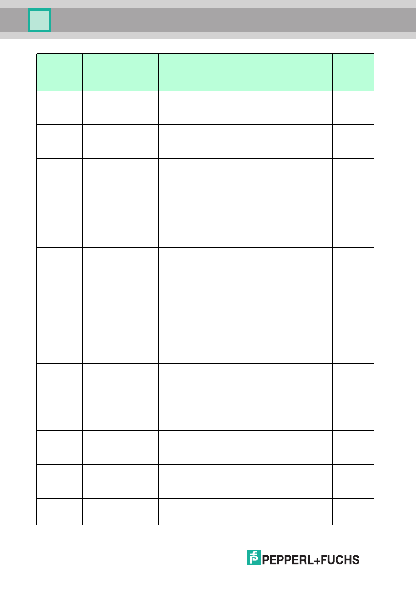
OPC / OPD / OPE
Appendix
Config
ID Parameter ID Value
Trigger
Modes
Trigger Mode TRIGGER_DIRE
DirectMode TRIGGER_DIRE
EdgeMode TRIGGER _EDG
ContinueConn ect 0, 1 1 In DirectM ode
LvlTrigCycle 8 ... 1000 1 Cycle time in
CreateDebugImage 0, 1 1 Creates and
EncoderResolution 100 ... 3000 1 OPC and OP D
Trigger Offset 0 ... 32767 1 OPC and OP D
TargetDistance 70 ... 200 1 OPC only:
SheetLength 100 ... 300 1 O PC and OPD
CT_MOD E
TRIGGER _ENC
ODER_M ODE
CT_EDGE
TRIGGER _DIRE
CT_LEVEL
E_POS
TRIGGER _EDG
E_LEVE L
Config
Version
Desc ription
1 Sets the trigger
1 Sets the trigger
1 Sets the trigger
operating mod e
signa l
characteristic s
signa l polarity
Rising or falling
edge in
DirectMode =
TRIGGER_DIR
ECT_EDGE
High level or low
level in
DirectMode =
TRIGGER_DIR
ECT_LEVEL
operating mod e
=
TRIGGER_DIR
ECT_LEVEL:
trigg er repeated
when VSX
connection
active
DirectMode
operating mod e
=
TRIGGER_DIR
ECT_LEVEL
sends a fault
pattern
only: number of
increment
widths per
meter
only: offset o f
the fir st trigger
in mm
distance of the
object from the
sensor in mm
only: length of
the sheet in mm
From
Firmware
Versionfrom to
5783
6022
6022
7818
7869
6064
5988
5988
5988
5988
68
2015-0 7
Page 69
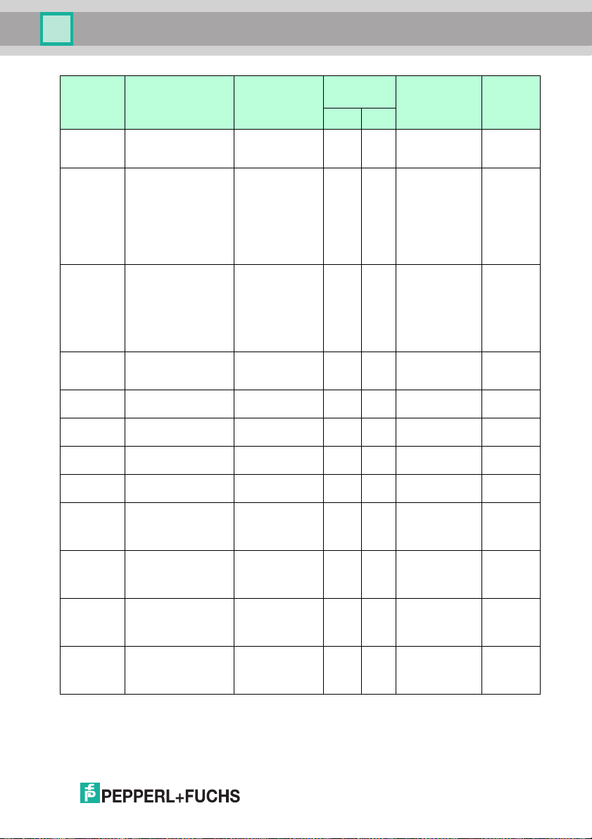
OPC / OPD / OPE
Appendix
Config
ID Parameter ID Value
DistanceTolerance 0 ... 20 1 OPC and OPD
Wind ow N
N = 1, 2, 3,
4
MoveDirection
ResetCycle 1 1 OPC and OPD
WinActive 0, 1 1 Window N
XStart 0 ... 751 1 X c oordinate for
YStart 0 ... 479 1 Y coordinate for
RoiWidt h 1 ... 752 1 W indow width
RoiHeight 1 ... 480 1 Wind ow height
XStart_Pattern 0 ... 751 1 X coordinate for
YStart_Pattern 0 ... 479 1 Y c oordinate for
RoiWidt h_Pattern 64 , 128, 196,
RoiHeight_Pattern 64, 128, 196,
MOVE _HOR_N
EGATIVE
MOVE _HOR_P
OSIT IVE
MOVE _VER_N E
GATIVE
MOVE _VER_P O
SITIVE
256
256
Config
Version
Description
only: tolerance
for slippage
1 OP C and OPD
1 Pattern
1 Pattern
only: direction of
movement of
sensor
only: resets an
initiated cycle if
Trigger Mode
operating mode
=
TRIGG ER_ENC
ODER _MODE
enabl ed/disable
d
window (ROI)
window (ROI)
(ROI)
(ROI)
pattern
comparison
window
pattern
comparison
window
comparison
window width
(ROI)
comparison
window heig ht
(ROI)
From
Firmware
Versionfrom to
5988
5988
5988
5415
5415
5415
5415
5415
5415
5415
5415
5415
2015-0 7
69
Page 70
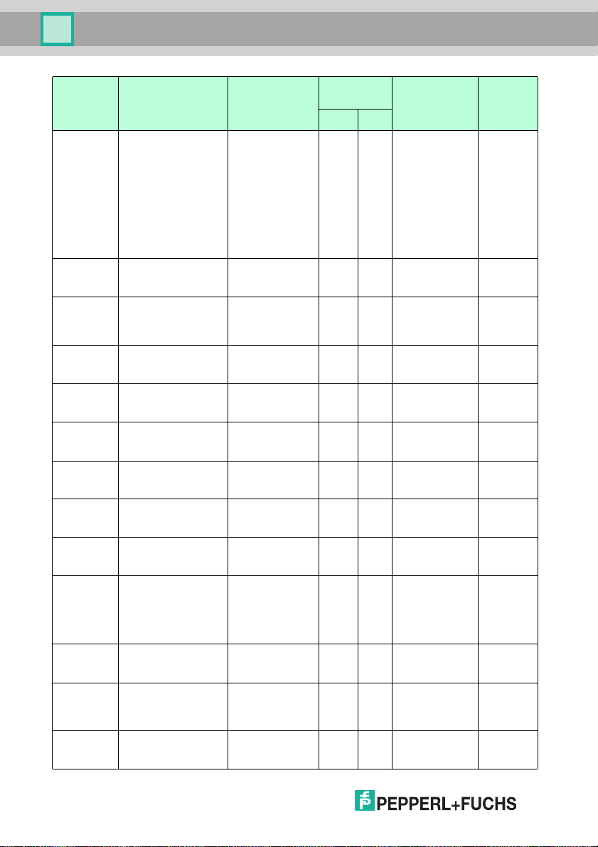
OPC / OPD / OPE
Appendix
Config
ID Parameter ID Value
Inspec tionTask INSPECTION_T
CheckD ataMatrix 0, 1 1 E nables or
CheckInterleaved2of50, 1 1 Enables or
CheckC ode128 0, 1 1 Enables or
CheckC ode39 0, 1 1 E nables or
CheckC ode13 0, 1 1 E nables or
CheckP harma 0, 1 1 Enables or
MinCodeLen1D 0 ... 255 1 Inputs the
CheckS uml25 0, 1 1 E nables or
Suppre ssDuplicates 0, 1 1 E nables or
MatchString string 1 String for
UpdateM atchString 1 1 Transfers Match
CheckC heckPosition 0, 1 1 Position check
70
YPE_1_DECOD
E_1D2D
INSPECTION_T
YPE_2_MATCH
_1D2D
INSPECTION_T
YPE_3_MATCH
_LOGO
INSPECTION_T
YPE_4_PRESE
NCE_CHECK
Config
Version
Desc ription
1 Sets the
inspection type
disables Data
Matrix
disables
Interleaved 2 of
5
disables
Code128
disables
Code39
disables
Code13
disables
Pharmacode
minimum code
length
disables
checks um test
disables
suppression of
consecutive
codes with
identical content
reading
matches
String from last
succe ssful
reading
enab led for
barcodes
From
Firmware
Versionfrom to
5415
5415
5415
5415
5415
5415
5415
7892
5716
7892
5415
5716
5422
2015-0 7
Page 71
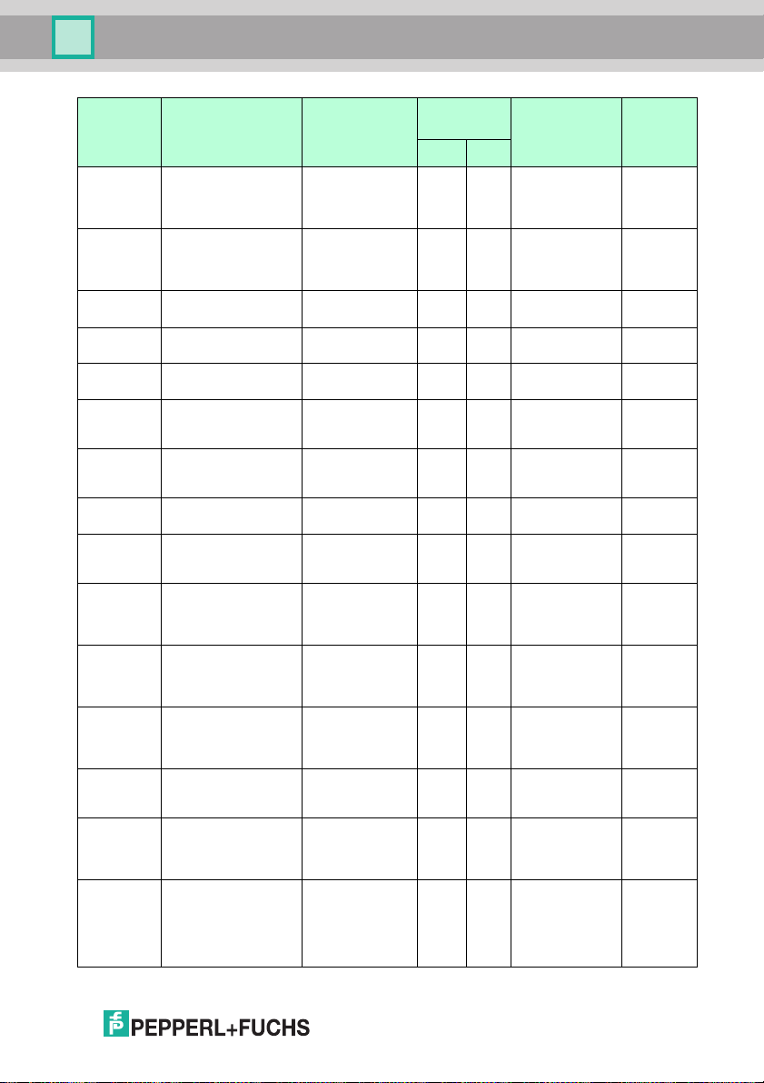
OPC / OPD / OPE
Appendix
Config
ID Parameter ID Value
deltaX 0 ... 752 1 Horizontal
deltaY 0 ... 480 1 Vertical
PresenceE dgeThres
hold
PresenceE dgeFilter
Width
PresenceE dgeRatio
Min
PresenceE dgesHoriz
ontal
PresenceE dgesVerti
cal
PresenceInvertOut 0, 1 1 Inverted
PresenceE dgeImage 0, 1 1 Shows edge
DataMatrixInvers INVE RS_autoCh
DataMatrixMirror M IRROR_autoC
Orientation 0 ... 7 1 Permitted
Timeout1D2D 0 ... 65534 1 Timeout for 1-
TimeoutMatch1D2D 0 ... 65534 1 Timeout for 1-
GoodString string 1 Output s tring
0 ... 255 1 Edge thres hold 8102
1 ... 5 1 E dge filter width 8102
0 ... 2000 1 E dge quotient 8102
0, 1 1 Enables/disable
0, 1 1 Enables/disable
ang e
INVE RS_off
INVE RS_on
hang e
MIRROR_off
MIRROR_on
Config
Version
Description
tolerance for
position check
for barcodes
tolerance for
position check
for barcodes
s horizontal
edge calculation
d vertical edge
calculation
evaluation logic
imag e in original
imag e
1 D ecoding
1 D ecoding
process for
inverse Data
Matrix codes
process for
mirrore d Data
Matrix codes
orientations of
the Data Matrix
code
D/2-D decoding
processes
D/2-D decoding
processes
(match)
from goo d read;
can contain
placeholders for
inspection
information
From
Firmware
Versionfrom to
5415
5415
8102
8102
8102
8102
7892
7892
8597
5415
5415
8349
2015-0 7
71
Page 72
OPC / OPD / OPE
Appendix
Config
ID Parameter ID Value
BadString string 1 O utput string
Table 11.1 Configuration p arameters
11.2.2 Resu lt over view
Accessing the result data
The sensor transmits result data in the following situations:
■ After transferring eac h image
■ Trigger
■ Counter value req uest ( "ShowCounter ")
The result data is contained in the CONFIGURATION Id=“Result” node. The
node co ntains two different result parameters depending on the situation.
■ Result data (PF.Foundation.Protoco l.XML.ElementResult)
■ Shape data (PF.Foundation.Protocol.XML.ElementShap eBas e)
The result data is exclusively text data, which is transmitted in barcode mode and
after Teach-in. Th e sha pe consists of either geometrical shapes, such as color ed
rectangles (ElementShapeRectangle), or a type label (E lementShapeText).
Result data
The result data is transmitted with the SensorResultDataReceived event and
can be retrieved in the event hand ler us ing the GetResultList and
GetResultParameter method.
The following event and p arameter IDs are per mitted:
Config
Version
Desc ription
from bad read ;
can contain
placeholders for
inspection
information
From
Firmware
Versionfrom to
8349
72
2015-0 7
Page 73
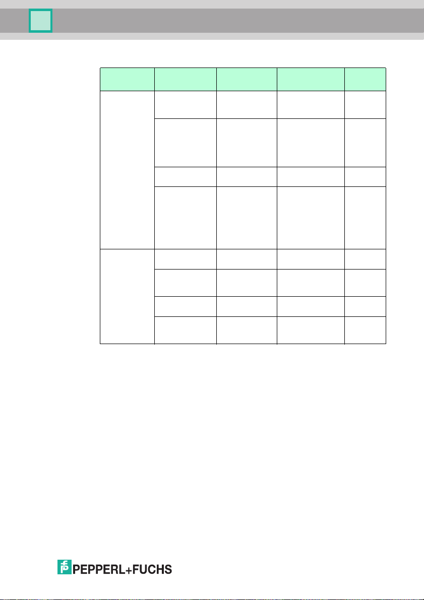
OPC / OPD / OPE
Appendix
Result data
Event Par ameter ID Value Description
Trigger R esWx Wind ow x:
ResWx Type DataMatrix
ResxTime 0 ... 65535 ms Window x:
ResxQual 0 ... 100%/
Show Counter CtrCaptured 0 ... Number of
CtrLogoMatch 0 . .. N umber of
CtrFailedRead 0 ... N umber of failed
CtrFailedMatch 0 ... Number of
Table 11.2 Result data
Code128
Code39
EAN/UPC/JAN
2/5 Interleaved
Pharmacode
0 ... 100%
barcode content
(decoded string
Wind ow x:
barcode type
Decod ing time
Wind ow x:
Location quality
horizontal/verti cal;
100%/100%
means barcod e is
exactly in the
center of the
image
captu red images
succes ful logo
comparison s
decodi ngs
mismatched
decodi ngs
From
Firmware
8597
8597
8597
8597
8606
8606
8606
8606
2015-0 7
73
Page 74
OPC / OPD / OPE
Appendix
Shape data
The shape data is transmitted with th e ShapeDataReceived and
ImageDataReceived events. The GetShapes method is used to retrieve the
data.
The following parameters are transmitted:
Shape data
Type Parameter ID Wert Beschreibung A b Firmware
Eleme ntShape
Text
Eleme ntShape
Rectangle
Table 11.3 Shape data
Resx Window x:
ResxTime 0 65535 m s Window x:
Readx Window x:
Barcode
content
(decoded
string)
Decodi ng time
Bounding box
around
barcod e
8597
8597
8597
74
2015-0 7
Page 75

Sub ject to modificatio ns
Cop yright PEPPERL+FUCH S • Print ed in G ermany
www.pepperl-fuchs.com
FACTORY AUTOMATION –
SENSING YOUR NEEDS
Worldwide Headquarters
Pepperl+Fuchs GmbH
68307 Mannheim · Germany
Tel. +49 621 776-0
E-mail: [email protected]
USA Headquarters
Pepperl+Fuchs Inc.
Twinsburg, Ohio 44087 · USA
Tel. +1 330 4253555
E-mail: [email protected]
Asia Pacific Headquarters
Pepperl+Fuchs Pte Ltd.
Company Registration No. 199003130E
Singapore 139942
Tel. +65 67799091
E-mail: [email protected]
TDOCT-2828C ENG
07/2015
 Loading...