

Page 1
ISO9001
MANUAL
Warning Device
NVD-111
PROCESS AUTOMATION
Page 2

Warning Device NVD-111
With regard to the supply of products, the current issue of the following document is applicable:
The General Terms of Delivery for Products and Services of the Electrical Industry, published by
the Central Association of the Electrical Industry (Zentralverband Elektrotechnik und
Elektroindustrie (ZVEI) e.V.) in its most recent version as well as the supplementary clause:
"Expanded reservation of proprietorship"
Page 3

Warning Device NVD-111
EN
Contents
1 Safety................................................................................... 2
1.1 General safety instructions ...........................................................................2
1.2 Used Symbols...............................................................................................2
1.3 Declaration of Conformity .............................................................................3
1.4 Intended Use ................................................................................................3
1.5 Maintenance.................................................................................................4
1.6 Delivery, Transport and Storage ...................................................................4
1.7 Installation and Commissioning ....................................................................4
1.8 Operation......................................................................................................5
1.9 Repair...........................................................................................................5
1.10 Disposal........................................................................................................5
1.11 Applied Standards and Directives.................................................................5
2 Product Specifications ...................................................... 6
2.1 Function........................................................................................................6
2.2 Product Program...........................................................................................7
2.3 Design and Dimensions................................................................................8
3 Installation ........................................................................ 12
3.1 Mounting of the Sensors .............................................................................12
3.2 Mounting the Warning Device.....................................................................20
3.3 Connection .................................................................................................21
4 Commissioning................................................................. 28
4.1 Configuring the Warning Device using DIP Switches..................................28
5 Operation .......................................................................... 32
5.1 Alarm Signals..............................................................................................32
5.2 Resetting the Alarm Signal..........................................................................33
5.3 Function Testing .........................................................................................34
6 Troubleshooting ............................................................... 35
6.1 Troubleshooting and Alarm States..............................................................35
6.2 Sensor Maintenance...................................................................................36
7 Technical Specifications ................................................. 37
7.1 Warning Device NVD-111...........................................................................37
7.2 Overflow Sensor KVF-O .............................................................................38
7.3 Fat Level Sensor KVF-F..............................................................................38
7.4 Fat Level Sensor FAU-104..........................................................................38
266859 2014-04
EN - 1
Page 4
Warning Device NVD-111
EN
Safety
1Safety
1.1 General safety instructions
Responsibility for planning, assembly, commissioning, operation, maintenance,
and dismounting lies with the system operator.
Installation and commissioning of all devices must be performed by a trained
professional only.
Protection of operating personnel and the system is not ensured if the product is
not used in accordance with its intended purpose.
Laws and regulations applicable to the usage or the intended purpose must be
observed. The devices are only approved for appropriate and intended use.
Ignoring these instructions will void any warranty and absolve the manufacturer
from any liability.
The Declaration of Conformity, Certificate of Compliance, Statement of
Conformity, EC-type-examination certificate and data sheets are an integral part
of this document.
The data sheet contains the electrical data of the Declaration of Conformity, the
Certificate of Compliance and the EC-type-examination certificate.
The documents mentioned are available from http://www.pepperl-fuchs.com or
contact your local Pepperl+Fuchs representative.
1.2 Used Symbols
Safety-relevant Symbols
Danger!
This symbol indicates an imminent danger.
Non-observance will result in personal injury or death.
Warni ng!
This symbol indicates a possible fault or danger.
Non-observance may cause personal injury or serious property damage.
Caution!
This symbol indicates a possible fault.
Non-observance could interrupt devices and any connected facilities or systems,
or result in their complete failure.
266859 2014-04
2 - EN
Page 5
Warning Device NVD-111
EN
ISO9001
Safety
Informative Symbols
Note!
This symbol brings important information to your attention.
Action
This symbol indicates a paragraph with instructions.
1.3 Declaration of Conformity
All products were developed and manufactured under observance of the
applicable European standards and guidelines.
Note!
A Declaration of Conformity can be requested from the manufacturer.
The product manufacturer, Pepperl+Fuchs GmbH, 68307 Mannheim, has a
certified quality assurance system that conforms to ISO 9001.
1.4 Intended Use
The warning device is a compact alarm system for monitoring one or two sensors
in grease interceptors.
The warning devices must only be installed in a suitable control cabinet or
NVO5-KV installation housing.
The warning device was designed for:
n the monitoring of the fat layer thickness, i. e. an alarm if a certain limit of
maximum receptacle capacity of fat has been reached.
n the monitoring of the overflow of liquid, e. g. in the event of a blocked drain
266859 2014-04
EN - 3
Page 6
Warning Device NVD-111
EN
Safety
Only the following sensors must be connected to the warning device:
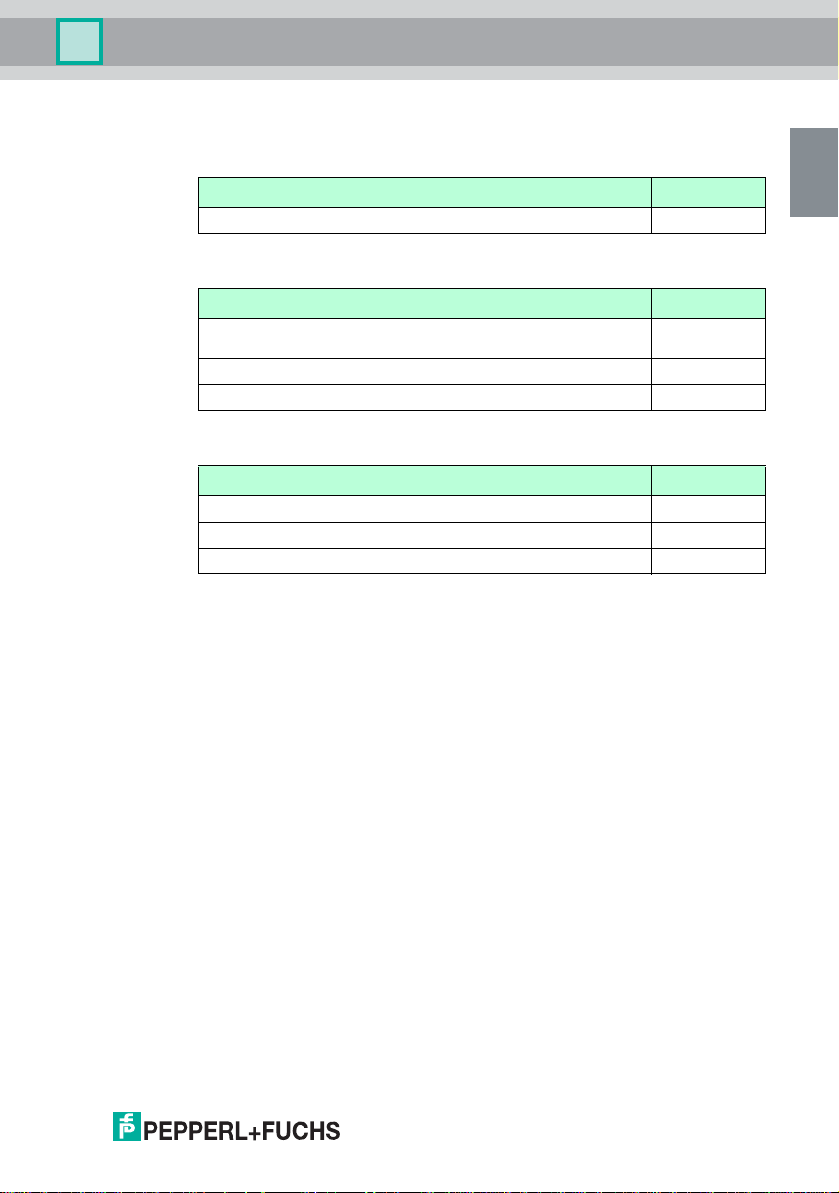
Description Type code
Fat level sensor, for detecting fat layer thickness in an aqueous
emulsion with small lumps of fat or a hardened layer of fat
Fat level sensor, for detecting fat layer thickness in a liquid layer of fat KVF-F
Overflow sensor, for detecting excessively high liquid level KVF-O
1.4.1 Designation
Warning device
Pepperl+Fuchs GmbH
Lilienthalstrasse 200, 68307 Mannheim, Germany
NVD-111
1.5 Maintenance
The device must not be cleaned with caustic fluids.
The devices are maintenance-free. However, to guarantee perfect operation of
the complete alarm system, check the operation, including all sensors, at least
once a year.
1.6 Delivery, Transport and Storage
Check the packaging and contents for damage.
Check if you have received every item and if the items received are the ones you
ordered.
Keep the original packaging. Always store and transport the device in the original
packaging.
Always store the device in a clean and dry environment. The permitted storage
temperature (see data sheet) must be considered.
1.7 Installation and Commissioning
1.7.1 Installation of the warning device
The device must only be installed outside potentially explosive zones. The
device must not be installed in places with potentially aggressive vapors.
The device must be free of voltage during installation and maintenance. The
warning system must only be connected to the supply voltage after complete
mounting and connection of the sensors.
The identification plate must not be removed.
FAU-104
266859 2014-04
4 - EN
Page 7

Warning Device NVD-111
Safety
1.8 Operation
1.8.1 Availability of Emulsion
Grease interceptors are plants which can separate fat from water. It may occur
that fat is not separated due to the emulsion that has formed. An emulsion is a
more or less stable mixture of fat and water. If the water content in the fat is too
high, the sensor does not detect any fat.
1.9 Repair
The devices must not be repaired, changed or manipulated. If there is a defect,
the product must always be replaced with an original device.
1.10 Disposal
Disposal of devices and their packaging material must be performed in
compliance with the applicable laws and guidelines of the corresponding country.
The devices do not contain batteries which need to be disposed of separately
from the products.
1.11 Applied Standards and Directives
EN 50178:1997
EN 61000-6-4:2007
EN 61326-1:2013
EMC Directive 2004/108/EC
Low Voltage Directive 2006/95/EC
EN
266859 2014-04
EN - 5
Page 8

Warning Device NVD-111
EN
Product Specifications
2 Product Specifications
2.1 Function
The warning device monitors the status of
n a fat level sensor or
n an overflow sensor or
n the combination of an overflow sensor and a fat level sensor
in a grease interceptor.
LEDs at the device indicate alarm, sensor fault and system and sensor status. In
the event of an alarm, an additional acoustic signal sounds.
The fat in the grease interceptor can be of various compositions. The following
conditions are possible:
n The fat is liquid. Such fat is found in, e. g., the manufacture and storage of
vegetable fats. This fat forms a liquid fat layer which clearly separates from
water. For this composition of fat, please use fat level sensor KVF-F for
detecting the fat layer thickness.
n The fat is hard. Such fat is found in, e. g., waste water from sinks or
dishwashers and in floor drains in large kitchens or catering
establishments. This fat consists of a mixture of animal and vegetable fats.
It typically forms an aqueous emulsion with small lumps of fat or a
hardened layer of fat. For this composition of fat, please use fat level
sensor FAU-104 for detecting the fat layer thickness.
266859 2014-04
6 - EN
Page 9
Warning Device NVD-111
EN
Product Specifications
2.2 Product Program
Warn ing device
Description Type code
Warning device, 230 V AC NVD-111
Sensors
Description Type code
Fat level sensor, for detecting fat layer thickness in an aqueous
emulsion with small lumps of fat or a hardened layer of fat
Fat level sensor, for detecting fat layer thickness in a liquid layer of fat KVF-F
Overflow sensor, for detecting excessively high liquid level KVF-O
Accessories
Description Type code
Cable connector IP68 for one sensor LAL-SK2
Mounting set for one sensor NVO5-B
Installation housing with DIN mounting rail NVO5-KV
FAU-104
266859 2014-04
EN - 7
Page 10
Warning Device NVD-111
EN
NVD-111
ALARM
RESET
SUPPLY FAT LAYER
ALARM
OVERFLOW
ALARM
SYSTEM
OK
68307 Mannhei m Ge r m a ny
www.pepper l-f uchs. com
Fat Alarm System
70
58
86
54
4
23
5
1
200
116 105
Product Specifications
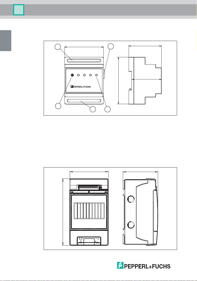
2.3 Design and Dimensions
Warning device NVD-111
Figure 2.1
1 DIP switches
2 LEDs
3 Connections for power supply and potential-free contacts
4 Reset button
5 Sensor connections
8 - EN
Installation housing NVO5-KV
Figure 2.2
266859 2014-04
Page 11
Warning Device NVD-111
EN
Product Specifications
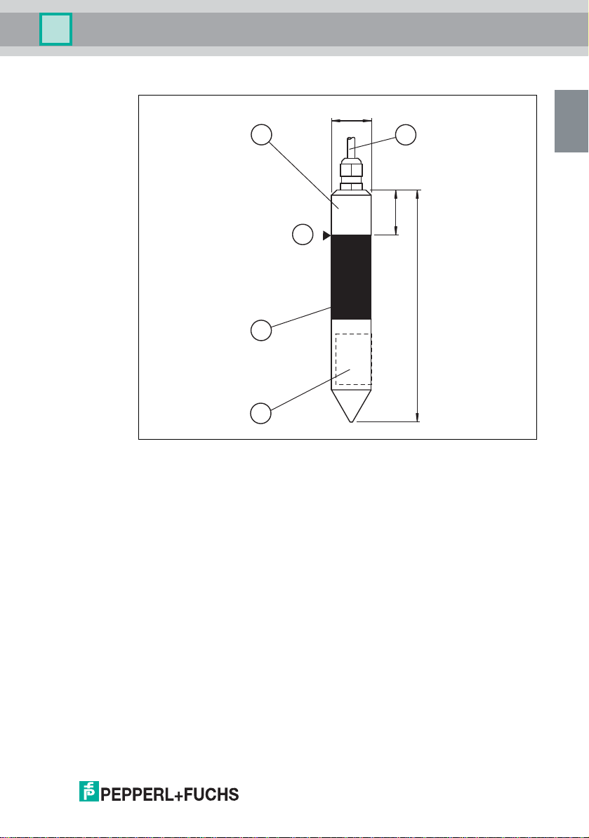
Overflow sensor KVF-O
Ø31.6
3
5
2
1
4
25
138
Figure 2.3
1 Lower section with laser marking
2 Middle section
3 Upper section
4 Cable
5 Switching point
266859 2014-04
EN - 9
Page 12
Warning Device NVD-111
EN
Product Specifications
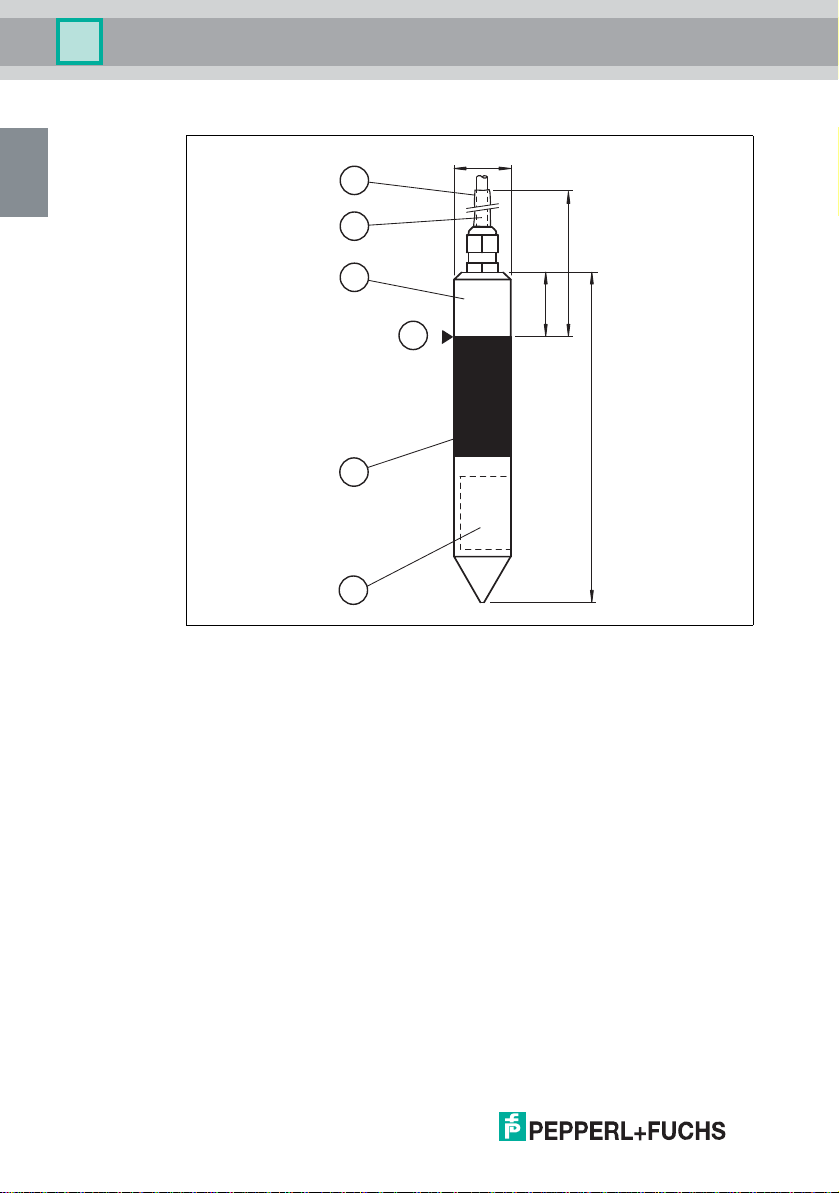
Fat level sensor KVF-F
Ø31.6
5
4
3
2
1
Figure 2.4
1 Lower section with laser marking
2 Middle section
3 Upper section
4 Cable
5 Shrink tubing
6 Switching point
300
25
6
138
266859 2014-04
10 - EN
Page 13
Warning Device NVD-111
EN
4
3
2
1
5
6
152
300
Ø38
66
Product Specifications
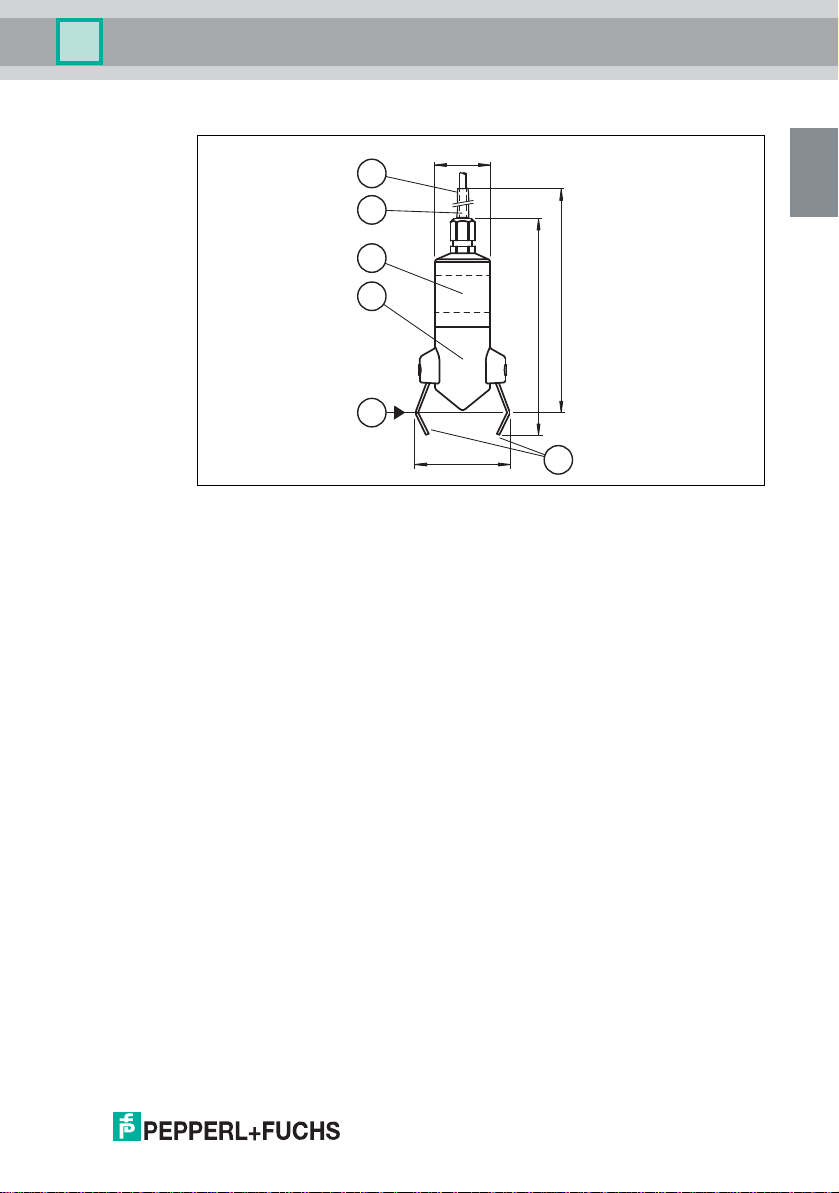
Fat level sensor FAU-104
Figure 2.5
1 Lower section
2 Laser marking
3 Cable
4 Shrink tubing
5 Reflectors
6 Schwitching point
266859 2014-04
EN - 11
Page 14
Warning Device NVD-111
EN
Installation
3 Installation
3.1 Mounting of the Sensors
Read the chapter on Safety and, in particular, the section on Installation and
Commissioning (see chapter 1.7) before mounting the sensor. Do not remove the
identification plate.
Warni ng!
Risk of short circuit
Injuries and damage to the device are possible when working with live parts.
n Before working on the device, always disconnect the supply voltage.
n Connect the device to the supply voltage only after completion of the work.
During installation, read the instructions provided by the grease interceptor
manufacturer. Ensure that the suspension mechanism keeps the sensor
permanently at the correct height. Where possible, secure the device in a position
where it can be reached from the manhole opening so that it can be removed
when emptying (disposal) or carrying out maintenance work on the grease
interceptor.
The oil/petrol separator can be made of various materials. We therefore
recommend using the following methods to secure the device in a suspended
position:
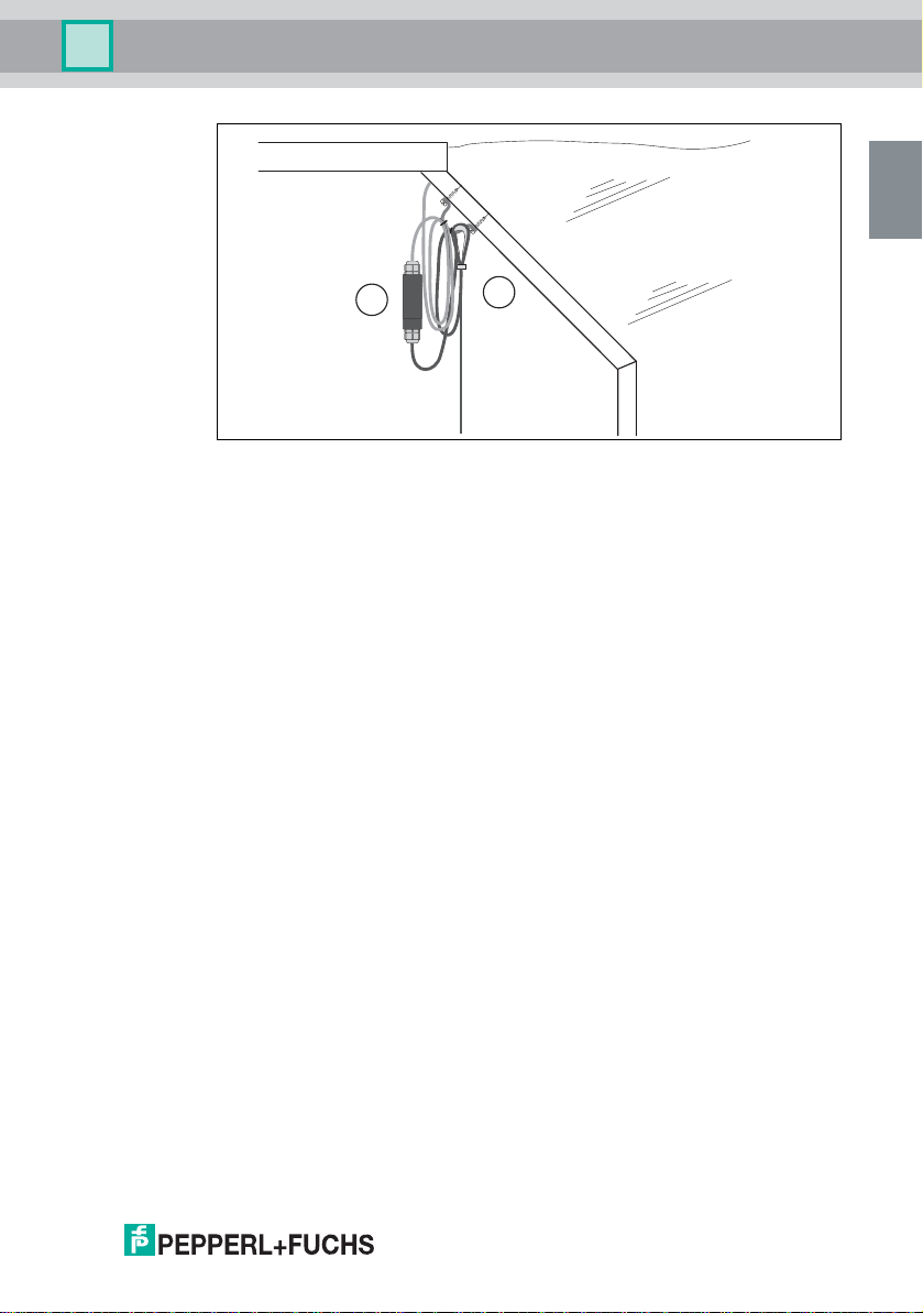
n If mounting the device in concrete containers, use the NVO5-B mounting
set. See the figure below.
n If mounting the device in containers made from other materials, such as
plastic or metal, use other suspension devices as appropriate, for example,
screws and screw anchors.
266859 2014-04
12 - EN
Page 15
Warning Device NVD-111
EN
2
1
Installation
Figure 3.1 Mounting using cable connector and mounting set
1 Mounting set for one sensor NVO5-B
2 Cable connector for one sensor LAL-SK2
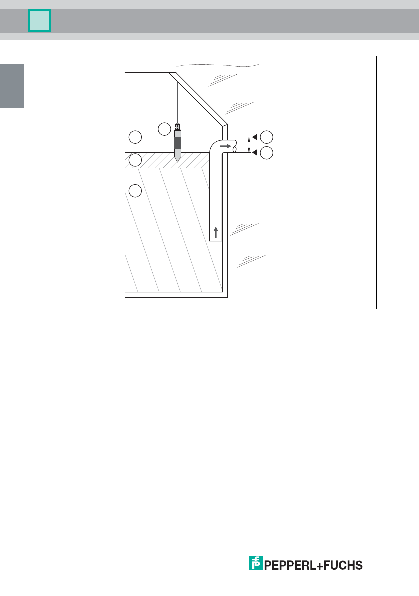
3.1.1 Mounting the KVF-O Overflow Sensor
Usually, the switching point of the sensor must be located a few centimeters
above the normal liquid level (water zero line) in a position so close to the water
zero line that the switching point is surrounded by liquid when an overflow occurs.
This occurs
n when there is back pressure in the sewage system or
n if the drain is blocked.
The switching point of the sensor is located between the insulated connecting
piece and the top metal section (see chapter 2.3).
266859 2014-04
EN - 13
Page 16
Warning Device NVD-111
EN
B
C
A
1
L
S
X
Installation
14 - EN
Figure 3.2 Mounting the overflow sensor
1 Overflow sensor KVF-O
A Air
B Fat, oil, grease (FOG)
C Water
L Water zero line
S Sensor switching point
X Alarm limit (maximum liquid level)
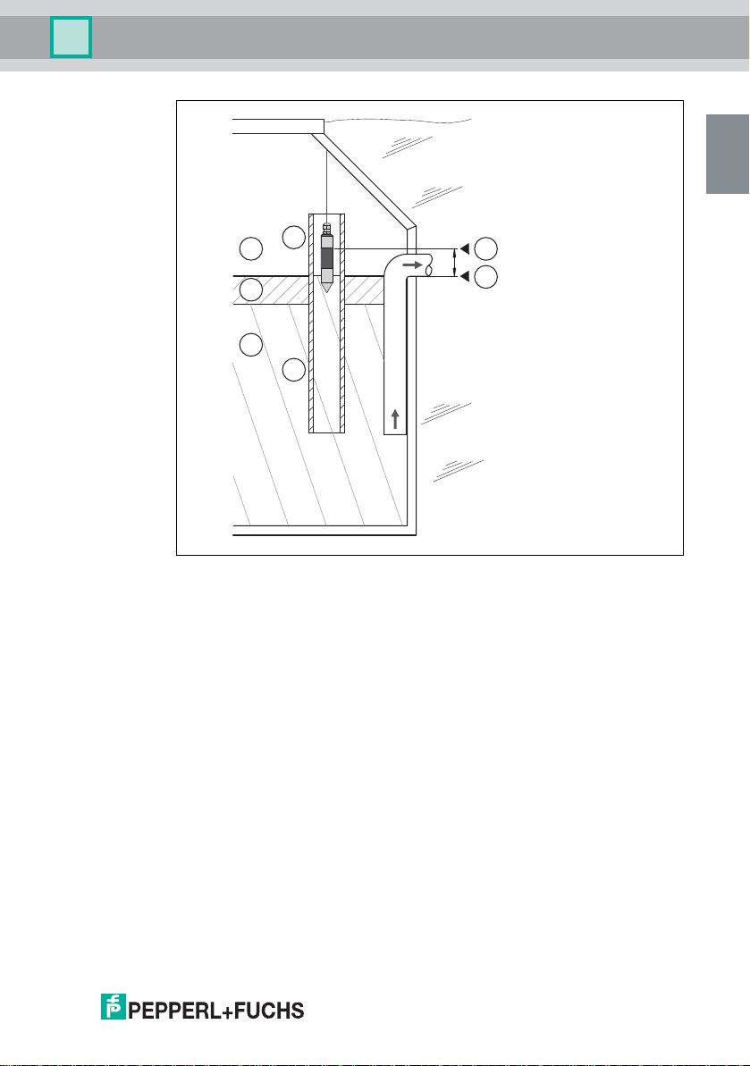
If a non-electrically conductive fat layer settles on the surface, there is a risk that a
possible overflow will not be detected by the sensor. Therefore we recommend
mounting a pitot tube for overflow sensor KVF-O. This ensures that the sensor
only comes into contact with water and the overflow is detected. The following
diagram shows the composition.
266859 2014-04
Page 17
Warning Device NVD-111
EN
B
C
A
1
D
L
S
X
Installation
Figure 3.3 Mounting the overflow sensor KVF-O with pitot tube
1 Overflow sensor KVF-O
A Air
B Fat, oil, grease (FOG)
C Water
D Open pitot tube (not supplied)
L Water zero line
266859 2014-04
S Sensor switching point
X Alarm limit (maximum liquid level)
EN - 15
Page 18

Warning Device NVD-111
EN
Installation
3.1.2 Mounting the KVF-F Fat Level Sensor
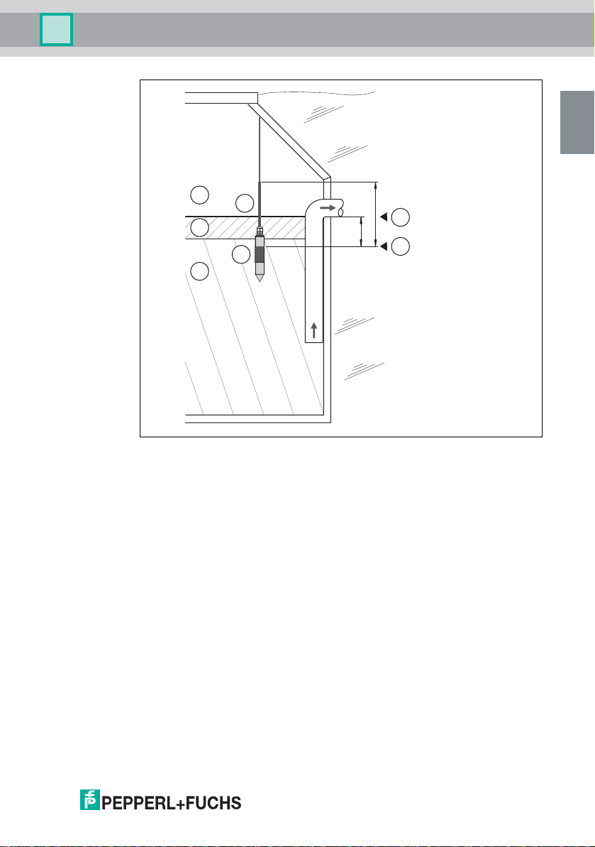
The sensor must be immersed a few centimeters when the liquid is at its normal
level (water zero line).
The exact immersion depth depends on
n the type of grease interceptor,
n its design,
n its capacity
n and the height of the maximum fat layer thickness.
The sensor must always be immersed in the liquid. The switching point of the
sensor is located between the insulated connecting piece and the top metal
section (see chapter 2.3).
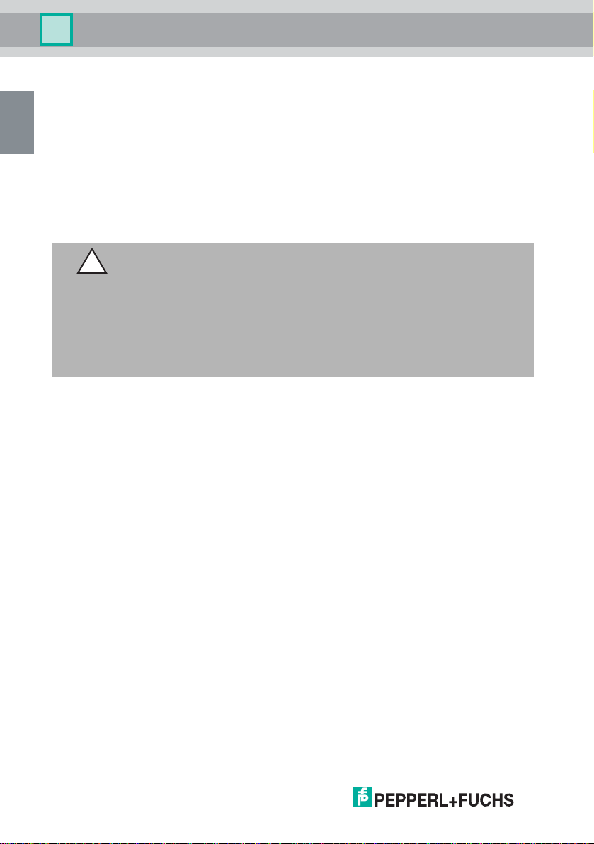
Caution!
Damage to the cable as a result of aggressive greases
The sensor cable must not be in continuous contact with grease or with water that
contains grease. The sensor is therefore fitted with shrink tubing. The shrink
tubing protects the cable from the effect of the grease to a fat layer thickness of
30 cm.
If fat layer thicknesses of more than 30 cm occur in your application, protect the
cable with additional shrink tubing.
266859 2014-04
16 - EN
Page 19
Warning Device NVD-111
EN
L
S
B
C
A
1
2
300
X
Installation
Figure 3.4 Mounting the fat level sensor
1 Fat level sensor KVF-F
2 Shrink tubing
A Air
B Fat, oil, grease (FOG)
C Water
L Water zero line
S Sensor switching point
266859 2014-04
X Alarm limit (maximum fat layer thickness)
EN - 17
Page 20
Warning Device NVD-111
EN
Installation
3.1.3 Mounting the FAU-104 Fat Level Sensor
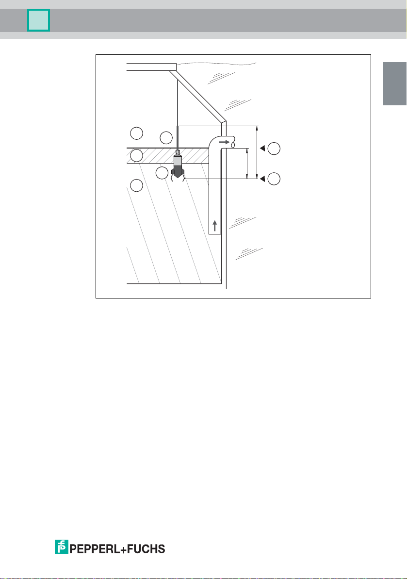
The sensor must be immersed a few centimeters when the liquid is at its normal
level (water zero line).
The exact immersion depth depends on
n the type of grease interceptor,
n its design
n and the height of the maximum fat layer thickness.
The sensor must always be immersed in the liquid. The switching point of the
sensor is located at the same level as the reflectors (see chapter 2.3).
Caution!
Damage to the cable as a result of aggressive greases
The sensor cable must not be in continuous contact with grease or with water that
contains grease. The sensor is therefore fitted with shrink tubing. The shrink
tubing protects the cable from the effect of the grease to a fat layer thickness of
30 cm.
If fat layer thicknesses of more than 30 cm occur in your application, protect the
cable with additional shrink tubing.
266859 2014-04
18 - EN
Page 21
Warning Device NVD-111
EN
L
S
B
C
A
1
2
X
300
Installation
Figure 3.5 Mounting the fat level sensor
1 Fat level sensor FAU-104
2 Shrink tubing
A Air
B Fat, oil, grease (FOG)
C Water
L Water zero line
S Sensor switching point
266859 2014-04
X Alarm limit (maximum fat layer thickness)
EN - 19
Page 22
Warning Device NVD-111
EN
Click!
Installation
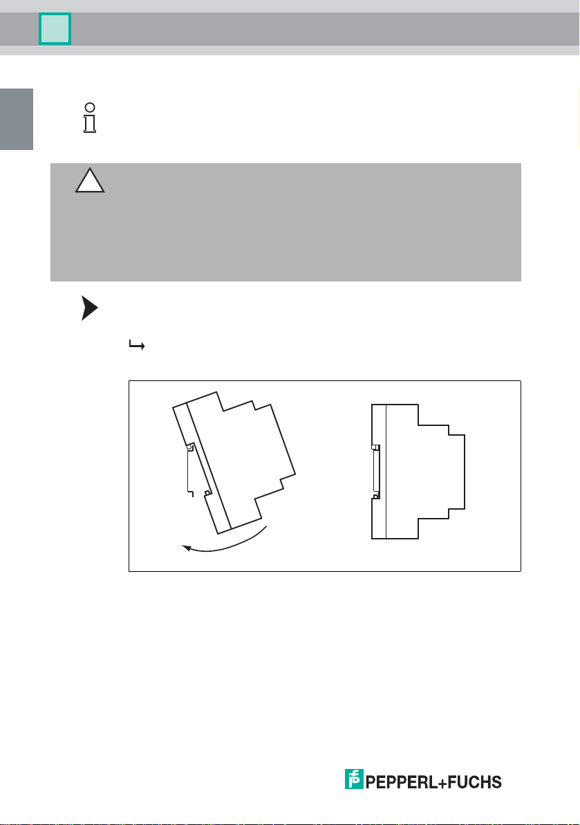
3.2 Mounting the Warning Device
Note!
If installing the device in an enclosure or switch cabinet, follow the mounting
instructions provided by the manufacturer of the enclosure or switch cabinet.
Caution!
Malfunction or damage resulting from overheating
If the external temperature exceeds 60 °C at maximum load, the device may
become damaged.
n Ensure sufficient ventilation at the installation site
n Maintain a minimum distance of 5 mm between the devices on the
DIN mounting rail.
Mounting the warning device on the DIN mounting rail.
Clip the device onto the DIN mounting rail.
The warning device engages with an audible click. The warning device is
mounted.
20 - EN
Figure 3.6
266859 2014-04
Page 23

Warning Device NVD-111
EN
Installation
3.3 Connection
Read the chapter on Safety and, in particular, the section on Installation and
Commissioning (see chapter 1.7) before installing the device. Do not remove the
identification plate.
Warn ing!
Risk of short circuit
Injuries and damage to the device are possible when working with live parts.
n Before working on the device, always disconnect the supply voltage.
n Connect the device to the supply voltage only after completion of the work.
Take care not to reverse the polarity when connecting the sensor cable. The loop
resistance of the extension cable should not exceed 20 for the sensors.
266859 2014-04
EN - 21
Page 24
Warning Device NVD-111
EN
OFF
ON
18 20 22 24
10 11 12123 567
12345678
230 V AC
3
4
1
2
bubn
Installation
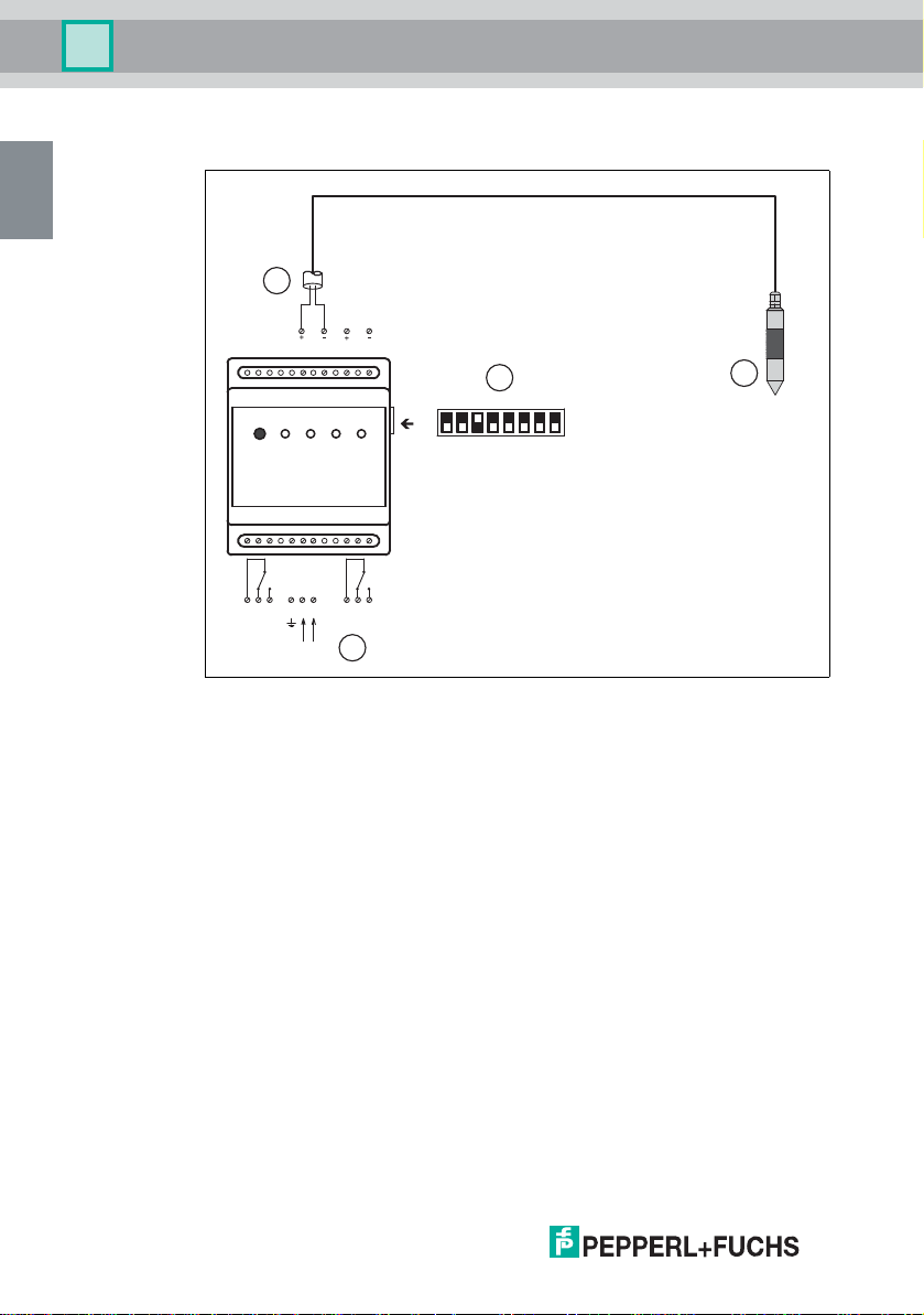
Connecting and configuring the warning device with
overflow sensor KVF-O
22 - EN
Figure 3.7
1 Overflow sensor connection
2 Overflow sensor KVF-O
3 DIP switches
4 Power supply
bu blue
bn brown
266859 2014-04
Page 25
Warning Device NVD-111
EN
OFF
ON
18 20 22 24
10 11 12123 567
12345678
230 V AC
3
4
2
1
bubn
Installation
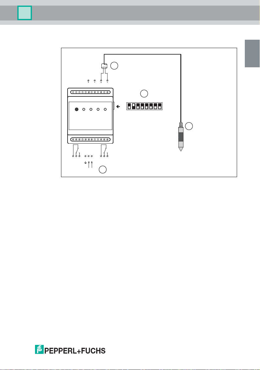
Connecting and configuring the warning device with
fat level sensor KVF-F
Figure 3.8
266859 2014-04
1 Fat level sensor connection
2 Fat level sensor KVF-F
3 DIP switches
4 Power supply
bu blue
bn brown
EN - 23
Page 26
Warning Device NVD-111
EN
OFF
ON
18 20 22 24
10 11 12123 567
12345678
230 V AC
3
4
2
1
bubn
Installation
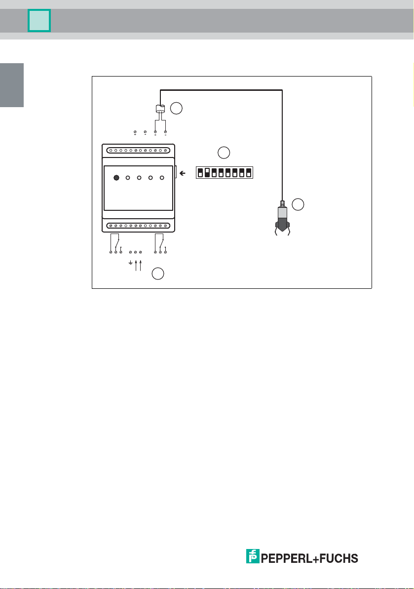
Connecting and configuring the warning device with
fat level sensor FAU-104
Figure 3.9
24 - EN
1 Fat level sensor connection
2 Fat level sensor FAU-104
3 DIP switches
4 Power supply
bu blue
bn brown
266859 2014-04
Page 27
Warning Device NVD-111
EN
OFF
ON
18 20 22 24
10 11 12123 567
12345678
230 V AC
1
4
2
5
6
3
bububn bn
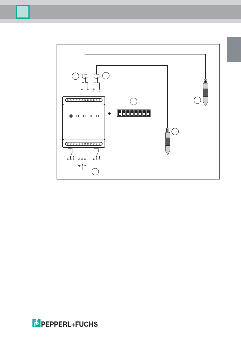
Installation
Connecting and configuring the warning device with overflow sensor
KVF-O and fat level sensor KVF-F
266859 2014-04
Figure 3.10
1 Overflow sensor connection
2 Fat level sensor connection
3 Overflow sensor KVF-O
4 Fat level sensor KVF-F
5 DIP switches
6 Power supply
bu blue
bn brown
EN - 25
Page 28
Warning Device NVD-111
EN
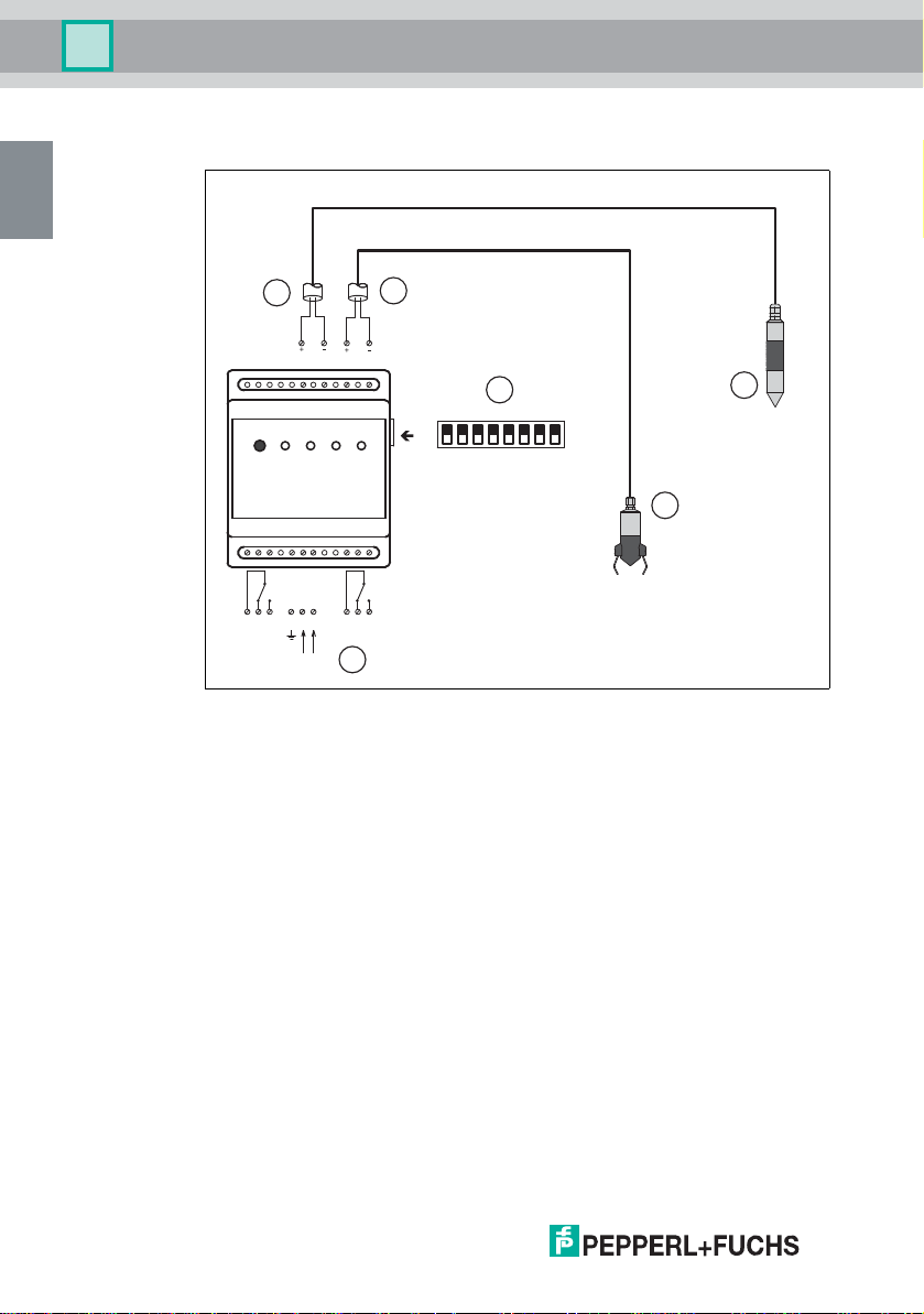
Installation
Connecting and configuring the warning device with overflow sensor
KVF-O and fat level sensor FAU-104
1
bubn
18 20 22 24
230 V AC
2
bubn
10 11 12123 567
6
Figure 3.11
1 Overflow sensor connection
2 Fat level sensor connection
3 Overflow sensor KVF-O
4 Fat level sensor FAU-104
5 DIP switches
6 Power supply
bu blue
bn brown
12345678
OFF
ON
5
4
3
266859 2014-04
26 - EN
Page 29
Warning Device NVD-111
EN
Installation
The product is a Class II device (with reinforced insulation). Connect the power
supply as follows:
n Terminal 7: phase (F/L2)
n Terminal 6: zero (N/L1)
n Terminal 5: ground (loop terminal)
Note!
Additional relays can be connected via terminals 1 to 3 and 10 to 12. They can be
used, for example, for an external alarm or the connection to a central monitoring
system.
For extending the sensor cable, use cable connector LAL-SK2.
Note!
Avoid routing the sensor cable parallel to other cables, as these cables may
transmit interfering signals. These interfering signals may affect the sensor signal
and impair the alarm function. Use unshielded 2-strand cables for each sensor.
To ensure the warning device functions correctly, do not exceed the following
maximum sensor cable lengths:
n With a cable cross section of 0.75 mm
190 m.
n With a cable cross section of 1 mm
2
, the maximum cable length is
2
, the maximum cable length is 250 m.
266859 2014-04
EN - 27
Page 30

Warning Device NVD-111
EN
Commissioning
4 Commissioning
4.1 Configuring the Warning Device using DIP Switches
Often, suspended particles (e. g. leftovers) can be found in the grease interceptor
and lumps of fat often form. These suspended particles and lumps of fat can
cause a false alarm for the fat level sensor. Therefore, it is possible to set two
possible monitoring states for the fat level sensor on the warning device via the
setting of DIP switch 1 (reaction time of the fat level sensor).
266859 2014-04
28 - EN
Page 31

Warning Device NVD-111
EN
Commissioning
Switch setting ON – operating mode
n The reaction time for detection of a fat layer is 24 hours (warning device in
normal mode, green "SYSTEM OK" LED lights up). The device becomes
active only after the fat level sensor has remained in a fat layer undisturbed
for a period of 24 hours.
• The device uses the "FAT LAYER ALARM" LED to display the
alarm status.
• The device triggers an audible alarm where necessary.
• The device activates the relay.
n The reaction time for detection of water is 1 hour (warning device in alarm
mode, red "FAT LAYER ALARM" LED lights up). The device becomes
active only after the fat level sensor has remained in water undisturbed for
a period of 1 hour.
• The "FAT LAYER ALARM" LED goes out.
• The "SYSTEM OK" LED flashes.
Note!
Note that the "SYSTEM OK" LED light ups under the following conditions:
n After switching on the warning device
n After switching the DIP switch from OFF to ON
n After pressing and holding the "ALARM RESET" button
(approximately 3 to 4 seconds)
The device becomes active only after the fat level sensor has remained in a fat
layer undisturbed for a period of 24 hours.
n The device uses the "FAT LAYER ALARM" LED to display the alarm
status.
n The device triggers an audible alarm where necessary.
n The device activates the relay.
266859 2014-04
EN - 29
Page 32
Warning Device NVD-111
EN
Commissioning
Switch setting OFF – service/test mode
After switching on the warning device or after switching the DIP switch from
ON to OFF, an alarm is detected immediately and the warning device displayed.
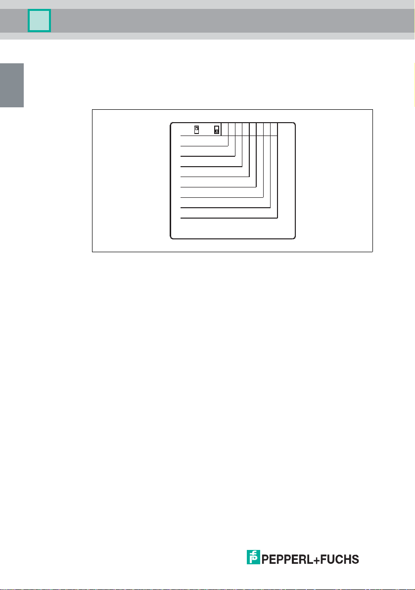
The DIP switches are located on the right of the device (see chapter 2.3).
Figure 4.1 Overview of the warning device DIP switches
1 23458
ON
OFF
Reaction time
KVF-O
FAU-104 / KVF-F
Acoustic alarm
Relay setting
Relay setting
Repeat alarm in 24 hours
Reset key
Refer servicing to qualified personel.
76
266859 2014-04
30 - EN
Page 33
Warning Device NVD-111
EN
Commissioning
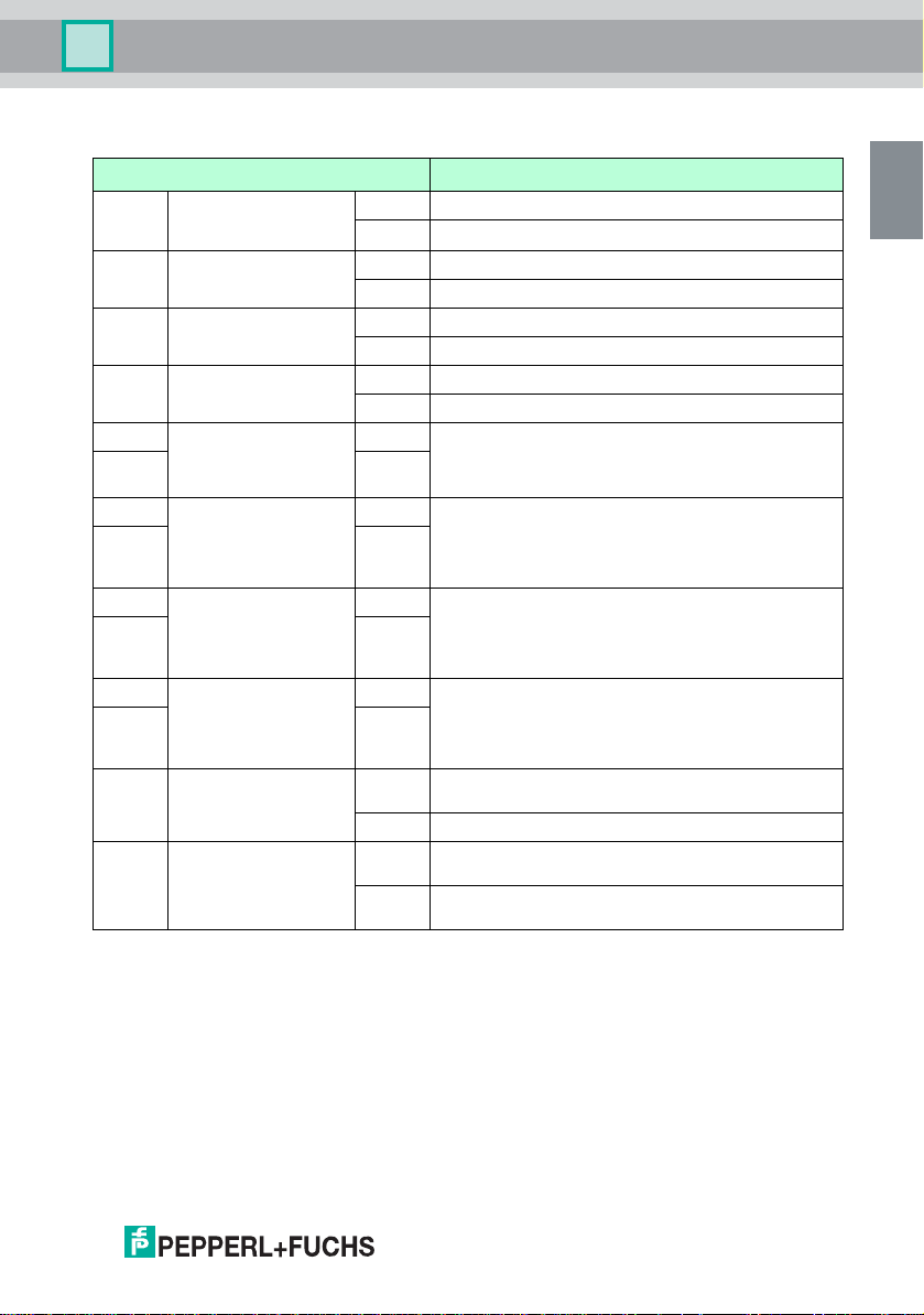
The following table contains a list of possible configuration settings.
Switches Description
DIP 1 Reaction time (reaction
DIP 2 Overflow sensor KVF-O ON connected
DIP 3 Fat level sensor KVF-F
DIP 4 Acoustic alarm ON Acoustic alarm on.
DIP 5 Relay setting ON Relays 1 and 2 switch irrespective of the alarm states and
DIP 6 ON
DIP 5 Relay setting ON Relays 1 and 2 switch, irrespective of the alarm states.
DIP 6 OFF
DIP 5 Relay setting OFF In the case of active alarm status, relay 1 switches to
DIP 6 ON
DIP 5 Relay setting OFF Relays 1 and 2 switch, irrespective of the alarm states. If
DIP 6 OFF
DIP 7 Repeat alarm in 24
DIP 8 Reset key (ALARM
time of the fat level
sensor)
or FAU-104
hours
RESET activation)
ON Operating mode – delay of the sensor reaction
OFF Service/test mode – instant sensor reaction
OFF not connected
ON connected
OFF not connected
OFF Acoustic alarm off.
with which sensor. If the alarm status disappears, relays 1
and 2 switch again (if “ALARM RESET” is actuated, the
relays switch again).
After 3 minutes, relay 2 switches again (even if an alarm
status is present). If the alarm status disappears, relay 1
and/or relay 2 switches again (if “ALARM RESET” is
actuated, the relays switch again).
overflow sensor KVF-O and relay 2 switches to fat level
sensor KVF-F/FAU-104. If the alarm status disappears,
relay 1 and/or relay 2 switch again (if “ALARM RESET” is
actuated, the relays switch again).
an alarm event is no longer present, relay 1 automatically
switches back and relay 2 remains unchanged until the
alarm is cleared by actuating “ALARM RESET”. It shows
that an alarm occurred.
ON Repeat alarm on. This also applies to the function of
OFF Repeat alarm off.
ON "ALARM RESET" button is activated. The acoustic alarm
OFF "ALARM RESET" button is deactivated. The acoustic
relays 1 and 2.
and the alarm relay can be reset.
alarm and the alarm relay cannot be reset.
266859 2014-04
EN - 31
Page 34
Warning Device NVD-111
EN
Operation
5Operation
5.1 Alarm Signals
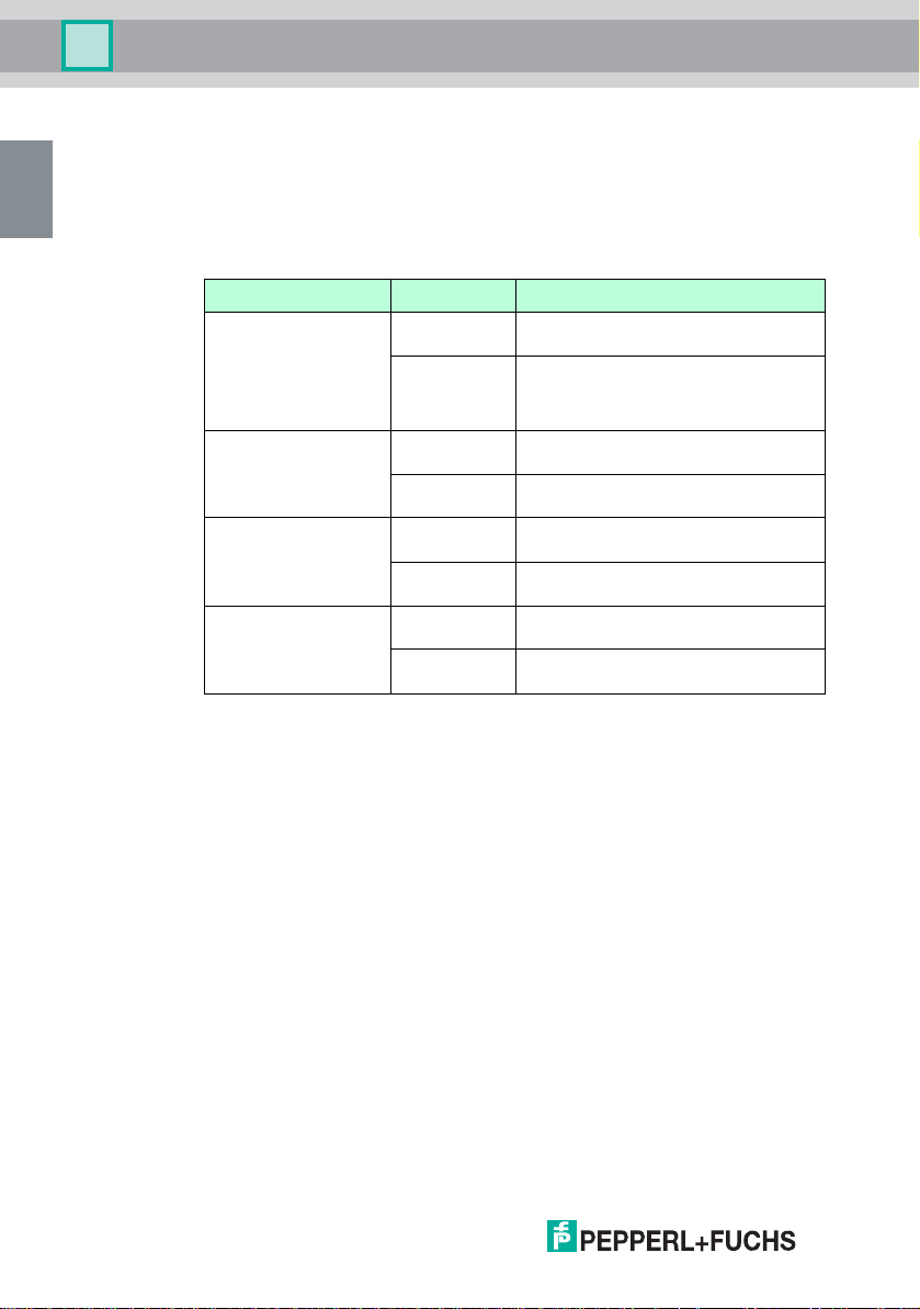
The warning device indicates an alarm status or sensor fault both visually and
acoustically. The respective “OVERFLOW ALARM” or “FAT LAYER ALARM”
LEDs are illuminated until the system returns to a normal status.
LED Status Meaning
Yellow LED “SUPPLY” lights up The device is connected to the power
flashes briefly Prerequisite DIP switch 1 = ON
Green LED
“SYSTEM OK”
Red LED
“OVERFLOW ALARM”
Red LED
“FAT LAYER ALARM”
lights up No errors or alarms active – normal
flashes No alarm or error active, there was an
lights up Alarm active, overflow sensor is covered
flashes Internal sensor error, lead breakage or
lights up Alarm active, fat level sensor is covered
flashes Internal sensor error, lead breakage or
supply. The device is in operation.
In this mode, a brief flash of the “SUPPLY”
LED indicates that a change in status has
been detected by the sensor.
operation
alarm or error in the past.
with liquid.
short-circuit
with fat.
short-circuit
266859 2014-04
32 - EN
Page 35

Warning Device NVD-111
EN
Operation
5.2 Resetting the Alarm Signal
There are two options available to reset the alarm.
Briefly press the “ALARM RESET” button
The acoustic alarm is switched off. The potential-free relay is reset.
Press and hold the “ALARM RESET” button (for approx. 3 to 4 seconds)
Combined test and reset function
The test function is started by pressing and holding the button.
n The LEDs light up in turn briefly.
n The acoustic alarm is briefly activated.
n Both relays are activated in turn.
The reset function is started (prerequisite DIP switch 1 (“Reaction time”) is ON)
n The hour counters (1 hour or 24 hours) are set to 0.
n The “System OK” LED lights up. If there is a current fat layer alarm, this
alarm status is only displayed after 24 hours via the “FAT LAYER ALARM”
LED and, if applicable, an acoustic alarm triggered and relay activated.
Note!
In the event of lead breakage or short-circuit, irrespective of the setting of the
DIP switch 1 (“Reaction time”) immediately an alarm status is displayed via the
“FAT LAYER ALARM” LED and, if applicable, an acoustic alarm triggered and
relay activated.
266859 2014-04
EN - 33
Page 36
Warning Device NVD-111
EN
Operation
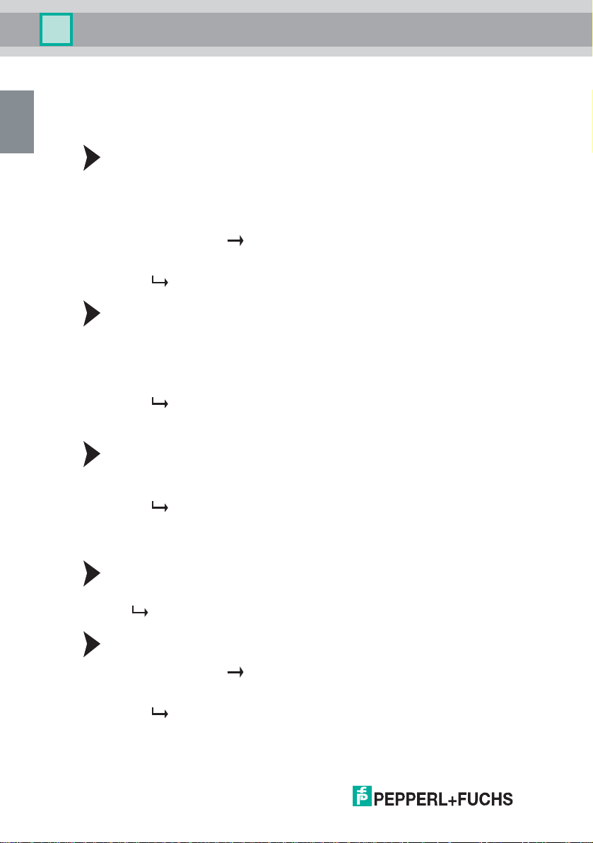
5.3 Function Testing
Fat level sensors
Checking the normal status
Checking the normal status for fat level sensor KVF-F
1. Switch DIP switch 1 to position OFF.
2. Remove the sensor from the grease interceptor.
3. Wash and dry the sensor.
4. Hold the sensor in your hand (no gloves). Only touch the upper and lower
metal section ( see Figure 2.3 on page 9) or
5. Immerse the sensor in water.
The green "SYSTEM OK" LED on the warning device flashes or lights up.
Checking the normal status for fat level sensor FAU-104
1. Switch DIP switch 1 to position OFF.
2. Remove the sensor from the grease interceptor.
3. Wash and dry the sensor.
4. Immerse the sensor in water.
The green “SYSTEM OK” LED flashes or lights on the warning device.
Checking the alarm status
Checking the alarm situation for fat level sensors
1. Switch DIP switch 1 to position OFF.
2. Suspend the KVF-F or FAU-104 fat level sensor freely in air.
The red “FAT LAYER ALARM” LED lights and, if applicable, an acoustic
signal sounds.
Overflow sensor
Checking the normal status
Suspend the sensor freely in air.
The green “SYSTEM OK” LED lights on the warning device.
Checking the alarm situation
1. Hold the sensor in your hand (no gloves). Only touch the upper and lower
metal section ( see Figure 2.3 on page 9) or
2. Immerse the sensor in water.
The red “OVERFLOW ALARM” LED lights and, if applicable, an acoustic
signal sounds.
266859 2014-04
34 - EN
Page 37
Warning Device NVD-111
EN
Troubleshooting
6 Troubleshooting
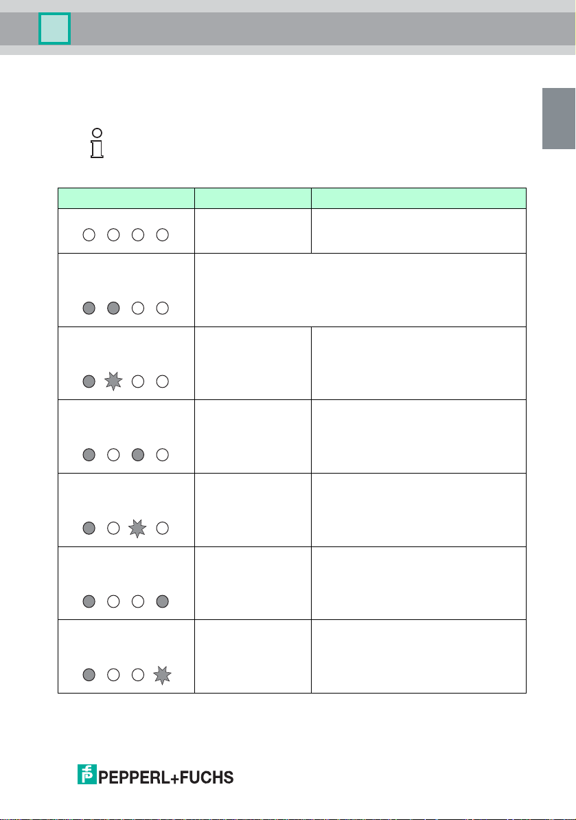
6.1 Troubleshooting and Alarm States
Note!
If switched on (“Acoustic alarm” DIP switch) an acoustic signal sounds in the
event of an alarm and sensor malfunction.
LED indication Cause Action
All LEDs are off. The warning device is
not functioning.
Check that the supply voltage is connected.
n “SUPPLY” LED lights up.
n “SYSTEM OK” LED lights
up.
n “SUPPLY” LED lights up.
n “SYSTEM OK” LED
flashing.
n “SUPPLY” LED lights up.
n “OVERFLOW ALARM”
LED lights up.
n “SUPPLY” LED lights up.
n “OVERFLOW ALARM”
LED flashing.
n “SUPPLY” LED lights up.
n “FAT LAYER ALARM”
LED lights up.
n “SUPPLY” LED lights up.
n “FAT LAYER ALARM”
LED flashing.
No alarm at present. The warning system is operating normally.
No alarm at present. An
alarm occurred in the
past.
Excessive liquid level It is essential to check the separator status. If
Sensor fault or lead
breakage
Maximum fat layer
thickness is reached.
Sensor fault or lead
breakage
1. Check the status of the separator.
2. Press the “ALARM RESET” button.
necessary, takes measures to stop the alarm
situation. The alarm situation can arise from a
faulty or blocked drain.
Check sensor and sensor installation and
replace the overflow sensor, if necessary.
It is essential to check the separator status.
Empty (disposal) the grease interceptor, if
necessary.
Check sensor and sensor installation and
replace the fat level sensor, if necessary.
266859 2014-04
EN - 35
Page 38

Warning Device NVD-111
EN
Troubleshooting
6.2 Sensor Maintenance
Caution!
Malfunction or false alarm caused by a contaminated sensor
If the sensor is very dirty, this may trigger a false alarm or mean that no alarm is
triggered under certain circumstances.
n Clean and dry the sensor when emptying/disposing of the oil/petrol
separator or container.
n Do not clean the sensor with corrosive liquids.
Cleaning the Sensor
The sensor is maintenance free. To ensure the entire alarm system functions
correctly, clean the sensor at the following intervals:
1. Clean the sensor at least once a year.
2. Pay particular attention to cleaning the sensor tips of all oil, grease, and other
dirt residues using a grease-dissolving cleaning agent.
3. If the sensor is used in difficult conditions, clean the sensor more often.
266859 2014-04
36 - EN
Page 39
Warning Device NVD-111
EN
Technical Specifications
7 Technical Specifications
7.1 Warning Device NVD-111
Power su pply
Rated voltage 230 V AC ± 10%, 50 Hz … 60 Hz
Power consumption 4.5 VA … 6 VA
Max. fusing 10 A
Overvoltage category III
Connection terminals 5, 6, 7
Input
Connection overflow
sensor KVF-O
Connection fat level sensor
KVF-F or FAU-104
Output
Connection relay 1 terminals 1, 2, 3
Connection relay 2 terminals 10, 11, 12
Output potential-free changeover contact
Contact load 250 V AC/4 A/100 VA
Galvanic isolation
Output/supply reinforced insulation acc. to EN 50178, rated insulation
Output/output reinforced insulation acc. to EN 50178, rated insulation
Ambient conditions
Ambient temperature -25 °C … 60 °C (248 … 333 K)
Mechanical specifications
Mass approx. 325 g
Protection degree IP20
Mounting DIN mounting rail acc. to EN 60715
Dimensions 70 mm x 86 mm x 58 mm
terminals 18, 20
terminals 22, 24
voltage 300 V
voltage 300 V
eff
eff
266859 2014-04
EN - 37
Page 40
Warning Device NVD-111
EN
Technical Specifications
7.2 Overflow Sensor KVF-O
Power supply
Rated voltage 13 V DC
Ambient conditions
Ambient temperature -20 °C … 60 °C (253 K …333 K)
Mechanical specifications
Protection degree IP68
Connection cable
Material stainless steel
Cable 5m
Mass approx. 520 g
Dimensions 31.6 mm x 138 mm
7.3 Fat Level Sensor KVF-F
Power supply
Rated voltage 13 V DC
Ambient conditions
Ambient temperature -20 °C … 60 °C (253 K … 333 K)
Mechanical specifications
Protection degree IP68
Connection cable
Material stainless steel
Cable 5m
Mass approx. 520 g
Dimensions 31.6 mm x 138 mm
7.4 Fat Level Sensor FAU-104
Power supply
Rated voltage 13 V DC
Ambient conditions
Ambient temperature -20 °C … 60 °C (253 K …333 K)
Mechanical specifications
Protection degree IP68
Connection cable
Material stainless steel
Cable 5m
Mass approx. 410 g
Dimensions 38/66 mm x 152 mm
266859 2014-04
38 - EN
Page 41

Subject to modifications
Copyright PEPPERL+FUCHS • Printed in Germany
www.pepperl-fuchs.com
PROCESS AUTOMATION –
PROTECTING YOUR PROCESS
Worldwide Headquarters
Pepperl+Fuchs GmbH
68307 Mannheim · Germany
Tel. +49 621 776-0
E-mail: [email protected]
For the Pepperl+Fuchs representative
closest
to you check www.pepperl-fuchs.com/contact
266859 DOCT-1951A
04/2014
 Loading...