

Page 1
PROCESS AUTOMATION
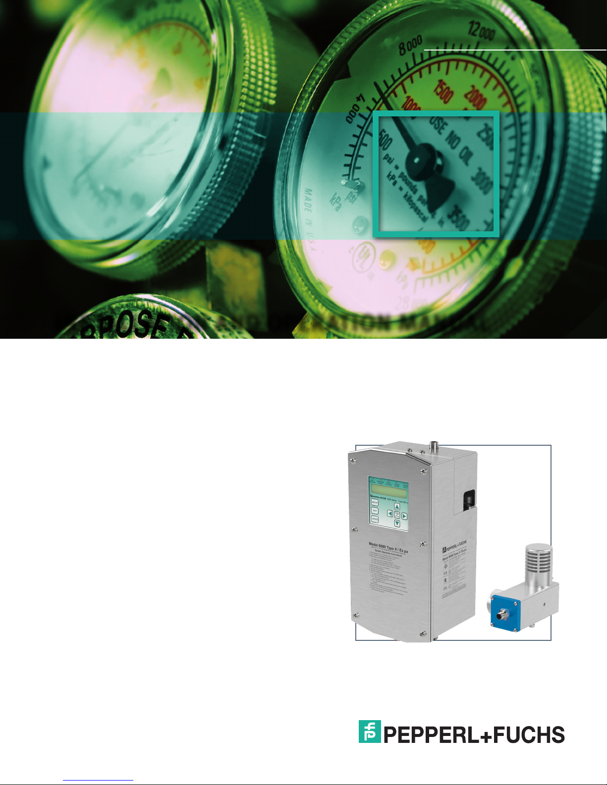
INSTALLATION AND OPERATION MANUAL
6000 SERIES
PURGE/PRESSURIZATION SYSTEM
Page 2

6000 Series Purge/Pressurization System
I/O Manual
With regard to the supply of products, the current issue of the
following document is applicable:
The General Terms of Delivery for Products and Services of
the Electrical Industry, published by the Central Association
of the Electrical Industry (Zentralverband Elektrotechnik und
Elektroindustrie (ZVEI) e.V.) in its most recent version as
well as the supplementary clause: "Expanded reservation of
proprietorship".
b
Page 3

6000 Series Purge/Pressurization System
I/O Manual
Contents
Safety note and symbols used ................................................................................................. 1
Symbols used ....................................................................................................................................1
General instructions regarding ATEX ...................................................................................... 2
Certication information ........................................................................................................... 3
Certication markings .......................................................................................................................3
Warning labels ...................................................................................................................................4
Conditions of Safe use ......................................................................................................................4
Purpose ......................................................................................................................................5
Description ................................................................................................................................. 5
6000 control unit .......................................................................................................................6
Electrical & pneumatic diagrams ............................................................................................. 8
6000 control unit power connections ..............................................................................................8
Electrical installation - power and I.S. wiring ................................................................................ 10
Pneumatic requirements ................................................................................................................. 12
Mounting instructions ............................................................................................................. 13
Manifold assembly, LH & RH mount ..............................................................................................13
EPV-6000 vent .................................................................................................................................. 14
6000 Control unit with housing "WH" ...........................................................................................15
Tightening the cover plate ..............................................................................................................16
6000 series component kit ..................................................................................................... 17
Identication of components .........................................................................................................17
Electrical diagrams ......................................................................................................................... 18
Electrical installation - power and I.S. wiring ................................................................................ 20
Component kit installation .............................................................................................................21
Mounting templates - user interface, EPCU, solenoid .................................................................22
Sequence of events ................................................................................................................. 23
Turning on power to the enclosure ................................................................................................23
Turning off power to the enclosure ...............................................................................................24
Operation of the 6000 series and component kit ................................................................. 25
Operation ..........................................................................................................................................25
Set-up procedures of 6000 series system ....................................................................................29
Operation of the 6000 series system .............................................................................................29
Start-up label located on 6000 series control unit .......................................................................30
The user interface ....................................................................................................................31
Programming menu ................................................................................................................. 32
Purge settings ..................................................................................................................................33
Units ..................................................................................................................................................33
Inputs ................................................................................................................................................34
Outputs .............................................................................................................................................38
Password ..........................................................................................................................................39
Language ..........................................................................................................................................39
Bypass control .................................................................................................................................39
Restore defaults ..............................................................................................................................39
Stats ..................................................................................................................................................40
Statistics ...........................................................................................................................................41
Alarm.................................................................................................................................................43
c
Page 4

6000 Series Purge/Pressurization System
Fault ..................................................................................................................................................43
Clear statistics ................................................................................................................................44
Clear fault ........................................................................................................................................44
Operation screen .............................................................................................................................44
I/O Manual
System dimensions ................................................................................................................. 45
6000 series control unit ..................................................................................................................45
EPV-6000 vent .................................................................................................................................. 46
6000 series component kit .............................................................................................................47
Temperature hub .............................................................................................................................48
Temperature sensor ........................................................................................................................49
6000 Manifold ...................................................................................................................................50
General specications ............................................................................................................51
Model number designators .....................................................................................................54
Accessories .............................................................................................................................55
Maintenance and repair ..........................................................................................................56
Alarm and fault conditions .....................................................................................................56
Dismantling and decommissioning .......................................................................................57
Establishing connection sizes, lengths & bends ................................................................. 58
Programming worksheet .........................................................................................................59
Notes .........................................................................................................................................66
d
Page 5

6000 Series Purge/Pressurization System
Warning
Note
Safety note and symbols used
It is strongly urged that you follow all instructions and
recommendations in this manual, in addition to all
applicable codes, standards, and local requirements.
Failure to do so voids all warranties, both implicit and
explicit, and relieves the manufacturer of all liability.
Symbols used
This symbol calls your attention to
instructions or requirements that must be
followed. Failure to observe the instructions
and information that this symbol calls
Attention
attention to may result in the failure of the
device and any devices or systems
connected to it.
This symbol draws your attention to
important information.
Note
I/O Manual
This symbol warns the user of potential
danger. Failure to observe this warning may
lead to personal injury or death and/or
property damage.
This symbol accompanies a list of tools you
will need to install the unit.
Grounding points internal and external
will be identied with a ground symbol:
This symbol is used for AC power:
This symbol is used for DC power:
Pepperl+Fuchs GmbH
Lilienthalstraße 200
68307 Mannheim
Germany
1
Page 6
6000 Series Purge/Pressurization System
Note
Warning
Warning
I/O Manual
General instructions regarding ATEX
1. The guidelines
The guideline 2014/34/EU determines the essential
health and safety requirements relating to the design
and construction of equipment and protective systems
intended for use in potentially explosive atmospheres,
given in Annex II of the directive.
The guideline 1999/92/EG is addressed to the operator/
user of facilities in explosive areas and governs the
safety regulations of persons during installation, handling,
and maintenance.
Furthermore, local laws and rules for electrical
installations and accident prevention have to be
observed.
2. General information for this manual
Preconditions for handling and operating the series
6000 controller safely are basic knowledge of safety
regulations and additional training and experience in
explosion protection.
4. General information about pressurized enclosures
The pressurized enclosure is one of the most
multifunctional applicable types of protection. It is based
on a rst ush operation which removes potential,
ignitable gas mixtures of the local environment from
the enclosure. After the ush, the overpressure will
be maintained by adding as much pressurized air as
necessary to compensate for the leaks of the enclosure
or components. This constant overpressure status
protects against the diffusion of potentially explosive
atmospheres.
During the ush, the internal pressure will be up to
10-12mbar. In the operation phase, it is reduced to
2-3 mbar. Hot spots at single components inside the
enclosure are monitored by temperature sensors
(optional) and if required turned off. This assures that no
unacceptable surface temperature will occur.
For applications with hazardous dust, the purge process
is omitted because purging would raise explosive dust.
Instead of pre-purging, the interior of the housing is
inspected for dust and cleaned manually if dust is
present.
This user manual contains important information and
instructions to handle the series 6000 controller in
explosive areas safely and to operate it according to
guideline 2014/34/EU.
This user manual, in particular the safety instructions,
has to be observed by everybody who works with the
components.
3. Responsibilities of users and installers
This equipment shall only be used within its
intended purpose. Refer to the manual for proper
usage.
The user and/or the installer is obligated to let only
competent, trained persons work at the 6000 Control Unit
who
• are familiar with the regulations about safety and
accident prevention and briefed in handling of the
component.
• are trained to work on explosion protection
equipment.
• know the appropriate instructions and rules for
the installation, handling, and maintenance of
explosion protected equipment.
For this reason, the pressurized enclosure is especially
suited for the use of non-Ex certied equipment in Exareas.
The enclosure has to be prepared specially for the use of
Ex p:
• all walls have to be additionally armed
• the doors have to be specially constructed
• tested for mechanical stability
• tested for overpressure resistance
When using an inert gas like nitrogen, an
asphyxiation hazard can exist.
EN 60079-2 and IEC 60079-2 do not cover both gas
and dust hazard atmospheres. The 6000 system
provides a solution for both at the same time but
would have to be evaluated by the certication
bodies for approval.
2
Page 7

6000 Series Purge/Pressurization System
Certication information
Marking for the 6000 control unit,
6000-__-S2-__-CK-__
Marking for the 6000 Control
unit, 6000-__-S2-UN-WH-__ and
6000-__-S2-__-XD-__
I/O Manual
Marking for the 6000 user interface controller, 6000-UIC-01
Marking for the 6000-ISB-___ termination board,
DIN mounted
Marking for the 6000 vent, EPV-6000-__-__
Marking for the 6000-TSEN-01
Marking for the 6000-TEMP-01
3
Page 8

6000 Series Purge/Pressurization System
Warning
Warning
Warning
Warning
I/O Manual
Warning Labels
WARNING - Conduit seal must be installed within 18
inches of the explosion-proof enclosure. To prevent
ignition of ammable or combustible atmospheres,
disconnect power before servicing.
WARNING - FOR ENCLOSURES IN HAZARDOUS
DUST ENVIRONMENTS
This enclosure shall not be opened unless the area
is known to be free of ammable materials or unless
all devices have been de-energized. Power must not
be restored after the enclosure has been opened until
combustible dusts have been removed and the enclosure
repressurized.
WARNING - FOR ENCLOSURES IN HAZARDOUS
GAS ENVIRONMENTS
This enclosure shall not be opened unless the area is
known to be free of ammable materials or unless all
devices have been de-energized. Power must not be
restored after the enclosure has been opened until the
enclosure is completely purged of all hazardous gas and
the enclosure repressurized.
WARNING - FOR ENCLOSURES IN HAZARDOUS
DUST AND GAS ENVIRONMENTS
This enclosure shall not be opened unless the area
is known to be free of ammable materials or unless
all devices have been de-energized. Power must not
be restored after the enclosure has been opened until
combustible dusts have been removed and completely
purged of all hazardous gas and the enclosure
repressurized.
Conditions of Safe Use
1. Conduit seals shall be certied in type of explosion
protection ameproof “db”, or explosion-proof Class
I/II Div 1 as required for the installation location
and suitable for the conditions of use. They shall be
correctly installed to the explosion-proof/ameproof
enclosure or conduit extensions as required. All NPT
threads are to be minimum 5 thread engagement,
wrench tight.
2. Seals shall be installed within 18 in. (450 mm) of the
explosion-proof/ameproof “db” enclosure.
8. The non-metallic membrane touchpad and display is
a potential electrostatic discharge hazard. Use only
water damp cloth and allow to air dry for cleaning
device. Do not use or install in high charge areas.
See IEC 60079-32-1 for further information.
9. In hazardous dust environment, regularly remove dust
from the control unit enclosure to prevent excessive
temperature rise, including the solenoid valve.
10. Only pressure relief vent model EPV-6000-xx-xx
covered under the following certicates can be
used with devices covered by this certicate: For
ATEX applications: Certicate No. DEMKO 15
ATEX 1622X, DEMKO 07 ATEX 0705753X, or SIRA
09ATEX9337X. For IECEx applications: Certicate
No. IECEx UL 15.0147X, IECEx UL 08.0003X or
IECEx CSA 09.0007X. For cULus and cCSAus
applications: UL certication as part of le E184741
or CSA certication as part of 2205652 (LR90178).
11. For all applications, the 6000-TEMP-XX I.S.
temperature hub must be mounted in an enclosure
that is a minimum IP54. In hazardous dust
environment, the 6000-TEMP-xx temperature hub
has to be mounted in an enclosure that is certied
for the area classication. The pressurized enclosure
does not account for this type of enclosure because
power to this device is required before safe operation
within the pressurized enclosure. Maintain separation
of I.S. to non-I.S. wiring as required by local codes.
12. Caution must be used when handling or cleaning
products so there is no static charge buildup. Do not
wipe off the 6000-TSEN-xx sensor with dry cloth
or use in the presence of high charge generating
processes such as ionizers or electrostatic
equipment. See IEC 60079-32-1 for further
information.
13. The 6000 systems may also be provided with
previously certied items (operators, gable glands,
terminal box, etc.) as specied in the test reports.
14. Enclosure 6000-DPE-xx is only for I.S. termination
board 6000-ISB-xx and/or 6000-TEMP-xx.
3. When the purge control unit is mounted to an
enclosure, the complete unit shall be evaluated to
the current revision of IEC/EN 60079-2 or NFPA 496
as applicable. See certicates and/or Declaration of
Conformity for reference to relevant editions of these
standards.
4. The purge control unit has an operating temperature
class of 135 °C (T4 temperature class). This
temperature shall be considered when mounted to an
enclosure.
5. The device must be installed in accordance with the
manufacturer’s installation drawing number 116-B027.
6. Intrinsically safe cables extending from the explosionproof/ameproof "db" enclosure must be provided
with at least 0.25 mm insulation thickness per
conductive core to maintain segregation between
intrinsically safe circuits.
7. The cable entries may be used only in places
where they are protected against the inuence of
mechanical danger.
4
I.S. Termination Board, DIN Mounted:
6000-ISB-xx
1. In hazardous dust environments, the I.S. termination
board, DIN mounted: 6000-ISB-xx must be mounted
in an enclosure that is certied for the area
classication. The pressurized enclosure does not
account for this type of enclosure because power to
this device is required before safe operation within
the pressurized enclosure.
2. Only connect to the 6000 EPCU I.S. termination
connection.
3. All wiring to and from this board is for intrinsically
safe connections and must be properly routed and
managed per international, NEC, local codes, and
applicable standards.
4. See the latest revision of installation drawing 116B027 for other important installation information.
5. The 6000-CBLA-… is not certied to be used in a
Zone 21 location. Use approved cable glands for this
area classication.
Page 9

6000 Series Purge/Pressurization System
Note
I/O Manual
Note:
• Peripheral devices such as optional SRM module and
I.S. solenoid were not evaluated by UL as part of the
intrinsically safe certication.
• When using third-party certication, ensure that you
match the entity parameters for intrinsically safe
devices as shown in control drawing 116-B027.
• SRM module is a simple apparatus and does not
require third-party certication.
EPV-6000 Vent
1. The EPV vent has an operating temperature class of
135 °C (T4 temperature class). This temperature shall
be considered when mounted to an enclosure.
2. When the purge control unit is mounted to an enclosure,
the complete unit shall be evaluated to IEC/EN 600792: 2014 (Ed. 6)
3. Cables used to connect to an EPV- vent must be
provided with at least 0.25 mm insulation thickness
per conductive core to maintain segregation between
intrinsically safe circuits.
4. In hazardous dust environments, regularly remove dust
from the EPV vent to prevent excessive temperature
rise. See certicate for full information.
5. In hazardous dust environments, the connector end of
the vent shall be protected from direct exposure of a UV
light source. See certicate for full information.
The 6000 series system features these main parts:
• Electronic processor (EPCU) housed in an
explosion-proof enclosure
• I.S. electrical/pneumatic manifold assembly
• I.S. user interface for programming and monitoring
the system
• 316L stainless steel (UNS S31603) type4X IP66
enclosure for EPCU and connections
• Pressure relief vent with ow and pressure
monitoring at the exhaust.
The user interface allows programming of up to 4 switch
inputs, temperature modules, enclosure power contacts,
2 auxiliary outputs, and various operational functions.
Through the user interface menus, conguration of the
standard information for setup and operation of a system
(purge time, ow rates, pressures, enclosure size, etc.)
are easily programmed. Additional features allow inputs
for system bypass, enclosure power on/off, temperature
overload and activation of rapid exchange ow for cooling
or auxiliary relay for separate cooling source, delay
power shutdown, and more. The two auxiliary contact
outputs can be congured to activate on most of the
input switches or any of the congured alarm states for
pressure, ows, and temperature.
6. Only EPV-6000-xx-xx vents can be connected to any
certied model 6000 control system.
Purpose
The purpose of the Pepperl+Fuchs 6000 series Type X
& Ex px, Zone 1 enclosure protection system is to allow
the use of general purpose or non-rated electrical or
electronic devices located in general purpose enclosures
instead of explosion-proof/ameproof, Type 7 or 9 / Ex
d enclosures or other means of protection for the rated
area. Other purposes include heat, moisture, and dust
contamination prevention.
Description
The 6000 series Type X & Ex px purge and
pressurization system protects general purpose
equipment mounted in a standard enclosure. This allows
the enclosure to be located and the equipment operated
in a hazardous area. The hazardous area classication
can be Class I, Class II, Division 1 / Zone 1, Zone 21.
The 6000 series operates by controlling and monitoring
compressed instrument air or inert gas through the
protected enclosure(s) so as to remove and prevent the
accumulation of ammable gas, vapors, or dust.
The power for the solenoid valve on the manifold unit,
inputs, the user interface controller (UIC), and EPV-6000
vent are provided by the EPCU through the internal
galvanically isolated intrinsic safety barrier. No additional
I.S. barrier is required.
The adjustable mounting bracket and the universally
mountable vent make the 6000 system easy to install
horizontally or vertically onto the enclosure. A component
kit is available for custom installations that t specic
customer needs.
The 6000 control unit can monitor multiple enclosures
and control and accept inputs from two (2) EPV-6000
vents.
The 6000 series provides a complete system for purging
and pressurizing enclosures for hazardous location
operation.
One (1) operations copy of this manual must be
studied and retained by the system operator in
addition to one (1) permanent le copy. User’s
agents are responsible for transferring this manual
to the user/operator prior to start-up.
5
Page 10
6000 Series Purge/Pressurization System
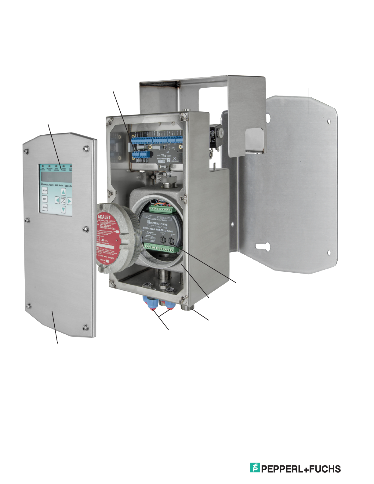
6000 Control Unit
Main unit
I/O Manual
I.S. wiring terminals
User interface controller
(UIC)
Bracket for mounting to the
enclosure
316L stainless steel
(UNS S31603)
Type 4X (IP66) rating
Removable electronics
Explosion-proof/flameproof
enclosure
3/4" conduit for power
connections
Cable glands for I.S. inputs/outputs
6
Page 11
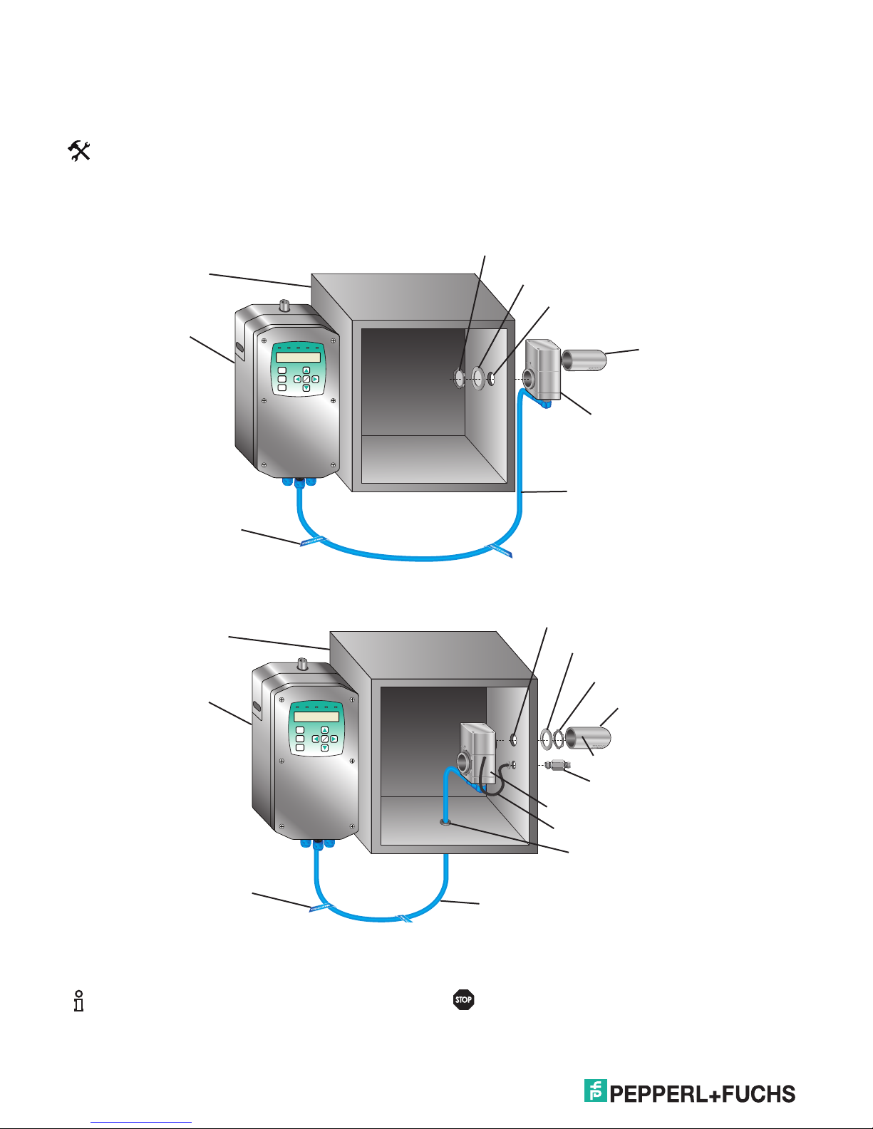
6000 Series Purge/Pressurization System
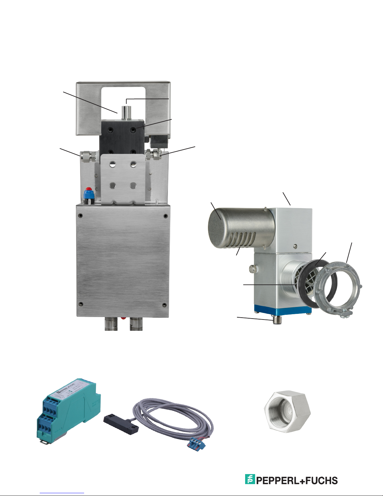
6000 Control Unit
Manifold
I/O Manual
Manifold for
purging and
pressurization
Type 4X (IP66)
ttings for
enclosure ow
Needle valve for
pressurization of enclosure
(requires athead
screwdriver for adjustment)
Manifold with
I.S. solenoid
valve
Connection to
protective gas
supply
Rotating vent cap
Spark arrestor
Vent
The EPV-6000 vent
is required.
Mounts on vertical or horizontal
surface of the enclosure
Lock nut
Seal washer
I.S. temperature hub
Temperature
monitoring/control
accessories
I.S.
temperature
sensor
1.5 " NPT knockout
(Ø 2", 50.8 mm)
M12 (V1) connector
for I.S. connection
to control unit
Conduit plug
7
Page 12

6000 Series Purge/Pressurization System
Warning
Warning
Attention
Warning
Warning
Warning
I/O Manual
Electrical & pneumatic diagrams
Complete 6000 full control unit power
connections (-WH-)
General wiring notes
For power connections to the 6000 control unit and
relay contacts:
1. All applicable local and national wiring codes
MUST be followed when wiring to the unit.
2. Ground wire to be 14 AWG (2.08mm2). Strip
length of ground to mate with pigtail under wire
nut .437" to .5" (11.1mm to 12.7 mm).
3. If a single wire is used, the maximum wire gauge
to the pluggable terminal block is 14 AWG
(2.08mm2).
4. If jumpering from one terminal to another at
pluggable terminal block, the maximum wire
gauge is 16 AWG (1.31mm2) for both wires.
5. Minimum wire gauge to the pluggable terminal
Attention
Warning
Warning
block is 24 AWG (0.20mm2). (Based on
connector, not code. Follow all applicable
codes.)
6. Strip length of wires terminating into the screw
terminals on the pluggable terminal block to be
0.2" to 0.27" (5 mm to 7 mm).
7. Add extra wire length of 1.25" (31.75 mm) past
top of opening in explosion-proof/ameproof box
to pluggable terminal block (allows connector
to be moved out of the way when changing
electronics. Prevents repouring seals).
8. Wires are to be neatly tucked back down past the
lid threads before lid is placed on unit. The wires
must not loop past the high point of the plastic
cover. The wire nut should be tucked in last (If
not, it may be difficult to access when changing
electronics).
9. If using a single conduit seal, the other conduit
on the 6000 control unit will need a cap for
the end of the conduit with appropriate hazloc
certications (A standard 3/4" conduit cap will not
work).
10. Conduit seals with or without the 6000-CC3/4NPT plug must be within 18" (457.2 mm) of
internal explosion-proof/ameproof box, or within
15.25" (387.3 mm) from the end of the conduit
supplied with the 6000 unit.
11. When wiring to the terminal plug, it is easier
to remove the plug, terminate the wires, then
reconnect the plug.
12. When removing the pluggable terminal block, it
is recommended that the electronics module be
supported by pressing down on top of the EPCU
to counteract the lifting force required to remove
the connector.
13. Wire should be copper only, rated 90 °C
Attention
minimum. Minimum of 0.25" (6.3 mm) wire
insulation thickness required.
14. The minimum wire strand in a stranded wire
should have a diameter of 0.1 mm or greater.
15. The 6000-CC-3/4NPT plug is certied to be
used only with the 6000 control unit’s ¾” nipples
coming out of the housing. This plug is not
certied to be used on any other hazardous
location equipment.
16. Ensure that electrical, mechanical, and
pneumatic connections and requirements are
met to operate this system. Please refer to
this manual and applicable standards/codes,
including current editio9n of the EN/IEC 60079-
14. Electrical supply to the purge system shall be
supplied through a switch or circuit breaker and
suitably located and easily reached and must be
marked as the disconnect for the equipment.
1 7. Power must be removed from the system when
the Ex d enclosure cover is off, unless the area is
known to be non-hazardous.
WARNING – To prevent ignition of the ammable
atmospheres, the wiring method must ensure that
if any wire is disconnected and extended to the
opposite terminal, a 2-inch separation must be
maintained.
I.S. wiring notes
For wires going to the explosion-proof/ameproof
box on the I.S. side:
1. The wire strip length is to be between 0.2" and
Attention
0.27" (5 mm and 7 mm).
2. The wire's gauge depends on the number of
connections. Fewer wires allow for heavier
gauge and will still meet the conduit seal ll
requirement. See the applicable standards for ll
requirement.
3. The terminal blocks are rated for a wire size of
16 AWG (1.31 mm2 ) to 28 AWG (0.08 mm2 ).
8
Page 13
6000 Series Purge/Pressurization System
Warning
Warning
Warning
Attention
4. If multiple wires need to land to a single terminal
(e.g., the RS-485 bus), these wires must be
either crimped to a single pin or grouped in an
external junction box with one wire going into the
terminal.
5. The wires must have a minimum insulation
thickness of 0.01" (0.25 mm).
6. Add extra wire length of 1.25" (31.75 mm) past
top of opening in explosion-proof/ameproof box
to pluggable terminal block. (Allows connector
to be moved out of the way when changing
electronics. Prevents repouring seals.)
7. Conduit seal on I.S. wiring side must be within
18" (457.2 mm) of the explosion-proof/ameproof
box.
8. Wire should be copper only, rated 90 °C
minimum.
9. The minimum wire strand in a stranded wire
should have a diameter of 0.1 mm or greater.
I/O Manual
For wires going to the I.S. interface board in the main
housing or to the DIN-rail-mount I.S. board:
1. The wire strip length is to be between 0.16" and
0.24" (4 mm and 6 mm).
2. The terminal blocks are rated for a wire size of
16 AWG (1.31 mm2) to 26 AWG (0.081 mm2).
3. The only terminals that might have multiple
connections are the shield connections.
These must be crimped to a single pin before
connection to the board.
4. If cables are used (recommended for
connections to the vents and UIC), it is
recommended that the cables be shielded.
5. The wires must have a minimum insulation
thickness of 0.01" (0.25 mm).
6. Wire should be copper only, rated 90 °C
Attention
minimum.
7. The minimum wire strand in a stranded wire
should have a diameter of 0.1 mm or greater.
9
Page 14
6000 Series Purge/Pressurization System
Note
Note
IS PWR 1+
IS PWR 1-
IS DATA 1A
IS DATA 1B
IS 1 SHLD
IS PWR 2+
IS PWR 2-
IS DATA 2A
IS DATA 2B
IS 2 SHLD
IS PWR 3+
IS PWR 3-
IS DATA 3A
IS DATA 3B
IS 3 SHLD
INPUT 1-
INPUT 1+
INPUT 2-
INPUT 2+
INPUT 3-
Temp
Module
Vent 1
Vent 2
Inputs
1 thru 4
Enclosure
Prewired
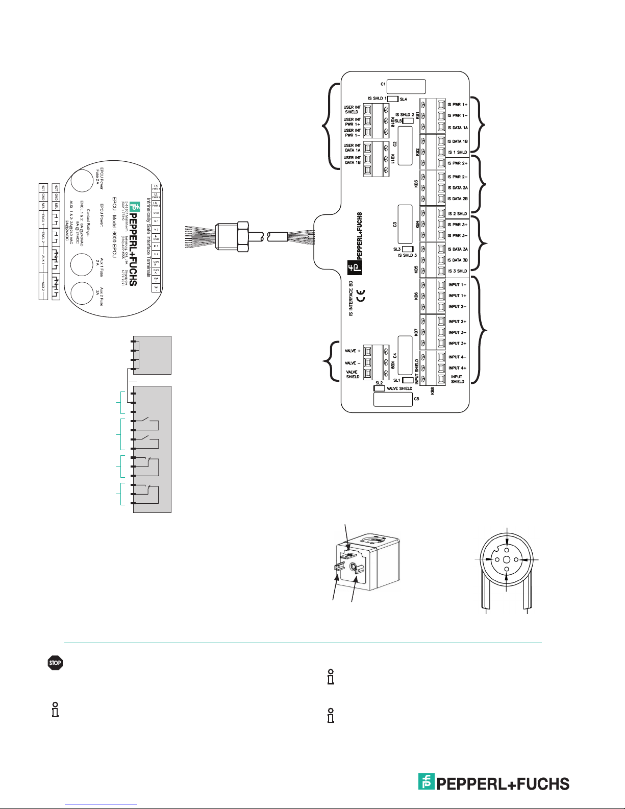
Electrical installation - power and I.S. wiring
I/O Manual
Power to
EPCU
GND
GND
GND
Prewired
L1
GND
N
BK
OR
GN
WT
BK/WT
BL/WT
RD/WT
GN/WT
OR/BK
BL
RD
WT/BK
RD/BK
User interface
connection
(pre-wired)
EPCU I.S. connector
I.S. solenoid valve
from manifold
(pre-wired)
Temperature module
connection
(when Vent 2 is used)
Vent 1 connection
Vent 2 connection or
Temperature Module
connection
Inputs 1 - 4, 5.0 V DC
Contacts
(2) N.O.
Aux
Output 1
(1) SPDT
Aux
Output 2
(1) SPDT
Connector color code for the user interface,
temperature module, and vent:
PWR + BN (brown)
PWR - BU (blue)
DATA_A WH (white)
DATA_B BK (black)
Requires standard explosion-proof seals to
explosion-proof/ameproof enclosure at a
Warning
maximum distance of 18" (457.2 mm).
When removing the terminal block from the
EPCU stack, place your hand on top of the
plastic to support the stack when lifting the
terminal block off the stack.
10
Manifold connection Vent connection
GND
'A' White
+1
-2
'+' Brown
'B' Black
'-' Blue
The EPCU is prewired to the I.S. terminal board.
Note
Both enclosure power contacts are switched at
the same time.
Page 15
6000 Series Purge/Pressurization System
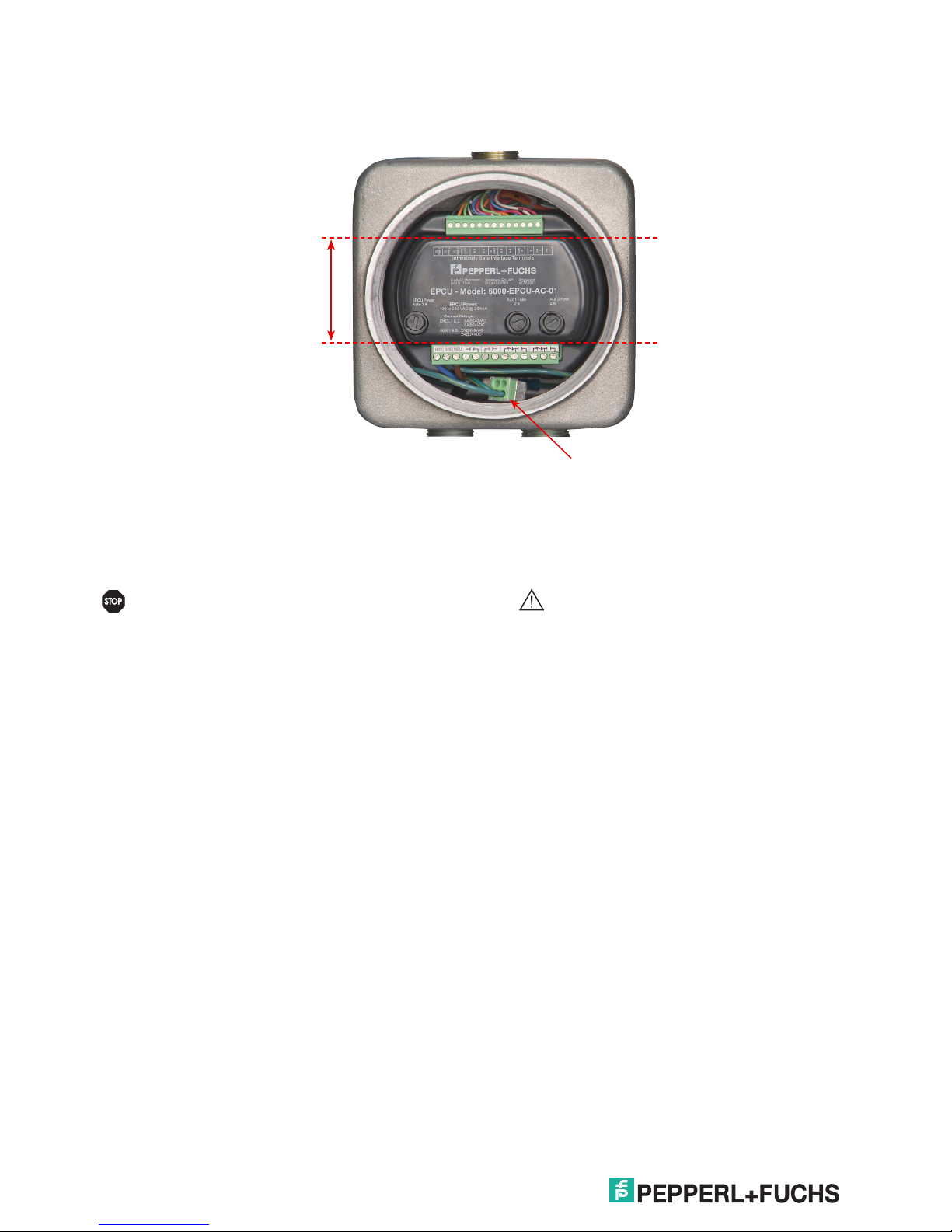
Warning
No wiring is to be in
the area between the
terminals
I/O Manual
I.S. wiring
Non- I.S. wiring
Incoming ground wires
should be terminated into
the supplied wire nut
WARNING: To prevent ignition of the ammable
atmospheres, the wiring method must ensure
that if any wire is disconnected and extended to
the opposite terminal, a 2" (50.8 mm) separation
must be maintained.
EPCU
Maintain a minimum space of 2" (50.8 mm)
between the I.S. wiring and the non - I.S. wiring.
Attention
Make sure that the wiring is neatly tucked into
the explosion-proof housing. Use wire ties if
necessary. As a rule, no wires are to be in the
area between the two terminals, as shown
above.
11
Page 16
6000 Series Purge/Pressurization System
Note
I/O Manual
Pneumatic requirements
Protective gas supply
The protective gas supply to the enclosure system must
be a clean, instrument quality compressed air or inert
gas ltered to a minimum of 40 microns. It must contain
no more than trace amounts of ammable gas, vapor, or
dust.
The protective gas supply compressor intake must
originate in a nonhazardous location. The suction
duct passing through a hazardous location and the
protective tubing and piping must be fabricated from
noncombustible materials suitable for the prevailing
hazardous and environmental conditions.
The protective gas supply provided must be able to
handle the ow and pressure requirements for purging
and pressurization (see page 66, Establishing connection
sizes, lengths & bends).
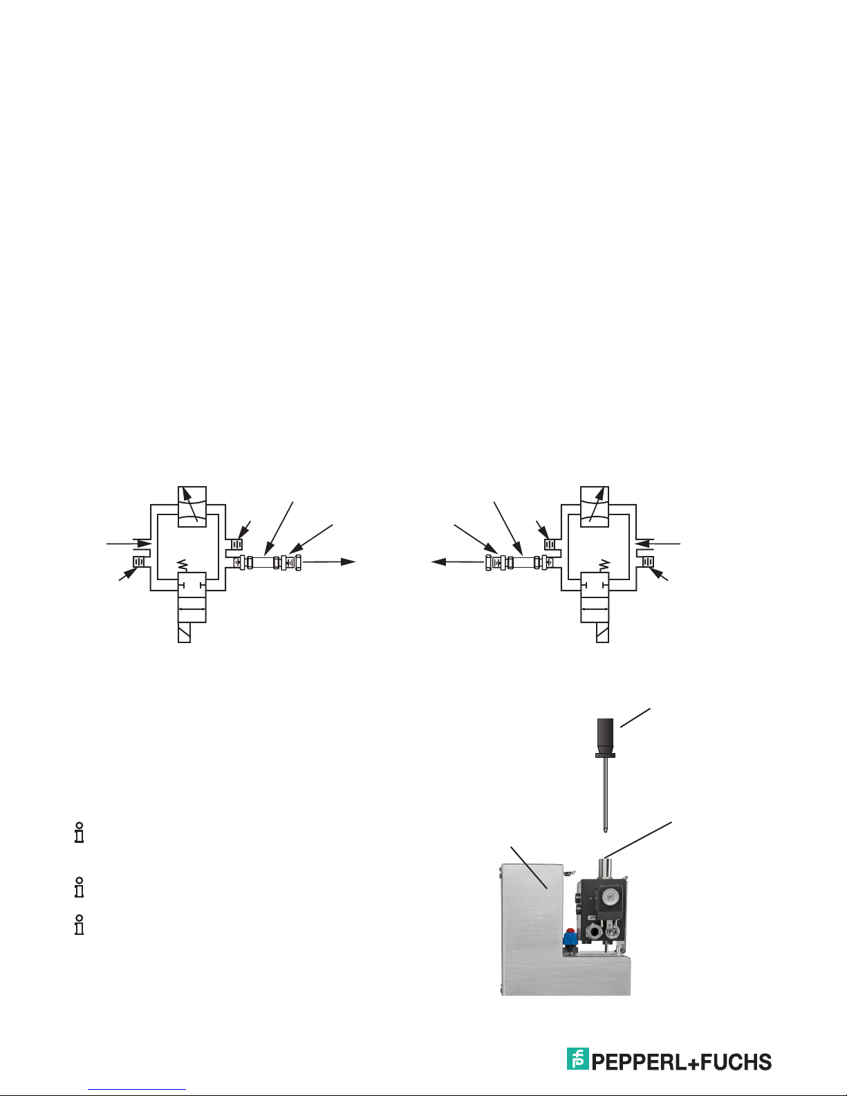
Needle valve
3/8" tubing
Protective
Plug
gas supply
EFC-6-SS
Pneumatic connections
The 6000 series system requires only two pneumatic
connections to the protective enclosure, one for the
exhaust for the vent mounting and the other for the
protective gas supply for purging and pressurization.
The vent requires a single 1 1/2" conduit knockout (Ø2"
[50.8mm]) hole in the enclosure. A lock ring with gasket
for sealing are provided. The control unit for the 6000
series provides a compression tting with a lock ring and
washer connected to a 3/8" tube. All tubing and ttings
are 316L (UNS S31603) stainless steel. A single hole
into the enclosure as noted on the mounting template will
provide the installation for this tting.
For replacement of this tubing use only 3/8" tubing with
wall thickness of 0.035" (0.9 mm).
The 6000 series control unit with the manifold can be
top, bottom, right, or left-hand mounted on the enclosure.
However, the manifold connections may have to be
reversed as shown below.
Needle valve
3/8" tubing
EFC-6-SS
Plug
Protective
gas supply
Plug
Solenoid
valve, EEx io
2/2 way
Supply
to enclosure
Pressurization adjustment
To adjust, use a at head screw driver inserted into the
needle valve of the manifold as shown. Turn clockwise to
decrease the ow, counter-clockwise to increase the ow.
The maximum number of complete rotations allowed is
ve (5).
Diagram shown is without plumbing. See the
diagrams on the following page for plumbing
Note
installation.
Unit must be powered to get a pressure reading.
When delivered, the system is in its default mode
(fully automatic [FA]). It may be easier to adjust
Note
safe pressure in standard (STD) or
semiautomatic (SA) mode so that the system
does not automatically begin purging when
energized.
Supply
to enclosure
MAXIMUM of ve (5) turns
Counterclockwise
rotation
increases ow
6000 control unit
housing
Plug
Solenoid
valve, EEx io
2/2 way
Flathead screwdriver
Clockwise
rotation
decreases ow
Needle valve
in manifold
12
Page 17

6000 Series Purge/Pressurization System
Mounting Instructions
Manifold assembly – left-hand or right-hand mount
Left-hand mount*
*Reverse ttings for
right-hand mount
Protective gas
supply inlet
Protective gas to
enclosure
I/O Manual
3/8" SS tube
(included)
3/8" ferrule tting
(included)
1/4 - 20
at head screws
(4 included)
3/8" SS tube
(included)
3/8" ferrule tting
(included)
Wiring entry
EFC-6-SS
(included)
EFC-6-SS nut
(included)
13
Page 18
6000 Series Purge/Pressurization System
Note
Warning
EPV-6000 vent
Tools:
1 1/2" NPT knockout (Ø 2" [50.8mm] hole ) for
vent
Vent mounted on the outside of the enclosure
Pressurized enclosure
I/O Manual
Locking nut w/grounding screw
(included)
Seal gasket (included)
Ø 2" (50.8 mm)
6000 control unit
I.S. wire tag
(included)
Vent mounted on the inside of the enclosure
Pressurized enclosure
6000 control unit
Vent cap
(included)
EPV-6000
Vent cable (included)
Ø 2" (50.8 mm)
Seal gasket (included)
Locking nut w/o ground
(included)
Vent cap (included)
I.S. wire tag
(included)
Vent is not gravity sensitive and can be installed
in any orientation.
14
Hex screws 0.05"(1.3 mm) (3)
*Bulkhead tting for reference
pressure
EPV-6000
*Reference tube
Cord grip CG-8
(optional)
Vent cable (included)
*Reference tubing and hardware included with EPV-6000-SS models
Cable to the vent is I.S. wiring and must be
properly isolated from other wiring.
Page 19
6000 Series Purge/Pressurization System
6000 Control unit with housing "WH"
Tools:
Appropriate sized drill bits or knockout holes
1 1/16" open end box wrench
Bolts: 1/4-20 (provided),
hole clearance = 0.27" (6.86 mm) diameter
EFC-6-SS (provided):
hole clearance = 0.61" (15.54 mm) diameter
I/O Manual
Seal washer (3 included)
Lock washer (3 included)
1/4-20 pan head bolts
(3 included)
Grounding lug
(included)
Mounting bracket
(included)
6000 control unit
1/4-20 pan head
w/lock washer screws
(4 included)
Ø 0.61" (15.54 mm) hole
Ø 0.27" ( 6.86 mm)
hole (3x)
1/4-20 nuts (3 included)
Locking nut
w/grounding screw
(included)
Seal gasket
(included)
Vent cap
(included)
EPV-6000
Vent cable
(included)
Enclosure
EFC-6-SS nut (included)
EFC-6-SS (included)
1. Drill holes using template. Check the scale if
printing an electronic version.
2. Assemble tubing and tting to control unit. Install
on the "Out" port of the correct side.
3. Bolt mounting plate to the enclosure. Type 4X
washers must be mounted inside the enclosure.
Tighten to 60 – 80 in-lb (16.38 – 18.08 Nm).
3/8" stainless steel tube, 2.5" (65 mm) long (included)
3/8" ferrule tting (included)
4. Put 2 of the mounting screws in the back of the
control unit to align with the key holes in the
mounting plate.
5. Hang the control unit onto the plate. Slide the unit
towards the enclosure so that the EFC-6-SS tting
is in the proper location.
6. Tighten the 2 bolts. Put the other two mounting
bolts in place and tighten.
7. Place the EFC-6-SS bolt in position and tighten.
15
Page 20
6000 Series Purge/Pressurization System
(2.5")
Warning
Tightening unit cover plate
The screws on the unit cover plate must be
tightened in the order shown on the diagram to
the right. The cover plate to the main housing
has positive stops so that the gasket is not over
tightened. Torque screws at 12 in-lb (1.36 Nm).
When rotating the UIC, torque down the 4 screws
at 4 in-lb (0.46 Nm) using a crisscross pattern.
Note
I/O Manual
45
1 2
63
Left-hand mounting template
ø15.5 mm
(.60")
ø 7. 0 mm
(.25")
ø 7. 0 mm
(.25")
ø 7. 0 mm
(.25")
19.0 mm
(.75")
60.0 mm
2.35"
Right-hand mounting template
ø 15.5 mm
(.60")
ø 7. 0 mm
(.25")
189.5 mm
(7.45")
(7.45")
114.5 mm
(4.50")
57.0 mm
(2.25")
189.5 mm
(4.50")
114.5 mm
(2.25")
57.0 mm
2.35"
60.0 mm
(2.5")
ø 7. 0 mm
(.25")
ø 7. 0 mm
(.25")
19.0 mm
(.75")
16
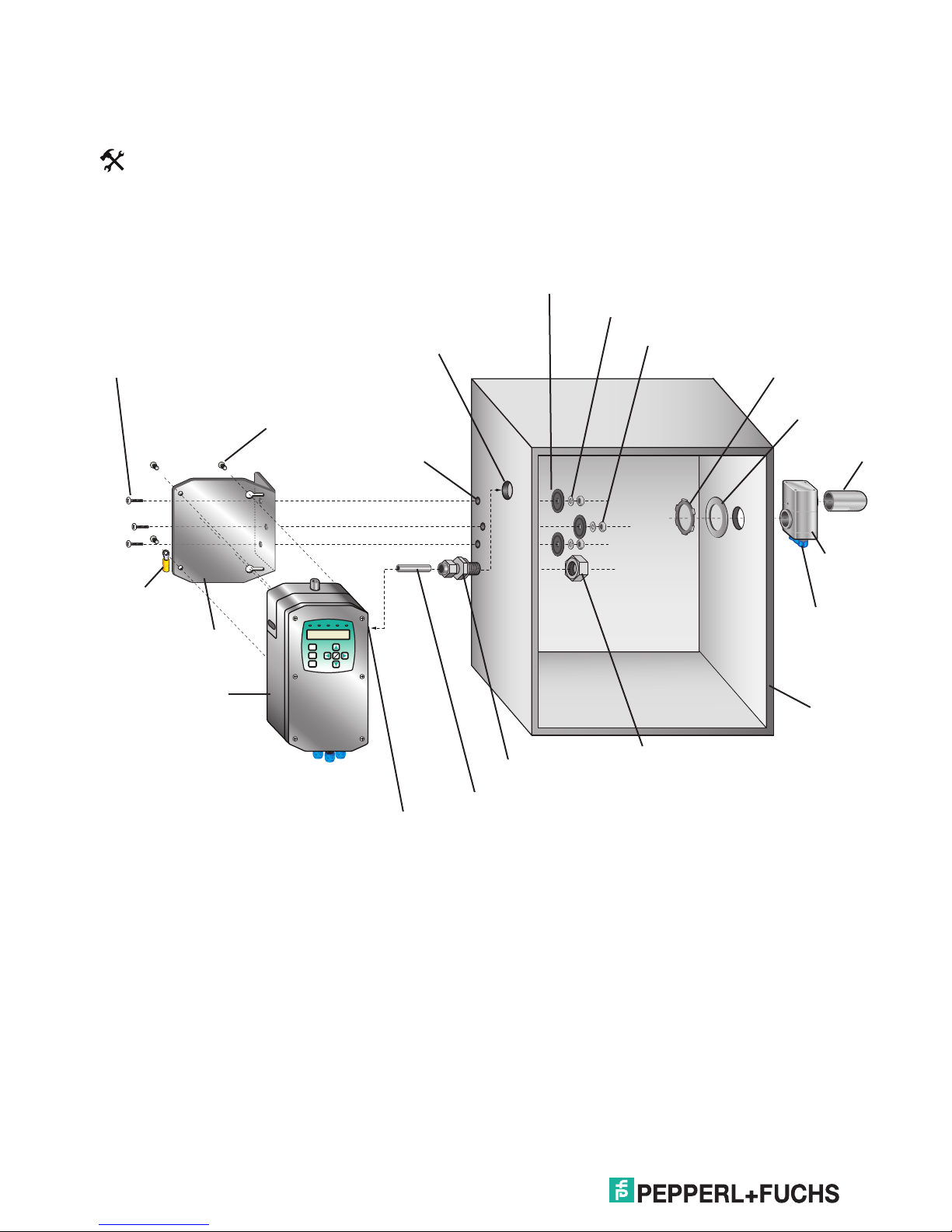
Page 21
6000 Series Purge/Pressurization System
Attention
Attention
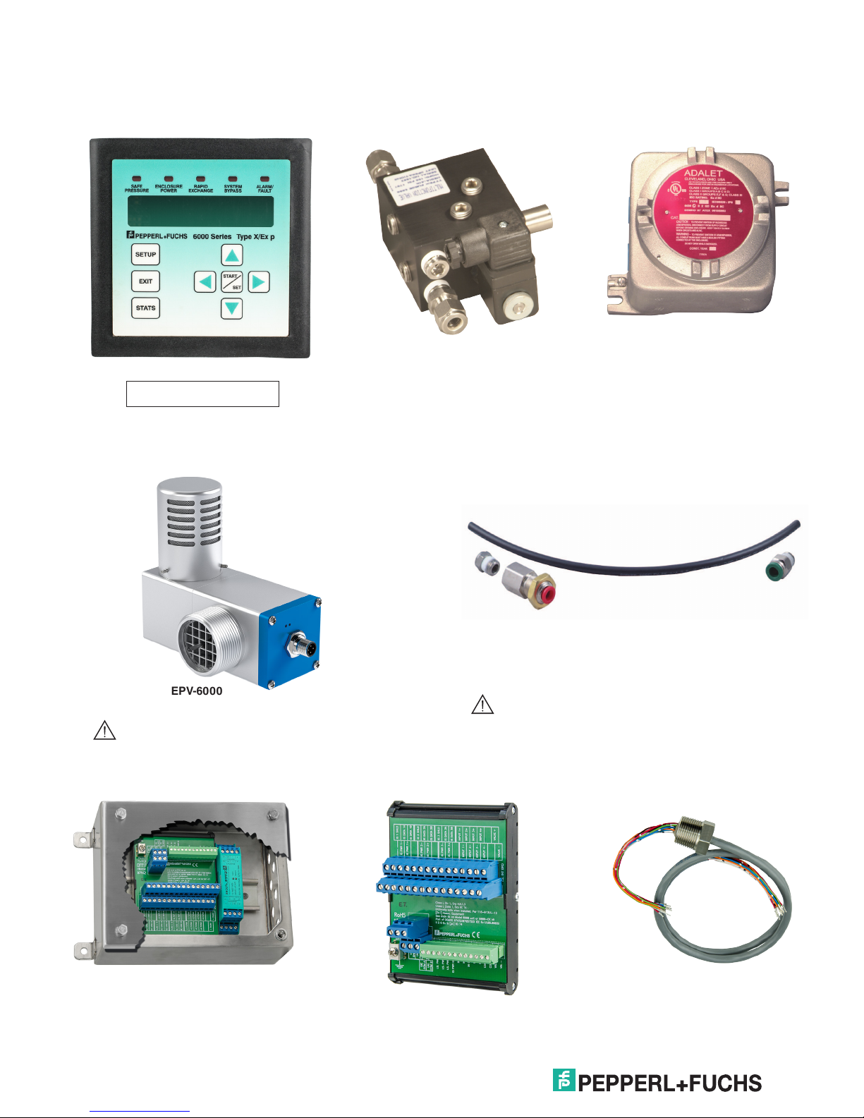
6000 Series component kit
Identication of components
I/O Manual
Optional pneumatic manifold
User interface (Included)
Cannot be mounted in a
hazardous dust environment.
with solenoid (Included)
EPV-6000 vent: required for 6000 control unit / component kit
Atmospheric reference kit (6000-ACC-514482)
for mounting vent inside the enclosure
EPV-6000
The EPV-6000 vent is required.
The reference kit comes with the EPV-6000-SS
vent but must be ordered when mounting the
EPV-6000-AA vent inside the enclosure.
Control unit and explosion-proof/
ameproof enclosure (Included)
6000 series component kit accessories
6000-DPE-01-xxx (Not Included)
Dust-proof enclosure to house the
6000-ISB-01 and 6000-TEMP-01 devices
6000-ISB-01 (Not Included)
DIN-mounted I.S. termination board.
See data sheet for specications
6000-CBLA-ISB-xxxt (Not Included)
Cable assembly for connection from the
6000 EPCU to the 6000-ISB-01. See
data sheet for specic lengths.
17
Page 22
6000 Series Purge/Pressurization System
Warning
Warning
Warning
Warning
Warning
Warning
Warning
Attention
Warning
Warning
I/O Manual
Electrical diagrams
General wiring notes for component kit design
For power connections to the control unit and relay
contacts:
1. All applicable local and national wiring codes
MUST be followed when wiring to the unit.
2. Protective earth wire to be 14 AWG (2.08 mm2).
Strip length of earth to mate with pigtail under
wire nut .437" to .5" (11.1mm to 12.7 mm).
3. If a single wire is used, the maximum wire gauge
to the pluggable terminal block is 14 AWG
(2.08mm2).
4. If jumpering from one terminal to another at
pluggable terminal block, the maximum wire
gauge is 16 AWG (1.31 mm2) for both wires.
5. Minimum wire gauge to the pluggable terminal
Attention
block is 24 AWG (0.20 mm2). (Based on
connector, not code. Follow all applicable codes.)
6. Strip length of wires terminating into the screw
terminals on the pluggable terminal block to be
0.2" to 0.27" (5 mm to 7 mm).
12. When removing the pluggable terminal block, it
is recommended that the electronics module be
supported by pressing down on top of the EPCU
to counteract the lifting force required to remove
the connector.
13. Wire should be copper only, rated 90 °C
minimum.
14. The minimum wire strand in a stranded wire
should have a diameter of 0.1 mm or greater.
15. The 6000-CC-3/4NPT plug is certied to be
used only with the 6000 control unit’s ¾” nipples
coming out of the housing. This plug is not
certied to be used on any other hazardous
location equipment.
16. Ensure that electrical, mechanical, and
pneumatic connections and requirements are
met to operate this system. Please refer to
this manual and applicable standards/codes,
including current editio9n of the EN/IEC 60079-
14. Electrical supply to the purge system shall be
supplied through a switch or circuit breaker and
suitably located and easily reached and must be
marked as the disconnect for the equipment.
7. Add extra wire length of 1.25" (31.75 mm) past
top of opening in explosion-proof/ameproof box
to pluggable terminal block. (Allows connector
to be moved out of the way when changing
electronics. Prevents repouring seals.)
8. Wires are to be neatly tucked back down past the
lid threads before lid is placed on unit. The wires
must not loop past the high point of the plastic
cover. The wire nut should be tucked in last (if
not, it may be difficult to access when changing
electronics).
9. If using a single conduit seal, the other conduit
on the 6000 control unit will need a cap for
the end of the conduit with appropriate hazloc
certications. (A standard 3/4" conduit cap will
not work.)
10. Conduit seals or the 6000-CC-3/4NPT plug must
be within 18" (457.2 mm) of internal explosionproof/ameproof box, or within 15.25" (387.3 mm)
from the end of the conduit supplied with the
6000 unit.
11. When wiring to the terminal plug, it is easier
to remove the plug, terminate the wires, then
reconnect the plug.
1 7. Power must be removed from the system when
the Ex d enclosure cover is off, unless the area is
known to be non-hazardous.
I.S. wiring notes
For wires going to the explosion-proof/ameproof
box on the I.S. side:
1. The wire strip length is to be between 0.2" and
Attention
0.27" (5 mm and 7 mm).
2. The wire's gauge depends on the number of
Attention
connections. Fewer wires allow for heavier
gauge and will still meet the conduit seal ll
requirement. See the applicable standards for ll
requirement.
3. The terminal blocks are rated for a wire size of
16 AWG (1.31 mm2 ) to 28 AWG (0.08 mm2 ).
4. If multiple wires need to land to a single terminal
(e.g., the RS-485 bus) these wires must be
either crimped to a single pin or grouped in an
external junction box with one wire going in to
the terminal.
5. The wires must have a minimum insulation
thickness of 0.01" (0.25 mm).
18
Page 23

6000 Series Purge/Pressurization System
Warning
Warning
6. Add extra wire length of 1.25" (31.75 mm) past
top of opening in explosion-proof/ameproof box
to pluggable terminal block. (Allows connector
to be moved out of the way when changing
electronics. Prevents repouring seals.)
7. Conduit seal on I.S. wiring side must be within
18" (457.2 mm) of the explosion-proof/ameproof
box.
8. Wire should be copper only, rated 90 °C
Attention
For wires going to the I.S. interface board in the
main housing or to the DIN-rail-mount I.S. board:
minimum.
9. The minimum wire strand in a stranded wire
should have a diameter of 0.1 mm or greater.
1. The wire strip length is to be between 0.16" and
0.24" (4 mm and 6 mm).
I/O Manual
2. The terminal blocks are rated for a wire size of
16 AWG (1.31 mm2) to 26 AWG (0.081 mm2)
3. The only terminals that might have multiple
connections are the shield connections.
These must be crimped to a single pin before
connection to the board.
4. If cables are used (recommended for
connections to the vents and UIC), it is
recommended that the cables be shielded.
5. The wires must have a minimum insulation
thickness of 0.01" (0.25 mm).
6. Wire should be copper only, rated 90 °C
Attention
minimum.
7. The minimum wire strand in a stranded wire
should have a diameter of 0.1 mm or greater.
WARNING – The 6000-ISB I.S. termination board
and 6000-TEMP are not certied to operate in
dust-hazardous locations. The 6000-DPE is a
dust-proof enclosure designed only to house
either or both the I.S. termination board and 6000
temperature hub. No other devices are allowed
in the enclosure. This does not apply to the 6000
control unit with housing, a complete unit.
19
Page 24

6000 Series Purge/Pressurization System
Note
Warning
Note
Warning
Enclosure
IS Solenoid
1
2
3
4
5
6
7
8
9
10
11
12
13
Electrical installation - power and I.S. wiring
GND
GND
GND
Temp
Module
(BN)
1
2
3
(BU)
4
5
6
7
8
9
(BK)
10
(WH)
11
12
13
1
Vent 1
2
Vent 2
3
(BU)
4
5
6
7
8
9
(BK)
10
(WH)
11
12
13
Power to
EPCU
Contacts
(2) N.O.
Aux
Output 1
(1) SPDT
Aux
Output 2
(1) SPDT
Prewired
L1
GND
N
IS PWR 1
IS PWR 2
IS PWR 3
GND
In 1
In 2
In GND
In 3
In 4
Com B
Com A
Val +
Val -
Connections from EPCU to eld devices
Connection of the 6000 EPCU to the 6000-ISB-01 DIN-mounted I.S. termination board.
Vents
(BN)
(BN)
I/O Manual
1
2
3
4
5
6
7
8
9
10
11
12
13
User
Inputs 1-4
1
2
3
4
5
6
7
8
9
10
11
12
13
Interface
(BN)
1
2
3
(BU)
4
5
6
7
8
9
(BK)
10
(WH)
11
12
13
BKBK I.S.PWR 1I.S.PWR 1
OROR I.S.PWR 2I.S.PWR 2
GNGN I.S.PWR 3I.S.PWR 3
WTWT GNDGND
BK/WTBK/WT In 1In 1
BL/WTBL/WT In 2In 2
RD/WTRD/WT In GNDIn GND
GN/WTGN/WT In 3In 3
OR/BKOR/BK In 4In 4
BLBL Com BCom B
RDRD Com ACom A
WT/BKWT/BK Val +Val +
RD/BKRD/BK Val -Val -
I.S. Te rmination board connectorEPCU I.S. connector
Valve
1
2
3
4
5
6
7
8
9
10
11
(BN)
12
(BU)
13
Requires standard explosion-proof seals to
explosion-proof/ameproof enclosure at a
maximum distance of 18" (457.2 mm).
When removing the terminal block from the
EPCU stack, place your hand on top of the
plastic to support the stack when lifting the
terminal block.
20
The maximum distance between the control
unit and the termination board is 3 meters.
6000-ISB-… must be installed within an IP20
enclosure. See “conditions of safe use” when
mounting in a dust environment.
Page 25

6000 Series Purge/Pressurization System
Note
Warning
Warning
Note
Component kit installation
User interface
Panel mount (internal mount, for hazardous
area installation, NOT to be used in
Dust, Class II/Zone 21 areas)
Cutout
3.40" x 3.40"
86 mm x 86 mm
Gasket (provided)
User interface
(provided)
I/O Manual
Customer's
enclosure
Mounting bracket
Use a crisscross pattern to tighten the
screws for the UIC bracket. Tighten bolts
3 to 4 in-lb (0.4 Nm). For a good seal,
ensure that the bracket bottoms out on
the enclosure.
Mount the explosion-proof enclosure and valve as
desired. Follow all applicable electrical codes when
required.
When installing panel mount conguration, the
installation must be evaluated for Type 4x rating
by a third party NRTL authorized
certication agency.
1" #6-32 standoff
Enclosure must be made of metal and grounded.
Cutout must be no larger than dimensions
specied in above drawing.
The user interface must be mounted inside the
pressurized enclosure to maintain the
Note
environmental ratings.
21
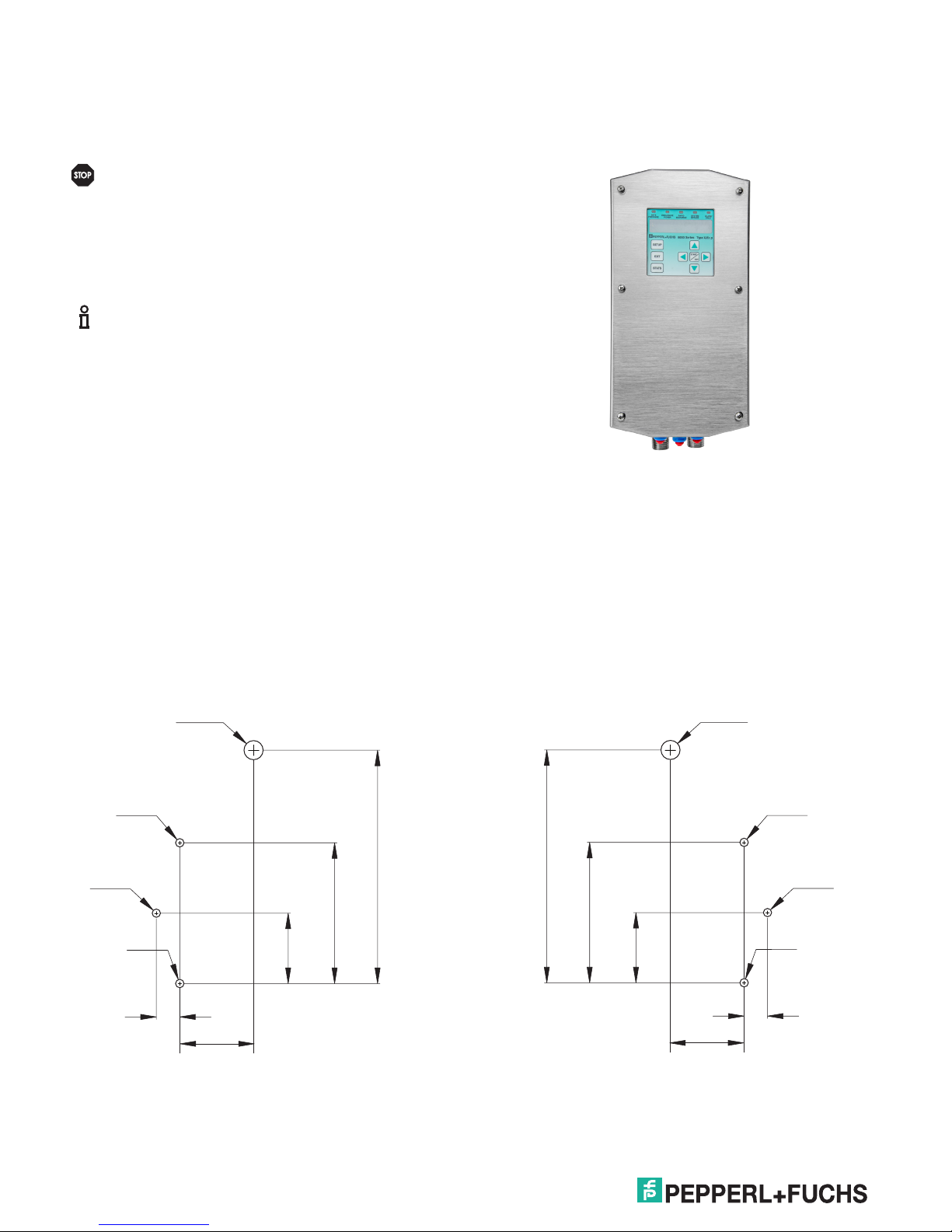
Page 26

6000 Series Purge/Pressurization System
83.0 mm
I/O Manual
User Interface mounting template (panel mount)
53.5 mm
(2.10'')
86.5 mm
(3.40'')
16.5 mm
(0.65'')
4 x
ø 3.5 mm (0.15'')
(0.95'')
24.5 mm
(3.40'')
86.5 mm
(0.95'')
24.5 mm
16.5 mm
(0.65'')
User interface mounting template (external mount)
User
interface
(reference)
(3.25'')
ø4.5 mm (0.15'')
mounting
hole
ø4.5 mm (0.15'')
mounting
hole
51.5 mm (2.05'')
41.5 mm
(1.65'')
ø16.0 mm (0.65'')
connector
clearance
EPCU mounting template
(3.40'')
86.0 mm
(6.75'')
171.5 mm
120.5 mm
(4.75'')
C
L
60.5 mm
(2.40'')
Solenoid mounting template
22.0 mm
(0.85")
38.0 mm
(1.50")
38.0 mm
(1.50")
30.0 mm
(1.20")
10.5 mm
(0.40")
(0.50")
12.5 mm
(1.50")
38.0 mm
19.0 mm
(0.75")
(0.85")
22.0 mm
(0.85")
22.0 mm
(0.80")
20.5 mm
(2.10")
53.5 mm
22
Page 27

6000 Series Purge/Pressurization System
Sequence of events
Turning on power to the enclosure
Door open
input off or
not used
No door
open
I/O Manual
Immediate
shutdown
input off or
not used
Overload/temp
input off or
not used
No immediate
shutdown
No
overload/temp
Vent pressure
>
minimum overpressure
<
maximum pressure
Vent flow
>
flow rate
Good vent
communications
No system
fault
Purge
settings
not changed
progress
Purge
Lock 1
on or
unused
Purge
in
timer
Enable
timer
Timer = 0
Control
power
relay
Lock 2
on or
unused
Door
secure
T
u
r
n
p
o
w
e
r
o
n
Aux relay 1
lock door
Aux relay 1
energized
Aux relay 2
lock door
Aux relay 2
energized
23
Page 28

6000 Series Purge/Pressurization System
Turning off power to the enclosure
Control power
relay input
broken/shorted
Control power
relay input
off
Door open
input
broken/shorted
Door open
input on
I/O Manual
Control
power
relay
Door
open
Overload/temp
input
broken/shorted
Overload/temp
input on
Vent pressure
<
safe pressure
Lost vent
communications
Overload/
temp
Unsafe
pressure
System
fault
Immediate shutdown
input
broken/shorted
Immediate shutdown
input on
Shutdown
timer
Volume
changed
Number of
exchanges
changed
Environment
changed
Timer = 0
Immediate
shutdown
Bypass
is
off
Purge
settings
changed
No bypass
T
u
r
n
p
o
w
e
r
o
f
f
24
Flow rate
changed
Page 29

6000 Series Purge/Pressurization System
Note
I/O Manual
Operation of the 6000 series and component
kit
Operation
The 6000 series consists of the control unit and user
interface mounted in a 316L (UNS S31603) stainless
steel Type 4X (IP66) enclosure with the pneumatic
solenoid valve mounted on the unit. The EPV-6000 series
relief vent is separate and is mounted to the enclosure.
The 6000 series control unit is also available as a kit. The
kit consists of the key components of the system, the
control unit, and the user interface. It does not include
the enclosure. The manifold is an optional item. The
user interface includes a panel-mount bracket so that it
can be panel mounted to the customer’s enclosure. The
pneumatic valve for the protective gas can be supplied by
the customer. The EPV-6000 relief vent is still required.
The components of the 6000 series control unit, with
'-WH-' housing, are listed below:
• EPCU mounted in an explosion-proof/ameproof
enclosure
• I.S. user interface with display and cable
• I.S. termination board (not included with "CK" kit
version)
• Manifold with I.S. solenoid valve (not included with
"CK" kit version)
• Flush mount Type 4X IP66 tting for protective gas
supply to enclosure with tube attached
• Type 4X cable glands for I.S. wiring to I.S. inputs,
vents, and temperature modules
• 3/4" pipe nipples for power wires
The components of the 6000 series component kit are
listed below:
• Control unit and explosion-proof/ameproof
enclosure
• 6000-UIC-01 user interface
• SMK-600-CK mounting hardware for 6000-UIC-01
• One 5m (16.5 ft.) quick disconnect cable for 6000UIC-01
• 6000-MAN-DV-01 pneumatic manifold w/ solenoid
(optional)
• EFC-6-SS ush mount connector
The 6000 series control unit and vent can be universally
mounted to the customer's enclosure. Top, bottom, right-,
or left-side mounting can be completed with only one
control unit and vent. Mounting conguration does not
need to be designated when ordering. One unit is used
for enclosure sizes up to 450 ft3 (12.7 m3).
Optional accessories are available to make the
component kit easier to install. The 6000-ISB-01 I.S.
DIN-mounted termination board and 6000-CBLA-ISB-xxx
cable harness allow easy connection to the EPCU of the
control unit.
Electronic power control unit – EPCU
The EPCU houses the redundant microprocessors,
enclosure power contacts, (2) auxiliary contacts, power
supply module, galvanically isolated barriers for the
inputs, vent(s), and temperature modules. The EPCU
is easy to remove and install into the explosion-proof
enclosure that houses it.
• 316L (UNS S31603) stainless steel Type 4X
enclosure for the 6000 series controller. (Not
included with the component kit.)
The components of the EPV-6000 vent:
• EPV-6000 vent with stainless steel spark arrestor
screen
• 1½" lock nut with grounding lug and gasket for
attachment of vent to customer’s enclosure
• One 5m (16.4 ft.) quick disconnect cable; for
connection to I.S. termination board inside 6000
series control unit.
If ordering a stainless steel vent, an atmospheric
reference kit is included for internal mount.
The EPCU is available in 20 ... 30 VDC or
100...250 VAC units. The enclosure power contacts are
force-guided safety relays. The auxiliary contacts can be
user congured for different functions, depending on user
requirements.
User interface controller – UIC
The 6000 series is user programmable for many of the
congurable options available. This is done with the
intrinsically safe user interface on the face of the unit,
which can also be remote mounted. The user interface
contains a 2 x 20 LCD that allows programming through
a set of buttons on the menu-driven unit. All conguration
and options are programmed through this unit. There are
also (5) LEDs for easy visual indication of operation:
• Safe pressure – This turns on (blue) when safe
pressure is achieved inside the enclosure.
25
Page 30

6000 Series Purge/Pressurization System
Note
Note
I/O Manual
• Enclosure power – This is (red) when the
enclosure power is off, and (green) when
enclosure power is on. The enclosure power can
be on only after a successful purge and a safe
pressure is achieved. The bypass option allows
power to remain on if safe pressure is lost.
• Rapid Exchange® – The rapid exchange or purging
ow rate turns on (blue) when the ow rate is
measuring proper ow.
• System bypass – This turns on (yellow) when the
system bypass is active. This should be used only
when the area around the enclosure is known to
be safe.
• Alarm fault – The (red) LED blinks when any alarm
input is detected and is solid when there is an
internal system fault.
Pneumatic manifold with I.S. solenoid
• Manifold with I.S. solenoid valve: The manifold
system is mounted on the 6000 control unit
providing a needle valve to set enclosure pressure
and an I.S. solenoid valve that is used for purging
(Rapid Exchange). Power for the I.S. solenoid
valve is provided by the EPCU and is galvanically
isolated. Regulated instrument-grade air or
nitrogen is required.
rate measurement from the EPV-6000 vent is 7 SCFM
(198l/m), the EPCU will use 5 SCFM (141l/m) as the
ow rate for evaluation. The ow rate measurement steps
and corresponding enclosure pressures are as follows:
EPV-6000-XX-01, 02
5 SCFM @ 1.5” wc, (141 l/min @ 3.7 mbar)
12 SCFM @ 2.0” wc, (340 l/min @ 5.0 mbar)
20 SCFM @ 2.7” wc, (565 l/min @ 6.7 mbar)
30 SCFM @ 4.1” wc, (850 l/min @ 10.2 mbar)
EPV-6000-XX-03, 04
5 SCFM @ 2.1” wc, (141 l/min @ 5.2 mbar)
12 SCFM @ 2.6” wc, (340 l/min @ 6.5 mbar)
20 SCFM @ 4.1” wc, (565 l/min @ 10.2 mbar)
30 SCFM @ 5.3” wc, (850 l/min @ 13.2 mbar)
EPV-6000-XX-05, 06
5 SCFM @ 1.5” wc, (141 l/min @ 4.5 mbar)
12 SCFM @ 2.9” wc, (340 l/min @ 7.3 mbar)
The following parameters must be entered for
the purge time:
• Enclosure volume
• Number of exchanges.
Minimum purge time is 2 min
The 6000 series unit can be ordered without the manifold
so that customers can use their own method or valves
for purging and pressurization. If a third-party electronic
valve is used, the valve must be certied and installed in
accordance with the hazardous location where the unit is
operating. The use of the 6000 series manifold unit allows
easy and correct installation of the system.
Requirements for purging/pressurization
Certications allow the 6000 series to be used on
enclosures in gas, dust, or both gas and dust hazardous
atmospheres. Gas atmospheres require the purging of
the enclosure. Dust atmospheres require the physical
removal of all the dust that collects inside. Both gas and
dust atmospheres require the following: 1) removing the
dust, 2) sealing the enclosure, and then 3) purging the
enclosure.
After these sequences, the pressure within the enclosure
is above the minimum level. The equipment within the
enclosure can then be energized.
Purge timing
When using the 6000 series in a gas or gas and dust
location, the time for purging an enclosure can be based
either on a known purge rate and time (xed purge
time), or based on the ow rate being measured from
the vent (dynamic purge time). Both methods base the
time on the ow measurement at the vent, and complete
the process in steps. The EPCU will take the readings
from the vent and use the appropriate reading (listed
below) as the usable ow rate. For example, if the ow
Fixed purge time
If the purge time must be held to a specic time, then this
time is based on the known enclosure volume, number
of volume exchanges, and ow rate through the vent.
If the ow rate is below the required minimum, then the
purging cycle will reset and will not start until the ow
rate is above the selected rate. This setup does not
allow purge ow to go below the value required and will
not recalculate the time for purging if it goes above the
required purge rate. This measurement method is the
same type as was used in our previous system, the 4000
series. The actual time is calculated by the EPCU.
Dynamic purge time
Dynamic purge time allows the purge time to be updated
based on the purge ow through the vent. This method is
not dependent on a constant ow from the protective gas
source. It bases the purge time on the measured ow and
not a set ow. This is very useful when the protective gas
supply pressure varies throughout the purging cycle or
when it may vary from one installation to another.
The purge time will be based on the measurement of
the vent and evaluation of this measurement from the
EPCU. This allows recalculation of the time based on
this measurement. During the dynamic purge time, the
user interface will display the purge time in a percentage
starting with 0% and ending with 100% (purge time
complete).
26
Page 31

6000 Series Purge/Pressurization System
Note
Note
Note
I/O Manual
Purging modes
Purging start-up can be set in 3 different modes:
• STD – Standard mode requires the operator to
engage the manifold solenoid valve manually
when purging and manually disengage when a
successful purging is complete.
• SA – Semi-automatic mode requires the operator
to engage the manifold solenoid valve manually
when purging. The EPCU will automatically
disengage when a successful purging is complete.
• FA – Fully-automatic mode will automatically
engage the manifold solenoid valve when safe
pressure is detected and will automatically
disengage when a successful purging is complete.
This is the factory default setting.
The minimum purge time is 1 minute.
During the purging cycle, when the enclosure
pressure reaches 0.25" wc [(6.4 mm wc),
(0.625 mbar), (62 pa)] or higher, there will be
a 5 second delay before the rapid exchange
solenoid valve is activated. If the ow is enough
through the vent to satisfy the required ow rate
setting, then the timer will begin after 1 min.
The update of the timer is in increments of 1 min
in the Fixed Purge Time and % completed in the
Dynamic Purge Time.
Pressure as Input
In the programming menu under "INPUT SETTINGS"
for the optional pressure control. The pressure control is
achieved within the enclosure by opening and closing a
digital valve or manifold on the 6000 control unit. These
two internal pressure set points can be controlled by the
manifold or an outside source for pressure. The pressure
function can manage the control outputs 1 or 2, or the
control valve (manifold valve).
• The "ON PRESSURE" is the lowest pressure you
want in the enclosure and will start the control
action on when pressure goes below this value.
• The "OFF PRESSURE" is when the valve shuts
off. When the pressure is between these two
values, nothing will happen.
• The "ON PRESSURE" function is active until the
"OFF PRESSURE" is reached
This function does not operate during purging
cycle and only operates after purging and
pressurization.
The "ON PRESSURE" always has to be lower
than the "OFF PRESSURE". This cannot
be reversed.
PRESSURE AS INPUT
on
Control action
time
off
Control action
OFF PRESS
Set PRESS
ON PRESS
off
Control action
I.S. Inputs 1 - 4
There are (4) intrinsically safe inputs for activation
of various outputs and actions by the EPCU. These
inputs only accept a dry contact for activation and are
supplied by the EPCU’s galvanically isolated barrier. The
congurations of the inputs for various actions are done
through the user-interface controller. Only one function
can operate per input. The intrinsically safe inputs can
be congured through the UIC to activate the auxiliary
relays, energize the Rapid Exchange valve, de-energize
the enclosure contacts, and shut the system down, as
well as other actions and outputs. To monitor wiring, the
SRM-6000 (sensor resistor module, not required, ordered
separately) can be added to detect shorts or breaks in
the inputs' wiring to the contacts.
Outputs
Enclosure 1 and Enclosure 2
There are (2) normally open dry contacts for the
enclosure power that can be energized only after a
successful purging and a minimum enclosure pressure
is maintained. Loss of pressure will cause the contacts
to de-energize unless the shutdown timer is activated or
bypass mode is implemented. These contacts operate
simultaneously.
Auxiliary 1 and Auxiliary 2
Also available are the Auxiliary 1 and Auxiliary 2 SPDT
dry contact outputs. The auxiliary outputs are user
congurable using the user-interface controller and can
control various inputs or various conditions such as low
pressure, loss of pressure, bypass implemented, rapid
exchange valve on, enclosure above maximum pressure
setting, etc. Both enclosure contacts and auxiliary
contacts are forced-guided safety relays for functional
safety.
27
Page 32

6000 Series Purge/Pressurization System
Warning
Warning
Note
Note
Note
I/O Manual
Do not use auxiliary contact for power to
enclosure(s).
If powering auxiliary equipment with
auxiliary1 or auxiliary2 outputs, the wiring
methods used must be suitable for the
hazardous area.
Temperature Inputs
The 6000-TEMP-01 temperature hub and 6000-TSEN-01
external temperature sensor(s) are designed to work only
with the 6000 purge and pressurization system.
An averaging or maximum temperature input reading
from the sensor(s) is used to control a solenoid valve or
activate the auxiliary relay to cool or heat the enclosure,
or warn of temperature problems.
In the programming menu, under "SENSOR SETUP",
"EXT SENSOR COUNT", you can congure up to 3
sensors per temperature hub. Each temperature hub has
one embedded temperature sensor. In the programming
menu under "INPUT SETTINGS" you will select the
"HUB". This must be selected if you want to include the
hub as a sensor input.
You may not want to include the temperature as
an input if the sensor is not located near the
device or process you are tracking the
temperature of.
Once a "CONTROL ACTION" is selected, then select
"SETPOINT TYPE" for the "AVERAGE" or "SINGLE PT".
If using more than one (1) sensor, you may want
the control action to occur during the peak or
average temperature of the sensors.
"ON SET POINT" and "OFF SET POINT" are the
temperatures for the control action.
The "ON SET POINT" can be greater than the
"OFF SET POINT"
TEMPERATURE INPUT
on
Control action
time
off
Control action
MAX
Temperature
MIN
off
Control action
High Temperature Control
EPV-6000 I.S. relief vent
The EPV-6000 vent exhausts excess pressure from the
enclosure when the enclosure pressure exceeds the
breaking pressure of the vents relief mechanism. This
pressure and ow is measured during operation. The
6000 series vent has a pressure transducer and thermal
ow sensor that is connected to the 6000 EPCU and is
intrinsically safe through the galvanic isolation barrier
within the EPCU. The measurement of the ow is always
at the exhaust of the pressurized enclosure; therefore,
the vent is located on the enclosure(s) such that it is
venting to the atmosphere.
When using the complete 6000 series system, the
vent is connected to the I.S. termination board using
the M12 (V1) connector and cable that come with the
vent. If using the 6000 series component kit, the vent is
connected to the EPCU as shown in the diagram on page
19 (brown wire to terminal 2, blue wire to terminal 4,
black wire to terminal 10, white wire to terminal 11). The
EPV-6000 vent can be mounted vertically or horizontally
and is not gravity dependent. For corrosive environments,
the EPV-6000 vent can be ordered with a stainless steel
cap so that the body of the vent can be mounted in the
enclosure with only the stainless steel cap exposed to the
outside environment.
TEMPERATURE INPUT
on
Control action
time
MAX
Temperature
MIN
off
Control action
Low Temperature Control
28
off
Control action
LEDs for the vent
LED indication for the vent is green for power and amber
for second address vent which is used in two-vent / oneEPCU systems.
Page 33

6000 Series Purge/Pressurization System
I/O Manual
Set-up procedures of 6000 series system
1. Ensure that electrical, mechanical, and pneumatic
connections and requirements are met to operate
this system. Please refer to this manual and
standards for explanation of requirements.
2. Apply power to the 6000 series system.
3. (Step 3 is for initial set-up of the system.) The
factory default of the 6000 control unit is SA. To
adjust the programming of the system, please see
page 31 ("Programming menu") for instructions.
4. Verify that the "enclosure pressure control valve"
stem is closed before applying pressure to the
manifold.
5. Turn on the protective gas supply to the 6000
series system inlet on the manifold. Inlet pressure
should be below 120 psig (8.2 bar).
6. Larger cabinets may take longer to pressurize.
Put the system in SA or STD mode for this
procedure. Select the user interface display so that
the enclosure pressure is showing. This should
be reading less than 0.1" wc [(2.54 mm wc),
(.25 mbar), (24.9 Pa)]. Slowly open the needle
valve until you can feel air venting at the exhaust.
Do not exceed 1.5" wc [(38.10 mm wc),
(3.75 mbar), (374 Pa)].
7. If air is not exhausting at the vent, check for any
obstructions or improper installation.
8. The system is ready to operate.
• If the safe pressure drops below 0.25" wc
[(6.4 mm wc), (.625 mbar), (62 Pa)], power to
the enclosure will be disconnected unless a time
delay for shutting off power is implemented (see
the requirements for time delay of power shut-off).
• To energize the enclosure again, repeat the
procedure.
Dust hazardous location
• Enclosure must be cleaned of all combustible dust.
Purging cannot be done to clean combustible dust
out of enclosure.
• Enclosure is immediately sealed upon removal of
combustible dust.
• Pressure is set to a value above a minimum of
0.65" wc [(16.5 mm wc), (1.6 mbar), (162 Pa)],
or the set value from the user input.
• With the pressure in the enclosure above 0.65" wc
[(16.5 mm wc), (1.6 mbar), (162 Pa)], the
enclosure is considered safe, and power to the
enclosure can be energized.
• If the safe pressure drops below 0.65" wc
[(16.5 mm wc), (1.6 mbar), (162 Pa)], the power
to the enclosure will be disconnected, unless a
time delay for shutting off power is implemented
(see the requirements for time delay of power
shut-off).
• To energize the enclosure again, repeat the
procedure.
Operation of the 6000 series system
Gas hazardous location
• Follow "Set-up procedures of 6000 series system"
• Enclosure is sealed.
• Pressure is set to a value above a minimum of
0.25" wc [(6.4 mm wc), (.625 mbar), (62 Pa)], or
the set value from the user input.
• Depending on how the purging mode is selected,
purging the enclosure is required.
• After a successful purging, with the pressure in
the enclosure above 0.25" wc [(6.4 mm wc),
(.625 mbar), (62 Pa)], the enclosure is considered
safe, and power to the enclosure can be
energized.
29
Page 34

6000 Series Purge/Pressurization System
Note
Note
I/O Manual
Dust and gas hazardous location
• Enclosure must be cleaned of all combustible dust.
• Enclosure is sealed.
• Pressure is set to a value above a minimum of
0.65" wc [(16.5 mm wc), (1.6 mbar), (162 Pa)],
or the set value from the user input.
• Depending on how the purging mode is selected,
purging the enclosure is required.
• After a successful purging, with the pressure in
the enclosure above 0.65" wc [(16.5 mm wc),
(1.6 mbar), (162 Pascal)], the enclosure is
considered safe, and power to the enclosure can
be energized.
• If the safe pressure drops below 0.65" wc
[(16.5 mm wc), (1.6 mbar), (162 Pa)], the power
to the enclosure will be disconnected, unless a
time delay for shutting off power is implemented
(see the requirements for time delay of power
shut-off).
Start-up label located on 6000 series control
unit
• To energize the enclosure again, repeat the
procedure.
The combination of dust and gas requires the cleaning
and sealing of the enclosure to clear out the dust
hazard(s) and purging the enclosure to clear out the gas
hazard(s). After these sequences, the enclosure can be
energized. However, the pressure during operation must
be sufficient to keep out the worst case hazard in the
atmosphere/environment. In this application, dust.
Refer to "Conditions of Safe Use"
EN60079-2 and IEC 60079-2 do not cover both
gas and dust hazardous atmospheres. The
6000 system provides a solution for both at the
same time but would have to be evaluated by the
certication bodies for approval.
30
Page 35

6000 Series Purge/Pressurization System
Note
Note
Note
The user interface
RAPID EXCHANGE LED (blue)
On: rapid exchange ow is above min
I/O Manual
On (green): enclosure power relays energized
ENCLOSURE POWER LED
Off (red): enclosure power relays deenergized
SAFE PRESSURE LED (blue)
On: minimum over pressure
SETUP: to enter setup mode
EXIT: to exit a menu
STATS: history and
up-to-date information
SYSTEM BYPASS LED (yellow)
On: bypass is initiated
ALARM FAULT LED (red)
Blinking: any alarm input detection
Solid: 6000 series internal system fault
Display: 2 x 20 LCD
with backlight screen
Arrow keys: for scrolling
through the menus
and setting passwords
START/SET: for menu
entry selection
To cycle power to the unit, press the EXIT, Left
Arrow, START/SET, and Right Arrow keys at the
same time. This will cycle power to the EPCU
without physically removing power. This re-cycle
feature will de-energize the relays of the EPCU
and reset the unit.This feature does not affect
any of the settings in the menus of the EPCU.
To turn LCD back light on and off, press the
left and right arrow keys at the same time. The
setting remains through the power cycles.
To change the LCD contrast, press the up and
down arrow keys at the same time. This will take
you to the contrast screen. Then use the up and
down arrow keys to adjust the contrast. Once the
contrast level is selected, press the START/SET
key to save setting. This setting remains through
power cycles.
31
Page 36

6000 Series Purge/Pressurization System
Programming menu
SETUP — PASSWORD — PURGE SETTINGS —
— UNITS —
— INPUT SETTINGS —
— OUTPUT SETTINGS —
— PASSWORD —
— LANGUAGE —
I/O Manual
— BYPASS CONTROL —
— RESTORE DEFAULTS —
32
Page 37

6000 Series Purge/Pressurization System
Purge settings
PURGE
SETTINGS
— ENCLOSURE
VOLUME
— NUMB OF
EXCHANGES.
— PURGE FLOW — 5 — SETTING CORRECT
— USER DEFINED — SETTING CORRECT
— 4 - 19 — SETTING CORRECT
— 12 — SETTING CORRECT
— 20 — SETTING CORRECT
— 30 — SETTING CORRECT
— DYNAMIC — SETTING CORRECT
I/O Manual
Y/N
Y/N
Y/N
Y/N
Y/N
Y/N
Y/N
— VENT FLOW
CONTROL
— ENVIRONMENT — GAS, DUST, BOTH — SETTING CORRECT
— PRESSURES — MAX OVER PRESSURE — XX.XX — SETTING CORRECT Y/N
— TIMERS — PURGE TIMER — READ ONLY - FIXED
— OPERATION
MODE
— ONE VENT — SETTING CORRECT
Y/N
— 2 VENTS ADD FLOWS — SETTING CORRECT
Y/N
— 2 VENTS LEAST FLOW — SETTING CORRECT
Y/N
Y/N
— LOW PRESSURE — XX.XX — SETTING CORRECT Y/N
— MIN OVER PRESSURE — XX.XX — SETTING CORRECT Y/N
— SETTING CORRECT Y/N
TIME.
— SHUTDOWN TIMER — 0 - 300 SEC. — SETTING CORRECT Y/N
— UNLOCK DOOR TIMER — 0 - 300 MIN. — SETTING CORRECT Y/N
BYPASS OFF TIMER 0 - 300 SEC. SETTING CORRECT Y/N
— STD, SA, FA — SETTING CORRECT
Y/N
Units
UNITS — ENGLISH OR METRIC — SETTING CORRECT Y/N
33
Page 38

6000 Series Purge/Pressurization System
Inputs
INPUT SETTINGS — INPUT 1 — INPUT 1
FUNCTION
— DISABLED — SETTING CORRECT Y/N
I/O Manual
— INPUT 1
FUNCTION
— SRM — SRM YES,NO — SETTING CORRECT Y/N
— INVERT INPUT — INVERT YES, NO — SETTING CORRECT Y/N
— INPUT 2 — INPUT 2
FUNCTION
— INPUT 2
FUNCTION
— IMMEDIATE SHTDN — SETTING CORRECT Y/N
— DOOR OPEN ALARM — SETTING CORRECT Y/N
— OVERLOAD — SETTING CORRECT Y/N
— CONTROL PWR
RELAY
— CONTROL OUTPUT 1— SETTING CORRECT Y/N
— CONTROL OUTPUT 2— SETTING CORRECT Y/N
— CONTROL VALVE — SETTING CORRECT Y/N
— SYSTEM BYPASS — SETTING CORRECT Y/N
— DISABLED — SETTING CORRECT Y/N
— IMMEDIATE SHTDN — SETTING CORRECT Y/N
— DOOR OPEN ALARM — SETTING CORRECT Y/N
— OVERLOAD — SETTING CORRECT Y/N
— CONTROL PWR
RELAY
— CONTROL OUTPUT 1— SETTING CORRECT Y/N
— SETTING CORRECT Y/N
— SETTING CORRECT Y/N
34
— CONTROL OUTPUT 2— SETTING CORRECT Y/N
— CONTROL VALVE — SETTING CORRECT Y/N
— SRM — SRM YES,NO — SETTING CORRECT Y/N
— INVERT INPUT — INVERT YES, NO — SETTING CORRECT Y/N
Page 39

6000 Series Purge/Pressurization System
I/O Manual
— INPUT 3 — INPUT 3
FUNCTION
— INPUT 3
FUNCTION
— SRM — SRM YES,NO — SETTING CORRECT Y/N
— INVERT INPUT — INVERT YES, NO — SETTING CORRECT Y/N
— INPUT 4 — INPUT 4
FUNCTION
— INPUT 4
FUNCTION
— DISABLED — SETTING CORRECT Y/N
— IMMEDIATE SHTDN — SETTING CORRECT Y/N
— DOOR OPEN ALARM — SETTING CORRECT Y/N
— OVERLOAD — SETTING CORRECT Y/N
— CONTROL PWR
RELAY
— CONTROL OUTPUT 1 — SETTING CORRECT Y/N
— CONTROL OUTPUT 2 — SETTING CORRECT Y/N
— CONTROL VALVE — SETTING CORRECT Y/N
— DISABLED — SETTING CORRECT Y/N
— IMMEDIATE SHTDN — SETTING CORRECT Y/N
— DOOR OPEN ALARM — SETTING CORRECT Y/N
— OVERLOAD — SETTING CORRECT Y/N
— CONTROL PWR
RELAY
— CONTROL OUTPUT 1 — SETTING CORRECT Y/N
— CONTROL OUTPUT 2 — SETTING CORRECT Y/N
— CONTROL VALVE — SETTING CORRECT Y/N
— SETTING CORRECT Y/N
— SETTING CORRECT Y/N
— SRM — SRM YES,NO — SETTING CORRECT Y/N
— INVERT INPUT — INVERT YES, NO — SETTING CORRECT Y/N
35
Page 40

6000 Series Purge/Pressurization System
I/O Manual
— PRESS AS
INPUT
— TEMP INPUT — SENSOR SETUP — EXT SENSOR
— PRESS FUNCTION — SETTING CORRECT
Y/N
— PRESS FUNCTION — DISABLED — SETTING CORRECT
— CONTROL OUTPUT 1— SETTING CORRECT
— CONTROL OUTPUT 2— SETTING CORRECT
— CONTROL VALVE — SETTING CORRECT
— ON PRESSURE — ON PRESSURE
XX.X IN WC — SETTING CORRECT
— OFF PRESSURE — OFF PRESSURE
XX.X IN WC — SETTING CORRECT
COUNT
— USE HUB SENSOR — HUB YES, NO — SETTING CORRECT Y/N
Y/N
Y/N
Y/N
Y/N
Y/N
Y/N
— XX — SETTING CORRECT Y/N
— TEMP INPUT 1 — TEMP FUNCTION — DISABLED — SETTING CORRECT Y/N
— TEMP FUNCTION — IMMEDIATE SHTDN — SETTING CORRECT Y/N
— DOOR OPEN ALARM — SETTING CORRECT Y/N
— OVERLOAD — SETTING CORRECT Y/N
— CONTROL PWR
RELAY
— CONTROL OUTPUT 1 — SETTING CORRECT Y/N
— CONTROL OUTPUT 2 — SETTING CORRECT Y/N
— CONTROL VALVE — SETTING CORRECT Y/N
— ALARM — SETTING CORRECT Y/N
— SETPOINT TYPE — *AVERAGE SINGLE
— ON SET POINT — XX °F
— OFF SET POINT — XX °F
PT
— SETTING CORRECT Y/N
36
Page 41

6000 Series Purge/Pressurization System
— TEMP INPUT 2 — TEMP FUNCTION — DISABLED — SETTING CORRECT Y/N
— TEMP FUNCTION — IMMEDIATE SHTDN — SETTING CORRECT Y/N
— DOOR OPEN ALARM — SETTING CORRECT Y/N
— OVERLOAD — SETTING CORRECT Y/N
— CONTROL PWR
— CONTROL OUTPUT 1 — SETTING CORRECT Y/N
— CONTROL OUTPUT 2 — SETTING CORRECT Y/N
— CONTROL VALVE — SETTING CORRECT Y/N
— ALARM — SETTING CORRECT Y/N
I/O Manual
— SETTING CORRECT Y/N
RELAY
— SETPOINT TYPE — *AVERAGE SINGLE
— ON SET POINT — XX °F
— OFF SET POINT — XX °F
PT
37
Page 42

6000 Series Purge/Pressurization System
Outputs
OUTPUT SETTINGS — OUTPUT 1 FUNCTION — DISABLED — SETTING CORRECT Y/N
— IMMED SHUTDN ALARM — SETTING CORRECT Y/N
— DOOR OPEN ALARM — SETTING CORRECT Y/N
— OVERLOAD/TEMP
ALARM
— MAX PRESSURE ALARM — SETTING CORRECT Y/N
— LOW PRESSURE ALARM — SETTING CORRECT Y/N
— LOST PRESSURE ALARM — SETTING CORRECT Y/N
— ANNOUNCE PURGE — SETTING CORRECT Y/N
— ANY ALARM — SETTING CORRECT Y/N
— ENCL DOOR LOCK — SETTING CORRECT Y/N
— SYS BYPASS ALARM — SETTING CORRECT Y/N
— TEMP INPUT 1 ALARM — SETTING CORRECT Y/N
— TEMP INPUT 2 ALARM — SETTING CORRECT Y/N
— OUTPUT 2 FUNCTION — DISABLED — SETTING CORRECT Y/N
— IMMED SHUTDN ALARM — SETTING CORRECT Y/N
— DOOR OPEN ALARM — SETTING CORRECT Y/N
— OVERLOAD/TEMP
ALARM
— MAX PRESSURE ALARM — SETTING CORRECT Y/N
— LOW PRESSURE ALARM — SETTING CORRECT Y/N
— LOST PRESSURE ALARM — SETTING CORRECT Y/N
— ANNOUNCE PURGE — SETTING CORRECT Y/N
— ANY ALARM — SETTING CORRECT Y/N
— ENCL DOOR LOCK — SETTING CORRECT Y/N
— TEMP INPUT 1 ALARM — SETTING CORRECT Y/N
— SETTING CORRECT Y/N
— SETTING CORRECT Y/N
I/O Manual
— TEMP INPUT 2 ALARM — SETTING CORRECT Y/N
38
Page 43

6000 Series Purge/Pressurization System
Password
PASSWORDS — CHANGE SETUP
PSW
— CHANGE BYPASS
PSW
Language
LANGUAGE — ENGLISH — SETTING CORRECT Y/N
— DEUTSCH — SETTING CORRECT Y/N
— ESPAÑOL — SETTING CORRECT Y/N
— FRANCAIS — SETTING CORRECT Y/N
— CREATE SETUP
PASSWORD
— ENTER BYPASS
PASSWORD
— VERIFY SETUP
— CREATE BYPASS
PASSWORD
PASSWORD
I/O Manual
— VERIFY BYPASS
PASSWORD
Bypass control
BYPASS CONTROL — ENTER BYPASS
PASSWORD
Restore defaults
FACTORY RESTORE — ENTER RESTORE
PASSWORD
— BYPASS
ENABLE
— BYPASS ON — OFF, ON — SETTING CORRECT
— NO, YES — SETTING
— NO, YES * FIXED/
YES
CORRECT Y/N
— SETTING CORRECT
Y/N
Y/N
39
Page 44

6000 Series Purge/Pressurization System
Stats
STATS — STATISTICS —
— ALARM —
— LAST ALARM —
— FAULT —
— LAST FAULT —
I/O Manual
— CLEAR
STATISTICS
— CLEAR FAULT —
—
40
Page 45

6000 Series Purge/Pressurization System
Statistics
This provides system operating information. These elds
are read only.
I/O Manual
STATISTICS — TEMPERATURES — HUB SENSOR STATS — CURRENT HUB
TEMP
— MAX HUB TEMP — MAX HUB TEMP
— MIN HUB TEMP — MIN HUB TEMP
— SENSOR 1 STATS — SENSOR 1 TEMP — SENSOR 1 TEMP
— SENSOR 1 MAX
TEMP
— SENSOR 1 MIN
TEMP
— SENSOR 2 STATS — SENSOR 2 TEMP — SENSOR 2 TEMP
— SENSOR 2 MAX
TEMP
— SENSOR 2 MIN
TEMP
— CURRENT HUB
TEMP
XXX °F
XXX °F
XXX °F
XXX °F
— SENSOR 1 MAX
TEMP
XXX °F
— SENSOR 1 TEMP
MIN
XXX °F
XXX °F
— SENSOR 2 MAX
TEMP
XXX °F
— SENSOR 2 MIN
TEMP
XXX °F
— MIN OVER
PRESSURE
— MAX OVER
PRESSURE
— MIN PURGE
PRESSURE
— SENSOR 3 STATS — SENSOR 3 TEMP — SENSOR 3 TEM
XXX °F
— SENSOR 3 MAX
TEMP
— SENSOR 3 MIN
TEMP
— MIN OVER
PRESSURE
X.XX IN WC
— MAX OVER
PRESSURE
X.XX IN WC
— MIN PURGE
PRESSURE
X.XX IN WC
— SENSOR 3 MAX
TEMP
XXX °F
— SENSOR 3 MIN
TEMP
XXX °F
41
Page 46

6000 Series Purge/Pressurization System
I/O Manual
— MAX PURGE
PRESSURE
— LAST PURGE TIME — LAST PURGE TIME
— MIN PURGE FLOW — MIN PURGE FLOW
— MAX PURGE FLOW — MAX PURGE FLOW
— SYSTEM POWERED UP— SYSTEM POWERED
— LAST SHUTDOWN — LAST SHUTDOWN
— SHUTDOWN
REASON
— MAX PURGE
PRESSURE
X.XX IN WC
XXXX MIN
XX CFM
XX CFM
UP
XX CFM
XX CFM
— SHUTDOWN
REASON
XX CFM
— COM ERROR COUNT — COM ERROR COUN
XX CFM
— P+F 6000 REVISION — MAIN UNIT — HARDWARE
REVISION
— SOFTWARE
REVISION
— USER INTERFACE — HARDWARE
REVISION
— SOFTWARE
REVISION
— VENT 1 — HARDWARE
REVISION
— SOFTWARE
REVISION
— VENT 2 — HARDWARE
REVISION
— SOFTWARE
REVISION
— TEMP HUB — HARDWARE
REVISION
— SOFTWARE
REVISION
— XXXX
— XXXX
— XXXX
— XXXX
— XXXX
— XXXX
— XXXX
— XXXX
XXXX
XXXX
42
Page 47

6000 Series Purge/Pressurization System
Alarm
This provides the reason for the last system alarm.
ALARM — NONE
— NO SAFE PRESSURE
— MAX PRESSURE
— INPUT 1 BROKE/
SHORT
— INPUT 2 BROKE/
SHORT
— INPUT 3 BROKE/
SHORT
— INPUT 4 BROKE/
SHORT
— DOOR OPEN
— IMMEDIATE
SHUTDWN
— OVERLOAD
SHUTDWN
— LOST FLOW
— 13 V
— 9.5 V
— TEMP INPUT 1
— TEMP INPUT 2
— PRESSURE AS INPUT
I/O Manual
Fault
This provides the reason for the system fault.
FAULT — NONE
— CONTROL OUTPUT 1
— CONTROL OUTPUT 2
— CONTROL VALVE
— ENCLOSURE POWER
RELAY
— INPUT 1
— INPUT 2
— INPUT 3
— INPUT 4
— 13 VOLT POWER
— 9.5 VOLT POWER
— FLOW READING
— CONFIG STORAGE
— VENT 1 UPDATE
— CRC MISMATCH
— VENT 2 UPDATE
— VALVE
— VENT 1 FLOW
UPDATE
— VENT 2 FLOW
UPDATE
— TEMPERATURE
UPDATE
— INTERNAL RAM
43
Page 48

6000 Series Purge/Pressurization System
Clear statistics
CLEAR STATISTICS — CLEAR STATS Y 0R N — SETTING CORRECT
Y/N
Clear fault
CLEAR FAULT — CLEAR FAULT Y 0R N — SETTING CORRECT
Y/N
Operation screen
This provides the system information.
I/O Manual
OPERATION
SCREEN
— MESSAGE SCREEN
— VENT 1 PRESSURE
— VENT 1 FLOW
— VENT 2 PRESSURE
— VENT 2 FLOW
44
Page 49

6000 Series Purge/Pressurization System
System dimensions
6000 series control unit
I/O Manual
45
Page 50

6000 Series Purge/Pressurization System
EPV-6000 vent
Dimensions are in inches [millimeters]
and are for reference only.
I/O Manual
46
Page 51

6000 Series Purge/Pressurization System
6000 series component kit
EPCU with Ex enclosure
3/4" NPT
(2.75'')
70.0 mm
thread
I/O Manual
#5/16-18 mounting
hardware
(3.40'')
86.0 mm
(6.75'')
171.5 mm
120.5 mm
(4.75'')
C
L
60.5 mm
(2.40'')
3/4''NPT
thread
1.3 mm
hex
#5/16-18 mounting
hardware
6000-isb-01, I.S. termination board, DIN mount
25.5 mm
(1.00'')
51.0 mm
(2.00'')
(2.05'')
52.5 mm
140.0 mm
(5.50'')
47
Page 52

6000 Series Purge/Pressurization System
35.5 mm
Note
Warning
94.0 mm
UIC for the component kit
I/O Manual
(4.90'')
124.0 mm
124.0 mm
(4.90'')
30 mm
(1.20'')
27.0 mm
(1.05'')
(1.40'')
The user interface can be mounted either
inside or outside the pressurized enclosure
using the dimensions in the two previous
drawings above.
Do not make the opening any larger than
indicated in the cutout. Install with the gasket
provided (panel mount only).
20.5 mm
(2.31'')
58,7 mm
(0.80'')
62.0 mm
(2.45'')
83.0 mm
(3.25'')
Grounding lug
(included)
#8-32 thread
mounting
location x 2
(0.55'')
13.5 mm
6000-TEMP-01, temperature hub
48
NC
NC
Twinsburg, OH44087 USA/www.pepperl-fuchs.com
SIG
SIG
-
-
POWER
SENSOR 1
SENSOR 2
FAULT
+
+
6000X-PURGE TEMPERATURE HUB
(3.70")
6000-TMP-01
PartNo. 514202
+
V-
-
V+
B
SIG
SENSOR 3
A
NC
SYSTEM CONNECTI ONS
35 mm DIN rail or
panel mounted
(2.05")
52.0 mm
21.5 mm
(.85")
Page 53

6000 Series Purge/Pressurization System
6000-TSEN-01, temperature sensor
(must be used with the 6000-TEMP-01 temperature hub)
2.0 mm
(0.08")
13.0 mm
(0.50")
(0.20")
5.0 mm
(1.45")
36.5 mm
(1.65")
42.0 mm
10.0 mm
(0.40")
2.0 mm
(0.08")
(0.40")
10.5 mm
(0.20")
ø 5.0 mm
(0.80")
20.0 mm
(1.95")
50.0 mm
I/O Manual
5.0 mm
(0.20")
20.0 mm
(0.80")
ø 3.0 mm
(0.10")
49
Page 54

6000 Series Purge/Pressurization System
6000 manifold
I/O Manual
98.0 mm
(3.85")
73.0 mm
(2.85")
50.0 mm
(1.95")
#1/4 - 20 UNC THD
8.0 mm (3.15") deep
c'sink 82˚ to ∅ 10 mm (0.40")
(0.75")
19.0 mm
3/8" NPT inlet
#1/4 - 20 UNC THD
9.5 mm (0.85") Deep
4 x
4 x
22.0 mm
(0.85")
30.0 mm
38.0 mm
(1.50")
121.5 mm
(4.80")
(1.20")
38.0 mm
(1.50")
(0.50")
12.5 mm
Needle Valve
screwdriver slot drive
10.5 mm
(0.40")
(1.50")
38.0 mm
19.0 mm
(0.75")
1/4" NPT plugs
(0.85")
22.0 mm
(0.85")
22.0 mm
(0.80")
20.5 mm
(2.10")
53.5 mm
(0.60")
14.5 mm
3/8" NPT inlet
61.5 mm
(2.40")
(0.65")
16.0 mm
50
(2.10")
53.5 mm
(2.85")
73.0 mm
3/8" NPT outlet
Solonoid valve assembly
(2.45")
62.5 mm
102.0 mm
(4.00")
76.0 mm
(3.00")
(2.10")
53.5 mm
1/4" NPT plugs
(2.85")
73.0 mm
(2.10")
53.5 mm
(0.95")
24.0 mm
3/8" NPT inlet
(0.90")
24.0 mm
Page 55

6000 Series Purge/Pressurization System
I/O Manual
General specications
Enclosure volume: 450 ft3 (12.7 m3)
Number of volume exchange: 4 to 19
Hazardous environment: Gas, dust, or both
Operation mode for purging (rapid exchange valve)
STD: Manually ON and OFF
SA: Manually ON, automatically OFF
FA: Automatically ON and OFF
Electrical parameters
6000 series control unit
Power requirement:
AC version: 100 to 250 VAC/ 50-60 Hz / 0.2 A
DC version: 20 to 30 VDC / 0.6 A
Fuse replacement - power:
AC version: 3.15 A Slo-Blo fuse, 5 x 20 mm size
DC version: 2.0 A Slo-Blo fuse, 5 x 20 mm size
Type of fuse: UL recognized, JDYX2 / JDYX8 type
Outputs:
ENC_1, ENC_2
Protected enclosure contacts: 8 A @ 240 VAC,
resistive load
(Dry contacts (2) SPST N.O.) 8 A @ 24 VDC
AUX1 (output 1)
Auxiliary 1 contact output: 2 A @ 240 VAC,
resistive load
(Dry contacts, SPDT) 2 A @ 24 VDC
AUX2 (output 2)
Auxiliary 2 contact outputs: 2 A @ 240 VAC,
resistive load
(Dry contacts, SPDT) 2 A @ 24 VDC
Fuse replacement - AUX contacts
AUX1, AUX 2: 2.0 A Slo-Blo fuse, 5 x 20 mm size
Inputs:
Inputs 1,2,3,4: Contact input
5 VDC @ 2 mA,intrinsically safe
Temperature inputs: 6000-TEMP, intrinsically safe
Vent(s) EPV-6000: Intrinsically safe connection via
connector
Up to 2 vents can be connected
User Interface module: Intrinsically safe connection via
M8 (V31) connector
2x20 LCD backlight screen for
menu driven set-up and operation
LED indication
Safe pressure: BLUE – Safe pressure is
achieved
Enclosure power: GREEN- power on
RED – power off
Rapid exchange: BLUE – when purging is
running
System bypass: YELLOW – when bypass
is activated
Alarm fault: RED blinking – any alarm
input detected
RED solid – 6000 series
system fault
I.S. solenoid valve output
Refer to drawing 116-013UL-112
This can be found on our website,
www.pepperl-fuchs.com
Operating conditions
Indoor/outdoor use
Operating temp:
6000 control unit: -20 °C to +60 °C (-4 °F to +140 °F)
EPV-6000 vent: -20 °C to +60 °C (-4 °F to +140 °F)
Relative humidity: Up to 85 % non-condensing
Maximum altitude: 2000 m
Pneumatic parameters
Protective gas requirement: Instrument grade air
or inert gas
Pressure requirement: 20 to 120 psig
(1.4 bar to 8.3 bar)
(138 kPa to 827 kPa)
(Filter + regulator not provided)
Safe pressure minimum:
Gas: 0.25" wc (6.4 mm wc)
(0.625 mbar) (62 Pa)
Dust: 0.65" wc (16.5 mm wc)
(1.6 mbar) (162 Pa)
Gas+dust: 0.65" wc (16.5 mm wc)
(1.6 mbar) (162 Pa)
Purging ow rate increment and minimum enclosure
pressures at ow rate. Minimum purge time is 2 min:
EPV-6000-XX-01, 02
5 SCFM @ 1.5” wc, (141 l/min @ 3.7 mbar)
12 SCFM @ 2.0” wc, (340 l/min @ 5.0 mbar)
20 SCFM @ 2.7” wc, (565 l/min @ 6.7 mbar)
30 SCFM @ 4.1” wc, (850 l/min @ 10.2 mbar)
EPV-6000-XX-03, 04
5 SCFM @ 2.1” wc, (141 l/min @ 5.2 mbar)
12 SCFM @ 2.6” wc, (340 l/min @ 6.5 mbar)
20 SCFM @ 4.1” wc, (565 l/min @ 10.2 mbar)
30 SCFM @ 5.3” wc, (850 l/min @ 13.2 mbar)
EPV-6000-XX-05, 06
5 SCFM @ 1.5” wc, (141 l/min @ 4.5 mbar)
12 SCFM @ 2.9” wc, (340 l/min @ 7.3mbar)
Maximum ow rate measurement for enclosure size:
Enclosure volume Flow rate
< 20 ft3 (0.57 m3) 5, 12 SCFM
(141, 340 l/min)
51
Page 56

6000 Series Purge/Pressurization System
I/O Manual
20 to 30 ft3 5, 12, 20 SCFM
(0.57 to 0.85 m3) (141, 340, 565 l/min)
> 30 ft
(0.85 m3) (141, 340, 565, 850 l/min)
Flow rate for leakage compensation Depends on
EPV-6000-xx-01, 02
0.35 SCFM @0.25” wc (10.0 l/min @ 6.3 mbar)
1.0 SCFM @0.75” wc (28.0 l/min @ 1.9 mbar)
EPV-6000-xx-03, 04
0.22 SCFM @0.25” wc (6.2 l/min @ 6.3 mbar)
0.58 SCFM @0.75” wc (16.4 l/min @ 1.9 mbar)
EPV-6000-xx-05, 06
0.15 SCFM @0.25” wc (4.2 l/min @ 6.3 mbar)
0.35 SCFM @0.75” wc (10.0 l/min @ 1.9 mbar)
Inlet tting to manifold: 3/8" tubing (included)
Outlet tting from manifold: 3/8" bulkhead tting
Mechanical specications
Storage temp:
6000 control unit (all versions) -30 °C to +80 °C (-22 °F
EPV-6000 vents: -30 °C to +80 °C (-22 °F to
6000-TEMP hub: -20 °C to +70 °C (-4 °F to
6000-TSEN sensor: -20 °C to +100 °C (-4°F
6000-ISB-01: -20 °C to +60 °C (-4 °F to
6000-DPE-...: -20 °C to +60 °C (-4 °F to
Operation temp:
6000 control unit
6000-xx-S2-UN-xx-xx -20 °C to +50 °C (-4 °F to +122
-20 °C to +60 °C (-4 °F to +140 °F)
6000-xx-S2-UN-CK-xx -20 °C to +60 °C (-4 °F to +140 °F)
6000—UIC-01 -20 °C to +60 °C (-4 °F to +140 °F)
EPV-6000 vent -20 °C to +60 °C (-4 °F to +140 °F)
6000-TEMP hub: -20 °C to +60 °C (-4 °F to +140 °F)
6000-TSEN sensor: -20 °C to +100 °C (-4 °F to +212 °F)
6000-ISB-01: -20 °C to +60 °C (-4 °F to +140 °F)
6000-DPE-...: -20 °C to +60 °C (-4 °F to +140 °F)
3
5, 12, 20, 30 SCFM
enclosure seal
(included)
to +176 °F)
+176 °F)
+158 °F)
to +212 °F)
+140 °F)
+140 °F)
°F) For Dust application
For Gas application
I.S. input connections: Terminal connection inside
6000 series unit
Material:
Enclosure: 316L (UNS S31603) stainless steel
Manifold valve: Anodized 6082 aluminum
Fittings: 316L (UNS S31603) stainless steel
I.S. cable glands: M16 x 1.5 (5.5 - 10 mm) (4)
Terminal blocks EPCU:
Power terminal block: Conductors 26-14 AWG
(0.13 - 2.08 mm2),
torque 5-7 in-lbs (0.6 to 0.8 Nm)
I.S. terminal block: Conductors 28 - 16 AWG
(0.08 - 1.31 mm2),
torque 4 in-lbs (0.5 Nm)
EPV-6000 relief vent
Flow rate measurement
Flow rate is measured in increments, 5, 12, 20, 30 SCFM
& Dynamic,
(141 l/min, 340 l/min, 565 l/min, 850 l/min, & Dynamic)
Protection class: Mounting tting Type 4X, IP66
EPV-6000-___-05,06: Ingress protection from vent to
pressurized enclosure, Type 4X
Weight: 3 lb (1.4 kg)
Power connections: M12 (V1) pin connector,
intrinsically safe
(mating connector with cable comes with
vent for connection to the control unit)
LED indication GREEN – Power to EPV vent
AMBER – 2nd vent address for
two vent / one EPCU system
Max cable length: 22 AWG (0.33 mm2) wire = 5 m
(16.5ft)
Maximum run length 18.3 m (60 ft)
Mounting: Mounting can be any orientation to the
enclosure. Not dependent on gravity.
Mounting hole: 1 ½" NPT knockout
(Ø 2", 50.8mm) hole,
mounting with sealed nut
Material:
EPV-6000-AA-....:
Cap: Marine grade anodized 5053 aluminum
Body: Marine grade anodized 6061 aluminum
EPV-6000-SS-....:
Cap: 316L (UNS S31603) stainless steel
Body: Marine grade anodized 6061 aluminum
Spark arrestor assembly:
Protected with 304 (UNS S30400) stainless steel
spark arrestor screen. Cap is movable so that
opening can be positioned downwards.
6000 control unit
Protection class (all electronics): Type 4X, IP66
Weight: control unit: 25 lbs (11.4 kg)
Power connections: 3/4" NPT male pipe
(explosion-proof seals required)
52
User interface controller
Max cable length: 24 AWG (0.20 mm2) wire = 12.2 m (40 ft)
Page 57

6000 Series Purge/Pressurization System
Parts List
Control unit with housing
(1) 6000 control unit
(1) bracket for mounting control unit
(1) EFC-6-SS
(2) 3/8" stainless steel tube
(1) 3/8" male ferrule tting
(4) ¼-20 athead screws for mounting control unit to
bracket
(4) ¼-20 round head
(4) Type 4X seal washer
(4) ¼-20 bolts
(1) EWN, enclosure warning nameplate
(1) Installation/operation manual
EPV-6000 Vent
(1) EPV-6000 vent
(1) quick disconnect M12 (V1) cable
22AWG (0.33mm2), 5m (16.5ft.)
(1) reference tting tubing kit
(stainless steel version only)
Component kit
(1) control unit
(1) explosion-proof/ameproof enclosure
Bolts for mounting explosion-proof/ameproof
enclosure
Washers/nuts for mounting explosion-proof/
ameproof enclosure
(1) 6000-UIC-01 user interface
(1) SMK-600-CK mounting hardware for 6000-UIC-01
(1) quick disconnect M12 (V1) cable
24AWG (0.20mm2), 5m (16.5ft.) for 6000-UIC-01
(1) 6000-MAN-DV-01 pneumatic manifold w/solenoid
Mounting screws for 6000-MAN-DV-01
(1) EFC-6-SS ush mount connector
I/O Manual
53
Page 58

6000 Series Purge/Pressurization System
Model number designators
Control unit
6000 – DV – S2 – UN – WH – AC
AC – 100 ... 250 VAC
DC – 20 ... 30 VDC
WH – with stainless steel housing
CK – component kit
Safety Product
DV – digital solenoid/manifold included
NV – no digital solenoid/manifold included
I/O Manual
Vent
EPV – 6000 – AA – 01
01 – standard configuration
02 – standard configuration, 2nd address
03 – low leakage rate for pressurization / low flow
04 – low leakage rate for pressurization, 2nd address
05 – very low leakage rate for pressurization / low flow
06 – very low leakage rate for press / low flow, 2nd address
AA – anodized aluminum body and cap
SS – anodized body and 316L stainless steel cap
54
Page 59

6000 Series Purge/Pressurization System
I/O Manual
Accessories
The following accessories are available for the 6000 series purge system
Model number Description
EFC-6-SS Flush mount connector (included with unit)
CG-8 1/2" cable gland
HR-SW00 Key switch (removable in one position)
SRM-6000 Short circuit, open circuit resistor module
6000-MAN-DV-01 I.S. manifold kit with solenoid valve
EWN-1 Warning metal tag
ETW-15 Temperature warning metal tag
(1) EWN tag comes with every system ordered
6000-COUPLER-3/4-M20 3/4" NPT female to M20 female coupler for conduit, Ex de rated, nickel-plated brass
6000-COUPLER-3/4-M25 3/4" NPT female to M25 female coupler for conduit, Ex de rated, nickel-plated brass
6000-DCK-01 Explosion proof conduit seals for power EPCU and power to enclosure (1/2" NPT).
6000-JCK-01 Explosion proof conduit seals for power EPCU and power to enclosure with junction
6000-UIC-02 6000 user interface controller with bracket and cable
6000-ACC-514478 3/8" stainless steel tubing for manifold connection. 64 mm (2.5") long, 2 pcs
6000-ACC-514479 Mounting bracket with mounting screws for 6000 control unit
6000-ACC-514480 Mounting bolts for bracket to enclosure and control unit to bracket. 4 pcs.
6000-ACC-514481 3/8" lter and regulator with tting for connection to 6000 series manifold
6000-ACC-514482 Atmospheric reference kit for mounting EPV-6000-AA vent inside enclosure
6000-ACC-514483 1 - 1/2" locknut with ground and gasket for EPV-6000 vent mounted outside enclosure
6000-ACC-514484 1 - 1/2" locknut without ground and gasket for EPV-6000 vent mounted inside
6000-ACC-514485 M12 vent cable for EPV-6000 with 4 I.S. tags
6000-TEMP-01 Temperature hub
6000-TSEN-01 Temperature sensor
6000-DPE-01-ISBC Dust-proof enclosure for 6000-TEMP and/or 6000-ISB-01
6000-ISB-01 I.S. termination board, DIN mountable
6000-CBLA-ISB-xxxx Cable harness for 6000-ISB-01 termination board
Sealing material included
box (3/4" NPT). Sealing material included
enclosure
55
Page 60

6000 Series Purge/Pressurization System
Maintenance and repair
I/O Manual
1. The 6000 purge and pressurization system
does not require special maintenance except
replacement of pneumatic lters, when used,
and normal periodic functional checks, including
pressure and ow readings within specications
contained in this manual. When checking whether
the pressure and ow measurements of the EPV6000 vent are within specications, use calibrated
equipment to determine measurements, or contact
a Pepperl+Fuchs representative or the factory to
send back the EPV-6000 vent for pressure and ow
verication.
2. The purge and pressurization system, when
operated in conjunction with a hazardous area,
must not be modied. If there is a defect, the
product may need to be replaced. Repairs must be
performed only by a Pepperl+Fuchs specialist who
is specically trained and authorized to repair the
defect.
3. Any replaceable fuses must be replaced with specic
fuse ratings and type, as written in this manual under
Specications.
Alarm and fault conditions
4. When servicing, installing, and commissioning,
the area must be free of all combustible material
and/or hazardous explosive gas. Only the terminal
compartment of the control unit is accessible to the
user. Not under any circumstances, shall the control
unit, user-interface, or vent, be taken apart. The Ex d
housing cover shall only be removed when power is
removed from the device or the area is known to be
safe.
5. Any cable glands that require replacement shall be
replaced with the same model or another approved
cable gland that meets the area classication.
6. When replacing the EPCU, the area must be free of
hazardous gas and/or dust and power removed from
the EPCU, enclosure contacts, and auxiliary contacts.
Two screws on the bottom of the Ex d enclosure
need to be loosened but not removed. Twist the
EPCU clockwise and lift it out of the Ex d enclosure.
Reverse to install new EPCU.
Contact customer service for an RMA (return
merchandise authorization).
The 6000 purge controller can indicate certain alarm and fault conditions when they happen. The alarm condition
is indicated on the display under the Alarm/Fault LED and will blink for an alarm and remain solid for a fault. The
alarm will not disengage enclosure contacts if they are on but can be directed to the AUX alarm contact. The fault will
disengage enclosure contacts.
Below are the alarm descriptions:
Alarm Description Cause
NO SAFE PRESSURE Enclosure pressure is below
minimum safe pressure
MAX PRESSURE Enclosure pressure is above the
maximum pressure allowed
LOW PRESSURE Enclosure pressure is below the
alarm pressure but above the min.
safe pressure
INPUT 1-4 BROKE/SHORT When SRM is selected, then a wire is
broken or shorted going to the switch
input
DOOR OPEN Causes the purge system to reset
and will not start again until clear
IMMEDIATE SHUTDOWN Causes the purge system to reset
and will not start again until clear
-No purge supply
-Enclosure leakage too great
-Purge supply pressure too much
-EPV-6000 vent is blocked or not
installed
-Purge supply capacity is not keeping
up
-Enclosure is starting to leak more
-SRM is selected and not installed on
the switch input
-Broken or shorted wire to switch/
SRM
- Signal from switch input activated
door open
-Shorted wire going to switch input
with no SRM selected
-Signal from switch input activated
immediate shutdown
-Shorted wire going to switch input
with no SRM selected
56
Page 61

6000 Series Purge/Pressurization System
I/O Manual
OVERLOAD SHUTDOWN Does not reset purge system but can
sound an alarm
LOST FLOW During purging, if EPV-6000 vent
detects a ow lower than expected,
alarm is activated
13V Power to internal bus is too low for
components to operate properly
9.5V Power to the I.S. comm bus for vent,
UIC, Temp Hub is too low for proper
operation
TEMP INPUT 1 Temperature Input 1 is active -The temperature of the Temp Hub or
TEMP INPUT 2 Temperature Input 2 is active -The temperature of the Temp Hub or
ENCLOSURE POWER RELAY Monitor circuit detects relay
malfunctioned
Below are fault descriptions:
Signal from switch input activated
immediate shutdown
-Shorted wire going to switch input
with no SRM selected
Signal from switch input activated
immediate shutdown
-Shorted wire going to switch input
with no SRM selected
-Defective EPCU
-Defective EPCU
-I.S. barrier board fuse is blown
Temp sensor is outside the limits
Temp sensor is outside the limits
-One of the contacts are welded shut
Fault Description Cause
CONTROL VALVE The control valve circuit is not
functioning properly
INPUT 1-4 Input 1 ,2,3, or 4 is not functioning
properly
FLOW READING Flow reading from EPV-6000 vent is
corrupted or not available
CONFIG STORAGE Memory location corrupted -EPCU defective
VENT 1-2 UPDATE EPV-6000 vent is not communicating -I.S. barrier for inputs has blown fuse
CRC MISMATCH Both of the EPCU processors
instruction set are not in sync
VENT 1-2 FLOW UPDATE EPV-6000vent is getting power but
communication is not correct
TEMPERATURE UPDATE The Temp Hub/Temp sensor reading
is out of specication or not reading
INTERNAL RAM EPCU memory fault
-I.S. barrier board fuse is blown
-Power supply to control unit is too
low
-I.S. barrier for inputs has blown fuse
-EPCU defective
-Flow readings are outside the range
of the EPV-6000 vent being used
-EPCU defective
-No vent is connected, or vent is
misconnected
-EPCU is defective
-One or more of the connections is
not correct
-EPV-6000 is defective
-Connections could be incorrect
-Not set up properly in the menu
structure of the EPCU
-EPCU is defective
Dismantling and decommissioning
Abide by all local and any other code requirements for disposing of electronic equipment. When disposing of any
component of the 6000 system, certication labels or printing shall be marked VOID across each label or printing.
57
Page 62

6000 Series Purge/Pressurization System
Note
Establishing connection sizes, lengths & bends
Typical single protected enclosure connections with vent
1/2" protective
gas supply
header
I/O Manual
Enclosure protection vent
(required)
Tubing and pipe must be fully reamed
maximum number of bends / elbows
1/2" protective
gas supply
header
A
Model 6000
*Tubing or pipe diameter
Maximum tubing / pipe length and
*Smaller tubing and longer lengths allowed but ow will be decreased
NOTE: Tube and pipe sizes are trade sizes and are NOT equal in inside
diameter. DO NOT substitute tube for pipe with the same trade size.
Typical multiple protected enclosure connections
Enclosure
protection
system
Enclosure
protection
system
B
Supply
Supply
B
A*
System
supply tubing
1/2" O.D. tubing
or
1/2" I.D. piping
6.1 m (20 feet)
10 bends
Protected
enclosure
Protected
enclosure
B*
Enclosure
supply
3/8" O.D. tubing
6.1 m (20 feet)
5 bends
D
Multi - enclosure
1-1/2" I.D. pipe
3.1 m (10 feet)
Protected
enclosure
E
D
connections
fully reamed
5 elbows
D
E
Optional remote
venting
1-1/2" I.D. pipe
fully reamed
3.1 m (10 feet)
5 elbows
Protected
enclosure
A
To ensure adequate protective gas ow to the protected enclosure(s), all piping and tubing must be fully reamed.
Precautions must be taken to prevent crimping and other damage to protective gas piping and tubing.
When protecting multiple enclosures with a single enclosure protection system, the enclosures should be connected
in series from the smallest to the largest to ensure adequate protective gas ow.
Flow rate will also be dependant on the regulated pressure source
58
Helpful hints
Page 63

6000 Series Purge/Pressurization System
Programming worksheet
I/O Manual
SETUP - PASSWORD - PURGE SETTINGS -
ENCLOSURE VOLUME
(XXXX FT3 [M3])
# OF EXCHANGES
(5).
PURGE FLOW
-
(12)
VENT FLOW
-
CONTROL
(ONE VENT)
ENVIRONMENT
-
(GAS)
- PRESSURES -
- USER DEFINED -
- 4 - 19 -
- 5 (141 L/M)
- 12 (340 L/M)
- 20 (565 L/M)
- 30 850 L/M)
- DYNAMIC
- ONE VENT
2 VENTS ADD
FLOWS
2 VENTS LEAST
FLOW
- 2 VENTS SIL
- GAS, DUST, BOTH -
MAX OVER
PRESSURE
(4.0 IN WC [10
MBAR])
LOW PRESSURE
-
(4.0 IN WC [10
MBAR])
MIN OVER
PRESSURE
-
(0.25 IN WC [0.63
MBAR])
-
-
-
UNITS
-
(ENGLISH)
- TIMERS - PURGE TIMER -
SHUTDOWN TIMER
-
(0 SEC.)
UNLOCK DOOR
-
TIMER
(0 MIN)
OPERATION MODE
-
(FA)
- ENGLISH
- METRIC
- STD, SA, FA -
READ ONLY FIXED TIME
- 0 - 300 SEC. -
- 0 - 300 MIN. -
59
Page 64

6000 Series Purge/Pressurization System
I/O Manual
- INPUT SETTINGS - INPUT 1 -
- INPUT 2 -
INPUT 1 FUNCTION
(DISABLED)
- INPUT 1 FUNCTION -
SRM
-
(NO)
INVERT INPUT
-
(NO)
INPUT 2 FUNCTION
(DISABLED)
- DISABLED -
IMMEDIATE
SHTDN
DOOR OPEN
ALARM
- OVERLOAD
CTRL PWR
RELAY
CTRL
OUTPUT 1
CTRL
OUTPUT 2
- CTRL VALVE
- SYS BYPASS
- YES, NO -
- YES, NO -
DISABLED -
- INPUT 2 FUNCTION -
SRM
-
(NO)
INVERT INPUT
-
(NO)
IMMEDIATE
SHTDN
DOOR OPEN
ALARM
- OVERLOAD
CTRL PWR
RELAY
CTRL
OUTPUT 1
CTRL
OUTPUT 2
- CTRL VALVE
- YES, NO -
- YES, NO -
60
Page 65

6000 Series Purge/Pressurization System
I/O Manual
- INPUT 3 -
- INPUT 4 -
INPUT 3 FUNCTION
(DISABLED)
- INPUT 3 FUNCTION -
SRM
-
(NO)
INVERT INPUT
-
(NO)
INPUT4 FUNCTION
(DISABLED)
- DISABLED -
IMMEDIATE
SHTDN
DOOR OPEN
ALARM
- OVERLOAD
CTRL PWR
RELAY
CTRL
OUTPUT 1
CTRL
OUTPUT 2
- CTRL VALVE
- YES, NO -
- YES, NO -
- DISABLED -
- INPUT 4 FUNCTION -
SRM
-
(NO)
INVERT INPUT
-
(NO)
IMMEDIATE
SHTDN
DOOR OPEN
ALARM
- OVERLOAD
CTRL PWR
RELAY
CTRL
OUTPUT 1
CTRL
OUTPUT 2
- CTRL VALVE
- YES, NO -
- YES, NO -
61
Page 66

6000 Series Purge/Pressurization System
I/O Manual
- PRESS AS INPUT -
- TEMP INPUT - SENSOR SETUP -
- TEMP INPUT 1 -
PRESS FUNCTION
(DISABLED)
- PRESS FUNCTION - DISABLED
ON PRESSURE -
- OFF PRESSURE -
EXT SENSOR
COUNT
- USE HUB SENSOR - HUB YES/NO -
TEMP FUNCTION
(DISABLED)
- DISABLED -
CTRL
OUTPUT 1
CTRL
OUTPUT 2
- CTRL VALVE
ON
PRESSURE
XX.X IN WC
(XX.X MBAR)
OFF
PRESSURE
XX.X IN WC
(XX.X MBAR)
- XX -
- DISABLED -
-
-
- TEMP FUNCTION -
- SETPOINT TYPE -
- ON SETPOINT - XX °F (°C) -
- OFF SETPOINT - XX °F (°C) -
IMMEDIATE
SHTDN
DOOR OPEN
ALARM
- OVERLOAD
CTRL PWR
RELAY
CTRL
OUTPUT 1
CTRL
OUTPUT 2
- CTRL VALVE
- ALARM
*AVERAGE
SINGLE PT
-
62
Page 67

6000 Series Purge/Pressurization System
I/O Manual
- TEMP INPUT 2 -
TEMP FUNCTION
(DISABLED)
- TEMP FUNCTION -
- SETPOINT TYPE -
- ON SETPOINT - XX °F (°C) -
- OFF SETPOINT - XX °F (°C) -
- DISABLED -
IMMEDIATE
SHTDN
DOOR OPEN
ALARM
- OVERLOAD
CTRL PWR
RELAY
CTRL
OUTPUT 1
CTRL
OUTPUT 2
- CTRL VALVE
- ALARM
*AVERAGE
SINGLE PT
-
OUTPUT
SETTINGS
OUTPUT 1 FUNCTION
-
(DISABLED)
- DISABLED
IMMED SHUTDN
ALARM
DOOR OPEN
ALARM
OVERLOAD/TEMP
ALARM
MAX PRESSURE
ALARM
LOW PRESSURE
ALARM
LOST PRESSURE
ALARM
ANNOUNCE
PURGE
- ANY ALARM
- ENCL DOOR LOCK
SYS BYPASS
ALARM
TEMP INPUT 1
ALARM
TEMP INPUT 2
ALARM
63
Page 68

6000 Series Purge/Pressurization System
OUTPUT 2 FUNCTION
-
(DISABLED)
- DISABLED
IMMED SHUTDN
ALARM
DOOR OPEN
ALARM
OVERLOAD/TEMP
ALARM
MAX PRESSURE
ALARM
LOW PRESSURE
ALARM
LOST PRESSURE
ALARM
ANNOUNCE
PURGE
- ANY ALARM
- ENCL DOOR LOCK
TEMP INPUT 1
ALARM
TEMP INPUT 2
ALARM
I/O Manual
- PASSWORDS - CHANGE SETUP PSW -
CHANGE BYPASS
PSW
LANGUAGE
-
(ENGLISH)
BYPASS
CONTROL
FACTORY
RESTORE
- ENGLISH
- DEUTSCH
- ESPAÑOL
- FRANCAIS
ENTER BYPASS
PASSWORD
ENTER RESTORE
PASSWORD
CREATE SETUP
PASSWORD
ENTER BYPASS
PASSWORD
BYPASS ENABLE
-
(NO)
BYPASS ON
-
(NO)
- NO, YES -
-
CREATE
-
BYPASS
PASSWORD
NO, YES *
FIXED/YES
- OFF, ON -
-
-
64
Page 69

6000 Series Purge/Pressurization System
Note
ARROW KEY SEQUENCE - 4 TO 8 STROKES EACH
SETUP PASSWORD
BYPASS
PASSWORD
DATE:
NAME:
I/O Manual
(Left-hand mount is default)
When rotating the UIC display in the
housing, always torque adjacent screws at
no more than 4 in-lb (0.46 Nm).
Italicized items in parentheses are
default settings
Additional charge for preconguration
Vent orientation not required
65
Page 70

6000 Series Purge/Pressurization System
Notes:
I/O Manual
66
Page 71

6000 Series Purge/Pressurization System
Notes:
I/O Manual
67
Page 72

www.pepperl-fuchs.com
Subject to modifications · © Pepperl+Fuchs
Printed in USA · Part. No. 516067 TDOCT-1372DENG 06/17
 Loading...