

Page 1
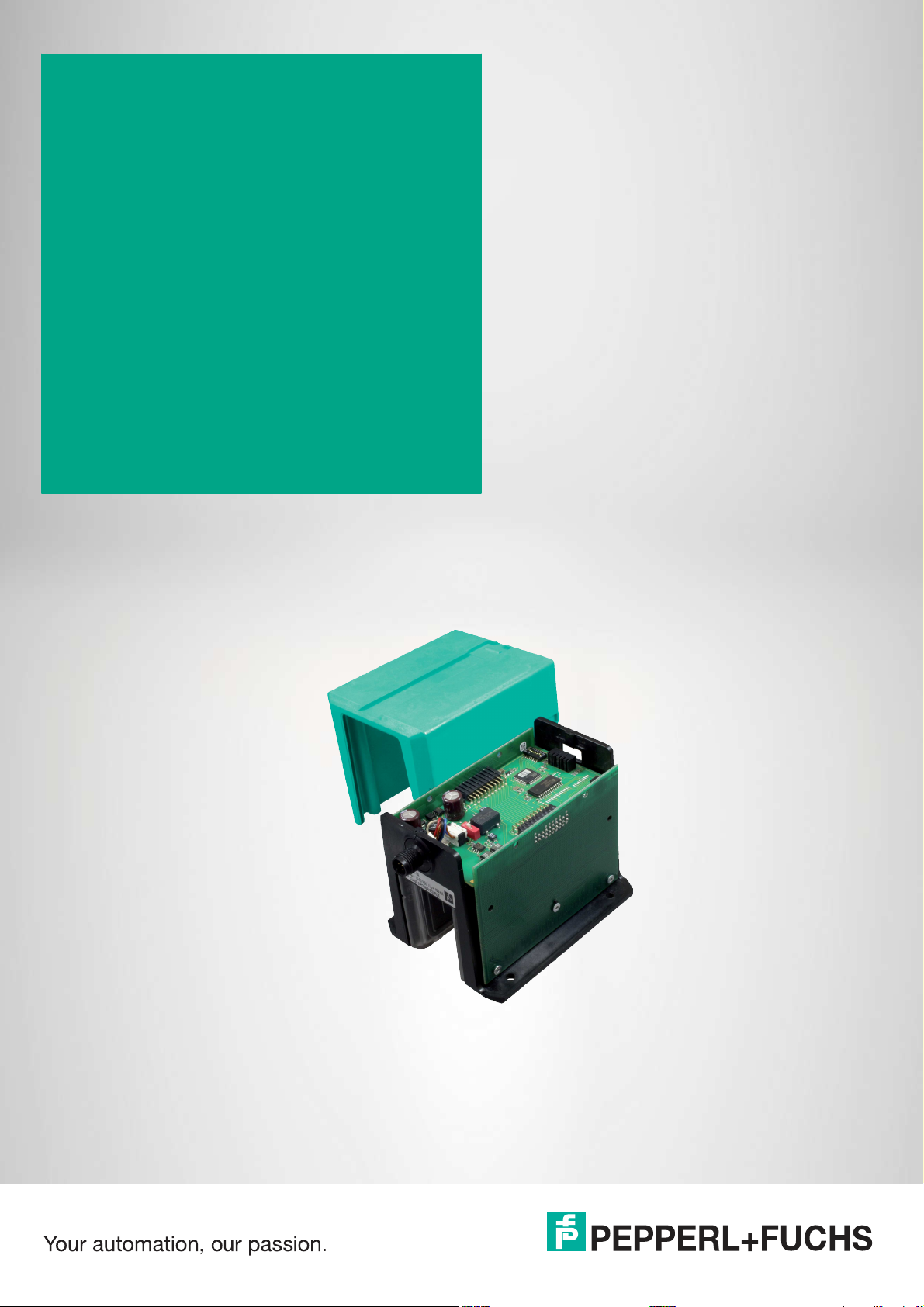
WCS* Read Head
Position Encoding System
Electrical Data
Manual
Page 2

With regard to the supply of products, the current issue of the following document is applicable: The
General Terms of Delivery for Products and Services of the Electrical Industry, published by the Central
Association of the Electrical Industry (Zentralverband Elektrotechnik und Elektroindustrie (ZVEI) e.V.)
in its most recent version as well as the supplementary clause: "Expanded reservation of proprietorship"
Worldwide
Pepperl+Fuchs Group
Lilienthalstr. 200
68307 Mannheim
Germany
Phone: +49 621 776 - 0
E-mail: [email protected]
North American Headquarters
Pepperl+Fuchs Inc.
1600 Enterprise Parkway
Twinsburg, Ohio 44087
USA
Phone: +1 330 425-3555
E-mail: [email protected]
Asia Headquarters
Pepperl+Fuchs Pte. Ltd.
P+F Building
18 Ayer Rajah Crescent
Singapore 139942
Phone: +65 6779-9091
E-mail: [email protected]
https://www.pepperl-fuchs.com
Page 3

WCS* Read Head Position Encoding System
Contents
1 Introduction................................................................................................................ 5
1.1 Content of this Document............................................................................. 5
1.2 Target Group, Personnel ............................................................................... 5
1.3 Symbols Used ................................................................................................ 6
2 Product Description ..................................................................................................7
2.1 Functional Description.................................................................................. 7
2.2 Areas of Use .................................................................................................10
3 Data Cables and Mounting/Dismounting the Read Head ....................................13
3.1 Data cable..................................................................................................... 13
3.2 Mounting/Dismounting the Read Head Enclosure................................... 14
4 RS-485 Interface (LS1xx*, LS2xx*)......................................................................... 16
4.1 Electrical Connection and Data Cables..................................................... 16
4.2 Hardware Configuration.............................................................................. 18
4.3 Data Protocols ............................................................................................. 21
4.4 Status and Error Messages ........................................................................ 27
4.5 LED Status Indication.................................................................................. 28
5 SSI Interface (LS3xx*) ............................................................................................. 30
5.1 Electrical Connection and Data Cables..................................................... 30
5.2 Hardware Configuration.............................................................................. 32
5.3 Data Protocols ............................................................................................. 34
5.4 Status and Error Messages ........................................................................ 36
5.5 LED Status Indication.................................................................................. 37
6 CANopen Interface (LS4xx*)................................................................................... 38
6.1 Electrical Connection .................................................................................. 38
6.2 Hardware Configuration.............................................................................. 39
6.3 Software Configuration ...............................................................................41
6.4 Data Protocols ............................................................................................. 41
6.5 LED Status Indication.................................................................................. 42
7 EtherNet/IP Interface (LS5xx*) ...............................................................................43
7.1 Electrical Connection .................................................................................. 43
7.2 Hardware Configuration.............................................................................. 45
2020-01
3
Page 4

WCS* Read Head Position Encoding System
Contents
7.3 Software Configuration ...............................................................................46
7.4 Data Protocols.............................................................................................. 49
7.5 LED Status Indication..................................................................................53
8 PROFINET Interface (LS6xx*) .................................................................................54
8.1 Electrical Connection ..................................................................................54
8.2 Hardware Configuration ..............................................................................45
8.3 Software Configuration ...............................................................................57
8.4 Data Protocols.............................................................................................. 59
8.5 LED Status Indication..................................................................................62
9 Options and Special Functions ..............................................................................63
9.1 Option D—Integrated Display in the Read Head, Type LS...D.................. 63
9.2 Option-E—Extended, Type WCS3B-LS2*E*, RS-485 .................................65
9.3 Option-H—Heating in Read Head, Type LS...H..........................................68
9.4 Option-S—Velocity Output, Type LS...S ..................................................... 69
10 Model Overview for WCS Read Heads................................................................... 70
11 Disposal ....................................................................................................................72
12 Appendix...................................................................................................................73
12.1 Cable Overview ............................................................................................73
2020-01
4
Page 5

WCS* Read Head Position Encoding System
Introduction
1 Introduction
1.1 Content of this Document
This document contains information required to use the product in the relevant phases of the
product life cycle. This may include information on the following:
• Product identification
• Delivery, transport, and storage
• Mounting and installation
• Commissioning and operation
• Maintenance and repair
• Troubleshooting
• Dismounting
• Disposal
Note
For full information on the product, refer to the further documentation on the Internet at
www.pepperl-fuchs.com.
The documentation comprises the following parts:
• This document
• Datasheet
In addition, the documentation may comprise the following parts, if applicable:
• EU-type examination certificate
• EU declaration of conformity
• Attestation of conformity
• Certificates
• Control drawings
• Instruction manual
• Other documents
1.2 Target Group, Personnel
Responsibility for planning, assembly, commissioning, operation, maintenance, and dismounting lies with the plant operator.
Only appropriately trained and qualified personnel may carry out mounting, installation, commissioning, operation, maintenance, and dismounting of the product. The personnel must have
read and understood the instruction manual and the further documentation.
Prior to using the product make yourself familiar with it. Read the document carefully.
2020-01
5
Page 6
WCS* Read Head Position Encoding System
Introduction
1.3 Symbols Used
This document contains symbols for the identification of warning messages and of informative
messages.
Warning Messages
You will find warning messages, whenever dangers may arise from your actions. It is mandatory
that you observe these warning messages for your personal safety and in order to avoid property damage.
Depending on the risk level, the warning messages are displayed in descending order as follows:
Danger!
This symbol indicates an imminent danger.
Non-observance will result in personal injury or death.
Warning!
This symbol indicates a possible fault or danger.
Non-observance may cause personal injury or serious property damage.
Caution!
This symbol indicates a possible fault.
Non-observance could interrupt the device and any connected systems and plants, or result in
their complete failure.
Informative Symbols
Note
This symbol brings important information to your attention.
Action
This symbol indicates a paragraph with instructions. You are prompted to perform an action or
a sequence of actions.
2020-01
6
Page 7
WCS* Read Head Position Encoding System
Product Description
2 Product Description
2.1 Functional Description
The WCS position encoding system consists of two main components:
Code Rail
The code rail carries information for the absolute code. The code rail is routed parallel to the
track for the material handling equipment and thus assigns a unique position to every point on
the track. It is possible to route the code rail at points only where positioning is required. The
system allows the code rail to be routed along curves and allows branches to be created. The
code rail is built to order and delivered in a bundle. Unless otherwise ordered, the code rail
always starts with position value 0 and ends with a maximum position according to the ordered
length in meters. The length of a code rail segment ranges from 0 to a maximum total length of
314.573 m (WCS3) or from 0 to a maximum total length of 327 m (WCS2).
Spacers can also be ordered for repair purposes or specific applications, stating the start or
end position of the desired section and the desired length in meters.
For identification applications ID-pads are available as short code rail sections, with a length of
between 250 mm and 264 mm and a unique identification number.
Read Head
The U-shaped read head scans the code rail photoelectronically without touching it. The read
head detects a new position value every 0.8 mm (WCS3) or 0.833 mm (WCS2).
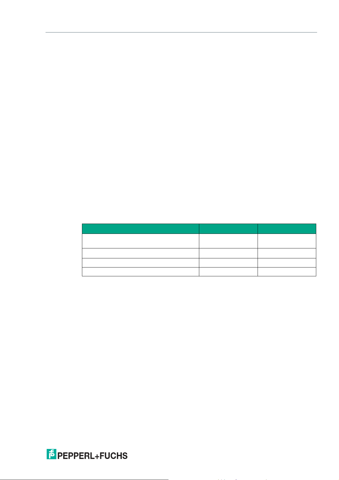
This results in the following data:
WCS2B WCS3B
Resolution ± 0.42 mm
1200 pos./m
Movement speed [v
Y axis (tolerance) ± 5 mm ± 15.5 mm
X axis (tolerance) ± 5 mm ± 14 mm
After insertion into the code rail, the read head determines a highly accurate position value
without reference or delay. The code rail can be scanned at very high speeds. The scanning
can be reproduced, is reliable, and is independent of temperature fluctuations.
The position value, movement speed, and error codes such as the contamination detection or
the "OUT" message can be transmitted directly from the read head to the control panel via a
communication interface. There are a number of types of interfaces available in the WCS3 read
head to achieve this, such as RS-485, SSI, CANopen, PROFINET, and EtherNet/IP.
There is a wide range of interface modules available for connecting to other interfaces:
• PROFINET
• PROFIBUS DP
] 12.5 m/s 12.5 m/s
max
± 0.40 mm
1250 pos./m
• EtherNet/IP
• EtherCAT
• DeviceNet
• CANopen
Each interface module can simultaneously accommodate up to four read heads with an RS485 interface and address each separately. This makes it easy to extend your plant at a later
stage.
In addition to automatic contamination detection, there are other optional extensions for the
2020-01
WCS read head. The options are indicated in the type code with the corresponding letter:
7
Page 8

WCS* Read Head Position Encoding System
Product Description
WCS2B and WCS3B
H Integrated heating element for an extended outside temperature range as
WCS3B
D Integrated display with a seven-segment display for position and diagnostic
E Read head with Extended option for long distances of up to 629.146
O Outdoor protective enclosure with degree of protection IP69 for outdoor
S Switching output for signaling when a limit speed is exceeded
The variants available can be found in the product selector at https://www.pepperl-fuchs.com,
as well as in the model overview for read heads, see chapter 10.
low as - 40 °C.
information.
meters.
use.
Mounting System
There are three different mounting systems available for mounting the code rail. The bracket
system, the WCS3 aluminum profile system, and the WCS2 aluminum profile system with fixture for a guide trolley. The three mounting systems can be screwed directly to the surface or
mounted on standard C profiles.
The bracket system is the easiest to mount as it features mounting brackets for straight section
elements and curved sections (vertical, horizontal). The brackets are screwed directly to the
code rail and to the surface and C profile.
As an alternative to the mounting brackets, the WCS3 aluminum profile system provides better
stabilization of the code rail and simplified mounting for long, straight sections. In this case, the
code rail is inserted into an extruded aluminum profile developed for the WCS and fixed in
place with a fixing cord. The aluminum profile rail is clipped to plastic brackets and attached to
the surface with a C profile.
The WCS2 aluminum profile rail system with guide trolley is intended for applications with high
running tolerances. The aluminum profile accommodates the code rail and the guide trolley.
The guide trolley is connected to the vehicle via a free-running tappet and guarantees that the
read head is always in the optimal position in relation to the code rail. At the same time, the
read head is decoupled from vehicle vibrations. Use of the guide trolley is generally recommended with the WCS2 read head due to the low read head gap. For the WCS3 read head with
outdoor protective enclosure, an optional guide trolley can be used in combination with the
WCS2 profile rail.
2020-01
8
Page 9

WCS* Read Head Position Encoding System
Product Description
Properties of the WCS
• Absolute position encoding system
• Photoelectric principle (infrared range)
• Proven and robust
• Easy to maintain
• No reference points required
• No calibration and adjustment work necessary
• Resistant to power failure
• Millimeter-precise positioning with absolute repeat accuracy
• Determination of position value in real time and regardless of temperature fluctuations
• Guaranteed reading up to a speed of 12.5 m/s
• High resolution = ±0.4 mm
• Variable route length:
• Up to 327 m (WCS2)
• Up to 314.573 m (WCS3)
• Up to 629.146 m (WCS Extended)
• The coding system is also suitable for curves with a radius of up to 0.5 m (does not apply
to systems with guide trolleys)
• A wide range of areas of application, e.g., automated storage and retrieval systems, mov-
ing carriages, monorail conveyors, galvanic plants, automatic and slewing cranes, elevators, as well as outdoors such as in harbors, offshore installations, and ships
• Various mounting systems available for installing the code rail
• Connection to any control panel possible, either directly or via interface module
• Connectivity to many fieldbus systems available
• Support during commissioning and maintenance due to extensive system diagnostics
options
• High functional reliability as a result of permanent self-diagnostics
• Contamination warning
• Optional heating for ambient temperatures down to -40 °C
• Digital output of an adjustable limit speed (optional)
• The WCS3-Outdoor has an IP69-compliant protective enclosure
2020-01
9
Page 10
WCS* Read Head Position Encoding System
Product Description
2.2 Areas of Use
The WCS can be used anywhere where material handling equipment has to be positioned precisely. The operating principle of the WCS enables it to be used in a diverse range of applications, including:
• Interruptions in the code rail
• Applications with curves and circular paths
• Use of multiple vehicles in a row
Due to the large tolerance between the read head and code rail, the WCS can be used for most
applications. In some cases, however, it is advantageous to use the WCS with a special protective enclosure or a guide trolley in conjunction with the aluminum profile system. Here are some
examples from the variety of application options:
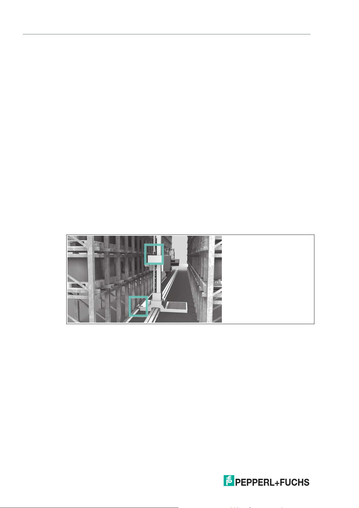
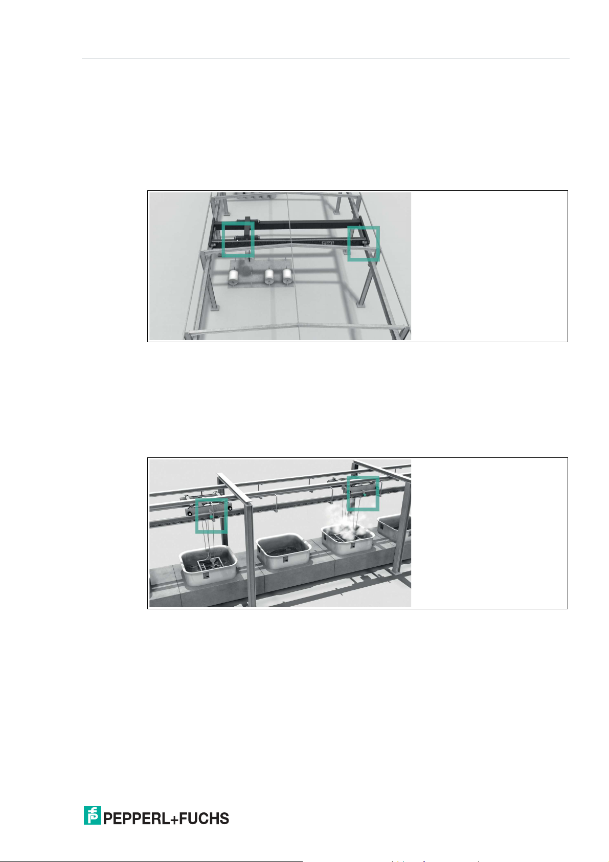
Automated Storage and Retrieval Systems (High-Bay Warehouses)
Moving carriages, lifting gear, and transversing carriages are each positioned with one read
head. The positioning is independent of the length of the code rail and always absolutely reproducible. For new high-bay warehouses we recommend the WCS3 system. For retrofits in older
warehouses, it may be beneficial to use the WCS2 in conjunction with the aluminum profile system:
• Easy to retrofit
• High mechanical tolerances between the measuring system and moving carriages possi-
ble
• Decoupling of vehicle vibrations
Figure 2.1 Automated storage and retrieval system (high-bay warehouse)
10
2020-01
Page 11
WCS* Read Head Position Encoding System
Product Description
Automatic Cranes
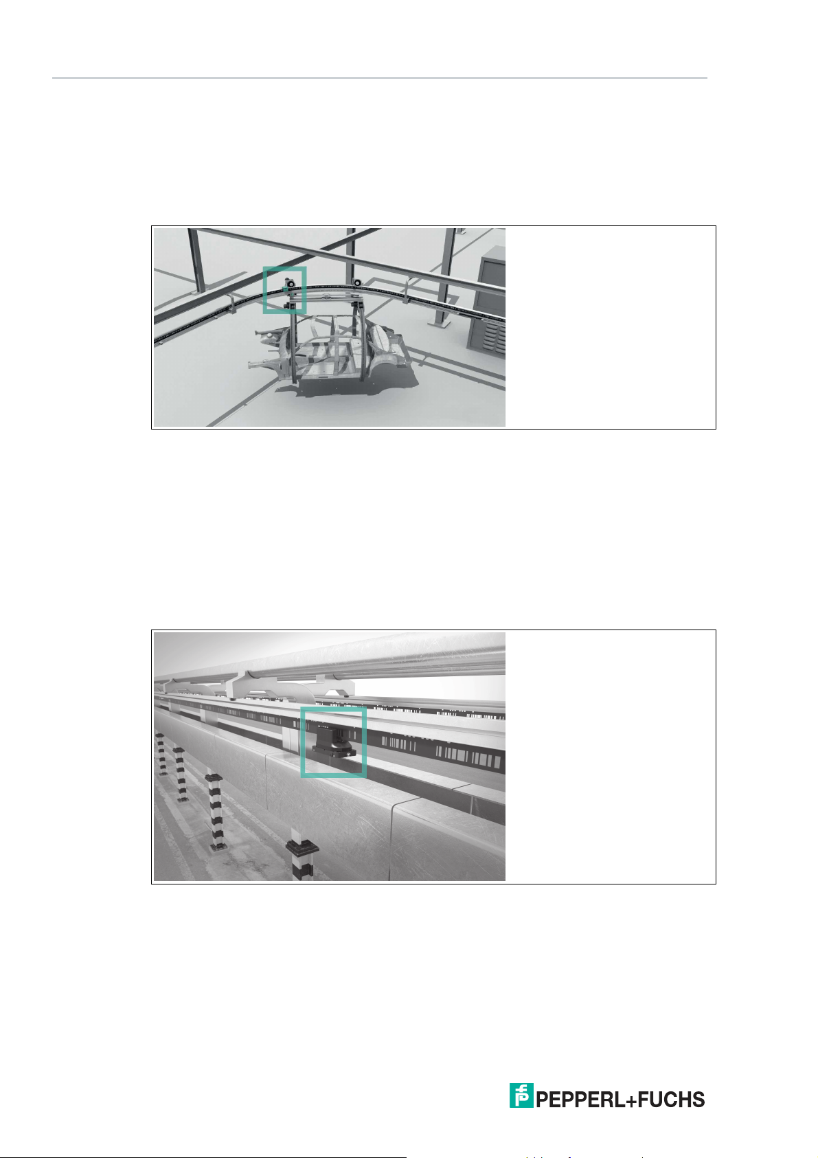
Automatic cranes are a typical application for the WCS2 in conjunction with the aluminum profile system. The crane is positioned using one read head each for the crane and the trolley
movement. At each point, the guide trolley ensures the optimal position of the read head in
relation to the code rail and decouples any vibrations from the crane track. Optional cleaning
brushes for the code rail can be attached to the guide trolley. This means that the WCS can be
used in a very dusty environment, such as in cement works or foundries. If the cranes are used
outdoors, the WCS3 is used with a special protective enclosure.
Figure 2.2 Automatic crane
Galvanic Plants
One or more vehicles in succession moving along a straight route. The vehicles automatically
bring the material to be galvanized into the corresponding bath. The high and adaptable light
output of the read heads has enabled the WCS position encoding system to perform extremely
well even under these difficult conditions. The WCS3 with protective enclosure is ideal for galvanic plants. In addition to degree of protection IP69, the enclosure is resistant to acids and
alkalis.
Figure 2.3 Galvanic plant
2020-01
11
Page 12
WCS* Read Head Position Encoding System
Product Description
Overhead Conveyors
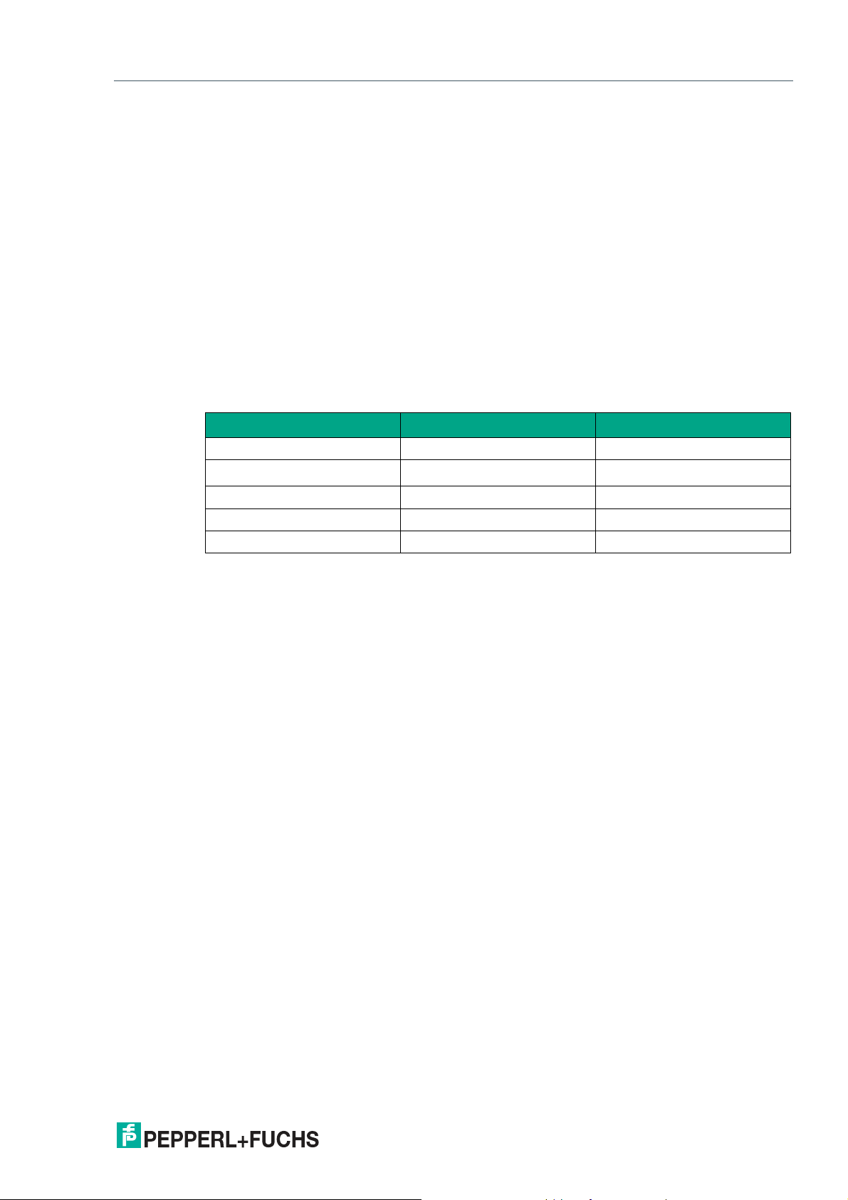
Many vehicles have to be positioned on a circular track—the WCS offers the optimal solution
for this. Branches (track switches) and curves can be created. The WCS3 is particularly wellsuited for this task. After a power failure, the current position of the vehicle is transferred to the
control panel immediately; the vehicle does not have to be moved. The WCS can also be used
for distances longer than 314.573 m.
Figure 2.4 Overhead conveyor
Harbor Applications
The WCS with protective enclosure is used for material handling plants in particularly demanding areas such as harbors, offshore installations, and ships. To meet the requirements of these
areas, the WCS includes an IP69-compliant protective enclosure that, in addition to protecting
against dust and humidity, has been specifically designed for resistance to aggressive substances such as salt water, salty air, acids, and alkalis. It offers increased impact resistance
compared to typical outdoor sources of interference such as falling branches and hailstorms. In
combination with built-in heating, the WCS can even be used in snow and temperatures as low
as -40 °C. The indicator LEDs and the display are always visible through the translucent enclosure material.
12
Figure 2.5 Power rail of a gantry crane
2020-01
Page 13
WCS* Read Head Position Encoding System
Data Cables and Mounting/Dismounting the Read Head
3 Data Cables and Mounting/Dismounting the Read Head
3.1 Data cable
A shielded data cable with twisted-pair wires is used for the electrical connection. Pepperl and
Fuchs can supply suitable preassembled M12 single-ended female cordsets (see chapter
12.1) or field-attachable M12 single-ended female cordsets and data cables.
Data cable WCS-DC*
There are 2 types of data cable available:
• WCS-DCS for stationary cable routing
• WCS-DCF for trailing cable and drag chain installations.
The data cables are twisted pairs and have a tinned copper braided shield. The braided shield
surrounds all wire pairs. The parameters of the data cables that are suitable for RS-485, SSI,
and CANopen data transfer are listed in the table below.
WCS-DCS WCS-DCF
Capacitance (core-core) 120 pF/m 60 pF/m
Cross section
Number of wires 6 (3 x 2) 6 (3 x 2)
External diameter 5.8 mm 7.5 mm
Temperature range -40 ... 80 °C -40 ... 70 °C
0.14 mm
2
0.25 mm
2
Cable routing
The basic prerequisite for uninterrupted data transfer is that the data cables are routed in such
a way that any coupling of electromagnetic fields and interference is excluded. For EMC-compliant cable routing, it is necessary to divide the cables into cable groups and route these
groups separately.
Group A
• Shielded data cable (including analog)
• Unshielded cable for DC and AC voltages 0 ... 60 V
• Shielded cable for DC and AC voltages 0 ... 230 V
• Coaxial cables for monitors
Group B
• Unshielded cable for DC and AC voltages 60 ... 400 V
Group C
• Unshielded cable for DC and AC voltages greater than 400 V
Shielding cables
The shielding of cables is required to suppress electromagnetic interference. Establishing a
low resistance or low impedance connection with the protective conductor is a particularly
important factor in ensuring that these interference currents do not become a source of interference themselves.
The WCSB2B and WCS3B read heads have no connection option for the cable shield. The
cable shield is connected to the plant potential in the switch cabinet with low resistance (large
area). In the case of high electromagnetic interference, it is advisable to connect the shield of
the data cable to the plant potential in the immediate vicinity of the read head with low resistance using a grounding clip.
2020-01
13
Page 14
WCS* Read Head Position Encoding System
1
Data Cables and Mounting/Dismounting the Read Head
3.2 Mounting/Dismounting the Read Head Enclosure
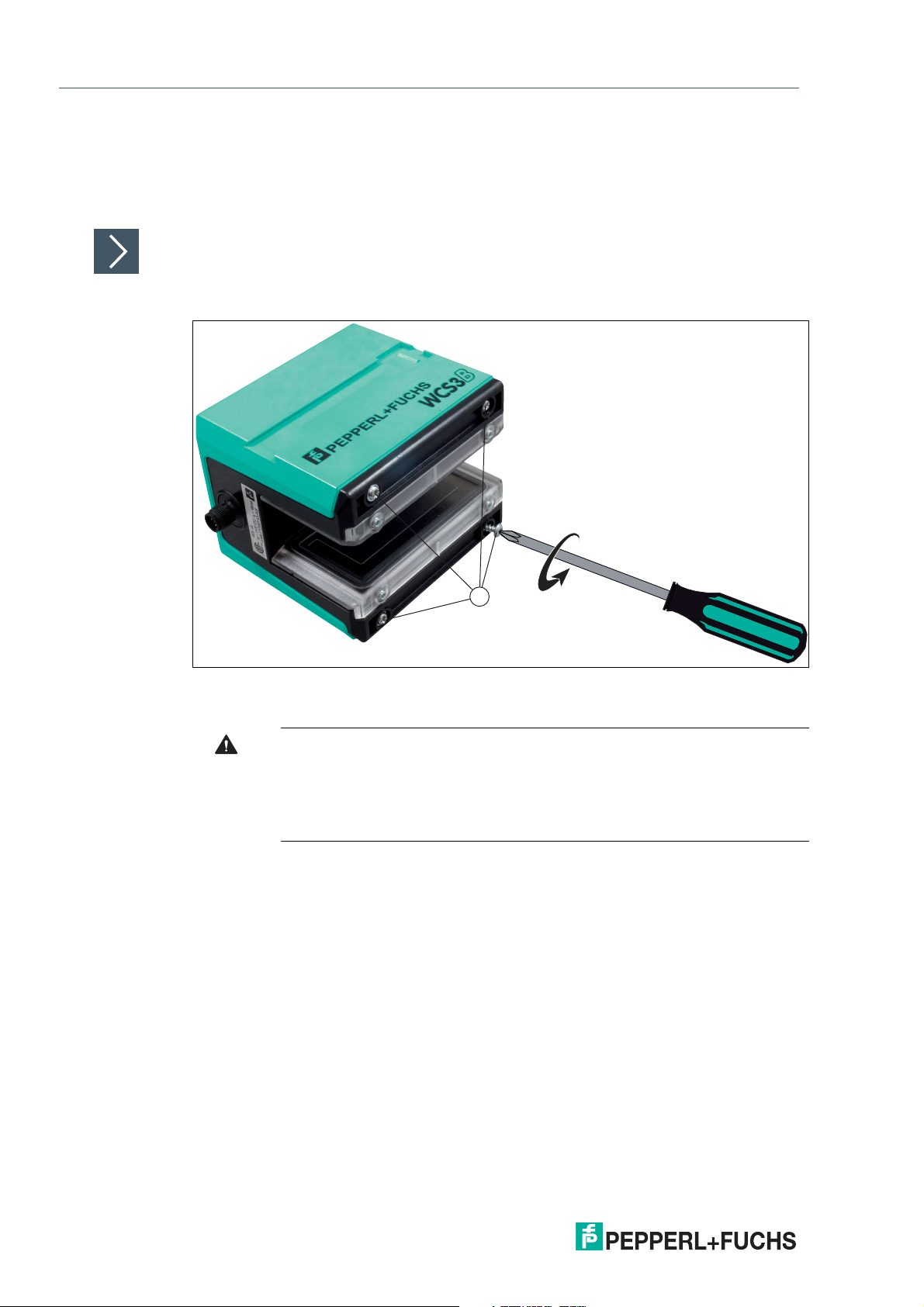
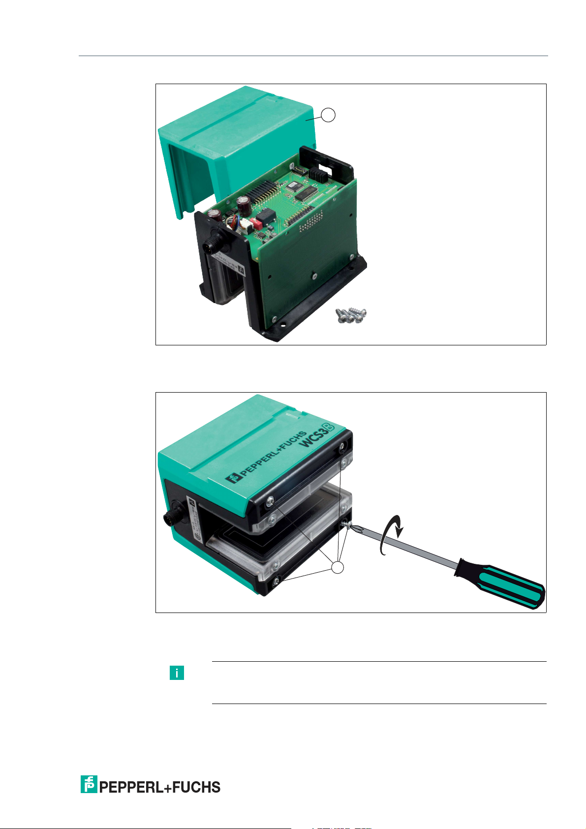
If required, the factory default setting of the read head can be changed using the respective
DIP switches. The DIP switches are located inside the housing on the PCB of the read head. To
access the DIP switches, open the enclosure cover of the read head. Proceed as follows:
Mounting/Dismounting
1.
Disconnect the device from the power supply.
Figure 3.1 Opening the read head
2.
Open the read head by removing the four screws (4) on the bottom of the read head.
Warning!
Property damage caused by electrostatic discharge (ESD)
If the housing is opened, the electronics may be damaged by electrostatic discharges.
• Use a wrist grounding strap or other ESD protective measures.
14
2020-01
Page 15
WCS* Read Head Position Encoding System
1
1
Data Cables and Mounting/Dismounting the Read Head
Figure 3.2 Removing the enclosure cover
3.
Remove the enclosure cover (1) from the read head. To do this, carefully pull the enclosure
cover upward.
Figure 3.3 Mounting the enclosure cover
4.
After making all adjustments, carefully slide the enclosure cover onto the read head and screw
it into place with the four screws.
Note
The settings of the DIP switches for the respective interfaces can be found in
the following chapters, under the menu item Hardware Configuration.
2020-01
15
Page 16
WCS* Read Head Position Encoding System
WCS2B-LS
UB 10 ... 30 V
GND
RS485+
2
4
1
3
RS485-
1
3
4
5
2
5 V
(intern)
S2
390Ω
220Ω
390Ω
WCS2B-LS2... S2 = ON
WCS2B-LS1... S2 = OFF
Velocity output *)
I
out
= max. 150 mA
*) only with Option S, velocity output
WCS3B-LS
UB 10 ... 30 V
GND
RS485+
1
2
4
3
5
RS485-
1
3
4
5
2
5 V
(intern)
S2
390Ω
220Ω
390Ω
WCS3B-LS2... S2 = ON
WCS3B-LS1... S2 = OFF
RS-485 Interface (LS1xx*, LS2xx*)
4 RS-485 Interface (LS1xx*, LS2xx*)
The serial interface of the read head allows the position values and other defined operating
data to be read out.
Up to four WCS2B and/or WCS3B read heads can be interconnected in one RS-485 bus line.
In this case, the read heads must have different addresses. The read head address must be
configured in the read head if it has not already been set. If the read head address is already
preset, this is indicated by the type designation of the read head. In the section "Type Overview
of WCS Read Head," you will find a detailed breakdown of the read head types, see chapter
10.
4.1 Electrical Connection and Data Cables
Caution!
Property damage and system malfunctions due to incorrect pinout
Incorrect assignment of the wire pairs to the respective pins can result in property damage and
system malfunctions.
• Note the assignment of the wire pairs to the pins as shown in the respective wiring dia-
grams.
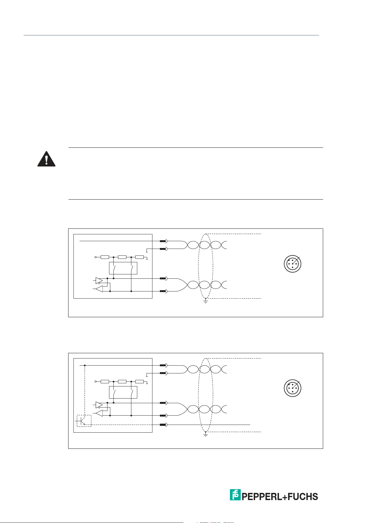
Connection diagram for WCS2B read head
The WCS2B read head is connected via a 5-pin M12 plug.
Figure 4.1 WCS2B, RS-485 interface
Connection diagram for WCS3B read head
The WCS3B read head is connected via a 5-pin M12 plug.
16
Figure 4.2 WCS3B, RS-485 interface
2020-01
Page 17
WCS* Read Head Position Encoding System
RS-485 Interface (LS1xx*, LS2xx*)
The counterpart of the plug connections, the 5-pin M12 socket, is not included in the scope of
delivery for the read head. You can obtain suitable connectors and cables from Pepperl+Fuchs,
see chapter 12.1.
Data cable
For the RS-485 data transfer path, a four-wire, shielded, twisted pair data cable must be used.
One wire pair is used for the supply voltage, and one pair for the RS-485 data connection. The
maximum length of the cable depends on the capacitance of the data cable—core-core—for
data transfer, and on the cross section of the cables for power supply to the read heads. For
data transfer, a small core cross section and thus a small cable capacitance is an advantage,
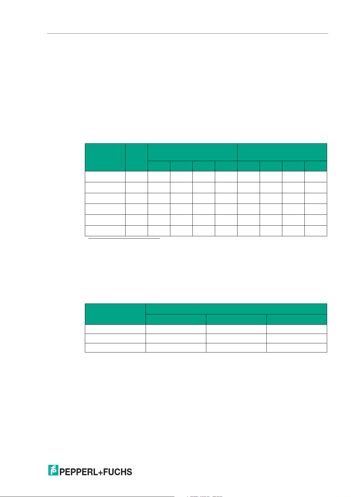
whereas for the power supply, the largest possible cross section is required. The table below
shows the possible cable lengths depending on the cable cross section.
Cable length
Number of read heads without
Cable cross
section AWG
2
0.14 mm
0.22 mm
0.25 mm
0.28 mm
0.34 mm
0.50 mm
~ 26 200 m 110 m 70 m 50 m 15 m 10 m 7 m 5 m
2
~ 24 320 m 170 m 110 m 80 m 30 m 15 m 10 m 7 m
2
- 350 m 190 m 130 m 90 m 35 m 17 m 12 m 8 m
2
- 400 m 220 m 150 m 110 m 40 m 20 m 15 m 10 m
2
~ 22 500 m 250 m 180 m 140 m 50 m 25 m 17 m 12 m
2
~ 20 500 m 400 m 270 m 200 m 70 m 35 m 25 m 17 m
heater
1
1 2 3 4 1 2 3 4
Number of read heads with
heater
1. American Wire Gauge, a system commonly used in North America for the specification of wire diameters in electrical
engineering.
In the calculations, the worst-case scenario was assumed: All read heads are located at the
end of the data line. In the case of large cable lengths, and when connecting multiple WCS2
read heads with a heater, 6-wire data cables (3 x 2) can be used. These data cables use two
pairs for the power supply (doubling the cable cross section), and one pair for the RS-485 data
line. The table below shows the possible cable lengths depending on the cable capacitance
(core-core). The number of connected read heads is of no significance.
Capacitance
(core-core)
RS-485 interface
19.2 kb 62.5 kb 187.5 kb
60 pF 500 m 500 m 300 m
90 pF 500 m 450 m 275 m
120 pF 500 m 400 m 250 m
2020-01
17
Page 18
WCS* Read Head Position Encoding System
1
3
2
RS-485 Interface (LS1xx*, LS2xx*)
4.2 Hardware Configuration
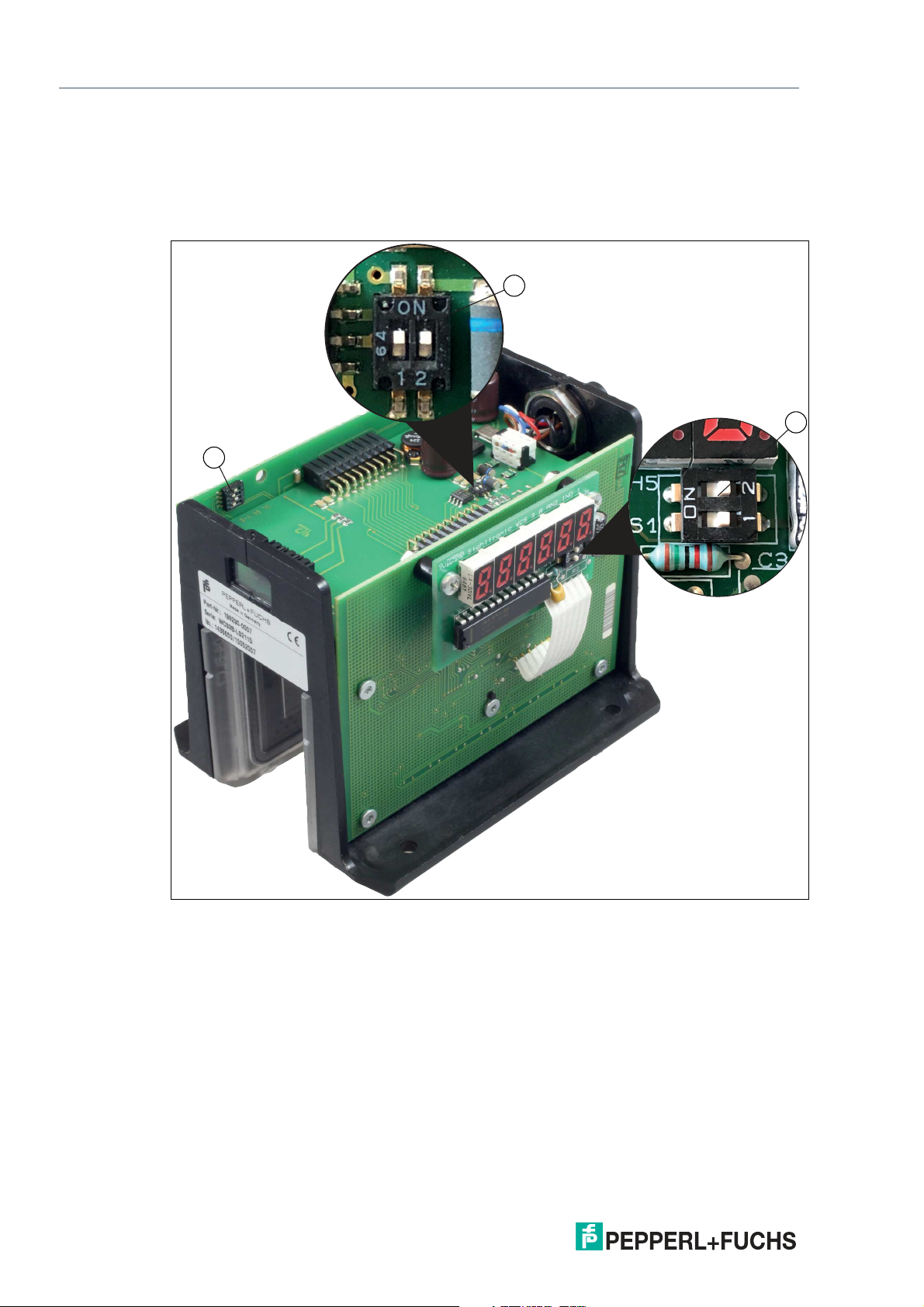
You can change the hardware and software configuration of the read head in the read head.
The changes to the read head type are made with two DIP switches or with three if you have a
read head with the "Display" option: S1 (1) is a DIP switch with four switch positions, S2 (2) and
S1D (3) are switches with two switch positions each.
Figure 4.3 Positions of the DIP switches
1. Configuration switch S1, 4-way (address, baud rate)
2. Configuration switch S2, 2-way (terminator)
3. Configuration switch S1D, 2-way (display)
18
2020-01
Page 19

WCS* Read Head Position Encoding System
RS-485 Interface (LS1xx*, LS2xx*)
Changing the read head address
Configuration switch "S1"
Read head type
WCS2B-LS***-0
WCS3B-LS***-0
WCS2B-LS***-1
WCS3B-LS***-1
WCS2B-LS***-2
WCS3B-LS***-2
WCS2B-LS***-3
WCS3B-LS***-3
WCS3B-LS***S-0 OFF X X X 0
WCS3B-LS***S-1 ON X X X 1
OFF OFF X X 0
ON OFF X X 1
OFF ON X X 2
ON ON X X 3
Address1 2 3 4
Changing the terminator
WCS2B and WCS3B
Configuration switch "S2"
Terminator
ON ON ON
OFF OFF OFF
1 2
Changing the baud rate
Base types LS*11/LS*21:
Read head type
(* = 1 or 2)
WCS2B-LS*11
WCS3B-LS*11
WCS2B-LS*21
WCS3B-LS*21
Base types LS231/LS261
Read head type
(* = 1 or 2)
WCS2B-LS*61
WCS3B-LS*61
WCS2B-LS*31
WCS3B-LS*31
Configuration switch "S1"
Baud rate1 2 3 4
X X OFF X 187.5 kBaud
X X ON X 62.5 kBaud
Configuration switch "S1"
Baud rate1 2 3 4
X X OFF X 38.4 kBaud
X X ON X 31.25 kBaud
2020-01
19
Page 20
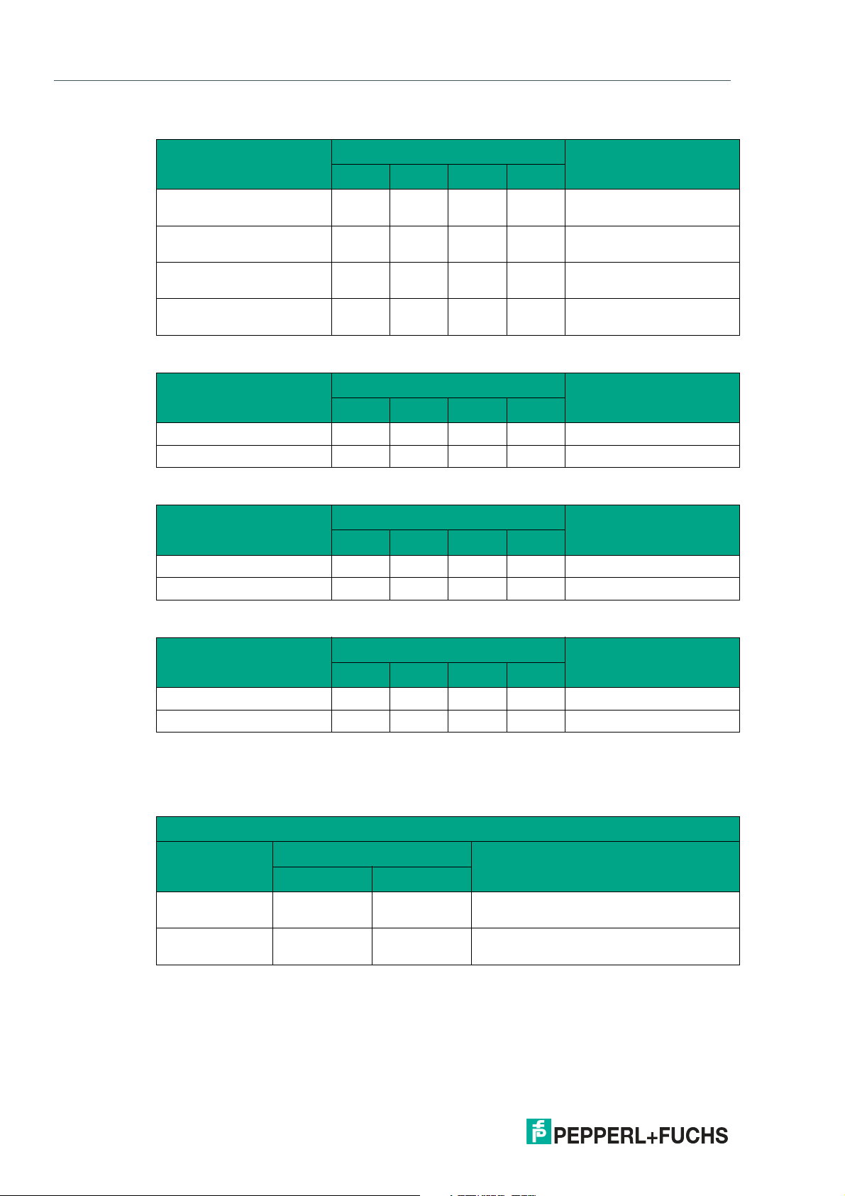
WCS* Read Head Position Encoding System
RS-485 Interface (LS1xx*, LS2xx*)
Base types LS246/LS256
Read head type
(* = 1 or 2)
WCS2B-LS*46
WCS3B-LS*46
WCS2B-LS*47
WCS3B-LS*47
WCS2B-LS*56
WCS3B-LS*56
WCS2B-LS*57
WCS3B-LS*57
Base types LS*1xS/LS*2xS
Read head type
(* = 1 or 2, x = 1, 6, or 7)
WCS3B-LS*1xS X OFF X X 187.5 kBaud
WCS3B-LS*2xS X ON X X 62.5 kBaud
Configuration switch "S1"
X X OFF OFF 19.2 kBaud even parity
X X OFF ON 19.2 kBaud no parity
X X ON OFF 9.6 kBaud even parity
X X ON ON 9.6 kBaud no parity
Configuration switch "S1"
Baud rate1 2 3 4
Baud rate1 2 3 4
Base types LS*3xS/LS*6xS
Read head type
(* = 1 or 2, x = 1, 6, or 7)
WCS3B-LS*6xS X OFF X X 38.4 kBaud
WCS3B-LS*3xS X ON X X 31.25 kBaud
Base types LS*3xS/LS*6xS
Read head type
(* = 1 or 2, x = 1, 6, or 7)
WCS3B-LS*4xS X OFF X X 19.2 kBaud
WCS3B-LS*5xS X OFF X X 9.6 kBaud
Configuration switch "S1"
Baud rate1 2 3 4
Configuration switch "S1"
Baud rate1 2 3 4
Adjusting the Display
You can rotate the character position on the display 180° using the S1D DIP switch. This allows
you to read the displayed values easily regardless of the installation position of the read head.
WCS3B
Configuration switch "S1D"
Display position
0° OFF OFF The displayed value can be read on a
180° ON ON The displayed value can be read on a
Comment1 2
code rail mounted upright.
code rail mounted suspended.
20
2020-01
Page 21
WCS* Read Head Position Encoding System
Start
2
0
2
1
2
6
2
5
2
2
2
3
2
4
2
7
Stop
LSB MSB
Bit 0 1 2 3 4 5 6 7 8
RS-485 Interface (LS1xx*, LS2xx*)
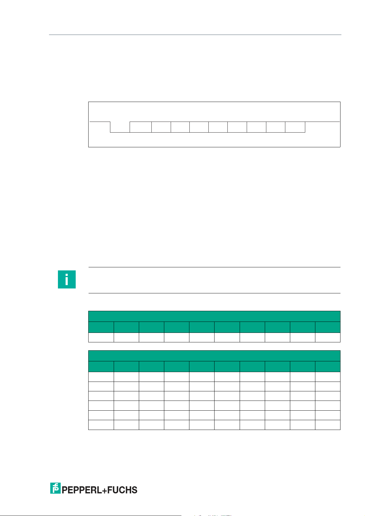
4.3 Data Protocols
Various data protocols and data transmission speeds are available for direct connection of the
read head to the higher-level control panel via a serial communication channel. The data protocols and baud rates are identical for the respective types in the WCS2B and WCS3B read
heads.
A byte has the following format:
Figure 4.4 Data structure
For data protocols 1 and 2, the eighth data bit is used to distinguish between request bytes and
response bytes. For control panels that do not support direction control via the eighth data bit,
data protocol 3 is available. Read heads with RS-485 interface and data protocol 3 can be supplied as type:
LSxx6 = data protocol 3 with parity (even parity), 9 bits/byte
LSxx7 = data protocol 3 without parity = 8 bits/byte.
Response time
The minimum response time of the read head (start sending the first data bytes from the
response telegram) depends on the internal time sequence of the read head and is 10 ... 180
sec for data protocol 1 and 2.
For data protocol 3, the response time is a byte time + 10 ... 100 sec. The byte time depends
on the baud rate and is calculated from 1/baud rate * 11,000 in sec.
Example: 38.4 kBaud
Byte time = 1/38.4 * 11,000 = 286.5 sec.
Note
Note the different data protocols for extended read head, see chapter 9.2.
Data protocol 1
Request byte for read head
Byte Bit 8 Bit 7 Bit 6 Bit 5 Bit 4 Bit 3 Bit 2 Bit 1 Bit 0
1 0 0 0 F0 0 0 A1 A0
Response telegram from the read head
Byte Bit 8 Bit 7 Bit 6 Bit 5 Bit 4 Bit 3 Bit 2 Bit 1 Bit 0
Byte 1 0
Byte 2 0
Byte 3 0
Byte 4 0
Byte 5 0
Byte 6 0
OUT ERR A1 A0 DB P18 P17 P16
P15 P14 P13 P12 P11 P10 P09 P08
P07 P06 P05 P04 P03 P02 P01 P00
OUT ERR A1 A0 DB P18 P17 P16
P15 P14 P13 P12 P11 P10 P09 P08
P07 P06 P05 P04 P03 P02 P01 P00
2020-01
21
Page 22
WCS* Read Head Position Encoding System
RS-485 Interface (LS1xx*, LS2xx*)
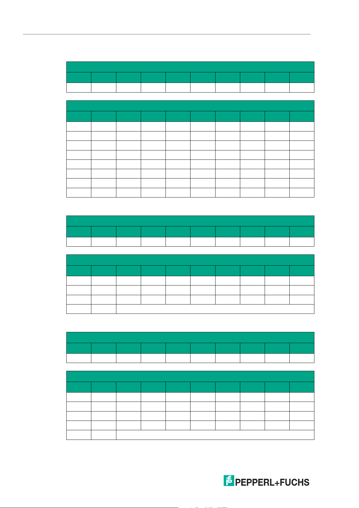
Data protocol 1 with position and velocity output
Request byte for read head
Byte Bit 8 Bit 7 Bit 6 Bit 5 Bit 4 Bit 3 Bit 2 Bit 1 Bit 0
1 1 0 0 0 0 0 A1 A0
Response telegram from the read head
Byte Bit 8 Bit 7 Bit 6 Bit 5 Bit 4 Bit 3 Bit 2 Bit 1 Bit 0
Byte 1 0
Byte 2 0
Byte 3 0
Byte 4 0
Byte 5 0
Byte 6 0
Byte 7 0
Byte 8 0
OUT ERR A1 A0 DB P18 P17 P16
P15 P14 P13 P12 P11 P10 P09 P08
P07 P06 P05 P04 P03 P02 P01 P00
SST SP6 SP5 SP4 SP3 SP2 SP1 SP0
OUT ERR A1 A0 DB P18 P17 P16
P15 P14 P13 P12 P11 P10 P09 P08
P07 P06 P05 P04 P03 P02 P01 P00
SST SP6 SP5 SP4 SP3 SP2 SP1 SP0
Data protocol 2
Request byte for read head
Byte Bit 8 Bit 7 Bit 6 Bit 5 Bit 4 Bit 3 Bit 2 Bit 1 Bit 0
1 0 1 1 F0 0 0 A1 A0
Response telegram from the read head
Byte Bit 8 Bit 7 Bit 6 Bit 5 Bit 4 Bit 3 Bit 2 Bit 1 Bit 0
Byte 1 0
Byte 2 0
Byte 3 0
Byte 4 0
OUT ERR A1 A0 DB P18 P17 P16
P15 P14 P13 P12 P11 P10 P09 P08
P07 P06 P05 P04 P03 P02 P01 P00
Exclusive or link, byte 1 ... Byte 3
Data protocol 2 with position and velocity output
Request byte for read head
Byte Bit 8 Bit 7 Bit 6 Bit 5 Bit 4 Bit 3 Bit 2 Bit 1 Bit 0
1 1 1 1 0 0 0 A1 A0
Response telegram from the read head
22
Byte Bit 8 Bit 7 Bit 6 Bit 5 Bit 4 Bit 3 Bit 2 Bit 1 Bit 0
Byte 1 0
Byte 2 0
Byte 3 0
Byte 4 0
Byte 5 0
OUT ERR A1 A0 DB P18 P17 P16
P15 P14 P13 P12 P11 P10 P09 P08
P07 P06 P05 P04 P03 P02 P01 P00
SST SP6 SP5 SP4 SP3 SP2 SP1 SP0
Exclusive or link, byte 1 ... Byte 4
2020-01
Page 23
WCS* Read Head Position Encoding System
RS-485 Interface (LS1xx*, LS2xx*)
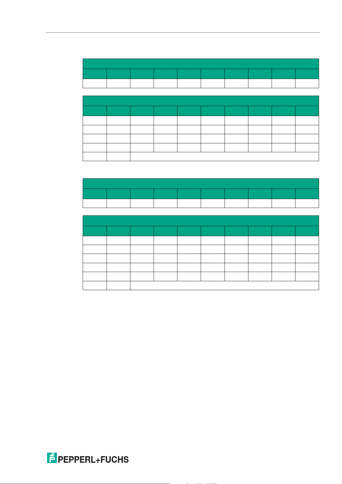
Data protocol 3
Request byte for read head
Byte Bit 8 Bit 7 Bit 6 Bit 5 Bit 4 Bit 3 Bit 2 Bit 1 Bit 0
PAR 1 0 0 F0 0 0 A1 A0
Response telegram from the read head
Byte Bit 8 Bit 7 Bit 6 Bit 5 Bit 4 Bit 3 Bit 2 Bit 1 Bit 0
Byte 1 PAR
Byte 2 PAR
Byte 3 PAR
Byte 4 PAR
0 0 A1 A0 0 DB OUT ERR
0 0 0 P18 P17 P16 P15 P14
0 P13 P12 P11 P10 P09 P08 P07
0 P06 P05 P04 P03 P02 P01 P00
Byte 5 PAR
Data protocol 3 with position and velocity output
Exclusive or link, byte 1 ... Byte 4
Request byte for read head
Byte Bit 8 Bit 7 Bit 6 Bit 5 Bit 4 Bit 3 Bit 2 Bit 1 Bit 0
PAR 1 1 1 0 0 0 A1 A0
Response telegram from the read head
Byte Bit 8 Bit 7 Bit 6 Bit 5 Bit 4 Bit 3 Bit 2 Bit 1 Bit 0
Byte 1 PAR
Byte 2 PAR
Byte 3 PAR
Byte 4 PAR
Byte 5 PAR
Byte 6 PAR
0 SST A1 A0 0 DB OUT ERR
0 0 0 P18 P17 P16 P15 P14
0 P13 P12 P11 P10 P09 P08 P07
0 P06 P05 P04 P03 P02 P01 P00
0 SP6 SP5 SP4 SP3 SP2 SP1 SP0
Exclusive or link, byte 1 ... Byte 5
2020-01
23
Page 24
WCS* Read Head Position Encoding System
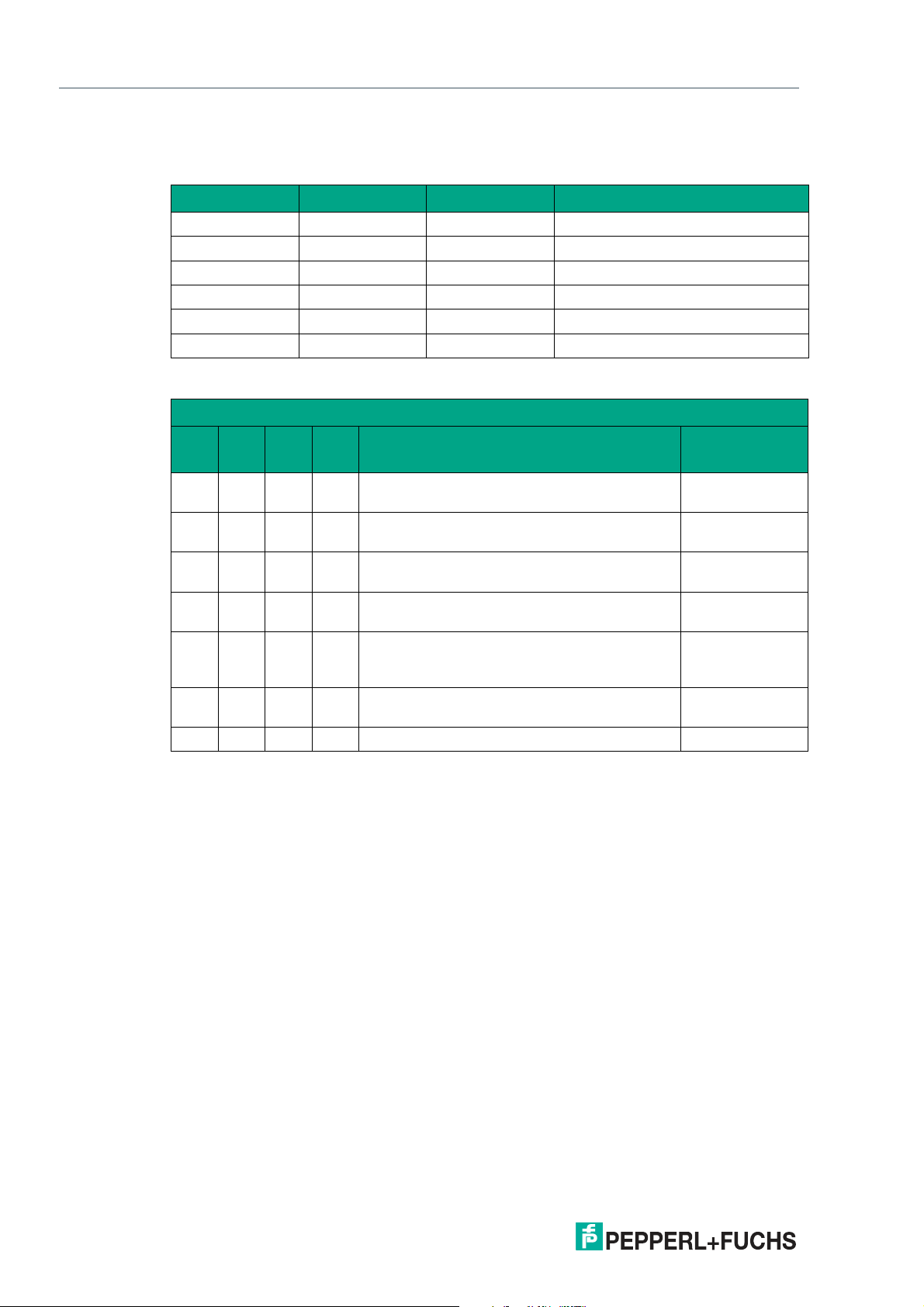
RS-485 Interface (LS1xx*, LS2xx*)
Description of the protocol data
Activation of the read head
F0 A1 A0 Read head address
x 0 0 Read head address 0
x 0 1 Read head address 1
x 1 0 Read head address 2
x 1 1 Read head address 3
0 x x Send position value
1 x x Send diagnosis result
Data from read head
Function number for read head F0=0 (send position value)
ERR DB OUT SST Description
0 0 0 x Current position value in P00 ... P18, binary
coded
0 0 1 x Read head outside the code rail, no position
value (see OUT message)
0 1 0 x Current position value in P00 ... P18, binary
coded
0 1 1 x No position value, read head outside the code
rail (see OUT message)
1 x x x No position value, error message from read
head, error number in P00 ... P04, binary
coded
x x x 1 Current speed unknown, last speed in
SP0 ... SP6 *)
x x x 0 Current speed in SP0 ... SP6 *) -
State of the read
head lens
Good
Good
Poor
Poor
-
-
*) Speed information
The speed is binary coded in bits SP0 to SP6.
SP0...SP6... Speed in 0.1 m/s, binary coded
0: Speed less than 0.1 m/s
126: Speed more than 12.5 m/s
127: Speed unknown
Example:
SP0...SP6... 1: Speed 0.1 m/s
37: Speed 3.7 m/s
112: Speed 11.2 m/s
Diagnostic function F0=1
The read head can be requested to perform a diagnosis of the photoelectrics via the request
byte to the read head. For this purpose, the read head must be located outside of the code rail.
On the WCS2B and WCS3B read heads, the degree of dirt accumulation on the photoelectrics
is monitored automatically during operation and the diagnostic bit (DB) set if dirt accumulation
is too high. Thus the request for diagnosis to the read head via F0 in the request byte is no longer necessary. However, for reasons of downward compatibility, this function is also supported
by the new read heads.
2020-01
24
Page 25
WCS* Read Head Position Encoding System
RS-485 Interface (LS1xx*, LS2xx*)
Diagnostic bit (DB)
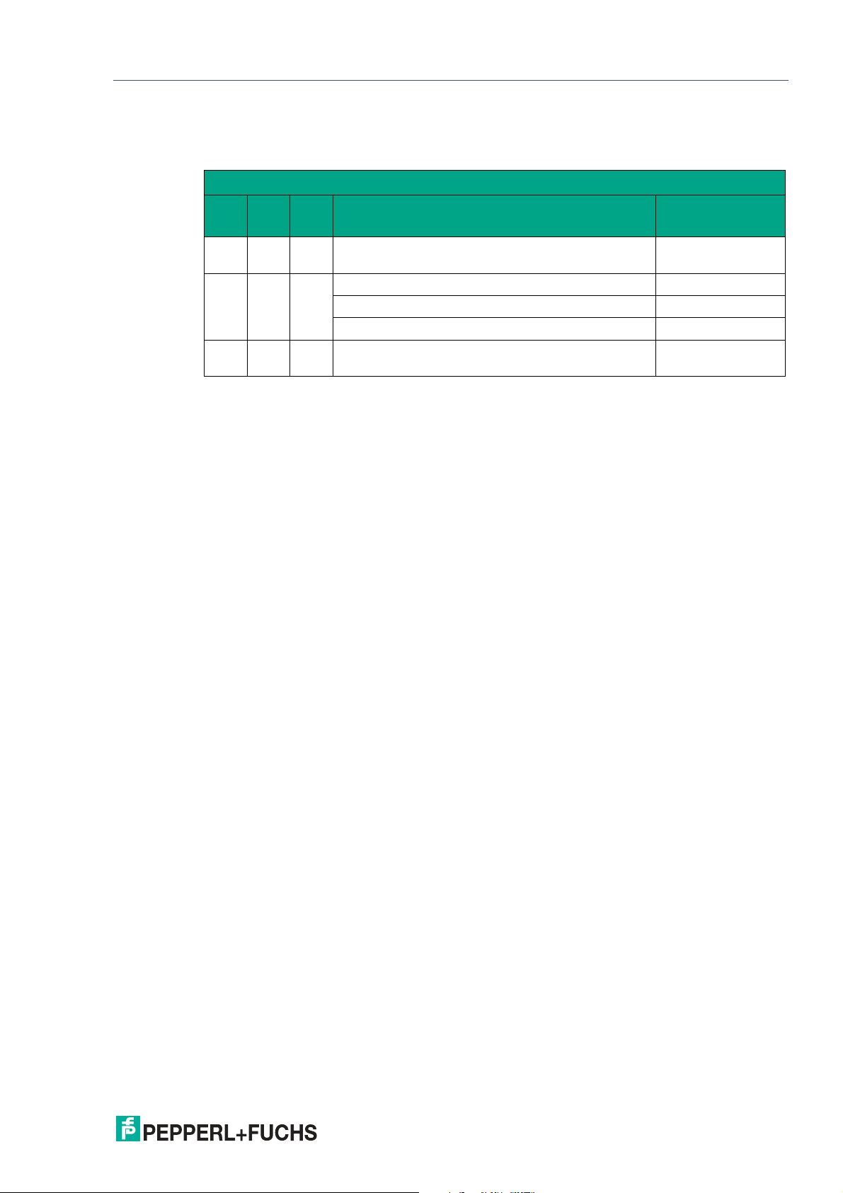
Diagnostic bit DB displays the result of the integrated diagnostics of the read head.
Function number for read head F0 = 1 (send diagnosis result)
ERR DB OUT Description
0 1 0 Diagnosis invalid, read head not outside of the
code rail
0 1 1 Diagnosis result in P16 ... P18 -
P16 ... P18 = 0 Good
P16 ... P18 > 0 Poor
1 x x Error message from read head, error message in
P00 ... P04, binary coded
Contamination detection
Read heads WCS2B and WCS3B continually monitor the condition of the lenses. If a drop in
light output is detected on the infrared transmitter, e.g., as a result of contamination of the clear
protective lenses, the read head automatically increases the light intensity. If the level of contamination is too high, a warning message is sent to the higher-level control panel (diagnostic
bit DB=1). The automatic light adjustment in the read head allows you sufficient time to clean
the read head as part of the next servicing procedure. The WCS3B read head emits a visual
signal for the "contamination detected" state: the yellow and red LEDs on the front of the read
head flash alternately. To clean the lenses, the read head must be removed from the code rail
(removed from the mounting base). After cleaning the transparent protective lenses, the contamination message is automatically deleted from the read head. If the message is not reset
despite careful cleaning or replacement of the plastic protective lenses, there may be an error.
In this case, the read head must be sent for inspection.
State of the read
head lens
-
-
2020-01
25
Page 26
WCS* Read Head Position Encoding System
RS-485 Interface (LS1xx*, LS2xx*)
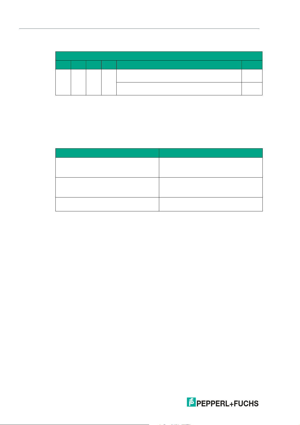
OUT message
Function number for read head F0 = 0 (send position value)
ERR DB OUT SST Description State
0 x 1 x P00...P18 = 0 -> read head is partially outside the code
rail
P00 = 1, P02...P18 = 0 -> read head is completely
outside the code rail
OUT means that the position value cannot be determined because the position of the code rail
in the read head gap is incorrect.
OUT A (A=All) means that there is no code rail in the read head gap; all light barriers of the
read head report a signal.
The "OUT" message may be desirable and correct, e.g., if the code rail is interrupted and the
read head sends this information between the individual rail pieces to the control panel. If the
"OUT" message must not occur, the following test steps must be performed:
Result of the check Remedy
The upper edge of the code rail is outside the
tolerance range of the read head
The plastic protective lenses on the optical
unit are dirty or scratched
Incidence of extraneous light • Protect the read head against any inci-
OUT
OUT A
• Align the code rail precisely
• Align the read head
• Use the guide system for the read head
• Clean optical unit
• Ensure the read head is cleaned
• Change the protective lenses
dence of extraneous light
If these measures do not solve the problem, the read head must be sent for inspection.
26
2020-01
Page 27
WCS* Read Head Position Encoding System
RS-485 Interface (LS1xx*, LS2xx*)
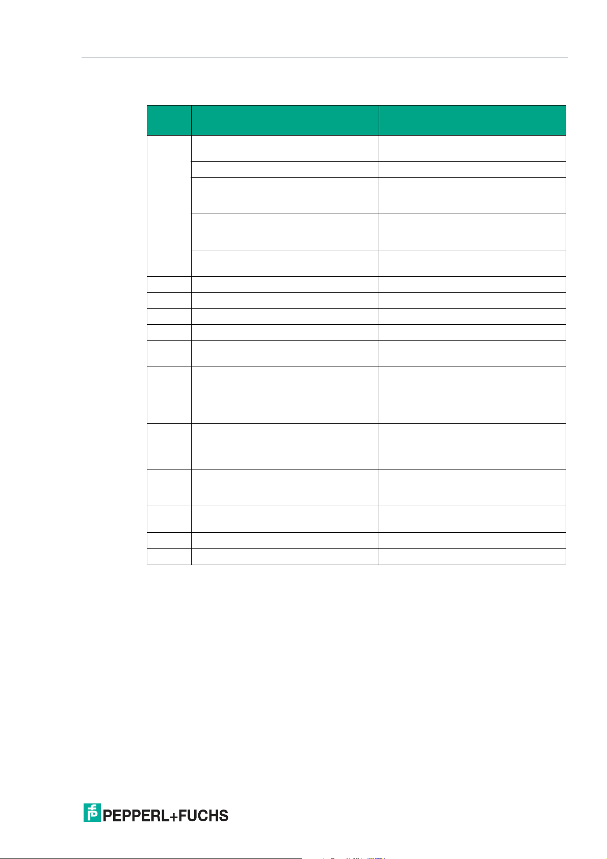
4.4 Status and Error Messages
Error
number Cause Remedy
1
2
3 RAM error, WCS read head Send WCS read head for repair
4 EPROM error, WCS read head Send WCS read head for repair
5 ROM error, WCS read head Send WCS read head for repair
6 Reserved
7 No position value available Message only after switching on the
8
9
10
11
12
13 WCS read head cannot be addressed by
14 Read head is located in the initialize or
15 Interface module is not set for communi-
19 RAM error in interface module Send interface module for repair
20 EPROM error in interface module Send interface module for repair
WCS read head cannot calculate position value because:
Optical unit is dirty Clean optical unit
Plastic protective lenses are scratched Align WCS read head and code rail cor-
Position of the read head in relation to the
code rail is incorrect
Light barriers have failed Check light barriers; if necessary send
Data transfer error between WCS read
head and interface module, data transfer
disrupted
the interface module
diagnostic routine
cation with multiple WCS read heads
rectly; replace scratched plastic protective lenses
Check the position of the WCS read head
in relation to the code rail; install WCS
read head correctly
for repair
WCS read head and/or after a RESET
Check the cable connection from the
WCS read head to the interface module;
check the shielding, protective earth,
cable routing (EMC)
Check the cable connection from the
WCS read head to the interface module;
check the operating voltage of the read
head
Wait for initialization; exit diagnostics (set
the selector switch on the interface module to 0 ... 7)
Send interface module for correct configuration setting
2020-01
27
Page 28
WCS* Read Head Position Encoding System
1 2 3
RS-485 Interface (LS1xx*, LS2xx*)
4.5 LED Status Indication
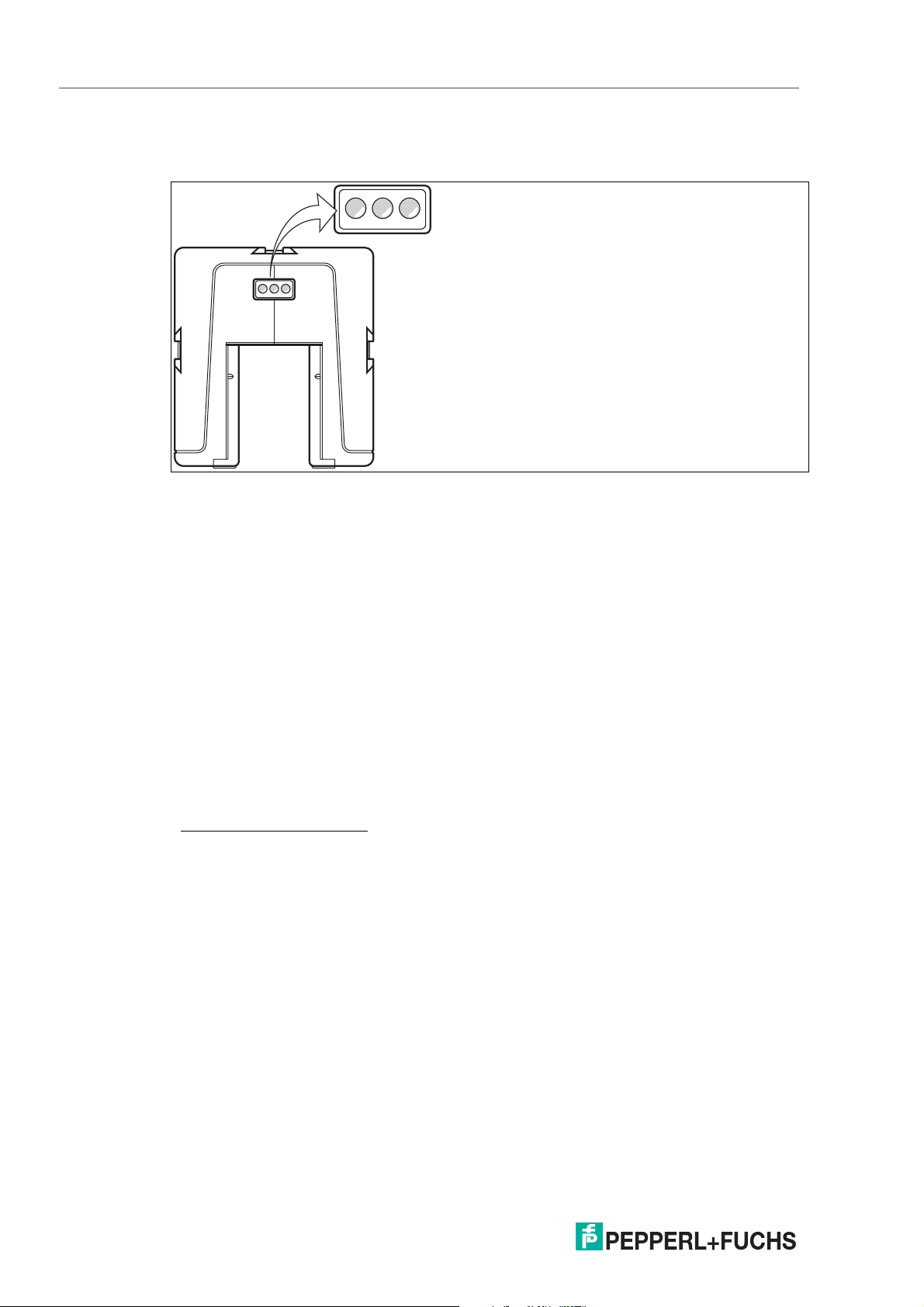
WCS3B-LS1xx*/ WCS3B-LS2xx*
1 Green LED
2 Yellow LED
3 Red LED
Display Meaning
Operating indicator Green LED: Power on
Data flow indicator
Velocity display
2
1
Yellow LED: Data transfer active
Yellow LED
Off if limit speed exceeded
Fault indicator Red LED
Flashing: Read head outside the code rail
Permanently lit: Internal diagnostic error
Contamination indicator Yellow LED and red LED flashing alternately: Read
head lens dirty (f=1.5 Hz)
Function indicator Yellow LED and red LED light up for 2 seconds after
power on or reset
1. Only for read heads with no velocity output
2. Only for read heads with velocity output
28
2020-01
Page 29
WCS* Read Head Position Encoding System
1 2 3
RS-485 Interface (LS1xx*, LS2xx*)
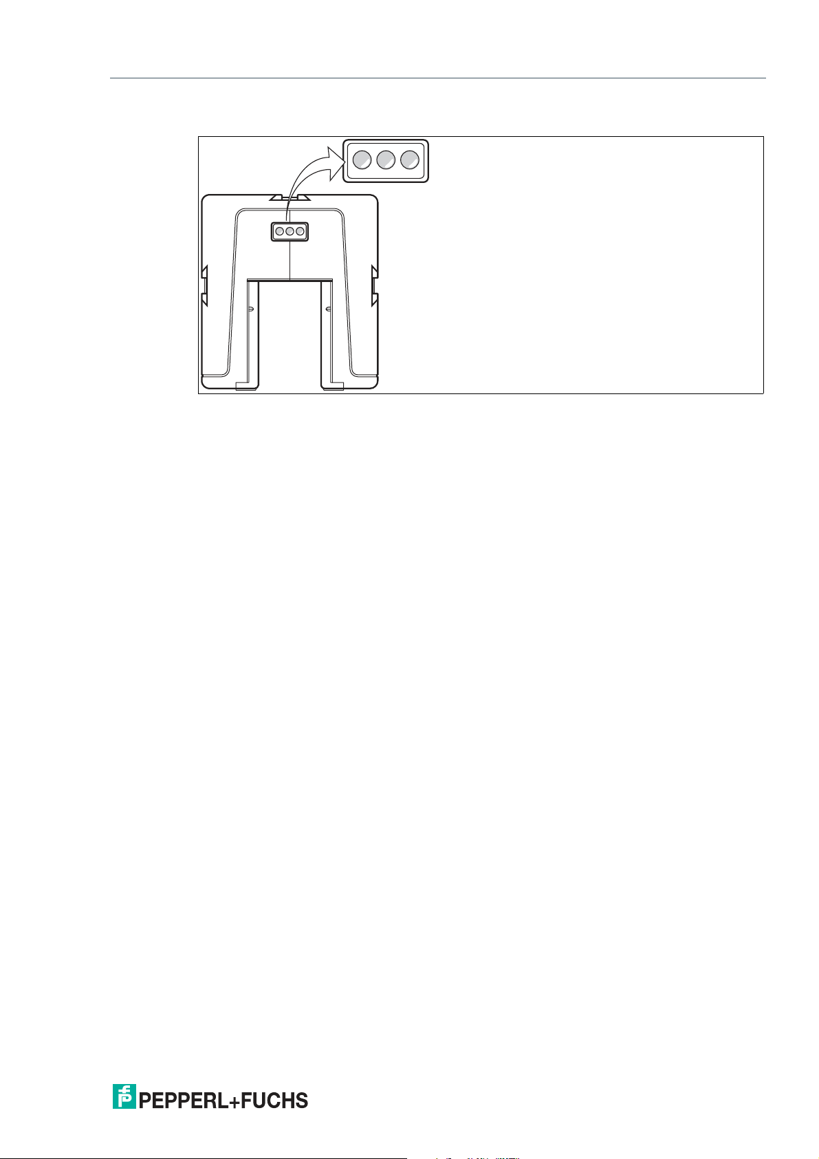
WCS3B-LS*E* (option—extended)
1 Yellow LED
2 Yellow LED
3 Dual LED green/red
Display Meaning
Data flow indicator LED 1 yellow
Flashing: Data transfer active
Off: No data transfer
Velocity display LED 2 yellow
On: Supply voltage applied
Off: Limit speed exceeded
Status indicator Dual LED 3 green/red
Green on: Code rail detected, normal function
Flashing green: Position invalid; code rail area is not
clear after the supply voltage has been connected
Red on: Internal diagnostic error
Flashing red: Read head partially or completely outside
the code rail
2020-01
29
Page 30
WCS* Read Head Position Encoding System
1
4
6
7
8
53
2
WCS2B-LS3xx
UB 10 ... 30 V
GND
CLK+
1
3
4
2
CLK-
DATA+
5
6
DATA-
Geschwindigkeitsausgang
*
)
I
out
= max. 150 mA
*
)
nur mit Option S, Geschwindigkeitsausgabe
WCS3B-LS3xx
UB 10 ... 30 V
GND
CLK+
1
3
4
2
7
CLK-
DATA+
5
6
DATA-
1
4
6
7
8
53
2
SSI Interface (LS3xx*)
5 SSI Interface (LS3xx*)
The read head with SSI interface supports data formats in gray code (LS311) or binary code
(LS310). Data transfer is carried out on the SSI read head at the request of the control panel.
5.1 Electrical Connection and Data Cables
Caution!
Property damage and system malfunctions due to incorrect pinout
Incorrect assignment of the wire pairs to the respective pins can result in property damage and
system malfunctions.
• Note the assignment of the wire pairs to the pins as shown in the respective wiring dia-
grams.
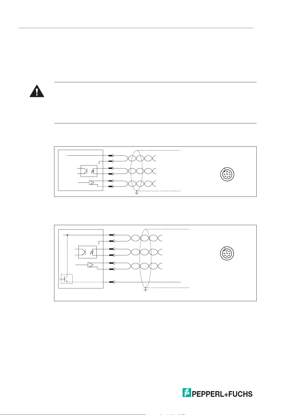
Connection diagram for WCS2B read head
The WCS2B read head with SSI interface is electrically connected via an 8-pin M12 plug.
Figure 5.1 WCS2B, SSI interface
Connection diagram for WCS3B read head
The WCS3B read head with SSI interface is electrically connected via an 8-pin M12 plug.
Figure 5.2 WCS3B, SSI interface
The counterpart of the plug connections, the 8-pin M12 socket, is not included in the scope of
delivery for the respective read head. You can obtain suitable connectors and cables from Pepperl+Fuchs, see chapter 12.1.
30
2020-01
Page 31
WCS* Read Head Position Encoding System
SSI Interface (LS3xx*)
Data cable
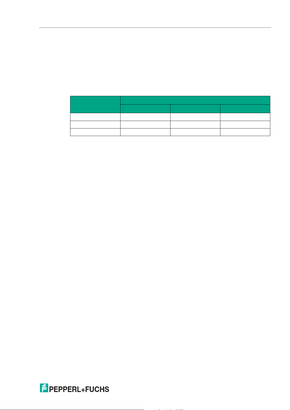
For SSI data transfer, a 6-wire, shielded, twisted pair data cable (3 x 2) is used. One wire pair is
used for the supply voltage, one pair for the CLK line, and one pair for the DATA line. The cable
lengths that are technically possible can be determined from the tables. For large cable lengths
(longer than 12 m) between the SSI read head and control panel, we recommend using the SSI
interface module. In this case, the data is transferred asynchronously from the read head to the
interface module via the RS-485 interface. The data is converted to SSI protocol immediately
next to the control panel. The table below shows the possible cable lengths depending on the
cable capacitance (core-core). The number of connected read heads is of no significance.
Capacitance
(core-core)
60 pF 200 m 100 m 30 m
90 pF 150 m 80 m 25 m
120 pF 100 m 60 m 20 m
SSI Interface
125 kHz 250 kHz 500 kHz
2020-01
31
Page 32
WCS* Read Head Position Encoding System
1
2
SSI Interface (LS3xx*)
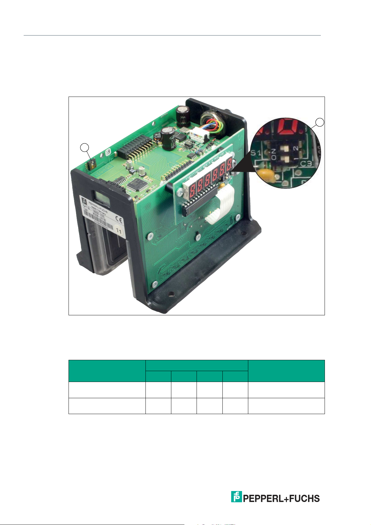
5.2 Hardware Configuration
You can change the hardware and software configuration of the read head in the read head.
The changes to the read head type are made with a DIP switch or with two if you have a read
head with the "Display" option: S1 (1) is a DIP switch with four switch positions and S1D (2) is a
DIP switch with two switch positions.
Figure 5.3 Configuration switch positions
1. Configuration switch S1, 4-way (data format, contamination detection)
2. Configuration switch S1D, 2-way (display)
Changing the data format
Configuration switch "S1"
Read head type
WCS2B-LS310
ON OFF X X Binary
Code1 2 3 4
WCS3B-LS310
WCS2B-LS311
OFF OFF X X Gray
WCS3B-LS311
2020-01
32
Page 33
WCS* Read Head Position Encoding System
SSI Interface (LS3xx*)
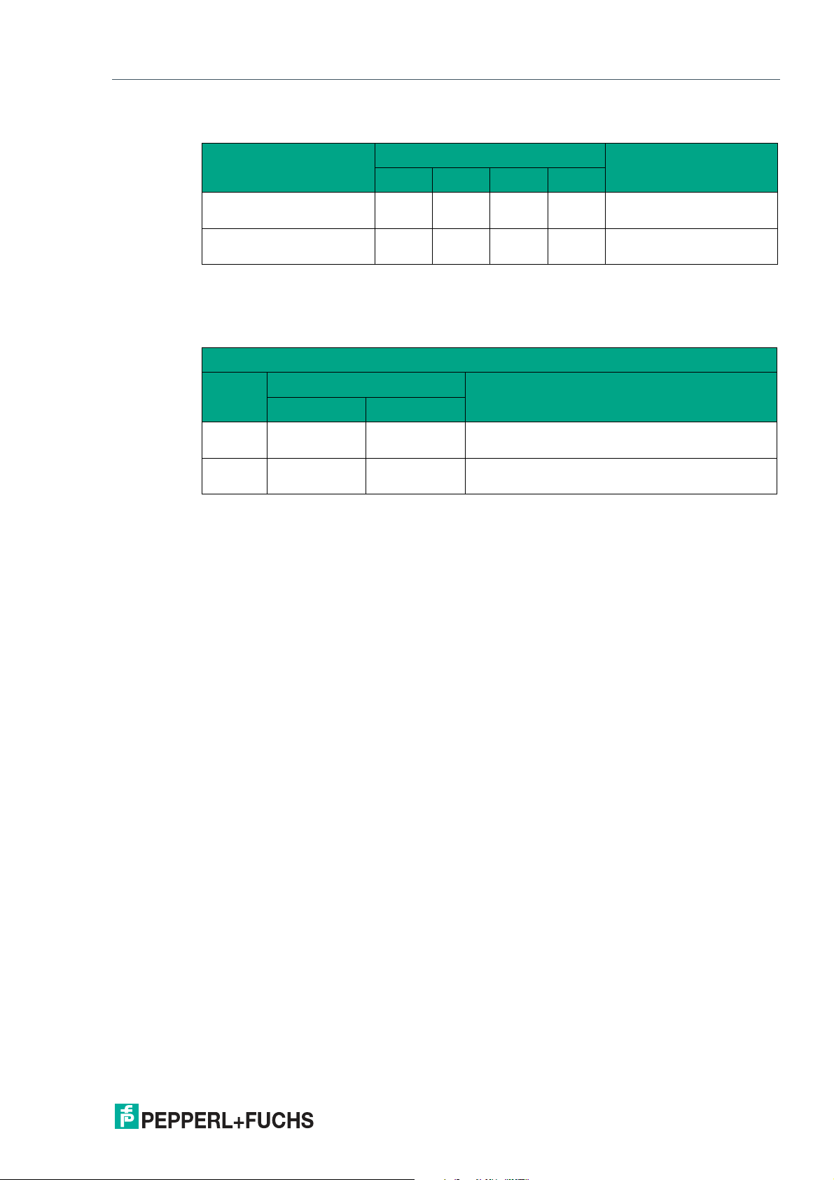
Output of a warning if the lenses are contaminated
Configuration switch "S1"
Read head type
WCS2B-LS31*
WCS3B-LS31*
WCS2B-LS31*
WCS3B-LS31*
X OFF X OFF ON
X OFF X ON OFF
Code1 2 3 4
Adjusting the Display
You can rotate the character position on the display 180° using the S1D DIP switch. This allows
you to read the displayed values easily regardless of the installation position of the read head.
WCS3B
Display
position
0° OFF OFF The displayed value can be read on a code rail
180° ON ON The displayed value can be read on a code rail
Configuration switch "S1D"
Comment1 2
mounted upright.
mounted suspended.
2020-01
33
Page 34
WCS* Read Head Position Encoding System
0 0 0 21821721621521421321221121029282726252423222120OA DB KB
MSB
LSB
1 2 3 4 5 6 7 8 9 10 11 12 13 14 15 16 17 18 19 20 21 22 23 24 25
CLK
BIT
DATA
SSI Interface (LS3xx*)
5.3 Data Protocols
The read head with SSI interface supports data formats in gray code (LS311) or binary code
(LS310). Data transfer for the SSI read head is carried out on request from the control panel.
SSI interface
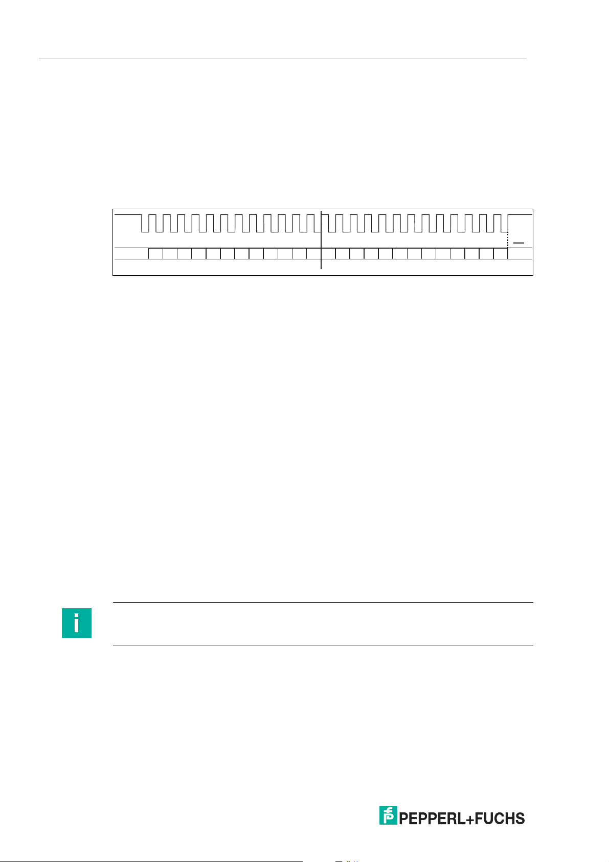
The clock signal (CLK) generated by the control panel is used for the transfer. If no data transfer begins, the serial data output of the read head remains at 1. The data transfer begins with a
falling edge of the clock signal. With each rising edge of the clock signal, the read head transmits one bit of the current position. The transfer begins with the most significant bit (MSB) and
ends with the least significant bit (LSB).
Figure 5.4 SSI data format
The read head with SSI interface corresponds to a 19-bit absolute encoder in the data format.
Effectively, the WCS read head delivers up to 512 revolutions and 1024 increments/revolution.
The clock rate between the control panel and the read head may be 100 ... 1000 kHz. The recommended value is 250 kHz.
Bit 1 ... 3
The first three bits are always 0.
Bit 4 ... 22 (218... 20 position values)
The position values are transferred to bits 4 to 22 of the SSI protocol. For LS311 read heads the
position values are gray encoded, and for LS310 read heads the position values are binary
encoded.
Bit 23 (OA read head outside the code rail)
A distinction is made between two different states:
1. The code rail is located in the read head gap, but outside the possible tolerances. In this
case, the control panel receives the following bit pattern:
KB = 0
OA = 0
POS 20 ... 218 = 1 (position value 524287)
2. There is no code rail in the read head gap. In this case, bit OA = 1 (Out All) is set in addition to the above bit pattern.
Note
Position data (bit 4 ... 22) are output for LS311 read heads in gray code. Status and error bits
(bit 23 ... 25) are not output in gray code.
34
2020-01
Page 35
WCS* Read Head Position Encoding System
SSI Interface (LS3xx*)
Bit 24 (DB output of a prewarning if the lenses are contaminated)
The contamination warning is transferred in bit 24 of the SSI protocol and can be evaluated.
The diagnostic bit DB is always switched on by default.
Read heads WCS2B and WCS3B continually monitor the condition of the lenses. If a drop in
light output is detected on the infrared transmitter, e.g., as a result of contamination of the clear
protective lenses, the read head automatically increases the light intensity. If the level of contamination is too high, a warning message is sent to the higher-level control panel (diagnostic
bit DB=1). The automatic light adjustment in the read head allows you sufficient time to clean
the read head as part of the next servicing procedure. The WCS3B read head emits a visual
signal for the "contamination detected" state: the yellow and red LEDs on the front of the read
head flash alternately. To clean the lenses, the read head must be removed from the code rail
(removed from the mounting base). After cleaning the transparent protective lenses, the contamination message is automatically deleted from the read head. If the message is not reset
despite careful cleaning or replacement of the plastic protective lenses, there may be an error.
In this case, the read head must be sent for inspection.
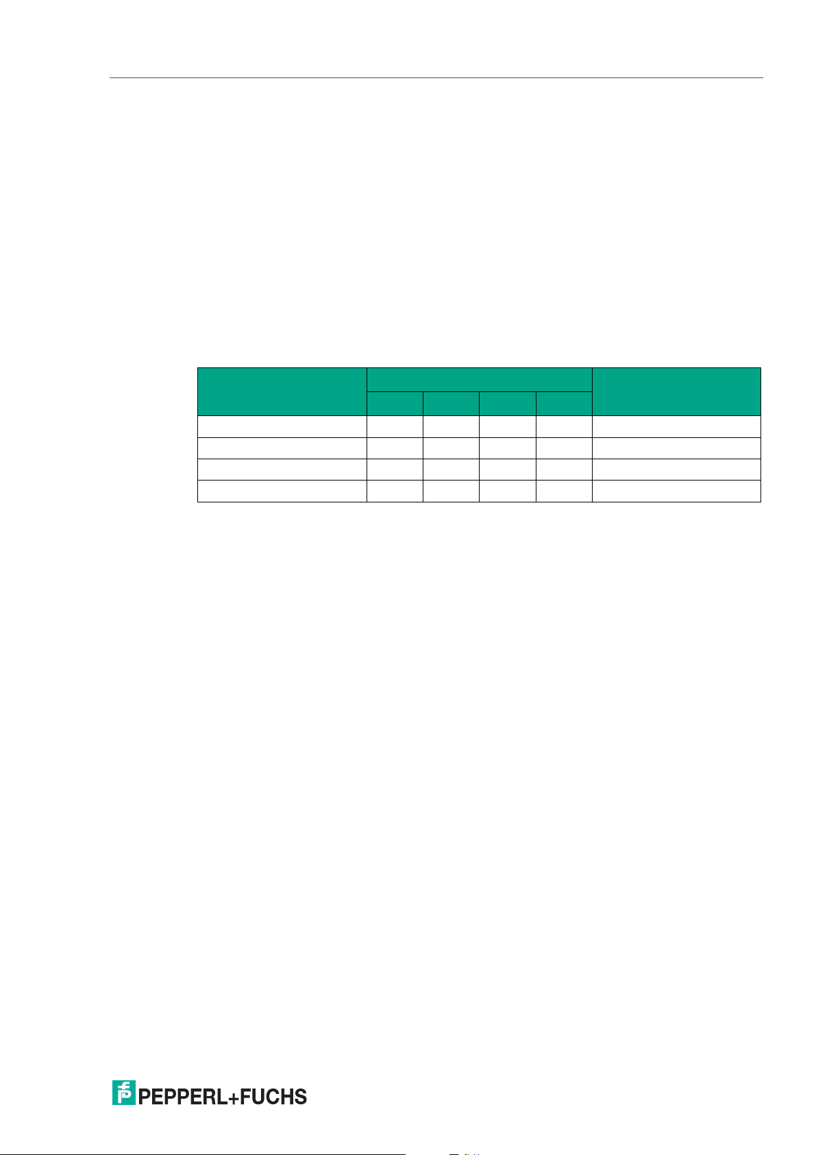
Read head type
(* = 0 or 1)
WCS2B-LS31* X OFF X OFF ON
WCS2B-LS31* X OFF X ON OFF
WCS3B-LS31* X OFF X OFF ON
WCS3B-LS31* X OFF X ON OFF
S1
1 2 3 4
Diagnostic bit
Bit 25 (KB error message)
If the read head detects an error, the KB error bit is set and the error code is output to the control panel:
KB = 1
POS 20 ... 22 = error number
POS 23 ... 218 = 0
Information on the error messages see chapter 5.4.
2020-01
35
Page 36
WCS* Read Head Position Encoding System
SSI Interface (LS3xx*)
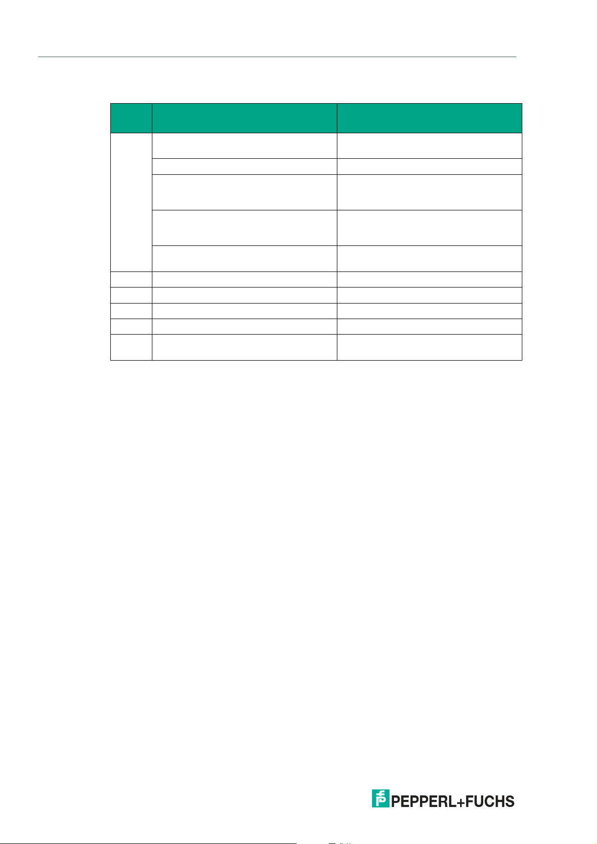
5.4 Status and Error Messages
Error
number Cause Remedy
1
2
3 RAM error, WCS read head Send WCS read head for repair
4 EPROM error, WCS read head Send WCS read head for repair
5 ROM error, WCS read head Send WCS read head for repair
6 Reserved
7 No position value available Message only after switching on the
WCS read head cannot calculate position
value because:
Optical unit is dirty Clean optical unit
Plastic protective lenses are scratched Align WCS read head and code rail cor-
Position of the read head in relation to the
code rail is incorrect
Light barriers have failed Check light barriers; if necessary send for
rectly; replace scratched plastic protective lenses
Check the position of the WCS read head
in relation to the code rail; install WCS
read head correctly
repair
WCS read head and/or after a RESET
36
2020-01
Page 37
WCS* Read Head Position Encoding System
1 2 3
SSI Interface (LS3xx*)
5.5 LED Status Indication
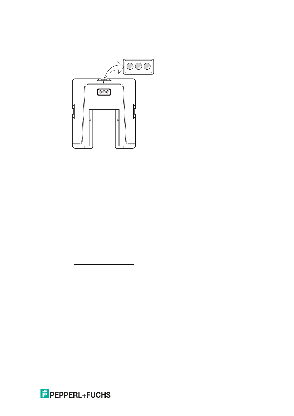
WCS3B-LS3xx*
1 Green LED
2 Yellow LED
3 Red LED
Display Meaning
Operating indicator Green LED: Power on
Data flow indicator
Velocity display
2
1
Yellow LED: Data transfer active
Yellow LED
Off if limit speed exceeded
Fault indicator Red LED
Flashing: Read head outside the code rail
Permanently lit: Internal diagnostic error
Contamination indicator Yellow LED and red LED flashing alternately: Read
head lens dirty (f=1.5 Hz)
Function indicator Yellow LED and red LED light up for 2 seconds after
power on or reset
1. Only for read heads with no velocity output
2. Only for read heads with velocity output
2020-01
37
Page 38
WCS* Read Head Position Encoding System
WCS3B-LS4xx
n.c.
CAN-H
CAN-L
1
2
3
4
5
120Ω
1
3
4
5
2
UB 10 ... 30 V
GND
CANopen Interface (LS4xx*)
6 CANopen Interface (LS4xx*)
The WCS3B read head with CANopen interface can be connected directly to a CANopen bus
after configuration. The configuration is made via DIP switches in the read head in a de-energized state.
The CAN interface is galvanically isolated. The read head works as a CANopen slave in the
"Predefined Connection Set" and sends the data in the TxPDO1.
6.1 Electrical Connection
Caution!
Property damage and system malfunctions due to incorrect pinout
Incorrect assignment of the wire pairs to the respective pins can result in property damage and
system malfunctions.
• Note the assignment of the wire pairs to the pins as shown in the respective wiring dia-
grams.
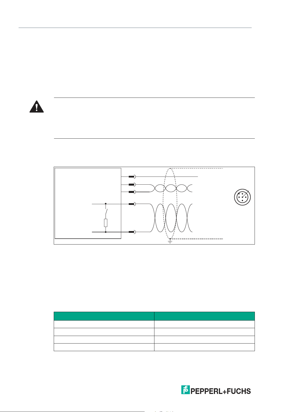
Connection diagram for WCS3B read head
The connection is made via a 5-pin M12 plug. The counterpart to the connector is not included
in the scope of delivery for the read head.
Figure 6.1 WCS3B, CANopen interface
You can obtain suitable connectors and cables from Pepperl+Fuchs, see chapter 12.1.
Data cable
For CANopen data transfer, a four-wire, shielded, twisted pair data cable must be used. One
wire pair is used for the supply voltage, and one wire pair is used for the CANopen data transfer.
The maximum length of the cable depends on the speed of the data transfer. The table below
shows the possible cable lengths depending on the bit rate.
38
Maximum cable length
Bit rate Cable length
125 kbits/s 500 m
250 kbits/s 250 m
500 kbits/s 100 m
1 Mbits/s 30 m
2020-01
Page 39
WCS* Read Head Position Encoding System
1
3
2
CANopen Interface (LS4xx*)
6.2 Hardware Configuration
You can change the hardware and software configuration of the read head in the read head.
The read head type is changed using three DIP switches.
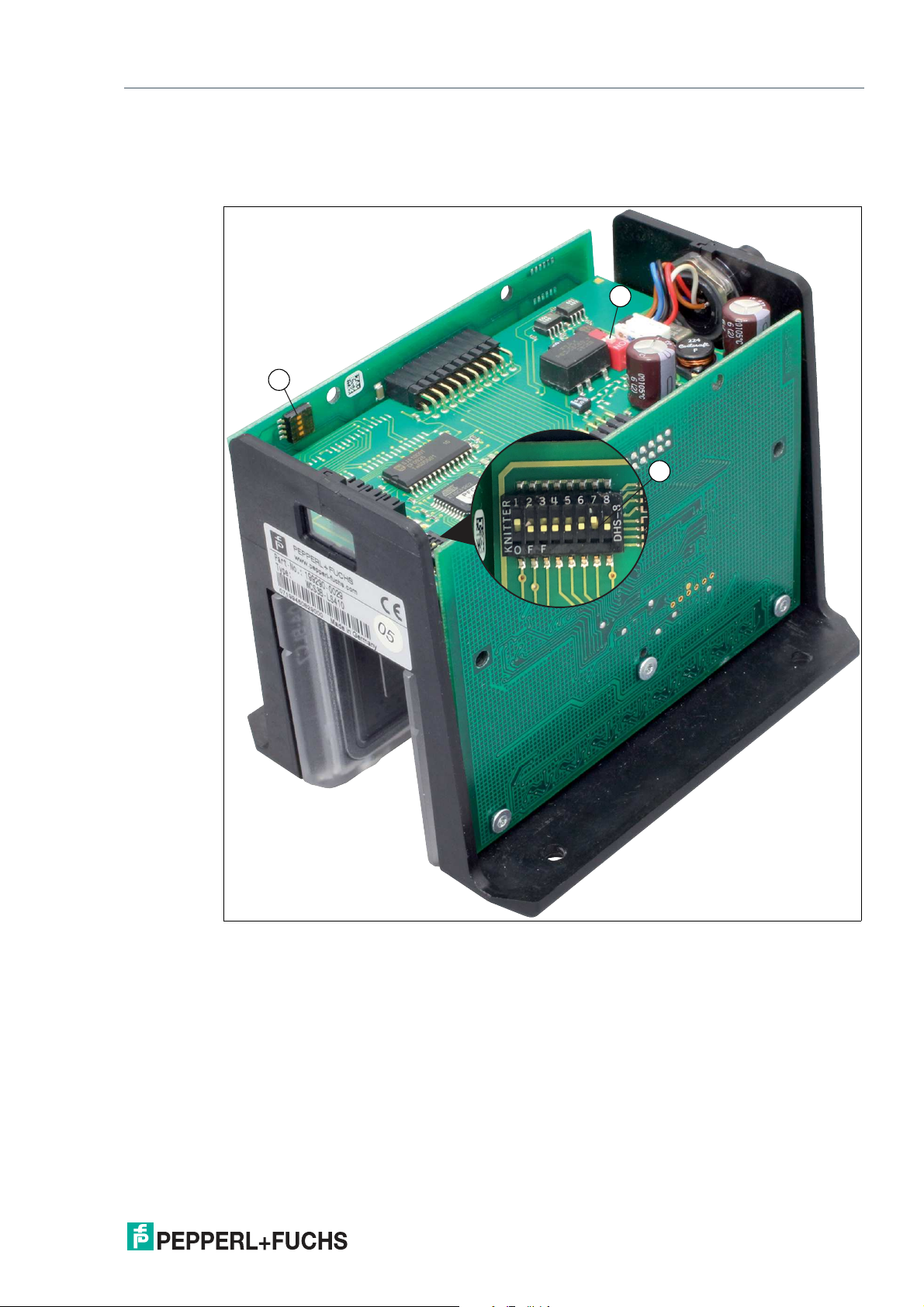
Figure 6.2 Configuration switch positions
1. 4-way configuration switch (transfer mode, data protocols)
2. 1-way configuration switch (CAN terminator)
3. 8-way configuration switch (baud rate, node ID)
CAN terminator
On the middle PCB in the read head there is a 1-way DIP switch (2). This switch can be used to
switch the CAN terminator, 120 ohms, off or on. The terminator is switched on by default.
Baud rate
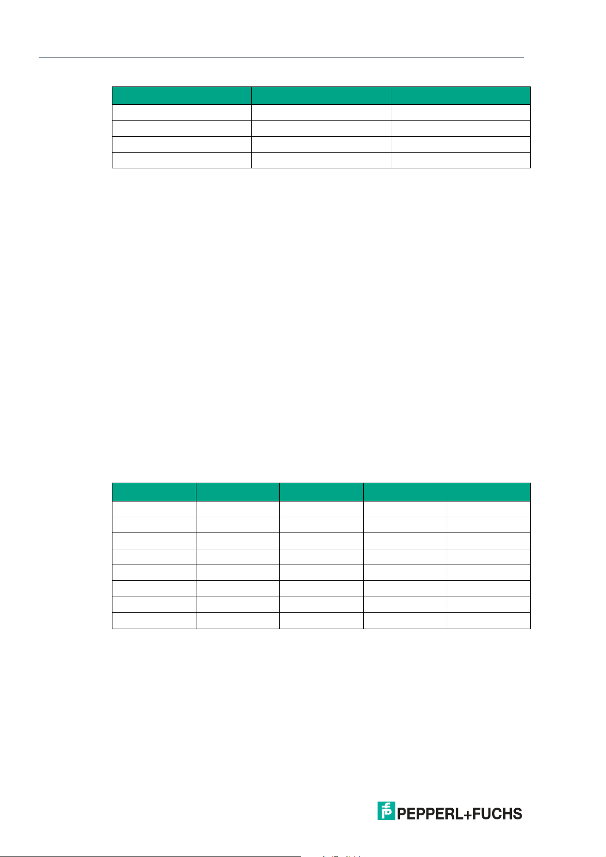
The baud rate can be changed using two switches of the 8-way DIP switch (3) on the central
PCB in the read head. The baud rate is 250 kBaud by default.
2020-01
39
Page 40
WCS* Read Head Position Encoding System
CANopen Interface (LS4xx*)
DIP 8-8 DIP 8-7 Baud rate
OFF OFF 125 kBaud
OFF ON 250 kBaud
ON OFF 500 kBaud
ON ON 1 MBaud
Node ID
The address in the CANopen bus, the node ID, can be changed using switches 1 to 6 of the 8way DIP switch (3) on the central PCB in the read head. The node ID is encoded in binary form.
The smallest possible node ID is 1, the highest possible node ID is 63. Node ID 0 is not permitted. Node ID 1 is applied by default.
Transfer mode in the CANopen bus
The transfer mode and the "inhibit time" can be configured using switches 1 to 3 of the 4-way
DIP switch (1) on the PCB on the side of the read head.
Asynchronous
Switch position 0 ... 3, see table below.
The read head automatically sends the data to the CAN bus as soon as this has changed in the
read head. However, a wait time of at least x ms must have passed since the last data packet.
This can prevent bus overload. If x = 0 ms, no waiting time is taken into account. In this case,
the maximum data rate to the CAN bus is approx. 1.5 ... 2 ms.
If the data in the read head does not change, it is sent to the CAN bus every y ms. Thus the
control panel receives data even if the vehicle is stationary.
Synchronous
Switch position 7, see table below.
The read head sends data after the SYNC command from the control panel. The typical delay
time after SYNC is 2 ms; the maximum delay time is 5 ms. By default, switch 1 - 3 = OFF, i.e.,
asynchronous data transfer 0 ms/10 ms.
Switch setting DIP4-3 DIP4-2 DIP4-1 x ms/y ms
0 OFF OFF OFF 0 ms/10 ms
1 OFF OFF ON 5 ms/20 ms
2 OFF ON OFF 10 ms/50 ms
3 OFF ON ON 20 ms/50 ms
4 ON OFF OFF Reserved
5 ON OFF ON Reserved
6 ON ON OFF Reserved
7 ON ON ON SYNC mode
Data Protocols
Two data protocols are supported: CAN data protocol 1 and CAN data protocol 2.
The data protocols always have a length of 8 bytes. The data protocol is selected via the fourth
switch of the 4-way DIP switch (1) on the PCB on the side of the read head.
DIP4-4 = OFF ... Can data protocol 1
DIP4-4 = ON ... CAN data protocol 2
2020-01
40
Page 41
WCS* Read Head Position Encoding System
CANopen Interface (LS4xx*)
6.3 Software Configuration
The read head is integrated into the network via an EDS file (electronic datasheet) with a project planning tool such as RSLogix 5000. The EDS file contains all information about devicespecific parameters and operating modes.
Note
Downloading the EDS file
You can find the relevant EDS file in the Software section of the product detail page for the
device.
To access the product detail page for the device, go to http://www.pepperl-fuchs.com and type
e.g., the product description or the item number into the search function.
6.4 Data Protocols
Two data protocols are supported: data protocol 1 and data protocol 2.
The data protocols always have a length of 8 bytes. The data protocol is selected via the fourth
switch of the 4-way DIP switch on the PCB on the side of the read head (see chapter 6.2).
• DIP4-4 = OFF ... CAN data protocol 1
• DIP4-4 = ON ... CAN data protocol 2
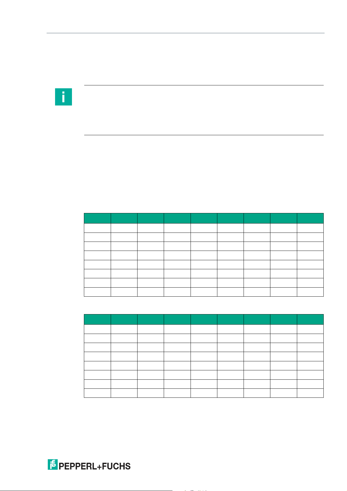
Data protocol 1
Bit Bit 7 Bit 6 Bit 5 Bit 4 Bit 3 Bit 2 Bit 1 Bit 0
Byte 0
Byte 1
Byte 2
Byte 3
Byte 4
Byte 5
Byte 6
Byte 7
0 0 0 0 0 P18 P17 P16
P15 P14 P13 P12 P11 P10 P09 P08
P07 P06 P05 P04 P03 P02 P01 P00
0 0 SST DB ERR OUT 0 0
0 SP6 SP5 SP4 SP3 SP2 SP1 SP0
0 0 0 0 0 0 0 0
0 0 0 0 0 0 0 0
0 0 0 0 0 0 0 0
Data protocol 2
Bit Bit 7 Bit 6 Bit 5 Bit 4 Bit 3 Bit 2 Bit 1 Bit 0
Byte 0
Byte 1
Byte 2
Byte 3
Byte 4
Byte 5
Byte 6
Byte 7
0 0 SST DB ERR OUT 0 0
P07 P06 P05 P04 P03 P02 P01 P00
P15 P14 P13 P12 P11 P10 P09 P08
0 0 0 0 0 P18 P17 P16
0 SP6 SP5 SP4 SP3 SP2 SP1 SP0
0 0 0 0 0 0 0 0
0 0 0 0 0 0 0 0
0 0 0 0 0 0 0 0
2020-01
41
Page 42
WCS* Read Head Position Encoding System
1 2 3
CANopen Interface (LS4xx*)
6.5 LED Status Indication
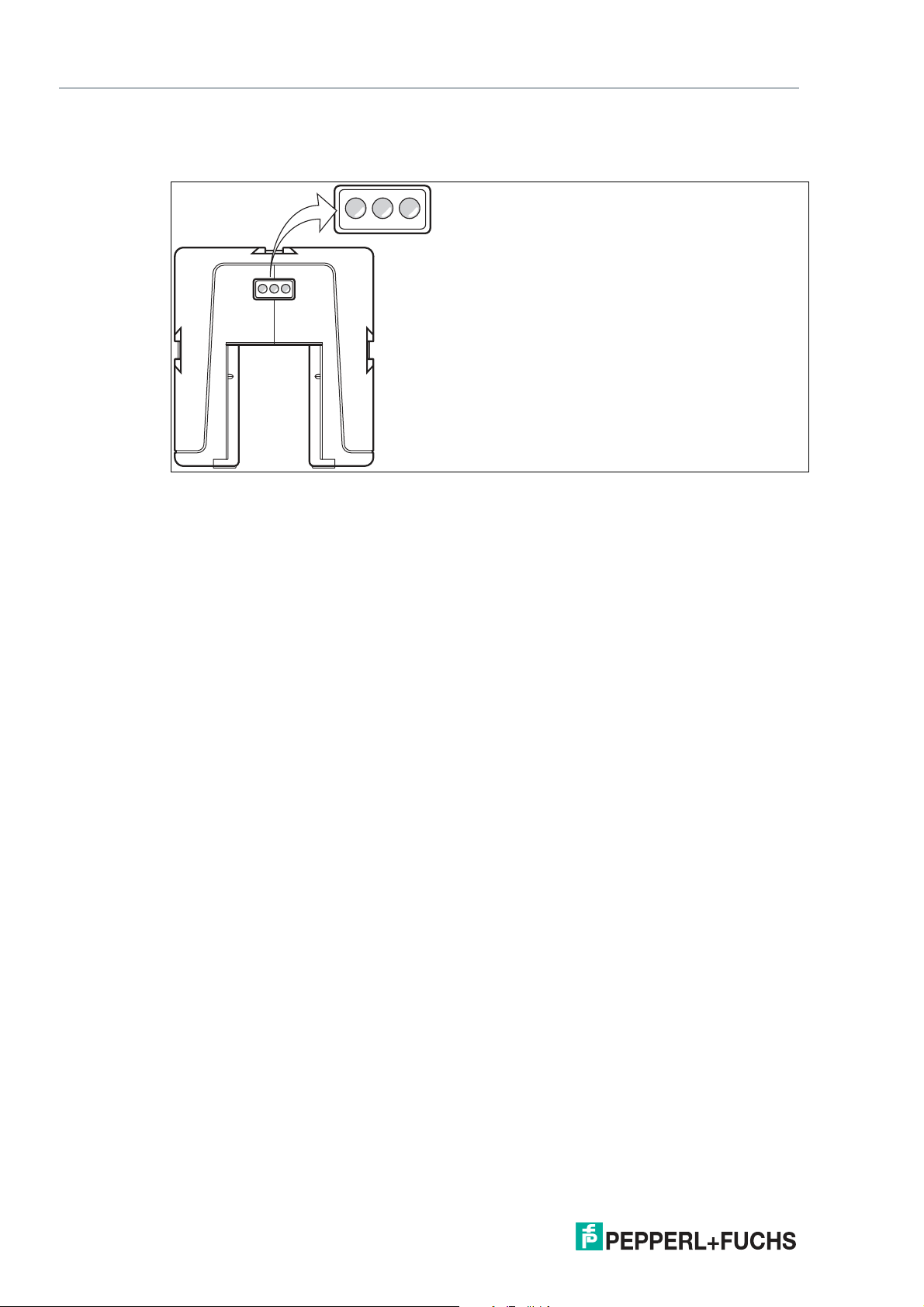
WCS3B-LS4xx*
1 Green LED
2 Yellow LED
3 Red LED
Display Meaning
Operating indicator Green LED: Power on
Data flow indicator Yellow LED: Data transfer active
Fault indicator Red LED
Contamination indicator Yellow LED and red LED flashing alternately: Read
Function indicator Yellow LED and red LED light up for 2 seconds after
Flashing: Read head outside the code rail
Permanently lit: Internal diagnostic error
head lens dirty (f=1.5 Hz)
power on or reset
42
2020-01
Page 43
WCS* Read Head Position Encoding System
1
2
3
4
13
4
5
2
6
7
8
5
6
7
8
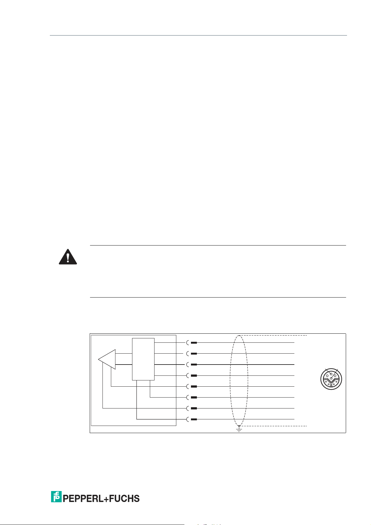
TX +
TX -
RX +
RX -
-UB
reserved
+UB
reserved
Interface
EtherNet/IP Interface (LS5xx*)
7 EtherNet/IP Interface (LS5xx*)
The read head communicates with the controller (e.g., PLC) via EtherNet/IP. An object-oriented
fieldbus system for exchanging data between nodes based on Ethernet communications.
The basic properties of the interface are:
• Transfer rate 10 Mbit/s or 100 Mbit/s, half or full duplex operation
• Automatic negotiation of the transfer rate and the duplex method (auto negotiation)
• Automatic setting for crossed lines (auto crossover)
EtherNet/IP protocol works according to the CIP protocol (Common Industrial Protocol) and is
used to control, configure, monitor, and collect data. Time-sensitive data exchange (implicit
messaging) takes place using the UDP/IP protocol and non-time-sensitive data exchange
(explicit messaging) using the TCP/IP protocol.
The read head supports the following features:
• "Listen only," "Input only," and "Exclusive Owner" connection types
• Message transmission as "Multipoint data transfer" (Multicast) and "Point-to-point data
transfer" (Unicast)
• Cycle time (request packet interval) 2 ms
• Dynamic Host Configuration Protocol (DHCP)
• Address Conflict Detection (ACD)
7.1 Electrical Connection
Caution!
Property damage and system malfunctions due to incorrect pinout
Incorrect assignment of the wire pairs to the respective pins can result in property damage and
system malfunctions.
• Note the assignment of the wire pairs to the pins as shown in the respective wiring dia-
grams.
Connection diagram for WCS3B read head
The WCS3B-LS5* read head is connected to EtherNet/IP and the power supply via an 8-pin
M12 socket with Y encryption.
2020-01
Figure 7.1 WCS3B, EtherNet/IP interface
Pins 6 and 8 are reserved for an internal interface and are connected to ground (-UB).
43
Page 44

WCS* Read Head Position Encoding System
1
2
3
4
3
2
1
4
1 2
3
4
1
4
5
7
1
2
3
4
5
6
7
8
12
3 4
8 6
3
2
EtherNet/IP Interface (LS5xx*)
Note
A shielded twisted pair cable that meets at least the CAT 5e/CAT 6 specification is used to
connect the read head to the control panel. The maximum recommended cable length is 75 m
for CAT 5e and 55 m for CAT 6. Longer distances are possible provided that the respective
specifications are observed. The connection can be implemented with various cable types
available from Pepperl+Fuchs.
Y-splitter
There are various options available for the electrical connection. A hybrid cable (see chapter
12.1) with a common data and supply line can be connected directly to the read head. Alternatively, data and supply lines can be routed separately with the Y-splitter.
Figure 7.2 V19SY-Y-V1D/V1: Y-splitter, M12 plug Y-encoded to M12 plug A-encoded and M12 socket
D-encoded
You can obtain the appropriate connectors and cables from Pepperl+Fuchs, see chapter 12.1.
44
2020-01
Page 45
WCS* Read Head Position Encoding System
2
1
EtherNet/IP Interface (LS5xx*)
7.2 Hardware Configuration
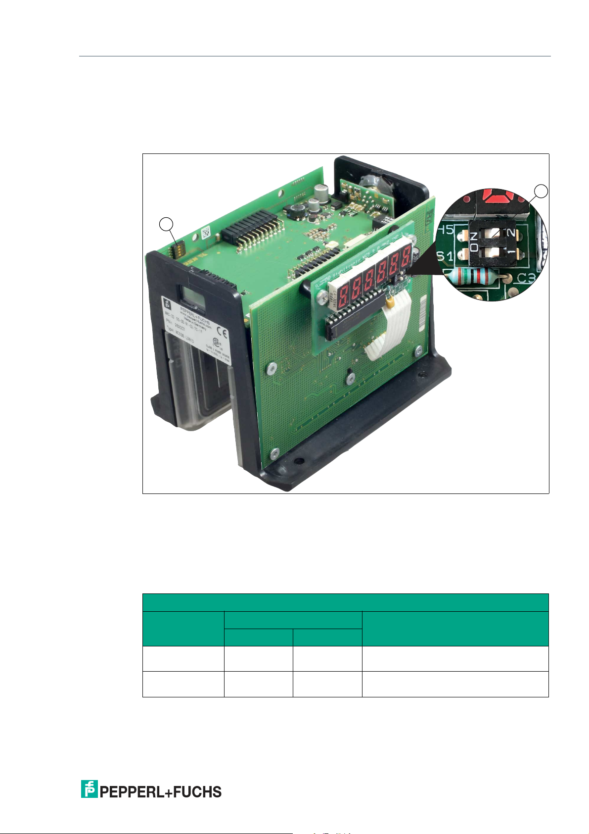
If you have a read head with the "Display" option, a DIP switch with two switches S1D (2) is
installed. This DIP switch allows you to change the display. The 4-way DIP switch (1) in the figure below does not work. The firmware parameters of the read head are set via the corresponding project planning software.
Figure 7.3 Configuration switch positions
1. Configuration switch S1, 4-way (no function)
2. Configuration switch S1D, 2-way (display)
Adjusting the Display
2020-01
You can rotate the character position on the display 180° using the S1D DIP switch. This allows
you to read the displayed values easily regardless of the installation position of the read head.
WCS3B
Configuration switch "S1D"
Display position
Comment1 2
0° OFF OFF The displayed value can be read on a
code rail mounted upright.
180° ON ON The displayed value can be read on a
code rail mounted suspended.
45
Page 46
WCS* Read Head Position Encoding System
EtherNet/IP Interface (LS5xx*)
7.3 Software Configuration
The read head communicates with the control panel (e.g., PLC) via EtherNet/IP, an object-oriented fieldbus system for exchanging data between nodes based on Ethernet communications.
The read head is integrated into the network via an EDS file (electronic datasheet) with a project planning tool such as RSLOGIX5000. The EDS file contains all information about devicespecific parameters and operating modes.
Note
Downloading the EDS file
You can find the relevant EDS file in the Software section of the product detail page for the
device.
To access the product detail page for the device, go to http://www.pepperl-fuchs.com and type
e.g., the product description or the item number into the search function.
Setting the IP address
The read head is delivered in DHCP mode and waits for an address assignment from the control panel.
The following section describes the process of assigning an address via the BOOT/DHCP
Server from Rockwell Automation as an example.
1.
Connect the read head with the DHCP server.
2.
Start the BOOT/DHCP server software.
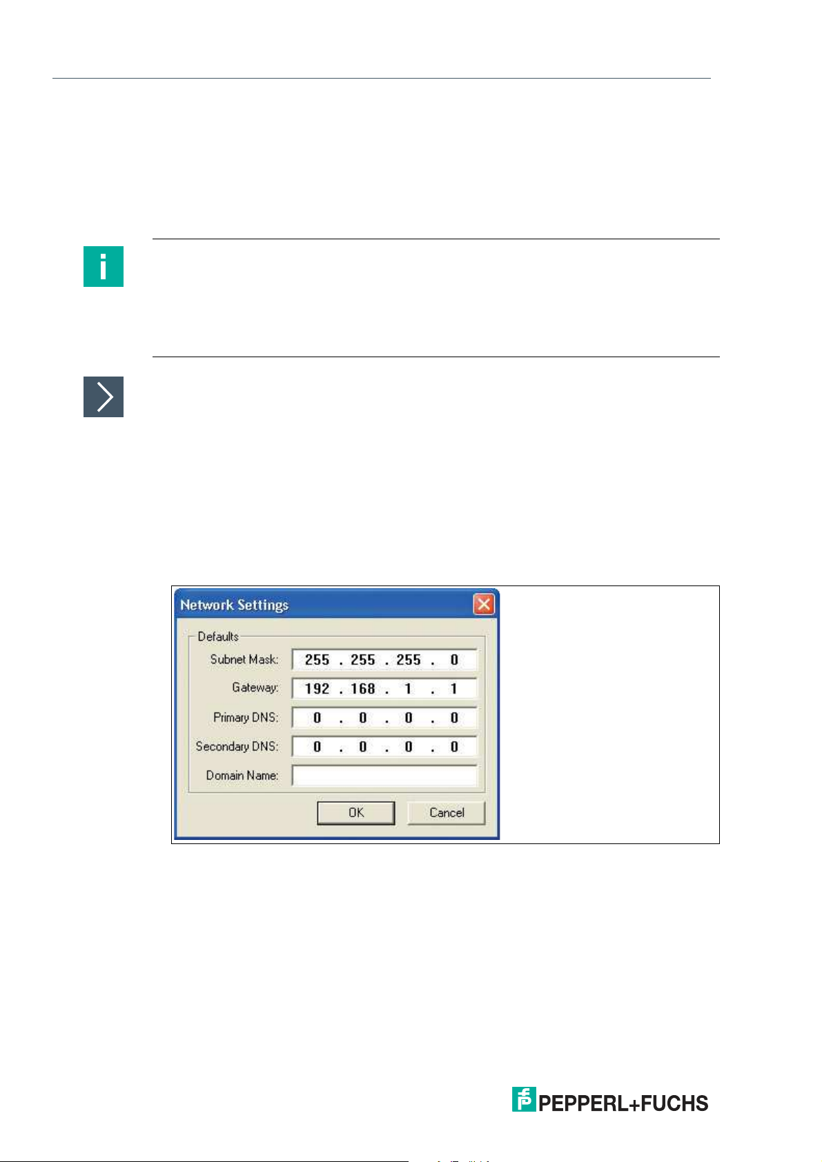
3.
Enter the following data in the Network Settings menu:
- Subnet Mask "255.255.255.0"
- Gateway "192.168.1.1"
- The remaining fields are not filled in.
4.
Switch on the supply voltage to the read head.
46
2020-01
Page 47
WCS* Read Head Position Encoding System
EtherNet/IP Interface (LS5xx*)
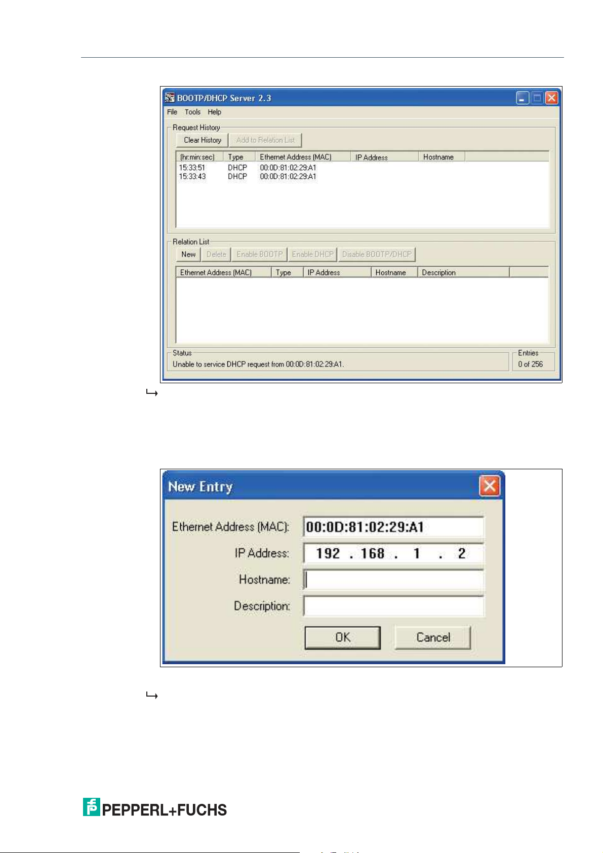
The read head cyclically carries out DHCP requests. The MAC address of the read head is
entered in the list in the Request History field.
5.
Enter the desired IP address in the New Entry menu.
- The software automatically adopts the MAC address of the read head.
- The "hostname" function is not supported.
- You may enter text under "Description."
6.
Confirm the entries of the address data using OK.
The IP address is assigned to the read head on the next DHCP request. The new address
data will be displayed in the Relation List field.
2020-01
47
Page 48
WCS* Read Head Position Encoding System
EtherNet/IP Interface (LS5xx*)
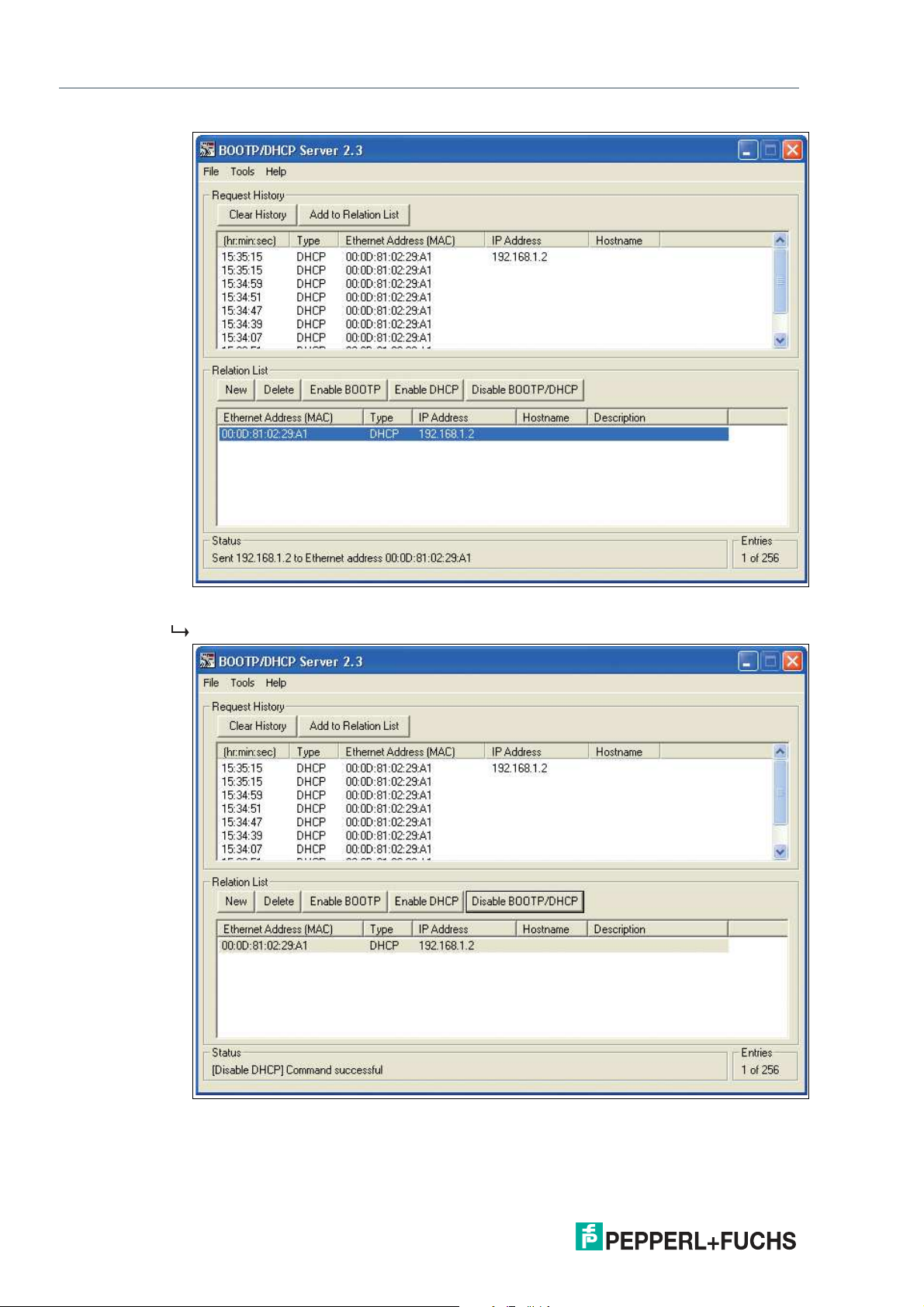
7.
Press the Disable BOOTP/DHCP key in the Relation List field.
In this way, the assigned IP address is saved permanently in the read head.
48
2020-01
Page 49
WCS* Read Head Position Encoding System
EtherNet/IP Interface (LS5xx*)
7.4 Data Protocols
EtherNet/IP objects
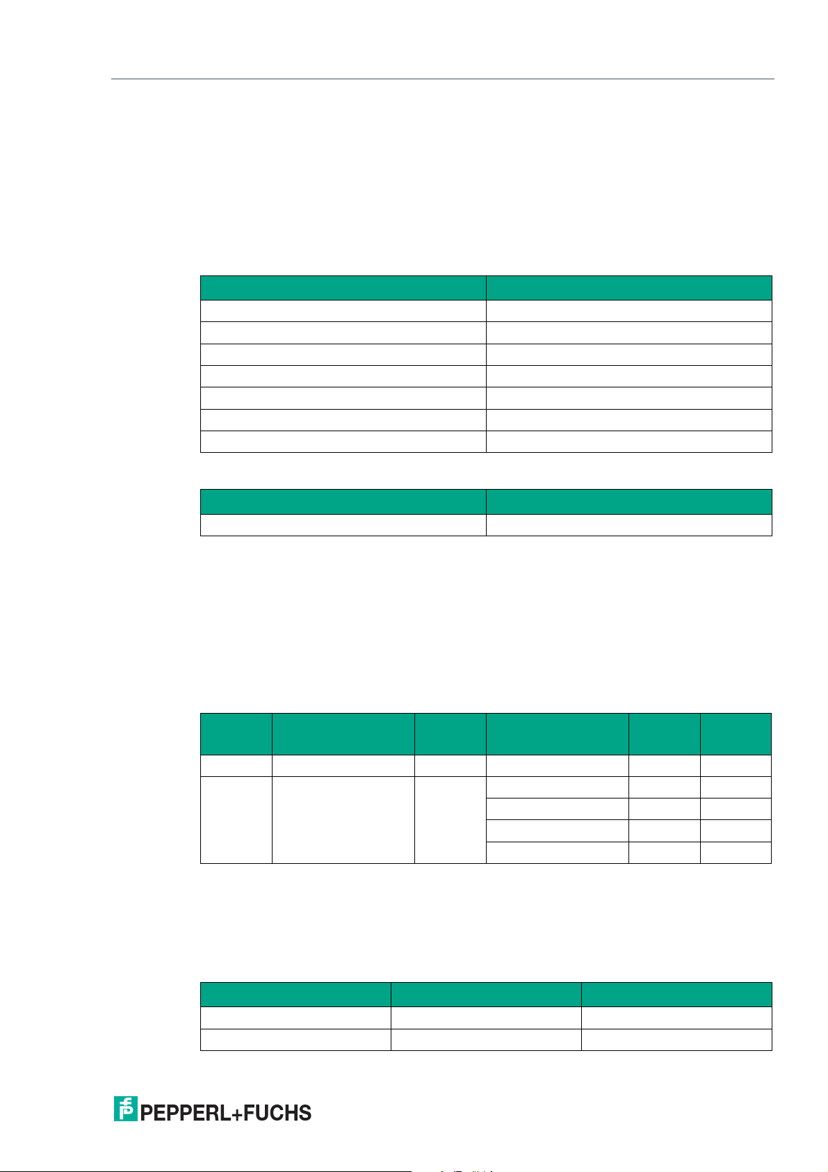
All the data and functions of the read head are defined via objects in accordance with the EtherNet/IP standards. The read head corresponds to the "Encoder Device Type 0x22" device
profile.
The read head supports the following listed standard and product-specific classes.
Standard classes
Class ID Class name
0x01 Identity Object
0x02 Message Router Object
0x04 Assembly Object
0x06 Connection Manager Object
0xF5 TCP/IP Interface Object
0xF6 Ethernet Link Object
0x48 Quality of Service
Product-specific class
Class ID Class name
0x23 Position Sensor Object
The parameters are not directly addressable from the network with the "Set" or "Get" attribute
services. Access is via assembly objects (Class Code 0x04)
Cyclic data communication with assembly objects (Class Code 0x04)
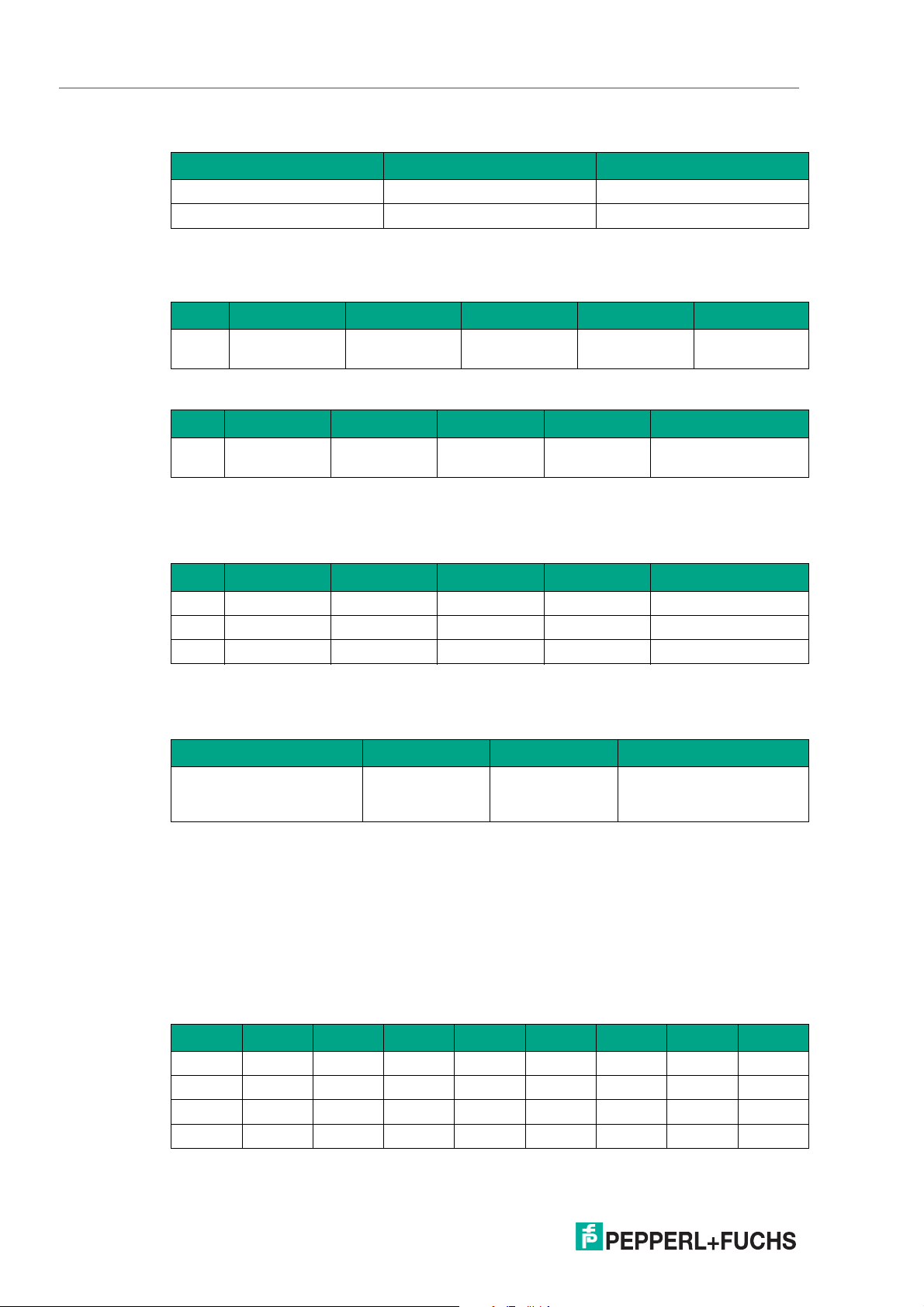
Assemblies are special CIP objects used for cyclic data communication (implicit messaging).
These are composed of one or more attributes of various objects. These objects allow you to
send or receive data from multiple objects via a connection. The composition of the assemblies
in the read head is fixed and cannot be modified by the user.
Input assemblies
Instance
no. Description
1 Position 4 Position Value Signed 10 DINT
100 Status, position, veloc-
ity, faults
Size
[byte] Attribute
7 Position Value Signed 10 DINT
Status Word 100 USINT
Velocity Value 101 USINT
Error Value 102 USINT
Attribute
ID Data type
Addresses required for the various connection types
The connection type defines the connection between the control system (originator), in this
case the controls, and the target device (target), in this case the read head. The following
options are available for data traffic.
Data from the control system to the target device
Instance no. (dec.) Size [byte] Connection type
192 0 Listen only
193 0 Input only
2020-01
49
Page 50
WCS* Read Head Position Encoding System
EtherNet/IP Interface (LS5xx*)
Data from the target device to the control system
Instance no. (dec.) Size [byte] Assemblies
1 4 Position
100 7 Status, position, velocity, faults
Attributes of the Position Sensor Object (Class ID 0x23)
Class attributes
ID Name Access Data type Size [byte] Description
1 Revision - UINT 2 Object inspec-
Standard instance attributes for object 0x23
ID Attribute Access Data type Size [byte] Description
10 Position Value
Signed
- DINT 4 Position value signed
tion
The parameters are not directly addressable from the network with the "Set" or "Get" attribute
services. You can change the parameters by using assemblies.
Specific read head attributes
ID Attribute Access Data type Size [byte] Description
100 Status Word - USINT 1 Status information
101 Velocity - USINT 1 Velocity in dm/s
102 Error - USINT 1 Fault if content 0
Basic data structure
1 byte = 8 bit value
Byte 4 Byte 3 Byte 2 Byte 1
Example: XP31 ... XP24
MSB (most significant
byte)
Example: XP23
... XP16
Example: XP15
... XP08
Example: XP07 ... XP00
LSB (least significant byte)
Position data X: Position Value Signed (ID 10)
Size Type Content
4 byte consistent Input data 32-bit X data
LSB first
LSB = least significant byte
At a resolution of 0.8 mm: L
mm
= 314.5 m = 314,500
max
50
Data for attribute 10
Bit 7 Bit 6 Bit 5 Bit 4 Bit 3 Bit 2 Bit 1 Bit 0
Byte 1 XP07 XP06 XP05 XP04 XP03 XP02 XP01 XP00
Byte 2 XP15 XP14 XP13 XP12 XP11 XP10 XP09 XP08
Byte 3 XP23 XP22 XP21 XP20 XP19 XP18 XP17 XP16
Byte 4 XP31 XP30 XP29 XP28 XP27 XP26 XP25 XP24
2020-01
Page 51
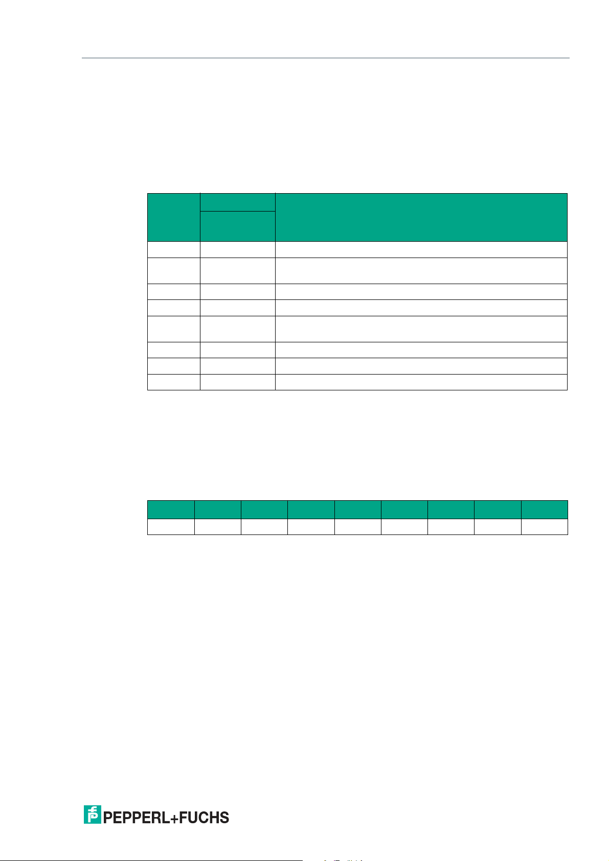
WCS* Read Head Position Encoding System
EtherNet/IP Interface (LS5xx*)
Status: Status word (ID 100)
Size Type Content
1 byte Input data 8 bit status
If the ERR bit is set, there is an error. The error number is transmitted to the "Error value (ID
102)" attribute.
Data for attribute 100
Content
Byte 1
Bit no.
1 ERR Error message, error code in ERR00 – ERR07
2 OUT Read head partially outside the code rail. No valid position avail-
3 OUTALL Read head completely outside the code rail.
4 DB Diagnostic bit. Read head dirty.
5 SST Speed status. If the speed status = 1 then the current velocity is
6 Reserved -
7 Reserved -
8 Reserved -
Status
Function
able.
unknown. The specified velocity value is invalid.
Speed: velocity value (ID 101)
Size Type Content
1 byte consistent Input data 8 bit speed data
LSB first
Information in dm/s
Data for attribute 101
Bit 7 Bit 6 Bit 5 Bit 4 Bit 3 Bit 2 Bit 1 Bit 0
Byte 1 SP07 SP06 SP05 SP04 SP03 SP02 SP01 SP00
2020-01
51
Page 52
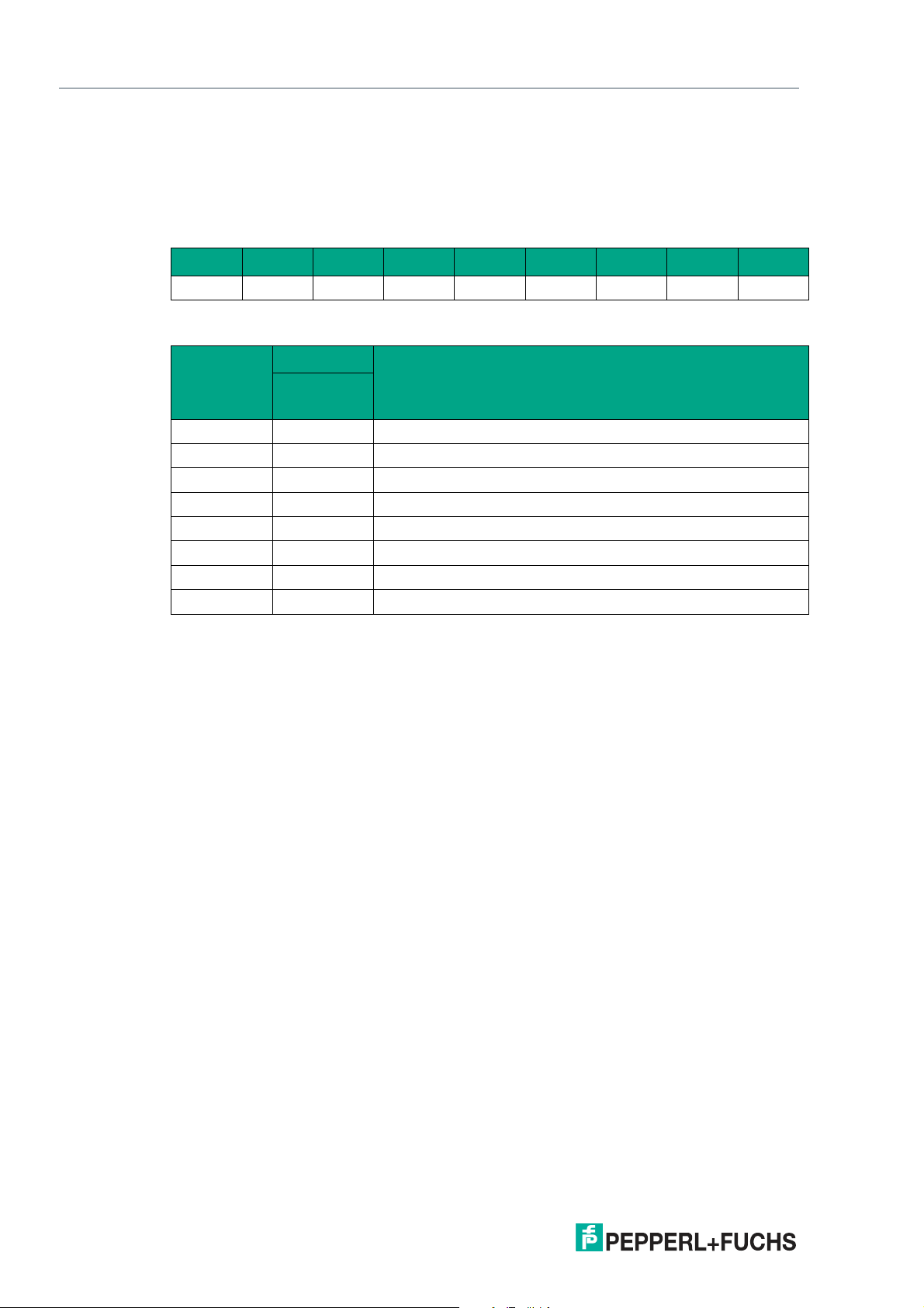
WCS* Read Head Position Encoding System
EtherNet/IP Interface (LS5xx*)
Faults: error value (ID 102)
Size Type Content
1 byte consistent Input data 8 bit fault data
Data for attribute 102
Bit 7 Bit 6 Bit 5 Bit 4 Bit 3 Bit 2 Bit 1 Bit 0
Byte 1 ERR7 ERR6 ERR5 ERR4 ERR3 ERR2 ERR1 ERR0
A binary encoded value in attribute 100 means that the corresponding fault is active.
Content
Byte 1
Value
0 Error 0 -
1 Error 1 Current position cannot be determined.
2 Error 2 Current position cannot be determined.
3 Error 3 Fault in the RAM working memory.
4 Error 4 Fault in the EPROM memory or in the decoder.
5 Error 5 Fault in the ROM memory.
6 Error 6 -
7 Error 7 -
Status
Function
52
2020-01
Page 53
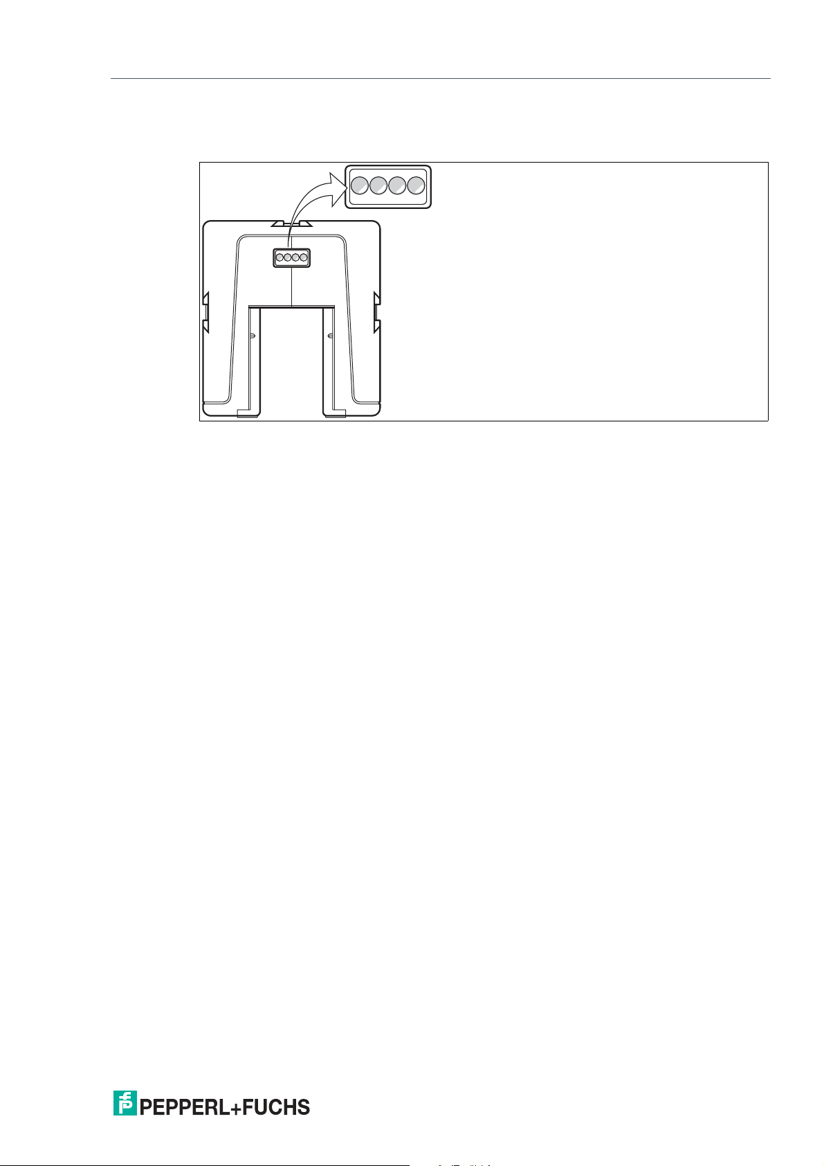
WCS* Read Head Position Encoding System
21 3 4
EtherNet/IP Interface (LS5xx*)
7.5 LED Status Indication
WCS3B-LS5xx*
1 Dual red/green LED
2 Green LED
3 Yellow LED
4 Red LED
Display Meaning
Status indicator Dual red/green LED
Ethernet link Green LED
Ethernet RX/TX Yellow LED
Ethernet communication Red LED
Green: Code rail detected, normal function
Red: System error
Flashing red: No code rail detected
On: Fieldbus connection OK
Flashing: Data transfer
On: Communication error
2020-01
53
Page 54
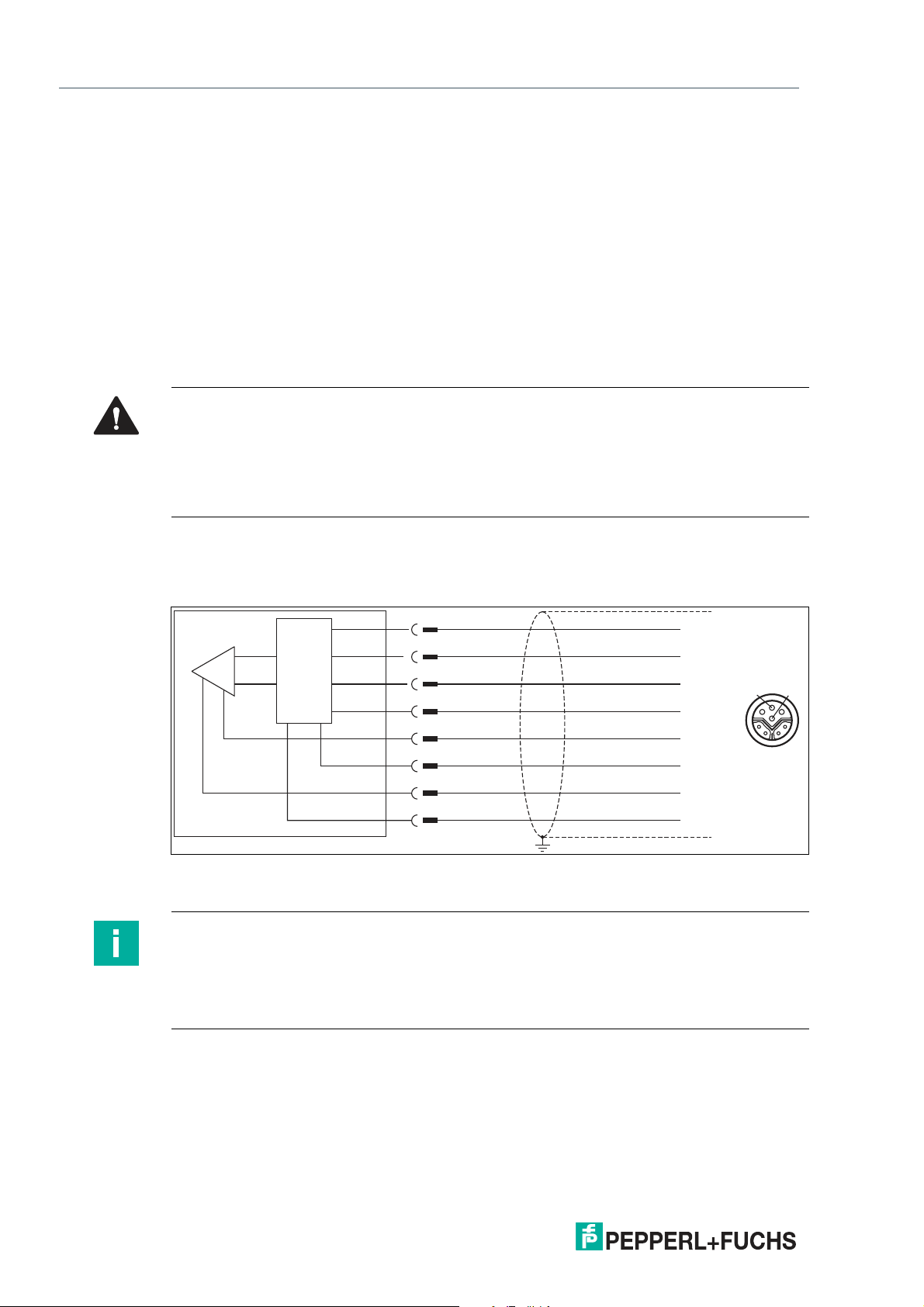
WCS* Read Head Position Encoding System
1
2
3
4
13
4
5
2
6
7
8
5
6
7
8
TX +
TX -
RX +
RX -
-UB
reserved
+UB
reserved
Interface
PROFINET Interface (LS6xx*)
8 PROFINET Interface (LS6xx*)
The WCS3B-LS6xx* read heads are PROFINET I/O devices that communicate cyclically with
the assigned PROFINET I/O controller during operation.
The PROFINET interface of the WCS3B-LS6xx* read heads supports:
• A transfer rate of 100 Mbit/s
• The real-time category RT
• The range of functions in accordance with Conformance Class B
• The identification and maintenance functions (I&M) IM0 – IM4
8.1 Electrical Connection
Caution!
Property damage and system malfunctions due to incorrect pinout
Incorrect assignment of the wire pairs to the respective pins can result in property damage and
system malfunctions.
• Note the assignment of the wire pairs to the pins as shown in the respective wiring dia-
grams.
Connection diagram for WCS3B read head
The WCS3B-LS6* read head is connected to PROFINET and the power supply via an 8-pin
M12 socket with Y encryption.
Figure 8.1 WCS3B, PROFINET interface
Pins 6 and 8 are reserved for an internal interface and are connected to ground (-UB).
Note
A shielded twisted pair cable that meets at least the CAT 5e/CAT 6 specification is used to
connect the read head to the control panel. The maximum recommended cable length is 75 m
for CAT 5e and 55 m for CAT 6. Longer distances are possible provided that the respective
specifications are observed. The connection can be implemented with various cable
connections available from Pepperl+Fuchs.
54
2020-01
Page 55
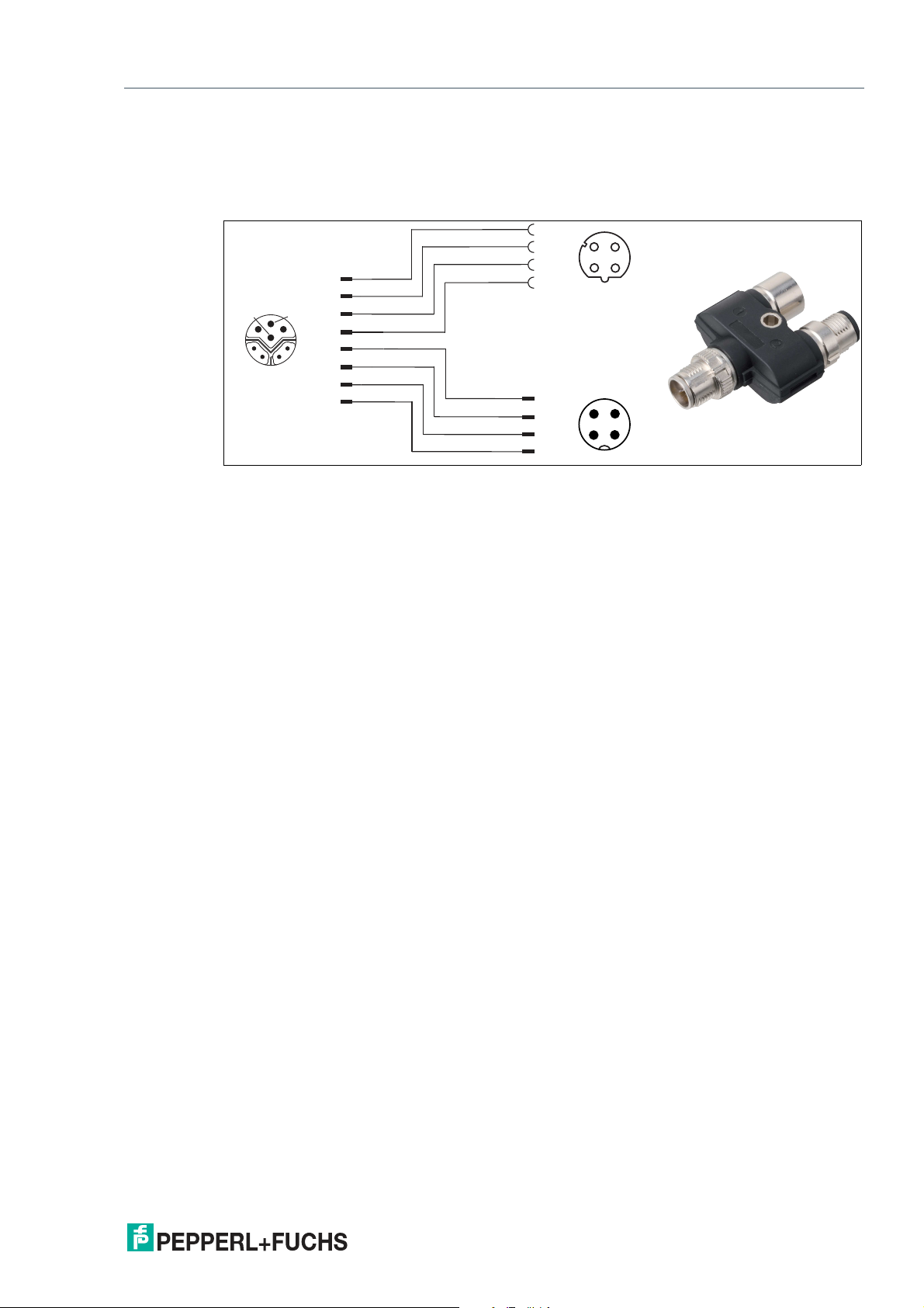
WCS* Read Head Position Encoding System
1
2
3
4
3
2
1
4
1 2
3
4
1
4
5
7
1
2
3
4
5
6
7
8
12
3 4
8 6
3
2
PROFINET Interface (LS6xx*)
Y-splitter
There are various options available for the electrical connection. A hybrid cable (see chapter
12.1) with a common data and supply line can be connected directly to the read head. Alternatively, data and supply lines can be routed separately with the Y-splitter.
Figure 8.2 V19SY-Y-V1D/V1: Y-splitter, M12 plug Y-encoded to M12 plug A-encoded and M12 socket
D-encoded
You can obtain the appropriate connectors and cables from Pepperl+Fuchs, see chapter 12.1.
2020-01
55
Page 56
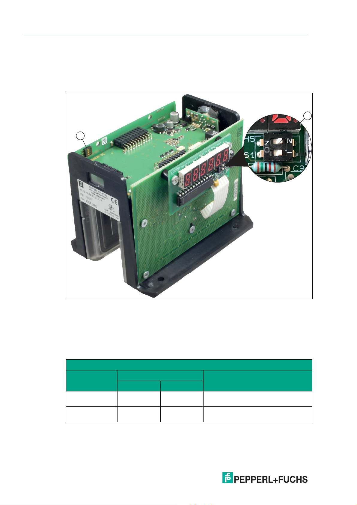
WCS* Read Head Position Encoding System
2
1
PROFINET Interface (LS6xx*)
8.2 Hardware Configuration
If you have a read head with the "Display" option, a DIP switch with two switches S1D (2) is
installed. This DIP switch allows you to change the display. The 4-way DIP switch (1) in the figure below does not work. The firmware parameters of the read head are set via the corresponding project planning software.
Figure 8.3 Configuration switch positions
1. Configuration switch S1, 4-way (no function)
2. Configuration switch S1D, 2-way (display)
Adjusting the Display
You can rotate the character position on the display 180° using the S1D DIP switch. This allows
you to read the displayed values easily regardless of the installation position of the read head.
WCS3B
Configuration switch "S1D"
Display position
Comment1 2
0° OFF OFF The displayed value can be read on a
code rail mounted upright.
180° ON ON The displayed value can be read on a
code rail mounted suspended.
2020-01
56
Page 57

WCS* Read Head Position Encoding System
PROFINET Interface (LS6xx*)
8.3 Software Configuration
PROFINET is an open standard for industrial automation based on industrial Ethernet. PROFINET integrates information technology with established standards such as TCP/IP and XML in
automation technology.
Within PROFINET, PROFINET IO is the communication concept for the construction of decentralized applications. This means that read heads are integrated through PROFINET IO. The
familiar IO view of PROFIBUS DP is used where the usable data of the read heads is transferred to the process image of the control panel in cycles. PROFINET IO is a device model consisting of slots and channels, which is based on the main features of PROFIBUS DP. The
properties of the read heads are written in a Generic Station Description Markup Language
(GSDML) based on XML. PROFINET IO is engineered in such a way that the read heads are
assigned to a control panel in project planning.
PROFINET IO distinguishes between the following three device types:
• IO controller: Controller that executes the automation program.
• IO device: Decentrally assigned field device that is assigned to an IO controller.
• IO supervisor: Programming unit/PC with commissioning and diagnostic functions.
The read head functions as a PROFINET I/O device that communicates cyclically with the
assigned PROFINET I/O controller during operation.
Project planning using device description
The read head is integrated into the project planning tool by way of a device description. The
field device properties are described in the GSDML file. The GSDML file contains the data of
the field device that you need to operate the device in a PROFINET network. You import the
GSDML file into a project planning tool that you use to configure the read head settings. Once
project planning is complete, the control panel receives the project planning data and configuration data.
Downloading the GSDML file
You can find the relevant GSDML file in the Software section of the product detail page for the
device.
To access the product detail page for the device, go to http://www.pepperl-fuchs.com and type
e.g., the product description or the item number into the search function.
PROFINET address and identifying a device
Every read head has a unique device identification. This device identification consists of the following:
• A unique MAC address. This MAC address is printed on the back of the device.
• A device name. The default device name is wcs3b-ls610.
• An IP address. The default IP address is 192.168.2.2.
2020-01
57
Page 58
WCS* Read Head Position Encoding System
PROFINET Interface (LS6xx*)
Identification & maintenance—calling up and editing data
Identification & maintenance data (I&M data) is information stored in a device. I&M data
uniquely identifies a device within a plant. The identification data (I data) includes information
about the device, for example the item number and device name. Identification data cannot be
changed.
Maintenance data (M data) includes information about the device within the plant, for example
the installation location and installation date. Maintenance data is initially stored in the device
during installation. Maintenance data can be changed.
The Step7 software from Siemens can be used to display and change the I&M data.
1.
To do so, open the hardware configuration HW Config and call up the "Target system" menu.
2.
Open one of the following functions:
• "Download module identification"
• "Download module identification in PG"
Figure 8.4
3.
Depending on the requirement, read or edit the following I&M data:
• I&M data 1: plant designation, location designation
• I&M data 2: installation date
• I&M data 3: additional information
58
2020-01
Page 59
WCS* Read Head Position Encoding System
PROFINET Interface (LS6xx*)
8.4 Data Protocols
The WCS3B-LS6xx* read heads are PROFINET I/O devices that communicate cyclically with
the assigned PROFINET I/O controller during operation.
The PROFINET interface of the WCS3B-LS6xx* read heads supports:
• A transfer rate of 100 Mbit/s
• The real-time category RT
• The range of functions in accordance with Conformance Class B
• The identification and maintenance functions (I&M) IM0 – IM4
Modules with response telegram
The following modules enable read head data to be retrieved using PROFINET.
Position Data X Module
Size Type Content
2 words, consistent
Input data 32-bit X data
MSB first
MSB = most significant byte
Resolution: 0.8 mm, binary coded
L
314.5 m = 314500 mm
max =
Response
Content
Word 1
Bit no.
1 XP16 XP00
2 XP17 XP01
3 XP18 XP02
4 0 XP03
5 0 XP04
6 0 XP05
7 0 XP06
8 0 XP07
9 0 XP08
10 0 XP09
11 0 XP10
12 0 XP11
13 0 XP12
14 0 XP13
15 0 XP14
16 0 XP15
X data
Word 2
X data
2020-01
59
Page 60
WCS* Read Head Position Encoding System
PROFINET Interface (LS6xx*)
Speed data module
Size Type Content
1 byte Input data 8 bit speed data
Response
Bit no.
1 SP00
2 SP01
3 SP02
4 SP03
5 SP04
6 SP05
7 SP06
8 SP07
Resolution: 0.1 m/s, binary coded
Speed of 0 ... 12.5 m/s
Example: Speed = 4.7 m/s --> speed output = 47 with
resolution 0.1 m/s
126 for speed > 12.5 m/s
127 for unknown speed
Content
Word 1
Speed
Error message module
Size Type Content
1 byte Input data 8 bit numerical value
ERR messages
Content
Byte 1
Error
0 ERR00 -
1 ERR01 Current position cannot be determined
2 ERR02 Current position cannot be determined
3 ERR03 Fault in the working memory (RAM)
4 ERR04 Fault in the EPROM memory or in the decoder
5 ERR05 Fault in the ROM memory
6 ERR06 -
7 ERR07 -
Status
Function
ERR message from 0 ... 7
Example: ERR message = 00000001 = Error 1
Error 1 corresponds to "Current position cannot be
determined"
60
Status module
Size Type Content
1 byte Input data 8 bit status
2020-01
Page 61
WCS* Read Head Position Encoding System
PROFINET Interface (LS6xx*)
Response
Content
Byte 1
Bit no.
1 ERR Error message, see error codes ERR00 – ERR07
2 OUT Read head partially outside the code rail. No valid posi-
3 OUTALL Read head completely outside the code rail.
4 DB Diagnostic bit. Read head dirty.
5 SST Speed status
6 Reserved -
7 Reserved -
8 Reserved -
Status
Function
tion available.
2020-01
61
Page 62
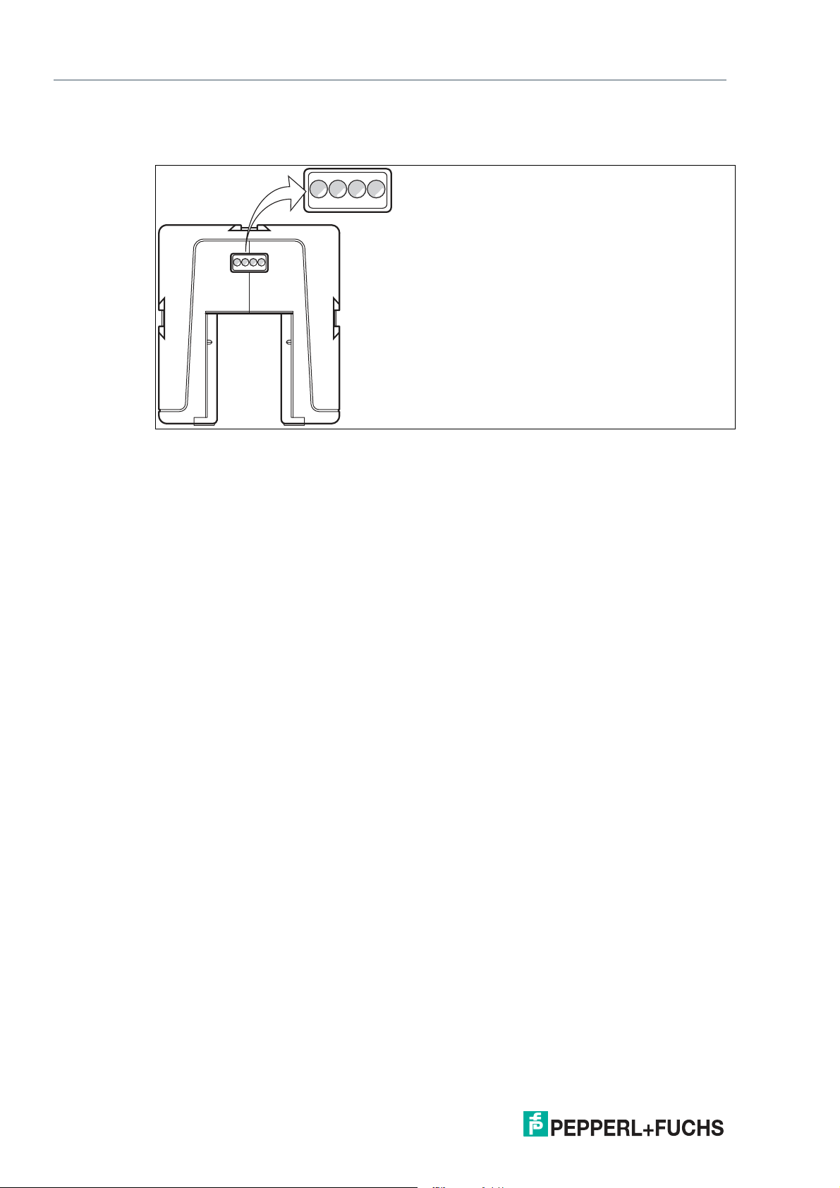
WCS* Read Head Position Encoding System
21 3 4
PROFINET Interface (LS6xx*)
8.5 LED Status Indication
WCS3B-LS6xx*
1 Dual red/green LED
2 Green LED
3 Yellow LED
4 Red LED
Display Meaning
Status indicator Dual red/green LED
Ethernet link Green LED
Ethernet RX/TX Yellow LED
Ethernet communication Red LED
Green: Code rail detected, normal function
Red: System error
Flashing red: No code rail detected
On: Fieldbus connection OK
Flashing: Data transfer
On: Communication error
62
2020-01
Page 63
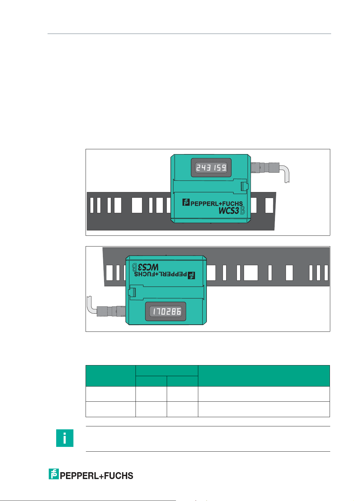
WCS* Read Head Position Encoding System
M12
M12
Options and Special Functions
9 Options and Special Functions
9.1 Option D—Integrated Display in the Read Head, Type LS...D
Integrated Display Module
The WCS3B reader can be equipped with an optional display module or can be retrofitted at
the factory. During the reader's movements, the display module reports the current position
value and any error messages. If the reader has been stationary for more than 15 seconds, the
display module issues additional diagnostics data alternately with the position value in a rotating cycle. (See the WCS catalog).
You can rotate the character position on the display 180° using the S1D DIP switch. This allows
you to read the displayed values easily regardless of the installation position of the reader.
Figure 9.1 Display for a perpendicular code rail (position 0°)
Figure 9.2 Display for a suspended code rail (position 180°)
Adjusting the display with configuration switch S1D
S1D
Display position
0° OFF OFF The displayed value can be read on a code rail
180° ON ON The displayed value can be read on a code rail
Comment1 2
mounted upright.
mounted suspended.
Note
The set display position is not noted on the nameplate of the read head.
2020-01
63
Page 64

WCS* Read Head Position Encoding System
Options and Special Functions
Overview of the display module
The display shows the current position value. After switching on the read head, the following
information is displayed in sequence:
read head type, e.g., "LS-221"
read head address, e.g., "Addr 0"
software version, e.g., "Pr. 1.01"
When at a standstill, the read head switches to the "information display" mode. The following
data is displayed cyclically:
"12.34.56," internal clock (hh.mm.ss)
"Good" or "bad"
Condition of the lens/photoelectrics:
"LE - - -," No error message
"LE 1," Read head has detected error 1
"Lo --- ," Read head was not outside the code rail
"Lo 34," Read head was outside the code rail 34 times
"LS ---," Limit speed has not been exceeded
"LS 128," Limit speed was exceeded 128 times (only for read head with option "velocity out-
put")
Note
All values are reset after the voltage is switched on. The maximum time is 99:59:59, then the
time starts again at 00:00:00. The maximum counter values for Lo and LS are 255.
64
2020-01
Page 65
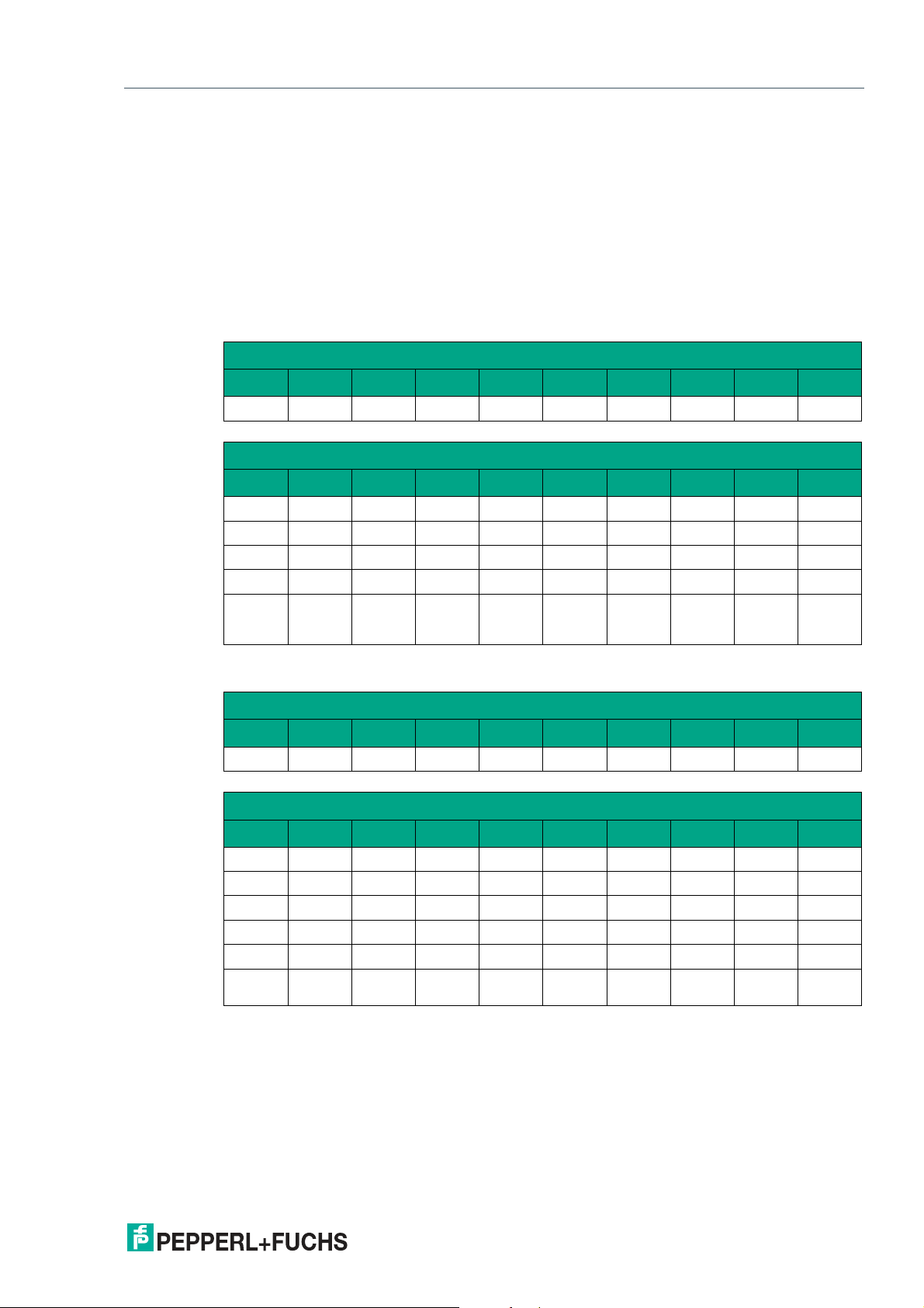
WCS* Read Head Position Encoding System
Options and Special Functions
9.2 Option-E—Extended, Type WCS3B-LS2*E*, RS-485
The read head WCS3-Extended: WCS3B-LS*E* with RS-485 interface is used for routes of
more than 314.573 m. In this case, the additional "E" in the type code identifies the extended
version for the extending code rail. Two standard code rail segments with a length of
0 ... 314.573 m are connected to each other with the WCS3-CS70-E code rail extender to
achieve a maximum code rail length of up to 629.146 m. The first code rail segment must
always be complete, or end with the position at 314.573 m. The second code rail segment can
have a shorter length of 314.573 m to X m, but must be used in descending position, starting at
314.573 m.
Extended data protocol with position output
Request byte for read head
Byte Bit 8 Bit 7 Bit 6 Bit 5 Bit 4 Bit 3 Bit 2 Bit 1 Bit 0
1 0 1 1 0 0 1 A1 A0
Response telegram from the read head
Byte Bit 8 Bit 7 Bit 6 Bit 5 Bit 4 Bit 3 Bit 2 Bit 1 Bit 0
Byte 1 0
Byte 2 0
Byte 3 0
Byte 4 0
Byte 5 0
A1 A0 OVL /VAL DB OUT ALL OUT ERR
0 0 0 0 XP19 XP18 XP17 XP16
XP15 XP14 XP13 XP12 XP11 XP10 XP09 XP08
XP07 XP06 XP05 XP04 XP03 XP02 XP01 XP00
xor
B1.7..B4
.7
xor
B1.6..B4
.6
xor
B1.5..B4
.5
xor
B1.4..B4
.4
xor
B1.3..B4
.3
xor
B1.2..B4
.2
xor
B1.1..B4
.1
xor
B1.0..B4
.0
Data protocol with position and velocity output
Request byte for read head
Byte Bit 8 Bit 7 Bit 6 Bit 5 Bit 4 Bit 3 Bit 2 Bit 1 Bit 0
1 1 1 1 0 0 1 A1 A0
Response telegram from the read head
Byte Bit 8 Bit 7 Bit 6 Bit 5 Bit 4 Bit 3 Bit 2 Bit 1 Bit 0
Byte 1 0
Byte 2 0
Byte 3 0
Byte 4 0
Byte 5 0
Byte 6 0
A1 A0 OVL /VAL DB OUT ALL OUT ERR
0 0 0 0 XP19 XP18 XP17 XP16
XP15 XP14 XP13 XP12 XP11 XP10 XP09 XP08
XP07 XP06 XP05 XP04 XP03 XP02 XP01 XP00
SST SP6 SP5 SP4 SP3 SP2 SP1 SP0
B1.7..B5.7B1.6..B5.61.5..B5.5 B1.4..B5.4B1.3..B5.3B1.2..B5.2B1.1..B5.1B1.0..B5
.0
2020-01
65
Page 66

WCS* Read Head Position Encoding System
Options and Special Functions
Description of the protocol data
Byte 1
A1, A0 Address bits of the read head. Addresses 0 ... 3, binary coding
OVL 0 The read head is located in the readable area of the code rail
1 The read head is located on WCS3 code rail extender (overlapping
area of the code rail segments)
VAL 0: Position valid
1 Position invalid; code rail area is not unique after the supply voltage
has been connected
DB 0 By default, the diagnostic bit is not set
1 Diagnostic bit, read head dirty
OUT ALL 0 Read head in code rail
1 Read head completely outside of the code rail
OUT 0 Read head in code rail
1 Read head partially outside the code rail. No valid position available
ERR 0 No error
1 Error message (possible errors in XP00 ... XP01 binary coding)
Byte 2 ... 4
XP00 ... XP19 Current position value, binary coding
Byte 5
1
SP0 ... SP6 Current speed in 0.1 m/s, binary coding
Example:
• 1: Speed = 0.1 m/s
• 37: Speed = 3.7 m/s
• 112: Speed = 11.2 m/s
SST 0 Speed valid
1 Current speed unknown. Last valid speed in SP0 ... SP6 saved
Byte 5/6 Exclusive or link, byte 1 ... Byte 4/5
1. For data protocol with velocity output
66
2020-01
Page 67
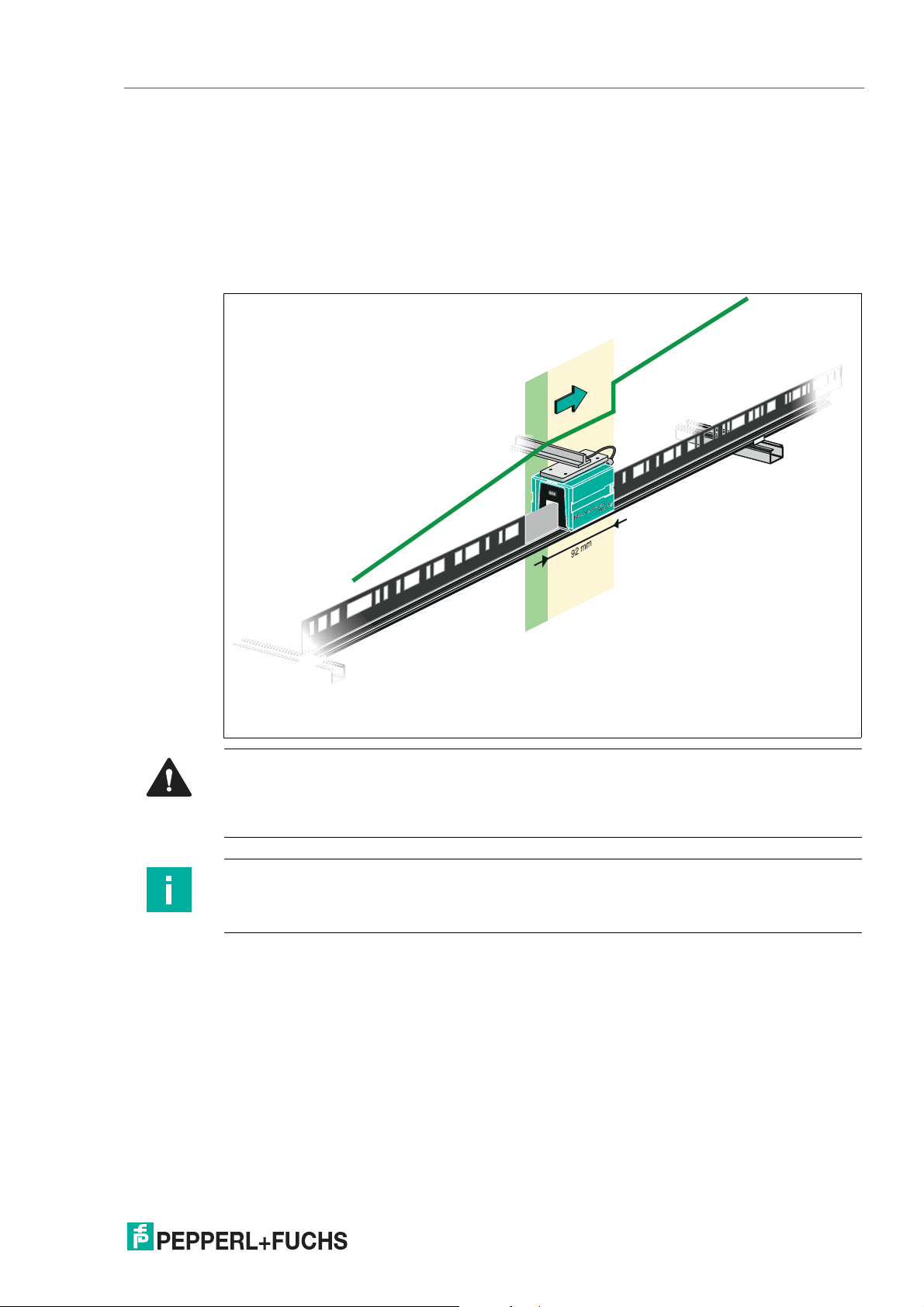
WCS* Read Head Position Encoding System
Options and Special Functions
Behavior of the read head in the area of the WCS3 code rail extender
(WCS3-CS70-E)
The read head retains the last measured end position of the first code rail segment (position =
393203) when traversing the WCS3 code rail extender. The OVL bit is set at the same time. As
soon as the first valid position of the second code rail segment is read, the read head switches
to the first valid position of the second code rail segment (position = 393318). The first valid
position of the second code rail segment is dimensioned with an offset of approx. + 92 mm
(see area highlighted in yellow in the figure below).
Caution!
Impermissible state
If you mount the WCS3 code rail extender in the wrong position, e.g., at an intermediate position of the code rail, the OUT bit is set when this code rail segment is crossed.
Note
Cycle time
Note that the cycle time for the extended variant differs from the standard variant by t = 10 ms.
Start-up behavior of the read head
After the supply voltage has been connected, the X position is set to the last valid X position
and the VAL bit is set to 1.
The speed value is 127 and the SST bit is set to 1.
After the read head moves by approx. 5 mm, the VAL bit is set to 0 and the X position is
assigned a new calculated X position. The last valid X position is stored in a non-volatile memory if it is detected that the voltage is switched off (+Ub < 9.9 VDC).
2020-01
67
Page 68

WCS* Read Head Position Encoding System
Options and Special Functions
9.3 Option-H—Heating in Read Head, Type LS...H
For applications with a risk of condensation (quick temperature change from cold to hot, high
relative humidity), the WCS read head can be equipped with an optional heater. The heating is
supplied via the read head, i.e., no additional electrical connection is required for the heating.
Ensure that the cross section of the supply line to the read head is sufficiently dimensioned.
The heater is switched on immediately after the voltage is connected to the read head. The
power consumption is 7 VA for the WCS2B and 9 VA for the WCS3B. The WCS3B heater uses
a regulator that automatically switches off the heater at a temperature above 60 °C, measured
at the transparent protective lenses of the read head.
With the heater option, the read head can be used in the temperature range of -40 °C ... 60 °C.
68
2020-01
Page 69
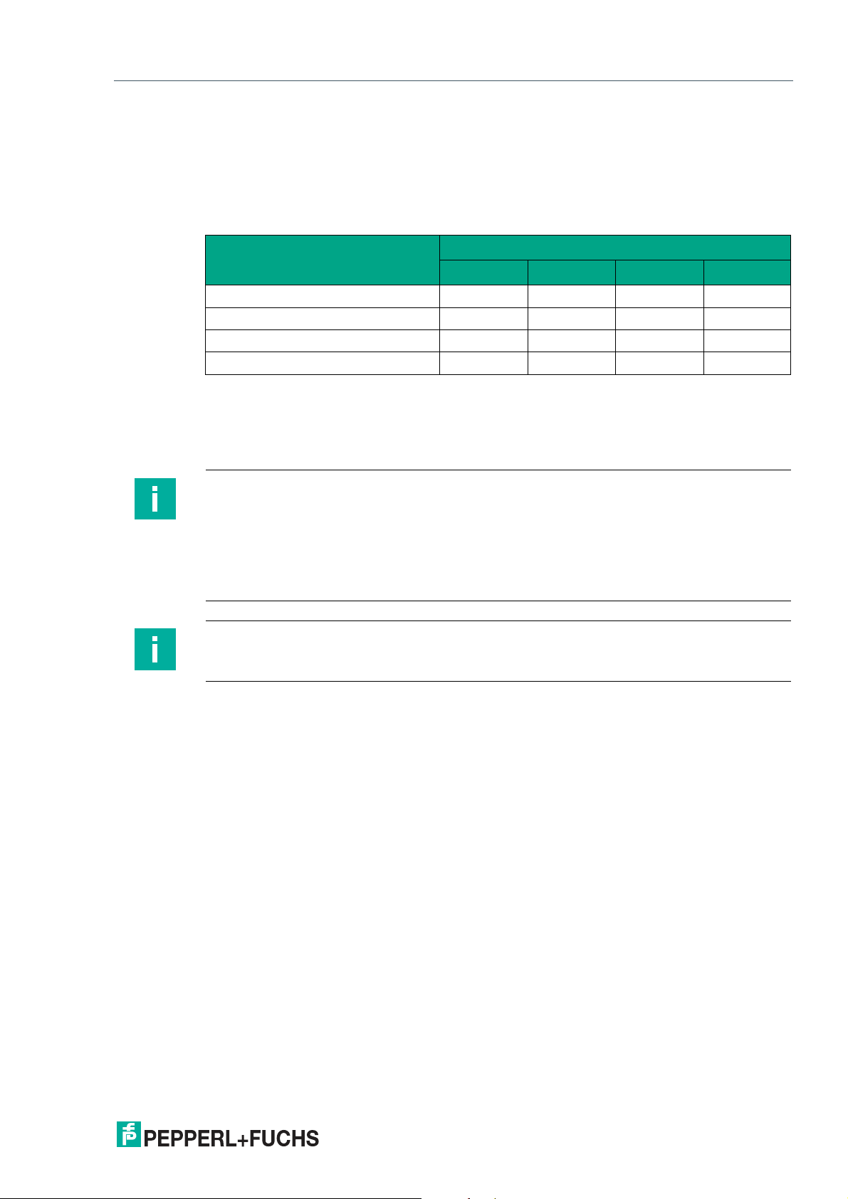
WCS* Read Head Position Encoding System
Options and Special Functions
9.4 Option-S—Velocity Output, Type LS...S
The WCS3B read head with velocity output features an additional 24 VDC output, which transmits a signal in the event that a limit speed is exceeded. The limit speed can be configured on
the 4-way DIP switch in the read head. The limit speed is set to 0.7 m/s on delivery.
Setting the limit speed (option -S only)
S1
Limit speed v
limit
0.7 m/s X X OFF OFF
2.0 m/s X X OFF ON
3.0 m/s X X ON OFF
4.0 m/s X X ON ON
The limit speed is output digitally via pin 5 of the 5-pin M12 connector:
Uv (pin 5) = operating voltage UB --> v
Uv (pin 5) = floating (high impedance) --> v
1 2 3 4
< v
current
current
limit
v
limit
Note
LED status indicator on the WCS3B read head with velocity output
The WCS3B read head has three LEDs on the front. The meaning of the yellow LED is
changed according to the speed setting.
Illuminated yellow: Limit speed not exceeded
Not illuminated yellow: Limit speed exceeded
Flashing red: Read head outside the code rail or read head dirty
Note
The set limit speed is not noted on the nameplate of the read head.
2020-01
69
Page 70
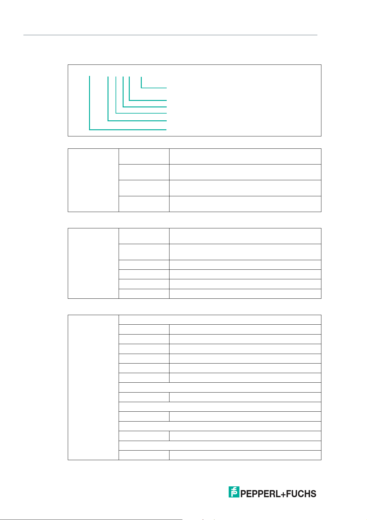
WCS* Read Head Position Encoding System
WCS.-LS . . . . .
-
Lesekopfadresse
Option(en)
Datenprotokoll
Baudrate
Hardware
Typ
Model Overview for WCS Read Heads
10 Model Overview for WCS Read Heads
Type 2B WCS2B read head (smaller enclosure, 1200 pos./m
with a maximum of 327 m)
3B WCS3B read head (1250 pos./m with a maximum of
314.573 m)
3R WCS3R read head (833 pos./m with a maximum of 39.3
m)
3T WCS3T read head (416 pos./m with a maximum of 78.6
m)
Hardware 1 Read head with RS-485 interface, no RS-485 termina-
tor
2 Read head with RS-485 interface, with RS-485 termina-
tor
3 Read head with SSI interface
4 Read head with CANopen interface
5 Read head with EtherNet/IP interface
6 Read head with PROFINET Interface
Baud rate Read head with RS-485 interface
1 187.50 kBaud
2 62.50 kBaud
3 31.25 kBaud
4 19.20 kBaud
5 9.60 kBaud
6 38.40 kBaud
Read head with SSI interface
1 100 kHz – 1000 kHz
Read head with CANopen interface
1 125 kBaud, 250 kBaud, 500 kBaud, 1 MBaud
Read head with EtherNet/IP interface
1 100 Mbit/s
Read head with PROFINET Interface
1 100 Mbit/s
70
2020-01
Page 71

WCS* Read Head Position Encoding System
Model Overview for WCS Read Heads
Data log Read head with RS-485 interface
1
6 Data log 3 with even parity (9 bit/byte)
7 Data log 3 without parity (8 bit/byte)
Read head with SSI interface
0 Data output in binary code
1 Data output in Gray code
Read head with a CANopen, EtherNet/IP, and PROFINET interface
0 Data output in binary code
1. Data log depends on read head request byte
Option D Read head with optional integrated display
E Read head with "Extended" option
H Read head with optional heating
S Read head with optional velocity output
OM Read head with "Outdoor" option (IP69K) and central
OL Read head with "Outdoor" option (IP69K) and left-hand-
OR Read head with "Outdoor" option (IP69K), and right-
Data log 1, data log 2
cable outlet
side cable outlet
hand-side cable outlet
1
Read head
address
Read head with RS-485 interface
0 Read head address 0
1 Read head address 1
2 Read head address 2
3 Read head address 3
- Read head address 0
2020-01
71
Page 72

WCS* Read Head Position Encoding System
Disposal
11 Disposal
The device, built-in components, packaging, and any batteries contained within must be disposed in compliance with the applicable laws and guidelines of the respective country.
72
2020-01
Page 73
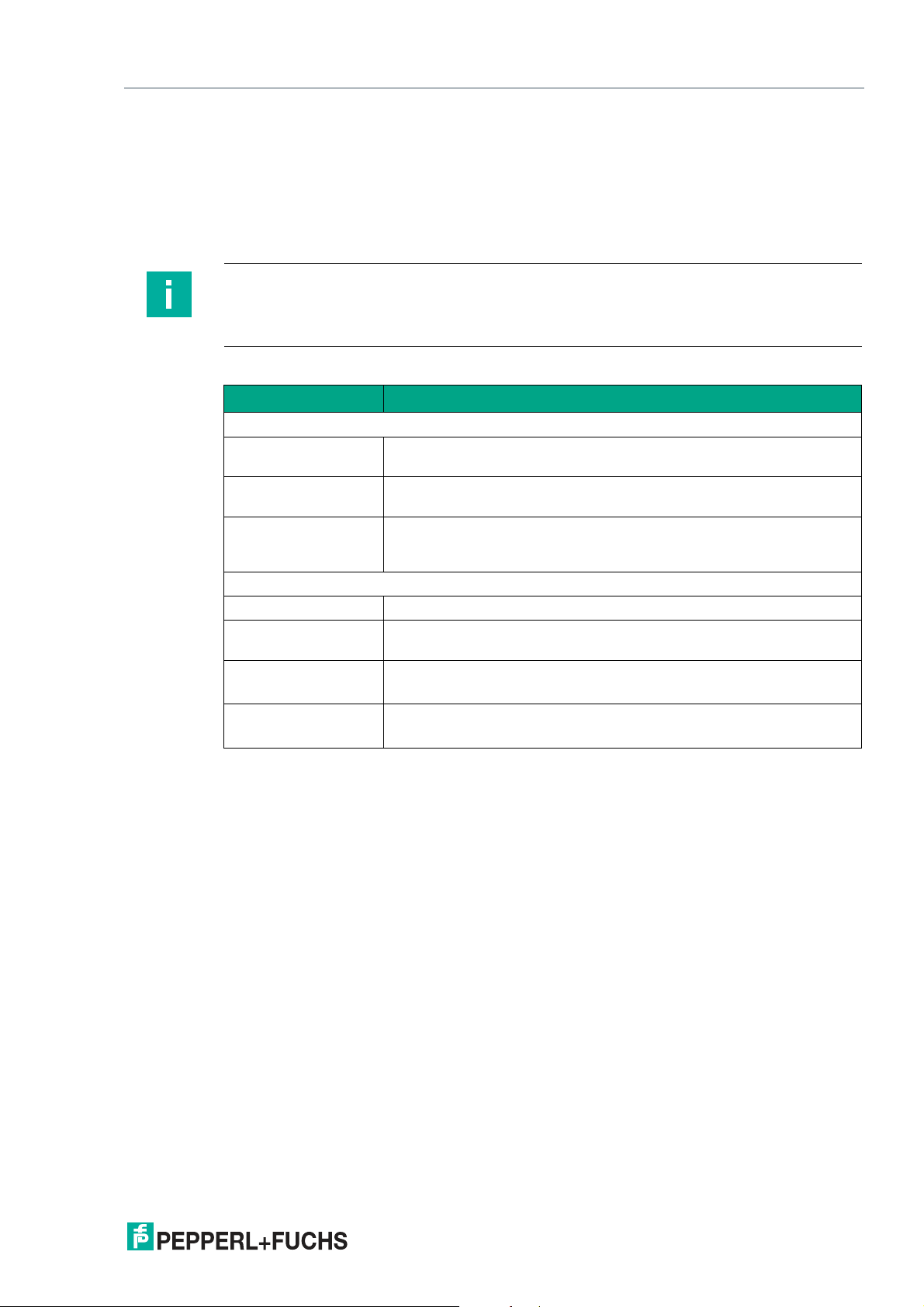
WCS* Read Head Position Encoding System
Appendix
12 Appendix
12.1 Cable Overview
The cable types listed below represent a selection of the types offered by Pepperl+Fuchs. Further cable types can be found on our website.
Note
For cables that you can assemble yourself, observe the cable length restrictions specified by
the interface specification. In the respective interface chapters you will find recommendations
for the maximum cable length.
RS-485 (LS1xx*, LS2xx*)
Cable Description
Pre-configured cable
V15-G-2M-PUR-ABG M12 single-ended female cordset, five-pins, straight, 2 m PUR cable,
V15-G-5M-PUR-ABG M12 single-ended female cordset, five-pins, straight, 5 m PUR cable,
V15-G-10M-PURABG
shielded,
shielded,
M12 single-ended female cordset, five-pins, straight, 10 m PUR cable,
shielded,
Configurable female cordset and meter goods
V15-G-ABG-PG9 Five-pin single-ended female cordset, field attachable, shielded
V15-G-ABG-PG9-FE Five-pin single-ended female cordset, field attachable, shielded with
grounding terminal
WCS-DCS
WCS-DCF
Available by the meter, six-pin data cable + shield, 0.14 mm
3 x 2 twisted wire pair
Available by the meter, six-pin data cable + shield, 0.25 mm
3 x 2 twisted wire pair, suitable for drag chains
2
2
2020-01
73
Page 74
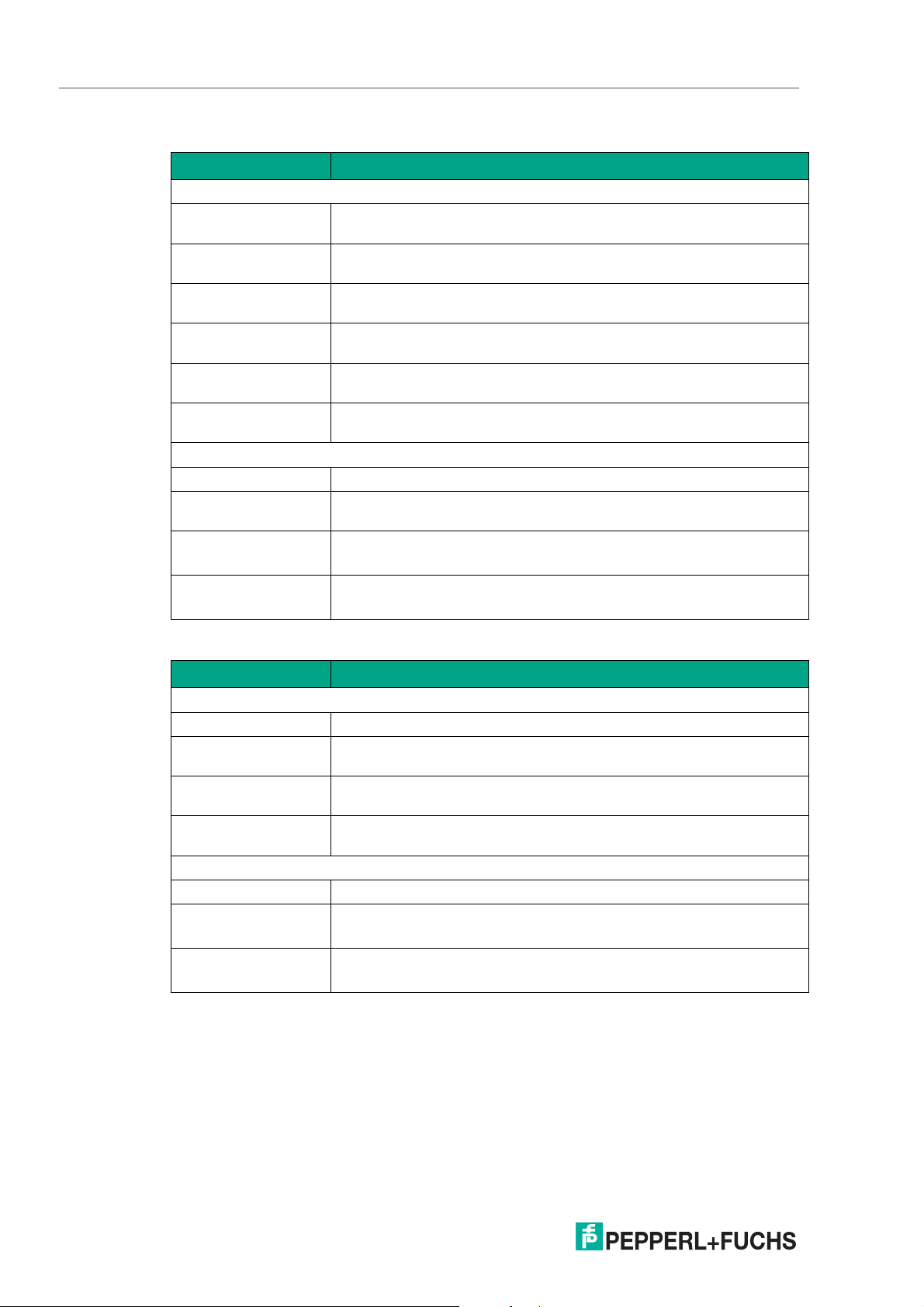
WCS* Read Head Position Encoding System
Appendix
SSI (LS3xx*)
Cable Description
Pre-configured cable
V19-G-2M-PUR-ABG M12 single-ended female cordset, eight-pin, straight, 2 m PUR cable,
V19-G-5M-PUR-ABG M12 single-ended female cordset, eight-pin, straight, 5 m PUR cable,
V19-G-10M-PURABG
V19-G-2M-PVC-TP Female cordset, M12, eight-pin, shielded, 2 m PVC cable
V19-G-5M-PVC-TP Female cordset, M12, eight-pin, shielded, 5 m PVC cable
V19-G-10M-PVC-TP Female cordset, M12, eight-pin, shielded, 10 m PVC cable
Configurable female cordset and meter goods
V19-G-ABG-PG9 Eight-pin single-ended female cordset, field attachable, shielded
V19-G-ABG-PG9-FE Eight-pin single-ended female cordset, field attachable, shielded with
WCS-DCS
WCS-DCF
shielded,
shielded,
M12 single-ended female cordset, eight-pin, straight, 10 m PUR
cable, shielded,
Shielded twisted pair
Shielded twisted pair
Shielded twisted pair
grounding terminal
Available by the meter, six-pin data cable + shield, 0.14 mm
3 x 2 twisted wire pair
Available by the meter, six-pin data cable + shield, 0.25 mm
3 x 2 twisted wire pair, suitable for drag chains
2
2
CANopen (LS4xx*)
Cable Description
Pre-configured cable
V15-G-2M-PUR-CAN CANopen bus cable, M12, 2 m PUR cable, five-pin
V15-G-2M-PUR-CAN-
CANopen bus cable, M12 to M12, 2 m PUR cable, five-pin
V15-G
V15-G-5M-PUR-CAN-
CANopen bus cable, M12 to M12, 5 m PUR cable, five-pin
V15-G
V15-G-10M-PUR-
CANopen bus cable, M12 to M12, 10 m PUR cable, five-pin
CAN-V15-G
Configurable female cordset and meter goods
V15-G-ABG-PG9-FE Female connector, M12, five-pin, shielded, field attachable
WCS-DCS
Available by the meter, six-pin data cable + shield, 0.14 mm
3 x 2 twisted wire pair
WCS-DCF
Available by the meter, six-pin data cable + shield, 0.25 mm
3 x 2 twisted wire pair, suitable for drag chains
2
2
74
2020-01
Page 75

WCS* Read Head Position Encoding System
Appendix
EtherNet/IP (LS5xx*) & PROFINET (LS6xx*)
Cable Description
Hybrid cable with common data line and supply voltage
V19SY-G-BK2MPUR-ABG
V19SY-G-BK5MPUR-ABG
V19SY-G-BK10MPUR-ABG
Y-splitter and cable (data cable and supply voltage separated)
V19SY-Y-V1D/V1S Y-splitter, M12 plug Y-coded to A-coded M12 plug/D-coded socket
V1SD-G-*M-PURABG-V45-G
1
V1-G-BK10M-PUR-U Single-ended female cordset, M12, four pins, PUR cable,
1. This cable type is available in various lengths 2 ... 45 m.
Single-ended male cordset, M12, 8-pin, Y coding, 2 m PUR cable,
shielded
Single-ended male cordset, M12, 8-pin, Y coding, 5 m PUR cable,
shielded
Single-ended male cordset, M12, 8-pin, Y coding, 10 m PUR cable,
shielded
Cordset, M12 to four-pin RJ-45 PUR cable, CAT5e,
in conjunction with Y-plug (data cable)
in conjunction with Y-plug (supply voltage)
2020-01
75
Page 76

Pepperl+Fuchs Qua lit y
Download our latest poli cy he re:
www.pepperl-fuchs.com/quali ty
© Pepperl+Fuchs · Subject to modifications
www.pepperl-fuchs.com
Printed in Germany / DOCT-5959A
 Loading...