

Page 1
RCWL301A Instruction Manual
A
Premium Portable Wirefree Chime with Push, Converter, and Door Contacts
Thank you for choosing this Honeywell product. Please use the following instructions
to ensure correct installation and use. Keep these notes in a safe place for future
reference.
Checking Pack Contents
Unpack your chime kit and identify the following parts:
• Chime (51360SL)
• Wall mounting bracket
• Bell push (51368SL)
• Bell push/converter/extender (51371SL)
• Door contacts
• 2x CR2032 battery for bell push and converter
• 4x mounting screws for door contacts
• 4x mounting screws for push/converter
• 2x mounting screws for chime
• 2x wall anchors
• 2x adhesive pads
• Bell wire (for use with converter and door contact)
• Self-adhesive icons
Y o u will need:
• 3x LR6 ‘AA’ Alkaline batteries
• Phillips screwdriver
• Small flat bladed screwdriver
• 1/4-in. (6 mm) masonry drill
Safety
Before proceeding with the installation, please note the following safety warnings:
• Always follow the manufacturer’s advice when using power tools and wear suitable
protective equipment (e.g. safety goggles) when drilling holes, etc.
• Before drilling holes in walls, check for hidden electricity cables and water pipes.
The use of a cable/pipe locator is advisable if in doubt.
• Batteries (battery pack or batteries installed) shall not be exposed to excessive heat
such as sunshine, fire or the like; danger of damage if battery is incorrectly
replaced. Replace only with the same or equivalent type.
Quick Start
The bell push and converter supplied with this kit are pre-programmed to operate with
the chime. You need to do the following to get started:
• Open the bell push and the converter
• Fit the push and converter batteries
• Fit the chime batteries
• Check the volume setting
When you operate the bell push and converter, the chime will sound and the icon will
flash.
T o use the door contacts, you need to wire them to the converter. Please refer to
steps in Wireless Converter/Ex te nd er/Push and Door Contact for setup.
If you use an additional push and converter or you want to assign a different
icon to your push, you will need to follow the Programming Procedure.
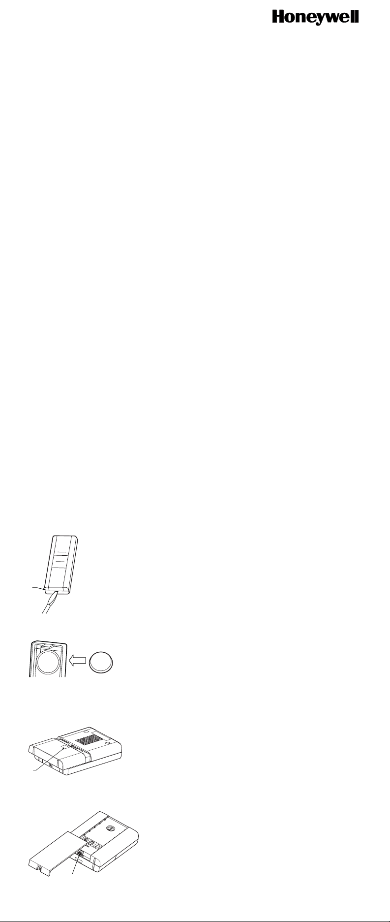
Open the Bell Push
Insert a flat bladed screwdriver into the slot A at the base of the push. Carefully lever
the cover and base apart (Fig. 1).
Fig. 1
M27199
Fit the Push Battery
Insert the CR2032 coin cell. Ensure the face marked ‘+’ is uppermost (Fig. 2).
CR
2
032
+
Fig. 2
CR2032
+
M27153
Fit the Chime Batteries
To remove the chime battery cover , press at point B and slide the cover back 1/4 in. (5
mm), then lift off. Insert 3 x LR6 ‘AA’ alkaline batteries (not supplied). Observe polarity
as marked inside the battery compartment (Fig 3).
B
Fig. 3
M27200
Sliding Window
Release the catch (B) and slide open the window (Fig. 4).
B
Fig. 4
69-2139EFS—03 1
M27201
Page 2
Installation instructions–RCWL301A
M27203
Fig. 7
Volume Control
The volume control is behind the sliding window on the front of the chime. Initially, set
the control to mid-point. After you have tested your system, adjust to the desired
volume (Fig. 5).
VOLUME CONTROL
Fig. 5
M27202
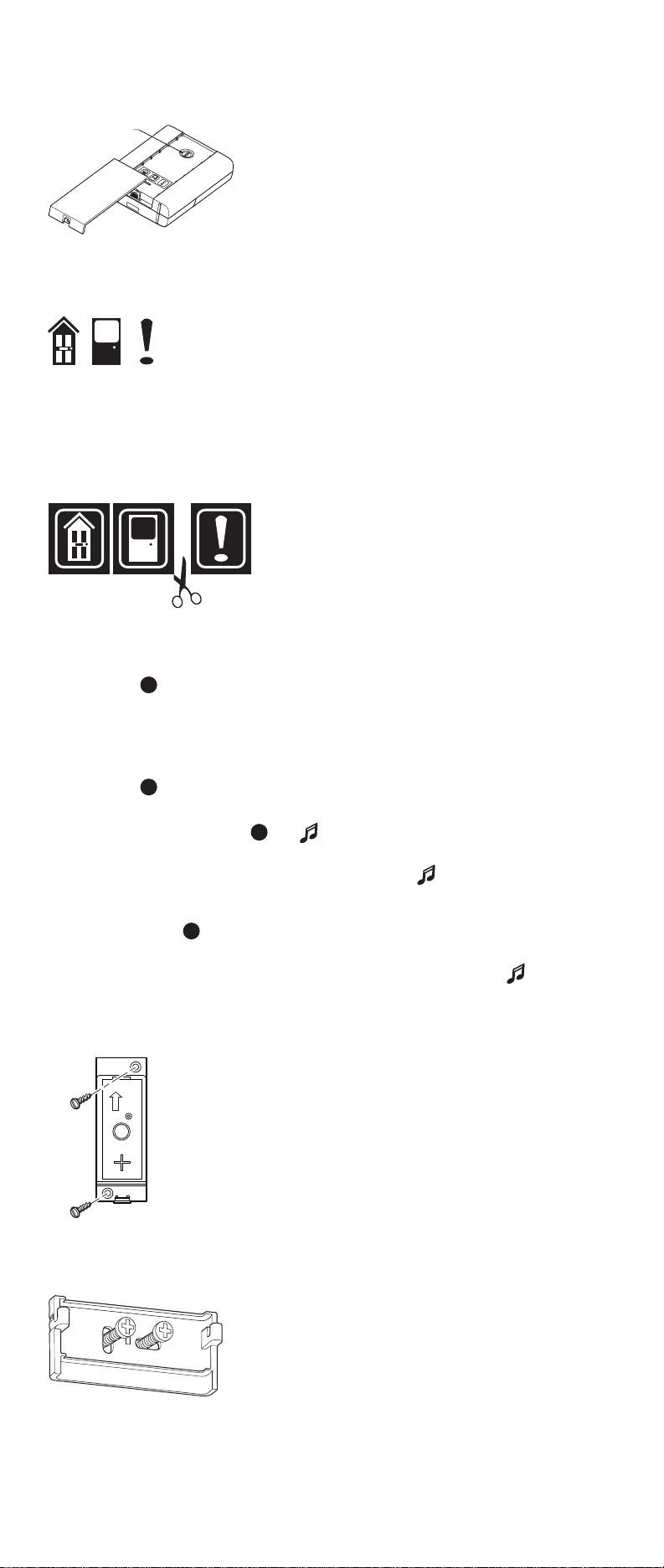
Use of Icons
In addition to the chime sounds, your chime has a visual indication to show which
device has activated it. An icon will illuminate when the chime is activated by the bell
push, the converter or another compatible device. The chime supports 3 icons.
MAIN
BACK
DOOR
ALERT
SYMBOL
DOOR
The ‘Main door’ and ‘Back door’ icons are usually used for bell pushes. The other icon
is intended for use with other compatible devices, such as the door contacts. Icons
numbered 1 to 3 are also included. The Icons are self-adhesive, supplied in strips of 3.
They can be changed, if required, by opening the sliding window of the chime and
gently peeling off the strips. If desired, the strips can be cut into individual icons and
attached to the chime in a different order. Use the Programming Procedure to change
the icon associated with a push.
Programming Procedure
Learn Procedure
To enable your chime to learn the identity of your transmitter:
• Press the button on top of the chime and keep it pressed. Each Icon will lig ht
in turn. When the Icon you want is lit, release the button.
• While the Icon you have selected is lit, operate your push. The chime will sound.
The Icon will flash.
Unlearn Procedure
If you want to remove a push from the chime’s memory:
• Press the button and keep it pressed.
• Each Icon will light in turn. When the Icon associated with the push to be unlearned
is lit, release the button.
• Press and hold down both & buttons, until a ‘beep’ sound is heard.
Changing the Tune
Operate the push. While the Icon is flashing, press the button. Press the button
again and the tune will change. Repeat until the tune you want plays.
Recall Function
A short push of the button will flash the Icon that was last in use.
Chime Sounds
To hear the chime sounds without operating the bell push, press the button.
Press the button again and the tune will change.
Mount the Push
Mount using either the double-sided adhesive pad or the screws provided. (See Fig.
6). Test your push before mounting. Avoid mounting to metal structures.
TOP
Fig. 6
M27155
Chime Position
The Chime can be free standing or wall mounted using the wall mounting bracket
provided. If wall mounting is preferred, screw the bracket to the wall (see Fig 7). The
Chime hooks onto the wall bracket as illustrated.
2 69-2139EFS—03
Page 3
Installation instructions–RCWL301A
Wireless Converter / Extender / Push and Door Contacts
The converter can be used as a standalone wireless push or as an interface for
door contacts.
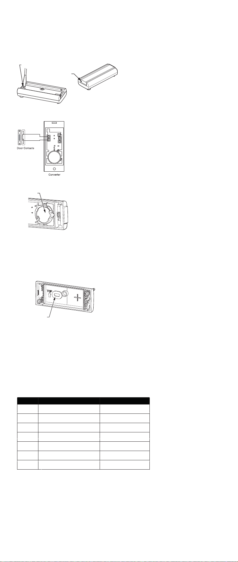
Open the bell push/converter
Using a ball point pen press at point A shown in fig 8. Remove the cover. Undo the
retaining screw B and remove the back of the push.
B
Fig. 8
A
Use the push/converter/extender with door contacts
Connect the push/converter/extender to the door contacts using the bell wire supplied.
Fit the Push/Converter/Extender Battery
Insert the CR2032 coin cell. Ensure the face marked ‘+’ is uppermost (Fig. 9).
CR2032CR2032
Fig. 9
When the door contacts (a normally closed circuit) are separated/opened, the
chime will make a fixed alert sound and the icon assigned to the converter will
flash.
Mount the door contacts to the door and door frame
Fix the push/converter/extender
Mount using either the double-sided adhesive pad or the screws provided. (See Fig.
10). Test your converter before mounting. Avoid mounting to metal structures.
Fig. 10
CABLE ENTRY GROMMET
M27168
Important note: Additional wiring can be brought into the push through the grommet in
the back of the push. Once the grommet has been pierced or removed, we
recommend that the push is mounted indoors.
Additional functions for Wireless Converter/Extender
It can be used to interface with an existing wired doorbell system or any of the
following:
• A standard wired bell push
• A lit bell push and transformer
• A door or window contact
• Any device with N/O or N/C, voltage free contacts
• Any device which generates appropriate control signal
< 24V (AC or DC)
See typical connections (C1-7)
Diagram Application Operation
C1
C2
C3
C4
C5
C6
C7
wired bell push or 'normally
open' switch/contacts
door/window contact, 'normally
closed' switch/contacts
a lit push (with transformer) when
switch is closed, chime will sound
landscape push/converter terminal positions
a typical wired bell or chime circuit transformer powered
converter connected to a wired bell
or chime -transformer powered
converter connected to a wired bell
or chime circuit - battery powered
when switch is closed,
chime will sound
when switch is opened, chime
will make a fixed 'ALERT' sound
when switch is closed,
chime will sound
when push is operated,
chime will sound
when push is operated,
chime will sound
3 69-2139EFS—03
Page 4

Installation instructions–RCWL301A
~
1
2
3
4
5
1
2
3
4
5
BELL
120V
~
(5 activations/day)
C3
C4
For C7 connection: Connect converter terminal 3
to the negative (-) terminal of the batteries in the
wired chime and converter terminal 1 to the
1
2
3
4
5
1
5
4
positive (+) terminal of the batteries in the wired
2
3
chime.
For C5 and C6 connections: Turn off power
before connecting converter to transformer.
C6 C7
BELL
(T1-T5)
120V
12 months 18 months 18 months
N/A 24V (AC or DC) N/A
BELL
+–
1
2
3
4
5
1
2
3
4
5
Bell Push/
Converter/Extender
14°F to 104°F (-10ºC to 40ºC) 14°F to 104°F (-10ºC to 40ºC)
BellPush
Typical Connection
C1
C2
C5
Specification Chime
Operating Temperature 32°F to 104°F (0ºC to 40ºC)
RF Frequency US/Canada 916.8 MHz 916.8 MHz 916.8 MHz
Range (open field) 225 ft. (69 m) See Chime See Chime
Sound Level (typical) 80dBA @ 3 ft. (1m) - -
RF Power - < 1mW <1mW
Battery Type LR6 CR2032 CR2032
Battery Life
Rain proof N/A Pass UL rain test. Pass UL rain test.
Maximum input voltage
Troubleshooting
A ‘beep’ sound is heard in learn mode…
• The push you are programming has already been learned by the chime.
• If you want to change the Icon associated with the push, use the un-learn
procedure, then program the push again.
Two ‘beep’ sounds are heard after the normal chime sound…
• This indicates a low battery in the bell push that activated the chime. Fit a new
battery, type CR2032.
When the bell push is operated, the amber confidence light does not turn on, or
is only on for a short time…
• In normal operation, the amber light will turn on for 1 second. When the battery is
weak, the light will only turn on for a short time. Fit a new battery, type CR2032.
The chime does not work…
• Check that the batteries are the correct type, LR6 ‘AA’ cells. Only use alkaline
batteries.
• Check that the batteries are fitted correctly, with correct polarity.
• The chime could be out of range of the bell push. Try the chime in a different
location.
• The chime might not have learned the identity of the bell push. Follow the
programming procedure.
The chime does not sound…
• Check that the volume control is not at the minimum setting.
Range is reduced…
• Metal structures, including uPVC door frames can reduce the range of the product.
Avoid mounting the push or chime on or near metal structures.
• Other equipment can cause radio interference that affects your chime.
• Walls and ceilings will reduce the range.
• Weak batteries will reduce range. Replace every 12–18 months. In cold conditions
(below 41ºF [5ºC]), batteries may need to be replaced more often.
Amber light flashes…
• When the chime battery is low, an amber light will flash every 5 seconds. Fit new
batteries in the chime, type LR6 ‘AA’ cells. Only use alkaline batteries.
When the push converter function is used with the door contacts, the chime
does not operate...
• Ensure that the wiring to the push is correct.
• Check that the correct terminals have been used and the screws are tightened.
Disposal & Recycling
Batteries and waste electrical products should not be disposed of with household
waste. Please recycle where these facilities exist. Check with your local authority or
retailer for recycling advice.
Declaration
Honeywell hereby declares that this product complies with Part 15 of the FCC rules
and Industrial Canada standards.
This device operation is subject to the following two conditions:
(1) This device may not cause harmful interfere n c e , an d
(2) This device must accept any interference received, including interference that may
cause undesired operation.
Caution: Changes or modification not expressly approved by the party responsible for
regulatory compliance could void the user’s authority to operate the equi pment.
Guarantee
Honeywell guarantees this product for 1 year from the date of purchase. Proof of
purchase is required: this does not affect your statutory rights. If you require further
information about your product call the Honeywell help line at 1-800-468-1502.
4 69-2139EFS—03
Page 5

Installation instructions–RCWL301A
A
RCWL301A Manual de instrucciones
Campanilla sin cables portátil de primera con pulsador, convertidor, y contactos
para puerta
Gracias por elegir este producto Honeywell. Por favor utilice las siguientes
instrucciones para lograr la instalaciéon y uso adecuados del producto. Conserve
estas notas en un lugar seguro para referencia futura.
Verificación del contenido del empaque
Desempaque su kit de campanilla e identifique las siguientes partes:
• Campanilla (51360SL)
• Soporte para montaje en pared
• Pulsador del timbre (51368SL)
• Pulsador del timbre/convertidor/extensor (51371SL)
• Contactos para puerta
• 2 baterías CR2032 para pulsador del timbre y convertidor
• 4 tornillos de fijación para contactos para puerta
• 4 tornillos de fijación para pulsador del timbre/convertidor
• 2 tornillos de fijación para campanilla
• 2 tarugos de pared
• 2 almohadillas adhesivas
• Cable del timbre (para usar con convertidor y contacto para puerta)
• Iconos autoadhesivos
Necesitará:
• 3 baterías alcalinas LR6 ‘AA’
• Un destornillador Phillips
• Destornillador pequeño de hoja plana
• Un taladro de 6 mm para mampostería
Seguridad
Antes de proceder con la instalación, por favor observe las siguientes advertencias
sobre seguridad:
• Siempre siga las recomendaciones del fabricante cuando utilice herramientas
eléctricas y utilice equipo protector adecuado (por ej.: gafas de seguridad) cuando
taladre agujeros, etc.
• Antes de taladrar agujeros en las paredes, revise si existen cables de electricidad o
tuberías de agua ocultos. El uso de un localizador de cables/tuberías puede ser
aconsejable si tiene dudas.
• Las baterías (el paquete de baterías o las baterías instaladas) no deben exponerse
al calor excesivo tal como el de la luz solar, el fuego o semejante; Peligro de daños
si la batería se reemplaza incorrectamente. Reemplazo sólo con el mismo tipo u
otro equivalente.
Arranque rápido
El pulsador de timbre y el convertidor que se suministra con este kit están
preprogramado para operar con la campanilla. Para comenzar debe hacer lo
siguiente:
• Abra el pulsador del timbre y el convertidor.
• Coloque las baterías del pulsador y el convertidor.
• Coloque las baterías de la campanilla.
• Revise la regulación del volumen.
Cuando accione el pulsador del timbre y el convertidor, la campanilla sonará y el
icono destellará.
Para utilizar los contactos de la puerta, necesita cablearlos al convertidor.
Refiérase a los pasos en Convertidor/Extensor/Pulsador inalámbrico y el
Contacto de la puert a para la configuración.
Si tiene un pulsador adicional y un convertidor, o desea asignar un icono
diferente a su pulsador, deberá seguir el Procedimiento de programación.
Abra el pulsador del timbre
Inserte un destornillador de hoja plana en la ranura A en la base del pulsador.
Cuidadosamente apalanque la cubierta y la base para separarlas (Fig. 1).
Fig. 1
M27199
Para colocar la batería del pulsador
Inserte la pila tipo botón CR2032. Revise que la parte marcada ‘+’ esté en la parte
superior (Fig. 2).
CR
2
032
+
Fig. 2
CR2032
+
M27153
Coloque las baterías de la campanilla
Para retirar la cubierta de la batería de la campanilla, presione en el punto B y deslice
la cubierta 5 mm hacia atrás, luego levante. Inserte 3 baterías alca linas LR6 ‘AA’ (no
incluidas). Observe la polaridad según se marca dentro del compartimiento para
baterías (Fig. 3).
B
Fig. 3
M27200
5 69-2139EFS—03
Page 6

Installation instructions–RCWL301A
Ventanilla deslizante
Libere el enganche (B) y deslice la ventanilla para abrirla (Fig. 4).
B
M27201
Fig. 4
Control de volumen
El control de volumen está detrás de la ventanilla deslizante al frente de la campanilla.
Inicialmente, coloque el control a la mitad. Después de probar su sistema, regúlelo al
volumen deseado (Fig. 5).
CONTROL DE VOLUMEN
Fig. 5
M27202
Uso de los iconos
Además de los sonidos de la campanilla, la misma tiene una indicación visual para
mostrar el dispositivo que la ha activado. Un icono se iluminará cuando la campanilla
se haya activado por medio de un pulsador de timbre, un convertidor u otro dispositivo
compatible. La campanilla soporte 3 iconos.
PUERTA
PUERTA
TRASERA
SIMBOLO
DE ALERTA
PRINCIPAL
Los iconos de ‘Puerta principal’ y ‘Puerta trasera’ se utilizan generalmente para
pulsadores de timbre. El otro icono está destinado para uso con otros dispositivos
compatibles, tales como los contactos de puerta. Los iconos numerados del 1 al 3
también están incluidos. Los iconos son autoadhesivos, y se suministran en bandas
de 3. Se pueden cambiar, si fuese necesario, abriendo la ventanilla deslizante de la
campanilla y desprendiendo suavemente las bandas. Si lo desea, las bandas pueden
cortarse en iconos individuales y fijarse a la campanilla en un orden diferente.
Utilice el Procedimiento de programación para cambiar el icono asociado con un
pulsador.
Procedimiento de programación
Procedimiento de memorización
Para posibilitar que su campanilla aprenda la identidad de su transmisor:
• Presione el botón en la parte superior de la campanilla y manténgalo
oprimido. Cada icono se iluminará uno por uno. Cuando el icono que desea se
ilumine, suelte el botón.
• Mientras esté iluminado el icono que ha seleccionado, accione su pulsador. La
campanilla sonará. El icono destellará.
Procedimiento de desprogramación
Si desea retirar un pulsador de la memoria de la campanilla:
• Presione el botón y manténgalo oprimido.
• Cada icono se iluminará uno por uno. Cuando el icono asociado con el pulsador
que desea desprogramar se ilumina, suelte el botón.
• Presione y sostenga tanto el botón como el botón hasta que se escuche
sonar el “tono”.
Cambio de la melodía
Accione el pulsador. Mientras el icono esté destellando, presione el botón .
Presione el botón nuevamente y la melodía cambiará. Repita hasta que suene la
melodía que desea escuchar.
Función de memoria
Una presión breve del botón hará destellar el último icono que se utilizó.
Sonidos de la campanilla
Para escuchar los sonidos de la campanilla sin accionar el pulsador del timbre,
presione el botón . Presione el botón nuevamente y la melodía cambiará.
Montaje del pulsador.
Colóquelo utilizando la almohadilla adhesiva de doble lado o los
tornillos que se proporcionan. (Fig. 6 ). Pruebe el pulsador antes de
TOP
fijarlo. Evite fijarlo a estructuras metálicas
Posición de la campanilla
Fig. 6
La campanilla puede estar independiente o montada en pared
utilizando el soporte para montaje en pared que se suministra. Si se
elige el montaje en pared, atornille el soporte a la pared (Fig. 7). La
campanilla se engancha al soporte de pared como se ilustra.
M27155
Fig. 7
M27203
Convertidor/extensor/pulsador inalámbrico y co ntactos para puerta
El convertidor puede utilizarse como pulsador inalámbrico independiente o como
interfaz para contactos de puerta.
6 69-2139EFS—03
Page 7

Installation instructions–RCWL301A
~
Abra el pulsador/convertidor del timbre
Con un bolígrafo, presione en el punto A, tal como se muestra en la fig. 8. Quite la
cubierta. Retire el tornillo de retención B y quite la parte posterior del pulsador.
B
A
Fig. 8
Utilice el pulsador/convertidor/extensor con los contactos de puerta
Conecte el pulsador/convertidor/extensor a los contactos de puerta utilizando el cable
para timbre que se suministra.
Para instalar la batería del pulsador/convertidor
Inserte la pila tipo botón CR2032. Revise que la parte marcada ‘+’ esté en la parte
superior (Fig. 9).
CR2032CR2032
Fig. 9
Cuando los contactos de la puerta (generalmente un circuito cerrado) se
separan/abren, la campanilla emitirá un sonido de ‘ALERTA’ fijo y el icono
asignado al convertidor destella.
Fije los contactos de la puerta a la puerta y al marco.
Instalación del pulsador/convertidor/extensor
Colóquelo utilizando la almohadilla adhesiva de doble lado o los tornillos que se
proporcionan (Fig. 10). Pruebe el pulsador antes de fijarlo. Evite fijarlo a estructuras
metálicas.
Fig. 10
ARANDELA AISLANTE
DE ACCESO DEL CABLE
M27168
Nota importante: Se puede traer más cable hacia el pulsador a través de la arandela
aislante ubicada en la parte posterior del pulsador. Una vez que la arandela aislante
haya sido perforada o retirada, le recomendamos que instale el pulsador en interiores.
Funciones adicionales para el convertidor/extensor inalámbrico
Puede usarse para conectarlo a un sistema cableado existente de timbres para
puertas o con cualquiera de los siguientes dispositivos:
• un pulsador del timbre cableado estándar
• un transformador y pulsador del timbre iluminado
• un contacto de puerta o ventanacualquier dispositivo con contactos sin voltaje N/O
o N/C
• cualquier dispositivo que genere señales de control adecuadas < 24V (AC o DC).
Vea las conexiones típicas (C1-7).
C2 se utiliza para los contactos para puerta/ventana incluidos
Diagrama
C1
C2
C3
C4
C5
C6
C7
Aplicación Funcionamiento
pulsador del timbre cableado o contactos/interruptor ‘normalmente abiertos’
contacto de puerta/ventana, contactos/interruptor ‘normalmente cerrados’
un pulsador iluminado (con transformador) cuando
el interruptor esté cerrado, la campanilla sonará
pulsador/convertidor horizontal;
posiciones de las terminales
un timbre cableado típico o circuito de la
campanilla - funciona con transformador
convertidor conectado a un timbre cableado
o a una campanilla -funciona con transformador
convertidor conectado a un timbre cableado o a
un circuito de la campanilla - funciona a batería
cuando el interruptor esté cerrado,
la campanilla sonará
cuando el interruptor esté abierto, la campanilla emitirá un sonido de ‘ALERTA’ fijo
cuando el interruptor esté
cerrado, la campanilla sonará
cuando se accione el pulsador,
la campanilla sonará
cuando se accione el pulsador,
la campanilla sonará
120V
~
C3
1
2
3
4
5
1
2
3
4
5
C6 C7
TIMBRE
Conexión promedio
C1
C2
C5
TIMBRE
120V
C4
Para la conexión C7: Conecte el terminal
convertidor 3 al terminal negativo (-) de las
baterías en la campanilla cableada y el terminal
1
2
3
4
5
1
5
4
convertidor 1 al terminal positivo (+) de las
2
3
baterías en la campanilla cableada.
Para las conexiones C5 y C6: Desconecte la
energía antes de conectar el convertidor al
transformador.
TIMBRE
+–
1
2
3
4
5
1
2
3
4
5
7 69-2139EFS—03
Page 8

Installation instructions–RCWL301A
Especificación Campanilla
Temperatura de funcionamiento
Frecuencia RF-EE.UU./Canadá
Alcance (campo abierto) 225 pies (69 m) Ver campanilla Ver campanilla
Nivel de sonido (promedio) 80dBA @ 3 pies (1m) - -
Potencia RF - < 1mW <1mW
Tipo de batería LR6 CR2032 CR2032
Vida de la batería (5 activaciones por día)
A prueba de lluvia N/A Pasa la prueba de lluvia. Pasa la prueba de lluvia.
Voltaje de entrada máximo (T1-T5)
32°F a 104°F (0ºC a 40ºC) 14°F a 104°F (-10ºC a 40ºC) 14°F a 104°F (-10ºC a 40ºC)
916.8 MHz 916.8 MHz 916.8 MHz
12 meses 18 meses 18 meses
N/A 24V (AC o DC) N/A
Pulsador del timbre/
Convertidor/Extensor
Pulsador del timbre
Localización y solución de problemas
Se escucha un “tono” en la modalidad de memorización...
• El pulsador que está programando ya ha sido programado por la campanilla.
• Si desea cambiar el icono relacionado con el pulsador, utilice el procedimiento de
desprogramación, luego programe el pulsador nuevamente.
Se escuchan dos “tonos” después del sonido normal de la campanilla…
• Esto indica que la batería del pulsador del timbre que activa la campanilla está
baja. Coloque una nueva batería tipo CR2032.
Cuando se acciona el pulsador del timbre, la luz ámbar de confirmación no se
enciende, o se enciende únicamente por poco tiempo...
• En condiciones normales de funcionamiento, la luz ámbar se encenderá durante 1
segundo. Cuando la batería está débil, la luz se encenderá únicamente por poco
tiempo. Coloque una nueva batería tipo CR2032.
La campanilla no funciona...
• Verifique que las baterías sean del tipo adecuado, LR6 ‘AA’ Use baterías alcalinas
únicamente.
• Verifique que las baterías estén colocadas adecuadamente. (que la polaridad no
sea incorrecta).
• La campanilla podría estar fuera del área de alcance del pulsador del timbre.
Pruebe la campanilla en un lugar diferente.
• La campanilla podría no haber memorizado la identidad del pulsador del timbre.
Siga el procedimiento de programación.
La campanilla no suena...
• Verifique que el control de volumen no esté en la posición mínima.
Se ha reducido el alcance...
• Las estructuras metálicas, incluyendo los marcos de puerta uPVC pueden
disminuir el alcance del producto. Evite colocar el pulsador or la campanilla sobre o
cerca de objetos metálicos.
• Otros equipos pueden ocasionar interferencia de radio que afecte su campanilla.
• Las paredes y los techos disminuyen el alcance.
• Las baterías con poca carga disminuyen el alcance. Cambie cada 12 – 18 meses.
En temperaturas frías (inferiores a 5ºC), las baterías podrían necesitar
reemplazarse con mayor frecuencia.
La luz ámbar destella...
• Cuando la batería de la campanilla está baja, una luz ámbar destellará cada 5
segundos. Coloque nuevas baterías en la campanilla, tipo LR6 ‘AA’. Use baterías
alcalinas únicamente.
Cuando la función del convertidor pulsador se utiliza con los contactos de
puerta, la campanilla no funciona...
• Asegúrese de que el cableado al pulsador haya sido efectuado de forma correcta.
• Verifique que los terminales adecuados hayan sido utilizados y los tornillos estén
apretados.
Desecho y reciclaje
Las baterías y los desechos procedentes de productos eléctricos no deben colocarse
con los desechos domésticos. Por favor recicle donde haya tales instalaciones.
Verifique con las autoridades locales o el distribuidor la disponibilidad del servicio de
reciclaje.
Declaración
Honeywell por la presente declara que este producto cumple con la Parte 15 de las
regulaciones FCC y las normas industriales de Canadá. El funcionamiento de este
dispositivo está sujeto a las siguientes dos condiciones: (1) Este dispositivo no debe
causar interferencia perjudicial, y (2) Este dispositivo deberá aceptar cualquier
interferencia que se reciba, incluyendo la interferencia que pudiese causar el
funcionamiento no deseado.
Precaución: Los cambios o modificaciones que no hayan sido expresamente
aprobados por la parte responsable del acatamiento a las regulaciones podrían anular
la autoridad del usuario para operar el equipo.
Garantía
Honeywell garantiza este producto por el lapso de 1 año a partir de la fecha de
compra. La prueba de compra es necesaria; esto no afecta sus derechos legales. Si
necesita mayor información sobre su producto, llame a la línea de ayuda de
Honeywell al 1-800-468-1502.
Automation and Control Solutions
Honeywell International Inc.
1985 Douglas Drive North
Golden Valley, MN 55422
yourhome.honeywell.com
® U.S. Registered Trademark
© 2008 Honeywell International Inc.
69-2139EFS—03 P.B. Rev. 10-08
69-2139EFS-03
 Loading...