

Page 1

Page 2

2
G6
User Manual
TI Asahi Co.,Ltd
Version 1.0
Page 3

3
Content
Chapter1 Brief introduction
........................................................................................................
4
1.1 Key Features
...............................................................................................................
4
1.2 G6 Receiver
.................................................................................................................
6
1.2.1. Front side of the Receiver
....................................................................................
6
1.2.2. Back side of the Receiver
.....................................................................................
8
1.2.3. The bottom of Receiver
.......................................................................................
8
Chapter2 Basic operations of G6
..............................................................................................
10
2.1 The installation of base and rover
............................................................................
10
2.2 The operation of keys
...............................................................................................
11
2.3 Self-checking
.............................................................................................................
11
2.4 Measure the antenna height
....................................................................................
12
Chapter3 Web UI function
........................................................................................................
21
3.1 Status
........................................................................................................................
22
3.2 Information
...............................................................................................................
22
3.3 Download
..................................................................................................................
23
3.4 Management
............................................................................................................
23
3.4.1 Device register
...................................................................................................
24
3.5 Settings
.....................................................................................................................
25
3.5.1. Working mode
...................................................................................................
25
3.5.2. Device configuration
..........................................................................................
30
3.5.3. NMEA Message
..................................................................................................
31
Chapter4 G6 standard accessories
...........................................................................................
32
4.1 The case of G6
...........................................................................................................
32
4.2 Power supply
............................................................................................................
32
4.3 The antennas
............................................................................................................
32
4.4 Other accessories
......................................................................................................
33
Chapter5 Appendixes
...............................................................................
错误!未定义书签。
Appendix 1 Default radio configuration
..........................................................................
34
Appendix 2 Voice messages
.............................................................
错误!未定义书签。
Appendix 3 Specification
..................................................................................................
35
Page 4

4
Chapter1 Brief introduction
This chapter is mainly used to introduce the key features and the appearance of G6.
As the latest generation of GNSS receiver, G6 brings you a better user experience.
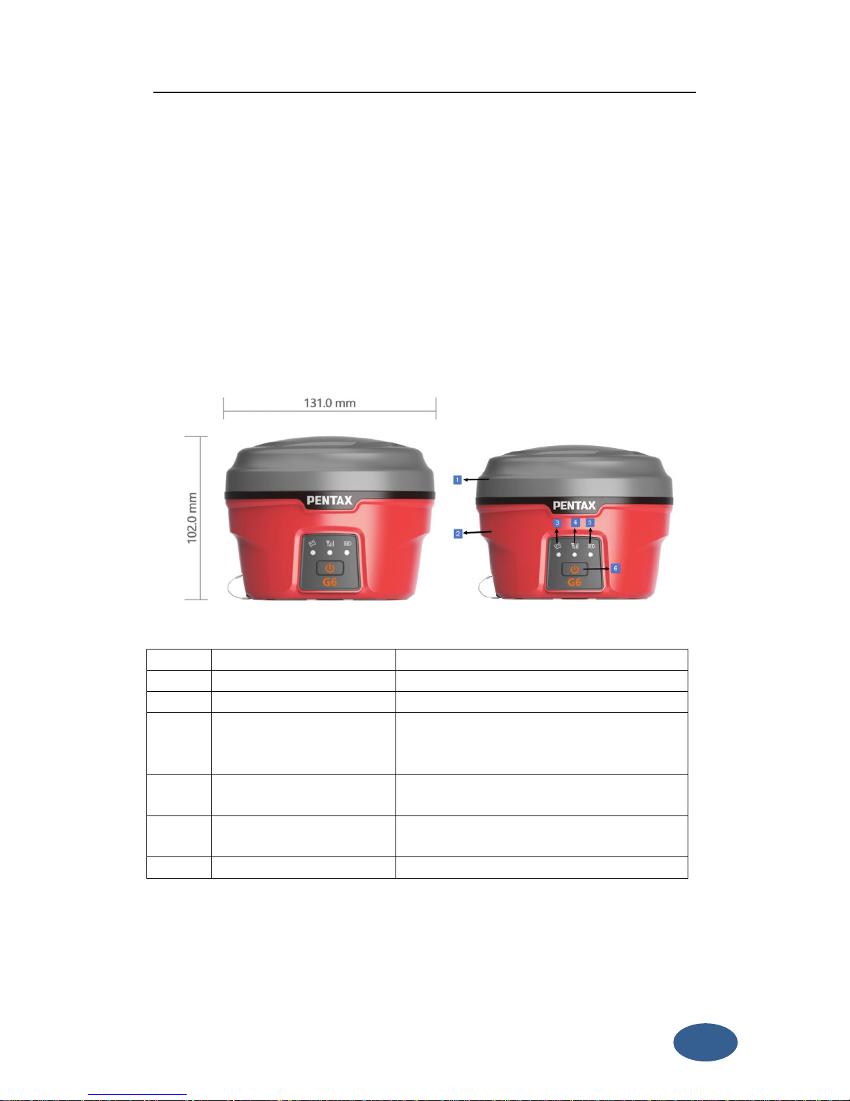
The dimension and weight also has a great breakthrough, now the dimension is
diameter 131mm × height 102mm, the weight is just 1kg (with battery). Adopt many
new technologies, there are some functions add to G6 and this make survey work
more convenient.
1.1 Key Features
Designed and developed by a group of excellent developers, G6 has many technical
innovation. All of the innovation can help you finish the survey work quickly and high
efficiently. They can be summarized in 5 points, as follow:
(1) Electric bubble
G6 has electronic bubble technology, bubble is appeared on the controller
display screen. Thanks to the new electronic bubble, all measurement
information will be displayed in one place. And when you check whether the
support pole is leveling, you don’t need to use the physical bubble in the
support hole to level.
(2) WIFI wireless connection
When the WIFI function is opened, G6 can be used as a hotspot. You can
connect your phone to it via WIFI. Log on the WEB UI, then you can do many
configurations with your phone, such as change work mode, change datalink,
download static data.
(3) Dual mode Bluetooth
G6 supports 4.0 long-distance Bluetooth and can connect to mainstream
mobile phone, pad and digital consume products. Meanwhile can be
compatible with Bluetooth 2.1 and connected with industrial-grade
controller.
(4) Double backup of the survey data
Page 5

5
G6 RTK survey data will have double back-up, by controller and receiver so as
to make sure the survey data is safe and reliable.
(5) Compatible with all satellite constellations
Not only can track all of the current satellite systems, but also can support
the satellites in planned. The excellent performance in tracking satellites
make it easily cope with and face to future.
Besides the latest technical innovation, there are also development in the hardware
and accessories, such as the battery and some useful tools. All of these make sure
our users grasp the most advantaged thing in use.
(1) Compact and lightweight design.
The dimensions of G6 is radius 131mm × height 102mm, but its weight is just
1kg (with battery). The compact and lightweight design allow users to carry
out easily.
(2) Advanced datalink
The radio module and the communication protocol are compatible with the
main RTK products in the market and able to work together with other brand
RTK products so as to optimize your asset allocation. The 3.75G modules
support WCDMA, GPRS and other networks. It can continuously and stably
work with CORS.
(3) Innovation double high-capacity batteries
The double batteries design ensures the long worktime.
(4) 50HZ high-speed acquisition
With powerful intelligence platform, G6 supports maximum 50HZ high rate
data acquisition so as to be convenient for taking expansion of high dynamic
survey.
(5) Large capacity storage
Configure with 4GB internal memory, G6 can store a large amount of survey
data. It also supports storage expansion, the maximum32GB micro SD card.
All of the innovation and advantage in using can give a high efficiency survey
experience. We always do our best to support the best equipment and technical
Page 6
6
service to the customers.
1.2 G6 Receiver
G6 receiver is a flat cylindrical, 102mm in height, 131mm in diameter. The front side
has 1 power buttons and 3 indicators. The back side is a battery compartment. In the
compartment, there are two slots, one for SIM card another for Micro SD card.
The bottom of the receiver is some interfaces. They include a radio antenna interface,
a 5 pin external power interface and a 7 pin RS232/USB interface.
1.2.1. Front side of the Receiver
Figure 1- 1 Front panel
Number
Name
Function
1
Top housing
Protect the antenna.
2
Lower housing
Protect the receiver in case of drop.
3
Satellite led
How many time it blinks, means how many
satellites are locked, cycle once every 5
seconds.
4
Network led
It will blink when G6 is transmitting differential
data.
5
Power led
After the G6 turn on, the led always light and
indicate the remaining power.
6
Power key
Power on/off the receiver.
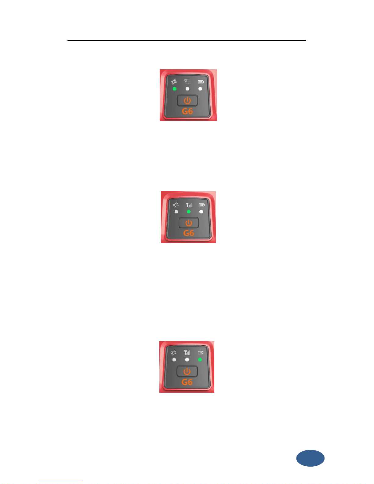
Satellite led (green)
It shows the amount of locked satellites; when the receiver links one or more
satellites signal it will start to blink every 30 seconds for a number of times equal to
Page 7
7
the number of locked satellites. When the receiver doesn’t lock satellites, the
satellite led does not shine.
Figure 1- 2 Satellite led
Network led (green)
This light is on when GSM/GPRS module is selected as RTK datalink. It starts to
blink when there is data transfer ongoing (In both radio, Bluetooth and network
data link mode, it will blink when there is data transfer ongoing).
Figure 1- 3 Network led
power led (green and red)
When you power on the G6, the power led will be on. According to the remaining
power of the battery, it includes two kinds of status:
1. Green: power supply in good condition.
2. Red: power is less than 10%(when the total power of two batteries is less
than 10%,the power led is red),and you will hear three beeps every 60s.
Figure 1-4 Power led
Note: Usually when the light is red you have still half an hour of power reserve.
External power and internal battery share same power light. When external power is
Page 8
8
used, the led indicates the external power level.
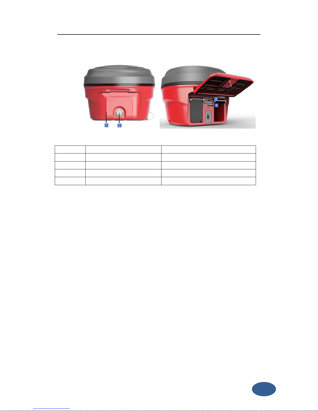
1.2.2. Back side of the Receiver
Figure 1- 5 G6 back side
Number
Name
Function
1
Battery compartment cover
Protect the battery
2
Compartment locker
Open/lock the cover
3
Micro SD card slot
Put and read Micro SD card
4
SIM card slot
Put and read SIM card
Installing/Uninstalling SIM card and microSD card
There is a SIM card slot and a micro SD card slot in the middle of the two battery
houses, the upper one is SIM card slot. To install the SIM card, just push the SIM card
into the SIM card slot according to the prompting figure. The microSD card
installation is similar to the SIM card installation.
To remove the SIM card and microSD card, push the card and then take out the card.
Note: When you select network mode to work, you need to install SIM card.
Installing/Uninstalling battery
To install the battery, push the compartment locker, insert the battery into the
battery compartment, then lock the compartment locker.
To remove the battery, push the compartment locker and then take out the battery.
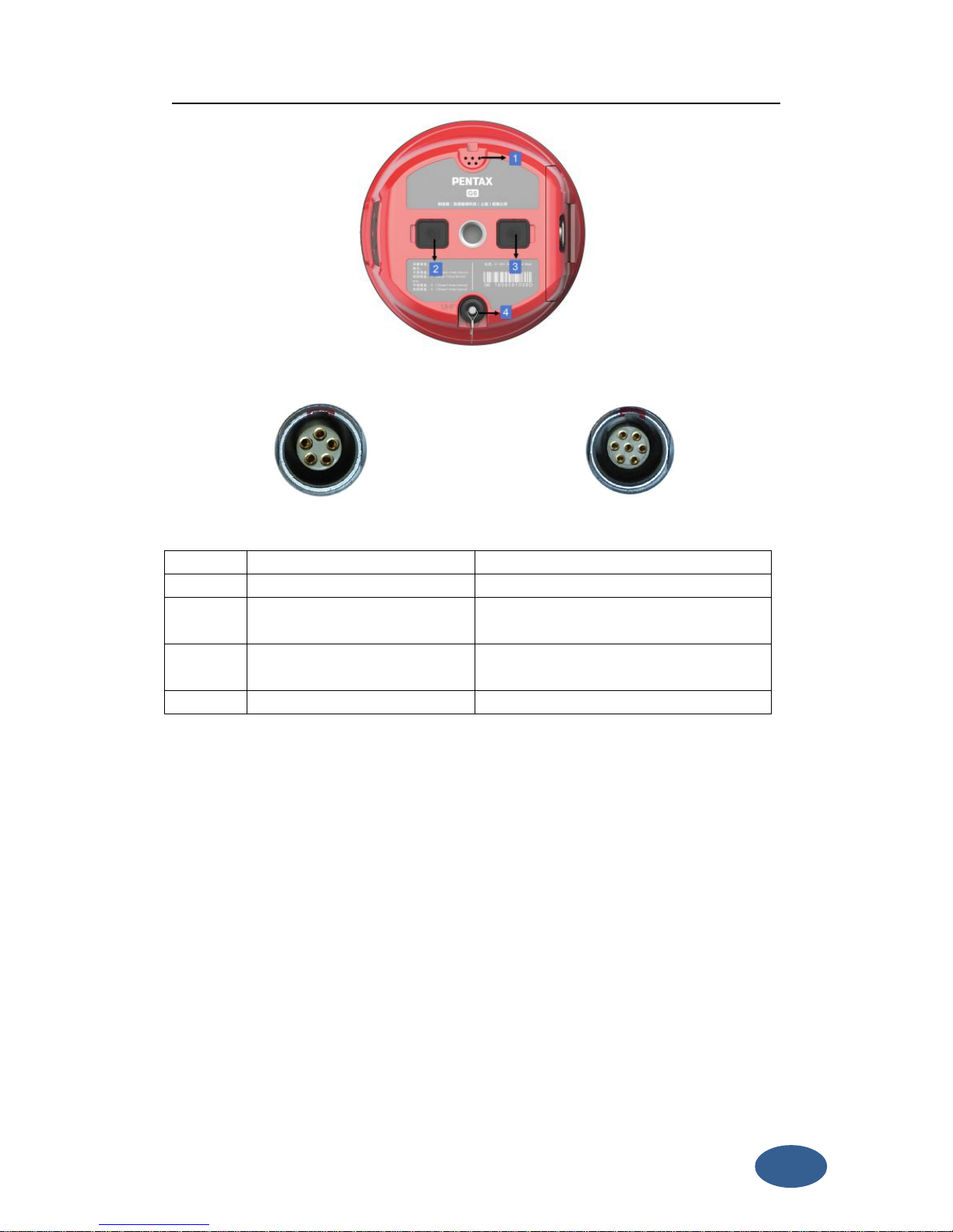
1.2.3. The bottom of Receiver
Page 9
9
Figure 1-6 G6 bottom
Figure 1- 11 5-PIN interface Figure 1- 12 7-PIN interface
Number
Name
Function
1
Beeper
Broadcast voice message
2
5 pin interface
Connect to external radio and external
battery
3
7 pin interface
USB port, also can connect to the
controller via the multi-function cable
4
Radio antenna interface
Connect to radio antenna
Page 10

10
Chapter2 Basic operations of G6
In this section, we highlight the basic operations of G6. It includes the installation of
bas and rover, the operation of keys, switching working mode and datalink, self-test.
All of these basic operations are simple and easy. But they are very important.
2.1 The installation of base and rover
The installation of base
1. Install the tripod on the chosen position, level it and attach the receiver into
tribrach.
2. Attach the transmitting radio antenna into the port “UHF” if the data link is radio.
3. Switch on the receiver and select the base working mode. If it is not correct,
please see next paragraph 2.3 for understanding how to select the correct
working mode or you can change it later using the handheld software.
4. Switch on the handheld and start the software for the radio channel
configuration and inserting the base coordinates, otherwise it is possible to make
the settings by Web UI function.
The installation of rover
1. Fix the bracket on the pole, fix the handheld to the bracket, put the rover on the
pole and attach receiving antenna into the port “UHF”, depending on the
connection used.
2. Power on the receiver and select the rover working mode. If it is not correct,
please see next paragraph 2.3 for understanding how to select the correct working
mode or you can change it later using the handheld software.
3. Switch on the handheld and start the software, then you can do the advanced
setting of the instrument and finally start the survey.
Note: If you want to take very accurate measures (around or below cm accuracy), we
recommend you to use another tripod also for the rover.
Page 11

11
2.2 The operation of keys
There is a power key in the receiver, the operations are as follows.
Power key
The main function of power key is power on/off and confirm button.
Power on: when the Receiver is in the OFF status (no light), press the power key
for 2 seconds and release it, and then the receiver will enter the initialization
status. Then you will listen beep for three times and the voice broadcast the
current receiver status, it means the receiver powered on successful.
Power off: when the G6 receiver is in the ON status (power supply light ON),
press and hold power key for 3 seconds until all lights blink, then release the
power key and there will be a voice broadcast “power off”. Press the power key
to confirm, then G6 will be turned off.
2.3 Self-checking
If the indicators are abnormal or the receiver can’t work normally, for example the
Bluetooth can’t be connected, the radio mode can’t work, it can’t connect to the
CORS. Then you can use the automatic detection function, which is Receiver
self-checking. Self-checking will check GPS, radio, GSM, Bluetooth, WIFI and sensor.
During this procession, it has voice guide tell you whether it’s normal or not.
1.
When the receiver is in powered on status, keep press the power key for 3
seconds until a voice broadcast “if you want to turn off the device”, then release
the power key. Keep press the power key again for 3 seconds until you hear a
beep, then there will be voice broadcast “self-check” and you could release the
power key (The new device should be self-checked once).
2. In the process of device self-checking, there will be voice broadcast the test
results. For example, if the wifi self-check is successful, voice broadcast “WIFI
self- check OK” and the led always on until the self-checking is completed. For
example, if the WIFI self-check fails, voice broadcast “wifi self-check error”, the
led will continue blink and the buzzer beeps until you restart G6. Self-checking
Page 12

12
procedure lasts about 1 minute.
3. If each module led are ON (not blinking) and voice broadcast the self-checking
success (for example “self-check GPS OK” it means the modules could work
normally.
Note: After self-checking, built-in radio frequency will return to factory settings. If
necessary, please contact your local dealer to change the frequency to match your
usage.
2.4 Measure the antenna height
When we use G6 collect static data or set G6 on a known point as a base station,
the antenna height should be measured. Antenna height is actually the vertical
height of the phase center to ground measurement point. But there are differences
between different measure methods.
Base and Static mode antenna height measurement: You can measure from the
ground to the altimetry piece of the receiver, you can measure from the ground
(known point) to altimetry piece. In this situation you should select “Height to
altimetry piece”.
Rover mode antenna height measurement: Measure methods of rover mode
includes pole height, straight height and slant height.
(1) Pole height, the height of the carbon pole, we can read it from the pole, then
input to the software.
(2) Straight height, straight height it’s the antenna phase center height. Straight
height = the height from ground to bottom of Receiver + antenna phase
center to the bottom of receiver.
(3) Slant height, measure from ground to the altimetry piece of the receiver.
Select slant height in the software, then input the height you measured.
2.5 Sensor Calibrate
Activate tilt survey function is the first step, then it’s “Sensor Calibrate”. Some times
when you check “Sensor Calibrate”, it can’t be used. You should check
Configure—System Setting, make sure tilt survey function is opened.“Sensor
Calibrate” contains “Horizontal, Azimuth and Declination”, now describe them.
Page 13

13
Tips: 1. In order to make sure the accuracy, don’t replace battery during
calibration
2. The pole should be set on the same point during all of the steps.
(1) Horizontal Calibration
Horizontal calibration is actually calibrating the E-bubble. Click “Adjust—Sensor
Calibrate—Horizontal”.
Figure 2-1
Enter horizontal calibration interface, you will see an electrical bubble in the
screen. Center the carbon pole, make sure the physical bubble of the pole is in center
place, then click “Adjust” in the screen. It has a prompt tone which means the
horizontal calibrate is finished.
Tip: Before calibrate, when physical bubble is in center, the E-bubble may be not,
it’s normal. Because the sensor has deviation before calibrate. But after calibration,
the physical bubble and E-bubble will be in center together.
Page 14

14
Figure 2-2 Before celebration (left) after celebration (right)
(2) Azimuth Calibration
Click “Adjust—Sensor Calibrate—Azimuth”, then it will show the “Azimuth
calibration” interface.
Figure 2-3
As it shows in the interface, there are three steps to do, “Record Vertical, Record
Horizontal, Calibrate”. Record vertical and horizontal data is order to get enough
data to do the Azimuth Calibrate.
First step is “Record Vertical”, install the receiver to mini rotary table, as picture
shows. Then click “Record Vertical”, at the same time set the carbon pole on a point,
rotate the pole in a circle, the carbon pole is the center of rotation. The speed can’t
exceed 25°/s. Software will show a circle when you rotate the pole. Usually, when
Page 15

15
you finish a circle, the software will show the picture and have a beep sound.
But sometimes, you had finished the circle and the software show the circle,
software doesn’t transmit a beep sound and it doesn’t show “Record Horizontal” is
successful. It means some place of the circle doesn’t have enough data (You can
check it from the software), you should rotate it again in the place without enough
data.
Figure 2-4
Second step is “Record Horizontal”. It’s almost same as step 1. The only difference
is this time the receiver is installed to the pole directly, just as the figure shows.
Others are same.
Page 16

16
Figure 2-5
The last step is “Calibrate”. After step one and two, it will show 2 circles on the
screen. Then click “Calibrate”, it will calculate the parameter and ask you “Make sure
using the parameter?” Click “Yes”, the parameter will be applied.
Figure 2-6
(3) Declination Calibration
After “Horizontal Calibration” and “Azimuth Calibration”, now it’s the last
step—“Declination Calibration”. Click “Adjust—Sensor Calibrate—Declination” to
enter the interface. Declination Calibration also contains three steps, “Records Center,
Records Tilt and Calibrate”
Figure 2-7
(a) The first step is “Records center”. Keep the pole on the same point, make sure
the bubble is in center, click “Record center”, it will collect 10 center points.
Page 17

17
Figure 2-8
(b) The second step is “Records Tilt”. In this step, you should collect tilt points in
4 direction, and in every direction you should collect 10 tilt points. There are some
conditions to do this step.
① The pole should set on the same points during all of the steps when you are
collecting tilt points.
② The tilt angle should be between 25° to 35°. This angle will show in the
controller screen, so you can check it directly.
③ When you do this step, the controller should be fixed solution.
④ Collect tilt points in 4 directions, East, South, West and North. It also has a
angle to show the direction. 90° is for East, 180° is for South, 270° is for West, 0° is
for North. When you do this step, the angle should be closed to those angles. In each
direction, the receiver should be stable station.
Page 18

18
Figure 2-9
Follow these four principles, then you can collect tilt points in four different
directions. Each direction should has 10 points. As the picture shows, set the pole on
one point, when you do this step. The tilt angle is 25°~30°, and make sure the
receiver is stable to collect points.
Collect tilt points in four different directions:
Figure 2-10 East Figure 2-11 South
Page 19

19
Figure 2-12 West Figure 2-13 North
After success record centers and tilts, then we should apply this parameter to
project. Click “Correction” to calculate the parameters, if it exceed the limit, we
should do the Sensor Calibrate again. If it doesn’t we can apply it. The software will
give message on the screen.
Click “Correction” to apply. Input the Antenna height, if you use the quick release
adapter, the height should be pole height + 0.04m. For example, the pole height is
1.8m, if you use quick release adapter, the height will be 1.84m. Then click “OK” to
use.
Page 20

20
Figure 2-14
Then all steps of Sensor Calibrate are finished. You can collect points with this
function. It will make field work more convenient and reliable.
Page 21

21
Chapter3 Web UI function
G6 has WIFI function, it could work as a hotspot, then Phone, controller, PC and
other devices can connect its WIFI. The default WIFI name is device number, there is
no password for this WIFI.
After you power on the G6 receiver, you could search the hotspot via
phone/PC/controller. The hotspot name is the G6 serial number, and there is no
password (This WIFI don’t have the internet access, you could just login the web
page to view the receiver status and set modes).
Figure 3-1
After connecting the WIFI, input IP “192.168.10.1” into your web browser to open.
Then it will pop up a window. It ask for log account and password, default is:
Account: admin Password: password
Page 22

22
The Web UI contains Status, Information, Download, Management, and Settings. It
also can show the device number in the web.
3.1 Status
In Status, you can see the current work status of the receiver, some basic information.
Such as system mode, current datalink, coordinate, satellites, solution and so on. The
detailed information you can see from the picture.
Figure 3- 2 Status
3.2 Information
Then it’s the “Information”, this menu shows the information inside the receiver,
such as firmware version of the receiver, GNSS firmware version, GSM mode
information, sensor version, battery information and so on.
Page 23

23
Figure 3- 3 Information
3.3 Download
“Download” is for downloading static data, you can download the datas you want to
use, you also can package them together. The format of raw data is “.dat” version, if
you want to use “.Rine” version, you can select.
Figure 3- 4 Download
3.4 Management
“Management” includes many useful function. You can upgrade firmware, register
the receiver, make self-checking, change the log password and restart the receiver.
So “Management” will be used in many stations.
Page 24

24
Figure 3- 5 Management
3.4.1 Device register
The register code is a 32 digits and letters, you could register the device via WEB UI
function. The detailed steps as follow.
In management page, you could see “registration”. Input register code to “Authcode”
then click submit, the receiver will be registered.
Page 25

25
Figure 3- 6 Registration
You could also register device via controller. Connect G6 with the surpad software in
controller. Click “About”, you will see “Register instrument”, then click it. The last step
is inputting code, then finish registration.
3.5 Settings
“Settings” includes “Working Mode”, “Device Configuration” and “NMEA Message”.
All of these functions are very useful. Here will introduce every selection.
3.5.1. Working mode
You can select different work mode to configure, static, rover and base. In different
mode, there are different configuration you can make.
1 Static mode
As the pictures show, you can set cutoff angle, select satellites system, input the
point name, antenna height, PDOP threshold. And the antenna measurement and
collect interval. These are all the parameters can be used in static collection.
At last, there are two record options. If you activate auto record, it will collect data
automatic when you power on the receiver.
Page 26

26
Figure 3- 7 Static mode
2 Rover Mode
In rover mode, you can select different datalink. Different datalink also has different
options can be edited. The datalink includes UHF, Network, External and Bluetooth.
If you select UHF mode, then you can select radio channel and radio protocol as you
want. You also can select whether store the raw data. The interface is as follow:
Page 27

27
Figure 3- 8 Rover mode (UHF datalink)
If you select Network, then besides select satellites system and record raw data, the
most important is that you can input CORS information, such as IP, account. Then get
the mount point.
Page 28

28
Figure 3- 9 Rover mode (Network datalink)
If you select External, then it can connect to external radio. There is a very important
thing, the external serial port band rate, this should be same with external radio.
Page 29

29
Figure 3-10 Rover mode (External datalink)
Then the last it’s Bluetooth, after selecting the datalink as Bluetooth, there are little
option that you can configure, for example the cutoff angle, satellites system and
record raw data.
Figure 3- 11 Rover mode (Bluetooth datalink)
Page 30

30
3 Base Mode
Base mode also contains different datalink, most of the parameters are same. The
only difference is the base mode has some more options can be edited, shows as
follow. Others are same as rover.
Figure 3- 12 Base mode
3.5.2. Device configuration
Device configuration can finish many basic configurations via WEB UI function, such
as changing language, select time zone first storage and others.
Figure 3- 13 Device configuration
Page 31

31
3.5.3. NMEA Message
Here you can configure the NMEA message, turn on/ off them. If you need them out
put, you also could select the update frequency. The NMEA contains GGA, GSA, GST,
RMC, ZDA, GSV, VTG, GLL, GEDOP, GEREF, GESNR and GEVCV.
Figure 3- 14 NMEA message
Page 32

32
Chapter4 G6 standard accessories
On the basis of the configuration chosen (base or rover), some of these accessories
are included in the receiver bundle.
4.1 The case of G6
There are two kinds of G6 cases: Rover case and Base case. The inner layout of the
base case and rover case is different.
Base case has the room for external radio and rover case has the room for the
controller. You can distinguish them from nameplate.
4.2 Power supply
Batteries
Every receiver could be inserted two batteries. The battery is “lithium-ion” battery
(7.4 V - 3350 mAh): a technology which has a higher energy-to-weight ratio with
respect to NiCd or NiMh batteries, no memory effect, and slow self-discharge when
not in use.
Figure 4- 1 Lithium-ion battery
Charger
The charger can charge two batteries simultaneously. The lights of the charger show
if the battery is being charged (red light CHARGE) or if it’s already charged (green
light FULL).
4.3 The antennas
G6 adopts a UHF all-direction transmitting and receiving antenna. Since there are
three different internal radio settings with different frequency range, the
Page 33

33
corresponding antennas have different length. The available range are: 410-430 MHz,
430-450 MHz and 450-470 MHz. They are suitable for field surveying, light and
durable. The gain is 4 dBi.
410-430MHz
430-450MHz
450-470MHz
Figure 4- 2 built-in radio antenna (not in scale)
4.4 Other accessories
The other accessories are: 25cm supporting pole, bracket, connector between
receiver and tribrach, and quick connector.
Table 4-1 Other accessories
No
Name
Figure(not in scale
)
1
25cm support pole
2
Bracket
3
Connector between
tribrach and receiver
4
Quick connector
Page 34

34
Appendix 1 Default radio configuration
The frequency and protocol of the 8 channels could be modified via Web UI or
controller. So you could change it easily. And the Frequency range is from 410MHz to
470MHz, so you can elect as you want.
Channel
Frequency
Protocol
1
441.00MHz
Trimtalk 450S
2
442.00MHz
Trimtalk 450S
3
443.00MHz
Trimtalk 450S
4
444.00MHz
Trimtalk 450S
5
445.00MHz
Trimtalk 450S
6
446.00MHz
Trimtalk 450S
7
447.00MHz
Trimtalk 450S
8
448.00MHz
Trimtalk 450S
Appendix 2 Voice messages
No.
Voice messages
Description
1
Rover
It will broadcast “rover” if the current Working mode is rover.
2
Base
It will broadcast “base” if the current Working mode is base.
3
Static
It will broadcast “static” if the current Working mode is static.
4
Single
It will broadcast when the Solution change to single.
5
RTD
It will broadcast when the Solution change to RTD.
6
Float
It will broadcast when the Solution change to Float.
7
Fixed
It will broadcast when the Solution change to fixed.
8OKIt will broadcast when the self-check successful.
9
Power off
It will broadcast when power off the receiver.
10
Start record
It will broadcast when receiver start record data in static.
Page 35

35
11
Error
It will broadcast when the self-check failed.
12
Self check
It will broadcast when start self- check.
13
GPS self check
It will broadcast when self-check the GPS module.
14
Radio self check
It will broadcast when self-check the radio module.
15
3G self check
It will broadcast when self-check the 3G module.
16
WIFI self check
It will broadcast when self-check the WIFI module.
17
Bluetooth self check
It will broadcast when self-check the Bluetooth module.
18
Sensor self check
It will broadcast when self-check the sensor module.
Appendix 3 Specification
Mod e l
G6Tc
G6N c
We i ght (w i th bat t e ry )
Abo u t 1k g
Size ( mm )
Ф13 1 × H 102
Ф13 1 × H 102
Ope r a ti n g ti m e
> 10 ho u rs
> 1 0 ho u rs
ROM
4G
4G
Cha n ne l s
220
120
Upd a te rat e
1Hz ~ 20Hz
1Hz ~ 5 0H z
Col d sta rt t i me
45s
Hot star t ti m e
30s
Page 36

36
Ope r a ti n g te m p.
- 3 0 ℃ ~ + 65 ℃
Sto r a ge tem p .
- 4 0 ℃ ~ + 75 ℃
Protection class
IP6 7
Radio Modem
Bui l t- i n
Rad i o po w er
1W
Data format
RTCM 、 NM E A
RTK Initiation Reliability
99. 9 9%
Han d he l d
Operating system
Win d ows mo b il e 6. 5
Ope r a ti n g so ftw a re
Sur p ad 3.0
Acc u rac y
Dyn a mi c
Hori zon t a l
±(8 +1×10
-
6
)mm
Ver ti c al
±( 15 +1×10
-
6
) mm
Stat i c
Hori zon t a l
±(2.5+1×10
-
6
)mm
Ver ti c al
±(5+1×10
-
6
)mm
 Loading...