

Page 1
Section 11—Focal-Plane Shutters
ou've seen that the blade-type shutter sits behind the
lens or between lens elements. By contrast, the focal-
Y
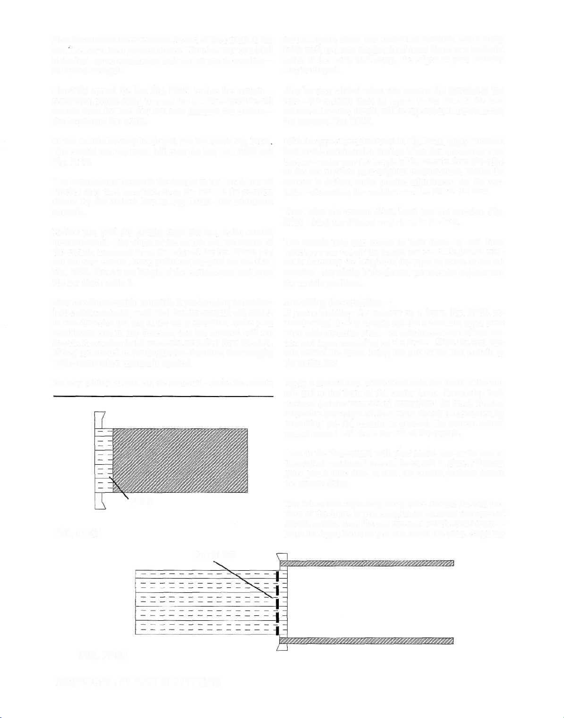
plane shutter sits just in front of the camera's film aperture.
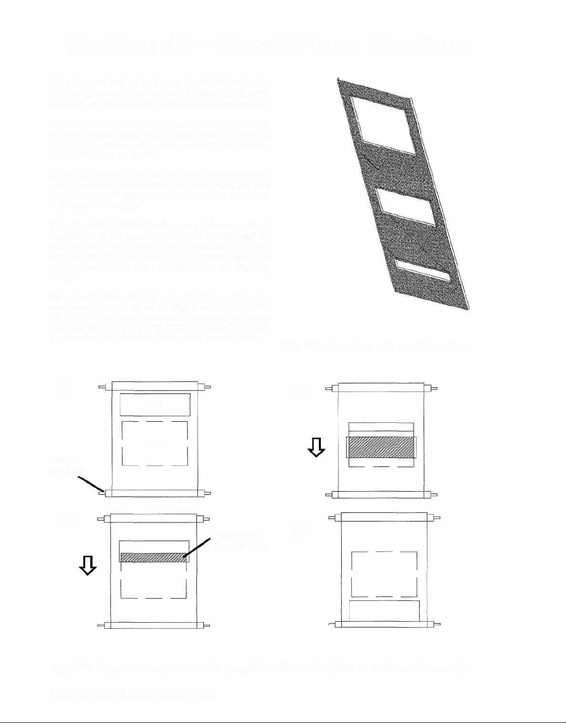
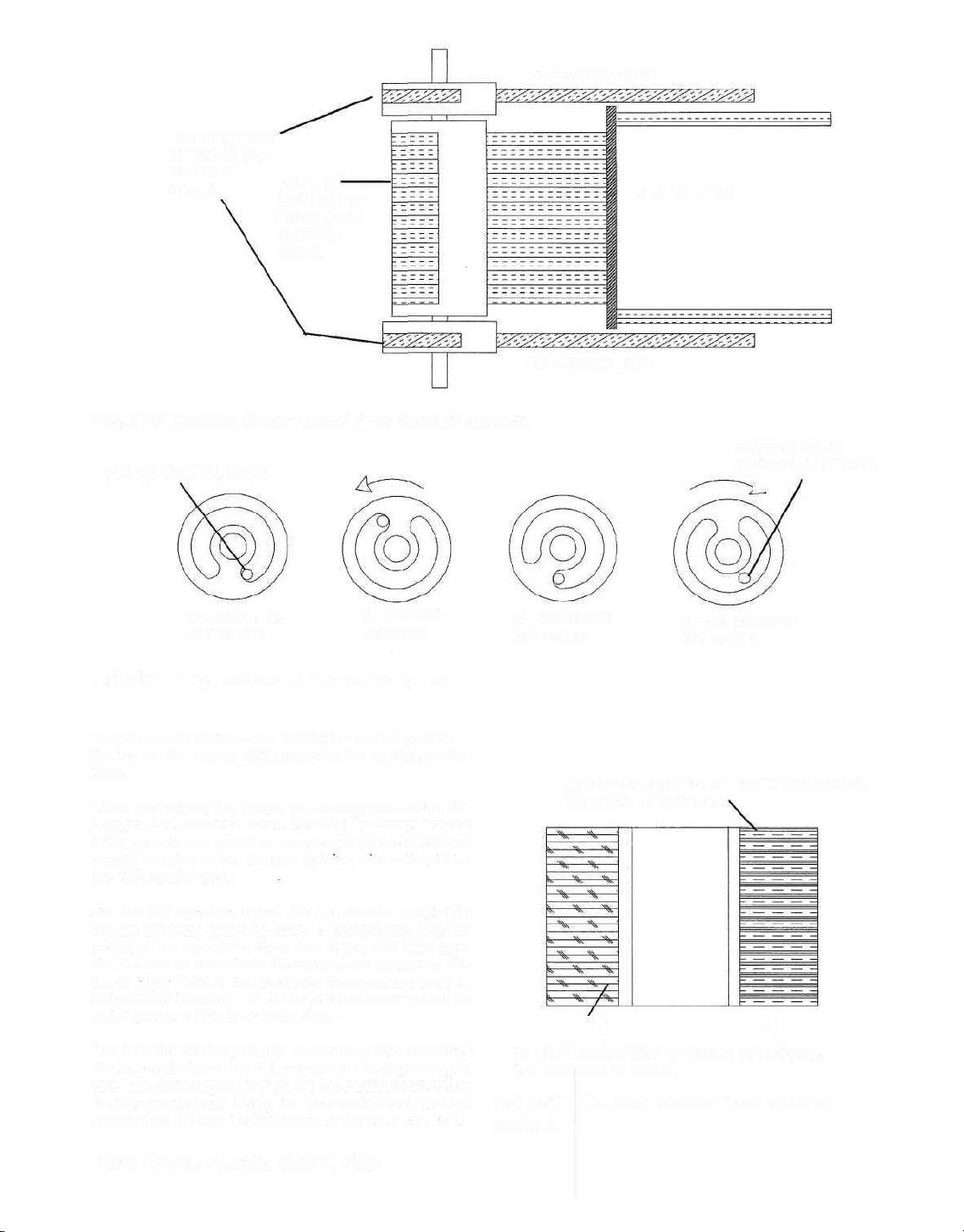
Some early focal-plane designs, such as the Speed Graph-
ics, use a single curtain with multiple openings ("slits" ),
Fig. FP1. Selecting a shutter speed determines which opening is used to expose the film.
Moving the curtain in the cocking direction also tensions a
spring—a spring located within the lower roller, Fig. FP2
(A). The tensioned spring is now ready to draw the curtain
in the release direction.
When you release the shutter, the spring pulls the curtain in
the direction of the arrow, Fig. FP2 (B). The film gets exposed as the curtain opening moves across the film opening, Fig. FP2 (C). At the end of the exposure cycle, the
curtain opening rests below the focal-plane aperture, Fig.
FP2 (D).
But notice that the entire frame doesn't get exposed at the
same time. First the top of the film is exposed, Fig. FP2
(D). Then, as the curtain continues moving in the release
direction, the rest of the film frame is exposed, Fig. FP2
(C). In effect, the slit wipes the exposure onto the film.
Fig. FP1 A curtain with multiple slits.
A
SLIT
FILM
LOWER
ROLLER
c
B
EXPOSED
AREA OF FILM
Fig. FP2 Exposure sequence with a multiple-slit curtain (view from front of camera).
D
108/FOCAL-PLANE SHUTTERS
Page 2
Two factors determine the actual exposure time (shutter
speed):
TAPE
1. the width of the opening used to expose the film
2. the speed at which the curtain travels.
For the slowest shutter speed, the curtain opening is as large
as the focal-plane aperture—the top slit in Fig. FPL As the
curtain moves in the release direction, the film is completely
uncovered—now the entire film frame sees the maximum
amount of light. But the curtain continues moving in the
release direction until it completely recovers the film.
As the curtain recovers the film, the top of the film frame
gets cut off first. The bottom of the film frame continues to
see light until the curtain opening moves below the aperture.
The fastest shutter-speed setting uses the smallest open-
ing—the bottom slit in Fig. FP1. Here, only a small section
of film sees light at a given moment.
Selecting a smaller slit decreases the amount of time that
any given film section receives light. Similarly, moving the
curtain at a faster speed decreases the length of time that
the film sees light. Either or both techniques may then be
used to provide different shutter speeds—providing differ-
ent curtain openings or changing the speed at which the
curtain travels.
The way most focal-plane shutters vary the exposure is by
changing the size of the curtain opening. Very few cameras
change the exposure time by speeding up or slowing down
the curtain. Varying the curtain-travel time (curtain speed)
requires changing the tension on the spring—the spring that
draws the curtain in the release direction.
1st CURTAIN
BAR
2nd CURTAIN
TENSION ROLLER
FIG. FP3 Curtains in a two-curtain focalplane shutter.
1st CURTAIN
A—CURTAINS IN RELEASED POSITION (BACK)
COCKING DIRECTION
1st CURTAIN
COVERS FILM
2nd CURTAIN COVERING FILM
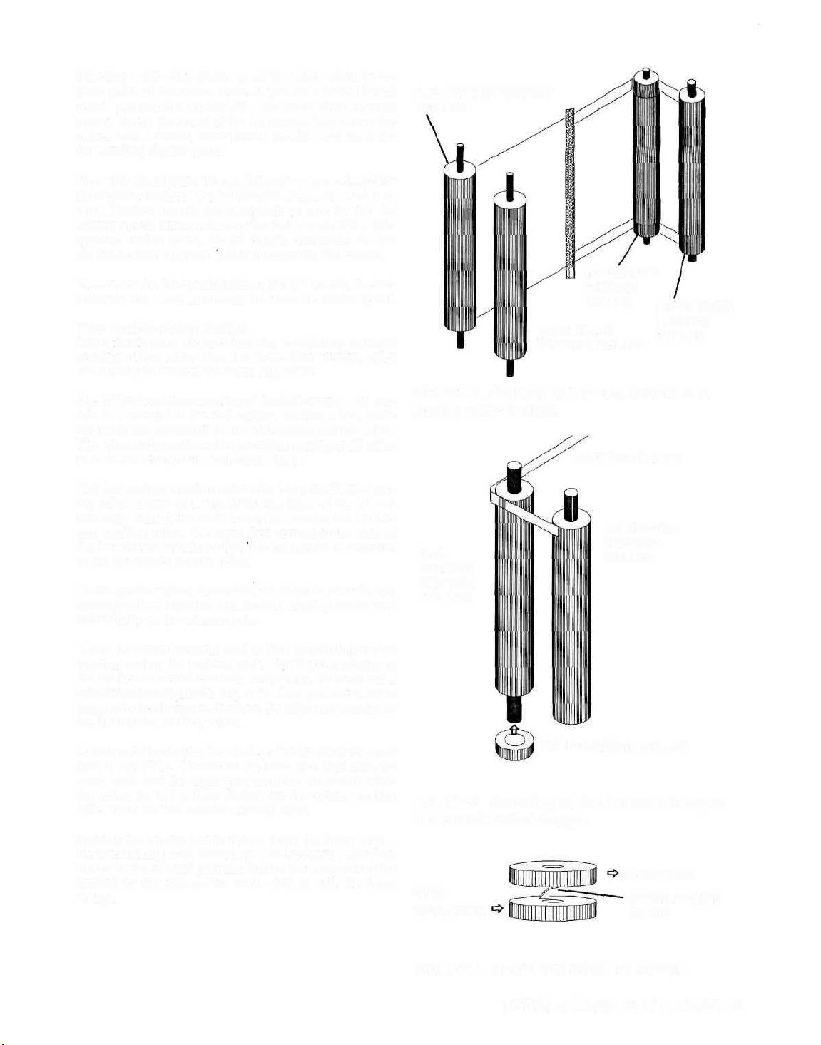
A single-curtain design has a limited range of shutter
speeds—the number of shutter speeds equals the number
of openings in the curtain. To achieve a full range of shutter
speeds, most focal-plane shutters use two curtains—the 1st
curtain and the 2nd curtain.
Each curtain connects to a spring-loaded roller—the ten-
sion (or take-up) roller, Fig. FP3. Each curtain has a pair
of thin cloth tapes—the tapes of the 2nd curtain are ce-
mented to the 2nd-curtain tension roller. The 1st curtain,
however, is cemented directly to its tension roller.
The other end of the 2nd-curtain is cemented to the 2nd-
curtain winding roller (not shown). Similarly, the tapes of
the 1st curtain are cemented to the lst-curtain winding roller.
The curtains and tapes are also cemented to the thin, metal
curtain bars, Fig. FP3.
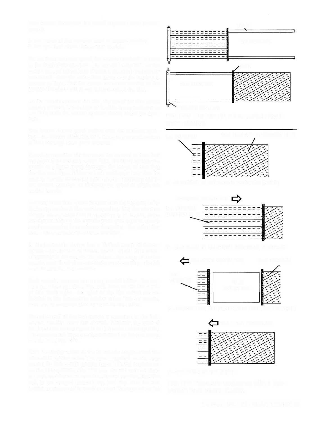
With the shutter released, the 1st curtain wraps around the
1st-curtain tension roller. The tapes of the 2nd curtain wrap
around the 2nd-curtain tension roller. The 2nd curtain covers the film aperture, Fig. FP4 (A). As you cock toe shutter, both curtains move from the released position, Fig. FP4
(A), to the charged position, Fig. FP4 (B). Now the 2nd
curtain wraps around its winding roller. The tapes of the 1st
B—CURTAINS IN CHARGED (COCKED) POSITION
| RELEASE DIRECTION
1st
CURTAIN
C—1st CURTAIN RELEASED, 2nd CURTAIN LATCHED
d—2nd CURTAIN RELEASED
FILM
APERTURE
RELEASE DIRECTION
2nd CURTAIN
FIG. FP4 Exposure sequence with a twocurtain focal-plane shutter.
FOCAL-PLANE SHUTTERS/109
Page 3
curtain wrap around the lst-curtain winding roller. Notice
that the curtains overlap one another during the cocking
movement. This curtain overlap prevents light from reach-
ing the film.
Now, with the shutter charged, the 1st curtain covers the
film aperture. The springs insided the tension rollers have
been tensioned—both springs want to pull their respective
curtains in the release direction. But each curtain is now
latched—the 1st-curtain latch holds the 1st curtain, and the
2nd-curtain latch holds the 2nd curtain. The latches prevent the springs from pulling the curtains in the release
direction.
RELEASE
DIRECTION
1st CURTAIN
FILM APERTURE
2nd CURTAIN
Releasing the shutter disengages the lst-curtain latch. Now
the 1st curtain moves across the aperture in the release direction, Fig. FP4 (C). Since the 2nd curtain remains latched
by the 2nd-curtain latch, the shutter opens—the film sees
light as the 1st curtain moves.
The right-hand edge of the film in Fig. FP4 (C) sees light
first, The film then gets progressively uncovered as the 1st
curtain moves. Finally, the 1st curtain reaches the other side
of the aperture, completely uncovering the film.
Next the speed-control mechanism of the camera disengages
the 2nd-curtain latch. Now the 2nd curtain moves across
the aperture. The 2nd curtain progressively covers the film,
ending the exposure to each part of the film in turn. Finally,
the 2nd curtain reaches the end of its travel at the other side
of the aperture, Fig. FP4 (D).
The sequence we've just described is called the full-aper-
ture shutter speed—the 2nd curtain is released when the 1st
curtain reaches the closing side of the aperture. For a moinenl, the entire film frame receives light. The full-aperture
shutter speed depends on how fast the curtains travel and
the exact moment that the 2nd curtain is released. In the
classics and antiques, the full-aperture shutter speed is typically around 1/30 to 1/60 second.
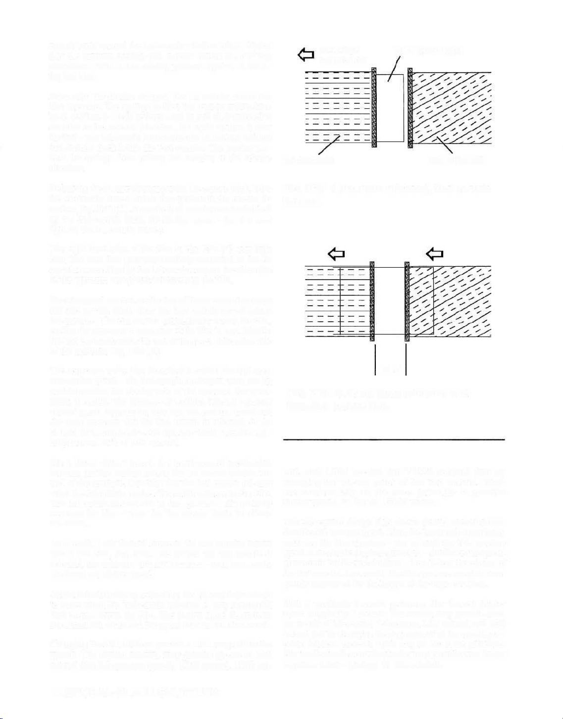
For a faster shutter speed, the speed-control mechanism
releases the 2nd curtain before the 1st curtain reaches the
end of the aperture. Consider that the 2nd curtain releases
when the 1st curtain reaches the position shown in Fig. FP5.
The 1st curtain is then still in the aperture—still partially
covering the film—when the 2nd curtain starts its release
movement.
As a result, a slit formed between the two curtains moves
across the film, Fig. FP6. The sooner the 2nd curtain is
released, the narrower this slit becomes—and, as a result,
the faster the shutter speed.
At the fastest shutter-speed setting, the 1st curtain just starts
to move when the 2nd curtain releases. A very narrow slit
then moves across the film. The shutter speed depends on
the actual slit width and the speed that the curtains travel.
Changing the slit width can provide a wide range of shutter
speeds. The classic cameras may provide speeds of 1/60
second (the full-aperture speed), 1/125 second, 1/250 sec-
FIG. FP5 1st curtain released, 2nd curtain
latched.
SLIT
FIG. FP6 Both curtains released and
traveling across film.
ond, and 1/500 second (or 1/1000 second) just by
changing the release point of the 2nd curtain. Modern cameras rely on the same principle to provide
shutter speeds as fast as 1/8000 second.
The two-curtain design also allows shutter speeds slower
than the full-aperture speed. Here, the 1st curtain completely
uncovers the film aperture—just as with the full-aperture
speed. A mechanical speeds governor—similar to the speeds
governor in blade-type shutters—then delays the release of
the 2nd curtain. As a result, the film aperture remains completely uncovered for the length of the exposure time.
With a mechanical speeds governor, the slowest shutter
speed is typically 1 second. The camera may provide shutter speeds of 1/2 second, 1/4 second, 1/15 second, and 1/30
second just by changing the engagement of the speeds governor. Modern cameras again rely on the same principle.
But the electronic controls of today may provide even longer
exposure times—perhaps 30 full seconds.
110/FOCAL-PLANE SHUTTERS
Page 4
THE CURTAIN ROLLERS
ach curtain has its own spring-loaded tension roller—
when the curtain is released, its tension roller pulls it to
E
the released position. Each curtain also has its own winding roller to draw the curtain to the cocked position.
The drum design
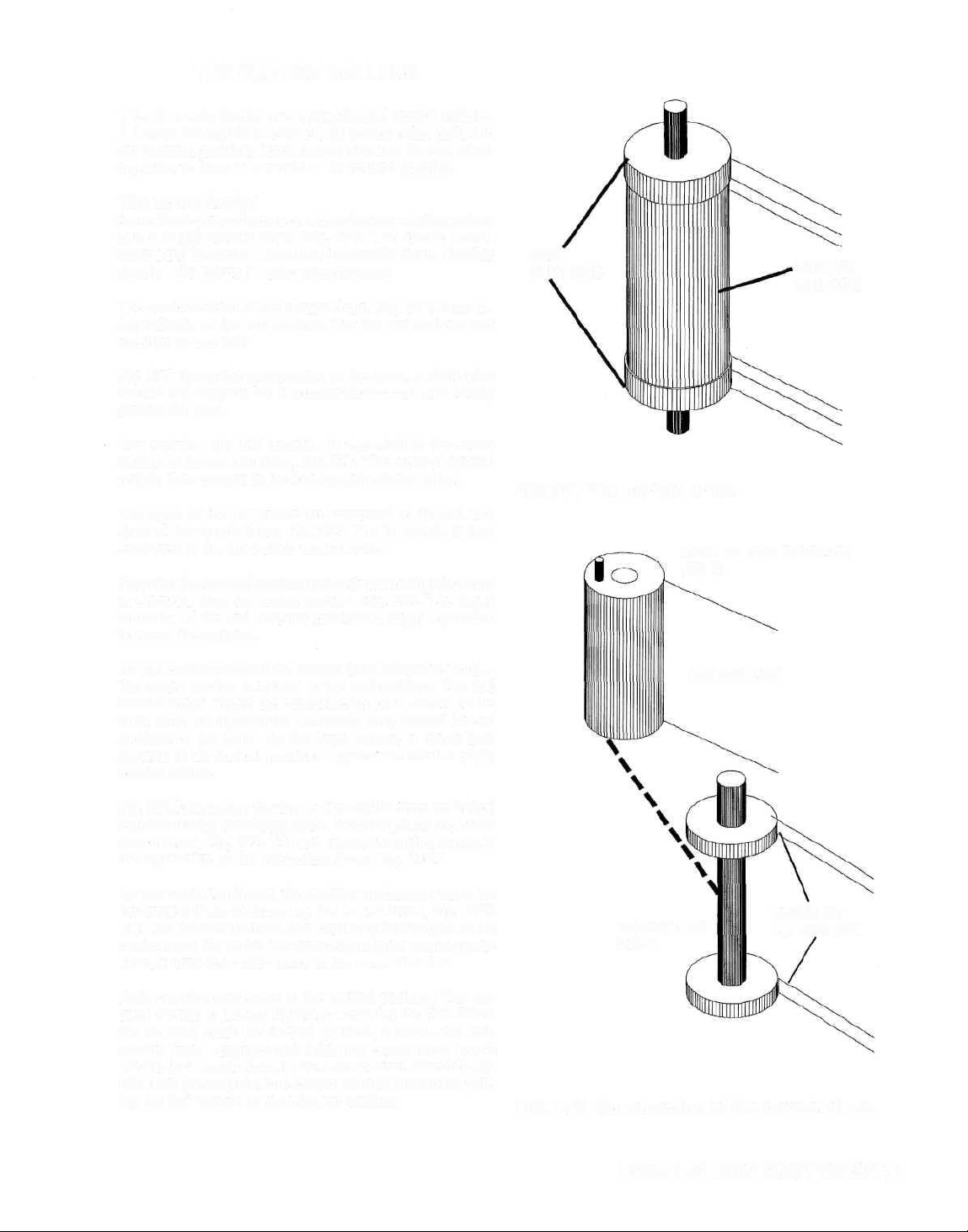
Some focal-plane shutters combine the two winding rollers
into a single curtain drum, Fig. FP7. The classic screwmount and M-series Leicas use the curtain drum. Another
classic—the Nikon F—also uses the drum.
The center section of the curtain drum, Fig. FP7, turns independently of the end sections. But the end sections turn
together as one unit.
Fig. FF8 shows the construction of the drum. A shaft joins
the two end sections. But the center section can rotate freely
around the shaft.
One curtain—the 2nd curtain—is cemented to the center
section of the curtain drum, Fig. FP9. The tapes of the 2nd
curtain then cement to the 2nd-curtain tension roller.
The tapes of the 1st curtain are cemented to the end sec-
tions of the curtain drum, Fig. FP9. The 1st curtain is then
cemented to the lst-curtain tension roller.
Note that the two end sections of the drum are slightly larger
in diameter than the center section, Fig, FP9. The larger
diameter of the end sections provides a slight separation
between the curtains.
END
SECTIONS
FIG. FP7The curtain drum.
CENTER (2nd-CURTAIN)
DRUM
CENTER
SECTION
As you cock the shutter, the curtain drum rotates as a unit—
the center section is locked to the end sections. The 2nd
curtain wraps around the center section of the drum. At the
same lime, the tapes of the 1 st curtain wrap around the end
sections of the drum. As the drum rotates, it draws both
curtains to the cocked position—against the tension of the
tension rollers.
Fig. FP10 shows how the two sections of the drum are locked
together during the charge cycle. Note the pin on top of the
center drum, Fig. FP8. The pin passes through a cutout in
the top section of the lst-curtain drum, Fig. FP10.
As you cock the shutter, the cocking mechanism turns the
lst-curtain drum as shown by the curved arrow, Fig. FP10
(B). The lst-curtain drum then comes against the pin on the
center drum. So, as the lst-curtain drum turns counterclock-
wise, it turns the center drum in the same direction.
Both curtains now move to the cocked position. The cur-
tains overlap to prevent light from reaching the film. When
the curtains reach the cocked position, a latch—the 2nd-
curtain latch—engages and holds the center drum (you'll
see the 2nd-curtain latch in the next section). The 2nd-cur-
tain latch prevents the 2nd-curtain tension roller from pull-
ing the 2nd curtain to the released position.
2nd CURTAIN
1st-CURTAIN
DRUM
TAPES OF
1st CURTAIN
FIG. FP8 Construction of the curtain drum.
FOCAL-PLANE SHUTTERS/111
Page 5
END SECTIONS
OF DRUM (1stCURTAIN
DRUM)
CENTER
SECTION OF
DRUM (2ndCURTAIN
DRUM)
FIG. FP9 Curtain drum viewed from front of camera.
PIN ON CENTER DRUM
1st-CURTAIN TAPE
2nd CURTAIN
1st-CURTAIN TAPE
CENTER DRUM
REMAINS LATCHED
A
A—SHUTTER
RELEASED
B—DURING
CHARGE
FIG, FP10 Top section of 1st-curtain drum.
The lst-curtain drum is also held in the cocked position—
the lst-curtain drum is still engaged to the cocking mechanism.
When you release the shutter, the cocking mechanism disengages the lst-curtain drum. Now the 1st-curtain tension
roller pulls the 1st curtain to the released position. The 2nd
curtain remains in the charged position—it's still held by
the 2nd-curtain latch.
For the full-aperture speed, the 1st curtain completely
crosses the focal-plane aperture. A disengaging lever attached to the lst-curtain drum then strikes and disengages
the 2nd-curtain latch. Now the center drum can rotate. Notice in Fig. FP10 (D) that the center drum can turn freely in
a clockwise direction—its pin no longer comes against the
upper section of the lst-curtain drum.
But for a slit-width speed, the center drum releases before
the 1st curtain has completely crossed the focal-plane aperture. The disengaging lever on the lst-curtain drum strikes
(the 2nd-curtain latch during the lst-curtain travel. The 2nd
curtain then follows the 1st curtain as shown in Fig. FP11.
C—CURTAINS
CHARGED
(1) OUTER SECTION OF DRUM RELEASES,
1st CURTAIN TRAVELS
(2) CENTER SECTION OF DRUM RELEASES,
2nd CURTAIN TRAVELS
D—1st CURTAIN
RELEASED
FIG. FP11 Curtains viewed from front of
camera.
112/FOCAL-PLANE SHUTTERS
Page 6
Selecting a slit-width shutter speed then determines the release point of the center drum. If you set a faster shutter
speed, you select a smaller slit—the center drum releases
sooner during the travel of the 1st curtain. The sooner the
center drum releases, the narrower the slit—and the faster
the resulting shutter speed.
From this description, we can determine a general rule for
focal-plane shutters: The 1st curtain releases the 2nd curtain. Further, the slit width depends on how far the 1st
curtain travels before releasing the 2nd curtain. For a fullaperture shutter speed, the 1st curtain completely crosses
the focal-plane aperture; it then releases the 2nd curtain.
The sooner the 1st curtain releases the 2nd curtain, the narrower the slit—and, as a result, the faster the shutter speed.
The double-roller design
Other focal-plane shutters use two completely separate
winding rollers rather than the drum. One winding roller
sits directly in front of the other, Fig. FP12.
Fig. FP12 shows the mounting of the 2nd curtain—the curtain is cemented to the 2nd-curtain winding roller, while
the tapes are cemented to the 2nd-curtain tension roller.
The 1st-curtain tension roller has a free-turning small roller
at each end to route the 2nd-cutain tapes.
The 2nd-curtain winding roller also has a small free-turning roller at each end, Fig. FP13. The tapes of the 1st curtain wrap around the small rollers en route to the Ist-curtain winding roller. The tapes then cement to (the ends of
the lst-curtain winding roller. The 1st curtain is cemented
to the 1st-curtain tension roller.
To charge the shutter, the cocking mechanism turns the two
winding rollers together. But the two winding rollers turn
individually on the release cycle.
2nd-CURTAIN WINDING
ROLLER
1st-CURTAIN
TENSION
ROLLER 2nd-CURTAIN
1st-CURTAIN
WINDING ROLLER
TENSION
ROLLER
FIG. FP12 Position of the 2nd curtain in a
double-roller design.
1st-CURTAIN TAPE
1st-CURTAIN
2ndCURTAIN
WINDING
ROLLER
WINDING
ROLLER
There are several systems used to lock the winding rollers
together during the cocking cycle. You'll see examples in
the studies of actual cameras. Frequently, cameras use a
pair of interlocking studs, Fig. FP14. One gear in Fig. FP14
couples to the charge mechanism; the other gear couples to
the 1st-curtain winding roller.
As you cock the shutter, the wind mechanism turns the lower
gear in Fig. FP14. The stud on the lower gear then turns the
upper gear. And the upper gear turns the 1st-curtain wind-
ing roller. As in the drum design, the 1st-curtain winding
roller turns the 2nd-curtain winding roller.
Pushing the release button moves down the lower gear—
the interlocking studs disengage. The 1st curtain, now free,
moves to the released position. But the 2nd curtain remains
latched by the 2nd-curtain latch—just as with the drum
design.
FREE-TURNING ROLLER
FIG. FP13 Mounting of the 1st curtain tapes
in a double-roller design.
1st CURTAIN
WIND
MECHANISM
INTERLOCKING
STUDS
FIG. FP14 Gears that wind 1st curtain.
FOCAL-PLANE SHUTTERS/113
Page 7

SPEED CONTROL IN THE FOCAL-PLANE
SHUTTER
o control the release point of the 2nd curtain, we'll first
add the latching system—the mechanism that latches
T
the 2nd curtain in the charged position. In Fig. FP15, we've
added a latching cam to the top pivot of the 2nd-curtain
winding roller. Remember, the 2nd-curtain winding roller
winds on the 2nd curtain during the cocking cycle.
We now need a latch—the 2nd-curtain latch—to engage
the latching cam. Fig. FP16 shows the top view of the latching cam and the 2nd-curtain latch. In Fig. FP16 A, the curtains are in the released position. As you cock the shutter—
and the 2nd-curtain winding roller winds on the 2nd curtain—the latching cam rotates as shown in Fig. FP16B.
As the latching cam nears the charged position, it pushes
aside the 2nd-curtain latch, Fig. FP16B. The latching cam
travels slightly further to the position shown in Fig. FP16C—
the 2nd-curtain latch then drops into engagement with the
latching cam.
Now the 2nd-curtain tension roller tries to pull the 2ndcurtain winding roller in the release direction, Fig. FP16C.
But the 2nd-curtain latch holds the latching cam, preventing the 2nd-curtain winding roller from turning.
Releasing the shutter disengages the 1st curtain—the 2nd
curtain remains held by the 2nd-curtain latch, Fig. FP16C.
Remember that the release point of the 2nd curtain depends
on how far the 1st curtain has traveled. Consequently, the
part that releases the 2nd curtain typically moves with the
1st curtain. For the full-aperture speed, the 1 st curtain com-
pletely crosses the focal-plane aperture. The part rotating
with the lst-curtain winding roller then strikes the 2nd-cur-
tain latch.
LATCHING
CAM
2nd-CURTAlN
WINDING
ROLLER
2nd CURTAIN
FIG. FP15 Top of 2nd-curtain winding roller.
2nd-CURTAIN
LATCH
LATCHING
CAM
A—SHUTTER
RELEASED
Disengaging the 2nd-curtain latch frees the 2nd curtain. As
the 2nd curtain moves across the aperture, the latching cam
rotates as shown in Fig. FP16D.
For a faster shutter speed, the 1st curtain disengages the
2nd-curtain latch sooner—before the 1st curtain has completely crossed the focal-plane aperture. The sooner the 1st
curtain disengages the 2nd-curtain latch, the smaller the
slit width—and the faster the exposure time.
114/FOCAL-PLANE SHUTTERS
B—DURING COCKING
CYCLE
C—2nd CURTAIN
LATCHED
D—2nd CURTAIN
RELEASED
FIG. FP16 Latching sequence for 2ndcurtain winding roller.
Page 8
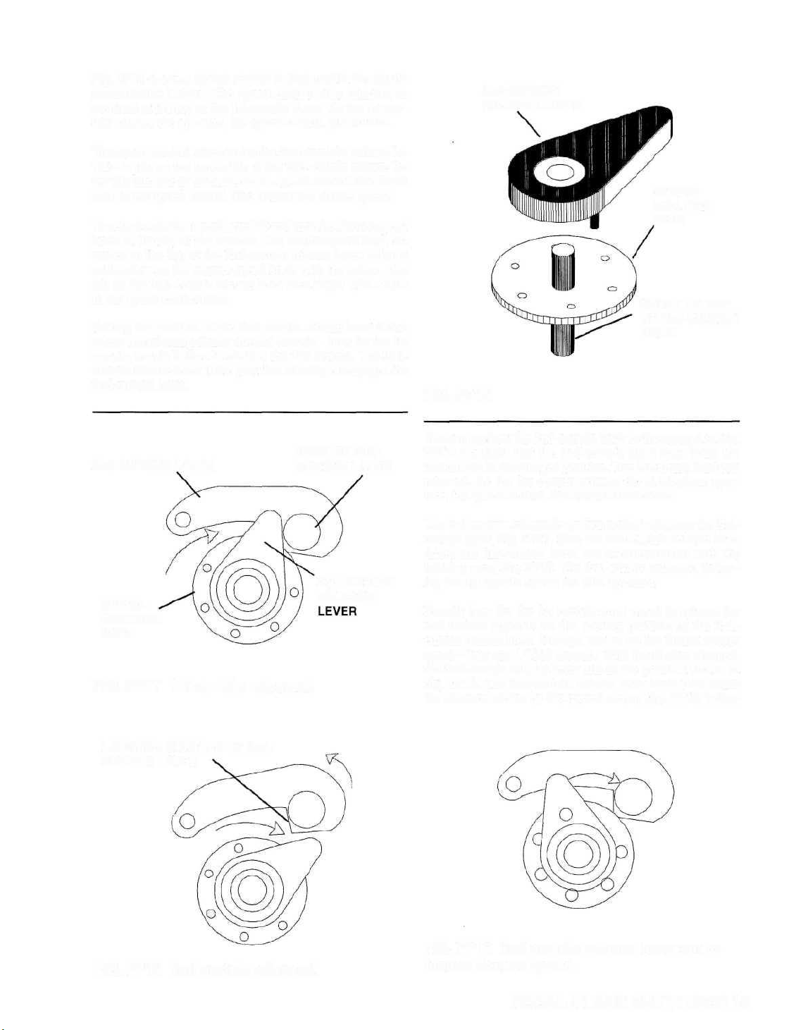
Fig. FP16 shows a system similar to that used in the classic
screw-mount Leicas. The speed-control disc attaches to
the shaft at the top of the lst-curtain drum. As the 1st curtain crosses the aperture, the speed-control disc rotates.
The speed-control disc carries the 2nd-curtain release lever—a pin on the underside of the 2nd-curtain release le-
ver fits into one of the holes in the speed-control disc. Each
hole in the speed-control disc relates to a shutter speed.
To select a shutter speed, you lift and turn the shutter-speed
knob at the top of the camera. The shutter-speed knob at-
taches to the top of the 2nd-curtain release lever. Align a
calibration on the shutter-speed knob with the index—the
pin on the 2nd-curtain release lever then aligns with a hole
in the speed-control disc.
Setting the position of the 2nd-curtain release lever deter-
mines the release point of the 2nd-curtain—how far the 1st
curtain travels before it releases the 2nd curtain. The 2ndcurtain release lever is the part that actually disengages the
2nd-curtain latch.
2nd-CURTAIN
RELEASE LEVER
SPEEDCONTROL
DISC
SHAFT ON TOP
OF 2nd-CURTAIN
DRUM
FIG. FP16
2nd-CURTAIN LATCH
SPEEDCONTROL
DISC
POST ON 2ndCURTAIN LATCH
FIG. FP17 1st curtain released.
LATCHING SURFACE OF 2ndCURTAIN LATCH
2nd-CURTAIN
RELEASE
You can see how the 2nd-curtain latch is disengaged in Fig.
FP17. Consider that the 2nd-curtain latch now holds the
2ndcurtain in the charged position. The 1st curtain has been
released. As the 1st curtain crosses the focal-plane aperture, the speed-control disc rotates clockwise.
The 2nd-curtain release lever then strikes a post on the 2ndcurtain latch, Fig. FP17. Now the 2nd-curtain release lever
drives the 2nd-curtain latch out of engagement with the
latching cam, Fig. FP18. The 2nd curtain releases, following the 1st curtain across the film aperture.
Exactly how far the 1st curtain must travel to release the
2nd curtain depends on the starling position of the 2ndcurtain release lever. Perhaps you've set the fastest shutter
speed—let's say 1/1000 second. With the shutter charged,
the 2nd-curtain release lever sits at the position shown in
Fig. FP19. The 2nd-curtain release lever must then rotate
the distance shown by the curved arrow, Fig. FP 19, before
FIG. FP18 2nd curtain released.
FIG. FP19 2nd-curtain release lever set to
fastest shutter speed.
FOCAL-PLANE SHUTTERS/115
Page 9

CHECKING AND ADJUSTING SHUTTER SPEEDS WITH A FOCAL-PLANE SHUTTER
camera-repair shop uses a specialized electronic tester
to check shutter speeds. If you're in the business of
A
restoring antiques and classics, you may want to invest in
such equipment. But if restoring antiques is a hobby, you
probably can't justify the expense.
As with blade-type shutters, however, the important thing
with antique focal-plane shutters may be proper operation—
not point-blank accuracy. You should be able to visually
detect a difference in the slow speeds. At the 1-second setting, the 2nd curtain should run smoothly through the slowspeed governor.
You can also visually check the fast speeds with a focalplane shutter. Open the camera back and remove the lens.
Now hold the lens opening to a light source. Watch through
the focal-plane aperture at the back of the camera as you
release the shutter.
As you change the shutter speeds in the slit-width range,
you should be able to detect a difference—the light flash
appears darker at each faster shutter-speed setting.
If you use a fluorescent lamp, you can even get a visual
indication as to the accuracy of the shutter. The pulses of
the fluorescent light capture the slit in different positions.
At 1/1000 second, you should see three slits, Fig FP23. At
1/500 second, you should see two slits.
FIG. FP23 Exposure with a fluorescent lamp at
1/1000 second.
Full aperture1/60 second
Another technique you can use is to watch the flash expo-
sure at the slit-width shutter speeds. With electronic flash,
you'll see only the portion of the aperture that's uncovered
when you fire the flash. Point the electronic-flash unit to-
ward a white wall. Set the camera to X sync, and watch the
wall through the back of the focal-plane aperture as you
release the shutter.
At the full-aperture shutter speed, you should see the full
focal-plane aperture, Fig. FP24. But at each faster shutter
speed, you should see only part of the aperture—a smaller
portion illuminated at each faster shutter speed. At 1/500
second and 1/1000 second, you may see no flash through
the aperture at all.
Checking and adjusting curtain tensions—
Focal-plane shutters have individual tension adjustments
for each curtain. The two curtains should be traveling at the
same speed.
If the 1st curtain is traveling faster than the 2nd curtain, the
slit gets wider as it crosses the aperture. The exposure on
the closing side of the aperture is then longer than the exposure at the opening side of the aperture. The effect of the
error is the most severe at the fastest shutter speed—the
shutter speed with the narrowest slit.
The problem may even worse if the 2nd curtain travels faster
than the 1st curtain. The slit then gets narrower as it crosses
1/125 second
1/250 second
FIG. FP24 Exposure with an electronic-flash
unit—curtain travel is from right to left.
FOCAL-PLANE SHUTTERS/117
Page 10
striking the post on the 2nd-curtain latch. The 1st curtain
barely enters the aperture before the 2nd curtain is released.
To set the next speed—1/500 second—lift and turn the
2nd-curtain release lever one position counterclockwise. The
pin on the 2nd-curtain release lever now fits in the 1/500second hole, Fig. FP21. Comparing Fig. FP20 with Fig.
FP21, you can see that the 2nd-curtain release lever must
now travel a greater distance clockwise before it strikes the
2nd-curtain latch. The 1st curtain travels that much further,
resulting in a larger slit.
For the full-aperture shutter speed, the 2nd-curtain release
lever sits in the 1/30-second hole, Fig. FP21. Now the 1st
curtain completely crosses the focal-plane aperture before
releasing the 2nd curtain.
SLOW SPEEDS WITH THE FOCAL-PLANE
SHUTTER
or the slow speeds—the speeds slower than the full-
aperture speed—the 2nd-curtain release lever sits at the
F
full-aperture position—the 1/30-sccond hole in Fig. FP21.
The 1st curtain then completely crosses the focal-plane aperture and releases the 2nd curtain.
So far, the operation is the same as it is at the full-aperture
speed. But setting a slow shutter speed also engages the
slow-speed governor. Once the 2nd curtain starts to move,
the slow-speed governor engages some part that rotates with
the 2nd-curtain winding roller. The slow-speed governor
then prevents the 2nd curtain from entering the film aper-
ture.
PIN IN 1/1000-
SECOND HOLE
1/500-SECOND
HOLE
FIG. FP20 2nd-curtain release lever set at
1/1000 second.
1/30-SECOND
HOLE
PIN IN 1/500SECOND HOLE
FIG. FP21 2nd-curtain release lever set at
1/500 second.
Now the action becomes similar to that with a blade-type
shutter. With the blade-type shutter, you'll recall, the main
lever must push its way through the resistance of the slow-
speed governor. Similarly, before the 2nd curtain can enter
the aperture, it must push its way through the resistance of
the slow-speed governor.
All the governor action takes place before the 2nd curtain
enters the focal-plane aperture. Consider that the 2nd-cur-
tain latch holds the 2nd curtain at the position shown in
Fig. FP22. When the 1st curtain crosses the film aperture,
it disengages the 2nd-curtain latch. The 2nd curtain now
moves slowly over the distance shown by the double-headed
arrow in Fig. FP22—slowly because the 2nd curtain is now
pushing its way through the resistance of the slow-speed
governor.
Before the 2nd curtain actually enters the film aperture, it
disengages from the slow-speed governor. The 2nd curtain
now fires across the aperture at its normal speed to end the
exposure. The shutter speed then depends on how long it
takes for the 2nd curtain to reach the focal-plane aperture.
2nd CURTAIN
FOCAL-PLANE APERTURE
FIG. FP22 2nd curtain in latched position,
viewed from front of camera.
116/FOCAL-PLANE SHUTTERS
Page 11

the aperture. And the exposure time is shorter on the closing side of the aperture.
But if the 2nd curtain travels much faster than the 1st curtain, the slit may close completely. The 2nd curtain catches
the 1st curtain—before the curtains have completely crossed
the aperture.
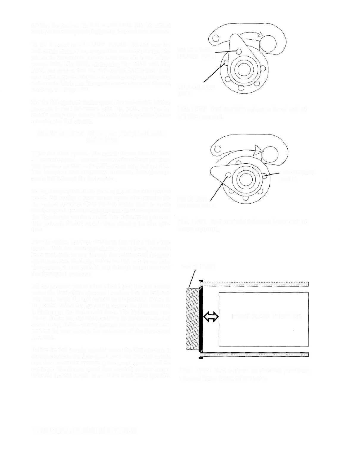
Check at the fastest shutter speed. Hold the lens opening to
a light source and watch through the back of the focal-plane
aperture. When you release the shutter, make sure that you're
getting an exposure all the way across the aperture. If you
get an exposure at one side of the aperture—but not at the
other side—the 2nd curtain is catching the 1st curtain.
For example, consider in Fig. FP25 that the curtains are
traveling from right to left. And you get the result shown in
Fig. FP25—exposure at the right side of the aperture, but
nothing at the left side. The 2nd curtain is catching the 1st
curtain—in Fig. FP25, the 2nd curtain catches the 1st curtain around half way across the aperture.
If you get light all the way across the aperture, you at least
know that the slit isn't closing. But you still don't know if
the curtains are traveling at uniform speeds. The fluorescent light source gives you a better indication. In Fig. ,
notice that the three light slits are the same width—that
means the curtains are traveling at the same speed. If the
light slits are uneven in width, the curtains are traveling at
different speeds.
FIG. FP25 Results of the 2nd curtain
overtaking the 1st curtain—curtain travel is
from right to left.
SETSCREWS
WORM GEARS
But the best way to check curtain speeds is with a commercial shutter-speed tester. Most shutter-speed testers provide
a function for measuring the curtain speeds—the curtaintravel time. The shutter-speed tester may show you both
curtain-travel times simultaneously. You can then check to
see that the travel times are the same. The readings of the
travel times are in milliseconds.
Camera manufacturers now provide specifications for the
curtain-travel times. For example, the manufacturer may
specify 12ms as the curtain-travel time for a particular
model. Both curtains should then cross the focal-plane ap-
erture in 12ms. But it's more critical that both curtains are
traveling at the same speed—even if that speed doesn't exactly match the manufacturer's specification.
You'll usually find the curtain-tension adjustments at the
bottom of the camera, Fig. FP26. The camera in Fig. FP26
uses worm-gear adjustments. To adjust the curtain travel
time, you first loosen the locking setscrew at the top of the
worm housing. You then turn the worm—and the worm turns
the worm gear to increase or decrease the spring tension of
the tension (take-up) roller.
Other focal-plane shutters may use ratchet gears to set the
curtain-travel times In Fig. FP27, you can turn the ratchet
gear freely in one direction—the direction that adds tension. To let off tension, hold the ratchet gear and disengage
the locking spring. Allow the tension-roller spring to unwind slightly.
1st-CURTAIN 2nd-CURTAIN
ADJUST ADJUST
FIG. FP26 Bottom of Nikon F.
The curtain-adjustment positions in Fig. FP26 and FP27
are typical of focal-plane shutters—the 2nd-curtain adjustment is closer to the back of the camera. So, if the 2nd
curtain is catching up with the 1st curtain, you can add
tension to the 1st curtain—the 1st curtain then travels faster.
You could get the same results by letting off some of the
tension from the 2nd curtain. However, a curtain tends to
slow down as the camera ages due to spring fatigue. If the
2nd curtain is catching the 1st curtain, then, it's more likely
that the 1st curtain is traveling too slowly.
118/FOCAL-PLANE SHUTTERS
Page 12

If you have a way to actually measure the curtain-travel
times, you can set the curtains according to the
manufacturer's specifications. For example, if the manufacturer specifies 12ms, adjust each curtain to travel at 12ms.
ADJUSTING SHUTTER SPEEDS WITH
THE FOCAL-PLANE SHUTTER
he curtain tensions do affect the shutter-speed accu
racy—the faster the curtains travel, the faster the expo-
T
sure time. But the slit width has a greater effect on the exposure time.
Most of the old focal-plane shutters provide an adjustment
on the 2nd-curtain latch, Fig. FP28. The adjustment—usually an eccentric—determines when the 1st curtain releases
the 2nd curtain. The sooner the 1st curtain releases the 2nd
curtain, the narrower the slit—and the faster the exposure
time.
The adjustment for the slow speeds is on the slow-speed
governor. An eccentric or screw adjustment increases or
decreases the retard-lever engagement. If you increase the
retard-lever engagement, it takes longer for the 2nd curtain
to run through the slow-speed governor—a slower shutter
speed.
There may also be an adjustment on the pallet engagement.
The adjustment for the pallet engagement may affect I second, 1/2 second, and 1/4 second. You would then use the
retard-lever adjustment for 1/30 second. And use the pallet
adjustment for the three slowest shutter speeds.
FRONT OF CAMERA
1st-CURTAIN
RATCHET
2nd-CURTAIN
RATCHET
LOCKING
SPRINGS
FIG. FP27 Bottom of camera with ratchet-
type adjustments.
ECCENTRIC ON 2nd-CURTAIN LATCH
FIG. FP28 Top of drum-type focal-plane
RETARD ECCENTRIC
PALLET ECCENTRIC
shutter.
FIG. FP29 The slow-speed governor is at the top, release-button end of the Minolta SR-T
101, a classic with a double-roller focal-plane shutter.
FOCAL-PLANE SHUTTERS/119
Page 13

MAKING AND REPLACING SHUTTER
CURTAINS
Removing the old curtains—
With old cameras, you'll frequently find that the curtains
have deteriorated. Curtains may have a rubber-like coaling
on one side. The rubber-like material deteriorates with age,
falling away in flakes.
Or you may find pin holes in the curtain. If you then hold
the curtain to a light source, you'll see light passing through
the curtain in several places. You may even find that the
curtain has torn loose from the bar.
If the camera won't be used to take pictures, curtain damage may not be a problem. But damaged curtains do detract
from the "perfection" of the camera—often a factor with
collectors.
You probably won't be able to purchase replacement curtains. So, if you want to restore the camera to mint condition, you'll have to make new curtains.
SCRIBE
2nd
curtain
FIG. FP30 Front view of the curtain drum.
Some companies do still provide curtain material—bulk
material from which you can cut new curtains. Curtain
material may be rubberized on one side. Or there may be
no rubber-like coating. But you want to use a material that
matches the original curtain.
Curtains aren't especially difficult to make. The problem is
that you have to almost completely disassemble the camera
to replace the curtains—a major job. You probably should
not attempt such a restoration until you're intimately familiar with the particular camera.
Disassemble the camera far enough to reach the rollers—it
may not be necessary to remove the rollers from the body.
However, in some cameras, the position at which the. curtains cement to the rollers or drum is critical—the position
at which you cement the curtain and tapes may be your
only adjustment for the curtain positions. With other cameras, you can adjust the curtain positions by adjusting gear
timing.
If the camera has a drum-type focal-plane shutter, you can
be certain that the curtain positions are critical—both the
position at which the curtain cements to the inner drum and
the positions at which the tapes cement to the outer drum,
Fig. FP30. The positions may also be critical in the doubleroller design. But with many double-roller designs, you can
change the gear timing to adjust the curtain positions.
Fig. FP31 shows the critical timing on the 2nd curtain—the
distance between the curtain bar and the lead edge of
the focal-plane aperture when the 2nd curtain is latched
in the open position. The critical timing on the 1st curtain is the curtain overlap—how far the curtains overlap
one another during the cocking cycle. Typically, the overlap is one bar. But that's not always the case.
inside of the focal-plane aperture to note the edge of the
2nd-curtain bar, Fig. FP31.
Check the curtain overlap during the cocking stroke. Advance the curtains until they are around half way across the
aperture. Then make a note of the overlap.
Also make careful notes and sketches of the curtain positions. Does the rubberized side face the front or the back of
the camera? Which curtain sits to the front of the camera—
the 1st curtain or the 2nd curtain? You might also mark the
old curtains to note which is the 1st curtain and which is
the 2nd curtain—depending on the camera, the two curtains may be identical or slightly different.
You can now let off the curtain tensions. But count the turns
as you let off the tension. You then have a starting point for
reassembly.
2nd CURTAIN
SCRIBE HERE
FOCAL-PLANE APERTURE
It helps to check both timing points before you remove the
curtains. Hold open the shutter on bulb. Then scribe the
120/FOCAL-PLANE SHUTTERS
FIG. FP31 2nd curtain in latched position,
viewed from front of camera.
Page 14

For example, with the design shown in Fig. FP26, use your
screwdriver to hold the ratchet gear in place. Then hold the
lock spring away from the ratchet gear. Allow (he ratchet
gear to rotate slowly clockwise as you count the turns of
initial tension.
With the worm-gear design, Fig. FP25, loosen the setscrew
that locks the worm. Hold the worm gear in place with your
screwdriver. Now push the worm out of its housing. Count
the turns on the worm gear as the tension-roller spring un-
winds.
The starting positions of the curtain and tapes on the ten-
sion rollers aren't critical—there's no timing on the tension
rollers. But it's very critical that the curtain and tapes are
square to the tension rollers. If they aren't square to the
rollers, the slit will be tapered as it moves across the aperture, Fig. FP32. In Fig. FP32, the top of the film frame
receives more exposure than the bottom of the film frame.
You can use a straightedge to scribe the tension rollers—
use the scribe line to align the end of the 1st curtain and to
make sure both 2nd-curtain tapes start at the same position.
Or you can scribe the old lst-curtain edge and the old 2ndcurtain tapes before you remove them. Then peel the 1st
curtain and the 2nd-curtain tapes from the tension rollers.
FIG. FP32 Tapered slit resulting from one
curtain not being square to its roller.
Also scribe the positions of the old curtains and tapes before you remove them from the drum. With some drum designs, you can see the edge of the 2nd curtain, Fig. FP30,
with the shutter released—scribe the center drum along the
2nd-curtain edge. You can normally see the 2nd-curtain edge
in shutters that use titanium (metal) curtains.
But with drum-type shutters using cloth curtains, the 2nd
curtain usually wraps over the edge. Reaching the edge of
the 2nd curtain may then require that you remove the drum—
something you want to avoid if possible. Fortunately, there's
a shortcut you can use. Here's the shortcut:
First pec) the curtain and tapes from the tension rollers.
Then, with the shutter in the released position, place a
straightedge against the 2nd curtain and the drum—at
the position of the 2nd-curtain edge in Fig. FP30). Using
a sharp hobbyist knife, cut the 2nd curtain along the
straight edge.
Work from the cut to peel the 2nd curtain from the drum.
You can now remove the 2nd curtain from the camera.
But the end of the 2nd curtain remains cemented to the
drum—leave this material in place.
Use the 2nd curtain you just removed as a pattern. Cut
the replacement 2nd curtain to the same length. You can
then slide the replacement 2nd curtain around the hack
of the drum, Fig. FP30. Bring the end of the replacement 2nd curtain against the cut end of the 2nd curtain
that remains on the drum—that end of the old 2nd curtain serves as your scribe line.
You also want to scribe the ends of the lst-curtain tapes,
Fig. FP30. But you won't be able to reach the ends without
FIG. FP33 FIG. FP34
unwrapping the tapes from the outer drum.
With the 1st curtain peeled loose from its tension roller,
you can unwrap the tapes. Or you can use the same technique as described for cutting the 2nd curtain—cut the old
tapes and leave the ends cemented to the center drum. Be
sure to cut the new tapes to the same lengths as the tapes
remaining on the old 2nd curtain.
You may not have to scribe the old curtains in a doubleroller design. If you can remove the wind gears (the gears
that engage the winding-roller pinions), you can adjust the
curtain timing—regardless of the starting position of the
curtains. But if you can't remove the wind gears, scribe the
2nd-curtain winding roller to note the lead edge of the 2nd
curtain. Scribe the lst-curtain winding roller to note the
lead edge of each lst-curtain tape.
The scribe marks are useful even if the curtain positions
aren't critical. As mentioned earlier, you can often adjust
gear timing to correct the curtain positions. But you still
want to make sure that the 2nd curtain is square to its winding roller. And the end of each lst-curtain tape must be on
a straight line. If a curtain isn't square to the winding rollers, the curtain will sit at an angle as shown in Fig. FP32.
Making the curtains—
If possible, try to save the old curtain bars—just so you
don't have to make new bars. Each curtain bar may be shaped
similar to the one in Fig. FP33. The end of the curtain then
fits inside the bar. And the bar is pressed closed to sandwich the curtain.
FOCAL-PLANE SHUTTERS/121
Page 15
Here the manufacturer cements the end of the curtain to the
bar. The bar is then pressed closed. Dimples may be added
to the bar—punch marks into both the bar and the curtain—
for added strength.
Carefully spread the bar, Fig. FP33, to free the curtain— Also be very critical when you cement the curtains to the
remember, you're going to reuse the bar. Then peel the old bars—the curtains must be square to the bars. If the curcurtain from the bar. You can now measure the curtain— tains aren't square, the slit will be tapered as it moves across
the length and the width. the aperture, Fig. FP32.
cuts as square, clean, and straight as possible. Use a sharp
knife such as a new single-edged razor blade or a hobbyist
knife. If the knife isn't sharp, the edges of your curtains
may be frayed.
Or the curtain bar may be shaped like the one in Fig. FP34
The curtain and the tapes fold over the bar, Fig. FP35 and
Fig. FP36.
The manufacturer cements the curtain to the bar. A row of
stitches may then be added along the bar—at the position
shown by the dashed line in Fig. FP36—for additional
strength.
Before you peel the curtain from the bar, make careful
measurements—the width of the curtain and the length of
the curtain measured from the edge of the bar. When you
cut the new curtain, leave sufficient material for the fold,
Fig. FP35. But it's the length of the curtain measured from
the bar that's critical.
Now check the curtain material. If you're using the rubber-
ized curtain material, you'll find that the material will stretch
in one direction but not in the other direction. Make your
lengthwise cuts in the direction that the material will not
stretch. Remember that the curtains are pulled from the ends.
If they can stretch in the lengthwise direction, their lengths
will change when tension is applied.
Be very critical as you cut the material—make the curtain
With the type of curtain shown in Fig. FP36, apply Pliobond
both to the curtain and to (the bar. Then fold the curtain over
the bar—make sure the length of the curtain from the edge
of the bar matches your original measurement. While the
cement is drying, make precise adjustments on the curtains—remember, the curtains must be 90° to the bars.
Then, after the cement dries, hand sew the curtains, Fig.
FP36—keep the stitches very close to the bars,
The curtain tape also comes in bulk form—a roll from
which you can cut off the length you need. Be just as critical in matching the lengths of the tapes to those of the old
curtains—especially if the shutter provides no adjustments
for curtain positions.
Installing the curtains—
If you're installing the curtains on a drum, Fig. FP30, remember that the 2nd curtain and the lst-curtain tapes must
align with the scribe lines—or with the cut ends of the curtain and tapes remaining on the drum. Slide the 2nd curtain behind the drum. Bring the end of the 2nd curtain to
the scribe line.
Apply a smooth coat of Pliobond both the back of the cur-
tain and to the front of the center drum. Cementing both
surfaces {contact cementing) strengthens the bond. You can
determine how much of the curtain should be cemented by
examining the old curtain. In general, the cement should
extend around 1/4" from the end of the curtain.
FOLD
FIG. FP35
STITCHES
FIG. FP36
122/FOCAL-PLANE SHUTTERS
Line up the 2nd curtain with your scribe line or the end of
the original curtain and cement the curtain in place. Pliobond
gives you a little time to shift the curtain position before
the cement dries.
The lst-curtain tapes may wrap twice around the end sec-
tions of the drum. If you completely removed the tapes of
the old curtain, wrap the new tapes around the outer drum—
leave the tapes loose so you can reach the ends. Align the
Page 16

tape ends with your scribes and cement them to the outer
drum.
If you left the ends of the old tapes on the drum, you don't
have to wrap the tapes twice around the drum ends—just
bring the ends of the new tapes against the cut ends of the
old tapes.
You can determine if the curtains are in their proper positions before you cement them to the tension rollers. Let the
cement dry for a few minutes. Then hold both curtains toward the tension-roller end of the camera—apply just
enough pressure to remove the slack from the curtain and
tapes. Then slowly cock the shutter. The drum turns, wrapping on the curtains.
As the curtains move to the cocked position, they should
overlap—the overlap should be the amount you noted be-
fore removing the curtains (normally one bar). If there's a
space gap between the curtain bars, you probably didn't
wrap the lst-curtain tapes enough times around the drum
ends. But if the overlap is excessive, you may have wrapped
the tapes loo many times around the drum ends.
Next route the 1st curtain and the 2nd-curtain tapes to the
tension rollers. Follow the same procedures to cement the
curtain and tapes. Here the starting positions aren't critical.
But it's very critical that the curtains are square to the ten-
sion rollers.
After the cement dries, you can put a couple of turns of
tension on the tension rollers—just enough tension to draw
the curtains taut. You can now check the curtain alignment
to see if the curtains are square to their rollers.
Look from the back of the focal-plane aperture as you turn
the center drum in the winding direction—you're now winding on the 2nd curtain. When the 2nd curtain enters the
aperture, you can judge if it's straight, Fig. FP37. Use the
end of the focal-plane aperture as a straight edge.
FIG. FP37 Here the 2nd curtain is square to
the roller.
FIG. FP38 The 2nd curtain is not square to
the roller—the upper end of the curtain must
be pulled from right to left.
around the 2nd-curtain tension roller to hold your tape
"shim" in place.
The extra chunk of tape increases the diameter of the tension roller at the top end. The result—the top end of the
curtain is pulled a little further toward the tension rollers.
Use a similar technique to determine if the 1st curtain is
straight. Cock the shutter. Then hold the drum and release
the shutter. Allow the drum to turn slowly until the 1st cur-
tain to just enter the aperture. Again use the end of the aperture as a straight edge to determine if the 1st curtain is
straight.
If a curtain isn't square, you may be able to make a correc-
tion without removing and recementing that curtain—unless the error is severe. For a slight error, you can use extra
curtain tape to "shim" the curtain.
For example, suppose you're looking at the hack of the
focal-plane aperture. And you can see that the 2nd curtain
isn't quite square—you need to move the upper end of the
curtain toward the tension rollers, Fig. FP38.
Unwrap the upper end of the 2nd-curtain tape from the end
of the tension roller—just enough so you can reach the tape
end. Now insert a small section of tape at the end of the
upper 2nd-curtain tape. Allow the 2nd-curtain tape to wrap
Again check the alignment of the 2nd curtain. If the 2nd
curtain is now straight, your tape "shim" is the right size.
But you may decide you need a slightly larger shim—or a
slightly smaller shim. Once you've determined the proper
size, cement your tape shim to the tension roller.
If the 1st curtain isn't straight, you can use a similar shimming procedure—but this time, shim the lst-curtain tapes
where the tapes cement to the drum ends.
ADJUSTING CURTAIN TIMING
We mentioned that many double-roller designs allow you
to adjust the curtain timing. The upper ends of the winding
rollers engage the winding gears—the gears that rotate to
wind on the curtains. If you can change the timing of these
wind gears, you can adjust the curtain positions.
First adjust the timing of the 2nd-curtain wind gear—the
gear that turns the 2nd-curtain winding roller. Remember
FOCAL-PLANE SHUTTERS/123
Page 17

that the 2nd-curtain latch should hold the 2nd curtain in a
certain position—the curtain bar should be a certain distance from the lead edge of the focal-plane aperture. You
noted that distance before removing the curtains. Many
cameras have factory scribe marks to note the 2nd-curtain
position.
Wind on the 2nd curtain to the cocked position. And engage the 2nd-curtain latch with the 2nd-curtain wind gear.
Now check the position of the 2nd curtain—the lead edge
of the 2nd-curtain bar should be aligned with the scribe
mark. Change the timing between the 2nd-curtain wind gear
and the 2nd-curtain winding roller until the curtain is in the
proper position.
2nd-CURTAIN
WIND GEAR
PINION ON
TOP OF 2ndCURTAIN
WINDING
ROLLER
Adjust the timing of the 1st curtain for the proper overlap.
Start with both curtains in the released position. Then slowly
cock the shutter. Check the curtain overlap as the curtains
move to the cocked position. If the overlap isn't right, change
the timing between the lst-curtain wind gear and the lstcurtain winding roller.
For example, Fig. FP39 and Fig FP40 show the sequence
in an early Pentax double-roller design, the H3v. The lstcurtain wind gear sits on top of the 2nd-curtain wind gear.
You would then first install the 2nd-curtain wind gear, Fig.
FP39. Wind on the 2nd curtain to the charged position. And
engage the 2nd-curtain wind gear with the 2nd-curtain latch.,
Fig. FP39. Now adjust the timing between the 2nd-curtain
wind gear and the 2nd-curtain winding roller until the cur-
tain is held the proper distance from the focal-plane aper-
ture, Fig. FP31.
Disengage the 2nd-curtain latch to release the 2nd curtain.
Then install the lst-curtain wind gear, Fig. FP40. As you
2ndCURTAIN
LATCH
FIG. FP39 Adjusting the timing of the 2nd
curtain.
turn the lst-curtain wind gear, the lst-curtain wind gear
turns the 2nd-curtain wind gear. Both curtains travel simultaneously to the cocked position.
Turn the 1st-curtain wind gear until the two curtains are
around half way across the aperture. Then check the curtain overlap. In the Pentax, the curtains should overlap by
one bar—one curtain bar sits directly in front of the other
curtain bar. Adjust the overlap by changing the timing between the lst-curtain wind gear and the lst-curtain wind-
ing roller.
1st-CURTAIN WIND
GEAR
FIG. FP40 Adjusting the timing of the 1st curtain.
124/FOCAL-PLANE SHUTTERS
PINION ON TOP OF
1st-CURTAIN
WINDING ROLLER
 Loading...