

Page 1

PENTAX VIDEO PROCESSOR
PENTAX VIDEO PROCESSOR
OWNER’S MANUAL
1
2
Generic name: Light source processor for endoscopes
Medical equipment requiring controls/designated medical equipment requiring controls
Page 2

2
INTENDED USE:
This electro-medical device (Video Processor) is intended to be used for endoscopic diagnosis and treatment.
Together, this Video Processor and PENTAX video endoscope may provide optical visualization of, and/or
therapeutic access to, various body cavities, organs and canals. Do not use this device for any purpose other than
that for which it has been designed.
This device should only be used by physicians who have thoroughly studied all the characteristics of this device
and who are familiar with the proper techniques of endoscopic examination.
J Compatible Endoscope Models
This processor can be used with
- PENTAX color video endoscopes (K-series) except 30K, 40K, 70CIMK/CIFK/CILK (Confocal Endomicroscopes) and
70UK/UTK/URK (Ultrasound Endoscopes) series
- PENTAX fiberscopes with use of PENTAX video adapter module PVK-1070 and PVK-1070Z
IMPORTANT:
Read this manual before operating and save this book for future reference.
This manual describes the recommended procedures for inspecting and preparing the EPK-p Video Processor
prior to its use and the care and maintenance after its use. It does not describe how an actual procedure is to be
performed, nor does it attempt to teach the beginner the proper technique or any medical aspects regarding the
use of the equipment.
Failure to follow the instructions in this manual may result in damage to and/or malfunction of the equipment.
Do not use this device for any other purpose than that for which it has been designed.
If you have any questions regarding any of the information in this manual or concerns pertaining to the safety
and/or use of this equipment, please contact your local PENTAX representative.
CAUTION:
Federal (USA) law restricts this device to sale by, or on the order of a physician or other appropriately licensed
medical professional.
Before Using This Device
Symbol for “MANUFACTURER”
Symbol for “DATE OF MANUFACTURE”
Symbol for “AUTHORISED REPRESENTATIVE
IN THE EUROPEAN UNION”
The CE marking assures that this product complies with the requirements of the EC directive for safety.
Das CE Zeichen garantiert, daß dieses Produkt die in der EU erforderlichen Sicherheitsbestimmungen
erfüllt.
Le logo CE certifie que ce produit est conforme aux normes de sécurité prévues par la Communauté
Européenne.
II marchio CE assicura che questo prodotto è conforme alle direttive CE relative alla sicurezza.
La marca CE asegura que este producto cumple todas las directivas de seguridad de la CE.
Page 3

3
Contents
Before Using This Device................................................................................................. 2
1 Names and Functions of Parts 10
Main Unit ........................................................................................................................10
Front Panel .....................................................................................................................11
Rear Panel......................................................................................................................12
Water Bottle (OS-H4) ..................................................................................................... 13
2 Preparation 14
System Configuration .....................................................................................................14
Installation ...................................................................................................................... 15
Connecting an Endoscope .............................................................................................18
3 Pre-use Inspections 20
Power and Lamp Inspection ...........................................................................................20
Automatic Brightness Control Inspection........................................................................21
Scope Control Buttons Inspection .................................................................................. 21
Inspection of Operation Panel Buttons ...........................................................................21
Air/Water Supply Inspection ...........................................................................................22
Color Tone Inspection .................................................................................................... 22
Suction Inspection ..........................................................................................................23
4 Operating Procedure 24
Turning On/Off the Processor.........................................................................................24
Monitor Screens .............................................................................................................24
Front Panel Operations ..................................................................................................25
Keyboard Operations......................................................................................................28
5 Maintenance and Storage 42
After Use Care and Storage ...........................................................................................42
Care and Storage of the Water Bottle Set......................................................................43
Replacing the Lamp........................................................................................................44
Replacing the Fuses.......................................................................................................46
Repair .............................................................................................................................47
6 Troubleshooting 48
7 Specifications 50
8 Electromagnetic Compatibility 51
9Appendix 54
Default Settings .............................................................................................................. 54
Page 4

4
1. SAFETY PRECAUTIONS - IMPORTANT
The following precautions should always be exercised with the use of all electro-medical equipment to ensure
safety to all involved parties - user(s), patient(s), etc.
Please carefully read and follow this owner’s manual.
1-1. TRAINING
This equipment should only be used under the supervision of a trained physician in a medical facility. Do not use
in other locations or for any other purposes than the intended application.
1-2. INSTALLATION
1. This equipment should NEVER be installed or used in areas where the unit could get wet or be exposed to any
environmental conditions such as high temperature, humidity, direct sunlight, dust, salt, etc., which could
adversely affect the equipment.
2. This equipment should NEVER be installed or used in the presence of flammable or explosive gases or
chemicals.
3. This equipment should NEVER be installed, used or transported in an inclined position nor should it be
subjected to impact or vibration.
4. For safety reasons, this equipment must be properly grounded. (This equipment should be connected to a
three (3) prong hospital grade receptacle in U.S.A. or Canada.)
5. Ensure that all power requirements are met and conform to those specified on the rating plate located on the
rear panel.
6. Do not block the air intake vent of this equipment.
7. Do not allow the power cord to become twisted, crushed or pulled taut.
8. When using an isolation transformer for any ancillary equipment, ensure the power requirements of the devices
do not exceed the capacity of the isolation transformer. For further information, contact your local PENTAX
distributor.
1-3. PRIOR TO USE
1. Confirm that this equipment functions properly and check the operation of all switches, indicators, etc.
2. To prevent electrical shock when used with endoscopes, this equipment is insulated (type BF electro-medical
equipment). Do not allow it to be grounded to other electrical devices being used on the patient. Rubber gloves
should always be worn to prevent grounding through user(s).
3. Confirm that other devices used in conjunction with this equipment function properly and that these other
devices will not adversely affect the operation or safety of this equipment. If any component of the endoscopic
system is not properly functioning, the procedure should not be performed.
4. Check and confirm that all cords or cables are connected correctly and securely.
5. The lamp life when used in this equipment is on average 50 hours. Prior to use, check the lamp life indicator
on the front panel to ensure the indicator is lit green.
NOTE
The lamp life for the EPK-p processor is rated at 50 hours.
Page 5

5
1-4. DURING USE
1. To prevent electric shock, the endoscope and/or any other ancillary device should NEVER be applied directly
to the heart.
2. Make sure that no contact is made between the patient and this equipment.
3. To avoid damage to the luminous display and flat membrane switches, do not press any keys with any sharp
or pointed objects.
4. The light emitted by the Xenon lamp is extremely intense. Avoid looking directly at the light exiting the
endoscope and/or this equipment.
5. To protect the users eyes and avoid risk of thermal injury during an endoscopic examination, use only the
minimum amount of brightness required.
6. During clinical procedures, avoid unnecessary prolonged use which could compromise patient/user safety.
7. Continually monitor this equipment and the patient for any signs of irregularities.
8. In the event that some type of irregularity is noted to the patient or this equipment, take the appropriate action
to ensure patient safety.
9. If the operation of any of the components of the endoscopic system fails during the procedure and the
visualization of the procedure is lost or compromised, place the endoscope in the neutral position and slowly
withdraw the endoscope.
10. This equipment should only be used according to the instruction and operating conditions described in this
manual. Failure to do so could result in compromised safety, equipment malfunction or instrument damage.
1-5. AFTER USE
1. Refer to the operating instructions supplied with all the components of the endoscopic system to establish the
right order in which components should be turned off. Some peripheral devices may have to be turned off first
to avoid compromising their operation.
2. Wipe all surfaces with gauze slightly dampened with alcohol.
3. Be sure connector interfaces and ventilation ports are not allowed to become wet or splashed with liquids.
1-6. STORAGE
1. This equipment should NEVER be stored in areas where the unit could get wet or be exposed to any
environmental conditions such as high temperature, humidity, direct sunlight, dust, salt, etc., which could
adversely affect the equipment.
2. This equipment should NEVER be stored in the presence of flammable or explosive gases or chemicals.
3. This equipment should NEVER be stored or transported in an inclined position, nor should it be subjected to
impact or vibration.
4. Cords, accessories, etc., should be cleaned and neatly stored.
5. This equipment should be maintained in a clean condition during storage and be ready for subsequent use.
1-7. SERVICE
1. Alterations/modifications to the equipment should NEVER be made. Repairs should only be performed by an
authorized PENTAX service facility.
2. When replacing the lamp, use only the lamp recommended by PENTAX and follow all PENTAX instructions
provided.
1-8. MAINTENANCE
1. Periodically this equipment and any applicable accessories should be inspected for operation and safety.
1-9. DISPOSAL
1. The equipment should be returned for disposal to PENTAX.
Contact your local PENTAX representative or service facility.
1-10. FOR THE STATE OF CALIFORNIA, USA ONLY
Perchlorate Material-special handling may apply. See www.dtsc.ca.gov/hazardouswaste/perchlorate.
Perchlorate Material: Lithium battery contains perchlorate.
Information on Disposal for users in the European Union
This product is a medical device. In accordance with European Directive 2002/96/EC on Waste Electrical and
Electronic Equipment, this symbol indicates that the product must not be disposed of as unsorted waste, but
should be collected separately. Contact your local PENTAX distributor for correct disposal and recycling.
By disposing of this product correctly, you will help ensure that the waste undergoes necessary treatment,
recovery and recycling, thus preventing potential negative effects on the environment and human health which
could otherwise arise due to inappropriate waste handling.
Page 6

6
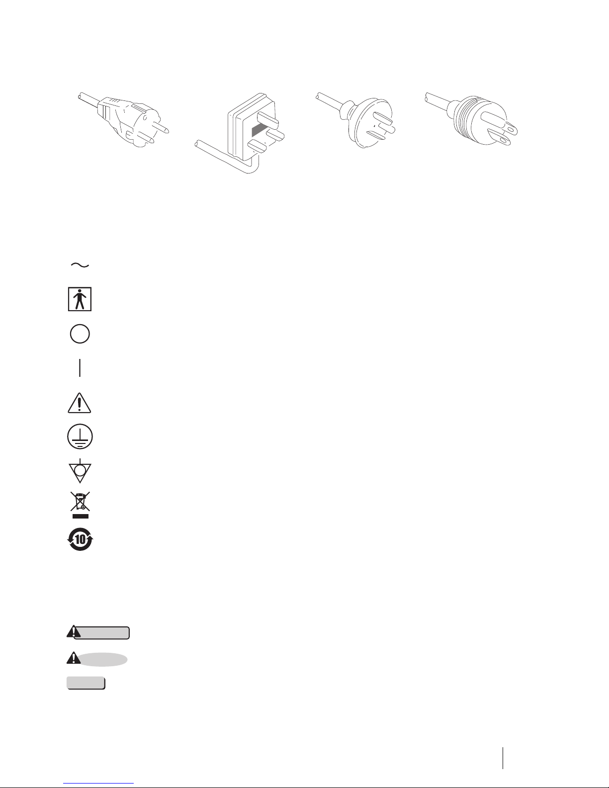
POWER REQUIREMENTS
Check the standard power plug configurations that are used in your country. If the appropriate power cord is not
included in your product, notify your local PENTAX distributor.
SYMBOLS ON MARKING
CONVENTIONS
The following conventions have been established in the text of this manual to aid in the identification of potential
hazards of operation;
Continental Europe
(Use a SEV approved plug
for Switzerland)
U.K. Australia and
New Zealand
U.S.A. and Canada
(Hospital Grade)
Alternating current
Type BF applied part (Safety degree specified by IEC 60601-1)
OFF (Power: disconnection from mains)
ON (Power: connection to the mains)
Attention, consult Owner’s Manual
Protective earth (ground)
Equipotentiality
Waste in Electrical and Electronic Equipment
China RoHS
: Could result in death or serious injury.
: May result in minor or moderate injury or property-damage.
: May result in property-damage. Also, advises owner/operator about important information on the use of
this equipment.
WARNING
CAUTION
NOTE
Page 7

7
1. PRECAUTIONS DE SECURITE - IMPORTANT
Les précautions suivantes doivent toujours être observées lors de l’utilisation de tout matériel médical électrique
susceptible d’être utilisé avec cet appareil, pour assurer à toutes les personnes concernées (utilisateus, patients,
etc...) une sécurité maximale.
Veuillez lire et suivre attentivement les recommandations du manuel d’utilisation.
1-1. FORMATION
L’appareil ne doit être utilisé que sous la surveillance d’un médecin expérimenté, dans un établissement médical.
Ne pas utiliser dans un autre endroit ou pour toute autre application pour laquelle il n’est pas prévu.
1-2. INSTALLATION
1. L’appareil ne doit JAMAIS être placé ou utilisé dans un endroit où il serait mouillé ou exposé à l’humidité, à
une température élevée, à la lumière solaire directe, à la poussière, au sel, etc., qui pourraient l’endommager.
2. L’appareil ne doit JAMAIS être placé ou utilisé en présence de gaz ou de produits chimiques inflammables ou
explosifs.
3. L’appareil ne doit JAMAIS être placé, utilisé ou transporté en position inclinée, ni être soumis à des chocs ou
des vibrations.
4. Pour des raisons de sécurité, l’appareil doit être correctement relié à la terre (cet appareil doit être branché
dans une prise secteur 3 broches aux normes Hôpital aux U.S.A. et au Canada).
5. Assurez-vous que les spécifications électriques de la prise secteur sont conformes à celles indiquées à
l’arrière de l’appareil.
6. Ne pas obturer les orifices de ventilation de l’appareil.
7. Ne pas écraser, plier ou tendre le cordon secteur.
8. Dans le cas ou un transformateur d’isolement est utilisé pour le matériel périphérique, vérifier que la puissance
totale de l’installation ne dépasse pas la capacité du transformateur. Pour de plus amples informations,
contacter votre distributeur PENTAX.
1-3. AVANT UTILISATION
1. Vérifier le fonctionnement de l’appareil et de ses interrupteurs, afficheurs, voyants, etc...
2. Pour prévenir les risques de chocs électriques lorsqu’il est utilisé avec des endoscopes, cet appareil doit être
installé comme “Matériel électrique médical type BF”. Ne pas le relier aux autres appareils électriques utilisés
pour le même patient. Les utilisateurs doivent s’isoler électriquement en portant des gants de caoutchouc.
3. Vérifier le fonctionnement des périphériques utilisés avec l’appareil et s’assurer qu’ils n’en perturbent pas le
fonctionnement et la sécurité. Si l’une des composantes du système endoscopique ne fonctionne pas
correctement, interrompre l’utilisation.
4. Vérifier le branchement des différents câbles de liasions (vidéo, secteur, contrôle, etc...).
5. La durée de vie nominale de la lampe est de 50 heures en moyenne. Avant utilisation, vérifier que le témoin
de durée de vie vert ou jaune est allumé.
NOTE
La durée de vie de la lampe estimée à 50 heures s’applique au processeur EPK-p.
Page 8

8
1-4. PENDANT L’UTILISATION
1. Pour éviter les risques de choc électrique, l’endoscope et/ou tout autre périphérique utilisé conjointement avec
l’appareil ne doivent JAMAIS être placés directement sur le coeur.
2. Ne pas mettre le patient en contact avec l’appareil.
3. Pour conserver l’afficheur et le clavier souple en bon état, ne pas presser les touches du tableau avec un objet
pointu ou tranchant.
4. Eviter de regarder directement la lumière sortant de l’endoscope et/ou de l’appareil du fait de la forte luminosité
émise par la lampe Xénon.
5. Pour protéger l’utilisateur et éviter toute blessure thermique pendant l’examen, régler la luminosité au
minimum nécessaire.
6. Eviter une utilisation prologée de l’appareil si elle n’est pas indispensable, pour ne pas compromettre la
sécurité du patient et de l’utilisateur.
7. Surveiller en permanence l’appareil et le patient pour prévenir tout signe de dysfonctionnement.
8. En cas de problème avec le patient ou l’appareil, prendre toutes les mesures nécessaires pour préserver la
sécurité du patient.
9. Si un problème de fonctionnement survient sur l’un des appareils du système endoscopique et que l’image est
interrompue ou altérée, placer l’endoscope en position neutre et le retirer doucement.
10.
Cet appareil doit toujours être utilisé selon les instructions et conditions de fonctionnement décrites dans ce
manuel. Ne pas les suivre peut compromettre la sécurité, le fonctionnement du matériel, ou endommager l’appareil.
1-5. APRES UTILISATION
1. Veuillez vous référer aux instructions fournies avec chaque composante du système endoscopique afin
d’éteindre les composantes dans l’ordre adéquat. Certains périphériques peuvent devoir être éteints d’abord
pour ne pas compromettre leur fonctionnement.
2. Essuyer les appareils avec une compresse légèrement imbibée d’alcool.
3. Vérifier que les connecteurs et les orifices de ventilation sont à l’abris des projections de liquides.
1-6. STOCKAGE
1. L’appareil ne doit JAMAIS être rangé à l’humidité, à température élevée, à la lumière solaire directe, la
poussière, au sel, etc., qui pourraient l’endommager.
2. L’appareil ne doit JAMAIS être rangé en présence de gaz ou de produits chimiques explosifs.
3. L’appareil ne doit JAMAIS être rangé en position inclinée ni être soumise à des chocs ou des vibrations.
4. Les accessoires et les câbles doivent être nettoyés et rangés correctement.
5.
L’appareil doit être maintenu en parfait état de propreté durant le stockage, et tenu prêt pour l’utilisation suivante.
1-7. SERVICE
1. Ne JAMAIS modifier ou altérer l’appareil. Les réparations éventuelles ne doivent être effectuées que par un
service après-vente agréé PENTAX.
2. Le remplacement de la lampe ne doit être effectué que par une lampe agréée par PENTAX et en suivant les
instructions fournies par PENTAX.
1-8. MAINTENANCE
1. Périodiquement, cet appareil et tous les périphériques associés doivent être vérifiés en fonctionnement et en
sécurité.
1-9. ÉLIMINATION
1. Ce matériel doit être retourné à PENTAX pour élimination.
Contacter votre représentant ou votre service après-vente PENTAX local.
Information concernant l’élimination des produits dans l’Union européenne
Ce produit est un dispositif médical. En conformité avec la Directive européenne 2002/96/CE relative aux
déchets d’équipements électriques et électroniques, ce symbole indique que le produit ne doit pas être éliminé
comme un déchet non trié, mais qu’il doit faire l’objet d’une collecte sélective. Contactez votre distributeur
PENTAX local pour avoir des informations concernant la procédure correcte d’élimination et de recyclage. En
éliminant ce produit correctement, vous contribuerez à garantir que ce déchet est soumis au traitement, à la
valorisation et au recyclage nécessaires, empêchant ainsi les effets négatifs potentiels pour l’environnement et
la santé des personnes qui résultent de la gestion inappropriée des déchets.
Page 9
9
ALIMENTATION NECESSAIRE
Vérifiez le type de prise de courant utilisé dans votre pays. Si le cordon secteur approprié n’est pas fourni avec
votre appareil, contactez votre distributeur PENTAX.
SYMBOLES UTILISES
CONVENTIONS
Les conventions suivantes ont été adoptées dans le texte de ce manuel, afin d’aider à l’identification des risques
potentiels liés à l’utilisation;
Europe Continentale
(Utiliser une fiche homologuée
SEV pour la Suisse)
Royaume - Uni Australie et Nouvelle Zélande USA et Canada
(Normes Hôpital)
Courant alternatif
Élément type BF (Niveau de sécurité spécifié par la norme IEC60 601-1)
“OFF” (Alimentation : déconnectée du secteur)
“ON” (Alimentation : connectée au secteur)
Attention : consulter le manuel d’utilisation
Mise à la terre de protection
Equipotentialité
Déchets d’équipements électriques et électroniques
RoHS Chine
: Peut causer la mort ou une blessure grave.
: Peut causer une blessure légère à modérée ou des dégâts au matériel.
: Peut causer des dégâts au matériel. Donne aussi à l’utilisateur des informations sur les appareils.
WARNING
CAUTION
NOTE
Page 10
10 Names and Functions of Parts
1
1 Names and Functions of Parts
WARNING
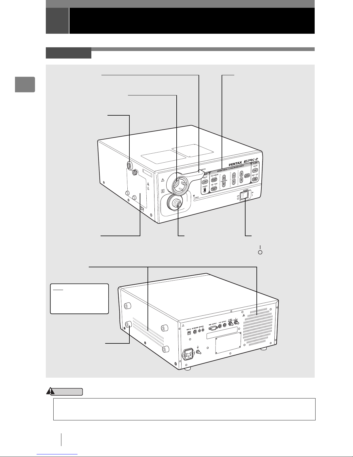
Main Unit
Be sure to turn off the processor before you attach or remove the scope.
The light guide and electrical connector of the scope and the pins may be hot directly after use. Do not touch these parts
and hold a plastic part of the scope when, for example, removing the scope.
Front Panel
I “Front Panel” (P.11)
Power Switch
Turn the power on or off.
side: Power on
side: Power off
Light Guide Attachment
Insert the light guide of a
scope.
Lamp Housing Cover
Open this door when you want to replace a
lamp.
I “Replacing the Lamp” (P.44)
Ventilation Grid
This is a ventilation grid for
the cooling fan.
Note
Install the processor in a
location where the
ventilation grid will not be
blocked.
Scope Locking Lever
Locking/unlocking lever for when you attach or remove a scope.
Endoscope Electrical Connector
Insert the electrical connector of a scope.
Water Bottle Receptacle
Insert the air pipe stem of a water
bottle.
Ventilation Grid Guard
Spacer for preventing the
ventilation grid on the side
from being blocked.
Page 11
Names and Functions of Parts 11
1
CAUTION
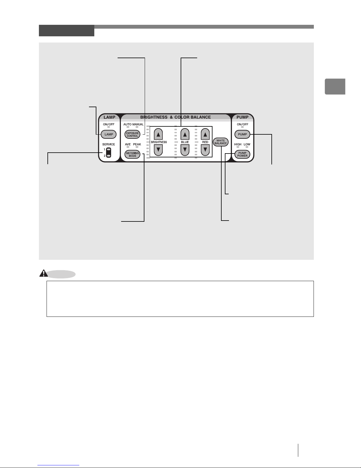
Front Panel
The lamp life for the EPK-p processor is 50 hours. Check the service lamp life indicator on the front panel before you
use the processor. When the lamp needs to be replaced, the service light will illuminate in orange for either service light
1 or 2 and "Please replace lamp (1 or2)" appears on themonitor. Check the service light and correctly identify which lamp
needs to be replaced and replace the appropriate lamp with a new one.
I “Replacing the Lamp” (P.44)
Lamp Switch c
Use this switch to turn
the lamp on or off.
I “Lamp Switch”
(P.25)
Measuring Method Switch d
Use this switch to change the measuring method if you selected [AUTO] with K.
AVE: Measure based on the average brightness value for the whole screen.
PEAK: Measure based on the maximum brightness value for the screen.
I “Measuring Method Switch” (P.26)
Lamp Life Indicator
An indicator lights green when the lamp can be
used. If a lamp goes out, the indicator lights
orange. Replace the lamp.
I “Replacing the Lamp” (P.44)
Exposure Control Switch K
Use this switch to change the method of
adjusting the screen brightness.
AUTO: Adjust the screen brightness
automatically.
MANUAL: Adjust the screen brightness
manually.
I “Exposure Control Switch” (P.26)
Adjustment Switches
If you adjust the brightness and the red and blue color
tone levels of the screen with ab, the levels are
indicated by the indicators.
BRIGHTNESS: Adjust the brightness of the screen.
RED: Adjust the red color tone of the screen.
BLUE: Adjust the blue color tone of the
screen.
I “Adjustment Switches” (P.27)
White Balance Switch N
Adjust the white balance.
I “White Balance Switch” (P.27)
Pump Switch e
Use this switch to turn the pump
on or off.
I “Pump Switch” (P.26)
Pump Power Switch f
Use this switch to set the strength of
the air and water supply of the pump.
I “Pump Power Switch” (P.26)
Page 12
12 Names and Functions of Parts
1
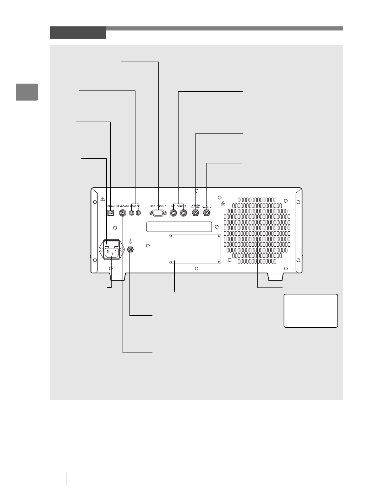
Rear Panel
RGB OUTPUT (Video out)
This connector is for outputting video signals
(RGB color signals and synchronous signals)
to send to a monitor or image processor.
Power Input Socket
Insert the AC power cord.
Y/C OUTPUT
These connectors (separated video
outputs) are for outputting separate video
signals (video signals separated into
luminance signals and color signals) to
send to a monitor or image processor.
VIDEO OUTPUT
This connector is for outputting composite
video signals (BNC connectors) to send to
a monitor or image processor.
Ventilation Grid
Note
Install the processor
in a location where
the ventilation grid
will not be blocked.
Rating Plate
This plate shows the processor rating
specifications, acquired standards, etc.
Potential Equalization Terminal
This terminal is used with a potential
equalization busbar to equalize the
potential of other equipment connected
to the processor.
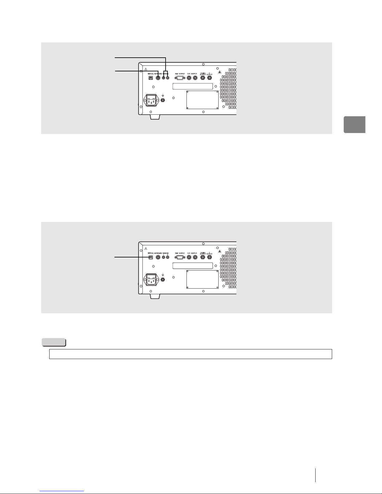
REMOTE
These connectors are for when
you want to remotely operate
peripheral devices.
YOUTPUT
This connector (BNC connector) is for
outputting black and white video signals.
Fuse Box
This fuse box
contains 2 fuses.
I “Replacing the
Fuses” (P.46)
KEYBOARD
This connector is for connecting a
keyboard. You can connect a general
purpose keyboard (US layout).
SERIAL
This connector is for
outputting the digital
data of still images.
Page 13
Names and Functions of Parts 13
1
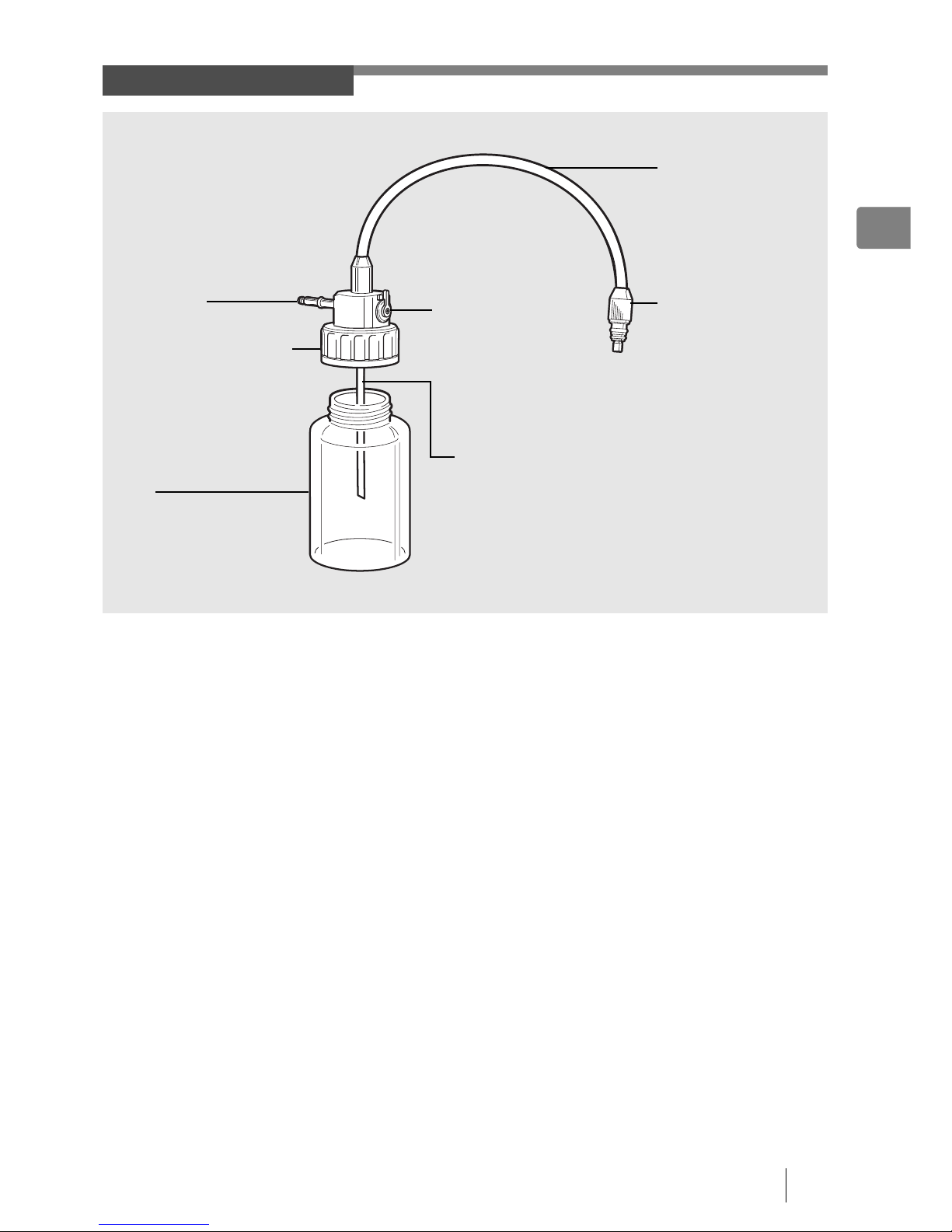
Water Bottle (OS-H4)
Water Feeding Stem
Used for suctioning water from inside the
bottle.
Water Bottle Cap Assembly
Attach this so that no air leaks out.
Bottle
This bottle is for sterile water.
Prior to use, pour sterile water into
the water bottle until it is about two
thirds full.
Air Pipe Stem
Insert this into the processor.
Air/Water Hose
The inside of the hose is
split into two for the air
and water supply.
Air/Water Connector
Connect this to the air/
water supply connector of
the scope.
A/W-DRAIN Lever
Use this to switch between
the air/water supply and
drain. Align the switch to the
A/W position before use.
Page 14
14 Preparation
2
2 Preparation
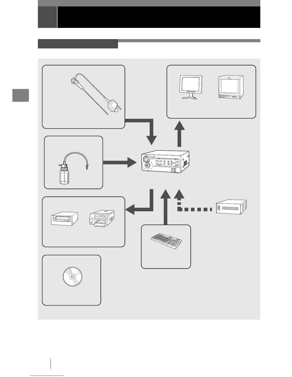
The following shows an example of a system configuration for using the processor.
System Configuration
EPK-p Processor
(This Processor)
Isolation
Transformer
SAT-1300
(HOYA Corporation)
Software
Image Capture Software
OS-I1
(HOYA Corporation)
CRT Monitor
PVM-14M2MDJ
(Sony Corporation)
Keyboard
OS-A35
(HOYA Corporation)
K-Series Scope or Fiberscope
Printer
UP-55MD
(Sony Corporation)
LCD Monitor
OS-M2
(HOYA Corporation)
Display Devices
DVD Recorder
DVO-1000MD
(Sony Corporation)
Recording Devices
Input Devices
I “Compatible Endoscope
Models” (P.2)
Water Bottle OS-H4
(HOYA Corporation)
Page 15
Preparation 15
2
Install the processor and peripheral devices while referring to “System Configuration” (P.14). Install them on a stable and level
surface.
CAUTION
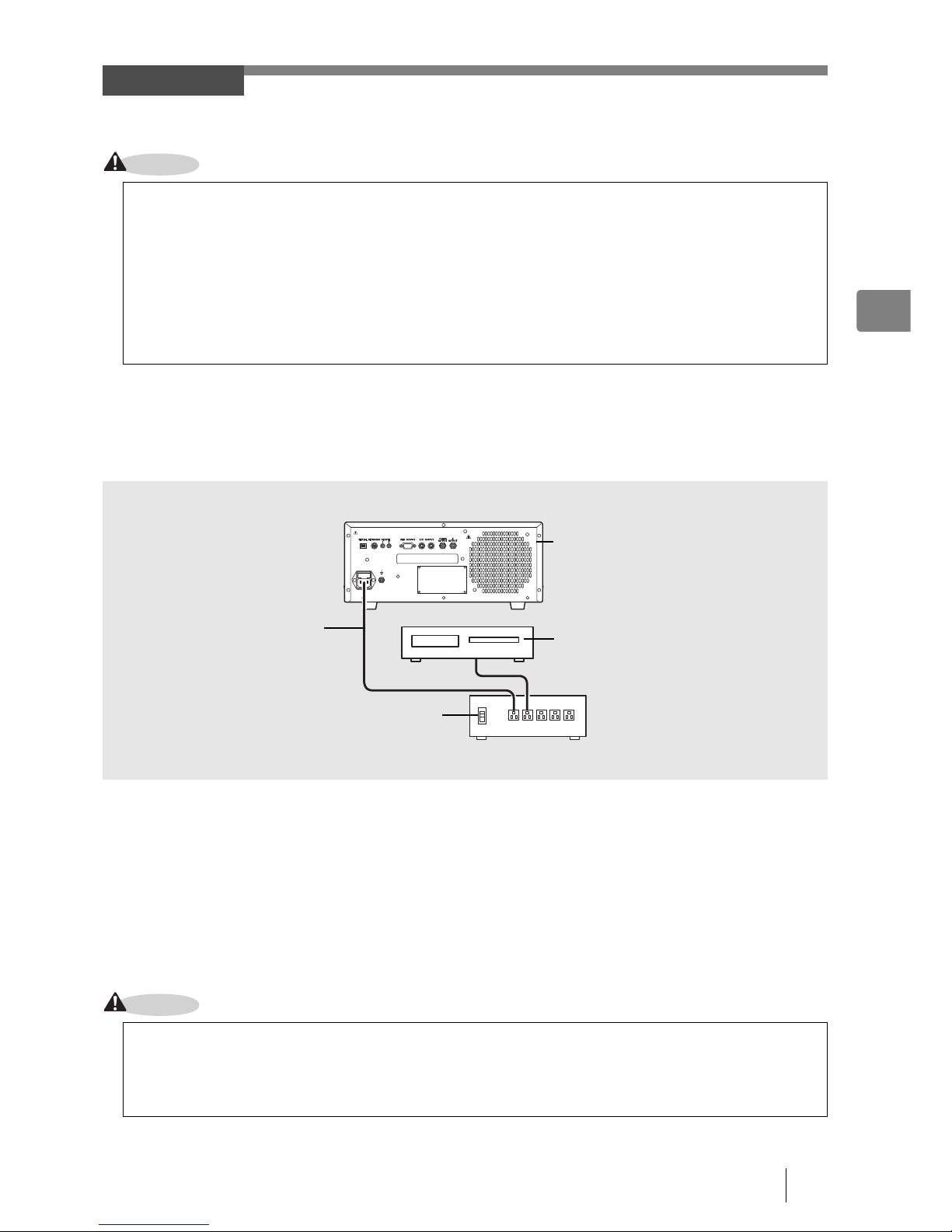
J Connecting an Isolation Transformer
Connect the processor and peripheral devices to an isolation transformer. To reduce the possibility of electric shock connect
the video processor and peripheral devices to the PENTAX SAT-1300 Isolation Transformer or another Medical Grade Isolation
Transformer of the appropriate power rating.
1
Connect the power cord of the isolation transformer to a three-prong power outlet that meets the
power rating indicated on the rating plate.
2
Use the AC power cord to connect the power input socket on the rear panel of the processor to
the isolation transformer.
• Make sure the processor is turned off beforehand.
3
Connect the peripheral devices to the isolation transformer.
• Make sure the peripheral devices are turned off prior to installation.
• For details on peripheral devices, refer to the instruction manuals for the peripheral devices.
CAUTION
Installation
z Do not install the processor in any of the following locations.
- Where the processor is likely to be exposed to water.
- Where flammable or explosive gas is present.
- In very hot and humid locations.
- Where the processor will be exposed to direct sunlight.
z Do not install the processor vertically. Doing so may cause a malfunction or water to leak.
z Install the processor in a location where the ventilation grids will not be blocked.
z Install the processor in a location where dust will not enter inside. Wipe off any dust on the processor. Excessive
amounts of dust accumulating inside the unit may cause the processor to malfunction, emit smoke, or catch fire.
z Do not hold the scope locking lever when you move the processor.
z Do not connect any electrical devices other than the processor and peripheral devices of the processor to the isolation
transformer.
z Make sure the voltage, current, and power consumption of the processor and peripheral devices do not exceed the
maximum ratings indicated on the isolation transformer.
z Be sure to securely connect the power cord of the isolation transformer to a three-prong power outlet.
Isolation Transformer
Processor
Peripheral Device
AC Power Cord
Page 16
16 Preparation
2
J Connecting Peripheral Devices
Connect peripheral devices to the processor. Make sure the processor and peripheral devices are turned off beforehand.
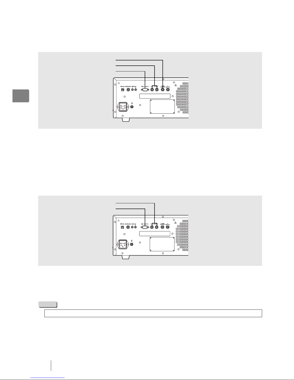
Q Connecting a Monitor
Connect a monitor to the processor. For details, refer to the instruction manual for the monitor.
Connecting a monitor with a composite video input
Use a BNC video cable (OS-A17) to connect the VIDEO OUTPUT to the composite video input of the monitor.
Connecting a monitor with an RGBS video input (BNC)
Use an RGB cable (OS-A25) to connect the RGB OUTPUT to the RGBS video input (BNC) of the monitor.
Connecting a monitor with a 4-pin female mini-DIN connector
Use a Y/C cable (OS-A24) to connect the Y/C OUTPUT to the 4-pin female mini-DIN connector of the monitor.
Q Connecting a Printer
Connect a printer to the processor. For details, refer to the instruction manual for the printer.
For RGB output method
Use an RGB cable (OS-A25) to connect the RGB OUTPUT to the connector of the printer.
For Y/C output method
Use a Y/C cable (OS-A24) to connect the Y/C OUTPUT to the connector of the printer.
NOTE
The BNC cable (OS-A17) and Y/C cable (OS-A25) are sold separately.
VIDEO OUTPUT
Y/C OUTPUT
RGB OUTPUT
Y/C OUTPUT
RGB OUTPUT
Page 17
Preparation 17
2
Q Connecting a Keyboard and Remote Control
For details, refer to the corresponding instruction manuals.
Connecting a keyboard
Connect a general-purpose keyboard (US layout) to the KEYBOARD connector.
• You can also connect a keyboard (OS-A35: sold separately) supplied by PENTAX.
Connecting a remote control
When you want to use a peripheral device that includes support for remote (trigger) input, use a control cable (OS-A58) to
connect the remote connector of the peripheral device to REMOTE. For details on the peripheral device, refer to the instruction
manual for the peripheral device.
Q Connecting a PC
Connect a PC with Image Capture Software (OS-I1) installed to the processor. For details, contact our service personnel.
Connecting a PC
Connect the serial interface of the PC to the SERIAL port.
NOTE
The control cable (OS-A58) and Image Capture Software (OS-I1) are sold separately.
REMOTE
KEYBOARD
SERIAL
Page 18

18 Preparation
2
Connect a scope to the processor. Use a scope with a water bottle and suction unit connected to the scope. You can connect
a PENTAX K-series video endoscope (P.50) to the processor. For details on the scope, refer to the owner’s manual for the
scope.
1
Align the scope locking lever of the processor to the
OPEN position. (Refer to Figure 2.1)
2
Insert the electrical connector and light guide of the
scope into the corresponding scope electrical
connector and light guide attachment of the
processor and move the scope locking lever in the
direction of
2 until it clicks into the LOCK position.
3
Attach water bottle assembly, 2/3 filled with sterile water, to the appropriate location on the left
side of the video processor.
NOTE
• Align the A/W-DRAIN lever to the A/W (air/water supply)
position. (Refer to Figure 2.2)
• Insert the air/water connector into the holder of the cap until the
scope is connected. (Refer to Figure 2.3)
Connecting an Endoscope
z Do not over tighten the cap.
z Replace the sterile water every day.
z Be sure to use sterile water.
1
2
Scope
Locking
Lever
Electrical
Connector
Light Guide
Figure 2.1
A/W
DRAIN
Figure 2.2
Figure 2.3
Page 19

Preparation 19
2
4
Insert the air pipe stem of the water bottle into the
water bottle receptacle of the processor until it clicks
into place. (Refer to Figure 2.4)
NOTE
5
Insert the air/water connector into the air/water port
of the PVE connector. (Refer to Figure 2.5)
6
Connect the suction tube of the suction unit to the
suction nipple of the PVE connector. (Refer to Figure
2.6)
CAUTION
J Connecting a Fiberscope
Insert the light guide of the fiberscope into the light guide attachment of
the processor. (Refer to Figure 2.7)
z The use of excessive force may cause the processor or the
water bottle to leak water inside the processor. Remove the
water bottle before moving the processor or before packing the
processor for shipment.
z Make sure the scope is inserted slowly and correctly.
z Do not use the scope locking lever to help move the processor.
Figure 2.4
Air/water Connector
Air/water Port
Figure 2.5
Figure 2.6
Suction Tube
Suction
Nipple
Light Guide
Figure 2.7
Page 20

20 Pre-use Inspections
3
3 Pre-use Inspections
Be sure to perform the following inspections before you use the processor. If you discover any abnormality, stop using the
processor immediately and contact our service personnel.
When using the processor for the very first time, open the lamp housing cover and check the followings:
• Both of two lamps are securely attached
• Lamp socket is not disconnected
• Position of slide plate for lamp mounting is not out of alignment.
Check the following before you begin the inspections:
• The processor is turned off.
• The processor is installed in a stable and level location.
• The scope is connected properly.
• The lamp life indicator is not orange.
• The water bottle is prepared properly and connected correctly.
• The keyboard is connected properly.
WARNING
1
Turn on the monitor and peripheral devices.
2
Press the power switch to turn on the processor and make sure the front panel lights illuminate.
• If pressing the power switch does not turn on the processor, check the fuse.
I “Replacing the Fuses” (P.46)
3
Press c.
4
Make sure the Lamp light illuminates and the distal end of the scope emits light.
• You can have the lamp light come on based on one of the three following configurations:
Start: The lamp lights when the processor is turned on.
Off: The lamp remains off after turning on the process until the lamp switch is pressed.
Lock Lever: The lamp light will come on once the locking lever is moved all the way to the LOCK position.
I [Menu] Key J [Set Up] J [Lamp] (P.34)
5
Make sure that the SERVICE lights 1 and 2 are green.
CAUTION
Be sure to supply power to the processor and peripheral devices from the SAT-1300 isolation transformer specified by
PENTAX or another medical isolation transformer.
Power and Lamp Inspection
z The lamp life for the EPK-p processor is 50 hours. Check the service lamp life indicator on the front panel before you
use the processor. If the service light is orange for either service light 1 or 2 and "Please replace lamp (1 or 2)"
appears on the monitor, replace the affected lamp.
I “Replacing the Lamp” (P.44)
z Do not look directly at the light emitted from the distal end of the scope.
Page 21

Pre-use Inspections 21
3
Check the video images from the scope on the monitor while the lamp is lit.
1
Bring the distal end of the scope to about 1 cm from
the palm of your hand and then slowly move it away
until it is about 5 cm from your hand while making
sure the brightness of your hand displayed on the
monitor is uniform.
Next, point the distal end of the scope towards a
room light and make sure the amount of light emitted
from the distal end decreases.
Point the distal end towards the palm of your hand
again and make sure light is emitted. (Refer to Figure
3.1)
1
Press each button on the control body of the
endoscope and make sure a confirmation tone
sounds. (Refer to Figure 3.2)
• For details on each of the buttons on the control body of the
endoscope, refer to the owner’s manual for the scope.
1
Press K and select [MANUAL].
• The selected item will be highlighted green. Each press switches the item between [AUTO] and [MANUAL].
2
Press ab of [BRIGHTNESS].
• Make sure the indicator changes with each press.
3
Press K and select [AUTO].
4
Press d and make sure the selected item is highlighted.
• Each press switches the items between [AVE] and [PEAK].
Automatic Brightness Control Inspection
Scope Control Buttons Inspection
Inspection of Operation Panel Buttons
Figure 3.1
Figure 3.2
Page 22

22 Pre-use Inspections
3
1
Press e.
• The [PUMP] light will turn green.
2
Press f to select a level.
3
Air/water is supplied through the scope. If you insert
the distal end of the scope into water and gently
cover the air hole on the air/water valve of the scope,
air comes out of the distal end of the scope. You can
confirm the air supply by checking whether air
bubbles are generated. (Refer to Figure 3.3)
NOTE
4
Fully press the air/water valve of the scope and make
sure water comes out of the distal end of the scope.
(Refer to Figure 3.4)
1
Adjust the white balance before you inspect the color tones.
I “White Balance Switch” (P.27)
2
Gently place a hand around the distal end of the
scope and make sure the color tones of your hand
displayed on the monitor are natural. (Refer to Figure
3.5)
3
Press the red or blue ab buttons to adjust the
color tone. Make sure the indicator moves for the
corresponding color tone and that the image of your
hand on the monitor changes accordingly.
Air/Water Supply Inspection
Be sure to use sterile water.
Color Tone Inspection
Figure 3.3
Air
Feeding
Figure 3.4
Water
Feeding
Figure 3.5
Page 23

Pre-use Inspections 23
3
1
Press the suction control valve of the scope down
completely and verify that water is being sucked into
the distal end of the scope. (Refer to Figure 3.6)
• Perform this operation on an endoscope with an instrument
channel.
CAUTION
Suction Inspection
Only perform an endoscopic examination if all the inspected items are working properly. If any of the above functions
are not working properly or you feel there is an abnormality, stop using the scope immediately and contact PENTAX
service.
Figure 3.6
Suction
Page 24

24 Operating Procedure
4
4 Operating Procedure
1
Turn on the power switch on the front panel of the
processor. (Refer to Figure 4.1)
• The processor turns on and the screen for normal mode
appears on the monitor.
I "Normal Screen" (P.24)
• The patient information from the last time the processor was
used will be displayed on the monitor.
2
Turn off the power switch when you want to turn off
the power.
CAUTION
J Normal Screen
The normal screen shown below appears on the monitor when you turn on the processor.
You can change which items appear on the normal screen in the [Display] settings.
I"Settings in the [Display] Tab" (P.35)
Turning On/Off the Processor
z Do not turn the power off and then on again within a short period of time. Doing so may blow a fuse.
I "Replacing the Fuses" (P.46)
z Do not use a sharp object such as the tip of a pen to press the keys on the front panel.
z Do not use the end of the scopes' light guide to operate the keys or switches.
Monitor Screens
Figure 4.1
NAME
:
AGE:SEX
:
ID
:
Dr.
:
Facility
:
XX-XXX
Comment
:
MIRROR
1
08/08/07
15:02:35
Date
Time
(Hours/Minutes/
Seconds)
Patient’s Name
(Up to 24 Characters)
ID
(Up to 12 Characters)
Comment
(Up to 40 Characters)
Doctor’s Name
(Up to 12 Characters)
Facility
(Up to 12 Characters)
Age (Up to 3 Characters) Sex (1 Character)
Image Direction
Film Counter
Scope Name
Page 25

Operating Procedure 25
4
J Freeze Screen
While frozen, the scope video is displayed in a sub-image on the monitor.
The date and time are hidden when the sub-image is displayed. You can change the display position of the sub-image in the
[Display] settings.
I "Settings in the [Display] Tab" (P.35)
CAUTION
1
Press c.
• The processor lamp and lamp indicator will illuminate. After the lamp lights, any scope connected to the processor will
emit light out of its distal end.
CAUTION
Front Panel Operations
z Do not use a sharp object such as the tip of a pen to press the switches on the front panel.
z Do not use the end of the scopes' light guide to operate the keys or switches.
Lamp Switch
z About the Lamp Life:
The lamp life for the EPK-p processor is 50 hours. Check the service lamp life indicator on the front panel before you
use the processor. If the service light is orange for either service light 1 or 2 and "Please replace lamp (1 or 2)"
appears on the monitor, replace the affected lamp.
I "Replacing the Lamp" (P.44)
z If the lamp does not light:
If the lamp does not light when you press the c, LAMP button, check the service light lamp indicators on the front
panel and replace any bad lamps by referring to "Replacing the Lamp" (P.43).
z To turn off the lamp:
After use, be sure to press c to turn the lamp off.
SubImage
Main Screen
Page 26

26 Operating Procedure
4
You can select from two exposure control methods for adjusting the brightness of images appearing on the monitor.
[AUTO]: The brightness is adjusted automatically so that the brightness set with the brightness adjustment switch is uniform
across the monitor.
[MANUAL]: The brightness set with the brightness adjustment switch is output as is without any adjustments being made.
1
Press K repeatedly and select a setting.
• Each press switches the item between [AUTO] and [MANUAL].
• The indicator light of the selected item will illuminate green.
If the exposure control method is set to [AUTO], you can select from two measuring methods.
[AVE]: Control exposure based on the average brightness value for the whole screen.
[PEAK]: Control exposure based on the maximum brightness value for the screen.
CAUTION
1
If the exposure control method is set to [AUTO], press d repeatedly and select a setting.
• Each press switches the item between [AVE] and [PEAK].
• The indicator light of the selected item will illuminate green.
1
Press e.
• Each press switches the item between [ON] and [OFF].
• When the power is turned on, the indicator light will illuminate green.
This switch sets the strength of the air supply flow of the pump.
[HIGH]: Sets the air supply flow of the pump to a strong level.
[LOW]: Sets the air supply flow of the pump to a weak level. The level is always set to [LOW] when the power is turned on.
1
Press f.
• Each press switches the item between [HIGH] and [LOW].
• When the power is turned on, the indicator light will illuminate green
WARNING
CAUTION
Exposure Control Switch
Measuring Method Switch
[AVE] should be selected for normal operation.
Pump Switch
Pump Power Switch
It must be recognized that variations in air flow (pressure and volume) for patient insufflation may exist from one
manufacturer’s equipment (light source, processor and/or scope type) to another. It is, therefore, important to closely
monitor the patient at all times and to aspirate excessive air to prevent overinsufflation and potential pneumatic
perforation.
z Regardless of pump level setting selected, avoid delivering too much air to minimize the potential for pneumatic
perforation or barotrauma.
z Be careful not to deliver too much air.
Page 27

Operating Procedure 27
4
NOTE
You can manually adjust the brightness and color tone of images appearing on the monitor.
1
Press the a or b cc controls for [BRIGHTNESS], [BLUE], and [RED].
• Each press of a or b increases or decreases the brightness or color tone. Each press of a increases the item by one
step and each press of b decreases the item by one step.
• The level of an adjusted item is indicated on the corresponding indicator of the front panel, and the value is displayed
on the monitor. Note that the normal setting is 0 in case you make adjustments.
CAUTION
Adjust the white balance each time you connect a scope to the processor. You can also adjust it whenever you feel that it needs
to be adjusted.
1
Connect the scope to the processor, turn on the processor, and set the exposure control
function to [AUTO].
2
Press the c button to emit light from the distal end of the
scope. (Refer to Figure 4.2)
3
Insert the distal end of the scope into the supplied
white balance device and position it so that the image
of the circle at the bottom of the adjuster fills the
monitor.
4
Hold the distal end of the scope in place without
moving it and press N for at least 2 seconds.
• The [W/B Proceeding] message appears on the monitor and the
white balance is adjusted. After the white balance is set, [W/B OK]
appears on the monitor for about 5 seconds.
Should debris on the objective lens be difficult to clean, one can temporarily
use a higher pump level setting on the video
processor or light source.
While doing so, simultaneously activate the air and suction control valves to minimize air insufflation. After the lens has
been cleared return the air pressure to its original setting for routine use. Regardless of pump level setting selected,
avoid delivering too much air.
Adjustment Switches
The exposure control method, measuring method, and brightness adjustment settings are stored in memory even if you
turn off the processor.
White Balance Switch
White Balance
Adjuster
Scope
Figure 4.2
Circle at the Bottom
of the Adjuster
Normal Screen
Page 28

28 Operating Procedure
4
J Function Key Operations
The following list shows the functions assigned to the function keys of the keyboard designed specifically for use with the
processor.
Keyboard Operations
General-purpose Keyboard Key Name Function Outline
Reference
Page
[Patient] key Display the patient list. P.30
[New patient] key Register new patient data. P.30
[Clear patient] key Clear patient data. P.31
[User] key Display the user list. P.32
[Noise reduction] key Change the noise reduction setting. P.32
[Setting menu] key Display the setting menu. P.33
[Enhancement] key Set the screen enhancement. P.33
[Zoom] key Set the magnification ratio. P.33
[Contrast] key Change the contrast setting. P.34
[Menu] key Display the configuration screen. P.34
[Stop watch] key Operate the stop watch. P.38
[Film counter reset] key Reset the film counter. P.38
+ [Character off] key Show/hide the text information items. P.39
+ + [Total hours] key
Display the total on time and total lamp
usage time.
P.39
+ + [Initialize] key Initialize the settings. P.40
+ [Scope button 1] key
Activate the function assigned to scope
button 1.
P.40
+ [Scope button 2] key
Activate the function assigned to scope
button 2.
P.40
+ [Scope button 3] key
Activate the function assigned to scope
button 3.
P.40
+ [Scope button 4] key
Activate the function assigned to scope
button 4.
P.40
F1
F2
F3
F4
F5
F6
F7
F8
F9
F10
F11
F12
Ctrl
F11
Ctrl
Alt
T
Ctrl
Alt
Del
Ctrl
1
Ctrl
2
Ctrl
3
Ctrl
4
Page 29

Operating Procedure 29
4
CAUTION
+ [Freeze] key
Switch between freeze mode and video
mode.
P.40
+ [Remote out] key Output the image to an external device. P.41
+ [Capture] key Output the image to a PC. P.41
+ + [Processor option] key Set the menu color and enhancement. P.41
+ + [Change beep tone] key
Switch the beep tone setting between
ON, OFF, and Alphabet OFF.
P.41
z Do not use a sharp object such as the tip of a pen to press the keys on the keyboard.
z Do not use the end of the light guide on the scope to operate keys or switches.
General-purpose Keyboard Key Name Function Outline
Reference
Page
Ctrl
F
Ctrl
C
Ctrl
U
Ctrl
Alt
F1
Ctrl
Alt
F7
Page 30

30 Operating Procedure
4
J Function of Each Key
Display the patient list.
1
Press the [Patient] key.
• The [Patient’s List Preset 1] screen (registration numbers 1 to 10)
appears.
• Press the [Patient] key to switch the display between the patient list
and the normal screen.
2
Use the [K][L]/[Tab] keys to select a patient.
• Use the [K][L]/[Tab] keys to move to the [Patient’s List Preset 2]
screen.
3
Press the [J] key.
• The [Patient’s xx Information] screen for the selected patient appears.
The registration number in the patient list appears instead of [xx].
• Follow the procedure below to enter or change data in [Patient’s xx
Information].
1 Use the [K][L]/[Tab] keys to select an item.
2 Use the alphanumeric keys to enter or change data.
3 Press the [Enter] key or [Esc] key. The [Patient’s List Preset 1 to 4]
screen reappears.
Pressing the [Enter] key reflects any data entered and changes
made and pressing the [Esc] key discards any data entered and
changes made.
4
To enter or change data for another patient, use the [K][L]/[Tab] keys to select a patient and
repeat Step 3.
5
Press the [Enter] key or [Esc] key.
• Pressing the [Enter] key returns to the normal screen with the information of the patient selected in the [Patient’s List
Preset 1 to 4] screen.
• Pressing the [Esc] key returns to the normal screen displayed prior to the [Patient’s List Preset 4] screen.
CAUTION
Register new patient data.
1
Press the [New patient] key.
• The [Patient’s Information] screen appears.
2
Use the [K][L]/[Tab] keys to select an item.
3
Use the alphanumeric keys to enter or change data.
4
Press the [Enter] key or [Esc] key.
• The normal screen reappears.
• Pressing the [Enter] key returns to the normal screen where any data that
was entered and any changes that were made on the [Patient’s
Information] screen are reflected.
•
Pressing the [Esc] key returns to the normal screen where any changes to
settings made on the [Patient’s Information] screen are discarded and the
existing data is displayed.
[Patient] Key
If the capture function is enabled, do not use any special symbols such as the ones below for [Name] and [ID].
¥ / : * ? " < >
[New patient] Key
F1
Patient's List Preset 1
1. Thomas Smith N0001 31 M
3. Elizabeth Lewis E0001 67 F
5. Rachel Taylor A0001 89 F
7. Mary Clark S0002 54 F
6. Robert Moore N0003 53 M
4. William White S0001 29 M
9. Richard Walker C0001 76 M
10. Linda Green N0004 45 F
8. Christine Baker A0002 16 F
2. Michael Brown N0002 24 M
Name
Select
:
Edit Info
:
Display: Enter
Cancel: Esc
F3: Reset Data
Scroll Page: PageUp/PageDown
ID Age Sex
[Patient’s List Preset 1] Screen
Patient Information
Name Thomas Smith
ID
AGE
SEX
COMMENT
N0001
31
M
Good nutrition
Select
:
Display: Enter
Cancel: Esc
F3: Reset Data
[Patient’s xx Information] Screen
F2
Patient Information
Name
ID
AGE
SEX
COMMENT
Select: Display: Enter
Cancel: Esc
F3: Reset Data
[Patient’s Information] Screen
Page 31

Operating Procedure 31
4
Clear patient data.
Pressing the [Clear patient] key while the [Patient’s List Preset 1 to 4] screen is displayed clears the data for all patients.
Pressing the [Clear patient] key while the normal screen or [Patient’s Information] screen is displayed clears the data for that
patient.
1
Press the [Clear patient] key.
• A confirmation message for clearing the data appears.
2
Use the [K] and [L] keys to select [YES] or [NO] and press
the [Enter] key.
• The normal screen reappears.
[Clear patient] Key
Screen Displayed
When [YES]
is Selected
When [NO]
is Selected
[Patient’s List Preset 1 to 4]
Screen
All the patient
data is cleared.
The registered
data is
retained.
[Patient’s xx Information]
Screen
The displayed
patient data is
cleared.
Normal Screen
F3
Patient's List Preset 1
1. Thomas Smith N0001 31 M
3. Elizabeth Lewis E0001 67 F
5. Rachel Taylor A0001 89 F
7. Mary Clark S0002 54 F
6. Robert Moore N0003 53 M
4. William White S0001 29 M
9. Richard Walker C0001 76 M
10. Linda Green N0004 45 F
8. Christine Baker A0002 16 F
2. Michael Brown N0002 24 M
Name ID Age Sex
Do you want to reset all patient data?
YES
NO
[Patient’s List Preset 1 to 4] Screen
Patient Information
Name Thomas Smith
ID
AGE
SEX
COMMENT
N0001
31
M
Good nutrition
Do you want to reset this patient data?
YES
NO
Do you want to reset this patient data?
YES
NO
Normal Screen
[Patient’s xx Information] Screen
Page 32

32 Operating Procedure
4
Display the user list.
1
Press the [User] key.
• The [User List Preset] screen (registration numbers 1 to 10) appears.
2
Use the [K] and [L] keys to select a user.
3
Press the [J] key.
• The [User Information] screen for the selected user appears.
• Follow the procedure below to enter or change data on [User
Information] screen.
1 Use the [K][L]/[Tab] keys to select an item.
2 Use the alphanumeric keys to enter or change data.
3 Press the [Enter] key to save changes or the or [Esc] key to discard
changes. The [User List Preset] screen reappears.
Pressing the [Enter] key will save the changes made and pressing
[Esc] discards any changes made.
4
To enter or change data for another user, use the [K][L]/
[Tab] keys to select a user and repeat Step 3.
5
Press the [Enter] key or the [Esc] key.
• The normal screen reappears.
• Pressing the [Enter] key returns to the normal screen with the information of the user selected on the [User List Preset]
screen.
• Pressing the [Esc] key returns to the normal screen with no changes made to the on screen information.
Change the noise reduction setting.
1
Press the [Noise reduction] key.
• The current noise reduction setting appears on the monitor for about
3 seconds.
2
Press the [Noise reduction] key or the [I] or [J] key
repeatedly to cycle through the settings of [Off], [Low],
[Medium], and [High]. (Default setting: [Off])
3
Press the [Enter] key or the [Esc] key.
• Pressing the [Enter] key returns to the normal screen where any
change to the noise reduction setting will be reflected.
• Pressing the [Esc] key returns to the normal screen where any change
to the noise reduction setting will be discarded.
• If you do not press any key for a few seconds, the normal screen is displayed automatically and any change to the
noise reduction setting will be reflected.
[User] Key
[Noise reduction] Key
F4
User List Preset
1. James Turner
3. Matthew Harris
5. Sarah Cook
7. Donald Gray
6. Cynthia Hall
4. Larry Stewart
9. Sharon Wood
10. Mark Cox
8. Laura Morgan
2. Nancy Colling
Name
Select:
Edit Info:
Display: Enter
Cancel: Esc
F3: Reset Data
[User List Preset] Screen
User Information
User Name James Turner
Facility
Customize
ABC General Hospital
User's setting
Select:
Edit Info:
Finish: Enter
Cancel: Esc
F3: Reset Data
[User Information] Screen
F5
Noise Reduction
Off
Page 33

Operating Procedure 33
4
Display the setting menu.
1
Press the [Setting menu] key.
• The [Setting Menu] screen appears on the monitor. You can confirm
the current settings and the peripheral devices being used.
2
Press the [Setting menu] key, the [Enter] key or [Esc] key.
• The normal screen reappears.
Set the screen enhancement.
1
Press the [Enhancement] key.
• The current enhancement setting appears on the monitor for about
3 seconds.
2
Press the [Enhancement] key or the [I] or [J] key
repeatedly to cycle the settings of [Off], [Low], [Medium],
and [High]. (Default setting: [Off])
3
Press the [Enter] key or [Esc] key.
• Pressing the [Enter] key returns to the normal screen where any
change to the magnification setting will be reflected.
• Pressing the [Esc] key returns to the normal screen where any change
to the magnification setting will be discarded.
• If you do not press any key, the normal screen is redisplayed automatically and any change to the enhancement
setting is reflected.
Set the magnification ratio.
1
Press the [Zoom] key.
• The current magnification setting appears on the monitor for about
3 seconds.
2
Press the [Zoom] key or the [I] or [J] key repeatedly to
change the setting to any of [Off], [×1.2], [×1.5], and [×2.0].
(Default setting: [Off])
3
Press the [Enter] key or [Esc] key.
• Pressing the [Enter] key returns to the normal screen where any
change to the magnification setting is reflected.
• Pressing the [Esc] key returns to the normal screen where any change
to the magnification setting is not reflected.
[Setting menu] Key
[Enhancement] Key
[Zoom] Key
F6
Scope Name
:
Scope S/N
:
Lamp
:
Off
Buzzer: Alphabet key Off
Button 1: Freeze
Button 2: Trigger
Button 3: Zoom
Button 4: Ave/Peak
Color Red: 0
Blue: 0
Brightness
:
0
Contrast: Normal
Zoom: Off
Enhancement: Off
Noise Reduction: Off
Image Sizet: Normal
F7
Enhancement
Off
F8
Zoom
Off
Page 34

34 Operating Procedure
4
Change the contrast setting.
1
Press the [Contrast] key.
• The current contrast setting appears on the monitor for about
3 seconds.
2
Press the [I] or [J] key repeatedly to cycle through the
settings of [Normal], [High], and [Low]. (Default setting:
[Normal])
3
Press the [Enter] key or [Esc] key.
• Pressing the [Enter] key returns to the normal screen where any
change to the contrast setting will be reflected.
• Pressing the [Esc] key returns to the normal screen where any change
to the contrast setting will be discarded.
• If you do not press any key for a few seconds, the normal screen will be displayed automatically and any changes to
the contrast setting will be reflected.
Display the configuration screen.
1
Press the [Menu] key.
• The configuration screen appears.
• The configuration screen contains the [Set Up] tab, [Display] tab, and
[Process] tab.
2
Position the cursor on a tab and use the [I][J]/[Tab] keys
to select a tab.
3
Use the [K] and [L] keys to select a setting and press the
[J] key.
• The method used to configure a setting will depend on the setting
being changed. Some settings require pressing the [I] or [J] key
repeatedly to change the value and some settings require advanced
settings to be configured on a sub-screen.
4
Press the [Enter] key or [Esc] key.
• Pressing the [Enter] key returns to the normal screen where any changes to the settings will be reflected.
• Pressing the [Esc] key returns to the normal screen where any changes to the settings will be discarded.
Settings in the [Set Up] Tab
[Date & Time]: Change the date and time and display format.
• Pressing the [J] key displays the [Date & Time] screen.
[Format]: Select a display format for the date and time from [YY/MM/DD],
[MM/DD/YY], and [DD/MM/YY]. (Default setting: [DD/MM/YY])
[Year]/[Month]/[Date]/[Hour]/[Minute]/[Second]: Change the date and
time.
[Lamp]: Change the lamp mode operation setting for when the processor is
turned on.
• Press the [I] or [J] key repeatedly to change the setting to any of [Start]
(the lamp lights when you turn on the processor), [Off] (the lamp remains
off when you turn on the processor but lights when the lamp switch is
pressed), and [Lock Lever] (The lamp lights when the scope locking lever
is moved all the way to the LOCK position.). (Default setting: [Off])
[Contrast] Key
[Menu] Key
F9
Contrast
Normal
F10
Set Up Display Process
Data & Time 24/04/07 14:57:22
Lamp
:
Off
Scope Button 1
Scope Button 2
Scope Button 3
Scope Button 4
Remote Function
Zoom: 1.2/1.5/2.0
Finish: Enter
Cancel: Esc
F3: Reset Data Ctrl F12: Apply to all users
Select
:
Edit Info
:
Configuration Screen
Set Up Display Process
Data & Time 24/04/07 14:57:22
Lamp
:
Off
Scope Button 1
Scope Button 2
Scope Button 3
Scope Button 4
Remote Function
Zoom: 1.2/1.5/2.0
Finish: Enter
Cancel: Esc
F3: Reset Data Ctrl F12: Apply to all users
Select
:
Edit Info
:
[Set Up] Tab
Page 35

Operating Procedure 35
4
[Scope Button 1], [Scope Button 2], [Scope Button 3], and [Scope
Button 4]: Customize the functions of the scope buttons.
• Pressing [J] displays the scope button customize screen. The name of
the function assigned currently appears for [Mode]. Press the [I] or [J]
key to cycle through the settings of [Trigger], [Freeze], [Zoom], [Ave/
Peak], and [None]. There may be an option to configure advanced
custom settings when you assign some functions.
• Settings that can be configured on the customization screen:
[Remote 1], [Remote 2], [Remote 3] and [SERIAL]
[Freeze Mode]: Determines whether freeze mode ends after you press a
button to copy an image in freeze mode or stays frozen. Set to [Release]
to end freeze mode and set to [Keep] to have the image frozen.
• Press the [Esc] key to return to the configuration screen where any
changes to settings in the customization screen will be discarded.
[Remote Function]: Change the remote function and counter settings.
• Pressing [J] displays the remote function customization screen.
• Settings configurable on the customization screen:
[Remote 1] and [Remote 2]: [Pulse] or [Toggle] (Default setting: [Pulse])
[Film Counter]: [F1 to 99]/[F1/2]/[F1/4]/[F1/8]/[F1/16] (Default setting: [F1 to 99])
[Zoom]: Switch the zoom of the magnification function to any of [2.0], [1.5], [1.2], [1.2/1.5/2.0], [1.2/1.5], [1.5/2.0], [1.2/2.0],
[1.2/1.5/1.2], [1.5/2.0/1.5], [1.2/2.0/1.2] and [1.2/1.5/2.0/1.5/1.2]. (Default setting: [1.2/1.5/2.0])
Settings in the [Display] Tab
[Image Size]: Change the size of the main screen.
• Press the [I] or [J] key repeatedly to change the setting to [Normal] or
[Medium]. (Default setting: [Normal])
[Sub Image]: Change the display position of the sub-image.
• Press the [I] or [J] key repeatedly to change the setting to any of [Upper Right], [Middle Right], [Lower Right], [Upper
Left], [Middle Left] and [Lower Left].
• Sub image can only be displayed in [Upper Right] position when [Medium] is selected for the [Image Size].
[Normal] [Medium]
Set Up Display Process
Data & Time 24/04/07 14:57:22 Scope Button 1
Lamp
:
Off
Scope Button 1
Scope Button 2
Scope Button 3
Scope Button 4
Mode
:
Freeze
Remote 1: Off
Remote 2: Off
SERIAL: Off
Remote Function
Freeze Mode: Release
Zoom: 1.2/1.5/2.0
Finish: Enter
Cancel: Esc
Select
:
Edit Info
:
[Scope Button 1] Screen
Set Up Display Process
Image Size
:
Normal
SubImage
:
Upper Right
Image Direction: Normal
Disp SCOPE: Off
PENTAX: Off
FilmCounter: On
Disp NAME
:
ID
:
On
On
On
On
On
On
On
On
On
AGE
:
SEX
:
DR.
:
Facility
:
Comment
:
TIME
:
DATE
:
Finish: Enter
Cancel: Esc
F3: Reset Data Ctrl F12: Apply to all users
Select
:
Edit Info
:
[Display] Tab
Page 36

36 Operating Procedure
4
[Image Direction]: Change the display direction of the main screen and sub-image.
• Press the [I] or [J] key repeatedly to change the setting to any of [NORMAL], [MIRROR] and [ROTATE]. (Default setting:
[NORMAL])
[SCOPE], [PENTAX], [Film Counter], [Name], [ID], [AGE], [SEX], [DR.], [Facility], [Comment], [DATE], and [TIME]:
Show/hide display items.
• Select a display item and press the [I] or [J] key repeatedly to change the setting to [On] or [Off]. (Default setting: [Off]
for [SCOPE] and [PENTAX], [On] for all other items)
Settings in the [Process] Tab
[Patient List (F1)]: Display the [Patient’s List Preset 1 to 4] screen.
• Pressing the [J] key closes the configuration screen and displays the
[Patient’s List Preset 1 to 4] screen.
• The page for the patient list data currently displayed appears on the
[Patient’s List Preset 1 to 4] screen.
• Perform [Patient’s List Preset 1 to 4] screen operations in the same way
as when you display the screen by pressing the [Patient] key.
I "[Patient] Key" (P.30)
[New Patient (F2)]: Display the [Patient Information] screen.
• Pressing the [J] key closes the configuration screen and displays the
[Patient Information] screen.
• Perform [Patient Information] screen operations in the same way as when
you display the screen by pressing the [New patient] key.
I "[New patient] Key" (P.30)
[Upper Right]/[Middle Right]/[Lower Right]/
[Upper Left]/[Middle Left]/[Lower Left]
[NORMAL] [MIRROR] [ROTATE]
Upper
Left
Lower
Left
Middle
Left
Upper
Right
Lower
Right
Middle
Right
SubImage
Set Up Display Process
Patient List (F1
)
New Patient (F2
)
Stop Watch (F11
)
Film Counter Reset (F12
)
Clear Patient (F3
)
User List (F4
)
Noise Reduction (F5
)
Setting Menu (F6
)
Enhancement (F7
)
Contrast (F9
)
Zoom (F8
)
Finish: Enter
Cancel: Esc
F3: Reset Data Ctrl F12: Apply to all users
Select
:
Edit Info
:
[Process] Tab
Page 37

Operating Procedure 37
4
[Clear Patient (F3)]: Display the [Patient Information] screen.
• Pressing the [J] key closes the configuration screen and displays a
confirmation screen for resetting patient information.
•Use the [K] or [L] key to select [YES] and press the [Enter] key to close
the message and clear the patient information.
• If you select [NO] or do not perform an operation for at least 5 seconds,
the message closes without any patient information being cleared.
[User List (F4)]: Display the [User List Preset] screen.
• Pressing the [J] key closes the configuration screen and displays the
[User List Preset] screen.
• Perform [User List Preset] screen operations in the same way as when
you display the screen by pressing the [User] key.
I "[User] Key" (P.32)
[Noise Reduction (F5)]: Change the noise reduction setting.
• Pressing the [J] key closes the configuration screen and displays the current noise reduction setting on the monitor for
about 3 seconds.
•
Change the noise reduction setting in the same way as when you change the setting by pressing the [Noise reduction] key.
I "[Noise reduction] Key" (P.32)
[Setting Menu (F6)]: Display the [Setting Menu] screen.
• Pressing the [J] key closes the configuration screen and displays the [Setting Menu] screen on the monitor.
• Perform [Setting Menu] screen operations in the same way as when you display the screen by pressing the [Setting
menu] key.
I "[Setting menu] Key" (P.33)
[Enhancement (F7)]: Change the enhancement setting.
• Pressing the [J] key closes the configuration screen and displays the current enhancement setting on the monitor for
about 3 seconds.
• Change the enhancement setting in the same way as when you change the setting by pressing the [Enhance level] key.
I "[Enhancement] Key" (P.33)
[Zoom (F8)]: Change the magnification setting.
• Pressing the [J] key closes the configuration screen and displays the current magnification setting on the monitor for
about 3 seconds.
• Change the magnification setting in the same way as when you change the setting by pressing the [Zoom] key.
I "[Zoom] Key" (P.33)
[Contrast (F9)]: Change the contrast setting.
• Pressing the [J] key closes the configuration screen and displays the current contrast setting on the monitor for about
3 seconds.
• Change the contrast setting in the same way as when you change the setting by pressing the [Contrast] key.
I "[Contrast] Key" (P.34)
[Stop Watch (F11)]: Operate the stop watch.
• Pressing the [J] key closes the configuration screen and displays the sub-menu for the stop watch.
• Operate the stop watch in the same way as when you change the settings by pressing the [Stop Watch] key.
I "[Stop watch] Key" (P.38)
[Film Counter Reset (F12)]: Reset the film counter.
• Pressing the [J] key closes the configuration screen and changes the film counter indication on the monitor to [1].
• You can also reset the film counter by pressing the [Clear counter] key.
I "[Film counter reset] Key" (P.38)
Do you want to reset this patient data?
YES
NO
Confirmation Screen for Resetting
Patient Information
Page 38

38 Operating Procedure
4
Operate the stop watch.
1
Press the [Stop watch] key.
• The submenu of the stop watch appears.
2
Use the [K] or [L] key to select [START] and press the
[Enter] key.
• The stop watch appears and timing starts.
3
Use the [K] or [L] key to select [STOP] and press the
[Enter] key.
• The stop watch stops timing and the final time is displayed.
4
Use the [K] or [L] key to select [RESTART] and press the
[Enter] key.
• Timing resumes from the final time when you selected [STOP].
5
Use the [K] or [L] key to select [RESET] and press the [Enter] key.
• The time of the stop watch is reset.
6
Use the [K] or [L] key to select [END] and press the [Enter] key.
• The submenu of the stop watch closes and the normal screen reappears.
Reset the film counter.
1
Press the [Film counter reset] key.
• The film counter is reset and the film counter indication on the monitor
changes to [1]. (Default setting: [1])
[Stop watch] Key
[Film counter reset] Key
F11
END
RESET
RESTART
STOP
START
STOP WATCH
F12
F1/16
Page 39

Operating Procedure 39
4
Show/hide the text information items.
1
Press the [Character off] key.
• Each press of the [Character off] key shows/hides the text information
items on the monitor. (Default setting: [Show])
Display the total on time of the processor.
1
Press the [Total hours] key.
• Show the total time the processor has been on as information on the
monitor.
• If you press the [Total hours] key, the [Enter] key or [Esc] key, the
normal screen reappears.
+ [Character off] Key
+ + [Total hours] Key
Ctrl
F11
NAME
:
AGE:SEX
:
ID
:
Dr.
:
Facility
:
XX-XXX
Comment
:
MIRROR
1
08/08/07
15:02:35
When the Text Information Items are
Shown
When the Text Information Items are
Hidden
Ctrl
Alt
T
NAME
:
AGE:SEX
:
ID
:
Dr.
:
Facility
:
XX-XXX
Comment
:
MIRROR
1
08/08/07
15:02:35
00:00:00
TOTAL
Page 40

40 Operating Procedure
4
Initialize the settings.
1
Press the [Initialize] key.
• The [Do you want to reset all data?] confirmation message appears.
2
Use the [K] or [L] key to select [YES] and press the [Enter]
key.
• The confirmation message closes and all settings are reset to their
default values.
• If you select [NO] or do not perform an operation for at least
5 seconds, the confirmation message closes and the normal screen
reappears.
I "Default Settings" (P.54)
1
Press the [Scope Button 1] key.
• The function assigned to scope button 1 is activated.
1
Press the [Scope Button 2] key.
• The function assigned to scope button 2 is activated.
1
Press the [Scope Button 3] key.
• The function assigned to scope button 3 is activated.
1
Press the [Scope Button 4] key.
• The function assigned to scope button 4 is activated.
Switch between freeze mode and video mode.
1
Press the [Freeze] key.
•The normal screen is frozen and the scope video is displayed in a subimage on the monitor.
• If you press the [Freeze] key again, the sub-image disappears from the
monitor and the normal screen reappears.
+ + [Initialize] Key
+ [Scope Button 1] Key
+ [Scope Button 2] Key
+ [Scope Button 3] Key
+ [Scope Button 4] Key
+ [Freeze] Key
Ctrl
Alt
Del
Do you want to reset all data?
YES
NO
Ctrl
1
Ctrl
2
Ctrl
3
Ctrl
4
Ctrl
F
SubImage
Main Screen
Page 41

Operating Procedure 41
4
Output the image to an external device.
1
Press the [Remote out] key.
• The image displayed on the monitor is output to a printer or other external output device.
Output the image to a PC.
1
Press the [Capture] key.
•
Output the image data displayed on the monitor to a PC with Image Capture Software (OS-I1) for the endoscope installed.
Set the menu color and enhancement.
1
Press the [Processor option] key.
• The current setting value appears.
2
Press the [I] or [J] key repeatedly to change the [Menu Color] setting to [Deep] or [Light].
• The current setting value appears.
Deep: Dark color
Light: Light color
3
Press the [I] or [J] key repeatedly to change the [Scope Enhancement] setting to [Disable] or
[Enable].
Disable: Use processor enhancement.
Enable: Use scope enhancement.
CAUTION
4
Press the [Enter] key or [Esc] key.
• Pressing the [Enter] key returns to the normal screen where any changes to the settings are saved and reflected.
• Pressing the [Esc] key returns to the normal screen where any changes to the settings are discarded.
Set the beep tone.
1
Press the [Change beep tone] key.
• The beep tone setting switches between ON, OFF, and Alphabet OFF.
+ [Remote out] Key
+ [Capture] Key
+ + [Processor option] Key
If set to [Disable], be sure to set it back to [Enable] after use. Enhancement may not work properly when you connect
the scope you are using to another processor.
+ + [Change beep tone] Key
Ctrl
C
Ctrl
U
Ctrl
Alt
F1
Ctrl
Alt
F7
Page 42

42 Maintenance and Storage
5
5 Maintenance and Storage
Follow the procedure below after using the processor.
1
Turn off the peripheral devices. For details on operating peripheral devices, refer to the
instruction manuals for the peripheral devices.
2
Press the power switch to turn off the processor.
3
Remove the scope and water bottle from the
processor. (Refer to Figure 5.1)
• Remove the scope while keeping it straight and making sure not
to use excessive force on the connector part.
4
Disconnect the power cord.
5
Wipe the surfaces of the processor with a gauze that has been dampened with 70-90% ethyl or
isopropyl alcohol.
• The procedures below should be followed to decontaminate surfaces of the EPK-p video processor that are suspected
of being contaminated.
1 Wipe surfaces with a gauze lightly dampened with an enzymatic detergent (neutral pH, low foaming, mild/compatible
with PENTAX products, etc.)
2 Wipe the same areas with a gauze lightly dampened with clean water (to remove residual detergent)
3 Wipe the processor with a dry gauze or lint-free cloth to remove remaining water/fluids
4 Wipe the surfaces of the processor with a gauze dampened with 70-90% ethyl or isopropyl alcohol
6
For details on after use care of the scope and water bottle, refer to the owner’s manuals for the
scope and water bottle.
CAUTION
Observe the following points on storage.
• Be sure to turn off the processor and disconnect the power cord prior to storage.
• Do not store the processor in a very hot and humid location, or where it is likely to be exposed to water or direct sunlight.
• Store the processor in a location where dust will not enter inside. Wipe off any dust on the processor. Excessive amounts
of dust accumulating inside the unit may cause the processor to malfunction, emit smoke, or catch fire.
•
Take care not to drop the processor or subject it to an excessive mechanical shock. The processor may become unsafe to use
or damaged. If the processor is subject to an excessive mechanical shock, stop using it and contact our service personnel.
After Use Care and Storage
z Turning off the processor prior to turning off any connected peripheral devices may cause the peripheral devices to
malfunction.
z Make sure no water gets on the processor when you are performing the after care procedure. In particular, getting
the connector parts and ventilation grids wet may cause a malfunction.
2
1
Figure 5.1
Page 43

Maintenance and Storage 43
5
J WATER BOTTLE CLEANING
NOTE
Water bottles should be sterilized at least on a daily basis. Like all endoscopic accessories, the water bottle assembly must be
thoroughly cleaned. Failure to do so could result in incomplete or ineffective sterilization.
Q CLEANING
1 Immediately after use, the entire water bottle assembly (bottle, cap
assembly and tubing) should be washed with fresh detergent
solution and dampened gauze or scrub brush. Complete
immersion in a detergent solution should be used for soiled items.
Internal surfaces of the water bottle assembly may be exposed to
the detergent by injecting the detergent into the air pipe stem
(opposite the A/W-DRAIN lever on the water bottle cap) using a
syringe. The A/W-DRAIN lever should be set to the A/W position to
ensure contact with all internal tubes.
2 Ultrasonic cleaning of the entire water bottle assembly is
recommended to access difficult to reach areas. Use an operating
frequency of 44 kHz ± 6% for a period at least 5 minutes.
3 After washing with the cleaning solution, all surface areas of the
water bottle assembly should be thoroughly rinsed and dried. Use gauze or lint-free cloth to wipe dry most surfaces.
Compressed air and 70-90% ethyl or isopropyl alcohol may be used to facilitate drying of hard to reach areas.
Q STERILIZATION
Before any attempt has been made to sterilize the water bottle assembly, ensure that the cleaning process above has been
completed.
CAUTION
(1) STEAM STERILIZATION
The OS-H4 water bottle assembly has been designed to withstand high-pressure steam sterilization procedures. Use the
parameters below:
Sterilizer Type : Prevacuum
Temperature : 132 ~ 137°C (270 ~ 279°F)
Time : 5 - 18 minutes
During steam sterilization, ensure that the cap and tubing section have been removed from the water bottle container. Make
sure that the drain lever on the water bottle cap is set at A/W position (upright).
Care and Storage of the Water Bottle Set
Take care in handling the water bottle. Do NOT carry the water bottle by the Air/Water connector or Air/Water hose.
When the cap assembly has been separated from the bottle, be careful in handling the water feeding stem.
z Use only the type of packaging material and package configuration as recommended by the manufacturer of the
sterilizer.
z The sterilization parameters are only valid with sterilization equipment that is properly maintained and calibrated. Use
appropriate heat process indicators and/or biological monitors as recommended by the manufacturer of the sterilizer.
Page 44

44 Maintenance and Storage
5
You can install one lamp to use and one spare lamp in the EPK-p.
Check the [1] and [2] indicator lights for [SERVICE] (lamp life indicator) on the front panel before you use the processor. If any
of the indicators are lit orange, follow the procedure below to replace the lamp of the corresponding number. The harness for
lamp 1 is white and the harness for lamp 2 is black.
CAUTION
1
Confirm the lamp to be replaced, and align the lamp selection switch to the number of the lamp
to be replaced.
2
Press the power switch to turn off the processor and disconnect the power cord.
CAUTION
3
Turn the screw at the top of the lamp housing cover
counterclockwise and remove the housing cover.
(Refer to Figure 5.3)
CAUTION
4
Make sure the lamp corresponding to the number of the lamp to be replaced is at the front.
Lamp 1: White harness
Lamp 2: Black harness
CAUTION
Replacing the Lamp
z The average life of the lamp is 50 hours.
z If a lamp goes out, the lamp indicator will illuminate orange and “Please replace the lamp 1 (or lamp 2)” appears on
the monitor.
Make sure the power cord is disconnected before you replace a lamp.
Be sure not to touch any metal part of the lamp because such parts
will be hot immediately after the processor is used.
z The lamps can also be switched manually.
z If the lamp corresponding to the number of the lamp to be replaced has not come to the front, rotate the lamp
replacement base manually.
z To switch the lamps manually, follow the procedure below.
1 Rotate the lamp replacement base while pressing it with a
finger.
- Avoid touching the parts around the lamp immediately
after the power is turned off since it may be hot.
- The rotation direction of the lamp replacement base
differs depending on the positions of lamps 1 and 2.
When lamp 1 is at the front: turn clockwise
When lamp 2 is at the front: turn counterclockwise
2 Rotate the lamp replacement base until the lamp
corresponding to the number on the lamp you want to
replace comes to the front, and the base comes into contact
with the stopper.
3 After switching lamps, check that the number on the lamp
matches the number selected for the selection switch.
1
2
3
Figure 5.3
Lamp Replacement Base
Selection switch
Page 45

Maintenance and Storage 45
5
5
Unlock the mounting plate first, and then pinch and
pull out the slide plate for lamp mounting. (Refer to
Figure 5.4)
(If it is difficult to pull out the slide plate for lamp
mounting, rotate the lamp replacement base with
your fingers and try pulling out the slide plate again.)
6
Hold the socket holder and pull it out toward you to
remove it from the slide plate for lamp mounting.
(Refer to Figure 5.5)
7
Remove the lamp from the socket holder. (Refer to
Figure 5.6)
8
Connect a new lamp to the socket holder.
9
Insert the socket holder into the slide plate for lamp
mounting, and then push in until it is attached.
10
Reattach the lamp housing cover and turn the screw
at the top of the cover clockwise.
1
Figure 5.4
Slide Plate for Lamp Mounting
2
Mounting Plate
Figure 5.5
Socket Holder
Figure 5.6
Page 46

46 Maintenance and Storage
5
CAUTION
NOTE
If the processor does not work even after you press the power switch to turn on the processor, check whether the fuses have
blown.
1
Press the power switch to turn off the processor and disconnect the power cord.
2
Insert a screwdriver beneath the fuse box and use it
to pull out the fuse box. (Refer to Figure 5.7)
3
Position the fuse box so that its back is facing you
and remove the fuses. (Refer to Figure 5.8)
4
Check both fuses.
• If even one fuse has blown, both fuses must be replaced.
NOTE
5
Reinsert the fuse box.
6
Connect the power cord, press the power switch to turn on the power, and make sure the power
indicator light on the front panel illuminates.
NOTE
z Do not connect a lamp to the wrong connector.
Lamp 1: Connector with the white harness Lamp 2: Connector with the black harness
z If the socket holder is reinserted into the lamp replacement base without connecting the lamp to the socket holder
first, it could cause the slide plate for lamp mounting to be damaged or the harnesses to be tangled.
z Contact PENTAX with regards to the disposal of lamps.
z Replacement lamps recommended by PENTAX are:
-OL-H5
z Commercially supplied lamps are:
- JCR15V150W (USHIO)
- HLX64634 / 15V150W (OSRAM)
- 6423FO / 15V150W (PHILIPS)
Replacing the Fuses
z When replacing the fuses, be sure to use only specified fuses.
120V (NTSC) ∅5×20 3.15A (time delay)
230V (PAL) ∅5×20 1.6A (time delay)
z If both fuses have not blown, contact our service personnel.
If the processor cannot be turned on even after the fuses have been replaced with new ones or a fuse blows again after
turning the processor back on, immediately turn off the power, disconnect the power cord, and contact our service
personnel.
Figure 5.7
Figure 5.8
Page 47

Maintenance and Storage 47
5
Before submitting the processor for repair, be sure to perform the after use care procedure
in order to prevent infections.
I “After Use Care and Storage” (P.42)
Observe the following points when sending the processor for repair.
• Use appropriate packing to prevent the processor from being broken or damaged during transport.
• Make sure you write down and include details of the malfunction, the processor manufacturing number, your name and
contact information, and the destination address.
• Send all accessories that you think may be in any way related to the malfunction together with the processor.
NOTE
WARNING
Repair
z PENTAX is responsible for any repairs it undertakes. Note, however, that PENTAX is in no way liable for any injuries
to patients or users, damage or malfunction of the processor, and disinfection or sterilization problems as a result of
repairs being undertaken by any party other than PENTAX.
z Be sure to delete any patient data from the processor in order to prevent the disclosure of personal information.
Instrument repairs should only be performed by an authorized PENTAX service facility. PENTAX assumes no liability for
any patient/user injury, instrument damage or malfunction, or REPROCESSING FAILURE due to repairs made by
unauthorized personnel.
It must be recognized that PENTAX does not evaluate non-PENTAX parts, components, materials and/or servicing
methods and therefore questions regarding material compatibility and/or functionality of PENTAX instruments built with
these unauthorized, untested and unapproved items, materials, repair/assembly methods must be referred to the third
party service organization and/or device remanufacturer. It is unknown to PENTAX if serviced or remanufactured
instruments (performed by unauthorized PENTAX entities) which still bear a PENTAX label are within PENTAX device
specifications and/or if unauthorized activities have significantly changed the instrument’s performance, intended use,
safety and/or effectiveness.
Ultimately, owners of these medical devices are responsible for selecting an appropriate service facility or vendor whose
activities render an instrument to the same expectations and quality of a finished device supplied by the scope OEM.
Page 48

Troubleshooting 48
6
6 Troubleshooting
*1: For details, refer to the instruction manual for the monitor.
CAUTION
NOTE
Symptom Cause Solution
Reference
Page
Cannot turn on the processor.
The power cord is not connected
properly.
Securely connect the power cord to the
power input socket and isolation
transformer.
P.15
A fuse has blown. Replace the fuses. P.46
The lamp does not light. The lamp has burned out.
If any of the [1] and [2] indicator lights
for [SERVICE] on the front panel is lit
orange, replace the corresponding
lamp.
P.44
No image appears on the
monitor.
The monitor settings are not
configured properly.
Turn on the monitor. P.16
Set the proper video input signal. P.16
Reset the adjustment values for the
monitor.
*1
A cable is not connected properly. Connect all cables properly. P.16
The scope is not connected properly.
Align the scope locking lever to the
LOCK position.
P.18
The lamp is not lit.
Press c on the front panel to turn
on the lamp.
P.25
Images are black and white. The lamp is not lit.
Press c on the front panel to turn
on the lamp.
P.25
Text is not displayed on the
monitor or cannot be input.
The keyboard is not connected
properly.
Connect the keyboard to the processor
properly.
P.17
The function of the [Character off] key
has been activated.
Press the [Character off] key to
redisplay all the text information items.
P.39
The scope buttons do not work
and the peripheral devices
cannot be operated.
The peripheral devices are not
connected properly.
Connect the peripheral devices to the
processor properly.
P.16 - 17
A long beep tone sounds and
the COPY and VTR functions
do not work.
The scope switch menu settings are
not configured properly or the PC or a
peripheral device is not connected
properly.
1 Change the COPY/VTR function
settings in the scope switch menu.
Remove the selection for any
unused or turned off peripheral
device.
2 Connect the PC and peripheral
devices properly and turn them on.
3 If the capture function is selected
and enabled, make sure Image
Capture Software (OS-I1) is
working properly.
P.17
P.35
Selecting a lamp with the
selection switch does not
switch the lamps.
The selection device is broken.
Contact our service personnel
immediately.
The lamps can be switched manually
in an emergency.
P.44
If there is no response even if you press any key on the keyboard, turn off the processor and contact our service
personnel.
If there is a problem that cannot be resolved with any of the above solutions, contact our service personnel.
Page 49

Troubleshooting 49
6
J Error Messages
Message Meaning Solution
Reference
Page
Please replace the lamp 1
The lamp is not lit. Replace lamp 1 or lamp 2. P.25
Please replace the lamp 2
Please switch the lamp The lamp has gone out during use. Switch to the spare lamp. P.44
Scope is not Connected The scope is not attached. Attach the scope. P.18
Connected Scope is not
Compatible with this Processor
Please Contact with your
Distributor
The scope is not compatible. Use a K-series scope.
P.18
P.50
Scope Communication Error Communication with the scope failed. Reattach the scope. P.18
W/B Failed Please Retry The white balance is incorrect. Set the white balance again. P.27
Lamp Error
Please close Lamp Door
The lamp housing cover is open. Close the lamp housing cover. P.44
Lamp Switching Error Lamp is not positioned correctly.
Open the lamp housing cover and
check the harnesses are attached
correctly.
P.44 - 45
Page 50

Specifications 50
7
7 Specifications
Power
Requirements
Voltage 120VAC (NTSC MODEL) 230VAC (PAL MODEL)
Frequency 50 - 60 Hz
Input current 2.8 A 1.4 A
Voltage fluctuation ±10%
Operating
Environment
Ambient temperature 10 - 40°C
Relative humidity 30 - 85% (with no condensation)
Air pressure 700 - 1060 hPa
Storage
Environment
Ambient temperature –20 - 60°C
Relative humidity 0 - 85% (with no condensation)
Air pressure 700 - 1060 hPa
Illumination
Lamp 150-W twin halogen lamp
Average life span 50 h
Color temperature 3,400 K
Brightness control Selection: Automatic/Manual
Scope Compatibility
PENTAX color video
endoscopes
This processor can be used with
- PENTAX color video endoscopes (K-series) except 30K, 40K,
70CIMK/CIFK/CILK (Confocal Endomicroscopes) and 70UK/
UTK/URK (Ultrasound Endoscopes) series
NTSC MODEL PAL MODEL
PENTAX fiberscopes
This processor can be used with
- PENTAX fiberscopes with use of PENTAX video adapter
module PVK-1070 and PVK-1070Z
Air Feed System
Air pump system DC Diaphragm
Pressure setting at flow rate at 0 45 - 72 KPa (maximum pressure)
Standard air feed volume at inlet
of water bottle
Low: 2.0 - 4.0 L/min
High: 4.1 - 7.0 L/min
Water Feed System
Water bottle assembly
pressurized by pump
Bottle capacity = 250 ml
Brightness
Control System
Automatic Selection: Average / Peak
Manual ±5 step adjustment
Color System Color correction Red/Blue ±5 step adjustment
Freeze Function
Live video is displayed in a sub-image while freeze mode is
activated.
Cooling Forced air cooling
Video Signals
Digital output SERIAL 1 set 1 set
Analog output
RGB 1 set
Y/C 2 sets
Composite 1 set
Y 1 set
Control Signals
Remote 2 sets
Keyboard 1 set
Classification as
Electro Medical
Equipment
Type of protection against
electric shock
Class I equipment, 3 prong plug
Degree of protection against
electric shock
Type BF (Body Floating), using insulated endoscope.
Use on a heart is prohibited.
Degree of explosion proofing
Do not use in potentially flammable surroundings.*
* The processor is not suitable for use in a mixture of air and
flammable anesthetic gas or a mixture of oxygen/nitrous oxide and
flammable anesthetic gas.
Electro Magnetic
Compatibility
Designed in accordance with
EN60601-1-2 (2001) + A1 (2006) for EU
IEC60601-1-2 (2001) + A1 (2004) for other countries
Compliance Designed in accordance with UL60601-1 IEC60601-1
Size Excluding protrusions Width 380 mm × Height 155 mm × Depth 430 mm
Weight Main Body 11.0 kg
Page 51

51 Electromagnetic Compatibility
8
8 Electromagnetic Compatibility
Guidance and manufacturer’s declaration-electromagnetic emissions
The EPK-p is intended for use in the electromagnetic environment specified below. The customer or the user of the EPK-p
should assure that it is used in such an environment.
Emissions test Compliance Electromagnetic environment-guidance
RF emissions
CISPR 11
Group 1
The EPK-p uses RF energy only for its internal function. Therefore, its RF
emissions are very low and are not likely to cause any interference in nearby
electronic equipment.
RF emissions
CISPR 11
Class B
The EPK-p is suitable for use in all establishments, including domestic
establishments and those directly connected to the public low-voltage power
supply network that supplies buildings used for domestic purposes.
Harmonic emissions
IEC 61000-3-2
Class A
Voltage fluctuations/
flicker emissions
IEC 61000-3-3
Complies
Guidance and manufacturer’s declaration-electromagnetic immunity
The EPK-p is intended for use in the electromagnetic environment specified below. The customer or the user of the EPK-p
should assure that it is used in such an environment.
Immunity test IEC 60601 test level Compliance level Electromagnetic environment-guidance
Electrostatic
discharge (ESD)
IEC 61000-4-2
±(2, 4, 6) kV contact
±(2, 4, 8) kV air
±(2, 4, 6) kV contact
±(2, 4, 8) kV air
Floors should be wood, concrete or ceramic tile,
if floors are covered with synthetic material, the
relative humidity should be at least 30 %.
Electrical fest
transient/burst
IEC 61000-4-4
±2 kV for power supply
lines
±1 kV for signal lines
±2 kV for power supply
lines
±1 kV for signal lines
Mains power quality should be that of a typical
commercial or hospital environment.
Surge
IEC 61000-4-5
±1 kV differential mode
±2 kV common mode
±1 kV differential mode
±2 kV common mode
Mains power quality should be that of a typical
commercial or hospital environment.
Voltage dips, short
interruptions and
voltage variations on
power supply input
lines
IEC 61000-4-11
5 % UT (>95 % dip in
UT) for 0.5 cycle
40 % UT (60 % dip in
UT) for 5 cycles
70 % UT (30 % dip in
UT) for 25 cycles
<5 % UT (>95 % dip in
UT) for 5 sec
<5 % UT (>95 % dip in
UT) for 0.5 cycle
40 % UT (60 % dip in
UT) for 5 cycles
70 % UT (30 % dip in
UT) for 25 cycles
<5 % UT (>95 % dip in
UT) for 5 sec
Mains power quality should be that of a typical
commercial or hospital environment, if the user of
the EPK-p requires continued operation during
power mains interruptions, it is recommended
that the EPK-p be powered from an
uninterruptible power supply.
Power frequency
(50/60 Hz) magnetic
field
IEC 61000-4-8
3A/m 3A/m
Power frequency magnetic fields should be at
levels characteristic of a typical location in a
typical commercial or hospital environment.
NOTE UT is the a.c. mains voltage prior to application of the test level.
Page 52

52 Electromagnetic Compatibility
8
Conducted RF
IEC 61000-4-6
Radiated RF
IEC 61000-4-3
3 Vrms
150 kHz to 80 MHz
3 V/m
80 MHz to 2.5 GHz
3 Vrms
3 V/m
Portable and mobile RF communications
equipment should be used no closet to any part
of the EPK-p, including cables, than the
recommended separation distance calculated
from the equation applicable to the frequency of
the transmitter.
Recommended separation distance
d = 1.2
d = 1.2 80 MHz to 800 MHz
d = 2.3 800 MHz to 2.5 GHz
where P is the maximum output power rating of
the transmitter in watts (W) according to the
transmitter manufacturer and d is the
recommended separation distance in meters
(m).
Field strengths from fixed RF transmitters, as
determined by an electromagnetic site survey,
should be less than the compliance level in each
frequency range.
Interference may occur in the vicinity of
equipment marked with the following symbol:
NOTE1 At 80 MHz and 800 MHz, the higher frequency range applies.
NOTE2 These guidelines may not apply in all situations. Electromagnetic propagation is affected by absorption and
reflection from structures, objects and people.
a
Field strengths from fixed transmitters, such as base stations for radio (cellular/cordless) telephones and land mobile
radios, amateur radio, AM and FM radio broadcast and TV broadcast cannot be predicted theoretically with accuracy. To
assess the electromagnetic environment due to fixed RF transmitters, an electromagnetic site survey should be considered.
If the measured field strength in the location in which the EPK-p is used exceeds the applicable RF compliance level above,
the EPK-p should be observed to verify normal operation. If abnormal performance is observed, additional measures may
be necessary such as reorienting or relocating the EPK-p.
b
Over the frequency range 150 kHz to 80 MHz, field strengths should be less than 3 V/m.
Guidance and manufacturer’s declaration-electromagnetic immunity
The EPK-p is intended for use in the electromagnetic environment specified below. The customer or the user of the EPK-p
should assure that it is used in such an environment.
Immunity test IEC 60601 test level Compliance level Electromagnetic environment-guidance
P
P
P
Page 53

Electromagnetic Compatibility 53
8
Recommended separation distances between
portable and mobile RF communications equipment and the EPK-p
The EPK-p is intended for use in the electromagnetic environment in which radiated RF disturbances are controlled. The
customer or the user of the EPK-p can help prevent electromagnetic interference by maintaining a minimum distance between
portable and mobile RF communications equipment (transmitters) and the EPK-p as recommended below, according to the
maximum output power of the communications equipment.
Rated maximum output power
of transmitter
W
Separation distance according to frequency of transmitter
m
150 kHz to 80 MHz
d = 1.2
80 MHz to 800 MHz
d= 1.2
800 MHz to 2.5 GHz
d= 2.3
0.01 0.12 m 0.12 m 0.23 m
0.1 0.38 m 0.38 m 0.73 m
1 1.2 m 1.2 m 2.3 m
10 3.8 m 3.8 m 7.3 m
100 12 m 12 m 23 m
For transmitters rated at a maximum output power not listed above, the recommended separation distance d in meters (m)
can be estimated using the equation applicable to the frequency of the transmitter, where P is the maximum output power
rating of the transmitter in watts (W) according to the transmitter manufacturer.
NOTE 1 At 80 MHz and 800 MHz, the separation distance for the higher frequency range applies.
NOTE 2 These guidelines may not apply in all situations. Electromagnetic propagation is affected by absorption and
reflection from structures, objects and people..
PPP
Page 54

Appendix 54
9
9 Appendix
Default Settings
Item Default Setting
Set Up
Date & Time Format
120VAC (NTSC) MM/DD/YY
230VAC (PAL) DD/MM/YY
Lamp Off
Scope Button 1 Mode Freeze
Scope Button 2 Mode Trigger
Remote 1 On
Remote 2 On
SERIAL Off
Freeze Mode Release
Scope Button 3 Mode Zoom
Scope Button 4 Mode Ave/Peak
Remote Function
Remote 1 Pulse
Remote 2 Pulse
Film Counter F1 to 99
Zoom 1.2/1.5/2.0
Display
Image Size Normal
Sub Image Upper Right
Image Direction Normal
Display
SCOPE Off
PENTAX Off
Film Counter On
Name On
ID On
AGE On
SEX On
DR. On
Facility On
Comment On
DATE On
TIME On
Process
Noise Reduction Off
Contrast Normal
Zoom Off
Film Counter Reset 1
Other
Input Data
Patient Information
NAME
ID
AGE
SEX
Comment
User Information
DR.
Facility
System Settings
Measuring Mode Averaging
Red 0
Blue 0
Brightness 0
Beep tone Alphabet off
Page 55

55
MEMO
Page 56

88229
2010.01. 6217001 Z936 R04 printed in JAPAN
Our representative in your area:
NOTICE
This equipment is a Class B Medical Equipment (specified EN55011) and is intended for hospital
or health care districts.
When used in clinical or residential areas near radio and TV receiver units, this equipment may
be subjected to radio interference.
To reduce electromagnetic interference, do NOT keep turning ON the main POWER SWITCH of
the equipment while a videoscope is connected but not ready for use.
To avoide and resolve adverse electromagnetic effects, do NOT operate this equipment near the
RF energy equipment.
Only connection cables and keybord specified by PENTAX conform to the above standards.
HOYA Corporation PENTAX Life Care Tokyo Office
3-16-3 Higashi-Ikebukuro, Toshima-ku, Tokyo 170-0013 Japan
HOYA Corporation
2-7-5 Naka-Ochiai, Shinjuku-ku, Tokyo 161-8525 Japan
Tel: 03-5953-2592
Fax: 03-5953-2595
PENTAX Medical Company
A Division of PENTAX of America, inc.
102 Chestnut Ridge Road Montvale, New Jersey 07645-1856
Tel: 201-571-2300 Toll Free: (800)431-5880
Fax: 201-391-4189
PENTAX Canada Inc.
1770 Argentia Road Mississauga, Ontario L5N 3S7
Tel: 905-286-5585
Fax: 905-286-5571
PENTAX Europe GmbH
Julius Vosseler Strasse 104, 22527 Hamburg, Germany
Tel: +49-40-561-920
Fax: +49-40-560-4213
PENTAX U.K. Ltd.
PENTAX House, Heron Drive, Langley SLOUGH SL3 8PN, Great Britain
Tel: 1753-792792
Fax: 1753-792794
* Specifications are subject to change without notice and without
any obligation on the part of the manufacturer.
EC REP
PENTAX Medical Singapore Pte. Ltd.
102E Pasir Panjang Road, #06-06 Citilink Warehouse Complex, Singapore 118529
Tel: 65-6271-1669
Fax: 65-6271-1691
 Loading...