

Page 1
APPLICATION
EMM-3U Universal
Electronic MiniZone™ Panel
PRODUCT DATA
FEATURES
• Compatible with single-stage, multi-stage,
conventional or heat pump applications.
• Uses virtually any Honeywell four-wire, single-stage,
multi-stage, or Trol-A-Temp heat pump thermostat.
• Optional Discharge Air Temperature Sensor for
capacity control with adjustable high and low limits.
• System and Zone LEDs indicate system status.
• Automatic zone changeover with 20-minute
changeover timer.
• Individual zone fan control.
• Thermal circuit breaker protects panel and transformer
from damage if miswired.
• Purge timer protects equipment between calls for
heating and cooling.
• Uses spring-open/power-closed, spring-closed/poweropen, and power-open/power-closed dampers.
• Single or dual transformer equipment compatible.
The EMM-3U Universal Electronic MiniZone™ Panel controls
single-stage, multi-stage, conventional or heat pump heat/cool
equipment and is used on two- and three-zone applications.
For Internet access:
www.honeywellzoning.com
For technical support, call 1-800-828-8367.
To download Zoning literature: http://hbctechlit.honeywell.com
Contents
Application ........................................................................ 1
Features ........................................................................... 1
Specifications ................................................................... 2
Ordering Information ........................................................ 2
Installation ........................................................................ 4
Troubleshooting ................................................................ 15
® U.S. Registered Trademark
Copyright © 2002 Honeywell • All Rights Reserved
68-0237-2
Page 2
EMM-3U UNIVERSAL ELECTRONIC MINIZONE™ PANEL
1
SPECIFICATIONS
Input Ratings:
Voltage: 20 - 30 Vac, 50/60 Hz.
Power: 10.75 VA nominal.
Output Ratings:
Equipment Relays and Zone Relays:
1.5A run, 3.5A inrush, 200,000 cycles (30 Vac).
1.5A run, 7.5A inrush, 100,000 cycles (30 Vac).
Humidity Ratings: 5% to 90% RH non-condensing.
Temperature Ratings:
Shipping: -20° to 120°F.
Operating: -40° to 150°F.
LED:
SYSTEM mode LED (5) used to communicate equipment
status:
Red Heat: Heat mode.
Green Cool: Cool mode.
Yellow Purge: Purge mode.
Green Fan: Fan mode.
Red EM Heat: Emergency Heat mode.
Flashing Red Heat: System exceeds high DATS input.
Flashing Green Cool: System exceeds low DATS input.
Flashing Yellow Purge: No DATS or DATS failure.
Off: Idle mode.
ZONE LED (3) used to communicate damper status:
Green: Dampers are opening or open.
No Color: Dampers are closing or closed.
Finish:
Taupe cover.
Gray base.
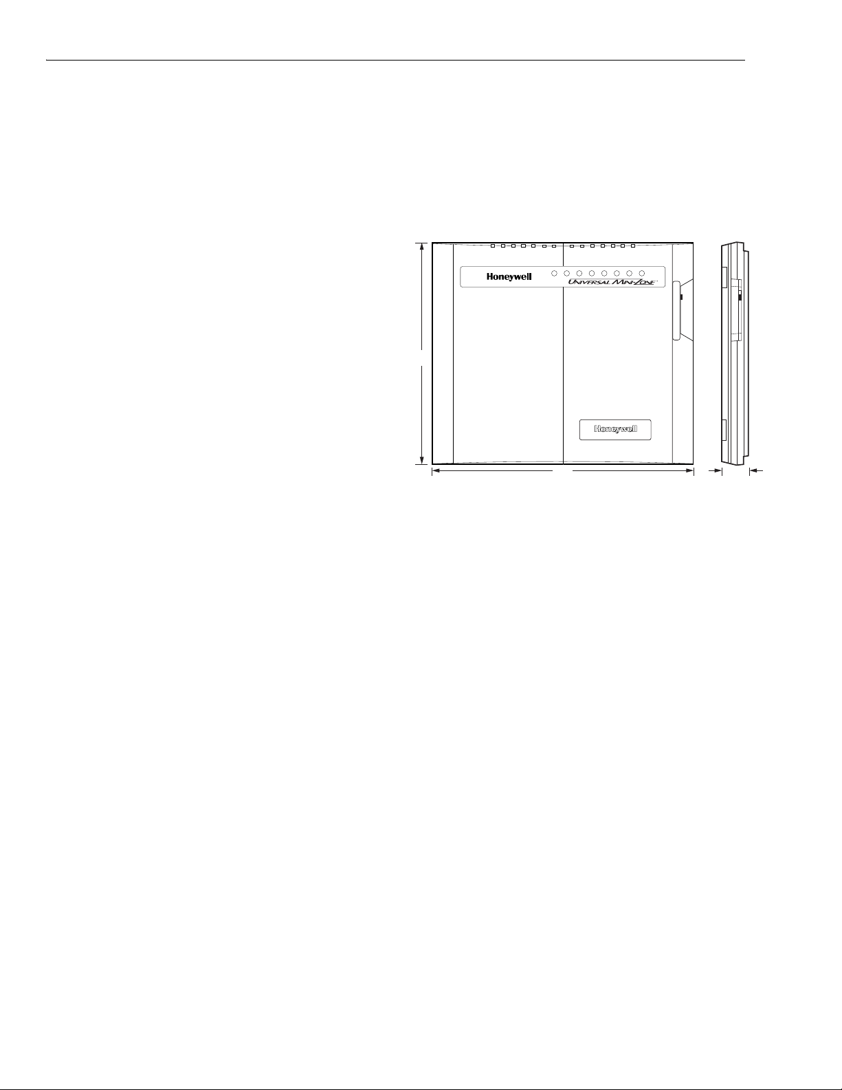
Dimensions: See Fig. 1.
Mounting: Mounts with four one-inch no. 8 screws (provided)
through holes in cabinet. Wall anchors provided.
Wiring: 18 to 22 gauge wire for all equipment and system
connections.
Wiring Connections:
Thermostat: R-C-E-W1-Y1-G-W2-Y2-O-B-L.
Dampers: M6 (Closed); M4 (Open); M1 (Common).
Discharge Air Temperature Sensor: DATS-DATS.
Transformer: R-C.
Equipment: RC-RH-W1-W2-E-B-O-Y1-Y2-G.
0-3/4
(273)
12-3/4
(273)
1-7/8
(47)
Fig. 1. EMM-3U dimensions in in. (mm).
Approvals:
Federal Communications Commission: Class B.
NEMA DC-3: Not required.
Thermostats (See Table 1):
Most conventional four-wire (R, W, Y, G) thermostats can be
used to control conventional, heat pump, or multi-stage
equipment.
Manual or automatic changeover switching thermostats can
be used.
Multi-stage or select heat pump thermostats can also be used.
M20779A
ORDERING INFORMATION
When purchasing replacement and modernization products from your TRADELINE® wholesaler or distributor, refer to the
TRADELINE® Catalog or price sheets for complete ordering number.
If you have additional questions, need further information, or would like to comment on our products or services, please write or
phone (1-800-468-1502):
1. Your local Automation and Control Solutions Sales Office (check white pages of your phone directory).
2. Honeywell Automation and Control Solutions Customer Care
1985 Douglas Drive North
Golden Valley, MN 55422
In Canada—Honeywell Limited/Honeywell Limitée, 35 Dynamic Drive, Scarborough, Ontario M1V 4Z9.
International Sales and Service Offices in all principal cities of the world. Manufacturing in Australia, Canada, Finland, France,
Germany, Japan, Mexico, Netherlands, Spain, Taiwan, United Kingdom, U.S.A.
68-0237-2 2
Page 3
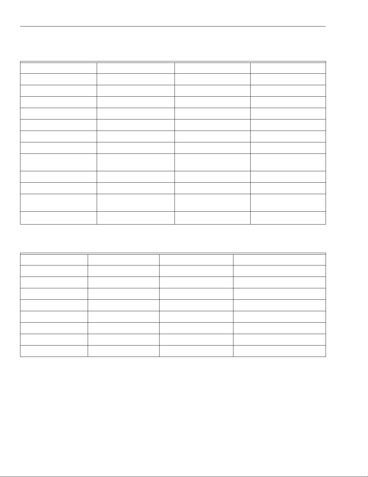
Table 1. Recommended Thermostats.
System Non-Programmable Programmable
SingleStag e
T87F1859/Q539A1014
T87F4010/Q539A4026
T8501D1046
T8400C1016
T8400C1040
T8400C1099
T8501D1111
T8601D2027
T8600D2069
T8600D2028
T8601D2019
T8602D2018
T8602D2000
T8000C1002
T8000C1010
T8001C1019
PC8900/W8900A,C
Heat
Pump
MultiStag e
b
b
Y594R1243
Y594G1252
T8411R1002
T8411R1028
T8424D1008
T8424D1016
T8524D1007
T8524D1015
Y594D1347
a,c,d
a,e
f
T8611G2051
T8011R1006
T8011R1014
T8011F1002
T8624D2004
T8624D2012
T8024D1002
T8024D1010
T8024F1007
a
T8524D1015
a
Heat pump thermostat with single Y first-stage terminals. See
Heat Pump Thermostats section and Fig. 6.
b
Multi-stage and heat pump thermostats are not required to
control multi-stage and heat pump systems. They are used
only when second stage or emergency heat control from the
zone thermostat is needed.
c
The Y594R1243 must be wired to the panel using the B ter-
minal for changeover.
d
Cut thermostat second-stage variable heating anticipator
wire (gray).
e
Cut thermostat first-stage fixed heating anticipator wire (bare)
and second-stage variable heating anticipator wire (gray).
f
Cut thermostat second-stage cooling anticipator wire (lowest
bare wire).
EMM-3U UNIVERSAL ELECTRONIC MINIZONE™ PANEL
Recommended Dampers (See Table 2):
Five ZD or ARD dampers maximum connected to each panel
and a maximum of five dampers per zone.
Use SDCR for additional dampers required on one zone.
Dampers are connected to M1 Common, M4 Open, and M6
Closed (see Fig. 8-12 for hookups).
Table 2. Recommended Dampers.
Honeywell Damper Type Round Rectangular
Power-open/power closed
(for systems >2000 cfm)
MARD D642 using
ML6161 Motor
Actuator
Spring-open/power-closed
ARD ZD
(for systems </= 2000 cfm)
Damper Connections:
Motor Terminal Damper Action
Common/M1 Common
Open/M4 Power Open
Closed/M6 Power Close
Accessories: For required accessories, see Table 3.
Table 3. Required Accessories.
Accessory Description
40 VA transformer AT140D1046
Capacity protector C7735A1000
Round static pressure
regulator damper
Rectangular static
pressure regulator
damper
7 SPRD
8 SPRD
9 SPRD
10 SPRD
12 SPRD
14 SPRD
16 SPRD
12 x 8 SPRD
12 x 10 SPRD
12 x 12 SPRD
20 x 8 SPRD
20 x 10 SPRD
20 x 12 SPRD
300 cfm
400 cfm
600 cfm
750 cfm
1200 cfm
1800 cfm
2400 cfm
1000 cfm
1200 cfm
1400 cfm
1600 cfm
2000 cfm
3000 cfm
3 68-0237-2
Page 4
EMM-3U UNIVERSAL ELECTRONIC MINIZONE™ PANEL
U
O
L
INSTALLATION
Mounting
CAUTION
Equipment Damage Hazard.
Do not mount EMM-3U inside HVAC equipment.
Mount only on wall or on cold air return.
1. Mount the thermostats in each zone of the living space
using the installation instructions provided with each
thermostat.
2. Mount the dampers in the ductwork using the installation instructions provided with each damper.
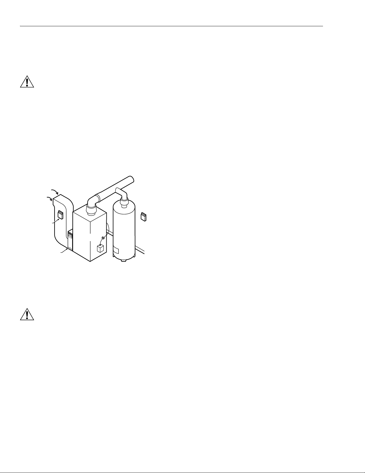
3. Mount the EMM-3U zone panel near the HVAC equipment; locate it on a wall or on the cold-air return. See
Fig. 2.
4. Level the EMM-3U for appearance only.
RETURN
AIR
EMM-U3
PTIONAL
OCATION
ELECTRONIC AIR CLEANER
FURNACE
OR BOILER
HIGH
EFFICIENCY
AIR CLEANER
Fig. 2. EMM-3U mounting location.
WATER
HEATER
EMM-3
M14762
Thermostat Wiring
Conventional Equipment
Conventional (RWYG) thermostats can be used to control
conventional, multi-stage and heat pump equipment. When
single-stage thermostats are used, stages are engaged
through the on-board 5 - 60 minute timer. If the equipment is a
heat pump, the EMM-3U panel controls the reversing valve. If
the thermostat has a common terminal, it is wired to C on the
panel, see Fig. 3. Multi-stage conventional (non-heat pump)
thermostats are wired with the second stage of heat and cool
on the thermostat to W2 and Y2 on the panel. Leave the O/B
thermostat jumper on the EMM-3U disconnected.
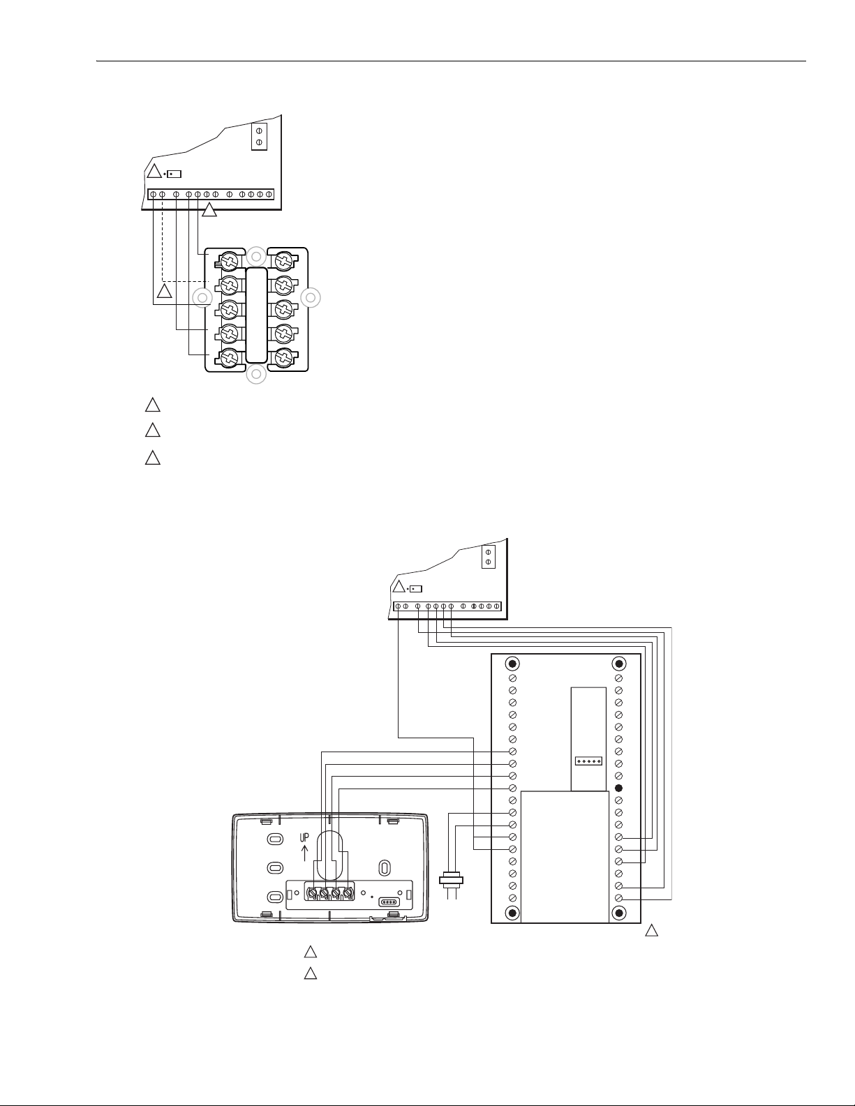
The PC8900 can be used as a zone thermostat. See Fig. 4 for
hookup. The PC8900 with the W8900A or C controls up to 2
heat and 2 cool stages of conventional equipment. The
PC8900 with the W8900A also controls heat pump
equipment.
Connect a jumper on the W8900 from Rc to Rh as shown.
Wire terminals R and C to a transformer. Alternately, if the
zone control system current draw is within specifications, the
R and C on the W8900 could be connected to R and C on the
EMM-3U. The PC8900/W8900 draws 5 VA.
Heat Pump Equipment
Select a heat pump thermostat from Table 1. If the thermostat
selected has a separate Y1 and W1 wire, connect as shown in
Fig. 5, leaving the zone O/B thermostat type jumper on the
EMM-3U disconnected
If the PC8900/W8900A is used, wire as shown in Fig. 4. This
hookup engages second stage heat based on thermostat
demand, but the Em Heat switch on the panel must be used to
switch the panel to emergency heat.
WIRING
NOTE: The thermostat Em Heat switch does not switch the
panel to emergency heat.
If the thermostat selected from Table 1 has a single Y terminal
CAUTION
Voltage Hazard.
Can cause electrical shock or equipment damage.
Disconnect power before continuing installation.
Wiring must comply with applicable codes, ordinances and
regulations.
1. Connect thermostats as shown in Fig. 3-7.
2. Connect dampers as shown in Fig. 8-12.
3. Connect C7735A1000 Discharge Air Temperature Sen-
sor (DATS) to the DATS terminals. The wires are not
polarized; see Fig. 13.
4. Connect the HVAC equipment to the EQUIP terminals
on the panel; see Fig. 13-18.
for first stage heat and cool, wire as shown in Fig. 6 and 7.
Wire either O or B (not both) from the thermostat to the O/B
terminal on the EMM-3U. Locate the O/B thermostat jumper
on the EMM-3U near each zone thermostat wiring terminal.
Connect the jumper if O is used or leave the jumper
disconnected if B is used. Connect second stage, auxiliary
heat, to W2.
Conventional single stage thermostats can be used to control
a heat pump if wired as shown in Fig. 3. In this case, the panel
operates the reversing valve, the second stage is brought on
by the panel stage timer, and emergency heat is activated by
the EM heat switch on the panel. Leave the O/B thermostat
type jumper disconnected when using conventional
thermostats.
5. Connect a 40 VA, 24 Vac transformer to R (hot) and C
(common). This must be a dedicated transformer. See
Fig. 13.
68-0237-2 4
Page 5
EMM-3U UNIVERSAL ELECTRONIC MINIZONE™ PANEL
A
H
R
C
24VAC
3
G W2Y2 O/B M6M4M1Y1W1/ECR L
40VA
2
EMM-3U THERMOSTAT
CONNECTORS
G
C
1
R
W
Y
TYPICAL SINGLE STAGE
THERMOSTAT WIRING
COMMON (C) TERMINAL IS USED ONLY BY THERMOSTATS
1
THAT REQUIRE A COMMON WIRE.
2
MULI-STAGE THERMOSTATS ARE WIRED SIMILARLY BUT WIT
Y2 AND W2 USED FOR SECOND STAGE COOL AND HEAT.
LEAVE O/B JUMPER ON EMM-3U DISCONNECTED.
3
M20780
Fig. 3. Typical conventional thermostat wiring.
2
O/BW1/E
GW2Y2 M6M4M1Y1CRL
R
C
24VAC
40VA
EMM-3U THERMOSTAT
CONNECTORS
CO
2
1
2
3
4
GND
C
R
RH
RC
HUM
24 VAC
HUM
VNT
120 VAC
1234
VNT
PC8900
W8900A/C IS RECOMMEDED FOR CONVENTIONAL AND HEAT PUMP APPLICATIONS. THE W8900B CANNOT
1
SWITCH THE PANEL TO EMERGENCY HEAT.
2
LEAVE O/B JUMPER ON EMM-3U DISCONNECTED.
S1
S
T1
T
OUT
OUT
LED
G
Y2
Y1
W1
W2
W8900A,C
1
M20781A
Fig. 4. PC89800 with W8900A,C Thermostat wiring.
5 68-0237-2
Page 6
EMM-3U UNIVERSAL ELECTRONIC MINIZONE™ PANEL
A
H
A
T.
A
T.
R
C
24VAC
3
GW2Y2 M6M4M1Y1CRL
40VA
O/BW1/E
EMM-3U THERMOSTAT
CONNECTORS
R
C
24VAC
3
GW2Y2 M6M4M1Y1CRL
40VA
O/BW1/E
EMM-3U
THERMOSTAT
CONNECTORS
G
1
C
R
W1
Y1
COMMON (C) TERMINAL IS USED ONLY BY THERMOSTATS
1
THAT REQUIRE A COMMON WIRE.
2
JUMP E TERMINAL TO W1 FOR EMERGENCY HEAT.
3
LEAVE O/B JUMPER ON EMM-3U DISCONNETED.
L
W2
2
E
B
O
HEAT PUMP THERMOSTAT WIT
SEPARATE W1 AND Y1
THERMOSTAT WIRING
M20782
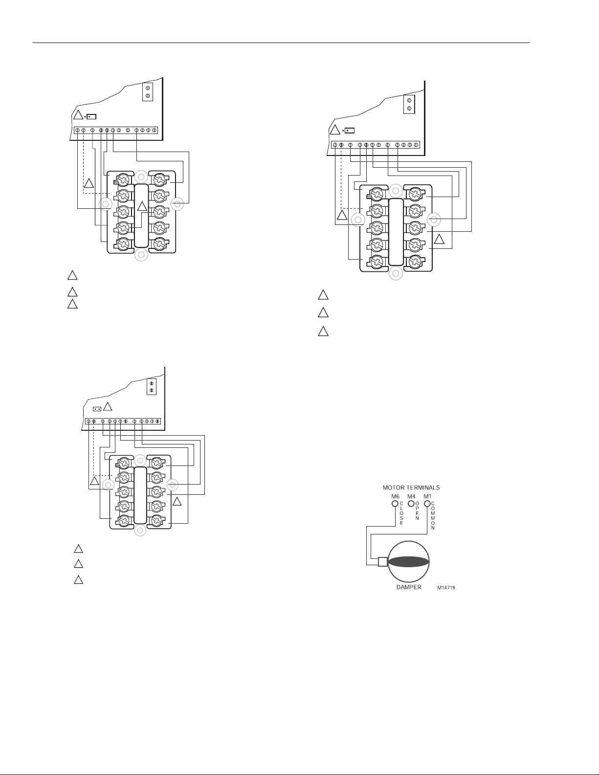
Fig. 5. Heat pump thermostat with separate W1 and Y1
terminal wiring.
R
C
24VAC
3
GW2Y2 M6M4M1Y1CRL
G
C
1
R
Y1
COMMON (C) TERMINAL IS USED ONLY BY THERMOSTATS
1
THAT REQUIRE A COMMON WIRE.
2
NORMALLY, CONNECT E ON THERMOSTAT TO W1/E ON PANEL.
ALTERNATELY, INSTALL JUMPER FROM E TO Y1 ON THERMOSTA
3
CONNECT O/B TERMOSTAT JUMPER ON EMM-3U PANEL IF
USING O FROM THERMOSTAT; DISCONNECT IF USING B.
40VA
O/BW1/E
EMM-3U
THERMOSTAT
CONNECTORS
L
W2
E
B
O
HEAT PUMP THERMOSTAT WITH
SINGLE Y THERMOSTAT WIRING
2
M20783
G
C
1
R
W1
Y1
COMMON (C) TERMINAL IS USED ONLY BY THERMOSTATS
1
THAT REQUIRE A COMMON WIRE.
2
NORMALLY, CONNECT E ON THERMOSTAT TO W1/E ON PANEL.
ALTERNATELY, INSTALL JUMPER FROM E TO Y1 ON THERMOSTA
3
CONNECT O/B TERMOSTAT JUMPER ON EMM-3U PANEL IF
USING O FROM THERMOSTAT; DISCONNECT IF USING B.
L
W2
E
2
B
O
HEAT PUMP THERMOSTAT WITH
SINGLE Y THERMOSTAT WIRING
M20784
Fig. 7. Heat pump thermostat with single Y1 using B for
changeover thermostat wiring.
Damper Wiring
ARD or ZD Dampers
Wire the ARD or ZD damper to the panel as shown in Fig. 8.
Multiple dampers can be wired in parallel. Use these dampers
on systems up to 2000 cfm.
Fig. 6. Heat pump thermostat with single Y1 using O for
changeover thermostat wiring.
68-0237-2 6
Fig. 8. Wiring ARD or ZD Damper to panel.
AOBD Dampers
Wire the AOBD dampers to the panel as shown in Fig. 9. Two
AOBD can be wired in tandem as shown in Fig. 10. More than
two AOBD dampers require the Slave Damper Control Relay
(SDCR).
Page 7

EMM-3U UNIVERSAL ELECTRONIC MINIZONE™ PANEL
F
7
8
S
S
6
A
MOTOR TERMINALS
M6 M4 M1
4
5 6
123ZX
IELD JUMPER
DAMPER MOTOR
M1906
Fig. 9. Wiring AOBD Damper to panel.
MOTOR TERMINAL
FIELD JUMPER
4 5 6
123ZX
DAMPER MOTORS
M6 M4 M1
4
5 6
123
Z
X
M1906
Fig. 10. Wiring two AOBD dampers in parallel.
ZONE CONTROL PANEL
DAMPER TERMINALS
M6 M4 M1
R8222 RELAY
R
C
ML6161
COM
CCW
CW
M20548
Fig. 12. MARD or ML6161 Damper Motor Actuator using
R8222 Relay wiring.
Discharge Air Sensor Wiring
Wire the C7735 Discharge Air Temperature Sensor (DATS) to
the panel as shown in Fig. 13 -16.
The Purge LED (amber) flashes in all modes except purge if:
1. No DATS is connected to the EMM-3U.
2. There is a problem with the DATS sensor.
3. There is a problem with the DATS wiring.
The zone control panel will continue to operate correctly when
the purge LED is flashing but without the high and low limit
protection.
MARD Dampers or Dampers Using ML6161 Motor
Actuator
Wire the MARD Damper or ML6161 Actuator to the panel as
shown in Fig. 11. These are floating control actuators, but are
controlled as two-position devices on the EMM-3U Panel.
Multiple dampers can be wired in tandem.
The ML6161 Motor causes the damper LED to illuminate
green constantly. Wire a relay as shown in Fig. 12 to restore
damper position indication.
Use the MARD or D642 Damper with the ML6161 on systems
2000 cfm and higher.
ZONE PANEL
CONNECTION
M1 M4
MARD
CW
COM
CCW
Fig. 11. Wiring MARD Damper or ML6161 Actuator to
panel.
M
M20136A
Equipment Wiring
Conventional Equipment
Wire the heating and cooling equipment to the equipment
terminals on the EMM-3U Panel as shown in Fig. 17.
Conventional Equipment: Leave DIP switch 4 set to On.
Electric Furnace: Set DIP switch 7 to Off to energize the fan
with a call for heat.
Oil Heat: Wire the oil primary T, T terminals to the Rh and W
equipment terminals. (If the oil primary has powered
terminals, remove the Rh and Rc jumper.) See Fig 15 and 16.
Multi-Stage: Wire the equipment as shown in Fig. 13 using the
W2 for second stage heating, and the Y2 for second stage
cooling.
See the Operation section for stage configuration and other
settings.
7 68-0237-2
Page 8

EMM-3U UNIVERSAL ELECTRONIC MINIZONE™ PANEL
Hot Water Heat Systems
Hydronic Heat
Hydronic heat systems using zone valves or circulator relays
for heating and dampers for cooling can be controlled by the
panel. In this hookup, one thermostat is used per zone to
control both heating and cooling. Use thermostats with
separate Rc and Rh terminals to isolate the heating and
cooling circuits. Connect the thermostat Rh and W to the zone
valve and the Rc, Y and G to the zone control panel. Wire the
thermostats and air conditioning equipment the same as for
conventional equipment; see Fig. 3 and 16.
Hydro Heat
Hydro heat systems using a boiler and hot water coil can be
used with this zone control panel. Wire the zone valve or
circulator relay to equipment terminals Rh and W. The Rc and
Rh jumpers located above the equipment terminals must be
removed if a separate transformer powers the heating and
cooling circuits. Wire the cooling equipment, thermostats, and
dampers the same as for conventional equipment; see Figure
19. Set DIP switch 7 to off if it is necessary for the fan to be
energized on a call for heat. Alternatively, an Aquastat can be
used to engage the blower based on water temperature.
Heat Pump Equipment
See Fig. 17 and 18 for heat pump equipment wiring. Refer to
the manufacturer instructions for additional wiring details and
substitute the EMM-3U equipment terminals for the
thermostat terminals shown.
If the same heat source is used for auxiliary heat and
emergency heat:
• Connect the auxiliary heat to W2.
• Wire a jumper from W2 to E.
• Set DIP switch 12 to Off.
If auxiliary heat is separate from emergency heat:
• Connect the auxiliary heat to W2.
• Connect the emergency heat to E.
• Leave DIP switch 12 set to On.
Connect the changeover relay to the O or B equipment
terminal (O is energized when the panel is in the cool mode, B
is energized when the panel is in the heat mode).
IMPORTANT
Connect the compressor wire to the Y1 terminal. If there is a
2
To control a two-stage heat pump with auxiliary heat, select
the TZ-4 TotalZone Zone Control panel.
Set DIP switch 4 to Off for heat pump operation, and set DIP
switch 7 to Off for fan on a call for heat.
See the Operation section for additional configuration
settings.
Some heat pump manufacturers (such as York and
Trane) use the B terminal as the transformer common. Do not connect the common from the equipment to the zone control panel.
nd
stage compressor, wire it to Y2 with a jumper to W2.
Transformer
Wire a dedicated transformer to the R (hot) and C (common)
terminals on the zone control panel as shown in Fig.13. One
40 VA, 24 Vac transformer powers up to five ARD or ZD
Dampers and the panel.
68-0237-2 8
Page 9

M14763A
Single Transformer
S
T
t
a
F
t
H
I
L
(
L
M14766A
M14764A
Heating/Cooling
systems require a
jumper to be installed
connecting R
(factory installed).
24 Volt Equipment
Transformer(s)
Cooling Transformer
Heating Transformer
First Stage Heat Relay
econd Stage Heat Relay
First Stage Cool Relay
Second Stage Cool Relay
his diagram shows the typical
wo-stage equipment, thermostat,
nd damper motor connections.
or specific wiring for other
hermostats, damper motors, and
VAC Equipment, refer to the
nstallation Instructions.
and R
H
Fan Relay
C
EMM-3U UNIVERSAL ELECTRONIC MINIZONE™ PANEL
HEAT COOL PURGE FAN EM. HEAT ZONE 1 ZONE 2 ZONE 3
LED STATES:
RED HEAT LED HEATING MODE
GREEN COOL LED COOLING MODE
R
C/RH
JUMPER
EQUIPMENT
CRR
1
CW2Y2
Zone 1 Thermostat
YELLOW PURGE LED PURGE MODE
GREEN FAN LED FAN MODE
RED EM HEAT LED EM HEAT MODE
FLASHING RED HEAT LED ZMS SENSOR EXCEEDS HIGH LIMIT IN HEATING
FLASHING GREEN COOL LED ZMS SENSOR EXCEEDS LOW LIMIT IN COOLING
FLASHING YELLOW PURGE LED
ZONE LEDS
R
C
ON (GREEN COLOR) DAMPER IS OPEN OR OPENING
R
OFF (NO COLOR) DAMPER IS CLOSED OR CLOSING
H
W
1
MOMENTARY PUSHBUTTON SWITCHES:
W
2
BOOT USED TO CLEAR THE SYSTEM AND MICROPROCESSOR.
E
PURGE OVERRIDE USED TO BYPASS THE PURGE CYCLE WHILE TROUBLESHOOTING.
B
DIP SWITCH SETTINGS
O
1 STAGE TIMER
Y
2 STAGE TIMER ON OFF
1
3 STAGE TIMER 1 0 TABLE
Y
2
4 SYSTEM TYPE CONV HEAT PUMP
G
5 ZMS HIGH LIMIT 160 F 120 F
6 ZMS LOW LIMIT 40 F 48 F
7 HEAT FAN HVAC PANEL
8 PURGE FAN HVAC PANEL
9 PURGE DAMPER NO CHG OPEN
10 PURGE TIME 2.0 MIN 3.5 MIN
11 EM HEAT FAN HVAC PANEL
12 2ND STAGE EM HEAT YES NO
SEE
TABLE
ZONE 1
O/BW1/E O/BW1/E O/BW1/E
GW2Y2 M6M4M1
GY1Y1W1
Power-open
Power-closed
(Opposed Blade
Damper Motors)
L
456Z
123X
NO ZMS SENSOR INSTALLED OR ZMS SENSOR FAILUR
#1 #2 #3 TIME
1 1 1 5 MIN
1 1 0 10 MIN
1 0 1 15 MIN
1 0 0 20 MIN
0 1 1 30 MIN
0 1 0 45 MIN
0 0 1 60 MIN
0 0 0 NO TIMER
ZONE 2
CRR
GW2Y2 M6M4M1
1 12 2 2
GY1Y1W1
CW2Y2
Zone 2 Thermostat
Power-closed
Spring-open
(Model ZD)
L
BOOT PURGE
O
N
1
2 3 4 5 6 7 8 9 101112
222
CRR
CW2Y2
Zone 3 Thermostat
OVERRIDE
E
DATS
DATS
ZONE PANEL
TRANSFORMER
EM
HEAT
R
C
24V AC
ZONE 3
GW2Y2 M6M4M1
GY1Y1W1
Power-closed
Spring-open
(Model ARD)
L
ON
OFF
(See C7735
Installation
Instructions
for further
information.)
40VA
24 Volt 40VA
Transformer
ZONE
THERMOSTATS
1 C terminal
connection is not
required on battery
powered, power
stealing, or some
electromechanical
thermostats.
2 Leave jumper
disconnected for
conventional
thermostats.
ZONE DAMPER MOTORS
M1 - common
M4 - power open
M6 - power closed
Discharge Air
Temperature
Sensor
CR
Fig. 13. EMM-3U System wiring diagram.
1
TRANSFORMER
HOT)
2
Fig. 14. Conventional single-stage single transformer
LEAVE FACTORY INSTALLED RH TO RC JUMPER IN PLACE
1
FOR SINGLE TRANSFORMER SYSTEM.
COOLING
CONTACTOR
HEAT
RELAY
FAN
RELAY
system wiring diagram.
PANEL
1
R
C
R
H
W
1
W
2
E
B
O
Y
1
Y
2
G
L1
OIL PRIMARY
(HOT)
T T
L2
COOLING
L1
(HOT)
L2
1
24V
REMOVE FACTORY INSTALLED RH TO RC JUMPER.
CONTACTOR
FAN
RELAY
PANEL
1
R
C
R
H
W
1
W
2
E
B
O
Y
1
Y
2
G
Fig. 15. EMM-3U oil heating wiring diagram.
9 68-0237-2
Page 10

EMM-3U UNIVERSAL ELECTRONIC MINIZONE™ PANEL
L
(
L
L
(
A
L
(
L
A
.
L
(
L
A
.
PANEL
HEATING
1
TRANSFORMER
HOT)
L2
COOLING
1
TRANSFORMER
HOT)
2
REMOVE FACTORY INSTALLED RH TO RC JUMPER.
1
HEAT
RELAY
COOLING
CONTACTOR
FAN
RELAY
1
R
C
R
H
W
1
W
2
E
B
O
Y
1
Y
2
G
M14765
Fig. 16. Two-transformer system wiring diagram.
PANEL
1
TRANSFORMER
HOT)
2
SECOND STAGE
HEAT RELAY
EM HEAT
RELAY
COOLING
CHANGE OVER
VALVE
FIRST STAGE
COMPRESSOR
RELAY
1
R
C
R
H
W
1
W
2
E
B
O
Y
1
Y
2
G
PANEL
1
TRANSFORMER
HOT)
2
LEAVE FACTORY INSTALLED RH TO RC JUMPER IN PLACE
1
SECOND STAGE
HEAT RELAY
COOLING
CHANGE OVER
VALVE
FIRST STAGE
COMPRESSOR
RELAY
FAN
RELAY
R
C
R
H
W
1
W
2
E
B
O
Y
1
Y
2
G
M14767
1
Fig. 18. Single-stage heat pump with auxiliary heat wiring
diagram.
FAN
RELAY
LEAVE FACTORY INSTALLED RH TO RC JUMPER IN PLACE
1
M14767
Fig. 17. Single-stage heat pump with separate auxiliary
and emergency heat wiring diagram.
68-0237-2 10
Page 11

EMM-3U UNIVERSAL ELECTRONIC MINIZONE™ PANEL
M20888
T
a
h
u
s
F
t
HEAT COOL PURGE FAN EM. HEAT ZONE 1 ZONE 2 ZONE 3
24 Volt Equipment
R on Fan Center for AC
Compressor Relay
Fan Relay
his diagram shows the typical
ir conditioning system and
ydronic zone valve hookup
sing common dampers and
ingle stage thermostats.
or specific instructions, refer
o Installation Instructions.
R
C/RH
JUMPER
EQUIPMENT
R
C
R
H
W
1
MOMENTARY PUSHBUTTON SWITCHES:
W
2
BOOT USED TO CLEAR THE SYSTEM AND MICROPROCESSOR.
E
PURGE OVERRIDE USED TO BYPASS THE PURGE CYCLE WHILE TROUBLESHOOTING.
B
DIP Switches (see Installation Instructions for details):
O
1, 2, 3: Set to off for 1 stage heat and cool
Y
1
4: Set to on for conventional equipment
Y
5: Set to on for 160°F high limit
2
6: Set to on for 40°F or off for 48°F
G
7: Set to on
8: Set to on for no purge fan after call for heat or cool
9: Set to on
10: Set to on
11: Set to on
12: Set to on
ZONE 1
CRcR
Rh RcRh Rc Rh
Zone 1 Thermostat
Yellow Leads
V8043E
Power-open
Power-closed
(Opposed Blade
Damper Motors)
O/BW1/E O/BW1/E O/BW1/E
GW2Y2 M6M4M1
GY1YW
L
456Z
123X
ZONE 2
GW2Y2 M6M4M1
CRL
GY1YW
Zone 2 Thermostat
Th/Tr
Th
V8043F V8043F
Power-closed
Spring-open
(Model ZD)
DATS
DATS
EM
HEAT
R
C
24 VAC
ON
OFF
40VA
BOOT PURGE
OVERRIDE
O
N
1
2 3 4 5 6 7 8 9 101112
ZONE PANEL
TRANSFORMER
111
Th
ZONE 3
GW2Y2 M6M4M1
CRL
GY1YW
Zone 3 Thermostat
Th/Tr
Power-closed
Spring-open
(Model ARD)
Discharge Air
Temperature
Sensor
(See C7735
Installation
Instructions
for further
information.)
CR
24 Volt 40 VAC
Transformer
1 Leave this jumper
disconnected.
ZONE DAMPER MOTORS
M1 - common
M4 - power open
M6 - power closed
Fig. 19. EMM-3U with Air Conditioning Zoned with Dampers and Hydronic Heat Using V8043 Zone Valves.
STARTUP AND CHECKOUT
5. Verify that the heat LED is red and the zone one damper
remains green while the other damper LEDs turn off.
6. Raise zone two setpoint to call for heat. Lower zone one
After the installation is complete, verify correct operation:
1. Place the Em Ht switch in the Off (down) position.
2. Verify that DIP switches are set correctly.
3. Turn on power to the EMM-3U Panel and set the ther-
mostats so no zones are calling.
a. EMM-3U enters the Purge Mode, opening all damp-
ers and operating the fan for two or three and onehalf minutes (configurable). In Purge, damper LEDs
setpoint to stop the call for heat to that zone.
7. Verify that zone one LED turns off and zone two LED
turns green.
8. Repeat for zones two and three.
9. Alternately, set the System switch to Cool, and lower the
setpoint to call for cooling.
10. Verify that the green cool LED illuminates.
are green to indicate the dampers are open.
NOTE: If a Discharge Air Temperature Sensor is not con-
nected to the panel, the purge LED flashes in all
modes other than Purge.
b. Press the Purge Override button on the panel to exit
the Purge mode early.
4. Set the zone one thermostat to heat and raise the set-
OPERATION
Identifying DIP Switches
This panel has one bank of 12 DIP switches numbered
starting with 1 on the left. The switches are shipped in the On
(Up) position. See Fig. 13 and Tables 4 and 5.
point to call for heat.
11 68-0237-2
Page 12

EMM-3U UNIVERSAL ELECTRONIC MINIZONE™ PANEL
Sequence of Operation
• When there is no call for heat, cool, or fan, the EMM-3U is
in the Idle mode. No system LEDs are illuminated and the
damper LEDs are green to indicate open.
• On a call for heat, cool, or fan, the calling zone damper
stays open, and the other zone dampers close:
— Panel energizes the HVAC equipment and conditioned
air is delivered to the calling zone.
— Heat LED (red), cool LED (green), or fan LED (green)
illuminates to indicate equipment operation.
— Fan LED illuminates only during a call for circulation; it
does not illuminate during a call for heat or cool.
• When the call is satisfied, the system enters the Purge
mode. After Purge, all dampers return to the Open position
• Any zone thermostat can call for heating or cooling. If there
are co-existing calls for heat and cool, the panel accepts
the first call.
• Once a call is satisfied, or a maximum of 20 minutes has
elapsed, the panel switches to allow the opposite call after
completing Purge mode.
Purge Mode
• At the end of every call for heat or cool, the panel enters a
Purge mode that holds open the calling zone damper for
two minutes (default) or three and one-half minutes.During
this time, the panel or the HVAC equipment can be
configured to operate the fan.
• The Purge LED lights to signal that the system is in the
Purge mode. Pressing the purge override button overrides
the Purge mode.
• Unless there is a new call for heat or cool during the Purge
mode, all dampers are moved to the Open position at the
end of Purge.
• The panel can be configured to open all dampers during
purge mode.See Table 4 to configure the Purge mode
using DIP switches 8, 9 and 10.
Individual Zone Fan Control
• The fan switch of each thermostat controls the fan
operation for that zone.
• When the Fan switch is in the On position, the fan is
energized, and dampers close to zones where the Fan
switch is in Auto position.
• During a call for heat or cool at this time, the circulation
mode ceases, and the heat or cool call is honored.
• When the zone calling is satisfied, the circulation call
resumes.
Single- and Multi-Stage Operation
The panel can control up to two stages of heat and cool:
• First stage is energized by the thermostat
• Second stage of heating or cooling can be energized by
the thermostat or timer.
Single-Stage
Select a single stage thermostat, see Table 1. Set DIP
switches 1, 2, and 3 to Off to disable the stage timer.
Multi-Stage
THERMOSTAT-CONTROLLED STAGES
• Select a multi-stage thermostat, see Table 1, that
energizes W2 and Y2 for second stage of heat and cool.
• Configure DIP switches 1, 2 and 3 to Off to disable the
stage timer.
Timer Controlled Stages
• The panel stage timer energizes the second stage of heat
or cool after the first stage has been calling for a specified
amount of time.
• Second stage remains energized until the call for heat or
cool is satisfied.
• See Table 5 for stage timer configuration.
Heat Pump Operation
The panel can control single or two stage heat pumps with or
without auxiliary heat:
• Set DIP switch 4 to Off for heat pump control. This
energizes the Y1 on a call for first stage heat or cool.
• Set DIP switch 7 to Off to engage the fan with a call for
heat.
Thermostat Controlled Stages
• Select a thermostat from Table 1. Configure DIP switches
1,2, and 3 to off to disable the stage timer.
— When thermostat calls for first stage, panel energizes
Y1, G and the correct reversing valve terminal.
— When the thermostat calls for second stage heat on
W2, the panel energizes the equipment W2 terminal.
• Recommended heat pump thermostats can switch the
panel to emergency heat:
— In this mode, Y1 equipment terminal is disabled and E
is energized on a call for heat.
— If the same source of heat is used for emergency heat
and auxiliary heat, W2 and E equipment terminals
must be jumpered.
• Emergency heat can be energized by the Em Heat switch
on the panel.
• If the equipment is a two-stage heat pump, W2 and Y2
equipment terminals must be jumpered and wired to the
second stage compressor contactor.
• If the equipment is a two-stage heat pump with auxiliary
heat, select the TZ-4 TotalZone™ panel.
Timer Controlled Stages
If single-stage thermostats are used, the EMM-3U can
energize second stage using stage time:
• The timer can be set to engage second stage heat or cool
after the first stage has been calling for the specified length
of time.
• See Table 5 for DIP switch configuration.
Thermostat Operation
Conventional Thermostats
Conventional (R,W,Y,G) heat/cool thermostats can be used
with the EMM-3U to control single or multi-stage gas, electric,
or oil systems and heat pumps with or without auxiliary heat.
• For two stage heat or cool equipment, configure the stage
timer with DIP switches 1, 2 and 3. See Table 5. This
enables the panel to engage second stage after stage one
has been calling for the specified length of time.
68-0237-2 12
Page 13

EMM-3U UNIVERSAL ELECTRONIC MINIZONE™ PANEL
• Heat pumps can be controlled by conventional thermostats
because the EMM-3U controls the reversing valve based
on whether the panel is in heat or cool.
— It controls auxiliary heat through the stage timer.
— For heat pump applications, set DIP switch 4 to Off.
• In all cases, when a conventional thermostat is used, the
O/B thermostat type jumper located next to each
thermostat connection must remain disconnected.
Heat Pump Thermostats
Heat pump thermostats that have a single Y terminal for first
stage heat and cool and those with separate Y1 and W1 can
be used with the EMM-3U. Thermostats of either type can be
used on any zone. Set DIP switch 4 to Off for heat pump
control.
HEAT PUMP THERMOSTATS WITH SINGLE Y OUTPUT
Thermostats with a single Y wire for first stage heat and cool
can be connected to the EMM-3U. O/B thermostat type
jumpers must be set correctly:
— If the thermostat uses O for changeover, connect it to
the O/B thermostat terminal on the panel and connect
the O/B jumper on the panel. (There is one jumper for
each zone.)
— If B is used, leave the jumper disconnected.
HEAT PUMP THERMOSTATS WITH SEPARATE Y1 AND W1
TERMINALS
• Heat pump thermostats with separate Y1 and W2 terminals
for first stage can be used to control a heat pump.
• On these installations, it is not necessary to connect O or B
from the thermostat.
• Leave the O/B thermostat type jumper disconnected.
Manual and Automatic Changeover
Thermostats
Manual or automatic changeover thermostats can be used.
• The panel determines the call for heat or cool based on
which was called for first.
• Subsequent calls for heat or cool are honored when the
initial call is satisfied, or 20 minutes has elapsed.
Rebooting the Microprocessor
To reset the panel, press and release the Boot button. The
system reboots and enters the Purge mode.
Discharge Air Temperature Sensor
The C7735A1000 Discharge Air Temperature Sensor is a
supply-duct-mounted temperature probe used to control
capacity and prevent high limit or coil icing.
• The sensor attaches to the two DATS terminals on the
panel.
• When a high or low limit is reached, the panel shuts off the
equipment and keeps the fan operating for 2-1/2 minutes.
• After this time, it re-energizes the equipment after the
discharge air temperature recovers by ten degrees.
• When the DATS exceeds the high or low limit, the Heat
(red) or Cool (green) LED flashes.
• Set the temperature to 120°F for heat pump systems or
160°F for fossil fuel. The low limit can be set to 40°F or
48°F.
See Table 4 to configure high and low limit using DIP switches
5 and 6.
Emergency Heat Control
NOTE: Emergency heat is defined as using an auxiliary heat
source without using the heat pump. When the Em
Heat switch is in the Em Ht position, the heat pump is
locked out and calls for heat are sent to the E equipment terminal.
• A recommended heat pump thermostat (see Table 1) can
also switch the board to the emergency heat mode. When
one or more thermostats is in emergency heat, the board
locks out the heat pump.
• When the same source of heat is used for auxiliary heat
and emergency heat, the W2 and E equipment terminals
are jumpered together. Set DIP switch 12 to the Off
position.
• When a different source of heat is used for Auxiliary Heat
and Emergency Heat, Auxiliary Heat is wired to W2 and
Emergency Heat is wired to E. Set DIP switch 12 to On.
When the EMM3-U is then set to Emergency heat, it first
engages equipment terminal E on a call for heat and the
second stage of emergency heat is then W2.
Multi-Stage Thermostats
Use multi-stage thermostats to control up to two stages of
heat or cool with the Y2 and W2 thermostat terminals on the
panel.
IMPORTANT
Be sure the Discharge Air Temperature Sensor
wiring does not run parallel with line voltage wiring
unless more than 12 inches of separation exists or
shielded cable is used.
NOTE: The yellow purge LED flashes in all modes other
than purge when there is a DATS failure, a wiring
problem, or when no DATS is connected to the
panel.
The zone control panel will continue to operate correctly when
the purge LED is flashing but without the high and low limit
protection.
Circuit Breaker Protection
A built-in thermal circuit breaker protects the panel against
shorts in the thermostat and damper wiring:
• When the circuit breaker is tripped, none of the LEDs
illuminate and the yellow rectangular component located
left of the R and C terminals is hot when touched.
• Remove power to the panel for at least five minutes to
allow the breaker to cool and reset.
• To eliminate the short, verify damper and thermostat wiring.
Fan On In Heat
The system blower can be set to come on with a call for heat
as required for hydro-air or electric heat systems:
• Setting DIP switch 7 to Off configures the blower to engage
with a call for heat.
13 68-0237-2
Page 14
EMM-3U UNIVERSAL ELECTRONIC MINIZONE™ PANEL
Table 4. DIP Switch Settings and Functions.
DIP Switch Function On (Default) Off
1 Stage Timer See Table 5.
2 Stage Timer See Table 5.
3 Stage Timer See Table 5.
4 System Type Conventional Heat Pump
5 DATS High Limit 160 120
6 DATS Low Limit 40 48
7 Heat Fan HVAC controls fan in heat Panel engages fan in heat
8 Purge Fan Purge Fan controlled by
HVAC
9 Purge Damper Purges into last zone calling Purges into all zones
10 Purge Time Two minutes 3-1/2 minutes
11 EM Heat Fan HVAC controls fan in EM
heat
12
Time (Minutes) DIP Switch 1 DIP Switch 2 DIP Switch 3
5 On On On
10 On On Off
15 On Off On
20 On Off Off
30 Off On On
45 Off On Off
2nd Stage Em Heat
Table 5. Stage Timer Configuration.
Yes No
Panel engages Purge Fan.
Panel engages fan with heat
60 Off Off On
No Timer Off Off Off
68-0237-2 14
Page 15

EMM-3U UNIVERSAL ELECTRONIC MINIZONE™ PANEL
.
TROUBLESHOOTING
The primary diagnostic tools are the System and Zone damper status LEDs and BOOT and PURGE OVERRIDE buttons. See
Fig. 20 and 21 for troubleshooting flowcharts.
Start
The board may have been damaged.
Is there
24 vac at R and C on
the transformer
contacts?
Yes
Is there
24 vac on all the zones
at R-C?
Yes
Is the
thermostat calling
for cool?
Yes
Are you
using heat pump
or conventional
thermostats?
Conventional
Check for
24 vac at Y1-C on
the zone calling for cooling.
You should have
24 vac?
Yes
Is there
continuity at Rc-Y1 and
Rc-O on the equipment
contacts of the EMM-3U
board?
Check the transformer
No
No
No
Yes
Do you
have the correct volt
reading at O/B-C on
the board?
Yes
No
No
Yes
for 24 vac.
The
thermal fuse has
tripped because of a high amp
draw. Remove the R wire on
the transformer contacts from the board
for 5 minutes and allow the board to reset. Take
the thermostat and damper wires off from
each zone before you re-attach the
transformer R wire. Is there
voltage at R-C on all
of the zones?
Thermostat may be in a
5 min delay in cooling.
Make sure thermostat is
calling for cooling.
Heat pump
No
No
Is
24 vac at R-Y or Y1
and R-O/B on the
thermostat?
Remove all wires from the board except R and C (power from the transformer)
the thermostat) on one of the zones. If the COOL light does not come on,
No
Do you have
a DATS sensor hooked
to the board?
Yes
Check for 24 vac at Y1-C on the zone that is calling for
cooling. Check for 24 vac at the O/B-C on that zone.
shunt jumper across the two pins. If you are using B,
pins or completely off. If you are using O then you will
It could be a bad wire. If you have voltage
on the panel at R-Y1 (and R-O/B if there is a
wire on O/B) but not at the thermostat, it is a bad
wire. Check for voltage at R-W or W1, G on the
thermostat. If there is voltage there then it
is a bad Y or Y1 (or O/B if you are using O/B) wire.
If no voltage at R-any other terminal on the
Yes
Reboot the board. Jumper R-Y1 (and R-O/B if you are using O from
Yes
The cooling equipment should be
working but the COOL light is not
Take the transformer R wire off again
for 10 minutes. After 10 minutes reattach that R wire and press the BOOT
button. Check voltage at R-C on all
the zones. If no voltage at R-C then
call Honeywell Zoning hotline,
No
Re-attach each zone thermostat wire. Attach
each zone separately, checking after each
zone is attached if the thermal fuse
has tripped by checking voltage across R
and C on that zone. After attaching the
thermostat wires, attach each zone motor
wires, again checking the thermal fuse to
see if it trips. This step-by-step process
should help you identify what is tripping the
Are you using O or B on the thermostat? If you are
using O on the thermostat, you need to place the
you need to place that jumper on just one of the
have 24 vac at O/B-C. If you are using B on the
thermostat, you will not have 24 vac at O/B-C.
thermostat then it is a bad R wire.
Jumper the R wire to the Y or Y1 (and O/B if you have
jumper R-Y or Y1 on the thermostat and the COOL
light does not come on, you may have a bad wire.
call Honeywell Zoning hotline, 800-828-8367.
Remove the DATS wires from
the board. Reboot the board.
Return to "Is the thermostat
calling for COOL" part of the
troubleshooting from that point.
on. Seems like the board is
coming on. Call Honeywell
Zoning hotline, 800-828-8367.
800-828-8367.
thermal fuse on the board.
a wire on O/B) wire on the thermostat. If the
COOL light comes on, you have a bad
thermostat. Replace thermostat. If you
Try another set of wires or check continuity.
flowchart and begin
END
M14827A
Fig. 20. Thermostat is calling for cooling but the Cool LED is not turning green to show a cool call.
15 68-0237-2
Page 16

EMM-3U UNIVERSAL ELECTRONIC MINIZONE™ PANEL
t
Start
Is there
24 vac at R and C on
the transformer
contacts?
Yes
Is there
24 vac on all the zones
at R-C?
Yes
Is the
thermostat calling
for heat?
Yes
Are you
using heat pump
or conventional
thermostats?
Conventional
Yes
Check for
24 vac at W1-C on
the zone calling for heating.
You should have
24 vac?
Yes
Is there
continuity at Rh-W1 (or Y1
for heat pump) and Rh-B on the
equipment contacts of the
EMM-3U board?
Yes
Check the transformer
No
No
No
Heat pump
Do you
have the correct volt
reading at O/B-C on
the board?
No
a DATS sensor hooked
No
for 24 vac.
thermal fuse has
tripped because of a high amp
draw. Remove the R wire on
the transformer contacts from the board
for 5 minutes and allow the board to reset. Take
the thermostat and damper wires off from
each zone before you re-attach the
transformer R wire. Is there
voltage at R-C on all
Make sure thermostat is
calling for heat. Raise
the setpoint and verify the
thermostat is calling for heat.
No
Is
24 vac at R-W1 and
R-O/B on the
thermostat?
No
Do you have
to the board?
The board may have been damaged.
Take the transformer R wire off again
for 10 minutes. After 10 minutes reattach that R wire and press the BOOT
button. Check voltage at R-C on all
the zones. If no voltage at R-C,
call Honeywell Zoning hotline,
The
of the zones?
No
Remove all wires from the board except R and C (power from the transformer).
Reboot the board. Jumper R-W or W1* (and R-O/B if you are using B from
No
Yes
Re-attach each zone thermostat wire. Replace
each zone separately, checking after each
zone is attached if the thermal fuse
has tripped by checking voltage across R
and C on that zone. After attaching the
thermostat wires, replace each zone motor
wires, again checking the thermal fuse to
see if it trips. This step-by-step process
should help you identify what is tripping the
Check for 24 vac at W1-C on the zone that is calling for
heat. Check for 24 vac at the O/B-C on that zone.
Are you using O or B on the thermostat? If you are
using O on the thermostat, you need to place the
shunt jumper across the two pins. If you are using B,
you need to place that jumper on just one of the
pins or take it completely off. If you are using O then you
will not have 24 vac at O/B-C. If you are using B on the
thermostat, you will have 24 vac at O/B-C.
It could be a bad wire. If you have voltage
on the panel at R-W or W1* (and R-B if there is a
wire on B) but not at the thermostat, it is a bad
wire. Check for voltage at R-Y or Y1, R-G on the
thermostat. If there is voltage, it is a bad W or W1*
or (B if you are using B) wire. If there is
no voltage at R-any other terminal on the
thermostat, it is a bad R wire.
Jumper the R wire to the W or W1* (and O/B, if your thermostat uses it
for heat changover) wire on the thermostat. If the HEAT light comes
Yes
jumper R-W or W1* (and O/B if you have a wire on O/B) on the thermosta
and the HEAT light does not come on, you may have a bad wire.
the thermostat) on one of the zones. If the HEAT light does not come on,
call Honeywell Zoning hotline, 800-828-8367.
Remove the DATS wires from
the board. Reboot the board.
calling for HEAT" part of the
Yes
troubleshooting from that point.
800-828-8367.
thermal fuse on the board.
on, you have a bad thermostat. Replace thermostat. If you
Try another set of wires or check continuity.
Return to "Is the thermostat
flowchart and begin
The heating equipment should be on.
*NOTE:
When using a heat pump thermostat with a single Y for first stage
heating and cooling, in the troubleshooting chart, substitute Y for W1.
Yes
Fig. 21. Thermostat is calling for heating but the Heat LED is not turning red to show a heat call.
Call Honeywell Zoning hotline,
800-828-8367.
END
M14828A
Automation and Control Solutions
Honeywell Honeywell Limited-Honeywell Limitée
1985 Douglas Drive North 35 Dynamic Drive
Golden Valley, MN 55422 Scarborough, Ontario
68-0237-2 G.H. Rev. 11-02 www.honeywell.com/yourhome
M1V 4Z9
Printed in U.S.A. on recycled
paper containing at least 10%
post-consumer paper fibers.
 Loading...