

Page 1

Instructions for Use
PENTAX Medical Video Upper GI Scope EG29-i10c
Operation
EG29 - i10c
For cleaning, high-level disinfection, and sterilization of the product after use, refer to the
separate Instructions for Use (Reprocessing) with the model name of the endoscope.
Page 2

Page 3

Instructions for Use
This Instructions for Use (hereinafter referred to as “IFU”) contains essential information, such as operating
procedures and handling precautions, on using this endoscope safely and effectively. Before use, fully
understand the contents of, and properly follow, this IFU and the instruction manuals of all equipment that
are going to be used in combination. Do not use this endoscope for any purpose other than its intended
use.
In addition, review and fully understand the contents of the separate IFU for reprocessing (hereinafter
referred to as “IFU (Reprocessing)”). Inappropriate use of the product may result in damage to the
equipment or injuries, including, but not limited to, burns, electric shock, perforation, infection, and
bleeding.
This IFU does not describe specific endoscopic procedures. The specific procedures should be determined
according to the discretion of a medical professional.
If you have any questions or concerns about any information in this IFU, contact your local PENTAX Medical
service facility.
The content of the IFU may be changed without prior notice.
Unauthorized reproduction of any part of this IFU is prohibited.
Keep this IFU and all related instruction manuals in a safe, accessible location.
1
Page 4
Signal words and symbols
Signal words
The following signal words are used throughout this IFU.
Warning
Caution
Indicates a situation that could result in death or serious injury if not avoided.
Indicates a potentially hazardous situation that could result in minor or moderate
injury or damage to equipment if not avoided.
Note Indicates supplementary or useful information regarding use.
Symbols
Symboles
The meaning(s) of the symbol(s) on the endoscope, accessories, and/or on their packaging are as follows:
Symbol Description
Caution
Attention
Year of Manufacture
Année de fabrication
Type BF applied part
Partie appliquee du type BF
Do not re - use
Ne pas reutiliser
Follow the Instructions for Use
Suivre les instructions d’utilisation
Serial Number
Numero de serie
Manufacturer
Fabricant
Authorized representative in the European Community
Representant autorise dans I’Union europeenne
This product complies with the applicable standards harmonised under the Directive 93/42 / EEC and Directive
2011 / 65EU.
Ce produit est conformé aux normes harmonisées au titre de la Directive 93/42 / CEE et la Directive 2011 / 65EU
2
Page 5

3
Page 6

Contents
Instructions for Use
Signal words and symbols
................................................................................
.......................................................................
Important information: Please read before use
Product summary
Intended use
Application
Classification
Specifications
Compatible products
Reprocessing before initial use/Reprocessing / Storage after use
General warnings and cautions
Maintenance management
.............................................................................................................
1 Package contents
.....................................................................................................
...........................................................................................................
...........................................................................................................
..........................................................................................................
.................................................................................................
....................................................................................
........................................................................................
.............................................................................
.............................................
..........................................
1
2
6
6
6
6
7
7
8
10
12
13
14
1-1. Package contents
2 Nomenclature and functions
2-1. Control body and insertion portion
2-2. Scope connector
3 Preparation and inspection
3 - 1. Preparation of the equipment
3 - 2. Inspection of the endoscope
3 - 3. Inspection of accessories and attachment to the endoscope
3 - 4. Inspection and connection of ancillary equipment to the endoscope
3 - 5. Inspection of the endoscopic system
4 Directions for use
4 - 1. Preparation immediately before insertion of the endoscope
4 - 2. Insertion and observation
4 - 3. Using an endoscopic device
4 - 4. Using a nonflammable gas
4 - 5. Laser cauterization
4 - 6. Electrosurgery
4 - 7. Withdrawal of the endoscope
4 - 8. Care after use
.............................................................................................
...............................................................
........................................................................
..............................................................................................
.................................................................
..............................................................................
...............................................................................
.....................................................................
.............................................................................
...................................................................................
................................................................................
..................................................................................
...........................................................................................
.................................................................................................
..............................................................................
.................................................................................................
........................................
..............................
.........................................
14
16
16
18
19
20
22
30
42
46
57
59
60
64
67
69
70
71
72
4
Page 7

5 Troubleshooting
...............................................................................
75
5 -1. Troubleshooting guide
5 -2. Withdrawal of an endoscope with an abnormality
5 - 3. Returning the endoscope for repair
Disposal
.............................................................................................
Electromagnetic compatibility (EMC)
Electromagnetic disturbances
Endoscope specifications
System chart
.......................................................................................
.......................................................................................
.......................................................................
.......................................................
.................................................................
.......................................................................
.....................................................
76
79
80
81
82
85
89
90
5
Page 8

Important information: Please read before use
Product summary
This endoscope is inserted transorally. It visualizes subjects under illumination of the LED (light emitting
diode) at the distal end of the endoscope with a solid -state image sensor located at the distal end of the
endoscope and provides images for observation of the target anatomy through the images reproduced on
the video monitor via the video processor.
It can be used with endoscopic devices which are introduced from the instrument channel inlet of the
control body.
The endoscope also allows for angulation operation of the bending sections via operation of the angulation
control knob; air/ water feeding from the distal end of the endoscope via operation of the air/water feeding
valve; and suction through the channel at the end of the endoscope via operation of the suction control
valve.
Intended use
The PENTAX Medical Video Upper GI Scope EG29 - i10c is intended to provide optical visualization of (via
a video monitor), and therapeutic access to, the upper gastrointestinal tract. This anatomy includes, but is
not restricted to, the organs; tissues; and subsystems: esophagus, stomach, and duodenum.
This endoscope is introduced via the mouth when indications consistent with the need for the procedure
are observed in adult and pediatric patient populations.
Application
Medical purposes Provide images for observation, diagnosis, visualization, and treatment.
Patient population
Intended anatomical area Upper gastrointestinal tract (esophagus, stomach) duodenum
User qualifications
Location of use A medical facility (including the place where the high frequency generator is used)
Patients who are considered suitable for the application of this endoscope by the physicians (pediatric
to adult patients).
Physicians (Experts who have been approved by the endoscopic medical safety administrator at each
medical facility. If the eligibility requirements are defined by an official body, such as a government
entity and / or an academic society, follow such requirements).
Specific training to use this endoscope is not required of personnel who have been trained to use
other endoscopes of this type.
6
Page 9

Classification
Degree of protection against electric shock for
the applied parts
Degree of protection against water IPX7
Mode of operation Continuous operation
TYPE BF applied part (when connected to a compatible PENTAX Medical video
processor)
Specifications
█
Environment
Ambient temperature 10 to 40 ºC
Operating environment
Storage / transportation environment
█
Software version
Refer to the back cover for the software version by model(s).
Relative humidity 30 to 85 %RH
Air pressure 700 to 1,060 hPa
Ambient temperature -20 to 60 ºC
Relative humidity 10 to 85 %RH
Air pressure 700 to 1,060 hPa
█
Endoscope specifications
For details, refer to “Endoscope specifications” (p. 89).
7
Page 10
Compatible products
This section describes the equipment that can be used in combination with this endoscope. For more
details, refer to “System chart” (p. 90).
For the equipment used in combination during cleaning/ high - level disinfection/sterilization, refer to the
separate IFU (Reprocessing) of this endoscope.
The combinations of equipment and accessories that can be used with this product are listed below.
Prior to use, the product must be prepared and inspected according to its IFU.
Warning
PENTAX Medical does not warrant compatibility with unlisted products. If products are not
listed, contact the manufacturer of the equipment or accessory to confirm the compatibility and
instructions for use with PENTAX Medical products.
Note
• When this endoscope is used in combination with other equipment, depending on how it is
connected, it may result in malfunction and/or unforeseen events to patients and/or medical
professionals. Pre- use operation checks and risk management associated with such changes
are recommended, particularly when the equipment used in combination is changed, added,
or upgraded.
• Some products are not available depending on the sales region. For details, contact your local
PENTAX Medical service facility.
█
Video processor
Video processor models that can be connected with these endoscopes are shown below. For instructions
on video processor operation, refer to the IFU of the video processor.
Model Name Brand Name
EPK- i5500c PENTAX Medical
8
Page 11

█
Endoscopic device
Category Model Name Brand Name
Biopsy Forceps
Retrieval Basket
Injection Needle
Electro - Surgical Snare
Electro - Surgical Knife
Electro - Surgical Hemostasis Forceps
Spray Catheter
KW - D1816
KW - D2416T
KH - D2416T
KA - D2416T
KB - D2416T
KA1815S
KA2415S
KH2415S
KH2418CS
KS1022CS
KW1815S
KW1818CS
KW2215S
KW2218CS
KW2415R
KW2415S
GB - D1819L020
GB - D2415L030
GB - D2419L020
GB - D2423L035
NI - D1816 - T2304
NI - D1816 - T2305
NI - D1816 - T2306
NI - D1816 - T2308
NI - D2416 -T2304
NI - D2416 -T2306
NI - D2423 -T2305
NI - D1816 - T2504
NI - D1816 - T2505
NI - D2416 -T2504
NI - D2416 -T2505
NI - D2416 -T2506
DO - D2416 -15
DO - D2416 -20
DO - D2416 -25
DH - D2416 -15
DH - D2423- 20
DH - D2416 - 25
DO - D2618
DN - D2718A
DC - D2618
DP - D2518
DP - D2622
DN - D2718B
H - S2518
HS - D2618
HDB2418W
TJ - D2418PB
TJ1817WS
TJ2417WS
PENTAX Medical
9
Page 12
█
Other ancillary equipment
For instructions, refer to the respective manual provided with each equipment.
Category Description Model Name Brand Name
Irrigation Pump
CO² Insufflator EGA - 501P
High Frequency Generator VIO Series
EGA Series
EGA - 500P
VIO 300D
VIO 200S
PENTAX Medical
ERBE
Reprocessing before initial use/Reprocessing/Storage after use
█
Reprocessing before the initial use
Warning
The endoscope identified in this IFU is a reusable semi- critical device.
Since it endoscope and accessories are packaged non- sterile, they must be cleaned and high
level disinfected, or cleaned and sterilized according to the separate IFU (Reprocessing) of this
product before initial use as well as after each procedure and after repair. Insufficient reprocessing
may increase the risk of cross contamination.
Note
The wording "high- level disinfection" in this IFU defines the disinfection of the endoscope and the
accessories with a completely virucidal disinfectant.
█
Reprocessing
Warning
When using an endoscope and its accessories on patients with Creutzfeldt- Jakob disease (CJD)
or variant Creutzfeldt- Jakob disease (vCJD), use only dedicated instruments and equipment. The
instruments and equipment used on these patients must be discarded so that they can NOT be
used again on another patient. The pathogenic agents that cause this disease, which are called
“prions”, can NOT be destroyed or inactivated using the cleaning, disinfection, and sterilization
methods presented in this IFU. Please consult the guidelines that apply to your country or region
for more detailed information regarding the handling of prion- contaminated instruments.
10
Page 13

█
Storage after use
Warning
Observe the following guidelines. Failure to do so may result in contamination of the endoscope
with bacteria or pose a risk of infection to patients and/or users.
– Ensure that all removable accessories, such as air/ water feeding valve, suction control
valve, inlet seal, and cleaning adapter are removed from the endoscope when storing.
– Do NOT store the endoscope in areas of high humidity or high temperature.
– Do NOT store the endoscope, its components, and accessories in the carrying case.
– Ensure that the endoscope, its components, and accessories are completely moisture -
free before storage.
– Before the next use, the endoscope, its components, and accessories that have been
stored inappropriately or for a prolonged period of time must be subjected to appropriate
cleaning, high - level disinfection, and / or sterilization processes according to the separate
IFU (Reprocessing).
Caution
Observe the following precautions when storing the endoscopes, its accessories, or device.
Failure to do so may result in damage to property.
– Endoscope insertion portion, umbilical cord, and endoscopic devices should be kept as
straight as possible during storage.
– Keep away from chemicals, direct sunlight, or ultraviolet rays.
– Do NOT store the endoscope and its accessories in such a way that they might be
damaged due to contact with other devices.
Note
It is recommended to store the endoscope hanging down straight in a well- ventilated room or
cabinet dedicated for endoscope storage.
For storage after use, also refer to the separate IFU (Reprocessing) of this endoscope.
11
Page 14

General warnings and cautions
Warning
• The medical facility should determine whether or not to conduct an endoscopic examination
in patients determined to have lowered immunity.
• Do NOT use this endoscope with equipment other than those that have been specified for
combined use. Doing so may result in damage to the endoscope and patient injury.
• Do NOT drop the endoscope onto a hard surface or subject it to severe impact. This applies
particularly to the distal tip lens. Doing so may negatively impact image quality.
• Ensure to attach/connect an appropriate device to the connectors of the scope connector
such suction nipple, air/ water port, water jet port, or venting connector according to the IFU.
Incorrect connection or inappropriate use may result in unforeseen events.
• Always check the endoscopic image during endoscope angulation, air/ water feeding, and
suctioning, use of endoscopic devices, and endoscope insertion and withdrawal. Ensure that
these operations are performed in the normal (non- frozen, non -magnified) mode. Endoscope
peration in the freeze or magnification mode may result in damage to the endoscope and/or
patient injury.
• Do NOT forcefully insert and withdraw the endoscope. Doing so may result in patient injuries,
including bleeding and perforation.
• Do NOT perform retroflexed observations inside a narrow lumen. Doing so may cause patient
injury or make it impossible to withdraw the endoscope.
• After using operational/cleaning accessories (e.g., forceps, needles, snares, brushes, etc.)
with the endoscope, carefully check that all accessories are intact and that no parts have fallen
off and become lodged within the endoscope’s instrument/suction channel. Furthermore,
ensure that any endoscopic devices (e.g., clips, stents, etc.) passed through the channel
are accounted for after use. If the instrument / suction channel becomes blocked or clogged
due to the accumulation of debris, an accessory that can NOT be removed, or other cause,
do NOT attempt to correct the blockage or continue to use the endoscope. In such a case,
contact your local PENTAX Medical service facility to have the endoscope repaired. The use
of an endoscope with a blocked internal channel may result in ineffective reprocessing and/
or the introduction of debris and / or device components into a patient during a subsequent
procedure, posing a risk of cross contamination.
• This product is intended to be used in the electromagnetic environment specified by
"Electromagnetic disturbances". Using the product in an unintended environment may result
in incorrect exposure control of the light emitted from distal end of the endoscope due to
electromagnetic interference.
12
Page 15
Caution
• Users as well as the assisting personnel should always wear protective equipment (e.g.,
gloves, goggles, masks, medical gowns, etc.) to minimize the risk of cross contamination, as
patient's body fluids may be dispersed from instrument components such as the instrument
channel inlet and the suction control valve.
• Do NOT forcefully attach an accessory to the endoscope. Doing so may result in damage to
the endoscope.
• Do NOT excessively twist, rotate, or bend any of the insertion portions, strain relief boots, or
umbilical cord. Doing so may damage the endoscope.
• Do NOT hit the remote buttons with hard objects or pull or twist them. Doing so may cause
internal damage to the endoscope that may lead to water leaks.
• Do NOT attach or remove the scope connector of the endoscope while the power of the
video processor is turned on. Doing so may damage the endoscope.
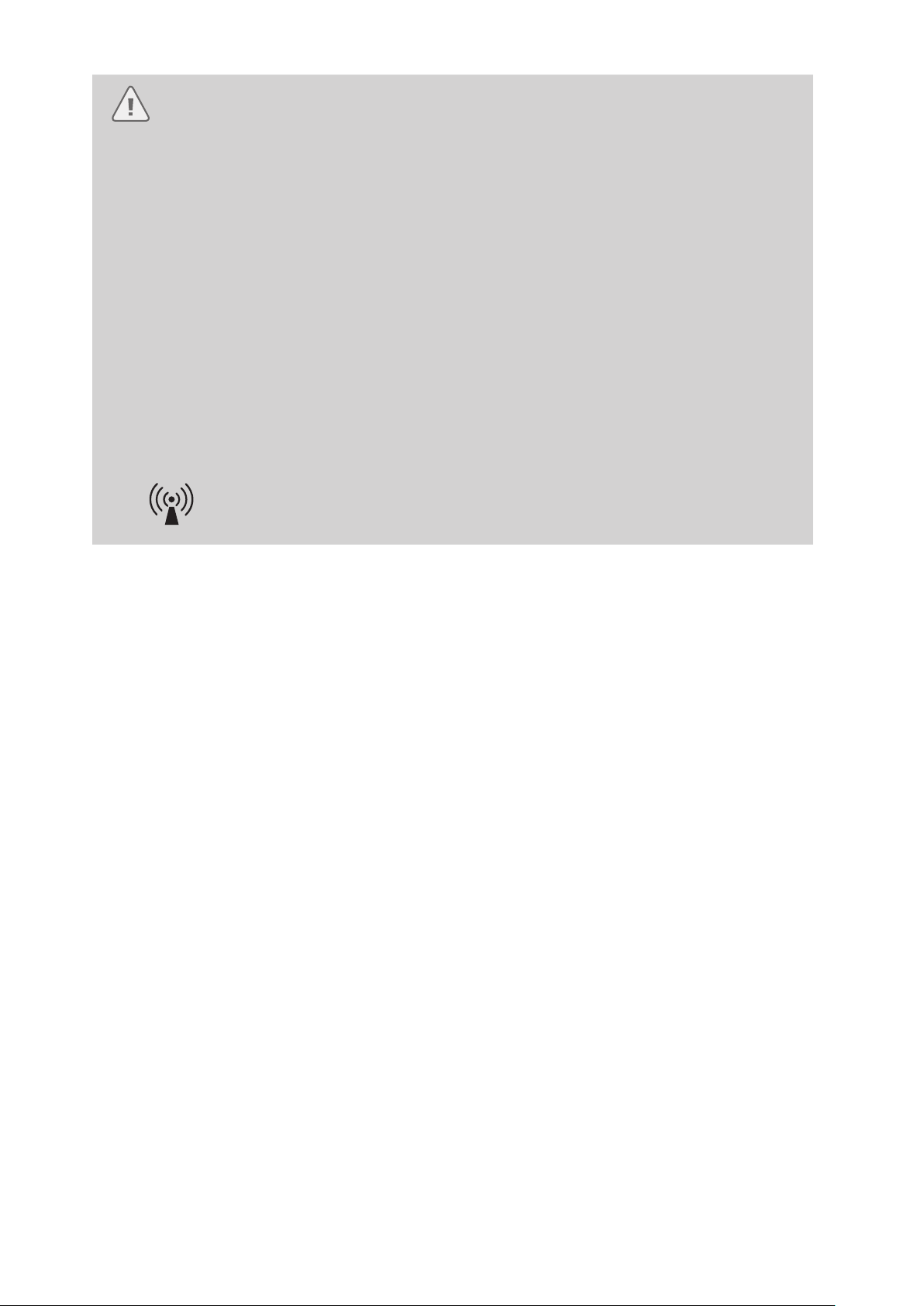
• Electromagnetic interference may occur with equipment labeled with the following symbol
or near mobile RF communication equipment such as mobile phones. If electromagnetic
interference occurs, reorient or relocate the endoscope or shield the location of use.
Maintenance management
The service life of this endoscope is 6 years after date of shipment with the following conditions.
• Perform inspection before use, care after use, storage, and replacement of consumables according to
this IFU.
• Have a specialist specified by PENTAX Medical perform repairs and at least annual periodic inspections.
13
Page 16
1
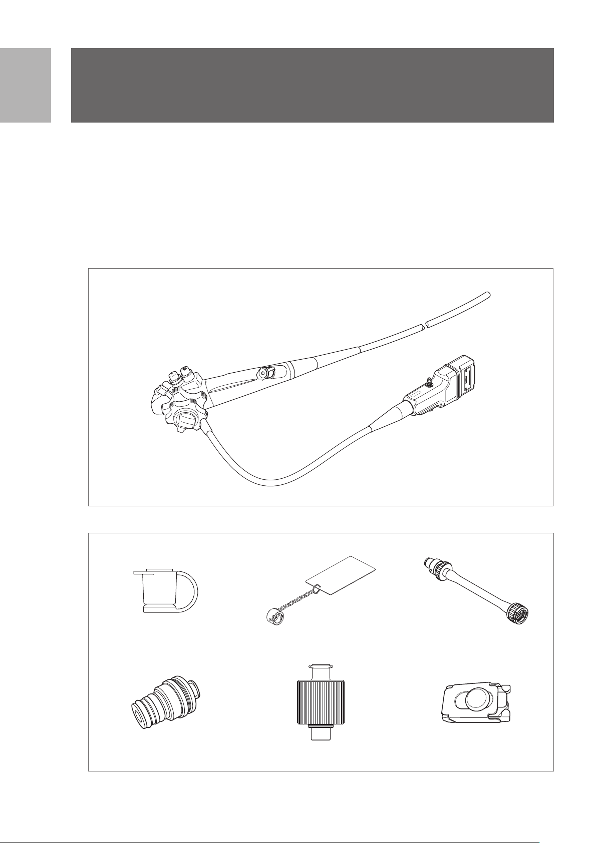
1
Package contents
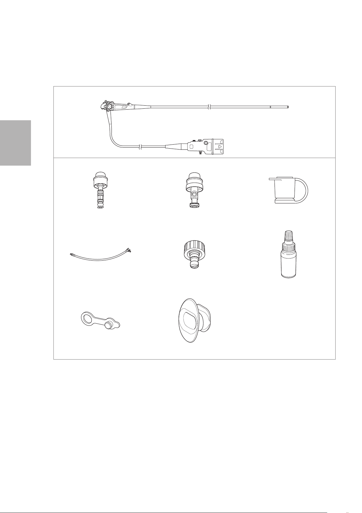
Package contents
1-1. Package contents
Check the package contents according to the separate Standard Accessories List provided with this
product. For detail picture of the contents/accessories, refer to Figure 1.1 and 1.2.
If there are any damaged or missing components, do not use the endoscope. Immediately contact your
local PENTAX Medical service facility.
Endoscope
EG29 - i10c
Figure 1.1
Accessories
Inlet Seal (OF - B190)
(Installed)
Cleaning Adapter (OF - G17) Cleaning Adapter for Water Jet
Figure 1.2
Ventilation Cap (OE- C28) Venting Connector Adapter (OE- C29)
Connector (OE - C20)
Cleaning Adapter
(OF - B153)
14
Page 17
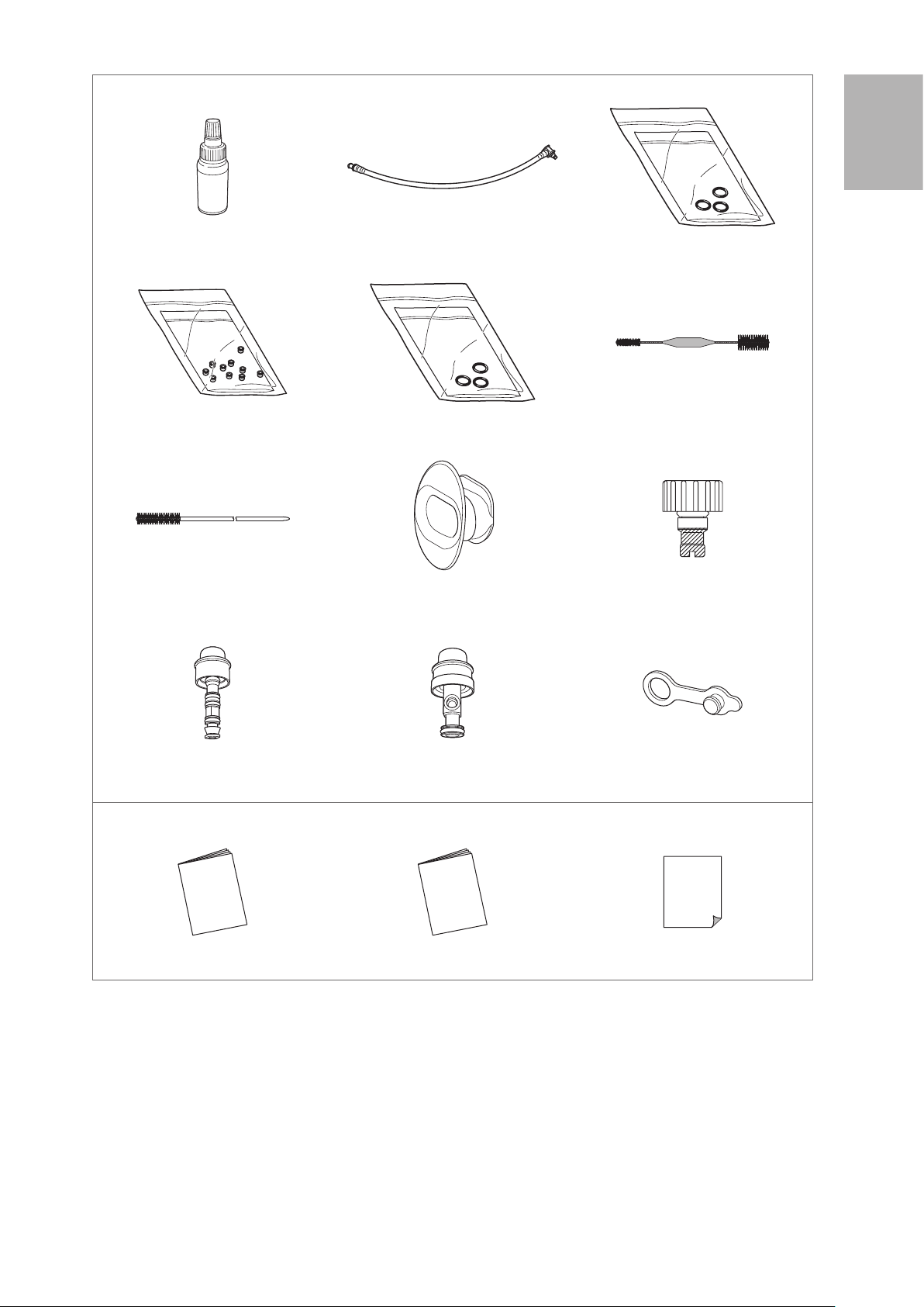
Accessories
Silicone Oil (OF - Z11) Irrigation Tube (OF - B113) O Ring Set (OF -B192*)
* For Air/ Water Feeding Valve (OF- B188)
1
Package contents
Check Valve Sets (OE- C15) O Ring Set (OF - B127**)
** For Suction Control Valve (OF - B120)
Cleaning Brush (CS5522A) Bite Block (OF-Z5) Water Jet Check Valve Adapter
Air/ Water Feeding Valve (OF - B188)
(Installed)
Others
Suction Control Valve (OF- B120)
(Installed)
Cleaning Brush (CS - C13A)
(OE - C12) (Installed)
Water Jet Connector Cap (OF- B118)
(Installed)
IFU (Operation; this document) IFU (Reprocessing) Standard Accessories List
Figure 1.2
15
Page 18
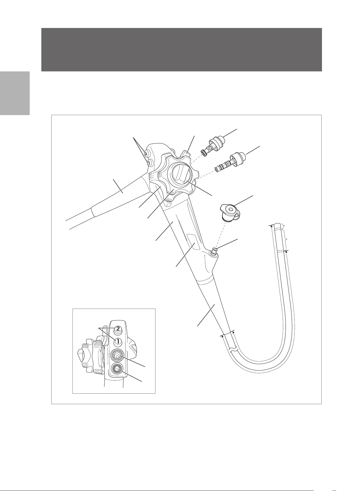
2
7
2
Nomenclature and functions
2-1. Control body and insertion portion
Nomenclature and functions
1
10
3
9
Alternative view
1
2
4
Control Body
13
5
10
12
11
Insertion Portion
(Endoscope
components that
come into direct
contact with the
patient.)
Distal End
Bending
Section
Figure 2.1
16
6
8
Insertion Tube
Page 19

1. Remote Buttons 1- 4
Functions assigned to each button can be remotely controlled by pressing each of the remote buttons.
Functions of the remote buttons 1- 4 are assigned from the video processor.
Refer to the IFU of the video processor for assignment of functions to each remote button.
2. Up / Down Angulation Control Knob
By turning in the “▲U” direction, the bending section moves upwards.
By turning in the “▲D” direction, the bending section moves downwards.
3. Up / Down Angulation Lock Lever
By turning counterclockwise, upward/downward bending of the bending section is locked.
By turning in the “F ►” direction, the bending lock is released.
4. Right /Left Angulation Control Knob
By turning in the “▲R” direction, the bending section moves to the right.
By turning in the “▲L” direction, the bending section moves to the left.
5. Right /Left Angulation Lock Knob
By turning counterclockwise, right / left bending of the bending section is locked.
By turning in the “F ►” direction, the bending lock is released.
6. Suction Cylinder
Attach the suction control valve (OF- B120).
7. Suction Control Valve (OF- B120)
Attach to the suction cylinder. Depress it to suction fluids or air through the instrument channel of the
endoscope.
8. Air / Water Feeding Cylinder
Attach the air/water feeding valve (OF - B188) or the optionally available gas/ water feeding valve (OF-
B194).
9. Air / Water Feeding Valve (OF-B188)
Attach to the air/water feeding cylinder. Covering the hole on the valve button feeds air to the air/ water
nozzle at the distal end of the endoscope. Depressing the valve button feeds water to the air/ water
nozzle at the distal end of the endoscope.
10. Strain Relief Boot
The strain relief boot protects the connecting parts.
11. Instrument Channel Inlet
The instrument channel inlet is an inlet for endoscopic devices. Attach the inlet seal (OF- B190).
12. Inlet Seal (OF - B190)
The inlet seal is attached to the instrument channel inlet to avoid fluid / air leakage.
13. Model Name Label
The model name label shows the model name, minimum instrument channel width, and other related
information.(Figure 2.2)
2
Nomenclature and functions
EG29-i10c
Figure 2.2
Minimum Instrument Channel Width
3.2
Model Name
17
Page 20
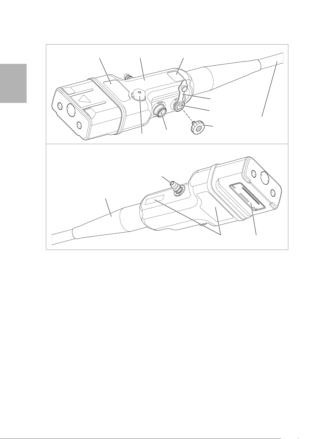
2-2. Scope connector
2
Model Name
Country of Origin
Nomenclature and functions
Alternative view
10
Scope Connector
18
14
Serial Number
Date of Manufacture
Water Jet Connector Cap
(OF - B118)
16
Umbilical Cord
17
15
Electrical ContactsManufacturer Label
Figure 2.3
14. Suction Nipple
Connect the suction tube on the suction source to the suction nipple.
15. Air/ Water Port
Connect the air/ water feeding hose on the water bottle assembly to the air/ water port.
16. Water Jet Port
Attach a water jet check valve adapter (OE- C12).
1 7. Water Jet Check Valve Adapter (OE- C12)
Use it by attaching to the water jet port.
Connect the irrigation tube (OF- B113) to send sterile water from a syringe or irrigation pump to the
water jet nozzle at the distal end of the endoscope.
When an irrigation tube is not connected, close it with the water jet connector cap (OF- B118).
18. Venting Connector
Attach the ventilation cap (OE- C28) or leakage tester via the venting connector adapter (OE - C29)
here.
18
Page 21

3
Before use, the endoscope, accessories, video processor, and other components must be prepared and
carefully inspected according to the IFU. Any equipment used in combination with the endoscope must also
be prepared and inspected according to the respective instruction manuals.
Always perform pre - use inspection before each use.
Preparation and inspection
Refer to “5 -1. Troubleshooting guide” (p. 76) for assistance in diagnosing an endoscope malfunction. If the
problem persists after troubleshooting or there is an apparent failure, do not use the endoscope. Send it for
repair according to “5- 3. Returning the endoscope for repair” (p. 80).
Warning
• Always perform pre - use inspection before each use. NEVER use an endoscope with a suspected
abnormality. Doing so may result in malfunction, endoscope damage, and / or injury to the patient
and / or user.
• Ensure that another endoscope is also prepared to avoid interruption of the procedure due to
endoscope failure or unforeseen events.
3
Preparation and inspection
19
Page 22
3
3-1. Preparation of the equipment
Prepare the endoscope, accessories, ancillary equipment, and protective equipment. Refer to the
“Compatible products” to prepare the ancillary equipment as necessary and to the IFU provided with the
video processor for its inspection.
Endoscope
Accessories
Preparation and inspection
Air/ Water Feeding Valve (OF - B188) Suction Control Valve (OF- B120) Inlet Seal (OF- B190 or OF - B215*)
* Optional item
Irrigation Tube (OF - B113) Water Jet Check Valve Adapter (OE- C12) Silicone Oil (OF- Z11)
Water Jet Connector Cap (OF- B118) Bite Block (OF-Z5)
20
Page 23
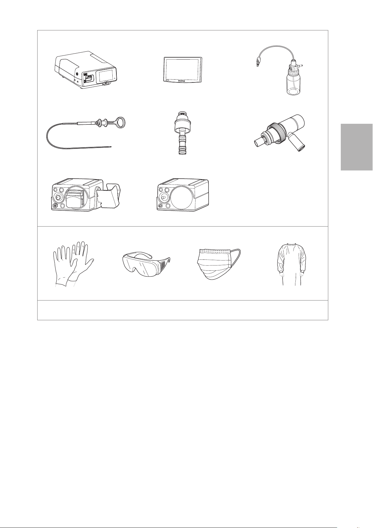
Ancillary Equipment
Video Processor Monitor Water Bottle Assembly
Endoscopic Device Gas / Water Feeding Valve (OF- B194*)
* Optional item
3
Gas Adapter (OF - G11*)
* Optional item
Suction Source
Irrigation Pump (EGA- 500P)
Protective Equipment (example)
Gloves Goggles Mask Medical Gown
Other Equipment
Gauze, sterile water, container for sterile water, etc.
Figure 3.1
CO² Insufflator (EGA - 501P)
Preparation and inspection
21
Page 24
3
3-2. Inspection of the endoscope
Prepare an endoscope that has been reprocessed according to the procedure specified in the separate
IFU(Reprocessing) of this endoscope.
Warning
• NEVER disassemble or modify the endoscope. Doing so may impair its original functionality
and possibly result in serious injury to the patient and /or user.
• NEVER use an endoscope with any abnormality. Doing so may result in endoscope damage,
detachment of parts into the patient’s body cavity, malfunction during use, and / or injury to
the patient and / or user.
• Use only sterile water for inspection. Failure to do so may result in contamination of the
endoscope with waterborne bacteria and other microorganisms. Do NOT use water that has
been left uncovered for a prolonged period of time.
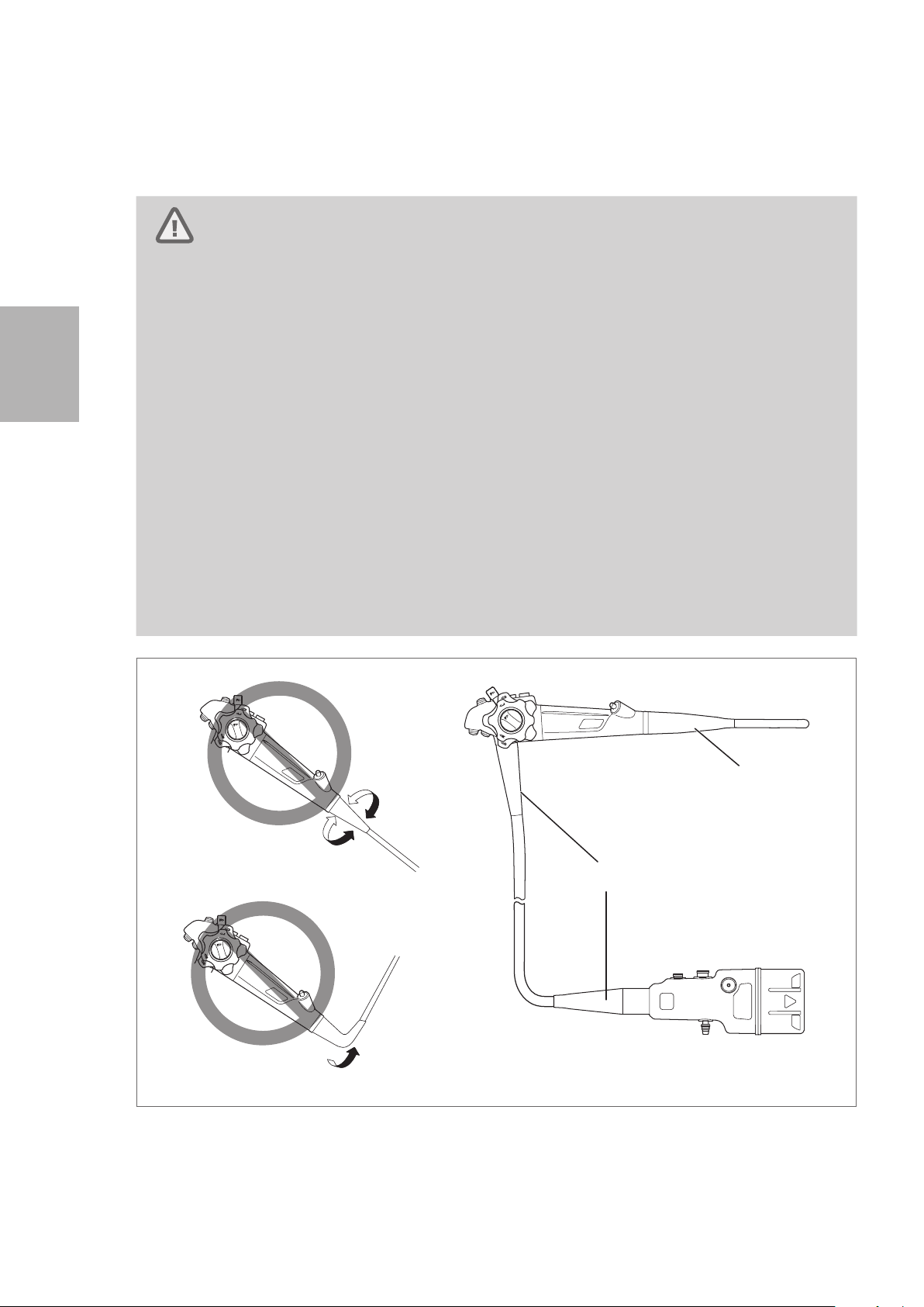
Preparation and inspection
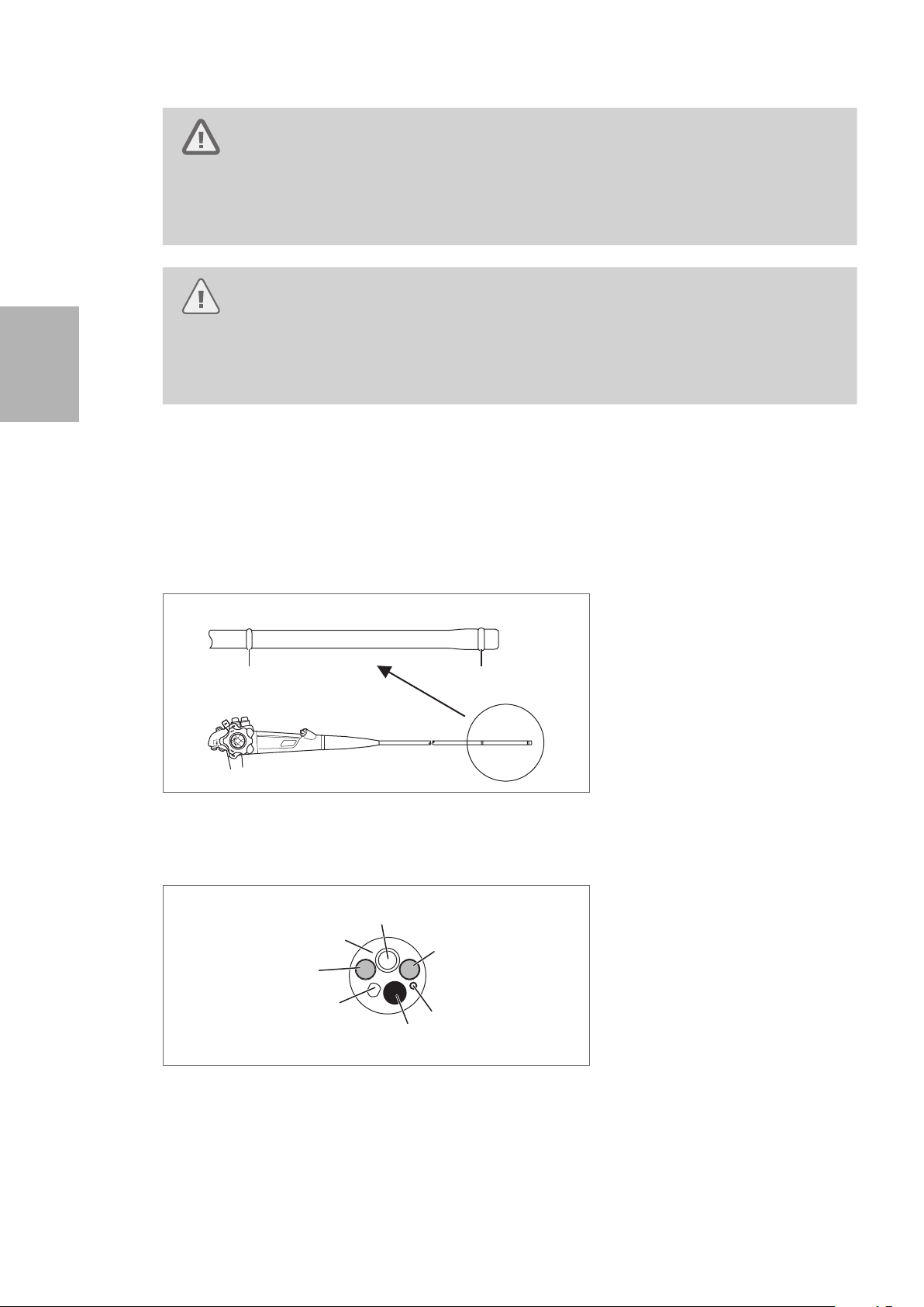
• Do NOT excessively twist, bend, or rotate any of the strain relief boots on the instrument (See
Figure 3.2 (A) and (B)) to identify the strain relief boots). Doing so may result in instrument
damage. Pay special attention to the careful handling of the strain relief boot of the insertion
portion (See Figure 3.2 (A)) of the endoscope, because it has a small diameter and is more
likely to suffer damage due to mishandling.
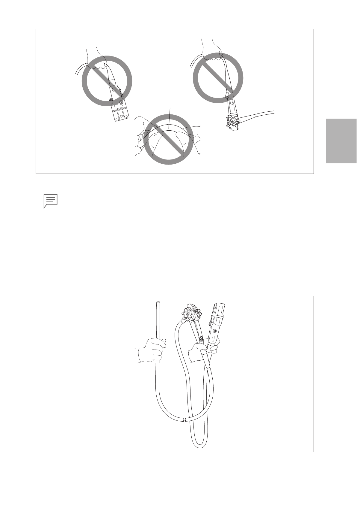
• When carrying the endoscope, do NOT grasp or carry it only by its umbilical cord or insertion
portion. Moreover, do NOT squeeze or forcefully bend the bending section. (Figure 3.3) Doing
so may result in equipment damage.
Figure 3.2
(A)
Do Not Twist or Rotate
(B)
Do Not Forcefully Bend
22
Page 25
Bending Section
Do Not
Forcefully
Bend
Figure 3.3
Note
In case the endoscope is hot / cold immediately after cleaning, high -level disinfection, and/ or
sterilization, wait until it returns to room temperature before using it. Lens fogging, which will
result in blurry images, might result from abrupt changes in environmental temperature.
█
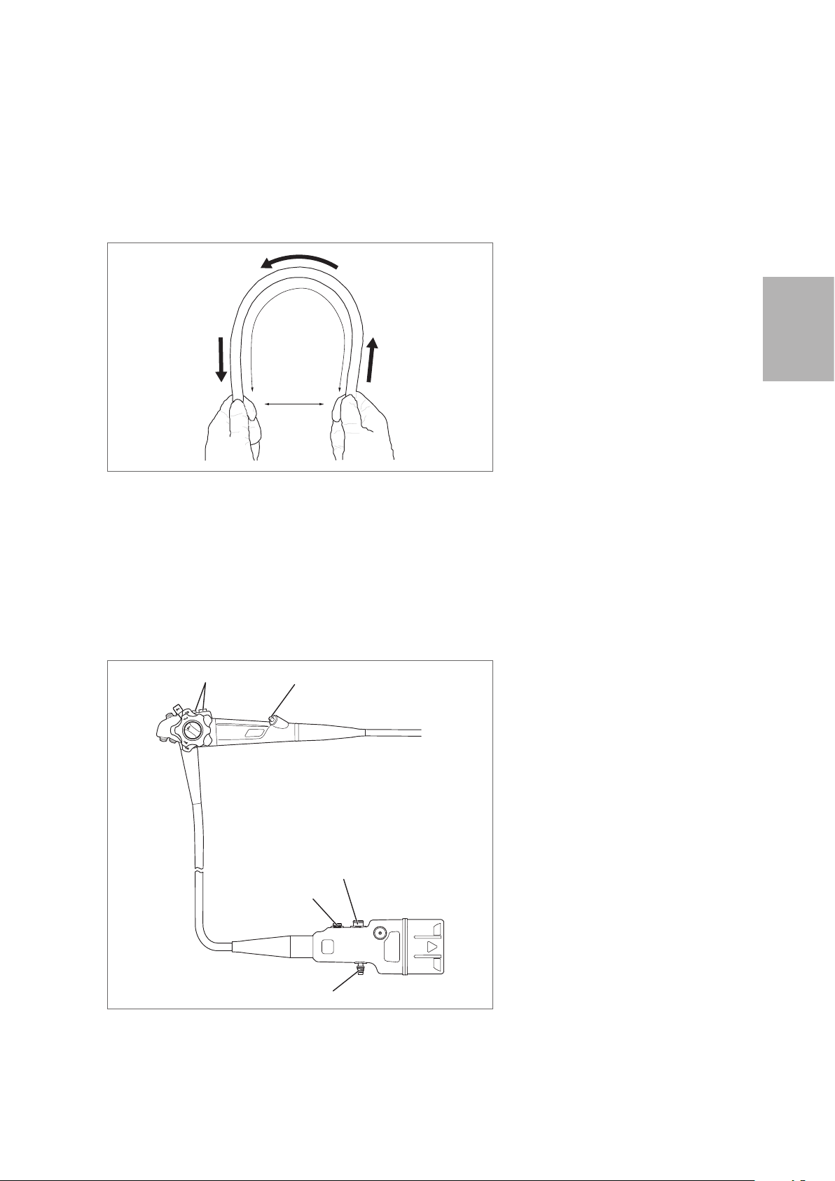
Carrying the endoscope by hand
When carrying the endoscope by hand, loosely loop the umbilical cord and insertion portion, hold the
control body and the scope connector in gloved hand, and hold insertion portion (near the bending
section) in the other gloved hand as shown in Figure 3.4.
3
Preparation and inspection
Figure 3.4
23
Page 26
3
(1)
(2)
(6)
(5)
Inspection of the entire endoscope
Warning
NEVER use the endoscope with any abnormality in function. Doing so may result in endoscope
damage, detachment of parts into the patient’s body cavity, endoscope malfunction during
use, and / or injury to the patient and / or user.
Caution
Clear images can NOT be obtained if there is any foreign material attached to the objective
lens or light guides. Water vapor from the foreign material may be released in response to
heating by the light passing through these components, obscuring the image.
Preparation and inspection
1. Check the entire surface of the endoscope for any visible adhered material.
2. Check the entire surface of the insertion portion for abnormalities such as wrinkles, scars, sharp
edges, clouding of the surface, dents, catching, protrusions, attachment of foreign materials,
detachment of parts, etc.
3. Check the surface of the adhesive bands on both ends of the bending section for abnormalities
such as scratches, clouding, and peeling. With clean gauze, lightly wipe the surface of the adhesive
bands to ensure that there is no catching and/or attachment of the adhesive to the gauze.
Bending Section
Magnified View
(1)
Figure 3.5
4. Check the case of the distal end of the endoscope (especially around the periphery of the instrument
channel) for any abnormalities such as deformation or chipping.
(1)
(1) Adhesive Bands
24
(1) Objective Lens
(2) Light Guides
(4)
(3)
Figure 3.6
5. Check the objective lens at the distal end of the endoscope and the light guides for any abnormalities
such as attachment of foreign material, scratches, or chipping, and ensure that there is no gap on
the periphery of the lens.
6. Ensure that there are no scratches, clouding, or peeling on the surface of the adhesive glue around
the objective lens at the distal end of the endoscope and that it has a glossy surface.
(2)
(3) Air/ water Nozzle
(4) Case
(5) Instrument Channel
(6) Water Jet Nozzle
Page 27
7. Gently clean the objective lens and light guides with clean gauze or a cotton- tip applicator moistened
(5)
(1)
with 70% – 90% medical grade ethyl or isopropyl alcohol. Check that there is no attachment of the
adhesive to the gauze.
8. Check the air/ water nozzle at the distal end of the endoscope for any abnormalities such as
clogging, dents, deformations, chipping, etc.
9. Using both hands, form an arch with the insertion tube as shown in Figure 3.7. Slide the insertion
tube in the direction of the arrows in Figure 3.7, and check that the entire insertion tube can be bent
smoothly and easily to form an arch.
Approx. 30 cm
Approx. 20 cm
Figure 3.7
3
10. Check the entire surface of the umbilical cord for abnormalities such as wrinkles, scars, sharp
edges, clouding of the surface, catching, protrusions, attachment of foreign materials, detachment
of parts, etc.
11. Check the control body, scope connector, and electrical contacts for abnormalities such as
scratches, deformities, loose parts, etc. Pay special attention when checking the parts shown in
the Figure 3.8. Using a clean lint- free cloth, gently hold these parts and move them in various
directions to ensure that there are no abnormalities such as looseness.
(2)
(4)
(3)
(1) Suction Cylinder & Air/ Water
Feeding Cylinder
(2) Instrument Channel Inlet
(3) Water Jet Port
(4) Air/ Water Port
(5) Suction Nipple
Preparation and inspection
Figure 3.8
25
Page 28

12. Check the electrical contacts for any attachment of foreign materials such as residual chemical
solution, water deposit, sebum, dust and gauze lint, etc.
Note
In case there are any attachment of foreign material or the endoscope has been left unused
for a prolonged period of time, wipe the electrical contacts with gauze moistened with
70% – 90% medical grade ethyl or isopropyl alcohol. After wiping, dry the electrical contacts
sufficiently.
13. Ensure that the electrical contacts are sufficiently dry.
3
Inspection of the angulation mechanism
Ensure that there is nothing near the bending section that would hinder its operation, and inspect the
angulation mechanism while the insertion portion is kept straight.
Preparation and inspection
█
Inspection of bending function
Warning
Do NOT use an endoscope that can NOT be smoothly angulated, can NOT be fully angulated
in any direction, or has excessive play in the angulation control lever. Use of an endoscope
with any of these conditions may result in damage to the device, malfunction during use,
and / or patient injury.
1. Turn the up / down angulation lock lever and right / left angulation lock knob in the “F ►” direction
until they stop to release the lock of the angulation control knobs.
26
Figure 3.9
Page 29
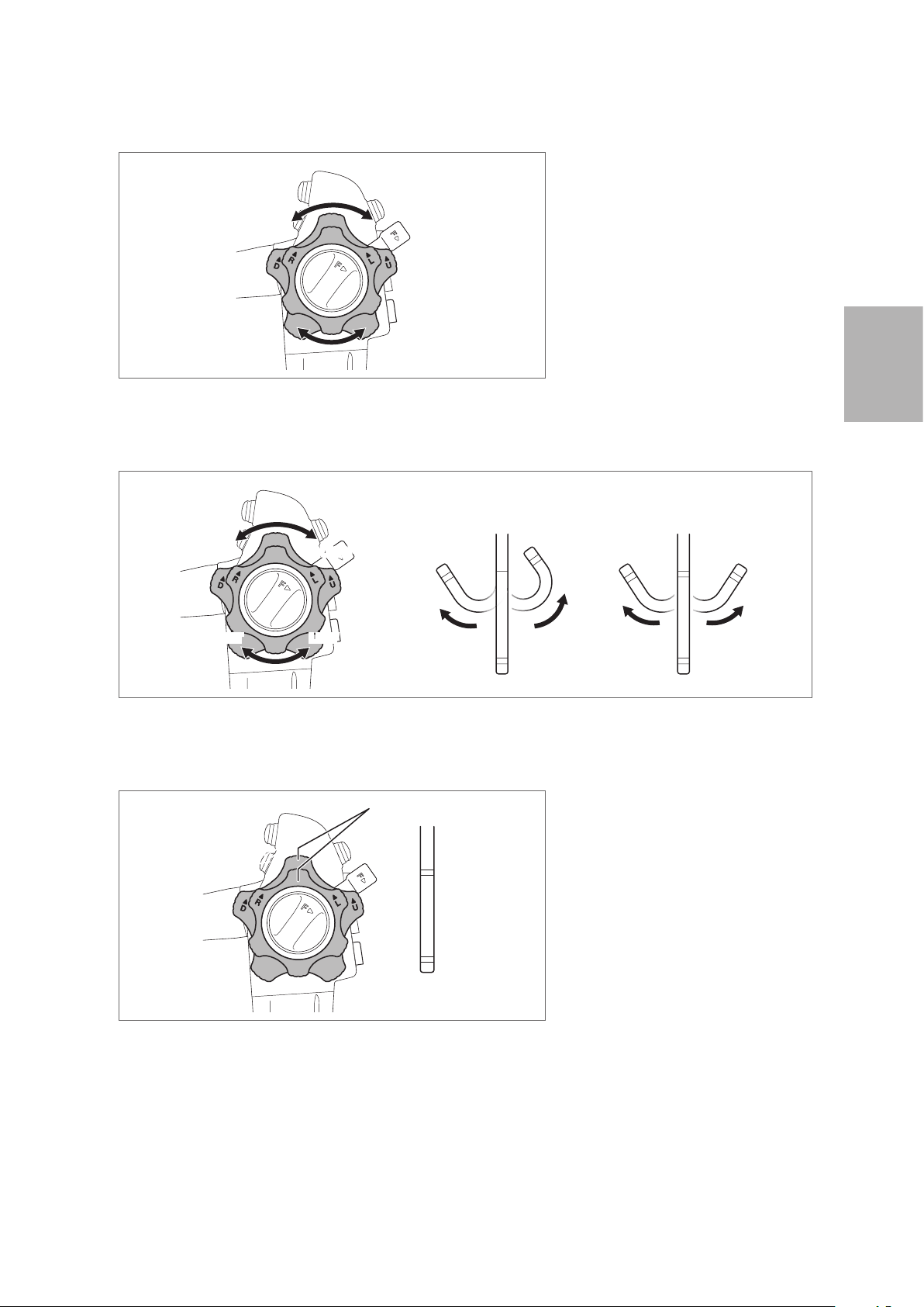
2. Turn the up/down and right/ left angulation control knobs slowly in each direction until they stop,
and return them to their original position. Check that the angulation control knobs operate smoothly
with no roughness or catching.
Figure 3.10
3. Check that the bending section angulates in the direction in which the angulation control knobs are
turned and that the maximum angulation can be achieved.
UP
RIGHT
Figure 3.11
4. Turn the angulation control knobs back to the neutral position. Check that the bending section
returns to a straight orientation.
DOWN
LEFT
DOWN LEFT
Neutral Position
UP RIGHT
3
Preparation and inspection
Figure 3.12
27
Page 30

█
Inspection of the up/down bending lock mechanism
1. Turn the up / down angulation lock lever counterclockwise until it stops.
3
Figure 3.13
2. Turn the up/down angulation control knob slowly in the “▲U” or “▲D” direction until it stops.
Preparation and inspection
Figure 3.14
3. Check that the curved form of the bending section is fixed when releasing the angulation control
knob.
4. Turn the up/down angulation lock lever in the “F ►” direction until it stops to release the lock.
Check that the bending section returns to a straight orientation.
28
Figure 3.15
Page 31

█
Inspection of the right / left bending lock mechanism
1. Turn the right /left angulation lock knob counterclockwise until it stops.
Figure 3.16
2. Turn the right/ left angulation control knob slowly in the “▲R” or “▲L” direction until it stops.
Figure 3.17
3. Check that the curved form of the bending section is fixed when releasing the angulation control
knob.
4. Turn the right/ left angulation lock knob in the “F ►” direction until it stops to release the lock.
Check that the bending section returns to a straight orientation.
3
Preparation and inspection
Figure 3.18
29
Page 32

3
3-3. Inspection of accessories and attachment to the endoscope
When using reusable accessories, ensure that they have been cleaned, high- level disinfected, and/or
sterilized according to the separate IFU (Reprocessing) for this endoscope.
Warning
NEVER disassemble or modify the accessories and endoscopic devices. Doing so may impair
their original functionality and possibly result in serious injury to the patient and /or user.
Preparation and inspection
30
Page 33

Inspection of the air/water feeding valve (OF-B188)
(3)
(1)
(2)
Warning
Replacement O - rings are NOT sterilized or disinfected before shipment. Perform cleaning
and high - level disinfection and/or sterilization of the air/ water feeding valve after O - ring
replacement.
Caution
• If any abnormality is detected with the check valve of air/ water feeding valve (OF - B188)
(Figure 3.19), replace the air/ water feeding valve with a new one. Use of an air/ water
feeding valve with abnormalities can result in continuous air feeding into the patient,
posing a risk of pain and / or perforation. Dispersal of patient material into the environment
can also occur, posing a risk of infection to healthcare providers.
• The O - ring of the air/ water feeding valve is a consumable. If any abnormality is detected
with the O - ring, stop using it immediately and replace it with a new one. Use the
compatible O - ring set for replacement. Using an O - ring with abnormalities or non -
compatible O - ring could lower the function of air/ water feeding, cause unintended
continuous air feeding, and pose a risk of pain to the patient. Dispersal of patient material
into the environment can also occur, posing a risk of infection to healthcare providers.
3
Note
• Use O ring set (OF - B192) to replace the O- ring of air / water feeding valve (OF- B188).
• For details on the O - ring replacement method, refer to the IFU provided with the O ring
set (OF - B192).
(1) O -ring
(2) Check Valve
(3) Hole
Air/ Water Feeding Valve (OF - B188)
Figure 3.19
1. Check the air/ water feeding valve (OF- B188) for any abnormalities such as attachment of foreign
materials, deformation, cracks, or hole blockage.
2. Check that the O- ring is properly attached and that there is no chipping, breaks, or peeling in the
O - ring or check valve.
Preparation and inspection
31
Page 34

3
(1)
(3)
(2)
Inspection of the suction control valve (OF-B120)
Warning
• If any abnormality is detected with the rubber seal of suction control valve (OF- B120)
(Figure 3.20), replace the suction control valve with a new one. Use of a suction control
valve with any abnormality can result in continuously weak aspiration, which may hinder
the procedure. Dispersal of patient material into the environment can also occur, posing
a risk of infection to healthcare providers.
• The O - ring of the suction control valve is a consumable. If any abnormality is detected
with the O - ring, stop use immediately and replace it with a new one. Use the compatible
O - ring set (OF - B127) for O - ring replacement. Using an O -ring with abnormalities or
non - compatible O - ring could result in unintended continuous suction and may hinder
the examination. It could also pose a risk of infection to the user as a result of reflux or
dispersal of patient’s body fluids from the suction control valve.
Preparation and inspection
• Replacement O - ring is NOT sterilized or disinfected before shipment. Perform cleaning
and high - level disinfection, and/or sterilization of the suction control valve after O - ring
replacement.
Note
Use the O ring set (OF - B127) to replace the O- ring of the suction control valve (OF - B120).
(1) Rubber Seal
(2) O - ring
(3) Hole
Suction Control Valve (OF- B120)
Figure 3.20
1. Check the suction control valve (OF - B120) for any abnormalities such as attachment of foreign
materials, deformation, cracks, or hole blockage.
2. Check that the O- ring is properly attached and that there is no chipping, breaks, or peeling in the
O - ring or the rubber seal (Figure 3.20).
32
Page 35

Inspection of the inlet seal (OF- B190)
(1) (2)
(4)
Warning
NEVER use an inlet seal (OF - B190) that has any abnormality. Replace it with a new one.
Inlet seals are consumables. Using a damaged and / or worn inlet seal may result in lowered
suction function and potential reflux or dispersal of patient’s body fluids, posing a risk of
infection to the user.
1. Check the slit in the cap of the inlet seal (OF- B190) and the hole of the body of the inlet seal for
any abnormalities such as cracks, wear, chipping, and attachment or presence of foreign materials.
Check that the light does not shine through the slit of the cap.
(3)
Inlet Seal (OF - B190)
Figure 3.21
2. Close the inlet seal as depicted in Figure 3.22.
(1) Hole
(2) Slit
(3) Body
(4) Cap
3
Preparation and inspection
Figure 3.22
PENTAX Medical PROfILE Single Use Endoscope Inlet Seal (OF- B215) can also be used. For
details on the inspection method, refer to the IFU provided with the inlet seal (OF- B215).
Correct Incorrect
Note
33
Page 36

3
(2)
(3)
Inspection of the water jet check valve adapter (OE- C12)
Warning
Replacement check valve sets (OE- C15, a packed set of multiple check valves) are NOT
sterilized or disinfected before shipment. Perform cleaning and high- level disinfection or
sterilization of the water jet check valve adapter after check valve replacement.
Caution
NEVER use a check valve of the water jet check valve adapter (OE- C12) that has any
abnormality. Replace it with a new one. Check valves are consumables. Using a damaged
check valve may result in potential reflux or dispersal of patient’s body fluids, posing a risk of
infection.
Preparation and inspection
Note
Use the check valve set (OE- C15, a packed set of multiple check valves) for replacement.
(1) O -ring
(2) Hole
(1)
Water Jet Check Valve Adapter (OE- C12)
Figure 3.23
1. Check the water jet check valve adapter for any abnormalities such as attachment of foreign
materials, deformation or cracks, or hole blockage.
2. Ensure that the check valve is attached correctly to the water jet check valve adapter without any
gaps or pinching.
(3) Check Valve
Figure 3.24
3. Check the O- ring and check valve for any abnormalities such as cracks, breaks, and peeling.
34
Page 37

Inspection of the irrigation tube (OF- B113)
Warning
NEVER use the irrigation tube (OF- B113) when an abnormality is suspected in inspection.
Replace it with a new one. Using the OF- B113 with abnormality in the process of cleaning,
high level disinfection, or sterilization may cause leaking of detergent from the connection
part and detachment of the OF- B113. The cleaning, high -level disinfection or sterilization may
not be effective due to the insufficient reprocessing.
(1) Luer Connector
(1)
(2)
(2) Hole
(3) Connector
(4) Hole
(5) O - ring
3
(3)
(4)
(5)
Irrigation Tube (OF - B113)
Figure 3.25
1. Check the entire surface of the irrigation tube (OF- B113) for abnormalities such as bending/
breakage/ looseness of the connector, cut / chip of the O - ring, buckling/deterioration / hardening
of the tube, and/or broken luer.
2. Attach a syringe filled with the sterile water to the luer connector of the irrigation tube (OF- B113)
and flush sterile water through the tube.
3. Check that sterile water flows in a steady stream from the connector of the irrigation tube (OF -
B113).
Preparation and inspection
35
Page 38

3
Inspection of the bite block (OF-Z5)
Caution
NEVER use a bite block with any abnormality. Replace it with a new one.
Using a bite block with an abnormality may result in endoscope damage and injury to the oral
cavity of patients.
Check the bite block for any abnormalities such as attachment of foreign materials, cracks, deformity,
chipping, and discoloration.
Preparation and inspection
Bite Block (OF-Z5)
Figure 3.26
36
Page 39

Inspection of the endoscopic devices
For details on the inspection of each endoscopic device, refer to the instruction manual provided
with the specific endoscopic device. For reusable endoscopic devices, prepare ones that have been
cleaned and sterilized by following the instruction manual for the respective endoscopic device.
Warning
• NEVER use an endoscopic device with signs of damage and/or operational abnormality.
Doing so may result in malfunction during use, endoscope damage, and/or patient injury.
• Use endoscopic devices specified by PENTAX Medical whose compatibility has been
confirmed. Using endoscopic devices whose compatibility has not been confirmed may
result in endoscope damage and / or patient injury caused by failure during use.
This section describes the use of a biopsy forceps.
1. Check the entire surface of the forceps for any visible adhered material.
2. Check the insertion portion and control body of the biopsy forceps for abnormalities such as
wrinkles, scars, sharp edges, clouding of the surface, dents, catching, protrusions, attachment of
foreign materials, falling of parts, etc.
Control Body
Insertion Portion
Figure 3.27
3. Check that the cups of the biopsy forceps open/ close smoothly by operating its handle.
CLOSE
CLOSE
OPEN
3
Preparation and inspection
OPEN
Figure 3.28
37
Page 40

4. Form a loop with a diameter of 20 - 30 cm with the flexible shaft at approximately 20 - 30 cm from
the tip of the insertion portion of the biopsy forceps. Check that the cups of the biopsy forceps
open / close smoothly by operating its handle.
20cm - 30cm
20cm - 30cm
3
Figure 3.29
5. Check that the cups align with each other when closed.
Preparation and inspection
Figure 3.30
38
Page 41

Attachment of accessories
(1)
(2)
Warning
Attach the accessories properly to the endoscope. Failure to do so may result in lowered
function and potential reflux or dispersal of patient’s body fluids, posing a risk of infection to
the user.
█
Attachment of the air/water feeding valve (OF - B188) and suction control valve (OF- B120)
Warning
• Ensure to apply silicone oil lubricant (OF - Z11) onto the O- ring of each valve and the
rubber seal of the suction control valve (OF- B120). Using the valves without applying the
oil or applying a silicone oil other than the specified one could deteriorate the functions
and may result in damage to the endoscope and/or patient injury.
• Attach the air/water feeding valve (OF - B188) and suction control valve straight into
their respective valve cylinders. Inserting them into their valve cylinders at an angle may
damage valve O- rings and rubber seals.
(1) O -ring
(2) Rubber Seal
(1)
Air/ Water Feeding Valve
(OF - B188)
Figure 3.31
1. Apply a minimal amount of silicone oil lubricant (OF-Z11) to the O- rings of the air / water feeding
valve (OF- B188) and the O - ring and rubber seal of the suction control valve (OF- B120). In order to
apply the silicone lubricant, place a small droplet of oil onto a sterile gloved forefinger, gently swirl
the oil between the thumb and the forefinger, and apply it onto the necessary parts. Wipe off the
excess lubricant with soft gauze.
2. Attach the air/ water feeding valve to the air/ water feeding cylinder of the endoscope.
Suction Control Valve
(OF - B120)
3
Preparation and inspection
Figure 3.32
39
Page 42

3. Ensure that the air/ water feeding valve (OF- B188) is firmly attached. Press down the air/ water
(1) (2)
feeding valve a few times to ensure that it moves smoothly.
Figure 3.33
3
4. Align the metal tab on the shaft of the suction control valve with the notch on the suction cylinder
of the endoscope.
(1) Notch
Preparation and inspection
Figure 3.34
5. Attach the suction control valve (OF- B120) to the suction cylinder of the endoscope.
(2) Metal Tab
Figure 3.35
6. Check that the suction control valve is firmly attached. Press down the suction control valve a few
times to ensure that it moves smoothly.
Figure 3.36
40
Page 43

█
Attachment of the inlet seal (OF - B190 or OF - B215 (option))
1. Attach the inlet seal (OF - B190 or OF- B215 (option)) to the instrument channel inlet.
Figure 3.37
2. Ensure that the inlet seal is tightly attached to the instrument channel inlet without gaps.
Correct
Figure 3.38
█
Attachment of the water jet check valve adapter (OE- C12) and water jet connector cap (OF - B118)
1. Attach the water jet connector cap (OF- B118) and water jet check valve adapter (OE- C12) to the
water jet port of the endoscope.
Incorrect
Gap
3
Preparation and inspection
Figure 3.39
2. Ensure that the water jet check valve adapter is fi rmly attached to the water jet port without gaps.
(Close the lid of the water jet connector cap.)
Figure 3.40
41
Page 44

3
3-4. Inspection and connection of ancillary equipment to the endoscope
Inspect the ancillary equipment prepared in “3 -1. Preparation of the equipment”, such as the video
processor, monitor, and suction source, according to their respective IFU.
Video processor
Monitor
Suction source
Endoscopic device
Water bottle assembly
Irrigation pump
CO² Insufflator, etc.
Inspection of the video processor
Preparation and inspection
Only use compatible PENTAX Medical video processors.
For compatible video processors, refer to “Compatible products” (p. 8) or “System chart” (p. 90).
For details on the preparation and inspection of the video processor, refer to the IFU of the respective
video processor.
42
Page 45

Connection of the endoscope and ancillary equipment
█
Connection to the video processor
Warning
Ensure that the scope connector is securely attached to the video processor. Failure to do so
may result in an abnormality such as disappearance of the image which may cause patient
injury.
Caution
Ensure that the scope connector (including the electrical contacts) is sufficiently dry before
connecting it to the video processor. In addition, check the electrical contacts for any
attachment of foreign materials (such as residual chemical solution, water deposit, sebum,
dust and gauze lint, etc.) before connecting. Failing to do so may result in the endoscope’s
malfunction or failure.
Note
When connecting the scope connector to the video processor, hold the video processor with
one hand. It may become difficult to connect if the video processor moves.
1. Ensure that all ancillary equipments are turned off.
2. Hold the scope connector as shown in Figure 3.41, and turn the scope connector's Connector UP
index ("▲") upward and push the scope connector into the video processor receptacle until it clicks.
(1) UP index
(1)
3
Preparation and inspection
Figure 3.41
43
Page 46

█
Connection of the water bottle assembly, suction tube, and irrigation tube (OF - B113)
Warning
• Use only sterile water in the water bottle assembly. Failure to do so may pose a risk of
infection.
• Do NOT use defoaming agents in the water bottle assembly. These agents attach to the
internal lumen of the air/ water channel and may block the channel and/or damage the
endoscope. They are also extremely difficult to remove during subsequent cleaning and
can interfere with proper endoscope reprocessing.
3
Caution
Connect the suction tube of the suction source firmly to the suction nipple. Failure to do
so may result in disconnection of the suction tube during use and pose a risk of cross
Preparation and inspection
contamination to the user as a result of reflux or dispersal of patient’s body fluids.
Note
Turn off the air/ water feeding pump of the video processor beforehand.
1. Attach the water bottle assembly correctly according to the IFU of the video processor.
2. Insert the air/ water connector of the water bottle assembly into the air/water port of the endoscope
until it clicks.
44
Figure 3.42
Note
Failure to connect the water bottle assembly correctly not only lowers the air/ water feeding
function, but may also cause insufficient cleaning of the objective lens.
Page 47

3. Connect the suction tube of the suction source to the suction nipple of the endoscope.
Figure 3.43
4. Remove the lid of the water jet connector cap (OF - B118) and push the irrigation tube (OF - B113)
into the water jet check valve adapter (OE- C12) until it clicks.
Figure 3.44
Caution
Do NOT orient the irrigation tube (OF- B113) at an angle when attaching it to or removing it
from the water jet check valve adapter (OE- C12). Doing so may break the irrigation tube.
3
Preparation and inspection
Note
Do not use the irrigation tube (OF- B113) if you have any difficulty in attaching it, or if you do
not feel it clicking into place when attaching it to the endoscope. The use of damaged luer
connector may result in water leakage from the connected part or tube disconnection.
45
Page 48

3-5. Inspection of the endoscopic system
Inspection of the endoscopic image
Caution
Do NOT look directly at the light emitted from the distal end of the endoscope. The intense light
may cause eye injuries. Turn off the lamp when looking directly at the distal end of the endoscope.
Note
3
The following instructions regarding the operation of a video processor are general in nature. For
specifi c information regarding your video processor model, refer to the IFU provided with the
video processor.
Preparation and inspection
1. Turn on the main power switch on the video processor.
2. Press and hold the On/ Standby switch on the lower right of the front panel on the video processor for
2 to 3 seconds.
Figure 3.45
3. Tap a Lamp icon on the touch panel of the video processor.
4. Check that the distal end of the endoscope emits light.
Figure 3.46
5. Check that the endoscopic image is clear and is displayed normally.
46
Page 49

Note
If the image is not clear, gently clean the endoscope objective lens with clean gauze moistened
with 70% – 90% medical grade ethyl or isopropyl alcohol.
6. On the touch panel of the video processor, check that the exposure control is set to [Average] or [Peak].
7. Place the distal end of the endoscope at a distance of approximately 1 cm from the palm of your hand
and then move it approximately 5 cm away from your palm. Watch the image displayed on the monitor
to ensure that the brightness at both distances is similar.
Figure 3.47
3
Caution
Do NOT directly touch the distal end of the endoscope (particularly the light guide) for a prolonged
period of time when the light is being emitted. Doing so may result in burn injury.
8. While checking the image displayed on the monitor and following the IFU of the video processor,
adjust the brightness level as appropriate.
9. Operate the angulation control knobs of the endoscope to move the bending section, and check that
the image is traveling along with the direction of the angulated distal tip of the endoscope. Also check
for abnormalities such as appearance of noise in the endoscopic image or disappearance of the image.
Preparation and inspection
Figure 3.48
47
Page 50

3
Inspection of the remote buttons
Warning
Always inspect the remote buttons even if they are NOT expected to be used. During a procedure,
the endoscopic image may freeze or other abnormalities may occur, which may result in patient
injury.
Alternative view
Remote Button 1
Remote Button 2
Remote Button 4
Preparation and inspection
Figure 3.49
1. Press each remote button.
2. Check that the function assigned to each remote button is operating normally.
Remote Button 3
48
Page 51

Inspection of the air/water feeding function
Warning
Use sterile water for inspection of the air/ water feeding function. Failure to do so may pose a
risk of infection.
Note
Refer to the separate IFU of water bottle assembly for details of the operating procedure.
1. Set the A / W- drain lever of the water bottle assembly at the “A / W” position.
A/W
DRAIN
Figure 3.50
2. Tap the pump icon on the touch panel of the video processor.
3. Set the pump level to "5" by moving an adjustment slider on the pump level menu.
4. Insert the distal end of the endoscope into a container filled with sterile water, and check that air
bubbles are not continuously discharged from the air/ water nozzle at the distal end of the endoscope.
3
Preparation and inspection
Figure 3.51
49
Page 52

3
Caution
If air bubbles are continuously discharged from the air/ water nozzle at the distal end of the
endoscope when the hole on the top of the air/ water feeding valve is NOT closed, stop use
immediately and replace the air/ water feeding valve with a new one. Continuous use of an air/
water feeding valve with abnormalities could cause unintended continuous air feeding and pose
a risk of pain to the patient.
5. Block the hole in the top of the air/ water feeding valve. Confirm that a steady stream of air bubbles is
being released from the air/ water nozzle on the distal end of the endoscope.
Preparation and inspection
Figure 3.52
6. Check that the discharge of air bubbles stops when you remove your finger from the hole in the button
of the air/ water feeding valve.
Figure 3.53
7. Pull the endoscope out of the container, and depress the air/ water feeding valve. Check that a certain
amount of water flows out from the air/ water nozzle. (It takes a few seconds until water comes out
the first time.)
Figure 3.54
50
Page 53

8. Remove your finger from the air/ water feeding valve. Check that the air/ water feeding valve returns
smoothly to the original position and that the flow of water from the air/ water nozzle stops when you
remove your finger from the hole in the valve.
Figure 3.55
Caution
Do NOT attempt to clear the air or water nozzles with a needle or any other sharp object if
nozzle blockage is suspected. This may result in suboptimal performance and/or damage to the
endoscope.
3
Note
Perform the procedure described in “How to deal with the blockage in the air/ water nozzle or
channel” (p. 77) of the endoscope is suspected.
Preparation and inspection
51
Page 54

3
Inspection of the irrigation function
Warning
Use sterile water for inspection of the irrigation function. Failure to do so may pose a risk of
infection.
1. Fill a syringe with sterile water.
2. Put the distal end of the endoscope to the clean container, and insert a syringe filled with sterile water
into the inlet seal (OF - B190) as shown in Figure 3.56.
Preparation and inspection
Figure 3.56
3. Infuse sterile water into the instrument channel and check to ensure that it flows from the instrument
channel opening on the distal tip of the endoscope. Ensure that the effluent is free of foreign materials.
4. Remove the syringe from the inlet seal (OF- B190).
5. Fill the syringe with air and insert it into the inlet seal.
6. Flush the sterile water remaining inside the channel by pressing the syringe.
7. Remove the syringe from the inlet seal.
52
Page 55

Inspection of the suction function
Warning
Use sterile water for inspection of the suction function. Failure to do so may pose a risk of
infection.
Note
Before inspecting the suction function, close the cap of the inlet seal (OF- B190). Failure to do so
may result in a decrease in suction strength.
1. Turn on the suction source and adjust it to a moderate suction setting.
2. Insert the distal end of the endoscope into a container filled with sterile water and press the suction
control valve (OF- B120). Check that water is being suctioned up.
Figure 3.57
3. Check that when the suction control valve is released, it smoothly returns to the initial position and the
suctioning stops.
3
Preparation and inspection
Figure 3.58
4. Repeat steps 2 and 3 several times to check that there is no water leakage from the suction control
valve or the inlet seal.
5. Pull the distal end of the endoscope out of the container. Press the suction control valve, and suction
air in order to remove the water remaining inside the instrument channel.
53
Page 56

Inspection of the instrument channel
Use a biopsy forceps for inspection of the instrument channel.
Prepare a biopsy forceps which has been cleaned and sterilized according to the manual provided with that
product and ensure to perform a pre - use inspection.
Warning
Do NOT use the endoscope if you feel a significant resistance when inserting a biopsy forceps.
It may result in damage to the inside of the channel and unforeseen events to patients and/or
medical professionals.
3
Caution
• Slowly and gently insert and withdraw the forceps from the inlet seal (OF- B190). Applying
strong force may cause endoscope damage.
Preparation and inspection
• Keep the endoscope bending section as straight as possible when inserting the forceps, as it
may not be possible to pass the forceps through a highly angulated bending section.
1. Close the biopsy forceps cups by operating its handle.
CLOSE
OPEN
CLOSE
Figure 3.59
54
Note
Do not close the biopsy forceps cups tightly. Doing so may make its insertion into the instrument
channel difficult.
Page 57

2. Insert the biopsy forceps into the inlet seal (OF - B190). When the cups are first passed through the
inlet seal, temporary resistance will be encountered.
3. Hold the shaft at approximately 5 cm from the inlet seal and slowly advance the biopsy forceps, and
check that the tip exits the distal tip of the endoscope. In addition, check that no foreign materials were
pushed out of the instrument channel by the biopsy forceps.
5cm
Figure 3.60
4. Check that the biopsy forceps can be smoothly withdrawn from the inlet seal.
Inspection of the water jet feeding function
3
Warning
Use sterile water for inspection of the water jet feeding function. Failure to do so may pose a risk
of infection.
1. To use the irrigation pump, prepare to feed sterile water by following the instructions for use for the
irrigation pump.
2. Check the entire surface of the irrigation tube (OF- B113) for abnormalities such as bending/ breakage /
looseness of the connector, cut / chip of the O - ring, buckling/deterioration/ hardening of the tube, and /
or broken luer.
3. Open the water jet connector cap (OF - B118), connect the irrigation tube (OF - B113) to the water jet
check valve adapter (OE- C12) until it clicks into position.
Note
Do not use the irrigation tube (OF- B113) if you have any difficulty in attaching it, or if you do not
feel it clicking into place when attaching it to the endoscope. The use of damaged luer connector
may result in water leakage from the connected part or tube disconnection.
Preparation and inspection
55
Page 58

4. Feed sterile water using the irrigation pump or syringe filled with sterile water attached to the luer
connector of the irrigation tube (OF- B113).
3
(1)
(2)
(3)
Figure 3.61
Note
Preparation and inspection
When the irrigation tube (OF- B113) is connected with locking type of luer connector, ensure that
the luer connectors are properly locked. Do not use irrigation tube (OF- B113) if its luer connector
is damaged and / or if it is not properly connected.
5. Check that a certain amount of water flows out forward from the water jet nozzle at the distal end of
the endoscope. (It takes a few seconds until water comes out the first time.)
(1) Water Jet Connector Cap
(OF - B118)
(2) Irrigation Tube (OF - B113)
(3) Water Jet Check Valve Adapter
(OE - C12)
Figure 3.62
6. Check that there is no water leakage from the connection between the water jet port of the endoscope
and the water jet check valve adapter (OE- C12), or from the connection between the water jet check
valve adapter and the irrigation tube (OF - B113).
Figure 3.63
56
Page 59

4
This endoscope should only be used by a physician authorized by the medical safety administrator at each
medical facility to perform endoscopy.
The device should never be used by individuals who are not licensed medical professionals or used at facilities
other than medical facilities.
This section describes essential information, such as operating procedures and handling precautions, on using
this endoscope safely and effectively. This IFU does not describe specific endoscopic procedures. The specific
procedures should be determined according to the discretion of a medical professional.
Warning
Directions for use
• Do NOT withdraw the endoscope while the bending section is locked. Doing so may result in
patient injury.
• Always check the endoscopic image during endoscope angulation, air/ water feeding, and
suctioning, use of endoscopic devices, and endoscope insertion and withdrawal. Ensure that
these operations are performed in the normal (non- frozen, non -magnified) mode. Endoscope
operation in the freeze or magnification mode may result in damage to the endoscope and patient
injury.
• Ensure that the released energy from the high - frequency does not affect the peripheral device
such as pacemaker and to use the minimum necessary output level of high - frequency when
using it near the heart. It may stimulate the heart.
• Do NOT forcefully insert and withdraw the endoscope. Doing so may result in patient injury.
• Do NOT perform retroflexed observations inside a narrow lumen. Doing so may cause patient
injury or make it impossible to withdraw the endoscope.
• Immediately stop the endoscopic procedure if the endoscopic image disappears unexpectedly
because of blackout and / or damage to the lamp, video processor, and/or endoscope. Slowly
withdraw the endoscope following the instructions in “5 -2. Withdrawal of an endoscope with an
abnormality” (p. 79). Continuing to use the endoscope may result in patient injury.
4
Directions for use
57
Page 60

4
Caution
• Users as well as the assisting personnel should always wear protective equipment (e.g., gloves,
goggles, masks, medical gowns, etc.) to minimize the risk of infection, as the patient’s body fluids
may be dispersed into the environment from endoscope components such as the instrument
channel inlet and the suction control valve.
• Do NOT look directly at the light emitted from the endoscope or direct it at the eyes of other
individuals, as the intense light may cause eye injuries.
• Set the brightness to the minimum necessary. Maintain an appropriate distance between the
distal end of the endoscope and the mucosa in order to avoid prolonged illumination of the
mucosa. The temperature at the distal end of the endoscope may exceed 41°C and even reach
50°C due to the light emitted from it. This may result in mucosal injury to the patient.
• Do NOT use the endoscope when adherence of patient materials (e.g., blood, other body fluids)
is suspected, as this will darken the image. This will also cause the temperature of the distal tip
to increase, which might lead to mucosal injury to the patient.
• Use the minimum pressure necessary for suctioning. Do NOT suction from the mucosa for a
prolonged period of time. Doing so may result in patient injury.
• Do NOT excessively pull the umbilical cord or give shocks such as objects or people hitting the
scope connector. Doing so could cause temporary disappearance of endoscopic images. If any
abnormality occurs in the images, connect the scope connector again to the video processor.
Directions for use
Note
• Prior to a procedure, remove as much debris as possible from the observation area in order to
obtain a clear image.
• The objective lens may be cleaned during a procedure by performing air/ water feeding and
suctioning either alternately or simultaneously.
58
Page 61

4-1. Preparation immediately before insertion of the endoscope
Perform appropriate patient preparation for endoscopy as necessary.
Warning
Do NOT spray or wipe the surface of the endoscope insertion portion with an anesthetic
(particularly anesthetic sprays containing alcohol) or non- medical lubricants (such as petroleum
jelly). Doing so could cause cracking or peeling of the external surface of the insertion portion and
may result in endoscope damage.
1. Apply a medical grade lubricant to the insertion portion, as necessary.
2. Place a bite block (OF-Z5) into the patient’s mouth.
Note
• Do not apply lubricants to the objective lens for getting clear observation images.
• When using lens cleaner, ensure to follow the instructions of that product.
4
Directions for use
59
Page 62

4
4-2. Insertion and observation
Insertion of the endoscope
Warning
Do NOT severely and/or forcefully bend the strain relief boot as shown in Figure 4.1. Doing so
may result in endoscope damage.
Caution
Clear images can NOT be obtained if any foreign material is attached to the objective lens or
the light guide. Continued use of the light guide with any foreign material attached to it might
cause visible steam - like vaporization associated with water vaporization of the organic material
heated by the light. If this vapor is observed, stop the procedure immediately and withdraw the
endoscope from the patient. Using clean gauze, clean off any foreign material that has attached
and then resume endoscopy.
Directions for use
Figure 4.1
1. Slowly and cautiously insert the endoscope.
2. Adjust the brightness as appropriate for observation with the video processor.
60
Page 63

Angulation operation
Warning
Immediately stop the endoscopic procedure and slowly and cautiously withdraw the endoscope
when an abnormality, such as an inability to smoothly angulate the endoscope, is experienced.
NEVER forcefully turn the angulation control knob as it may result in endoscope damage and/ or
patient injuries, including bleeding and perforation.
1. Slowly and cautiously operate the angulation control knobs in order to adjust the position of the distal
end of the endoscope.
2. Turn the up/down angulation lock lever and right/ left angulation lock knob to hold the bending angle of
the distal end of the endoscope, as necessary.
Air/Water feeding
Caution
Be careful NOT to feed too much air and to properly control air insufflation into the body cavity.
Excessive air insufflation into the patient’s body cavity may pose a risk of pain to the patient.
1. Set the appropriate pump level using the pump level menu on the touch panel of the video processor.
2. Cover the hole on top of the air/ water feeding valve with your finger to feed air through the air/ water
nozzle at the distal end of the endoscope.
3. Depress the air/ water feeding valve to feed water from the air/ water nozzle onto the objective lens.
4
Directions for use
61
Page 64

4
Suction
Warning
Do NOT aspirate solid materials as it may cause a clogging in the suction control valve and/or the
suction channel.
Caution
• Securely attach the cap to the inlet seal. Failure to do so may result in weaker suction strength
as well as potential reflux or dispersal of patient’s body fluids, posing a risk of infection to the
user.
• Do NOT use a cleaning brush or biopsy forceps to remove a foreign object that has occluded
the suction channel. This may result in damage to the channel.
• Observe these precautions when suctioning. Failure to do so may result in mucosal injury to
the patient.
– Do NOT apply excessively high suction pressure.
– Maintain distance between the distal end of the endoscope and the mucosa to ensure
that the instrument channel opening of the distal end of the endoscope does NOT suction
the mucosa.
Directions for use
– Immediately stop suctioning if the mucosa is suctioned. Do NOT suction mucosa for a
prolonged period of time.
– Stop use immediately when any abnormality in controlling suction is suspected.
• When attaching and detaching the suction tube to the suction nipple during inspection, hold
the scope connector with one hand. In addition, do NOT forcefully attach or detach the suction
tube. In case a load is applied to the connection between the video processor receptacle and
the scope connector, failure such as temporary disappearance of endoscopic images may
occur. If any abnormality occurs in the images, connect the scope connector again to the
video processor.
Suction fluid from inside the body cavity through the instrument channel by pressing the suction control
valve.
62
Page 65

Water jet feeding
Warning
Use sterile water for water jet feeding. Failure to do so may pose a risk of infection.
Caution
Use minimum pressure for water feeding while observing the condition of the patient’s mucosa.
Water feeding with the excessive pressure may result in mucosal injury to the patient.
Use the irrigation pump by following its operation manual or by attaching a syringe to the luer connector of
the irrigation tube (OF- B113) and delivering water into it.
Note
When the irrigation tube (OF- B113) is connected with locking type of luer connector, ensure that
the luer connectors are properly locked. Do not use irrigation tube (OF- B113) if its luer connector
is damaged and / or if it is not properly connected.
4
Remote control
Caution
Do NOT apply strong force to the remote button from its side or in an oblique direction, as the
button may get stuck and become inoperable.
Operate the remote button for image capture, hardcopy, VCR recording, etc., as necessary.
Note
Leaving a finger on the remote button may result in unintentional pressing of the remote button,
causing it to operate.
Directions for use
63
Page 66

4
4-3. Using an endoscopic device
Warning
• NEVER use a endoscopic device that displays signs of damage and/or operational abnormality.
Doing so may result in endoscope malfunction or damage and/or patient injury.
• All reusable endoscopic devices must be cleaned and sterilized before initial use, as well as
before every subsequent use.
• Before using the endoscopic device, check its compatibility with the endoscope, and read
and understand the respective IFU of the endoscopic device. Incorrect use of an endoscopic
device may result in damage to the endoscopic device and patient injury.
• Constantly check the endoscopic image while cautiously inserting and withdrawing the
endoscopic device.
• Ensure that the distal tip of the endoscopic device is adequately projecting from the distal end
of the endoscope before operating it. Failure to do so may result in damage to the instrument
channel and/or falling of the broken instrument channel particle(s) inside the patient’s body
cavity.
• After the endoscopic device is inserted into the inlet seal, NEVER let it hang down. Ensure
that the endoscopic device is supported with a hand and no load is applied to the inlet seal.
Directions for use
Failure to do so may result in lowered suction function as well as potential reflux or dispersal
of patient’s body fluids, posing a risk of infection to the user.
• Use only compatible endoscopic devices specified by PENTAX Medical. Using non-
compatible endoscopic devices NOT specified by PENTAX Medical may result in clogging
and / or damage to the instrument channel and/or endoscopic device. If a liquid such as
sterile water or physiological saline is injected with a syringe into the instrument channel inlet
while the instrument channel is clogged, the suction control valve may detach, resulting in
the potential dispersal of patient fluids into the environment, and posing a potential risk of
infection to the user.
• Immediately stop the endoscopic procedure if the endoscopic device can NOT be withdrawn
from the endoscope. Do NOT attempt to forcefully withdraw the endoscopic device. Slowly
and cautiously withdraw the endoscope in which the endoscopic device is inserted. Failure
to do so may result in damage to the endoscopic device and/or instrument channel, as well
as the potential dispersal of patient fluids into the environment, posing a risk of infection to
the user.
64
Caution
• When inserting or withdrawing the endoscopic device, ensure that its distal tip is closed or
retracted within the sheath. Straighten the endoscopic device and slowly withdraw it. Failure
to do so may result in inlet seal damage and/or falling of the broken inlet seal particle(s) into
the patient’s body cavity.
• Do NOT forcefully insert the endoscopic device when the instrument channel is clogged, as
this may result in damage to the endoscope.
• Keep the endoscope bending section as straight as possible when inserting and withdrawing
an endoscopic device. Forcefully inserting and withdrawing an endoscopic device may result
in damage to the instrument channel and endoscopic device and/or patient injury.
Page 67

Note
The minimum instrument channel width applicable to a particular endoscopic device may be
found on the endoscopic device label.
Insertion and operation of the endoscopic device
1. Ensure that the distal tip of the endoscopic device is closed or retracted into the sheath. In case
of biopsy forceps, operate the forceps to fully close the cups at the tip. There is a certain amount
of resistance when inserting the endoscopic device for the first time. Insert it into the inlet seal
(OF - B190).
2. Hold the shaft at approximately 5 cm away from the inlet seal, and advance the endoscopic device.
5cm
4
Figure 4.2
3. Check that the distal tip of the endoscopic device is within the field of view.
Figure 4.3
4. Operate the endoscopic device according to the IFU provided with it.
Directions for use
65
Page 68

Withdrawal of the endoscopic device
Warning
• Do NOT forcefully withdraw the endoscopic device or in an oblique direction. Doing so
may result in decreased suction strength caused by inlet seal damage, falling of the
broken inlet seal particle(s) into the patient’s body cavity, and potential reflux or dispersal
of patient’s body fluids, posing a risk of infection to the user. When withdrawing the
endoscopic device, prevent the dispersal of patient’s body fluids by covering the inlet seal
with clean gauze, and withdraw the device slowly in a straight direction away from the
inlet seal.
• Immediately stop the therapeutic procedure if significant resistance is encountered when
withdrawing the endoscopic device or if the endoscopic device can NOT be withdrawn
from the endoscope. Do NOT attempt to forcefully withdraw the endoscopic device.
Failure to do so may result in equipment damage. Close or retract the distal tip of the
endoscopic device and slowly withdraw the endoscope into which the endoscopic device
is inserted.
4
1. Ensure that the distal tip of the endoscopic device is closed or retracted into the sheath.
2. Slowly withdraw the endoscopic device in a straight direction away from the inlet seal.
Directions for use
Figure 4.4
66
Page 69

4-4. Using a nonflammable gas
If there is a possibility of an inflammable gas being present within a body cavity, convert the gas to a
nonflammable gas using carbon dioxide prior to laser cautery or electrosurgery.
Warning
Do NOT use non-flammable gas cylinders whose pressure and flow settings can NOT be
controlled. Set the gas pressure to 49 kPa or less, and the flow to 4 L / min or less. Using a gas
cylinder whose settings can NOT be controlled or whose settings are uncertain may result in
damage to the endoscope and excessive insufflation of gas into the patient’s body cavity.
Caution
• Perform adequate ventilation when using a non- flammable gas in a small room for a prolong
period of time. An elevated CO² concentration in the room may pose a health risk to the
room's occupants.
• Turn off the air/ water feeding pump of the video processor before opening / closing the gas
cylinder. Failure to do so may damage the air/ water feeding pump.
• Be careful NOT to deliver too much gas and to properly control gas delivery into the channel.
Excessive insufflation of gas into the patient’s body cavity may pose a risk of pain to the
patient.
4
Note
Consider the use of the optionally available gas/ water feeding valve (OF - B194) to prevent gas
leakage when using gases other than air. Use the gas/ water feeding valve according to the IFU
provided with it.
1. Prepare a gas cylinder and the optionally available gas adapter (OF- G11). Ensure that the gas cylinder
valve is closed. Turn off the air/ water feeding pump of the video processor.
2. Remove the air/ water connector of the water bottle assembly from the air/ water port of the endoscope,
and connect the gas adapter instead.
Directions for use
Figure 4.5
67
Page 70

4
3. Connect the gas cylinder to the gas adapter (OF - G11).
Figure 4.6
4. Connect the air/ water connector of the water bottle assembly to the gas adapter.
Directions for use
Figure 4.7
5. Ensure that all the devices are securely connected before opening the gas cylinder valve.
Note
In addition to the procedure described above, a CO² gas / water feeding equipment (EGA- 501P)
can also be used. Use the CO² gas / water feeding equipment in accordance with its IFU.
68
Page 71

4-5. Laser cauterization
(3)
(1)
(2)
Warning
• Laser equipment should be used only by experts who have thorough knowledge of the laser
equipment and endoscopic laser treatment.
• Before using laser equipment, thoroughly read the manual provided with it, and always
perform pre - use inspection. Ensure that the laser equipment is ready for use by performing
the safety checks specified in the manual.
• Use only Nd:YAG laser (wavelength 1064 nm) or a laser with a wavelength of 800 –1000 nm.
• When using laser equipment, both users and the assisting personnel should wear goggles.
Failure to do so may result in eye injuries.
• Do NOT use laser equipment in flammable surroundings, such as an oxygen- rich environment.
If there is a possibility of a flammable gas being present within a body cavity, dilute the gas
with a nonflammable gas prior to laser cauterization. Using the laser equipment in flammable
surroundings may result in combustion or an explosion.
• Set the laser output to the minimum light level necessary.
– If the laser is continuously emitted at a high level, the endoscopic image may become
white (whiteout). Do NOT perform laser cautery during whiteout, as it may result in
patient injury.
– Continuously emitting the laser at a high level may damage the instrument.
• Maintain an adequate distance between the distal end of the endoscope and the patient’s
body cavity wall. Before activation of the laser, ensure that the distal tip of the laser probe
emerges from the distal end of the endoscope. Failure to do so may result in instrument
damage and patient injury.
4
Directions for use
1. Insert the laser probe into the inlet seal (OF- B190) as described in “4- 3. Using an endoscopic device”.
2. Operate the laser probe according to the manual provided with it.
3. When the procedure is complete, withdraw the laser probe from the inlet seal as described in “4 - 3.
Using an endoscopic device”.
Note
• It is normal for the guide beam to appear white in the video endoscopic image.
• When operating the laser at a high power and/or if the distal end of the endoscope is moved
within 10 mm of the irradiated target, flares may appear at one or more corners of the image
(Figure 4.9).
(1) Flare
(2) Irradiated target
(3) Probe
Figure 4.8
69
Page 72

4
4-6. Electrosurgery
Warning
• Thoroughly read the manual provided with the high frequency generator and device before
using them, and always perform a pre - use inspection. Ensure that the high frequency
generator and device are ready for use by performing the safety checks specified in the
manual. Use of the endoscope in combination with the electrosurgical device could result in
increased leakage of current to the patient.
• Ensure that the released energy from the high - frequency does not affect the peripheral
device such as pacemaker and to use the minimum necessary output level of high- frequency
when using it near the heart. It may stimulate the heart.
• Use an endoscopic device having insulated insertion portion other than the distal tip (active
portion). Failure to do so may result in burns from high-frequency current.
• Do NOT use the high frequency generator in flammable surroundings, such as an oxygen-rich
environment. If there is a possibility of a flammable gas being present within a body cavity,
dilute the gas with a nonflammable gas prior to electrosurgery. Using the high frequency
generator in flammable surroundings may result in combustion or an explosion.
• Ensure that the active portion of the endoscopic device does NOT come into contact with the
Directions for use
peripheral tissues, as it may result in patient injuries.
• Set the high - frequency output level and waveform mode appropriately according to usage.
Minimize the duration of time during which high - frequency current is delivered, as prolonged
exposure to electrosurgical energy can result in patient injury.
• Check the entire surface of the endoscope for any abnormalities such as cracks and exposure
of internal metals before using an electrosurgical device. Failure to do so may result in burns.
Caution
• Users as well as the assisting personnel should always wear insulated gloves. Failure to do
so may result in burns from high- frequency current.
• High frequency generator may be of the floating (Type BF or Type CF) or non - floating (Type
B) types. Use only floating - type high frequency generator to avoid patient and user burns.
• During use, follow the precautions below, as failure to do so may result in endoscope damage,
burns, and / or mucosal injury.
– Maintain an adequate distance between the distal end of the endoscope and the insulated
tip and active portion of the endoscopic device. Ensure that the distal tip of the endoscopic
device is adequately projecting from the distal end of the endoscope before operating it.
– Users and assisting personnel should NOT touch the patient during device use.
– Turn on the high frequency generator just before the procedure and turn it off immediately
after the procedure.
1. Insert the electrosurgical device into the inlet seal as described in “4- 3. Using an endoscopic device”.
2. Operate the electrosurgical device according to the IFU provided with it.
3. When the procedure is complete, withdraw the electrosurgical device from the inlet seal (OF- B190)
as described in “4- 3. Using an endoscopic device”.
70
Page 73

4-7. Withdrawal of the endoscope
Warning
• In order to prevent the possibility of patient material being drawn into the water bottle
assembly, leave the water bottle connected to both the video processor and the endoscope
before withdrawing the endoscope from the patient.
• Do NOT withdraw the endoscope while the bending section is locked. Doing so may result
in patient injury.
Caution
When withdrawing the endoscope, prevent dispersal of patient’s body fluids into the environment
by holding clean gauze along the insertion portion. Failure to do so may pose a risk of infection
to the user.
1. Operate the suction control valve to suction any fluid remaining inside the patient’s body cavity.
2. If the electrical magnifying function was used, set it back to standard image size.
3. Unlock the angulation control knobs by turning the up/down and right / left angulation lock knobs in the
“F ►” direction until they stop.
4. While checking the endoscopic image, slowly and cautiously withdraw the endoscope.
5. Remove the bite block from the patient’s mouth.
6. Turn the lamp off.
4
Directions for use
71
Page 74

4
4-8. Care after use
Caution
Do NOT touch the electrical contacts after use. This could result in a burn injury.
Endoscope:
Perform cleaning, high - level disinfection, and / or sterilization according to the procedure specified in
the separate IFU (Reprocessing) of this endoscope.
Accessories:
Air/ water feeding valve (OF - B188), suction control valve (OF - B120), inlet seal (OF- B190), bite block
(OF - Z5), water jet check valve adapter (OE- C12), water jet connector cap (OF - B118), irrigation tube
(OF - B113), and other optional equipment:
Perform cleaning, high - level disinfection, and / or sterilization according to the procedure specified in
the respective IFU provided with them.
Endoscopic devices:
Directions for use
Reusable endoscopic devices:
All reusable devices must be cleaned and sterilized according to the respective IFU provided with
them.
Single use endoscopic devices:
Follow the national or local laws/guidelines to appropriately dispose of single use endoscopic
devices.
Video Processors / irrigation pump:
Follow the IFU provided with it for its care after use.
Water bottle assembly:
For cleaning and disinfection and / or sterilization of the water bottle assembly, refer to IFU provided
with the water bottle assembly.
72
Page 75

Disconnecting the endoscope from the video processor
Caution
Do NOT attach or remove the scope connector while the video processor power is powered on.
Doing so may damage the endoscope.
1. Immediately after use, perform pre- cleaning according to the separate IFU (Reprocessing) of this
endoscope.
2. After completion of pre- cleaning in the examination room, turn off On/ Standby switch of the video
processor.
4
Figure 4.9
3. Hold the endoscope and press the endoscope eject lever.
• The endoscope is unlocked.
Figure 4.10
Directions for use
73
Page 76

4
4. While depressing the endoscope eject lever, remove the scope connector from the processor.
Figure 4.11
Directions for use
74
Page 77

5
After inspecting the endoscope according to “3 Preparation and inspection”, if any abnormality is suspected,
follow the procedure described in “5 -1. Troubleshooting guide”. If an abnormality persists after troubleshooting,
do not use the endoscope. Send it to PENTAX Medical for repair according to “5 - 3. Returning the endoscope
for repair” (p. 80).
Warning
Do NOT use an endoscope with any apparent abnormality. Continuing to use an endoscope with an
abnormality may result in endoscope damage, malfunction, and / or injury to the patient and / or user.
Troubleshooting
5
Troubleshooting
75
Page 78

5
5-1. Troubleshooting guide
█
Connecting the video processor
Description of abnormality Possible cause Solution
The scope connector removes
from the video processor.
The scope connector cannot be
fully inserted.
█
Image
Description of abnormality Possible cause Solution
The image is not displayed. The video processor, monitor, or other
The image is too bright or too
dark.
Troubleshooting
The image becomes foggy and/
or unclear.
The scope connector is not all the way inserted
and fixed.
The scope connector is inserted in wrong
direction (UP or DOWN).
equipment is not turned on.
The scope connector is not connected securely
to the video processor.
Foreign material has been attached to the
electrical contacts.
The brightness level setting of the video
processor is not appropriate.
The LED on the distal end of the endoscope
is turned off.
Foreign material is attached to the light guide
at the distal end of the endoscope.
Foreign material is attached to the objective
lens.
Check the scope connector and the video
processor for any inside attachment of foreign
materials; then push the scope connector until
it clicks and is fixed.
Turn the scope connector's Connector UP
index (“▲“) upward and push the scope
connector into the video processor.
Turn on the power of the instrument and all
other related devices.
Push the scope connector into the video
processor receptacle until it clicks; then
ensure that the connector is securely attached
until it stops.
Wipe the electrical contacts with gauze
moistened with ethanol for disinfection; then
dry it sufficiently before connecting to the
video processor.
Set the video processor brightness to an
appropriate level.
Turn on the lamp icon of the video processor.
Gently clean the light guide with clean gauze
moistened with 70% – 90% medical grade
ethyl or isopropyl alcohol.
Gently clean the light guide with clean gauze
moistened with 70% – 90% medical grade
ethyl or isopropyl alcohol.
█
Angulation
Description of abnormality Possible cause Solution
Angulation control knobs feel
heavy to operate.
The bending section does not
return to straight condition
even when the angulation
control knobs are released.
The bending section is fixed with the up/ down
angulation lock lever or right / left angulation
lock knob.
The bending section is fixed with the up/ down
angulation lock lever or right / left angulation
lock knob.
Turn the up/down angulation lock lever or
right / left angulation lock knob in the “F ►”
direction.
Turn the up/down angulation lock lever or
right / left angulation lock knob in the “F ►”
direction.
76
Page 79

█
Air/ Water Feeding
Description of abnormality Possible cause Solution
Air feeding is not possible. The air/ water feeding pump of the video
processor is turned off.
The water bottle assembly is not connected.
Cap of the water bottle assembly is loose. Tighten the cap of the water bottle assembly.
Air/ Water feeding valve is damaged. Replace with a new air/ water feeding valve.
Water feeding is not possible. The air/ water feeding pump of the video
processor is turned off.
The water bottle assembly is not connected.
Cap of the water bottle assembly is loose. Tighten the cap of the water bottle assembly.
Switching lever of the water bottle assembly is
set at the “DRAIN” position.
There is no sterile water in the water bottle
assembly.
Air/ Water feeding valve is damaged. Replace with a new air/ water feeding valve.
Air feeding (air bubbles) cannot
be stopped.
Sufficient amount of air/ water
cannot be fed.
Air/ Water feeding valve cannot
be operated smoothly.
Air/ Water feeding valve cannot
be restored once it is pressed
in.
Air/ Water feeding valve cannot
be attached.
The check valve of the air/ water feeding valve
is damaged.
Level setting of the air/ water feeding pump of
the video processor is low.
Air/ Water nozzle or endoscope conduit line is
clogged.
The check- valve of the air / water feeding valve
is damaged.
The air/ water feeding valve O- ring is broken. Replace the air/ water feeding valve O- ring.
The O - ring is not coated with silicone oil. Remove the air/ water feeding valve and coat
Foreign material is stuck between the air/
water feeding valve and air/ water cylinder.
Foreign material in the air/ water cylinder. Remove the foreign material from the air/
Air/ Water feeding valve is damaged. Replace with a new air/ water feeding valve.
Incorrect air/ water feeding valve is being used. Use the correct air/ water feeding valve.
Turn on the air/ water feeding pump of the
video processor.
Connect the air/ water connector of the water bottle
assembly to the air/ water port of the endoscope.
Turn on the air/ water feeding pump of the
video processor.
Connect the air/ water connector of the water bottle
assembly to the air/ water port of the endoscope.
Set the switching lever of the water bottle
assembly at the “A / W” position.
Fill the water bottle with sterile water.
Replace with a new air/ water feeding valve.
Set an appropriate pump level.
Refer to the solution below (*) for when
clogging seems to be the problem.
Replace with a new air/ water feeding valve.
the O - ring with silicone oil.
Remove the air/ water feeding valve, and then
clean out the foreign material.
water cylinder, and then attach the air/water
feeding valve.
5
Troubleshooting
*How to deal with the blockage in the air/ water nozzle or channel
Perform the following procedure if air/ water cannot be fed smoothly and blockage in the nozzle or
channel of the endoscope is suspected.
1. Turn off the air/ water pump of the video processor.
2. Turn off the video processor, remove any ancillary equipment attached to the endoscope, and
disconnect the endoscope from the video processor.
3.
Remove the air/ water feeding valve (OF- B188) and suction control valve (OF- B120) from the endoscope.
4. Attach the cleaning adapter (OF - B153) and the cleaning adapter (OF- G17) to the endoscope in
accordance with the IFU (Reprocessing) provided with this product.
5. Attach the syringe filled with water to the cleaning adapter (OF- G17), and inject water into the
channel of the endoscope.
6. Repeat step 5 two or three times.
7. Fill the syringe with air, feed air into the channel of endoscope, and remove water remaining inside
the channel.
8. Inspect the air/ water feeding function again.
If the problem persists after performing the above procedure, send the endoscope for repair in accordance
with “5- 3. Returning the endoscope for repair” (p. 80). If the problem is resolved by the procedure,
perform cleaning, high - level disinfection, and/or sterilization of the endoscope before using it again.
77
Page 80

5
█
Suction
Description of abnormality Possible cause Solution
The suction function does not
operate properly.
The suction volume is low. The suction setting its too low. Increase the suction setting.
The suction control valve feels
heavy to operate.
The suction control valve cannot
be properly inserted into the
suction valve cylinder.
The suction control valve gets
stuck when depressed and
Troubleshooting
does not return to the original
position.
Fluid leaks out of the inlet seal. The cap section of the inlet seal is not properly
The inlet seal is not attached to the instrument
port of the endoscope.
The cap of inlet seal is open. Attach the cap section of the inlet seal to the
The suction source tube is disconnected from
the endoscope.
The power of suction source is not turned on. Turn the power of suction source on.
The inlet seal is damaged. Replace it to a new inlet seal.
The seal rubber section of the suction control
valve is damaged.
The suction control valve O- ring is broken. Remove the suction control valve and replace
Silicone oil has not been applied. Remove the suction control valve and apply
Foreign material is stuck between the suction
control valve and suction cylinder.
Foreign material is present in the suction
cylinder.
The suction control valve is damaged. Replace the suction control valve with a new
An attempt was made to attach a wrong
suction control valve.
The pressure setting of the suction source is
too high.
The seal rubber section of the suction control
valve is damaged.
The suction control valve O- ring is broken. Replace the suction control valve O - ring.
Silicone oil has not been applied. Apply silicone oil to the suction control valve.
Foreign material is stuck between the suction
control valve and suction cylinder.
attached to the inlet.
The inlet seal is damaged. Replace the inlet seal with a new one.
Attach the inlet seal.
main unit (body of the inlet seal).
Securely connect the suction source tube.
Replace the suction control valve with a new
one.
the O - ring.
silicone oil.
Remove the suction control valve and clean
out the foreign material.
Remove the foreign material(s) from the
suction cylinder and reinsert the suction
control valve into the suction cylinder.
one.
Use a compatible suction control valve.
Set the pressure of the suction source at an
appropriate level.
Replace the suction control valve with a new
one.
Remove the foreign material from the suction
control valve and/or suction valve cylinder.
Attach the cap section of the inlet seal properly
to the inlet.
█
Water jet feeding
Description of abnormality Possible cause Solution
Water jet feeding function does
not operate properly.
The water jet check valve
adapter cannot be properly
attached to the water jet port.
Water leaks from the connection
part.
The irrigation pump is turned off.
(when using the irrigation pump)
There is a foreign material in the water jet port. Remove the foreign material(s) from the water
The water jet check valve adapter is damaged
or broken.
The water jet check valve adapter is damaged
or broken.
There is a faulty connection between either
the water jet port and water jet check valve
adapter or the water jet check valve adapter
and the irrigation tube.
Turn on the power of the irrigation pump.
jet port, and reattach the water jet check valve
adapter.
Replace it with a new water jet check valve
adapter.
Replace it with a new water jet check valve
adapter.
Check the integrity of these connections.
78
Page 81

█
Endoscopic device operation
Description of abnormality Possible cause Solution
An endoscopic device cannot
be inserted.
An endoscopic device cannot
be withdrawn.
The bending section of the endoscopic is
angulated.
An incompatible endoscopic device is used. Use an endoscopic device that is compatible with
The handle (controlling portion) of the
endoscopic device is held tightly.
The bending section of the endoscope is
angulated.
The handle (controlling portion) of the
endoscopic device is held tightly.
Straighten the bending section as much as possible
and reinsert the endoscopic device.
this endoscope.
Operate the endoscopic device with an appropriate
force.
Straighten the bending section as much as possible
and withdraw the endoscopic device.
Operate the endoscopic device with an appropriate
force.
5-2. Withdrawal of an endoscope with an abnormality
Immediately stop the endoscopic procedure and slowly and cautiously withdraw the endoscope when any
abnormality occurs.
When the endoscopic image is displayed
1. When using an endoscopic device, close the distal tip or retract it within the sheath. Slowly
withdraw the endoscopic device from the endoscope.
2. Operate the suction control valve to suction any fluid remaining inside the patient’s body cavity.
3. If the electrical magnifying function used, set it back to standard image size.
4. Turn the up/down angulation lock lever and right/ left angulation lock knob in the “F ►” direction
until they stop to release the lock of the angulation control knobs.
5. While checking the endoscopic image, slowly and cautiously withdraw the endoscope.
When the endoscopic image is not displayed
1. When using an endoscopic device, close its distal end or retract it into its sheath. Slowly withdraw
the endoscopic device from the endoscope.
2. Turn the up/down angulation lock lever and right/ left angulation lock knob in the “F ►” direction
until they stop to release the lock of the angulation control knobs.
3. Remove your hand from the up/down and right / left angulation control knobs.
4. Slowly and cautiously withdraw the endoscope.
5
Troubleshooting
79
Page 82

5-3. Returning the endoscope for repair
When returning the endoscope for repair, follow the instructions below. For more details, contact your
local PENTAX Medical service facility. Always clean and high level disinfect the endoscope before returning
it for repair.
Warning
Only qualified personnel from PENTAX Medical are authorized to repair this endoscope. PENTAX
Medical is NOT liable for any damage or injury that occurs as a result of repairs attempted by
non - PENTAX Medical personnel. It must be recognized that PENTAX Medical does NOT evaluate
non - PENTAX Medical parts, components, materials and / or servicing methods and therefore
questions regarding material compatibility and / or functionality of PENTAX Medical endoscopes
built with these unauthorized, untested and unapproved items, materials, repair/ assembly
methods must be referred to the third party service organization and / or device remanufacturer.
Caution
When transporting by air, ensure that the ventilation cap (OE- C28) is attached the endoscope in
order to prevent it from being damaged during shipment.
5
1. Place this endoscope in the dedicated carrying case.
2. When transporting by air, ensure that the ventilation cap (OE- C28) is attached the endoscope in order
to prevent it from being damaged during shipment.
Troubleshooting
3. Include any PENTAX Medical accessory that is suspected to be associated with the damage.
4. Contact your local PENTAX Medical service facility for shipping address and provide a description
of failures that need repair, model name, serial number, and name/phone number/address of the
appropriate contact person at the facility.
80
Page 83

Disposal
Warning
Follow the national or local laws/guidelines to appropriately dispose of the consumables. Failure
to do so may create a risk of cross contamination or infection.
Contact your local PENTAX Medical service facility when disposing of an endoscope.
81
Page 84

Electromagnetic compatibility (EMC)
This product conforms to IEC60601-1-2: 2007: Medical electrical equipment, EMC standard.
Guidance and manufacturer’s declaration-electromagnetic emissions
This product is intended for use in the electromagnetic environment specified below. The customer or the
user of this product should assure that it is used in such an environment.
Emissions test Compliance Electromagnetic environment- guidance
RF emissions
CISPR 11
RF emissions
CISPR 11
Harmonic emissions
IEC 61000 - 3 -2
Voltage
fluctuations/ flicker
emissions
IEC 61000 - 3 -3
Group 1
Class B
Complies Class A
at power input 220 V, 230 V and
240 V with operating frequency
50 Hz or 60 Hz
Otherwise, not applicable
Complies
at power input 50 Hz, 220 to 240 V
Otherwise, not applicable
This product uses RF energy only for its internal function. Therefore, its
RF emissions are very low and are not likely to cause any interference
in nearby electronic equipment.
This product is suitable for use in all establishments, including
domestic establishments and those directly connected to the public
low- voltage power supply network that supplies buildings used for
domestic purposes.
82
Case 7 Description of Endoscopes Class B
Page 85

Guidance and manufacturer’s declaration-electromagnetic immunity
This product is intended for use in the electromagnetic environment specified below. The customer or the
user of this product should assure that it is used in such an environment.
Immunity test IEC 60601 test level Compliance level Electromagnetic environment - guidance
Electrostatic
discharge (ESD)
IEC 61000 - 4- 2
Electrical fast
transient / burst
IEC 61000 - 4- 4
Surge
IEC 61000 - 4- 5
± 6 kV contact
± 8 kV air
± 2 kV for power supply
lines
± 1 kV for input / output
lines
± 1 kV differential mode
± 2 kV common mode
<5 % U
T
(>95 % dip in UT)
for 0.5 cycle
± 6 kV contact
± 8 kV air
± 2 kV for power supply
lines
± 1 kV for input / output
lines
± 1 kV differential mode
± 2 kV common mode
<5 % U
T
(>95 % dip in UT)
for 0.5 cycle
Floors should be wood, concrete or
ceramic tile. If floors are covered with
synthetic material, the relative humidity
should be at least 30 %.
Mains power quality should be that
of a typical commercial or hospital
environment.
Mains power quality should be that
of a typical commercial or hospital
environment.
40 % U
Voltage dips,
short interruptions
T
(60 % dip in UT)
for 5 cycle
and voltage variations on
power supply input lines
IEC 61000 - 4- 11
70 % U
T
(30 % dip in UT)
for 25 cycle
<5 % U
T
(>95 % dip in UT)
for 5 s
Power frequency (50/ 60 Hz)
magnetic field
3 A /m 3 A /m
IEC 61000 - 4- 8
is the a.c. mains voltage prior to application of the test level.
Note: U
T
Conducted RF
IEC 61000 - 4- 6
Radiated RF
IEC 61000 - 4- 3
3 Vrms
150 kHz to 80 MHz
3 V/m
80 MHz to 2.5 GHz
40 % U
T
(60 % dip in UT)
for 5 cycle
70 % U
T
(30 % dip in UT)
for 25 cycle
<5 % U
T
(>95 % dip in UT)
for 5 s
3 Vrms
3 V/m
Mains power quality should be that
of a typical commercial or hospital
environment. If the user of this product
requires continued operation during power
mains interruptions, it is recommended
that this product be powered from an
uninterruptible power supply or a battery.
It is recommended that this product be
used apart from other devices operated
with large current.
The recommended separation distance:
√
d=1.2
P
The recommended separation distance:
80 MHz to 800 MHz
√
d=1.2
P
d=2.3
800 MHz to 2.5 GHz
√
P
• P is the maximum output power rating of the transmitter in watts (W) according to the transmitter manufacturer.
d is the recommended separation distance in metres (m).
Case 7 Description of Endoscopes Class B
83
Page 86

Note
• At 80 MHz and 800 MHz, the higher frequency range applies.
• These guidelines may not apply in all situations. Electromagnetic propagation is affected by
absorption and reflection from structures, objects and people.
• Interference may occur in the vicinity of equipment marked with the following symbol:
• Field strengths from fixed RF transmitters, as determined by an electromagnetic site survey,a)
should be less than the compliance level in each frequency range.
b)
a) Field strengths from fixed transmitters, such as base stations for radio (cellular/cordless)
telephones and land mobile radios, amateur radio, AM and FM radio broadcast and TV
broadcast cannot be predicted theoretically with accuracy. To assess the electromagnetic
environment due to fixed RF transmitters, an electromagnetic site survey should be
considered. If the measured field strength in the location in which this product is used
exceeds the applicable RF compliance level above, this product should be observed to
verify normal operation. If abnormal performance is observed, additional measures may
be necessary, such as re - orienting or relocating this product.
b)
Over the frequency range 150 kHz to 80 MHz, field strengths should be less than 3 V / m.
Recommended separation distances between portable and mobile RF
communications equipment and this product
This product is intended for use in the electromagnetic environment in which radiated RF disturbances
are controlled. The customer or the user of this product can help prevent electromagnetic interference
by maintaining a minimum distance between portable and mobile RF communications equipment
(transmitters) and this product as recommended below, according to the maximum output power of the
communications equipment.
Rated maximum output
power of transmitter
(W)
0.01 0.12 0.12 0.23
0.1 0.38 0.38 0.73
1 1. 2 1. 2 2.3
10 3.8 3.8 7. 3
100 12 12 23
For transmitters rated at a maximum output power not listed above, the recommended separation distance d in metres (m) can
be estimated using equation applicable to the frequency of the transmitter, where P is the maximum output power rating of the
transmitter in watts (W) according to the transmitter manufacturer.
150 kHz to 80 MHz
Recommended distance according to frequency of transmitter (m)
80 MHz to 800 MHz
d=1.2
√
P
d=1.2
√
P
800 MHz to 2.5 GHz
d=2.3
√
P
84
Note
• At 80 MHz and 800 MHz, the higher frequency range applies.
• These guidelines may not apply in all situations. Electromagnetic propagation is affected by
absorption and reflection from structures, objects and people.
Case 7 Description of Endoscopes Class B
Page 87

Electromagnetic disturbances
This product conforms to IEC60601-1-2: 2014: Medical electrical equipment, IEC standard.
Guidance and manufacturer’s declaration-electromagnetic emissions
This product is intended for use in the electromagnetic environment specified below. The customer or the
user of this product should assure that it is used in such an environment.
Emissions test Compliance Electromagnetic environment- guidance
RF emissions
CISPR 11
RF emissions
CISPR 11
Harmonic emissions
IEC 61000 - 3 -2
Voltage
fluctuations/ flicker
emissions
IEC 61000 - 3 -3
Group 1
Class B
Complies Class A
at power input 220 V, 230 V and
240 V with operating frequency
50 Hz or 60 Hz
Otherwise, not applicable
Complies
at power input 50 Hz, 220 to 240 V
Otherwise, not applicable
This product uses RF energy only for its internal function. Therefore,
its RF emissions are very low and are not likely to cause any
interference in nearby electronic equipment.
This product is suitable for use in all establishments, including
domestic establishments and those directly connected to the public
low- voltage power supply network that supplies buildings used for
domestic purposes.
Case 7 Description of Endoscopes Class B
85
Page 88

Guidance and manufacturer’s declaration-electromagnetic immunity
This product is intended for use in the electromagnetic environment specified below. The customer or the
user of this product should assure that it is used in such an environment.
Immunity test IEC 60601 test level Compliance level Electromagnetic environment - guidance
Electrostatic
discharge (ESD)
IEC 61000 - 4- 2
Electrical fast
transient / burst
IEC 61000 - 4- 4
Surge
IEC 61000 - 4- 5
Voltage dips, short
interruptions and
voltage variations on
power supply input lines
IEC 61000 - 4- 11
± 8 kV contact
± 2, 4, 8, 15 kV air
± 2 kV for power supply lines
± 1 kV for input / output lines
100 kHz repetition frequency
± 1 kV differential mode
± 2 kV common mode
(>95 % dip in U
)
T
for 0.5 cycle
Single phase:
0°, 45°, 90°, 135°, 180°, 225°,
270°, 315°
40 % U
T
(0 % dip in UT)
for 1 cycle
70 % U
T
(30 % dip in UT)
for 25/ 30 cycle (0.5 s)
Single phase: 0°
± 8 kV contact
± 2, 4, 8, 15 kV air
± 2 kV for power supply lines
± 1 kV for input / output lines
100 kHz repetition frequency
± 1 kV differential mode
± 2 kV common mode
(>95 % dip in UT)
for 0.5 cycle
Single phase:
0°, 45°, 90°, 135°, 180°, 225°,
270°, 315°
40 % U
T
(0 % dip in UT)
for 1 cycle
70 % U
T
(30 % dip in UT)
for 25/ 30 cycle (0.5 s)
Single phase: 0°
Floors should be wood, concrete or
ceramic tile. If floors are covered with
synthetic material, the relative humidity
should be at least 30 %.
Mains power quality should be that
of a typical commercial or hospital
environment.
Mains power quality should be that
of a typical commercial or hospital
environment.
Mains power quality should be that
of a typical commercial or hospital
environment. If the user of this
product requires continued operation
during power mains interruptions, it
is recommended that this product be
powered from an uninterruptible power
supply or a battery.
<0 % U
T
(>95 % dip in UT)
for 250/ 300 cycle (5 s)
Power frequency
(50 / 60 Hz) magnetic
field IEC 61000 - 4 - 8
Note: U
is the a.c. mains voltage prior to application of the test level.
T
30 A /m
50 Hz or 60 Hz
3 Vrms
Conducted RF
IEC 61000 - 4- 6
150 kHz to 80 MHz
6 V in ISM bands
80 % AM at 1 kHz
Radiated RF
IEC 61000 - 4- 3
3 V/m
80 MHz to 2.7 GHz
80 % AM at 1 kHz
<0 % U
T
(>95 % dip in UT)
for 250/ 300 cycle (5 s)
30 A /m
50 Hz or 60 Hz
3 Vrms
150 kHz to 80 MHz
6 V in ISM bands
80 % AM at 1 kHz
3 V/m
80 MHz to 2.7 GHz
80 % AM at 1 kHz
It is recommended that this product be
used apart from other devices operated
with large current.
86
Case 7 Description of Endoscopes Class B
Page 89

Immunity to proximity fields from wireless communications equipment
Test frequency (MHz) Band (MHz) Modulation
385 380 to 390
450 430 to 470
710
704 to 787
780
810
800 to 960
930
1720
1700 to 1990
1970
2450 2400 to 2570
5240
5100 to 5800
5785
Pulse modulation
18 Hz
b)
FM
± 5 kHz deviation
1 kHz sine
Pulse modulation
217 Hz
Pulse modulation
18 Hz
Pulse modulation
217 Hz
Pulse modulation
217 Hz
Pulse modulation
217 Hz
a)
a)
a)
a)
a)
a)
a)
Distance (m) Immunity test level (V/ m)
0.3 27
0.3 28
0.3 974 5
0.3 28870
0.3 281845
0.3 28
0.3 95500
a) The carrier shall be modulated using a 50 % duty cycle square wave signal.
b) As an alternative to FM modulation, 50 % pulse modulation at 18 Hz may be used because while it
does not represent actual modulation, it would be worst case.
Note
• At 80 MHz and 800 MHz, the higher frequency range applies.
• These guidelines may not apply in all situations. Electromagnetic propagation is affected by
absorption and reflection from structures, objects and people.
• Interference may occur in the vicinity of equipment marked with the following symbol:
• Field strengths from fixed RF transmitters, as determined by an electromagnetic site survey,a)
should be less than the compliance level in each frequency range.
b)
a) Field strengths from fixed transmitters, such as base stations for radio (cellular/cordless)
telephones and land mobile radios, amateur radio, AM and FM radio broadcast and TV
broadcast cannot be predicted theoretically with accuracy. To assess the electromagnetic
environment due to fixed RF transmitters, an electromagnetic site survey should be
considered. If the measured field strength in the location in which this product is used
exceeds the applicable RF compliance level above, this product should be observed to
verify normal operation. If abnormal performance is observed, additional measures may
be necessary, such as re - orienting or relocating this product.
b)
Over the frequency range 150 kHz to 80 MHz, field strengths should be less than 3 V / m.
Case 7 Description of Endoscopes Class B
87
Page 90

Recommended separation distances between portable and mobile RF
communications equipment and this product
This product is intended for use in the electromagnetic environment in which radiated RF disturbances
are controlled. The customer or the user of this product can help prevent electromagnetic interference
by maintaining a minimum distance between portable and mobile RF communications equipment
(transmitters) and this product as recommended below, according to the maximum output power of the
communications equipment.
Warning
Portable RF communications equipment should be used no closer than 30 cm to any part of this
product or the peripheral equipment connected to this product, including cables specified by this
IFU. Otherwise, degradation of the performance of this product could result.
Note
• At 80 MHz and 800 MHz, the higher frequency range applies.
• These guidelines may not apply in all situations. Electromagnetic propagation is affected by
absorption and reflection from structures, objects and people.
88
Case 7 Description of Endoscopes Class B
Page 91

Endoscope specifications
(1)
(2)
(6)
(5)
Model Name EG29 - i10c
Direction of view Forward ( 0°)
Field of view 140 °
Depth of field 3 to 100 mm
Tip angulation
Rigid distal width Ø 10.8 mm
Distal end width Ø 10.8 mm
Insertion tube width Ø 9.8 mm
Maximum insertion portion width *1 Ø 11 mm
Minimum instrument channel width *2
Endoscopic device view on the
endoscopic image
Insertion Tube Working Length *1 1,050 mm
Total Length 1,366 mm
Laser cauterization Available
Electrosurgery treatment Available
Water jet feeding function Available
Illumination White LED (Color temperature: 5,000 K)
Up – Down 210 ° to 120 °
Right– Left 120 ° to 120 °
Ø 3.2 mm
Specifications are subject to change without prior notice and without any obligation on the part of the
manufacturer.
*1 There is no guarantee that equipment selected solely using the maximum insertion portion width and
insertion portion working length will be compatible when used in combination.
*2 There is no guarantee that equipment selected solely using this minimum instrument channel width
will be compatible when used in combination.
Distal End
EG29 - i10c
(4)
(3)
(2)
(1) Objective Lens
(2) Light Guide
(3) Air/ water Nozzle
(4) Case
(5) Instrument Channel
(6) Water Jet Nozzle
89
Page 92

System chart
This section shows the system chart (configuration) for this endoscope and the ancillary equipment.
Warning
Use this product in combination only with compatible products shown in “Compatible products”
(p. 8) and the “System chart”. Failure to do so may result in lowered function and patient / user
injury or damage to the equipment.
Note
When this endoscope is used in combination with other equipment, depending on how it is
connected, it may result in malfunction and/or unforeseen events to patients and/or medical
professionals. Pre- use operation check and risk management associated with changes are
recommended, particularly when the equipment(s) used in combination is changed, added, or
upgraded.
90
Page 93

Suction Source
(Suction Device)
Patient Environment
Endoscope
(EG29 - i10c)
5. OE - C12 6. OF -B113
1. OF- B120
2. OF - B188
3. OF - B194 (Option)
4. OF - B190 or
OF -B215 (Option)
Endoscopic Device
Refer to “Compatible products” (p. 8).
Water Bottle
Assembly
Video Processor
Refer to “Compatible products” (p. 8).
7. OF - G11
(Option)
8. OF - Z5
Electrosurgical Device
Refer to “Compatible products” (p. 8).
High Frequency Generator
Refer to “Compatible products” (p. 8).
Laser equipment
Irrigation Pump
Refer to “Compatible products” (p. 8).
CO² Insuffl ator
Refer to “Compatible products” (p. 8).
1. Suction Control Valve (OF- B120)
2. Air / Water Feeding Valve (OF-B188)
3. Gas /Water Feeding Valve (OF- B194*) *Optional Item
4. Inlet Seal (OF -B190 or OF- B215*) *Optional Item
5. Water Jet Check Valve Adapter (OE- C12)
6. Irrigation Tube (OF - B113)
7. Gas Adapter (OF- G11*) *Optional Item
8. Bite Block (OF - Z5)
91
Page 94

Page 95

Page 96

Software Version
EG29 - i10c 00D6C -1
Contacts
Manufacturer
HOYA Corporation
6 -10- 1 Nishi- shinjuku,
Shinjuku - ku, Tokyo
160 - 0023 Japan
Distributors
PENTAX Europe GmbH
Julius -Vosseler - Straße 104
22527 Hamburg, Germany
Tel: +49 40 561 92 - 0
Fax: +49 40 560 42 13
PENTAX Medical
A Division of PENTAX of America, Inc.
3 Paragon Drive
Montvale, NJ 07645- 1782
USA
Tel: +1 201 571 2300
Toll Free: +1 800 431 5880
Fax: +1 201 391 4189
PENTAX Medical Shanghai Co., Ltd.
Room 701, 291 Fumin Road, Shanghai
200031 P. R. China
Tel: +86 21 6170 1555
Fax: +86 21 6170 1655
PENTAX Medical Singapore Pte. Ltd.
438A Alexandra Road, #08- 06
Alexandra Technopark, 119967 Singapore
Tel: +65 6507 9266
Fax: +65 6271 1691
Customer Service Toll Free:
400 619 6570 (within China)
1800 2005 968 (within India)
1300 PENTAX (within Australia)
83889
2018.06 6217001 S210 R01
In the interest of technical progress, specifications may change without notice.
 Loading...