

Page 1

PENTAX VIDEO UPPER G.I. SCOPES
INSTRUCTIONS FOR USE
(
OPERATION
)
This Instructions for Use describes the recommended procedures for inspecting and
preparing the equipment prior to its use.
For the cleaning and maintenance of the equipment after its use, please refer to the
separate Instructions for Use (reprocessing).
EG-2990i, EG-2790i
EG-1690K, EG-2490K
EG-2790K, EG-2990K
EG-3490K, EG-3890TK
EG27-i10, EG29-i10
Only For the Americas
Page 2

Page 3

Product Overview
These instruments photograph the subject of observation using a solid-state image sensor located at the endoscope tip under the
light transmitted from the processor/light source. The target of the observation is monitored by the physician using the endoscopic
image displayed on the video monitor. The endoscopic procedure is performed by inserting biopsy forceps and other endoscopic
accessories into the instrument channel inlet on the control body.
The bending section angulates in the intended direction and angle by operating the Angulation Control Knobs, air and water is fed
from the distal end of the endoscope by operating the Air/Water Feeding Valve, and air or fluids can be suctioned from the distal
end of the endoscope by operating the Suction Control Valve.
Indication for Use
These instruments are intended to be used with a PENTAX video processor (including light source), documentation equipment,
monitor, Endotherapy Device such as a Biopsy Forceps, and other ancillary equipment for endoscopy and endoscopic surgery
within the upper digestive tract including the esophagus, stomach, and duodenum.
Application
Medical purpose: Provide images for optical visualization, recording, and/or diagnostic aid.
Patient populations: Adults and pediatrics who have been determined by the physician to be appropriate candidates for the use of
these instruments.
Intended anatomical area: Upper gastrointestinal tract (the esophagus, stomach, and duodenum)
User: Medical doctors (experts approved by the medical safety officer to perform endoscopic examinations at each medical facility)
Place of use: Medical facility
Functions Used Frequently
The frequently used functions in this model are as follows:
Angulation capability using control knob
•
Remote control operation using remote buttons
•
Air/Water feeding function
•
Suctioning function
•
Removable Components
OF-B118 Water jet connector cap
OF-B120 Suction control valve
OF-B161 Suction Channel Selector (for EG-3890TK only)
OF-B188 Air/Water feeding valve
OF-B190 Inlet seal
OE-C12 Water jet check valve adapter
Notes
Read this Instructions for Use (IFU) before operating, and save this book for future reference. Failure to read and thoroughly
understand the information presented in this IFU, as well as those developed for ancillary endoscopic equipment and
accessories, may result in serious injury including infection by cross contamination to the patient and/or user. Furthermore,
failure to follow the instructions in this IFU or the companion Instructions for Use (reprocessing) may result in damage to, and/or
malfunction of, the equipment.
It is the responsibility of each medical facility to ensure that only well educated and appropriately trained personnel, who are
competent and knowledgeable about the endoscopic equipment, antimicrobial agents/processes and hospital infection control
protocol be involved in the use and the reprocessing of these medical devices. Known risks and/or potential injuries associated
with flexible endoscopic procedures include, but are not limited to, the following: perforation, infection, hemorrhage, burns and
electric shock.
This IFU describes the recommended procedures for inspecting and preparing the equipment prior to its use.
It does not describe how an actual procedure is to be performed, nor does it attempt to teach the beginner the proper technique
or any medical aspects regarding the use of the equipment. For the cleaning and maintenance after its use, please refer to the
separate Instructions for Use (reprocessing).
The text contained in this IFU is common for various types/models of PENTAX endoscopes and users must carefully follow only
those sections and instructions pertaining to the specific instrument models appearing on the front cover.
If you have any questions regarding any of the information in this IFU or concerns pertaining to the safety and/or use of this
equipment, please contact your local PENTAX service facility.
Sterility Statement
These endoscopes identified in this IFU are reusable semi-critical devices. Since they are packaged non-sterile, they must be
high-level disinfected or sterilized BEFORE initial use. Prior to each subsequent procedure, they must be subjected to an
Page 4
appropriate cleaning and either high-level disinfection or sterilization processes.
Partie appliquée de type BF (niveau de sécurité spécifié par la norme CEI 60601-1)
Refer to the companion PENTAX Instruction for Use (reprocessing) describing in detail the recommended instructions on the
care, cleaning, disinfection, and sterilization of these endoscopes.
Contraindication
Please consult regional and national health authority recommendations and requirements regarding protocols to follow in order
to reprocess and/or destroy endoscopes that will be used or have been determined to have been used (post procedure) on
patients afflicted with Creutzfeldt-Jacob Disease (CJD or vCJD).
Conventions
Throuhghout this IFU, the following conventions will be used to indicate a potentially hazardous situation which, if not avoided;
WARNING
CAUTION
NOTE
: could result in death or serious injury.
: may result in minor or moderate injury or property-damage.
:
may result in property-damage. Also, advises owner/operator about important information on the use of this
equipment.
Prescription Statement
Federal (U.S.A) law restricts this device to sale by or on the order of a physician or other appropriately licensed medical
professional
Symbols on Marking
Symboles distinctifs
Symbol for “MANUFACTURER”
Symbol for “DATE OF MANUFACTURE”
Symbol for “Authorised Representative in the European Union”
このCEマーキングはEC指令への適合宣言マークです。
The CE marking assures that this product complies with the requirements of the EC directive for safety.
Das CE Zeichen garantiert, daß dieses Produkt die in der EU erforderlichen Sicherheitsbestimmungen erfüllt.
Le logo CE certifie que ce produit est conforme aux normes de sécurité prévues par la Communauté Européenne.
II marchio CE assicura che questo prodotto è conforme alle direttive CE relative alla sicurezza.
La marca CE asegura que este producto cumple todas las directivas de seguridad de la CE.
Attention, consult instructions for use
Attention, consulter le manuel d’utilisation
Type BF applied part (Safety degree specified by IEC 60601-1)
Page 5

TABLE OF CONTENTS
1. NOMENCLATURE AND FUNCTION .............................................................................................. 1
1-1. Video Endoscope......................................................................................................... 1
1-2. Accessories ............................................................................................................... 5
1-3. Video Processor.......................................................................................................... 6
2. PREPARATION AND INSPECTION FOR USE ................................................................................... 7
2-1. Inspection of the Video Processor .................................................................................... 7
2-2. Inspection of Endoscope ............................................................................................... 9
2-3. Preparation just before Insertion of Endoscope .................................................................... 28
3. DIRECTIONS FOR USE ........................................................................................................... 30
3-1. Operation .................................................................................................................. 31
3-2. Pretreatment ............................................................................................................. 33
3-3. Insertion and Withdrawal ............................................................................................... 33
3-4. Biopsy ..................................................................................................................... 37
3-5. Laser ...................................................................................................................... 39
3-6. Electrosurgery (Except EG-1690K) ................................................................................... 43
4. CARE AFTER USE ................................................................................................................ 46
SPECIFICATIONS ..................................................................................................................... 48
Page 6
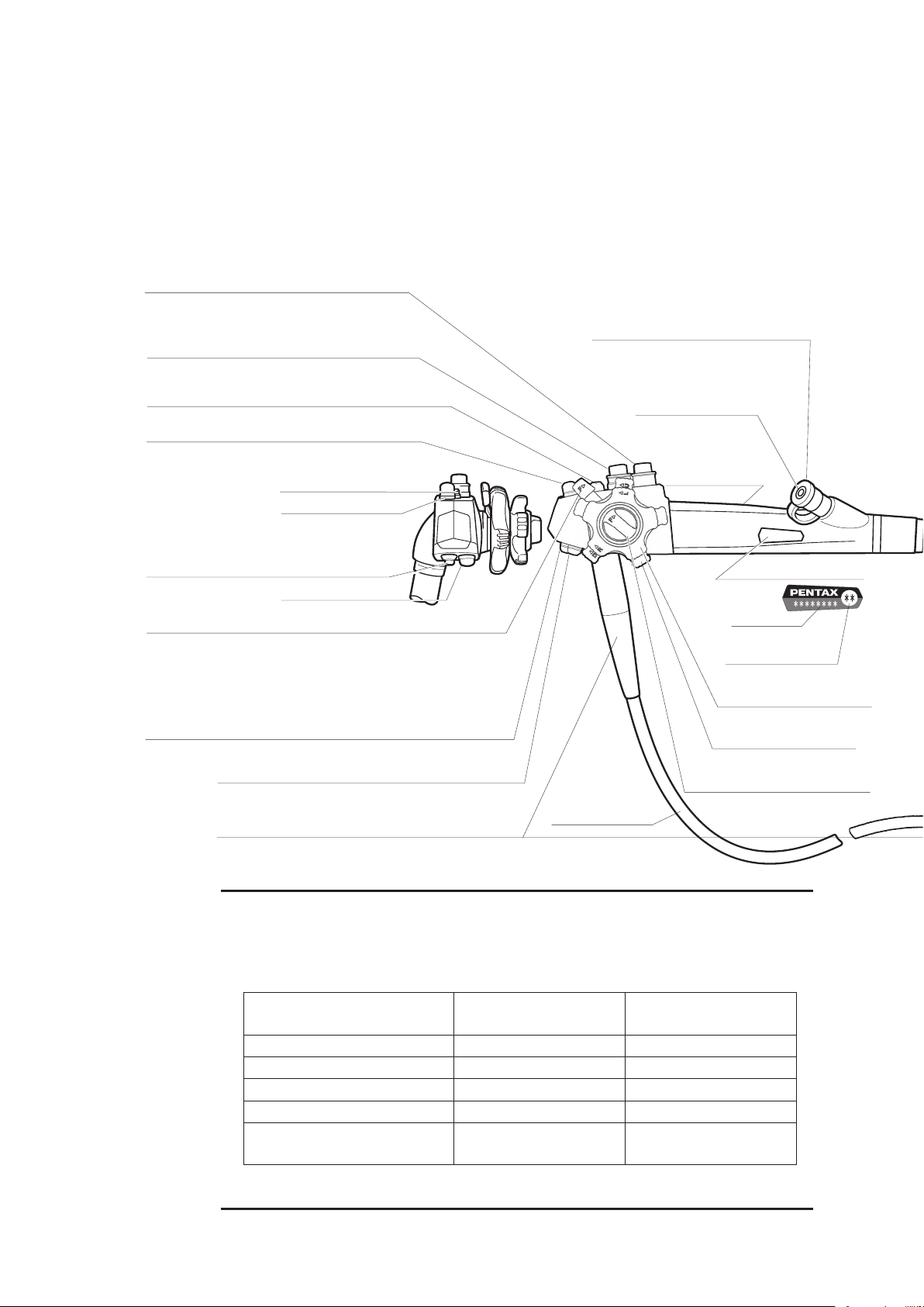
Push to freeze an image.
Push to activate the hardcopy system.
MODEL DESIGNATION
SUCTION CONTROL VALVE (OF-B120)
Depress to remove fluids or air through
the instrument channel.
AIR/WATER FEEDING VALVE (OF-B188)
Covering of hole in the top of the valve delivers
pressurized air. Covering of the hole and fully
depressing the valve delivers pressurized water.
UP/DOWN ANGULATION LOCK LEVER
When this lever is in the “F position, turned clockwise,
the bending section moves freely. When turned fully counterclockwise,
the bending section becomes progressively more stabilized.
Push to activate the Video for recording live procedures.
STRAIN RELIEF BOOT
INLET SEAL
Allows passage of accessories while
preventing escape of fluids and air.
CONTROL BODY
INSTRUMENT
CHANNEL INLET
For introduction of
biopsy forceps
and other accessories.
RIGHT/LEFT ANGULATION
CONTROL KNOB
UP/DOWN ANGULATION
CONTROL KNOB
RIGHT/LEFT ANGULATION LOCK KNOB
Functions similar to Up/Down lock
UMBILICAL CORD
PVE CONNECTOR
Can be rotated
within a 180˚
range.
AIR/WATER PORT
To connect feeding tube from water
bottle assembly.
REMOTE BUTTON 1
REMOTE BUTTON 4
MAGNIFICATION CONTROL LEVER (
EG-2990i
)
See detail Information on section 2-2.7) on page 22.
Allows connection of special irrigation tube
(OF-B113) for pressurized source of a spray
directed at the endoscopically visualized surface.
WATER JET PORT (Endoscopes with water jet system)
STRAIN RELIEF BOOT
To connect the OL-Z3 cable
From the a compatible
PENTAX video processor.
(Not available in EG-1690K)
FEEDBACK TERMINAL
REMOTE BUTTON 2
REMOTE BUTTON 3
REMOTE BUTTON 3
REMOTE BUTTON 1
REMOTE BUTTON 2
REMOTE BUTTON 4
MAGNIFICATION CONTROL LEVER (EG-2990i)
Model Name
Minimum Instrument
Channel Width
1. NOMENCLATURE AND FUNCTION
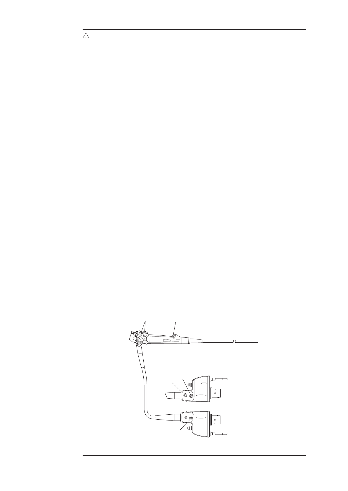
1-1. Video Endoscope
•EG-2990i, EG-2790i, EG-1690K, EG-2490K, EG-2790K, EG-2990K, EG-3490K, EG-3890TK
NOTE:
Function of each remote button depends upon the video processor. The
function can be changed. For more details, refer to the instructions for use
supplied with the video processor.
Endoscope Model
*Remote Button 1 Freeze Freeze
*Remote Button 2 Copy Copy
*Remote Button 3 Video Video
*Remote Button 4 - Enhance
**Magnication Control
Lever
*Setting at factory
**Not applicable to PENTAX Video Processor, model EPK-i5020
EG-2990i
EG-2790i/1690K/2490K/2790K
EG-2990K/3490K/EG-3890TK
Magnication(electronic) -
– 1 –
Page 7
LIGHT GUIDE PLUG
Transmits light from
light source to distal
end of endoscope.
SUCTION NIPPLE
For attachment to
external suction
source.
PVE CONNECTOR
Can be rotated
within a 180˚
range.
AIR/WATER PORT
To connect feeding tube from water
bottle assembly.
BENDING SECTION
VENTILATION CAP OF-C5
Provides venting of endoscope interior to equalize
internal and external pressures. This cap must be
removed before immersion.
VENTING CONNECTOR
Accepts “RED” Ventilation cap.
Also accepts Leakage Tester.
PVE SOAKING CAP
OE-C9
ELECTRICAL CONTACTS
INSERTION PORTION
(APPLIED PART)
RED
This cap must be securely attached before
immersion. Align the black arrow on the
soaking cap with the green dot at the base
of the silver collar surrounding the
electrical contacts on the PENTAX PVE
connector. Press the cap down onto the
metal collar and turn clockwise to secure.
Allows connection of special irrigation tube
(OF-B113) for pressurized source of a spray
directed at the endoscopically visualized surface.
WATER JET PORT (Endoscopes with water jet system)
STRAIN RELIEF BOOT
To connect the OL-Z3 cable
From the a compatible
PENTAX video processor.
(Not available in EG-1690K)
FEEDBACK TERMINAL
INSERTION TUBE
DISTAL END
CAUTION:
To avoid damaging the
endoscope, do NOT
twist, rotate or bend
excessively any of the
strain relief boot.
CAUTION:
Ensure that the soaking cap has been securely
attached (by properly rotating it) to prevent the cap
from coming off during reprocessing. Failure to
securely attach the soaking cap can result in endoscope damage.
CAUTION:
Immediately after use, the metal light guide plug and
the electrical contacts/pins of the endoscope may be
HOT. To avoid burns, do not touch these areas
immediately after use. For safer handling after a
procedure, grasp the PVE connector housing.
EG-3890TK ONLY
INLET SEAL
Allows passage of accessories while
preventing escape of fluids and air.
“B” identifies a small channel
“A” identifies a large channel
SUCTION CHANNEL SELECTOR OF-B161
Alignment of the indicator to the prescribed positions
allows the user the choice of suction capability through
either channel (2.8mm or 3.8mm) or simultaneous
suction through both channels
– 2 –
Page 8

UP/DOWN ANGULATION
CONTROL KNOB
RIGHT/LEFT ANGULATION
CONTROL KNOB
INSTRUMENT
CHANNEL INLET
For introduction of
biopsy forceps
and other accessories.
AIR/WATER FEEDING VALVE (OF-B188)
•EG27-i10/EG29-i10
Covering of hole in the top of the valve delivers
pressurized air. Covering of the hole and fully
depressing the valve delivers pressurized water.
SUCTION CONTROL VALVE (OF-B120)
REMOTE BUTTON 1
Push to freeze an image.
REMOTE BUTTON 2
Push to activate the hardcopy system that
was selected between “FILE” and “HARD COPY”.
UP/DOWN ANGULATION LOCK LEVER
When this lever is in the “F position, turned clockwise,
the bending section moves freely. When turned fully counterclockwise,
the bending section becomes progressively more stabilized.
Depress to remove fluids or air through
the instrument channel
CONTROL BODY
REMOTE BUTTON 4
Enhance
REMOTE BUTTON 3
Push to activate the VCR for recording live procedures.
RIGHT/LEFT ANGULATION LOCK KNOB
Functions similar to Up/Down lock
STRAIN RELIEF BOOT
UMBILICAL CORD
Minimum Instrument
Channel Width
Model Name
MODEL DESIGNATION
NOTE:
Function of each remote button depends upon the video processor. The function
can be changed. For more details, refer to the instructions for use supplied with
the video processor.
Endoscope Model
*Remote Button 1 Freeze
*Remote Button 2 Copy
*Remote Button 3 Video
*Remote Button 4 Enhance
*Setting at factory
– 3 –
EG27-i10
EG29-i10
Page 9

INSTRUMENT
CHANNEL INLET
For introduction of
biopsy forceps
and other accessories.
STRAIN RELIEF BOOT
INLET SEAL
Allows passage of accessories while
preventing escape of fluids and air.
DISTAL END
CAUTION:
To avoid damaging the
endoscope, do NOT twist, rotate
or bend excessively any of the
strain relief boot.
UP/DOWN ANGULATION
CONTROL KNOB
RIGHT/LEFT ANGULATION
CONTROL KNOB
PVE CONNECTOR
Can be rotated
within a 180˚
range.
INSERTION TUBE
INSERTION PORTION (APPLIED PA RT)
WATER JET PORT
(Endoscopes with water jet system)
Allows connection of special irrigation tube
(OF-B113) for pressurized source of a spray
directed at the endoscopically visualized surface.
AIR/WATER PORT
To connect feeding tube from water
bottle assembly.
BENDING SECTION
VENTING CONNECTOR
Accepts “RED” Ventilation Cap.
Also accepts Leakage Tester.
VENTILATION CAP OF-C5
RED
Provides venting of endoscope interior to equalize
internal and external pressures. This cap must be
removed before immersion.
ELECTRICAL CONTACTS
PVE SOAKING CAP OE-C9
This cap must be securely attached before
immersion. Align the black arrow on the
soaking cap with the base of the silver collar
surrounding the electrical contacts on the
PENAX PVE connector. Press the cap
down onto the metal collar and turn
clockwise to secure.
FEEDBACK TERMINAL
To connect the OL-Z3 cable
from the PENTAX video
processor
SUCTION NIPPLE
For attachment to
external suction
source.
LIGHT GUIDE PLUG
Transmits light from
light source to distal
end of endoscope.
CAUTION:
Ensure that the PVE soaking cap has been securely
attached (by properly rotating it) to prevent the
cap from coming off during reprocessing. Failure to
securely attach the cap can result in endoscope
damage.
CAUTION:
Immediately after use, the metal light guide plug
and the electrical contacts/pins of the endoscope
may be HOT. To avoid burns, do not touch these
areas immediately after use. For safer handling after
a procedure, grasp the PVE connector housing.
– 4 –
Page 10

1-2. Accessories
(2)
(3)
1) Biopsy Forceps
Figure 1.1
Biopsy Forceps/Endoscope compatibility
(1)
(4)
Biopsy Forceps Endoscope
EG-2990i/ EG-2790i/ EG-2790K
KW2415R
EG-2990K/ EG-3490K/ EG-3890TK/
EG27-i10/ EG29-i10
KW1815S EG-1690K/ EG-2490K
(1) Flexible Shaft
(2) Grip
(3) Handle (pink handle
denes autoclavable
forceps)
(4) Cups/Jaws
CAUTION:
• Because of the effect that accessories used through the instrument
• Maximum outer diameter of an endoscopic accessory instrument
NOTE:
• Depending upon country and/or local PENTAX service facility, each
• For patient contact endoscopic accessories, follow the specific and
• To confirm the exact condition of any new accessory device, check
channel of the endoscope can have on the performance of the
endoscope itself, it is strongly recommended that PENTAX accessories
be used with PENTAX endoscopes. If a unique or highly specialized
accessory is available from another source and its manufacturer claims
compatibility with PENTAX instruments, the accessory manufacturer
should be consulted to confirm compatibility with PENTAX endoscope
before use.
must be at least 0.2 mm less than the specied instrument channel
diameter in PENTAX endoscopes. Working length of an endoscopic
accessory instrument may be approximately 30 cm longer than the
endoscope working length.
PENTAX endoscopic accessory may be an optional accessory.
detailed instructions on use, care and maintenance supplied with each
product.
the labeling/packaging accompanying the product. Each label/package
should clearly identify the contents as either sterile or non-sterile.
– 5 –
Page 11
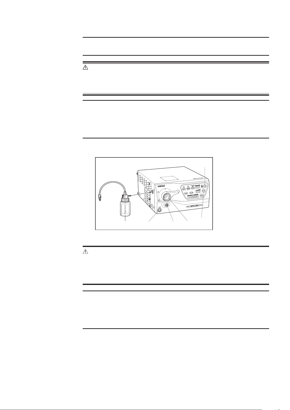
1-3. Video Processor
(6)
(1)
(5)
(4)
NOTE:
Read the instructions for use supplied with the video processor.
WARNING:
Do not install, operate or store electro-medical equipment in a dusty
environment. Accumulation of dust within these units may cause
malfunction, smoke, or ignition.
NOTE:
Be sure to use compatible bottle and water bottle cap. If incompatible
bottle and a water bottle cap are used together, it could cause the air to
escape resulting in insufcient pressure and ow of air and water during
the endoscopic procedure.
1) PENTAX Video Processor
(1) Lamp Switch
(2) Pump Switch
(3) Endoscope Electrical
Connector
(4) Light Guide
Receptacle
(5) Power Switch
(6) Water Bottle Assembly
(2)
(3)
Figure 1.2
CAUTION:
Replace the lamp before the lamp life expires. Prior to use, check the lamp
life indicator. Excessive use of the lamp beyond the lamp life could cause
the lamp to explode resulting in damage to the video processor. Refer to
the video processor's instructions for use regarding the lamp life.
NOTE:
Software update may be required depending on the software version of
the PENTAX video processor. If the software is not updated, the image will
not be displayed. If the images are not displayed correctly, please contact
your local PENTAX service facility.
– 6 –
Page 12

2. PREPARATION AND INSPECTION FOR USE
Prior to use, the endoscope, video processor and endoscopic accessory instruments must be
carefully inspected for cleanliness and proper function to determine that they are appropriate
for patient use.
NOTE:
PENTAX video endoscope contained in this instructions for use is only
compatible with PENTAX video processors.
CAUTION:
To avoid discontinuation of endoscopic procedure, have an extra (spare)
instrument available as a standby device. Should any unforeseen event or
circumstance render the original instrument inoperable and/or unsafe for
patient.
2-1. Inspection of the Video Processor
NOTE:
For details of operations such as starting and stopping, please refer to the
PENTAX Video Processor Instructions for Use.
WARNING:
To avoid the risk of an electric shock, check that the video processor is
properly grounded, or that it is connected to an appropriate isolation
transformer (PENTAX SAT-1300 or other medical purpose isolation
transformers). Also, be sure to use a video processor specied by PENTAX.
1) Attach water bottle assembly, 2/3 filled with sterile water to the appropriate
location on the left side of the video processor.
WARNING:
The addition of defoaming agents to the water supply is NOT
recommended. Due to their nature, these silicone based agents cling
tenaciously to surfaces. Unless they are rinsed very thoroughly, a “barrier”
could be created which could reduce the effectiveness of the disinfection/
sterilization process. Additionally, repeated use of such defoamers
could eventually lead to residual silicone build up resulting in equipment
malfunction such as clogged air and/or water channels.
2) Set the drain lever on the water bottle assembly to the upright position labeled
A/W (air/water).
3) Plug the video processor into a properly grounded receptacle with the power
switch in the OFF position.
– 7 –
Page 13

4) Make sure that the PENTAX PVE connector is aligned with the Endoscope
(1)
Electrical Connector and Light Guide Receptacle on the front panel of the video
processor.
5) Connect the endoscope to the Endoscope Electrical Connector and Light Guide
Receptacle on the video processor as illustrated.
(1) Air/Water Feeding
Tube
Figure 2.1
6) Rotate the locking lever clockwise after insertion.
CAUTION:
After connecting the endoscope to the PENTAX video processor, always
make sure that the endoscope is firmly secured to the endoscope
receptacle by turning the locking lever to the “lock” position.
7) Connect the air/water feeding tube from the water bottle assembly to the air/water
port on the side of the PVE connector.
8) Turn the video processor and air pump to the “ON” position and check for proper
functioning.
9) Press the lamp switch of the video processor to turn ON the lamp.
CAUTION:
Do not look directly at the light emitted from the endoscope distal tip or
the video processor unit. The intense light might hurt your eyes. Turn off
the lamp when looking directly at the endoscope distal tip.
10) Prior to each procedure, check the endoscope image quality displayed on the
monitor. Confirm that the image quality, color, automatic brightness (iris)
functions are acceptable as per the instructions provided with the PENTAX video
processor.
– 8 –
Page 14

2-2. Inspection of Endoscope
WARNING:
Disassembling or modifying a PENTAX endoscope may impair its original
functionality and possibly result in a serious injury. Never disassemble or
modify the endoscope.
WARNING:
If the endoscope is intended to be clinically used after testing of individual
endoscope functions (suction, air/water delivery, water jet, etc.) without
further reprocessing, the following precaution should be exercised.
Use sterile water during individual endoscope function tests to avoid
recontamination of the previously reprocessed instrument by waterborne
microorganisms. Sterile water should be used during endoscopic
examination also. Tap water, especially that which may be left idle and
uncovered for a prolonged period of time, should not be used during any
inspection/testing of the endoscope.
Before proceeding with inspection of individual functions, PENTAX endoscopes should be
tested for the integrity of their water-tight design (example: tear in the instrument channel).
CAUTION:
PENTAX endoscopes should be tested for the integrity of their watertight design using PENTAX leakage tester. If the endoscope is used in a
condition where the integrity of its water-tight design is compromised, it
could result in endoscope damage due to permeated water.
CAUTION:
Various types of endoscope leakage testers exist including manual,
electro-mechanical and “automated” versions, some of which are stand
alone units and others which may be integrated into Automated Endoscope
Reprocessors (AERs)/Washer-Disinfectors (WDs). It must be recognized
that PENTAX does not evaluate non-PENTAX leakage tester systems to
satisfy their specic products claims, for their effectiveness to accurately
detect leaks and/or for their compatibility with PENTAX endoscopes.
Insufficient pressures may adversely affect the endoscope, especially
if pressurization occurs during automated reprocessing at elevated
temperatures. PENTAX accepts no responsibility for use of non-PENTAX
leakage testers. Users should check with the leakage tester manufacturer
and confirm their specific product claims, including compatibility with
PENTAX endoscopes at various temperatures and their ability to detect
leaks with/without fluid immersion and with/without flexing of the
endoscope’s distal bending section.
– 9 –
Page 15

1) Inspection of the Insertion Portion
(3) (4)
a) Check the entire surface of the insertion tube for abnormal conditions such as
sharp edges, dents, crush marks, wrinkles, bumps, buckles, excessive bending,
protrusions, bite marks, peeling of outer sheath, cuts/holes or other irregularities.
Any crush or indentation of the flexible shaft of the endoscopes can cause
damage to the internal mechanisms of the endoscopes.
b) Similarly, check the condition of the umbilical cord for outward signs of damage
such as buckling, crush marks, etc.
WARNING:
To avoid serious damage to the patient or possibility of malfunction during
a procedure, do not use any endoscope if you nd any abnormalities or
outward signs of damage.
c) These areas [A], [B] should be checked for ANY abnormalities or irregularities.
If anything unusual is found including but not limited to rough textured surfaces,
cracks, brittleness, sharp-edges, holes, peeling, tackiness, etc., the endoscope
should NOT BE USED. During this inspection process check the surface/
condition of the adhesive by applying slight pressure with one's gloved ngers
and by slightly wiping this area with dry gauze.
Make sure the adhesive band is not peeling, nor does it have roughened texture
or any sharp-edges.
(1) Bending Section
(2) Close-Up View
(3) [A] Black Adhesive
(2)
(1)
Figure 2.2
Band
(4) [B] Black Adhesive
Band
d) Make sure that the entire endoscope is clean and has been subjected to either a
high-level disinfection or sterilization process before each patient use.
WARNING:
From the standpoint of infection control, all instruments must be
reprocessed prior to first time use, after any repairs/service and before
every patient use.
CAUTION:
In order to obtain crisp endoscopic images, when utilizing chemo-thermal
processes for reprocessing PENTAX endoscopes, the instruments should
be allowed to return to room temperature prior to use and/or further
handling.
– 10 –
Page 16

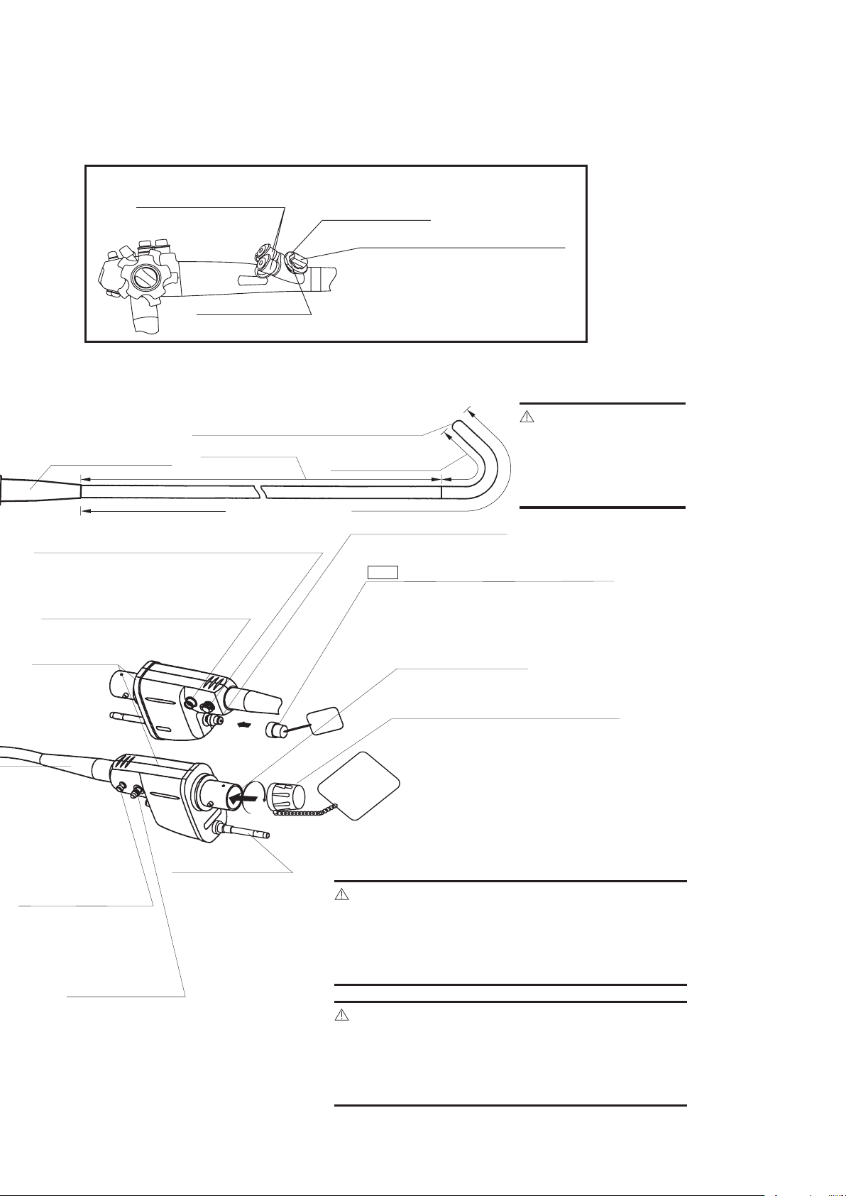
2) Inspection of insertion tube exibility
a) Form an arch with the Insertion Tube as shown in the gure below.
Approx.
30cm
Approx. 20cm
Figure 2.3
b) Gently raise/lower the left/right hands alternately and conrm equal exibility
for the length of the loop. Do NOT use the endoscope if there are any:
• extraordinarily rigid portion which do not bend as easily as the rest of the arch.
• extraordinarily exible portions which bend much more than the rest of the arch.
Figure 2.4
Figure 2.5
c) Repeat steps a) and b) above until the inspection of the entire insertion tube is
complete. If the endoscope fails the inspection above;
• Do NOT use the endoscope and
• Contact your local PENTAX service facility.
– 11 –
Page 17

CAUTION:
When performing this inspection, ensure that other components of the
endoscope (distal end, control body, etc.) are not damaged by impact to
surface or objects in the area.
Do NOT exercise the bending section of the endoscope as part of this
inspection. Maintain the distal end in a straight orientation. Hold the
insertion tube at the junction of the insertion tube and bending section.
Do not close your hand around the bending section. It could cause the
bending section to be damaged.
CAUTION:
The distal end of the endoscope as well as the electrical contacts/pins on
the PVE connector must be protected against damage from impact. Never
apply excess force such as twisting, or severe bending to the flexible
portion of the endoscope. These actions could result in endoscope damage
or membrane/tissue damage to the patient. Therefore, do not use the
endoscope if there is any sign of abnormalities in the distal end of the
endoscope.
CAUTION:
During pre-use inspection, ensure that the distal objective lens and the
illumination (LCB) cover glass are clean. If not, crisp images can NOT be
displayed.
NOTE:
As indicated elsewhere in PENTAX product labeling, endoscopes particularly
the quality of the endoscope image should be checked prior to patient use.
CAUTION:
When transporting the endoscope, do NOT grasp or carry it only by its
umbilical cord or insertion tube, and take care to protect the distal tip of
the insertion portion from damage. Loosely coil both the umbilical cord
and insertion tube so that the endoscope can be carried by grasping both
the control body and distal portion of the insertion portion in one hand and
the PVE connector in the other hand. Failure to do so could result in severe
impact damage that will require repair by PENTAX service personnel.
Figure 2.6
– 12 –
Page 18
CAUTION:
Flexible endoscopes and other sophisticated medical devices are
constructed of special materials, unique parts and intricate components
with strict dimensional tolerances. Specialized assembly techniques
and application of specific sealants and/or adhesives are required to
ensure the watertight integrity and maintain the functionality of these
devices. It is therefore imperative that endoscopes be routinely checked
to ensure that parts used in their construction are not loose, missing or
compromised that could otherwise negatively affect the functionality of
these devices. Compromised or loose components could result in device
failure, endoscope damage (via fluid invasion) and/or in incomplete
decontamination of used instruments.
PENTAX recommends that prior to use endoscopes should be carefully
inspected for their integrity and checked for any “looseness” in the mating
or joining of components including the following parts/areas:
• the instrument channel inlet (biopsy inlet port) (1)
• the suction nipple (2)
• the air/water port (3)
• the water jet connector (4)
• any valve cylinder (5)
• basically, any inlet or outlet port associated with an internal channel, an
indirect patient contact portion of the endoscope
• strain relief boot along insertion tube and umbilical cord (rotate
clockwise only to tighten)
One method to check for looseness is to lightly grip the exposed part,
and while grasping the component carefully attempt to move it in
various directions. Use of a lint free gauze while grasping metal parts is
recommended as a protection for one’s ngers.
If any part/component remains loose (after attempting to tighten)
and/or if there is any indication or suspicion of an abnormality or
outward signs of damage, do NOT use the endoscope. Contact your
local PENTAX service facility.
Figure 2.7
(5)
U
L
F
F
R
D
(4)
(1)
(3)
(2)
– 13 –
Page 19

CAUTION:
To avoid damaging the endoscopes, do NOT twist, rotate or bend
excessively any of the strain relief boots (1), (2) during inspection, clinical
use, reprocessing or any handling activity. Be particularly cautious for the
insertion tube strain relief boot (1). When wiping the insertion tube and
the umbilical cord, use a slow back and forth motion to wipe them along
the tube/cable. Never apply excessive force or torque on these strain relief
boots or slim tubes/cables. During ANY handling of the instrument avoid
excess force, twisting, rotation and/or bending of the actual insertion tubes
and umbilical cord to prevent inadvertent damage (crush, compression,
deformity, etc.) to these parts as well as to internal components contained
within the endoscope.
F
F
U
L
F
R
D
U
L
F
R
D
Do NOT Twist or Rotate Do NOT Bending
U
L
F
F
R
D
(1)
(2)
Figure 2.8
3) Inspection of Angulation Controls and Locks
a) Slowly manipulate the Up/Down and the Right/Left control knobs to see that
they function smoothly. Be certain that a full and appropriate range of angulation
is possible.
b) Check that the observed image turns in the intended direction when the control
knob is operated to move the angulation up/down and left/right.
– 14 –
Page 20

c) Engage fully the angulation locks to be certain that the position of the angulated
(2)
(1)
tip can be stabilized.
(1) Right-Left
(2) Up-Down
Figure 2.9
F
U
L
F
R
D
(1)
WARNING:
Prior to use ensure that the angulation controls can rotate smoothly,
that there is no grinding or excess friction within the angulation system
and that the bending section bends freely and smoothly. NEVER APPLY
EXCESSIVE FORCE TO THE ANGULATION CONTROLS!
ANY lack of smooth operation of the angulation controls may be an
early indication of internal damage to and/or part(s) failure within
the endoscope’s angulation system. To avoid the possibility of further
endoscope damage or the potential for malfunction of the angulation
system, do NOT use the endoscope if the angulation mechanism does not
operate properly. Use of endoscope with suspect angulation mechanism
could lead to angulated distal tip to not being able to be released and end
up damaging patient tissue/membrane or perforation.
CAUTION:
When an endoscope exhibits excessive “knob play” or if angulation is lost
in any direction, do NOT use the instrument.
Excessive “knob play” can be dened as rotating of the angulation control
knob(s) in any one direction for more than 30 degrees without any
corresponding distal tip angulation. The examples above are indications
that service is required to avoid more serious problems with the angulation
control system.
4) Inspection of Air/Water Feeding System
a) Prior to use, the air/water feeding valve (OF-B188) should be inspected. Remove
the air/water valve from the control body and ensure that O-rings in good
condition are properly attached.
(1) OF-B188
(2)
(3)
(2) Cap
(3) O-Ring
(4) Check Valve
(4)
Figure 2.10
– 15 –
Page 21

WARNING:
If air bubbles discharge continuously from the distal end of the endoscope
during inspection, it is possible that the O-ring may be damaged, installed
incorrectly, or the air/water feeding valve may be damaged or installed
incorrectly.
If the device is used in this condition, it could cause infection by cross
contamination to the patient as result of reflux or spit-back of patient
fluids from the valve or damage the patient’s body cavity. Also, the air
could be delivered to the patient's body excessively as well as continuously
and expose the patient to pain and suffering and/or cause damage as
result of gas embolism, etc.
Therefore, if the aforementioned characteristic was observed, make sure
to replace the O-ring or the air/water feeding valve with fully reprocessed
new ones which have already been subjected to a high-level disinfection
or sterilization procedure (O-ring set, model OF-B192, and the air/water
feeding valve, model OF-B188 can be used) and perform the inspection
again.
Since the check-valve can NOT be replaced by the end user, replace the
entire A/W valve with a new one if the check valve is damaged/missing.
b) Install the valve into the A/W cylinder by gently pushing the valve into the
cylinder. Never apply excessive force to push the valve into the A/W cylinder.
c) Connect the endoscope to the video processor. Turn air pump “ON” to desired
pressure setting. Place the endoscope distal tip into sterile water and conrm that
no air bubbles exit the distal air nozzle.
d) To inspect air delivery, cover the hole at the top of the air/water valve and
conrm that air ows freely from the air/water nozzle at the endoscope distal tip.
e) By depressing the air/water feeding valve, the water delivery system is activated.
Water should ow in a steady stream from the air/water nozzle at the distal tip
of the endoscope. (This may take several seconds on the initial attempt.) USE
STERILE WATER ONLY.
Action
Result
Air
–
Feeding
Water
Feeding
– 16 –
Page 22

f) Release the air/water feeding valve to determine if the valve freely returns to its
OFF (neutral) position and delivery of water (and air) ceases.
CAUTION:
Before use, make sure that the air/water feeding valve is not clogged or
does not have any other problem that could cause the uninterrupted ow
of air/water. If the endoscope is used in such condition, it will hinder its
capability to clear the debris off the objective lens and the endoscopic
examination might be interrupted.
NOTE:
(EG-1690K)
The EG-1690K have a single, common internal channel, and a single
shared nozzle for air/water delivery. Since these functions occur within
a single channel, the following may be experienced when alternating
between these functions:
• A slight delay in air delivery with subsequent residual water ow
may occur immediately after switching from water to air activation.
This flow of fluid is due to the purging of residual fluid from the
common internal channel.
• A slight delay in water delivery may occur if activated
immediately after air delivery due to lling of the empty common
internal channel occupied by air.
g) If air and/or water do not ow properly, the following steps should be followed.
[1] Disconnect the endoscope from the video processor.
[2] Remove the suction control valve and the air/water feeding valve.
[3] Using a cotton tipped applicator and alcohol, clean the valve recess
(receptacle) in the control body thoroughly to remove any debris. Do NOT
attempt to insert the applicator into the small openings within the valve
receptacle as the cotton or applicator could become lodged within these
openings and cause channel blockage.
[4] • Following the companion Instructions for Use (reprocessing) for chemical
cleaning of the air and water channel with detergent, flush detergent
through both the air and water channels.
Rinse the air and water channel(s) with sterile water.
Then flush the air several times to force any residual solution out of the
channel.
• If the cleaning adapter is being attached, remove the adapters and install
the air/water feeding valve.
(Alternate) By leaving the air/water feeding valve in the cylinder instead of
the OF-B153 adapter, one may direct pressured fluid (or air) independently
to either channel to expel debris from and/or more forcefully flush solution
into either the air or water channel. This should not be attempted on a
completely clogged/blocked air or water channel/nozzle.
[5] Test for normal delivery of air and water. It may be necessary to repeat the
above procedure if normal air and water delivery is still not available.
– 17 –
Page 23

CAUTION:
(2)
(1)
Do NOT apply excessive force or use a sharp object in an attempt to
unblock a clogged channel as the endoscope channel could become
damaged. Whenever channel damage is suspected, the endoscope should
be leak tested.
If repeated attempts to flush the air/water system are unsuccessful, do
not attempt to use the endoscope on a patient.
Contact the PENTAX service facility.
h) If the air/water feeding valve does not function properly, does not move smoothly
or feels “sticky”, remove the valve and apply a very small amount of silicone oil
lubricant (OF-Z11) onto all the O-rings. Do NOT use excess oil, avoid “blobs”,
large drops and/or squirts of oil directly onto the metal valve stems - instead,
simply place a small droplet of oil on one’s sterile gloved forenger and gently
swirl between thumb and forenger. Next place the valve with O-ring in-between
thumb and nger and gently rotate the valve so that the oil is evenly applied to
the outer edges of each O-ring. Make sure the oil is applied to all O-rings and
wipe off all excess.
Do NOT apply excess oil. Doing so can allow for inadvertent migration of the
oil inside channels or other areas not intended to be lubricated.
NOTE:
Prior to clinical use, it is important that the entire air channel system be
dry. Failure to thoroughly dry the air system could result in an unclear or
blurry image caused by very fine droplets of moisture being swept over
and/or onto the objective lens at the distal end of the endoscope.
5) Inspection of Water Jet (Endoscope with water jet system)
a) Prior to use, the water jet check valve adapter (OE-C12) should be inspected.
Open the water jet connector cap (OF-B118). Turn the water jet adapter
counterclockwise and remove it from its cylinder. Make sure that the black
check-valve (OE-C14) is properly attached to the bottom of the water jet check
valve adapter.
If the check-valve is missing or not attached properly, correctly reposition the
check-valve by turning it several times on the water jet adapter unit.
For proper positioning, there should be no clearance (gap) between the check-
valve and the water jet check valve adapter stem.
(1) OE-C12
(2) OE-C14
Figure 2.11
– 18 –
Page 24

WARNING:
The check-valve OE-C14 is a reusable component and it as well as the OEC12 check valve adapter, water jet cylinder, irrigation tube and water jet
channel should be reprocessed after each use.
Make sure that the check-valve OE-C14 is securely attached to the check
valve adapter OE-C12.
A worn or damaged check valve should be replaced with a new one which
has already been subjected to a high level disinfection or sterilization
procedure (Check valve set, model OE-C15 which contains 10 pieces of
OE-C14 is optionally available).
For repeated use, always ensure that the valve has already been
reprocessed. A damaged, worn or missing check-valve could create a risk
of cross-contamination to the end user due to the potential for reux (spitback) of patient uids through an unsealed path if the check-valve is not
attached properly.
b) Attach the water jet check valve adapter (OE-C12) and water jet connector cap
(OF-B118) opened and then irrigation tube (OF-B113) to the water jet port on
the (PVE) connector.
c) Attach a syringe lled with sterile water to this tube and ush water through the
tube. Water should ow in a steady and forceful stream from the water jet nozzle
at the distal end of the endoscope (this may take several seconds on the initial
attempt).
(1)
(2)
(3)
Figure 2.12
(1) Water Jet Connector
Cap (OF-B118)
(2) Irrigation Tube
(OF-B113)
(3) Water Jet Check Valve
Adapter
(OE-C12)
d) Use only sterile water in the water jet system.
e) If water does not ow properly, the following steps should be followed:
[1] Attach a syringe lled with a compatible cleaning detergent solution to the
irrigation tube.
[2] Flush solution through the tube and nozzle. Soaking of the water jet channel
with detergent solution should help dissolve and dislodge whatever is
restricting the normal forceful stream from the water jet nozzle.
[3] Remove the syringe containing detergent solution and attach a syringe with
air. Purge the channels with air and then rinse the air and water channel(s)
with sterile water. Then, flush air through the irrigation tube and nozzle
several times to remove any residual solution from the tubing and nozzle.
– 19 –
Page 25

CAUTION:
It may be necessary to repeat the steps above several times to obtain
proper water jet function.
If water still does not ow properly after several attempts, contact your
local PENTAX service facility.
Do NOT apply excessive force or use a sharp object in an attempt to
unblock a clogged channel as it could result in endoscope damage.
f) In place of manual flushing via syringe, specially designed irrigator pumps
intended for endoscopic irrigation may be used via the PENTAX water jet
system. PENTAX check-valve mechanisms should always be connected and
positioned within the water jet channel pathway. Always use the lowest irrigator
pump setting as the procedure requires and increase water ow rates as patient
conditions allow.
WARNING:
Although the water jet system may not be clinically used during each
procedure, because the water jet channel of the endoscope enters the
body cavity, it can be contaminated the same way as the insertion
portion of the endoscope. Therefore, it still MUST be properly cleaned and
subjected to the same disinfection/sterilization processes as other internal
channels of the endoscope.
NOTE:
The water jet system featured in PENTAX endoscopes should not be
confused with “auxiliary” or manual water feed systems whose function
is simply to clean the distal objective lens. A true water jet allows the
endoscopist to direct a forceful stream of water to clear blood, debris, etc.
from a particular area of interest to improve visualization.
(1) Water Jet water shoots straight
out to area of interest
(1)
(2)
Figure 2.13
(2) Auxiliary Water System water
is directed across endoscope
tip to clean lens
– 20 –
Page 26

6) Inspection of Suction Channel Selector (EG-3890TK ONLY)
(2)
(1)
a) Check the condition of the Suction Channel Selector (OF-B161). The selector
knob should move smoothly when rotated and click into position at the
prescribed indicators. The Suction Channel Selector allows the user the choice of
suction capability through either channel, or simultaneous suction through both
channels.
NOTE:
The suction channel selector knob can be rotated either clockwise or
counterclockwise.
WARNING:
NEVER use the Suction Channel Selector (OF-B161) with any outward signs
of damage or any abnormal conditions. Using a compromised selector or
failure to attach the selector appropriately to the suction selector cylinder
could result in decreased suction capability, air/fluid leakage and/or the
potential for cross contamination due to the possible reux or spit-back of
patient uids.
HANDLING OPERATION
Simultaneous
suction through
both channels.
1) Suction Channel
(
Selector
Suction through
the small channel
only.
“B”
(1)
“A”
“B”
Align the suction channel selector
knob to the combined “A B”
indicator and depress the suction
valve to start/stop activation of
suction.
Align the suction channel selector
knob to the single “B” indicator
and depress the suction valve to
start/stop activation of suction.
Suction through
the large channel
only.
Align the suction channel selector
knob to the single “A” indicator
and depress the suction valve to
start/stop activation of suction.
“A”
b) Should the suction channel selector not rotate smoothly, it might require further
cleaning.
(1) Suction Channel
Selector
(2) Suction Cylinder
Figure 2.14
– 21 –
Page 27

[1] Remove the entire suction channel selector mechanism from the endoscope.
(5)(4)
[2] Scrub all internal and external surfaces of the suction channel selector using
the smaller side of the cleaning brush (CS-C9S).
(1) Suction Channel
(1)
(2)
Figure 2.15
Selector
(2) CS-C9S
[3] Using the large bristle of the specially designed cleaning brush, CS-C9S,
insert the brush into the opening of the suction channel selector cylinder.
Thoroughly clean the surface areas.
[4] Next, thoroughly clean the suction channel selector and rinse well
7) Inspection of Remote Buttons and Magnication Control
a) Remote Buttons
Check to ensure that the function that you assigned to each remote button works
properly.
NOTE:
The function can be assigned to remote buttons #1, #2, #3, or #4.
For more details, refer to the instructions for use supplied with the video
processor.
b) Magnication Control
NOTE:
PENTAX Video Processor, model EPK-i5020 is not compatible.
(1) Endoscopes with the
(1) (2)
(3)
Magnication Control
Lever
(2) Endoscopes without the
Magnication Control
Lever
(3) Magnication Control
Lever
(4) Standard Image
(5) Magnied Image
Figure 2.16
– 22 –
Page 28

[1] Endoscopes with the Magnication Control Lever
Turn the magnication control lever clockwise to magnify the image up to
two times. Turn counterclockwise to return to the original size.
[2] Endoscopes without the Magnication Control Lever
Press the remote button which the magnification function is assigned to
magnify the image. Pressing the same remote button again will make the
image return to the original size.
NOTE:
As this magnication function is performed electronically, focus and depth
of eld do not change. Clarity is slightly reduced.
8) Inspection of Suction Mechanism
a) Prior to use, the suction control valve (OF-B120) should be inspected. For easier
identication, an orange colored indicator is placed on top of the OF-B120 valve
mechanism. Remove the valve from the control body and make sure that rubber
portions of the valve are not damaged or worn.
(1)
Figure 2.17
WARNING:
Make sure that the correct suction control valve (OF-B120) is being used.
A worn or damaged valve and/or O-ring should be replaced with a new
one. The entire valve mechanism should be subjected to a high-level
disinfection or sterilization procedure prior to use (O-ring set, model OFB127, is optionally available). Failure to do so could result in continuous
aspiration which in certain clinical situations can suction tissue into
the distal channel opening at the endoscope tip and/or create a loss of
insufated air via the suction system.
A compromised valve could also result in the potential for reux or spitback of patient uids that may present infection risks.
(1) OF-B120
b) Position the valve OF-B120 so that the small metal tab near the base on the valve
stem aligns with the notched suction valve cylinder, also color coded in orange.
Install the valve into the suction cylinder by gently pushing the valve into the
cylinder. Never apply excessive force to push the valve into the suction cylinder.
– 23 –
Page 29

Figure 2.18
(1)
(2)
(1)
(3)
Figure 2.19
(2)
(1) Suction Control Valve
1
2
(1)
OF-B120 (orange)
(1) Depress
F
U
L
F
F
R
D
(3)
(4)
(2) Suction Source Tube
(3) Suction Nipple
(4) Inlet Seal
(1) Correct
(2) Incorrect
OF-B120
Figure 2.20
OF-B120
(3) Metal
WARNING:
Make sure suction control valve OF-B120 is correctly attached (see gure
2.21).
Improperly installed valves may not function as originally intended. Such
valves may not return to their neutral (released) positions and/or they
may provide continuous suction.
Continuous aspiration can cause loss of air/uid, difculty in maintaining
proper insufation and/or inadvertent suctioning of tissue into the distal
instrument channel opening. Also it could possibly result in the potential
for reux or spitback of patient uids.
c) Connect suction tubing from an external suction source to the suction nipple
located on the PVE Connector at the end of the umbilical cord. Make sure that
the inlet seal is attached to the instrument channel inlet. Place the distal tip of the
endoscope in a basin of sterile water and depress the suction control valve. Water
should be rapidly aspirated into the suction system collection container.
– 24 –
Page 30

WARNING:
(3)
(2)
(1)
(1)
An inlet seal in good condition (that is not worn or damaged) must be
attached to the instrument channel inlet to prevent the loss of suction and
a risk of cross contamination to the end user due to the potential for reux
(spit-back) of patient uids. Worn seals will result in leakage and should be
replaced. To ensure maximum performance of these sealing mechanisms,
consider replacing the inlet seal with a fully reprocessed new one for each
procedure.
d) Release the suction control valve to determine if the valve freely returns to its
OFF position and the aspiration of water ceases.
e) If the suction control valve does not move smoothly or feels “sticky”, remove the
valve from the suction cylinder on the control body of the endoscope. Apply a
small amount of silicone oil lubricant (OF-Z11) onto rubber part and the O-ring.
Place a small droplet of oil (OF-Z11) on one’s sterile gloved forefinger and
gently swirl between thumb and forenger. Next place the valve with O-ring in-
between thumb and nger and gently rotate the valve so that the oil is evenly
applied to the outer edges of the O-ring.
Remove/wipe off excess lubricant with a soft gauze. Do not use excessive
silicone oil.
(1) OF-B120
(2) Rubber Part
(3) O-Ring
Figure 2.21
9) Inspection of Biopsy Forceps and Instrument Channel
a) Make sure there are no kinks in the exible shaft of the biopsy forceps.
b) The cups/jaws of the forceps must be free of any residual debris. Any debris
must be cleaned from the forceps before they are used. USE ONLY STERILE
FORCEPS.
c) The handle mechanism on the forceps should be operated to open and close the
cups/jaws. This mechanism should operate freely.
(1) Close
(2)
(2) Open
Figure 2.22
– 25 –
Page 31

d) Close and inspect the cups/jaws of the forceps to make sure the cups/jaws are
in proper alignment. If the forceps has a spike, the spike must be completely
straight and fully within the cups/jaws.
WARNING:
The use of any forceps or accessory that shows any sign of damage or
difficulty of operation must be avoided. Any malfunction of a forceps or
accessory during a patient procedure could result in serious injury to the
patient. Also, the use of damaged forceps or accessories may result in
serious and costly damage to the endoscope.
e) Any accessory should be slowly inserted through the instrument channel inlet
with the endoscope in a straight position.
There should be no resistance encountered. If resistance is encountered, do not
attempt to introduce the accessory further.
The instrument channel may be damaged and the endoscope should not be used.
Contact the PENTAX service facility.
WARNING:
From the standpoint of infection control, all patient contact accessories
must be thoroughly cleaned and subjected to an appropriate high-level
disinfection or sterilization process before being used for the rst time and
subsequently after each clinical use.
CAUTION:
The instrument, A/W and the water jet channel systems are made of
stainless steel, Noryl and uorine-contained polymers. When any uids are
used with this endoscope, please read carefully and follow all instructions
in the instructions for use supplied with the uids for use and pay special
attention to any reactions with the materials identied in the intended uid
path.
NOTE:
Endoscope instrument, A/W and the water jet channels are composed
of stainless steel, Noryl and fluorine contained polymers. PENTAX is not
aware of any reports of material incompatibility between these materials
and fluids that are commonly used during endoscopic procedures. As
relates to reprocessing, PENTAX publishes a list of compatible detergents
and disinfectants. In the event that the healthcare team intends to infuse
a less commonly or rarely used fluid through the instrument channel in
conjunction with a procedure, it is strongly advised that the manufacturer
of the fluid be consulted for material compatibility information with
stainless steel and polymers containing uorine. Also, please consult the
PENTAX list of compatible reprocessing agents for guidance regarding
compatible detergents and disinfectants.
NOTE:
Accessories should always be inspected and checked with the particular
endoscope prior to each procedure.
– 26 –
Page 32

CAUTION:
Do NOT clinically use the endoscope if any irregularity or abnormality
is suspected. If there is any doubt as to the suitability of use for any
endoscope component, replace it with a new fully reprocessed one. An
instrument irregularity may cause endoscope damage and/or compromise
patient or user safety.
CAUTION:
Endoscopic accessory instruments (EAIs) may be used with PENTAX
exible endoscopes. It should be understood that special care and caution
must be exercised when using accessories, particularly non-PENTAX
products through the instrument/suction channel of an endoscope. This
is especially true when attempting to pass accessories through narrow
channels when curved in a tight bending radius.
Please note that damage to the endoscope and/or accessory instrument
is possible if excessive force is applied during insertion (or withdrawal) of
the EAI. Also, using excessive force during insertion causes the withdrawal
of the EAI to be more difcult. Subsequently it contributes to the cause of
injury to patient tissue/membrane. To prevent insrument damage, device
failure, or patient injury, please adhere to the following precautions:
• Never apply too much pressure or excessive force during insertion
through the instrument channel.
• Never attempt to force endoscopic accessories, such as biopsy forceps
through a fully angulated bending section.
• Prior to using accessories from another source (non-PENTAX products),
contact the manufacturers of the accessories to confirm if the device
has been checked for compatibility.
Failure to follow these recommendations can result in endoscope and/or
accessory damage/failure, including but not limited to:
• Channel puncture/leakage
• Fluid invasion
• Fiber breakage
• Other internal component failure
Should resistance be encountered when inserting an accessory, STOP! If
resistance is at the endoscope tip, slightly withdraw the accessory, reduce
the angulation (within the bending section), then slowly and carefully
advance the accessory under direct vision.
Several factors can affect the ease/difculty of accessory passage through
the endoscope channel:
• Outside diameter of accessory compared to inside channel diameter
• Non-exible (rigid) portions of an accessory
• The curve or bend (bending radius) within a channel through which the
accessory will pass
• Damaged accessory
Due to the variables above, prior to each procedure, it is important to
check the particular accessory intended to be used to satisfy the clinical
procedure to be performed. Such pre-use inspections will allow for
uninterrupted and more expeditious examinations.
To conrm the absence of severe channel damage affecting the watertight
integrity of the endoscope, perform appropriate leak testing of the
endoscope per PENTAX instructions.
– 27 –
Page 33

2-3. Preparation just before Insertion of Endoscope
WARNING:
From the standpoint of infection control, every endoscope should be
properly disinfected or sterilized before being used for the rst time. The
endoscope should have been properly cleaned and disinfected or sterilized
after any previous use and after being returned for any repairs/service.
Refer to the companion instructions for use describing in detail PENTAX
reprocessing instructions.
WARNING:
Current infection control guidelines require that endoscopes and their
patient contact accessories either be sterilized or at the least be subjected
to high-level disinfection. Accessories which ENTER STERILE TISSUE or
THE VASCULAR SYSTEM must be sterilized before patient use. Only the
user can determine if any instruments and accessories have undergone
appropriate infection control procedures prior to each clinical use.
1) If the endoscope has just recently been reprocessed, has been prepared or stored
properly and passed all pre-procedure inspections, the instrument should be ready
to use. If necessary, the endoscope’s insertion tube may be wiped down with a
gauze moistened with 70-90% medical grade ethyl or isopropyl alcohol.
WARNING:
Contact the manufacturer and follow local regulations regarding safe use,
appropriate handling and disposal of cleaning and disinfection solution
including alcohol. Material Safety Data Sheets (Health and Safety Data
Sheets or similar documents depending upon country) available from the
cleaning and disinfection solution (including alcohol) manufacturer should
provide guidance to end users about composition, hazards, chemical and
physical properties, rst aid, handling and storage, stability, precautions,
disposal, etc., associated with cleaning and disinfection solution including
alcohol.
2) Gently clean the objective lens with a cotton-tip applicator moistened with 70-
90% medical grade ethyl or isopropyl alcohol. A lens cleaner (anti-fogging agent)
may also be applied via gauze or other applicator.
3) Check the endoscopic image and confirm that it is of acceptable quality for
clinical use. Refer also to the instructions for use supplied with the PENTAX
video processor for inspection of the image quality.
4) Prior to trans-oral insertion of the endoscope, place a bite-block (mouthpiece) into
the patient’s mouth to protect the endoscope from damage during the procedure.
Failure to do so can result in scratches, tears and/or crushing of the insertion
portion of the endoscope. (if the endoscope is to be introduced trans-orally)
5) Apply a medical grade water soluble lubricant to the insertion portion. Do not use
petroleum based lubricants.
– 28 –
Page 34

NOTE:
The objective lens must be kept free of the lubricant. Try avoid using
excess lens cleaner.
CAUTION:
Never drop this equipment or subject it to severe impact as it could
compromise the functionality and/or safety of the unit. Should this
equipment be mishandled or dropped, do not use it. Return it to an
authorized PENTAX service facility for inspection or repair.
– 29 –
Page 35

3. DIRECTIONS FOR USE
WARNING:
This instrument should only be used by physicians who have thoroughly
studied all the characteristics of this instrument and who are familiar with
the proper techniques of endoscopy. There is a possibility of backow and/
or spit-back of patient uids, chemicals, etc. from the Instrument Channel
Inlet or the Suction Control Valve. During the procedure, always wear
protective garments such as gloves, gowns, face masks, etc. to minimize
the risk of cross contamination.
WARNING:
When using this instrument on a patient with invasive medical device such
as pacemaker, consult a physician specialized in the field to determine
whether the use of this instrument is safe by taking all factors into
consideration.
WARNING:
Because of the leakage current from the endoscope, there is a possibility
of electric shock if any part of the skin comes in contact with exposed
metallic surfaces of an endoscope while using an electrosurgical device. Be
sure to wear protective rubber gloves during endoscopic examinations to
prevent the skin from contacting the metallic surfaces of an endoscope.
WARNING:
Do not use a water supply device that can exert 30kPa or greater of
water pressure to the suction channel (suction valve) during endoscopic
examination. Failure to do so could result in the potential for reux (spit-
back) of patient fluids through an unsealed path due to any looseness/
missing in the installed valve.
– 30 –
Page 36

3-1. Operation
(1)
1) Angulation function
a) Manipulate the Angulation Control Lever in the “U” direction in order to
b) Manipulate the Angulation Control Lever in the “D” direction in order to
c) Manipulate the Angulation Control Lever in the “R” direction in order to
d) Manipulate the Angulation Control Lever in the “L” direction in order to
angulate the distal end in the UP direction.
angulate the distal end in the DOWN direction.
angulate the distal end in the Right direction.
angulate the distal end in the Left direction.
F
U
L
F
R
D
(1)
(1) Right-Left
(2) UP-Down
(2)
Figure 3.1
2) Angulation Lock function
a) Turn the Up/Down Angulation Lock Lever counterclockwise to lock the Up/
Down angulation position.
b) Turn the Up/Down Angulation Lock Lever clockwise to unlock the Up/Down
angulation position.
c) Turn the Right/Left Angulation Lock Knob counterclockwise to lock the Right/
Left angulation position.
d) Turn the Right/Left Angulation Lock Lever clockwise to lock the Right/Left
angulation position.
Figure 3.2
(3)
(1) Up/Down Angulation
(2)
Lock Lever
Free Position (Lock
Released)
F
(2) Right/Left Angulation
Lock Knob
Free Position (Lock
(3)
Released)
(3) Lock Position
– 31 –
Page 37

3) Air/ Water Feeding function
a) Connect the air/water feeding tube from the water bottle assembly to the air/
water port located on the PVE connector.
b) Cover the hole on top of the Air/Water Feeding Valve to feed air.
c) Depress the Air/Water Feeding Valve to feed water.
d) Release the Air/Water Feeding Valve to stop feeding air/water.
Action
Result
Air
–
Feeding
Water
Feeding
4) Suction function
a) Connect the suction source tube from an external suction source to the suction
nipple located on the control body.
b) Depress the Suction Control Valve to suction uid and/or gas, debris.
c) Release the Suction Control Valve to stop suctioning.
5) Remote Button function
Function assigned to each Remote Button is activated by pressing the corresponding
Remote Button. Refer to the Instructions for Use supplied with the processor for
assignment of function to each Remote Button.
The following table shows the factory setting.
EG-2790i/1690K/2490K
Endoscope EG-2990i
2790K/ 2990K/3490K/3890TK
EG27-i10/EG29-i10
Remote Button 1 Freeze Freeze
Remote Button 2 Copy Copy
Remote Button 3 Video Video
Remote Button 4 - Enhance
6) Electronic Magnication Control function
NOTE:
PENTAX Video Processor, model EPK-i5020 is not compatible.
a) EG-2990i
[1] The image is electronically magnied by turning the Magnication Control
Lever clockwise.
[2] The image returns to normal by turning the Magnification Control Lever
counter-clockwise.
– 32 –
Page 38

b) Except EG-2990i
[1] The image is electronically magnified by pressing the Remote Button to
which the magnication function is assigned.
[2] The image returns to normal by pressing the Remote Button again.
3-2. Pretreatment
The patient should be prepared appropriately based on your expertise as an endoscopic
specialist.
3-3. Insertion and Withdrawal
WARNING:
Never apply excessive force to operate the endoscope. Insertion or bending
with excessive force may cause a mucosal injury such as perforation to the
patient.
NOTE:
For details of operations such as starting and stopping, please refer to the
PENTAX Video Processor Instructions for Use.
1) (Endoscopes with Magnication Control Lever)
Turn the magnication control lever counterclockwise to return to the standard non-
magnied viewing.
CAUTION:
For safety reasons, always insert and advance the endoscope in the
standard, non-magnied mode. Magnied vision reduces the area of the
viewing eld. Do not advance the endoscope in the magnied mode.
2) Slowly insert the endoscope under direct vision.
3) ・
Oral insertion
When the distal end of the endoscope is passed through the pharynx, the patient
should be gently biting down on the bite block to maintain the bite block’s
position during the procedure.
Nasal insertion
・
This applies to EG-1690K.
– 33 –
Page 39

CAUTION:
The endoscope not necessarily can be used trans-nasally to all patients
because there are individual differences in the shape and size of patient’s
nasal lumen, as well as the receptivity of trans-nasal insertion. There is a
potential for nasal lumen injury if trans-nasal insertion is forced.
Whether to insert trans-nasally should be conrmed, and carefully judged
by the doctor. The patient should be appropriately prepared prior to the
endoscopic examination in accordance with the intended point of entry into
the patient.
(1) Bite Block
Figure 3.3
F
U
L
F
R
D
(1)
4) Adjust the intensity of the video processor to obtain a brightness level suitable for
observation.
CAUTION:
The light emission from the endoscope could cause thermal injury. To
minimize the risk, use only the minimum amount of brightness and avoid
close stationary viewing and unnecessary prolonged use.
5) The angulation controls should be used as needed to position the endoscope.
Angulation of the tip should be performed under direct vision in a gentle and
deliberate manner. Should resistance be encountered, never apply excessive force.
WARNING:
Ensure that the angulation controls can rotate smoothly, that there is
no grinding or excess friction within the angulation system and that the
bending section bends freely and smoothly.
NEVER APPLY EXCESSIVE FORCE TO THE ANGULATION CONTROLS!
ANY lack of smooth operation of the angulation controls may be an
early indication of internal damage to and/or part(s) failure within the
endoscope’s angulation system. To avoid the potential for malfunction
of the angulation system, do NOT use the endoscope if the angulation
mechanism does not operate properly. Use of endoscope with suspect
angulation mechanism could lead to angulated distal tip to not being able
to be released and could cause possibly perforation.
If during a procedure angulation is lost in any direction such as when “cables
snap” (broken pulley wire, broken angle wire, etc.), do NOT continue to
use the instrument and do NOT rotate the angulation control knob. Should
the angulation system fail for any reason, stop the procedure, release the
lock lever and carefully withdraw the endoscope under direct visualization.
If the endoscope is withdrawn without releasing the angulation lock lever,
it may cause an injury such as perforation to the patient.
– 34 –
Page 40

The examples above are indications that service is required to avoid
more serious problems with the angulation control system, including the
possibility of a “frozen” distal bending section.
A “frozen” bending section can make instrument extraction from a patient
more difcult.
6) Insufflation should be controlled by the combined use of the air/water feeding
valve to increase the amount of insufation and the suction control to decrease
the level of insufation.
WARNING:
Be careful not to deliver too much air.
It must be recognized that variations in air flow (pressure and volume)
for patient insufflation may exist from one manufacturer’s equipment
(light source, video processor and/or endoscope type) to another. It is,
therefore, important to closely monitor the patient at all times to prevent
the pain and/or gas embolism that is caused by excessive air aspiration.
7) Procedures involving poorly prepped patients should be avoided as excessive
patient material can negatively affect certain endoscope channel functions as well
as the ability to maintain a clear endoscopic view.
8) Mucous, fluids and/or other patient material should be aspirated via the
instrument/suction channel and suction control valve to improve visualization.
Maintain a clear view during aspiration, avoid prolonged suction time and use the
minimum level of negative pressure required to perform the clinical procedure.
CAUTION:
Do not apply excessively negative pressures (high suction settings) and/
or prolonged contact of the distal instrument channel opening (endoscope
tip) against mucosal surfaces to avoid “suction polyps”, bleeding and/or
other trauma to the patient. During aspiration keep an endoscopic view
of patient anatomy as clear as possible and maintain some distance from
endoscope tip to tissue to avoid suctioning of mucosa onto/into the distal
channel opening.
CAUTION:
Avoid suctioning foreign objects and solid particles that are large enough
to potentially clog the Suction Channel and Suction Control Valve. If such
objects and/or particles have been suctioned into the endoscope, insure
that they have been completely removed from the endoscope before
continuing to use it. If the Suction Control Valve has been clogged to the
extent that it is not possible to stop the suctioning operation, detach the
Suction Source Tube that is attached to the endoscope from the suction
source, detach the Suction Control Valve from the endoscope, and remove
any trapped debris that might be preventing the Suction Control Valve
from operating properly.
If it is impossible to conrm that all foreign objects and solid particles have
been removed from the Suction Channel, do not use the endoscope and
contact your local PENTAX service facility.
– 35 –
Page 41

9) The objective lens may be cleaned during the procedure by alternately using the
(1)
air/water and suction control valves.
CAUTION
Patient material and secretions should be removed from the area of
observation to eliminate the potential to blur the endoscopic image and/or
obscure the illumination system.
Continuing use of the light guide with sticky debris might cause steam
because debris is deprived of moisture by heat. As a result, endoscopic
images become blurry. If steam is found on the light guide during a
procedure, stop it immediately and withdraw the endoscope carefully from
a patient.
NOTE:
Should debris on the objective lens be difficult to clean, one can
temporarily use the HIGH air pressure setting on the video processor and
simultaneously press the air/water and suction control valves. Return air
pressure setting to original selection before proceeding.
10) A Water Jet may be directed at the target area during the procedure as necessary.
USE STERILE WATER ONLY.
NOTE:
Leaving the nger on the button could cause the function (hard copy or
recording, etc.) to be activated inadvertently.
11) Image capture, hard copy, video recording, etc. may be carried out as necessary.
12) Before withdrawing the endoscope, trapped air should be suctioned to reduce
patient discomfort.
13) When attempting to withdraw the endoscope, return the angulation lock levers to
their free position. Always withdraw the endoscope under direct visualization.
WARNING:
If for any reason, the image is lost due to power shortage, lamp or video
processor failure, etc. the angulation lock levers should be released, the
endoscope tip should be straightened to its neutral position, and the
insertion tube should be carefully and slowly withdrawn from the patient.
If the endoscope is withdrawn without releasing the angulation lock lever,
it may cause an injury such as perforation to the patient.
(2)
F
(3)
Top spoke of angulation knobs in this position
corresponds to neutral distal tip orientation
Figure 3.4
(3)
(1) Up/Down Angulation
Lock Lever
Free Position (Lock
Released)
(2) Right/Left Angulation
Lock Knob
Free Position (Lock
Released)
(3) Lock Position
– 36 –
Page 42

3-4. Biopsy
WARNING:
From the standpoints of infection control, accessories which ENTER
STERILE TISSUE, THE VASCULAR SYSTEM, BLOOD VESSELS, or MUCOUS
MEMBRANE must be sterile.
WARNING:
For ALL types of endoscopic accessory instruments, always maintain a
view of the accessory during advancement, use, and withdrawal of the
device.
Incautious use of EAI devices could end up damaging patient tissue/
membrane or perforation.
CAUTION:
Because of the effect accessories used in the instrument channel of the
endoscope can have on the performance of the endoscope itself, it is
strongly recommended that only PENTAX accessories be used with PENTAX
endoscopes. If a unique or highly specialized accessory is available from
another source, the accessory manufacturer should be consulted to
conrm compatibility with PENTAX endoscope before use.
CAUTION:
For safety reasons, always insert and advance the accessory in the
standard, non-magnied mode.
Magnied vision reduces the depth of the viewing eld making it difcult to
maintain a clear view of the accessory.
(Not applicable to PENTAX Video Processor, model EPK-i5020)
1) Insert the forceps through the slit in the inlet seal. Be certain to hold the forceps
handle in such a way to ensure that the cups/jaws of the forceps are in a fully
closed position during insertion.
NOTE:
When the cups/jaws are rst passed through the inlet seal, a temporary
resistance will be encountered.
Hold the shaft tightly at about 5cm from the cups/jaws and push it
through. During insertion, if the forceps are found hard to advance further
due to resistance, decrease the angulation of the bending section to a level
suitable for smooth insertion and insert the forceps again.
Figure 3.5
(1) 5 cm
(1)
– 37 –
Page 43

CAUTION:
Never apply excessive pressure when introducing any accessory since the
instrument channel may be damaged. Malfunction of the endoscope as
well as costly repairs may result.
2) When a portion of the cups of the forceps becomes visible in the viewing eld,
carefully advance the forceps onto the target area.
Figure 3.6
3) Open the forceps cups/jaws and advance the forceps against the target area.
Carefully squeeze the forceps handle to close the cups/jaws and obtain a specimen
within the cups/jaws. Always maintain a view of accessory during advancement.
4) Withdraw the forceps slowly with the cups/jaws closed.
WARNING:
Withdraw the forceps carefully and gently. Never withdraw the forceps
rapidly.
It could cause reux of patient debris left in the endoscope channel.
– 38 –
Page 44

3-5. Laser
(4)
(2)
(1)
Laser equipment should only be used by physicians who have thoroughly studied all
the characteristics of the equipment and who are familiar with the proper techniques of
endoscopic laser therapy. The user must carefully read and follow all instructions in the
instructions for use supplied with the Laser equipment. The Laser equipment should be
carefully and thoroughly inspected and calibrated. Only the user can determine if the
condition of the Laser equipment is suitable.
WARNING:
The PENTAX endoscopes identified in this instructions for use are
compatible with Nd: YAG laser (wavelength 1064nm) only. Do not use
these endoscopes with other types of laser such as KTP, He-Cd, or Excimer
laser Systems. It could result in serious injury to the patient.
WARNING:
• Using laser devices in a flammable surroundings, such as an
environment with a high oxygen concentration, may cause explosion.
If there is a possibility of ammable gas being present within a body
cavity, use nonammable gas (such as CO2 or air) instead.
• When using nonammable gas, there is a possibility of gas embolism
if excessive gas is ushed. When using nonammable gas, be careful
not to ush excessive gas. Use suction capability of an endoscope to
remove gas if necessary.
WARNING:
• When using a laser equipment, the physicians as well as the assisting
personnel should wear goggles.
• Do not look directly at the light emitted from the laser equipment.
The intense light may cause damage to your retinas.
1) The user has the option of using a nonflammable gas for insufflation.
Nonammable gas from a pressure-regulated and ow-rate controlled source can
be connected to the provided or optionally available gas adapter, model OF-G11,
as illustrated.
(1) CO2 Gas Feeding
Adapter OF-G11
(2) CO2 Gas Cylinder
(3) PVE Connector
(4) Video Processor
(3)
Figure 3.7
– 39 –
Page 45

NOTE:
When connecting to the PENTAX endoscope, connect only the medical
grade regulated source of gas which pressure can be controlled.
2) The gas adapter, which can be secured to the air/water port on the PVE connector,
has a luer receptacle to accept tubing from an external source of nonammable
gas. As long as the air/water feeding tube from a PENTAX water bottle assembly
is connected to the gas adapter and the air pump in the video processor is turned
OFF, nonammable gas can be delivered.
NOTE:
Set the pressure below 49kPa (7.1psi) and the ow rate at about 4 liters/
min.
CAUTION:
Open the valve of the CO2 gas cylinder only AFTER turning off the pump
switch of the video processor. Failure to do so will apply excessive pressure
to the video processor and can cause damage to the air pump.
3) Flow of gas from the nozzle at the distal end of the endoscope can be checked
by placing the tip of the endoscope under water and covering the hole on the top
of the air/water feeding valve. The ow rate of gas should be no greater than the
rate of air delivery when the air/water feeding valve on the control head of the
endoscope is covered.
4) The water delivery system is activated by pressing the air/water feeding valve.
5) The operator and assistant(s) should wear surgical gloves to avoid burns during use
of laser equipment.
CAUTION:
It should be noted that as long as the valve of the CO2 gas cylinder is
OPEN and the hole at the top of the A/W feeding valve is NOT covered,
CO2 gas will constantly be vented through the A/W valve into the room.
To reduce excessive CO2 concentrations, it is, therefore, recommended to
close the CO2 gas cylinder valve, work in a well ventilated room, and use
air delivery whenever possible during examinations which are lengthy or in
very conned quarters.
As an alternative, the optionally available gas/water feeding valve, model
OF-B194, may be used in place of the standard air/water feeding valve.
OF-B194 is a closed two-stage valve mechanism. Pressing the rst stage
delivers CO2 gas and depressing the second stage activates water delivery.
NOTE:
When using the OF-B194 valve, there will be no venting of CO2 gas into
the room. Place OF-B194 with the air/water feeding valve OF-B188 after
using the CO2 gas.
– 40 –
Page 46

NOTE:
(2)
(1)
(3)
One may choose to leave the OF-G11 adapter attached to the endoscope
during conventional air insufflation using the air/water feeding valve.
However, the luer sideport of the OF-G11 must be capped.
Similarly, for normal water delivery, the air pump must be turned ON and
the plastic luer lock cap must be secured to the OF-G11 adapter.
6) The laser probe should be introduced through the endoscope in the same manner
as described for biopsy forceps in section 3-4.
7) The position of the active portion of the laser probe should always be clearly
visualized before laser equipment is activated.
8) It should be recognized that a variety of factors can affect the quality of the video
endoscope image during laser use. Intensity of the aiming beam, high power
setting of the laser, close distance of laser ber to endoscope tip, excessive tissue
burning, can each adversely inuence image quality. To obtain optimum results, it
is recommended that the power settings of the aiming beam and laser be adjusted
to minimal levels capable of achieving the desired clinical effect.
9) Follow standard hospital protocol regarding safe-use of lasers, including the
wearing of safety eyewear.
CAUTION:
Prior to activation of the laser, make sure that the laser fiber exits the
distal channel opening of the endoscope. Failure to conrm activation and
deactivation of the laser could result in endoscope damage.
10) Should the distal tip of the endoscope be moved closer than 20mm from the
irradiated tissue surface, the aiming beam may create a “smear” in the image
as shown in gure 3.12. If this smear affect becomes too severe and distorts the
visual eld, the intensity of the aiming light should be decreased.
(1) Smear
(2) Irradiated Area
(3) Probe
Figure 3.8
– 41 –
Page 47

11) When activating the laser at high power (about 100W for Yag Laser) and/or if the
(1)
(2)
endoscope tip comes to within 10mm of the irradiated tissue, are may appear at
the corners of the image as shown below in Figure 3.13.
(1) Flare
(2) Probe
Figure 3.9
WARNING:
Activation of the laser at high power settings may cause patient injury or
thermal damage of the endoscopes tip.
Do not use the laser at high power setting.
– 42 –
Page 48

3-6. Electrosurgery (Except EG-1690K)
(4)
(2)
(1)
WARNING:
Please refer to the instructions for use provided with the electrosurgical
unit. Electrosurgical systems may be of the oating type (Type BF, Type
CF) or non-floating (Type B). To avoid patient and user burn, use only
the floating type electrosurgical systems. Do not use the non-floating
(Type B) electrosurgical systems. The electrosurgical generator and any
electrosurgical accessory should be carefully and thoroughly inspected.
Only the user can determine if the condition of the electrosurgical
generator and the electrosurgical accessory are suitable.
WARNING:
• Using electrosurgical devices in a flammable atmosphere, such as an
environment with a high oxygen concentration, may cause explosion.
If there is a possibility of ammable gas being present within a body
cavity, use nonammable gas (such as CO2 or air) instead.
• When using nonammable gas, there is a possibility of gas embolism
if excessive gas is ushed. When using nonammable gas, be careful
not to ush excessive gas. Use suction capability of an endoscope to
remove gas if necessary.
CAUTION:
NEVER use any electrosurgical devices with the EG-1690K. It may cause to
burn a peripheral mucosal except the target areas.
1) The user has the option of using a nonflammable gas for insufflation.
Nonammable gas from a pressure-regulated and ow-rate controlled source can
be connected to the provided or optionally available gas adapter, model OF-G11,
as described for Laser in section 3-5.
(1) CO2 Gas Feeding
Adapter OF-G11
(2) CO2 Gas Cylinder
(3) PVE Connector
(4) Video Processor
(3)
Figure 3.10
– 43 –
Page 49

CAUTION:
It should be noted that as long as the valve of the CO2 gas cylinder is OPEN
and the hole at the top of the Air/Water feeding valve is NOT covered,
CO2 gas will constantly be vented through the Air/Water feeding valve
into the room. To reduce excessive CO2 concentrations, it is, therefore,
recommended to close the CO2 gas cylinder valve, work in a well ventilated
room, and use air delivery whenever possible during examinations which
are lengthy or in very conned quarters.
As an alternative, the optionally available gas/water feeding valve, model
OF-B194, may be used in place of the standard air/water feeding valve.
OF-B194 is a closed two-stage valve mechanism.
Pressing the rst stage delivers CO2 gas and depressing the second stage
activates water delivery.
CAUTION:
Prior to performing electrosurgery, make sure that the electrosurgical
device exits the distal channel opening of the endoscope. Failure to conrm
activation and deactivation of the electrosurgical device could result in
endoscope damage.
2) The electrosurgical devices should be introduced through the endoscope in the
same manner as described for biopsy forceps in section 3-4.
WARNING:
To avoid user burn and/or severe damage to the patient, follow the
instructions below before high frequency energy is delivered.
1) Use only the electrosurgical systems with the floating grounding
type (Type BF or Type CF). Do not use the non-floating (Type B)
electrosurgical systems.
2) There are two types of Floating Ground Electrosurgical Generators. The
operator should conrm if the Floating Ground Electrosurgical Generator
requires an endoscope feedback cord (s-cord).
For Floating Ground Electrosurgical Generators which require an s-cord,
connect the s-cord between;
• the endoscopes feedback terminal and
• the Electrosurgical Generator patient ground connecting socket.
For Floating Ground Electrosurgical Generators which do not require an
s-cord;
• DO NOT use the s-cord, to avoid potential patient injury.
• use the Condenser Earth Cable, OL-Z3 to reduce interferences or noise
that may appear in the video image.
If the video processor does not have an equipotential terminal, do not
connect any functional ground cord.
3) High frequency energy should be delivered for as short a time period as
necessary to accomplish the desired clinical effect.
• Select a high frequency output power setting suitable for the
particular intended procedure in order to avoid thermal invasion of the
tissue or insufcient coagulation. Otherwise, it will result in excessive
bleeding.
– 44 –
Page 50

CAUTION:
To avoid user burn and/or unexpected burn to the patient, follow the
instructions below before high frequency energy is delivered.
1) Do not touch the exposed metal parts of the endoscope with unprotected
skin to avoid burns while using an electrosurgical device. Be sure to wear
protective gear such as rubber gloves and goggles.
2) The position of the target area, the insulated distal portion of the
electrosurgical device and the active portion of the electrosurgical device,
should be visible.
3) The active portion of the electrosurgical device should not touch the
metallic distal portion of the endoscope directly or via uids.
4) The metallic portion of the endoscope should not touch the surrounding
tissue directly or via uids.
5) The active portion of the electrosurgical device should not touch the
surrounding tissue directly or via uids.
6) The head of any lesion such as polyp should not touch the surrounding
tissue directly or via uids.
7) Physicians and assisting personnel should avoid contact with the patient
while high frequency energy is delivered.
8) To avoid the risk of thermal injury, use only insulated devices.
Never use non-insulated devices while performing endoscopic
electrosurgical procedures.
CAUTION:
Before start using electrosurgical device, the noise level should be checked
to make sure that problems that interfere with endoscopic examination
such as loss of image will not be caused by the existing noise.
It should be recognized that the use of electro-surgical devices employing
high frequency current may interfere with the normal endoscopic image
and this interference is not indicative of a malfunction of the video
endoscope system. PENTAX has developed a condenser earth cable,
model OL-Z3 intended to reduce potential RF interference and electronic
noise that may appear in the endoscope image when using electrosurgical
device. Ensure that cable OL-Z3 is correctly connected between the
endoscope and video processor as described in the instructions provided
with the OL-Z3. If electronic noise appears in the endoscope image when
using the OL-Z3, select a high frequency setting to minimum levels
capable of achieving the desired clinical effect.
Figure 3.11
(1) To Video Processor
(2) To Endoscope
(1)
(2)
– 45 –
Page 51

4. CARE AFTER USE
For the cleaning and maintenance of the equipment after its use, please refer to the
separate Instructions for Use (reprocessing).
WARNING:
Instrument repairs should only be performed by an authorized PENTAX
service facility. PENTAX assumes no liability for any patient/user injury,
instrument damage or malfunction, or REPROCESSING FAILURE due to
repairs made by unauthorized personnel.
Your local PENTAX service facility can provide a list of “compatible”
reprocessing agents with PENTAX endoscopes based upon material
compatibility and functionality studies performed by PENTAX, Japan.
These tests of course apply only to genuine PENTAX parts, components
and materials including proprietary adhesives, sealants, lubricants,
etc. specifically selected for use in PENTAX endoscopes to satisfy their
original design criteria. PENTAX manual reprocessing instructions supplied
with each product have been validated for PENTAX endoscopes utilizing
exclusive PENTAX parts/materials and assembled based upon proprietary
PENTAX manufacturing technologies and/or servicing techniques.
It must be recognized that PENTAX does not evaluate non-PENTAX
parts, components, materials and/or servicing methods and therefore
questions regarding material compatibility and/or functionality of PENTAX
instruments built with these unauthorized, untested and unapproved
items, materials, repair/assembly methods must be referred to the third
party service organization and/or device remanufacturer. It is unknown
to PENTAX if serviced or remanufactured instruments (performed by
unauthorized PENTAX entities) which still bear a PENTAX label are within
PENTAX device specifications and/or if unauthorized activities have
signicantly changed the instrument’s performance, intended use, safety
and/or effectiveness.
These companies should confirm the ability for these serviced/
remanufactured devices to be reprocessed safely and effectively with
reprocessing agents/systems recognized as compatible by PENTAX
for standard PENTAX products. These third party companies and/or
remanufacturers should be consulted to confirm if they have performed
reprocessing validation studies on instrument models which they
have serviced (or remanufactured) that support the cleaning, highlevel disinfection and/or sterilization of these endoscopes via the
normal endoscope OEM reprocessing recommendations, standard
AER device-specific instructions and/or their own unique reprocessing
recommendations.
Ultimately, owners of these medical devices are responsible for selecting
an appropriate service facility or vendor whose activities render an
instrument to the same expectations and quality of a finished device
supplied by the endoscope OEM.
– 46 –
Page 52

CAUTION:
Never drop this equipment or subject it to severe impact as it could
compromise the functionality and/or safety of the unit. Should this
equipment be mishandled or dropped, do not use it. Return it to an
authorized PENTAX service facility for inspection or repair.
CAUTION:
• The service life of this product is 6 years from the date of manufacture.
• Follow the instructions in the Instructions for Use for appropriate pre-
use inspections, proper usage, care after use, storage, and replacement
of consumables.
• Have the vendor/specialist specified by PENTAX to perform repairs
and annual periodic inspections.
WARNING:
Follow the national or local laws/guidelines to appropriately dispose of the
consumables. Ask the manufacturer or your local PENTAX service facility
about the disposal of the instrument.
– 47 –
Page 53

SPECIFICATIONS
(2)
(2)
(1)
(4)
(3)
(5)
(3)
(3)
(4)
(2)
(1)
(1)
(2)
(3)
(4)
(5)
(2)
Endoscope Model
EG-2990i EG-2790i EG-1690K EG-2490K EG-2790K
Direction of View Forward
Field of View 140° 120° 140°
Depth of Field (mm) 5 - 100 4 - 100
Tip
Angulation
Up-Down 210° - 120°
Right-Left 120° - 120°
Rigid Distal Width (O. D. φmm) ø10.8 ø9.2 ø6.15 ø7.8 ø9.2
Distal End Width (O. D. φmm) ø10.8 ø9.2 ø5.3 ø7.1 ø9.2
Insertion Tube Width (O. D. φmm) ø9.8 ø9.0 ø5.4 ø8.0 ø9.0
Maximum Insertion Portion Width
(O. D. φmm)
*Minimum Instrument Channel Width
(I. D. φmm)
ø11.75 ø10.05 ø6.65 ø9.15 ø10.05
ø2.8 ø2.0 ø2.4 ø2.8
Insertion Tube Working Length (mm) 1,050 1,100 1,050
Total Length (mm) 1,373 1,423 1,373
Ambient temperature 10 - 40°C
Operating
environment
Relative humidity 30 - 85%RH
Air pressure 700 - 1060 hPa
Ambient temperature –20 - 60°C
Storage
environment
Relative humidity 0 - 85%RH
Air pressure 700 - 1060 hPa
**Maximum reprocessing temperature 60°C
Degree of protection against electric
shock
Type BF (Use on heart is prohibited)
Mode of Operation Continuous Operation
Function
Y:Yes
N:No
Water Jet Y N N N N
Selection of Suction
Channel
N N N N N
Compatibility
Y:Yes
Electrosurgery Y Y N Y Y
N:No
* There is no guarantee that instruments selected solely using this minimum instrument channel width will be
compatible in combination.
**PENTAX flexible endoscopes should not be exposed to temperatures in excess of 140°F (60°C) during either
reprocessing or storage. In reprocessing, depending on detergents, even if the temperature does not exceed 60°C,
the scopes may be damaged. For specic brands of compatible detergents, please contact your local PENTAX service
facility or sales representative.
Note: Specifications are subjected to change without prior notice and without any obligation on the part of the
manufacturer.
DISTAL END
(1)
(3)
(5)
EG-2990i
(1) Objective Lens
(2)
(2) Water Jet Nozzle
EG-2790i/EG-2790K
(3) Light Guide
(4) Air/Water Nozzle
(3)
(4)
(5) Instrument Channel
(1) Objective Lens
(2) Light Guide
(3) Air Nozzle
(4) Instrument Channe
(5) Water Nozzle
EG-1690K
(1) Air/Water Nozzle
(2) Instrument Channel
(3) Light Guide
(4) Objective Lens
– 48 –
EG-2490K
(1) Objective Lens
(2) Light Guide
(3) Air Nozzle
(4) Instrument Channel
(5) Water Nozzle
Page 54

Endoscope Model
(1)
EG-2990K EG-3490K EG-3890TK
Direction of View Forward
Field of View 140°
Depth of Field (mm) 4 - 100
Tip
Angulation
Up-Down 210° - 120° 180° - 120°
Right-Left 120° - 120°
Rigid Distal Width (O. D. φmm) ø10.2 ø11.5 ø13.2
Distal End Width (O. D. φmm) ø10.2 ø11.5 ø13.2
Insertion Tube Width (O. D. φmm) ø9.8 ø11.6 ø12.8
Maximum Insertion Portion Width
(O. D. φmm)
*Minimum Instrument Channel Width
(I. D. φmm)
ø11.2 ø12.85 ø14.25
ø2.8 ø3.8 ø3.8 , ø2.8
Insertion Tube Working Length (mm) 1,050
Total Length (mm) 1,373 1,383
Ambient temperature 10 - 40°C
Operating
environment
Relative humidity 30 - 85%RH
Air pressure 700 - 1060 hPa
Ambient temperature –20 - 60°C
Storage
environment
Relative humidity 0 - 85%RH
Air pressure 700 - 1060 hPa
**Maximum reprocessing temperature 60°C
Degree of protection against electric
shock
Type BF (Use on heart is prohibited)
Mode of Operation Continuous Operation
Function
Y:Yes
N:No
Water Jet Y Y Y
Selection of Suction
Channel
N N Y
Compatibility
Y:Yes
Electrosurgery Y Y Y
N:No
* There is no guarantee that instruments selected solely using this minimum instrument channel width will be
compatible in combination.
**PENTAX flexible endoscopes should not be exposed to temperatures in excess of 140°F (60°C) during either
reprocessing or storage. In reprocessing, depending on detergents, even if the temperature does not exceed 60°C,
the scopes may be damaged. For specic brands of compatible detergents, please contact your local PENTAX service
facility or sales representative.
***Reference value.
Note: Specifications are subjected to change without prior notice and without any obligation on the part of the
manufacturer.
DISTAL END
EG-2990K/EG-3490K
(2)
(6)
(5)
(2)
(3)
(4)
(1) Objective Lens
(2) Light Guide
(3) Water Nozzle
(4) Water Jet Nozzle
(5) Air Nozzle
(6) Instrument Channel
EG-3890TK
(2)
(5)
(6)
(1)
(2)
(3)
(4)
(5)
(1) Objective Lens
(2) Light Guide
(3) Water Nozzle
(4) Water Jet Nozzle
(5) Instrument Channel
(6) Air Nozzle
– 49 –
Page 55

Endoscope Model
(1)
(2)
(3)
(4)
(5)
(6)
(7)
(1)
(3)
(4)(5)
(6)
(2)
EG27-i10 EG29-i10
Direction of View Forward
Field of View 140°
Depth of Field (mm) 2 ~ 100
Tip Angulation
Up-Down 210° – 120°
Right-Left 120° – 120°
Rigid Distal Width (O. D. φmm) ø9.2 ø9.9
Distal End Width (O. D. φmm) ø9.2 ø9.9
Insertion Tube Width (O. D. φmm) ø9.0 ø9.8
Maximum Insertion Portion Width
(O. D. φmm)
*Minimum Instrument Channel Width
(I. D. φmm)
ø10.05 ø11.45
ø2.8 ø3.2
Insertion Tube Working Length (mm) 1,050
Total Length (mm) 1,366
Ambient temperature 10 ~ 40°C
Operating
environment
Relative humidity 30 ~ 85%RH
Air pressure 700 ~ 1060 hPa
Ambient temperature –20 ~ 60°C
Storage
environment
Relative humidity 0 ~ 85%RH
Air pressure 700 ~ 1060 hPa
**Maximum reprocessing temperature 60°C
Degree of protection against electric shock Type BF (Use on heart is prohibited)
Mode of Operation Continuous Operation
Function
Y:Yes
N:No
Water Jet N Y
Selection of Suction
Channel
N N
Compatibility
Y:Yes
Electrosurgery Y Y
N:No
* There is no guarantee that instruments selected solely using this minimum instrument channel width will be
compatible in combination.
**PENTAX flexible endoscopes should not be exposed to temperatures in excess of 140°F (60°C) during either
reprocessing or storage. In reprocessing, depending on detergents, even if the temperature does not exceed 60°C,
the scopes may be damaged. For specic brands of compatible detergents, please contact your local PENTAX service
facility or sales representative.
Note: Specifications are subjected to change without prior notice and without any obligation on the part of the
manufacturer.
DISTAL END
EG29-i10
(1) Light Guide
(2) Objective Lens
(3) Light Guide
(4) Air Nozzle
(5) Water Jet Nozzle
(6) Water Nozzle
(7) Instrument Channel
EG27-i10
(1) Light Guide
(2) Objective Lens
(3) Light Guide
(4) Water Nozzle
(5) Instrument Channel
(6) Air Nozzle
– 50 –
Page 56

MEMO
– 51 –
Page 57

MEMO
– 52 –
Page 58

MEMO
– 53 –
Page 59

Page 60

NOTICE
These instruments are used with Class B Medical Equipment (specied CISPR11) and are intended
for Hospitals, Ambulatory Surgery Centers, and Medical Clinics.
Together, these endoscopes and the compatible processor comply with EN 60601-1-2 for EU, IEC
60601-1-2 for other countries.
When used in clinical or residential areas near radio and TV receiver units, these instruments may
cause radio interference.
To avoid and resolve adverse electromagnetic effects, do NOT operate these instruments near the
radio frequency energy equipment.
HOYA Corporation
2-7-5 Naka-Ochiai, Shinjuku-ku, Tokyo, 161-8525 Japan
PENTAX Medical Company
A Division of PENTAX of America, Inc.
3 Paragon Drive Montvale, New Jersey 07645-1782 USA
Tel: +1-201-571-2300 Toll Free: +1-800-431-5880
Fax: +1-201-391-4189
PENTAX Canada, Inc.
6715 Millcreek Drive, Unit 1 Mississauga, Ontario L5N 5V2 Canada
Tel: +1-905-286-5585
Fax: +1-905-286-5571
PENTAX Europe GmbH
Julius Vosseler Strasse 104, 22527 Hamburg, Germany
Tel: +49-40-561-920
Fax: +49-40-560-4213
EC REP
Manufacturing Site
HOYA Corporation, PENTAX Miyagi Factory
30-2 Okada, Aza-Shimomiyano, Tsukidate, Kurihara-shi, Miyagi 987-2203 Japan
•
Specications are subject to change without notice and without any obligation
on the part of the manufacturer.
2014. 09 6217001 S013 R01 printed in JAPAN
88889
 Loading...