

Page 1

®
IntelliFlo
VS-3050
V ariable Speed Programmable Pump
(Compatible with IntelliComm® communication center and
EasyTouch®, IntelliTouch® and SunTouch™ control systems)
AUTO HEATER
SPA 100°F/95°F
AIR 70°F
MON 09:30 AM
Installation
User’ s Guide
IMPORT ANT SAFETY INSTRUCTIONS
READ AND FOLLOW ALL INSTRUCTIONS
SAVE THESE INSTRUCTIONS
and
Page 2

Technical Support
Sanford, North Carolina (8 A.M. to 5 P.M. ET)
Moorpark, California (8 A.M. to 5 P.M. PT)
Phone: (800) 831-7133
Fax (800) 284-4151
Web sites: visit www.pentairpool.com and staritepool.com
Protected by U.S. Patents Pending
© 2008 Pentair Water Pool and Spa, Inc. All rights reserved
This document is subject to change without notice
1620 Hawkins A ve., Sanford, NC 27330 • (919) 566-8000
10951 West Los Angeles A ve., Moorpark, CA 93021 • (805) 553-5000
Trademarks and disclaimers: IntelliComm®, EasyT ouch®, IntelliT ouch®, SunT ouch™, IntelliFlo® and Pentair Water
Pool and Spa® are trademarks and/or registered trademarks of Pentair Water Pool and S pa, Inc. and/or its af filiated
companies in the United St ates and/or other counties. Teflon® is a registered trademark of E.I. Du Pont De Nemours
and Company Corporation. Unless noted, names and brands of others that may be used in this document are not
used to indicate an affiliation or endorsement between the proprietors of these names and brands and Pentair Water
Pool and Spa, Inc. Those names and brands may be the trademarks or registered trademarks of those parties or
others.
P/N 357269 (Rev C) - 3/12/08
Page 3

Contents
Important Safety Precautions ........................................................................................... ii
Section 1: IntelliFlo VS-3050 Overview ........................................................................... 1
IntelliFlo VS-3050 V ariable Speed Pump............................................................................... 1
IntelliFlo VS-3050 models ..................................................................................................... 1
External Control............................................................................................................... ..... 1
Features ............................................................................................................................... 2
IntelliFlo Motor Assembly ...................................................................................................... 2
IntelliFlo Drive Assembly and Control Panel ......................................................................... 3
IntelliFlo Operator Control Panel........................................................................................... 4
Controls and LEDs ..........................................................................................................4
Section 2: Operating IntelliFlo VS-3050 ........................................................................... 5
Setting the pump preset speed ............................................................................................ 5
Adjusting the pump speed .................................................................................................... 5
Starting the pump ................................................................................................................. 6
Stopping the pump................................................................................................................ 6
Resetting the pump to factory defaults................................................................................. 6
Assigning a pump address for remote control...................................................................... 6
Priming the pump for the first time or after service .............................................................. 7
Priming the Pump........................................................................................................... 8
External Control with IntelliComm Communication Center .................................................. 9
External Control Connection........................................................................................... 9
Connecting IntelliFlo to an EasyTouch System.................................................................... 10
Connecting IntelliFlo to an IntelliT ouch System.................................................................... 13
Connecting IntelliFlo to a SunTouch System ....................................................................... 15
i
Section 3: User Maintenance .......................................................................................... 17
Pump Strainer Basket ......................................................................................................... 17
Pump Strainer Basket Service ............................................................................................ 17
Motor Service ...................................................................................................................... 18
Winterizing .......................................................................................................................... 19
Priming the pump after service ........................................................................................... 19
Section 4: Installation and Removal................................................................................ 21
IntelliFlo VS-3050 Kit Contents ............................................................................................ 21
Installing IntelliFlo................................................................................................................. 21
Location............................................................................................................................... 21
Piping................................................................................................................................... 21
Check V alve.........................................................................................................................21
Wiring the IntelliFlo .............................................................................................................. 22
Pump Disassembly ............................................................................................................. 23
Pump Reassembly/Seal Replacement ............................................................................... 24
Shaft Seal Replacement...................................................................................................... 24
Drive Assembly Removal and Inst allation............................................................................ 25
Illustrated Parts List............................................................................................................. 26
IntelliFlo Pump Dimensions................................................................................................. 27
IntelliFlo Flow and Power vs Flow Pump Curve .................................................................. 27
IntelliFlo Electrical Specifications......................................................................................... 27
Section 5: Troubleshooting ............................................................................................. 29
Warning and Alarm conditions............................................................................................. 29
Alarm and warning LED sequence...................................................................................... 29
General IntelliFlo Troubleshooting Problems ....................................................................... 30
IntelliFlo VS-3050 Installation and User’s Guide
Page 4
ii
IMPORTANT SAFETY PRECAUTIONS
Important Notice:
Attention Installer: This manual contains important information about the installation, operation and safe use
of this product. This information should be given to the owner and/or operator of this equipment.
WARNING — Before installing this product, read and follow all warning notices and instructions which
are included. Failure to follow safety warnings and instructions can result in severe injury ,
death, or property damage. Call (800) 831-7133 for additional free copies of these
instructions.
WARNING — Entrapment Avoidance Notice:
The suction outlet connected to a swimming pool or spa pump can pull a high vacuum
if it is blocked. Therefore, if only one suction outlet smaller than 18" x 23" is used,
anyone blocking the suction outlet with their body can be trapped and held against the
suction outlet. Disembowelment or drowning can result. Therefore, if small suction
outlets are used with this pump, to prevent this entrapment and possible death, install
at least two suction outlets in the body of water. Separate these suction outlets as
described in the International Residential Code (IRC), the International Business Code
(IBC), the Consumer Products Safety Council (CPSC) Guidelines for Entrapment Hazards:
Making Pools and Spas Safer or ANSI/IAF-7 S tandard for Suction Entrapment Avoidance
in Swimming Pools, Wading Pools, Spas, Hot Tubs and Catch Basins. If suction
outlets are not used, additional entrapment avoidance measures as described in the
CPSC Guidelines or ANSI/IAF-7 should be employed.
The covers used on suction outlets should be approved and listed as conforming to the
currently published edition of ANSI/ASME A1 12.19.8 S tandard covering Suction Fittings
for Use in Swimming Pools, Wading Pools, S pas and Hot T ubs. These covers should be
inspected regularly and replaced if cracked, broken or older than the design lifetime indicated
on them by the manufacturer. The maximum possible flow rate of this pump should be
less than or equal to the maximum approved flow rate indicated on the suction outlet
cover by the manufacturer. THE USE OF UNAPPROVED COVERS OR ALLOWING USE
OF THE POOL OR SP A WHEN COVERS ARE CRACKED OR BROKEN CAN RESUL T
IN HAIR ENT ANGLEMENT WHICH CAN RESUL T IN DEA TH.
WARNING — Risk of electrical shock or electrocution.
This pool pump must be installed by a licensed or certified electrician or a qualified pool
serviceman in accordance with the National Electrical Code and all applicable local codes
and ordinances. Improper installation will create an electrical hazard which could result in
death or serious injury to pool users, installers, or others due to electrical shock, and may
also cause damage to property.
Always disconnect power to the pool pump at the circuit breaker before servicing
the pump. Failure to do so could result in death or serious injury to serviceman, pool users
or others due to electric shock.
IntelliFlo VS-3050 Installation and User’s Guide
Page 5
IMPORTANT SAFETY PRECAUTIONS (continued)
WARNING — Water temperature in excess of 100° Fahrenheit may be hazardous to your health. Prolonged
immersion in hot water may induce hyperthermia. Hyperthermia occurs when the internal
temperature of the body reaches a level several degrees above normal body temperature of
98.6° F. (37° C.). The symptoms of hyperthermia include: drowsiness, lethargy, dizziness,
fainting, and an increase in the internal temperature of the body .
The effects of hyperthermia include: 1) Unawareness of impending danger. 2) Failure to
perceive heat. 3) Failure to recognize the need to leave the spa. 4) Physical inability to exit
the spa. 5) Fetal damage in pregnant women. 6) Unconsciousness resulting in danger of
drowning.
WARNING — The use of alcohol, drugs, or medication can greatly increase the risk of fatal
hyperthermia in hot tubs and spas.
WARNING — To reduce the risk of injury , do not permit children to use this product unless they are closely
supervised at all times.
WARNING — For units intended for use in other than single-family dwellings, a clearly labeled emergency
switch shall be provided as part of the installation. The switch shall be readily accessible to
the occupants and shall be installed at least 5 feet (1.52 m) away, adjacent to, and within
sight of, the unit.
iii
WARNING — When setting up pool water turnovers or flow rates the operator must consider local codes
governing turnover as well as disinfectant feed ratios.
WARNING — Before servicing the system, switch the main power OFF and remove the communication
cable from the pump.
CAUTION — Install the pump a minimum of five (5) feet from the inside wall of the pool and spa. Canadian
installations require a minimum of three (3) meters from pool water.
CAUTION — A No. 8 A WG or larger conductor must be wired to the motor bonding lug.
CAUTION — This pump is for use with permanently installed pools and may also be used with hot tubs and
spas if so marked. Do not use with storable pools. A permanently inst alled pool is constructed
in or on the ground or in a building such that it cannot be readily disassembled for storage. A
storable pool is constructed so that it may be readily disassembled for storage and reassembled
to its original integrity and has a maximum dimension of 18 feet (5.49m) and a maximum wall
height of 42 inches (1.07m).
CAUTION — For hot tubs and spa pumps, do not install within an outer enclosure or beneath the skirt of a
hot tub or spa unless so marked.
CAUTION — IntelliFlo is capable of generating systems pressures up to 50 psi. Installers must ensure that
all system components are rated to withstand at least 50 psi. Over pressurizing the system
can result in catastrophic component failure or property damage.
General Installation Information
• All work must be performed by a licensed electrician, and must conform to all national, state,
and local codes.
• Install to provide drainage of compartment for electrical components.
IntelliFlo VS-3050 Installation and User’s Guide
Page 6
iv
IMPORTANT SAFETY PRECAUTIONS (continued)
General Installation Information
WARNING — Pumps improperly sized or installed or used in applications other than for which
the pump was intended can result in severe personal injury or death. These risks
may include but not be limited to electric shock, fire, flooding, suction entrapment
or severe injury or property damage caused by a structural failure of the pump or
other system component.
WARNING — The pump can produce high levels of suction within the suction side of the
plumbing system. These high levels of suction can pose a risk if a person comes
within the close proximity of the suction openings. A person can be seriously
injured by this high level of vacuum or may become trapped and drown. It is
absolutely critical that the suction plumbing be installed in accordance with the
latest national and local codes for swimming pools.
• These instructions contain information for a variety of pump models and therefore some
instructions may not apply to a specific model. All models are intended for use in swimming
pool applications. The pump will function correctly only if it is properly sized to the specific
application and properly installed.
General Warnings
• Never open the inside or the drive motor enclosure. There is a capacitor bank that holds a
230 VAC charge even when there is no power to the unit.
• The IntelliFlo VS-3050 pump is not submersible
• The IntelliFlo VS-3050 pump is capable of 174 GPM or 104 feet of head; use caution when
installing and programming to limit pumps performance potential with old or questionable
equipment
• Code requirements for the electrical connection differ from state to state. Install equipment
in accordance with the National Electrical Code and all applicable local codes and
ordinances.
• Always Press the Stop button and disconnect the communication cable before performing
maintenance, and always power the unit off by disconnecting the main circuit to the pump.
IntelliFlo VS-3050 Installation and User’s Guide
Page 7

Section 1
Overview
IntelliFlo® VS-3050 Variable Speed Pump
The IntelliFlo VS-3050 variable speed pump is well suited for all of your pool, spa, cleaner , waterfall and
other water application. Using the control panel, IntelliFlo can use one of the four selectable preset speeds
or the pump speed can be adjusted to run at a specific speed. IntelliFlo outperforms all conventional pumps
in its class. Advanced ener gy conservation features ensure that your filtration system is operating at peak
efficiency .
IntelliFlo VS-3050 models
The IntelliFlo VS-3050 operates at a maximum system flow of 160 gallons per minute (GPM)
The IntelliFlo VS-3050 can operate from 400 RPM to 3450 RPM with preset speeds of 750, 1500, 2350,
and 3110 RPM. The pump can be adjusted from the control panel to run at any speed between 400 RPM
to 3450 RPM for different applications. The IntelliFlo pump control panel alarm LED warns the user
against under and over voltage, high temperature, over current and freeze protection. See page 29 for the
LED alarm and warning sequence codes.
1
External Control
The IntelliFlo VS-3050 can communicate with an EasyT ouch, IntelliT ouch or SunT ouch control system or
the IntelliComm communication center via a two-wire RS-485 connection for remote speed control. The
RS-485 communication cable is included with each pump. The EasyT ouch and IntelliComm provide the
ability to remotely control the IntelliFlo with four preset speeds. The IntelliT ouch can be configured to use
eight speeds with the IntelliFlo VS-3050.
IntelliFlo VS-3050 variable speed pump
IntelliFlo VS-3050 Installation and User’s Guide
Page 8
2
Features
• Adjusts to various pool sizes
• Prevents thermal overload
• Detects and prevents damage from under and over voltage conditions
• Protects against freezing
• Communicates with a Pentair EasyT ouch, IntelliT ouch or SunT ouch control system or IntelliComm
communication center via a two-wire cable connection
• Easy to use operator control panel
• Operator control panel buttons for speed control
• Built-in strainer pot and volute
• Ultra energy-efficient TEFC Square Flange Motor
• Compatibility with most cleaning systems, filters, and jet action spas
• Motor assembly features permanent magnet synchronous motor
• Heavy-duty , durable construction designed for long life
• UL, CSA and NSF approval
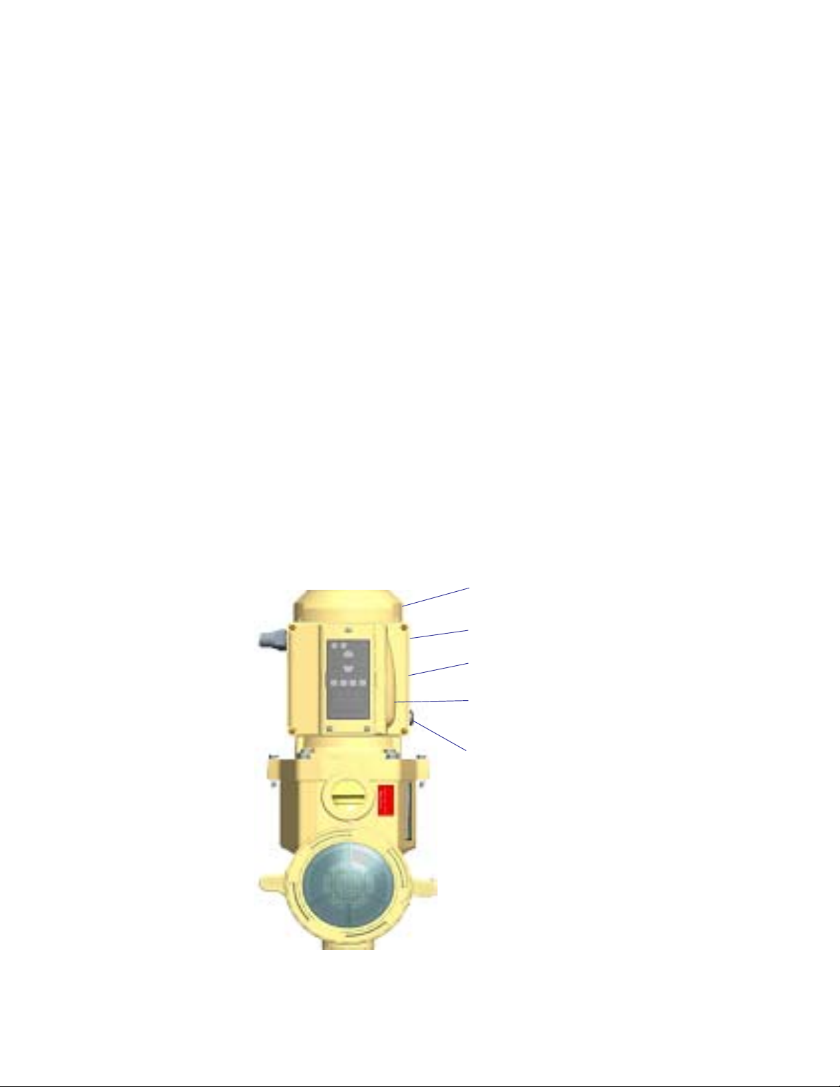
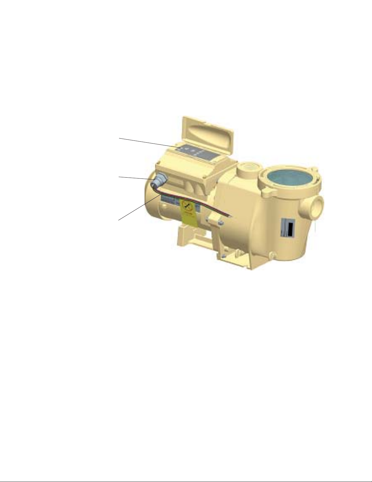
IntelliFlo VS-3050 Motor Assembly
The IntelliFlo three-phase six-pole motor operates at 3450 RPM (at 92% efficiency) and 1000 RPM (at
90%). The drive assembly is continually cooled by an external fan. Dual seals on the motor shaft and at the
fan assembly seal the entire motor from any moisture from entering the motor assembly . For added
protection, a slinger located in front of the main shaft seal assists in slinging water away from the shaft
opening in the flange.
Motor fan cover
Motor assembly
Drive assembly and
electronics enclosure
Control panel cover
Communication port for
connection to EasyTouch,
IntelliTouch or SunTouch control
system or IntelliComm
communicaton center via twowire RS-485 cable
IntelliFlo VS-3050 Motor Assembly
IntelliFlo VS-3050 Installation and User’s Guide
Page 9
IntelliFlo VS-3050 Drive Assembly and Control Panel
The IntelliFlo drive assembly consists of an operator control panel and the system electronics that drive the
motor. The drive microprocessor controls the motor by changing the frequency of the current it receives
together with changing the voltage to control the rotational speed.
Operator Control Panel,
buttons and LEDs
¾” NPT male threaded
PVC nipple
3
Three Wire Harness
Red (hot), Red (hot),
Green (Ground)
+/- 20% of 230 Volt
IntelliFlo VS-3050 Drive Assembly
IntelliFlo VS-3050 Motor Features
• Permanent Magnet Synchronous Motor (PMSM)
• High efficiency (3450 RPM 92% and 1000 RPM 90%)
• Superior speed control
• Operates at lower temperatures due to high efficiency
• Same technology as deployed in hybrid electric vehicles
• Designed to withstand outdoor environment
• T otally enclosed fan cooled
• Three-phase motor
• 56 Square Flange
• Six-Pole
• Low noise
IntelliFlo VS-3050 Installation and User’s Guide
Page 10
4
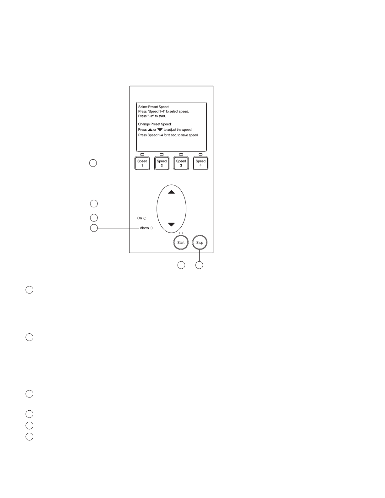
IntelliFlo VS-3050 Operator Control Panel
The IntelliFlo VS-3050 operator control panel provides manual speed controls for the pump. There are four
preset speed buttons that can be selected. The Up and Down button is used to adjust the pump speed. The
selected speed can be saved and assigned to one of the speed buttons.
IntelliFlo
®
1
2
5
6
3 4
Controls and LEDs
1
Speed 1, Speed 2, Speed 3, and Speed 4 button/LED: Press one of the speed buttons to select the
desired preset pump speed. The pump preset speeds are: Speed 1 (750 RPM), Speed 2 (1500 RPM),
Speed 3 (2350 RPM), and Speed 4 (3110 RPM). The speed button LED is on when the selected button
is pressed. If the pump is running and the Up/Down button is used to adjust the speed, the selected speed
LEDs will go off. For more about using the speed buttons, see page 5.
2
Up/Down button: While the pump is running, press the Up or Down button to increase or decrease the
pump speed. T o save the new pump speed, press any one of the four speed buttons for three seconds to
assign the speed to the selected button (the LED be on). Four adjusted pump speeds can be assigned to the
speed buttons. When the pump is using an adjusted speed and the pump is powered down, the next time
the pump is powered up the pump will use the same speed. For more about using the Up/Down button, see
page 5.
3
Start button/LED: Starts the pump using a selected or adjusted speed. This LED is on when the pump is
running.
4
Stop button: Press this button to stop the pump.
5
On LED: This green power LED is on when IntelliFlo is powered up.
6
Alarm LED: This LED is on when an error condition occurs. This green LED will flash a certain number of
times indicating a specific error condition. For the alarm LED flash sequence, refer to “Alarm and W arning
LED Sequence,” on page 29.
IntelliFlo VS-3050 Installation and User’s Guide
Page 11

Section 2
Operating IntelliFlo VS-3050
This section describes how to use the IntelliFlo VS-3050 pump control panel.
Setting the pump preset speed
IntelliFlo operates using one of the preset speeds. Use the speed buttons to select the preset speeds.
To set the pump speed
1. Ensure that the pump is powered on and the green power LED is on.
2. Press the desired speed button (1- 4) for less than three seconds to select the preset pump speed.
When the selected speed button is pressed, the LED is on. The pump preset buttons and speeds are:
Speed 1 button - 750 RPM
Speed 2 button - 1500 RPM
Speed 3 button - 2350 RPM
Speed 4 button - 31 10 RPM
5
3. Press the Start button to start the pump using the selected speed if necessary .
Adjusting the pump speed
IntelliFlo can be adjusted to run at any speed between 400 RPM and 3450 RPM.
To adjust the pump speed
1. Ensure that the pump is powered on and the green power LED is on.
2. Press the Start button to start the pump if the pump is not running.
3. Press the UP/Down button to increase or decrease the pump speed.
• 10 RPM increments: Press and quickly release the Up/Down button to
increase or decrease the speed in 10 RPM increments.
• 20 RPM increments: Press and hold the Up/Down button to continuously
increase or decrease the pump speed.
4. Saving an adjusted speed: To save the newly adjusted pump speed, press and
hold the desired speed buttons to assign the current speed. Four new pump
speeds can be assigned to Speed buttons (1-4).
5. Press the Speed button that is assigned to the adjusted speed.
Up/Down button
IntelliFlo VS-3050 Installation and User’s Guide
Page 12

6
Starting the pump
To start the pump
1. Ensure that the pump is powered on and the green power LED is on.
2. Press the Start button (LED on) to start the pump.
Note: When the pump is using a modified speed and is powered down, the next time the pump is
powered up, the pump will use that same speed.
Stopping the pump
To stop the pump
• Press the Stop button to stop the pump.
Note: The pump can automatically restart if the communication cable is connected.
Resetting the pump to factory defaults
The IntelliFlo VS-3050 pump can be reset to the factory default settings. All previously adjusted pump speeds
that were saved will be erased.
T o reset the pump to the factory default settings:
1. Ensure that the pump is powered on and the green power LED is on.
2. Press the Stop button to stop the pump.
3. Press and hold all of the four Speed buttons simultaneously for four seconds. Power off the drive
and reenergize. The default settings will be in effect.
Control Panel Speed Buttons
Assigning a pump address for remote control
The default communications address for the IntelliFlo is 1. This is the only IntelliFlo address that the EasyT ouch
and IntelliComm systems will communicate with. Therefore these devices can only communicate with one
IntelliFlo. The IntelliT ouch is able to communicate with four Intelliflo pumps. If more than one IntelliFlo is being
used with an IntelliT ouch the 2nd, 3rd and 4th pumps will have to be readdressed as described below .
T o assign a pump an address:
1. Be sure that the pump is powered on and the green power LED is on.
2. Press the Stop buttons to stop the pump.
3. Press and hold both the Start and Stop buttons until the red LED will starts flashing, then press one
of the four speed buttons to select which address to assign the pump.
4. Press and hold both the Start and S top buttons to save the address. Repeat the process for the
other pumps.
IntelliFlo VS-3050 Installation and User’s Guide
Page 13

Priming the pump for the first time, or after service
Before the IntelliFlo VS-3050 pump is started for the first time it must be primed. T o prime a pump means
filling the pump and suction pipe with water. This process evacuates the air from all the suction lines and the
pump. It may take several minutes to prime depending on the depth of water, pipe size and length. It is
easier to prime a pump if you allow all the air to escape from the pump and pipes. The water cannot enter
unless the air can escape. Pumps do not hold prime, the pool piping system has that task.
CAUTION - T o avoid permanent damage to the IntelliFlo pump, before starting the pump, fill the IntelliFlo
housing strainer with water so that the pump will prime correctly . If there is no water in the stainer the pump will
not prime.
• NEVER run the pump dry! Running the pump dry may damage the seals, causing leakage and
flooding!
• Do not add chemicals to the system directly in front of pump suction. Adding undiluted chemicals
may damage the pump and will void the warranty .
• Open gate valves before starting system.
• Pump will prime itself when used in flooded suction system.
• Be sure to release all air from filter and piping system.
• The IntelliFlo pump is a variable speed pump. Typically the lower speeds are used for filtration and
heating. The higher speeds can be used for spa jets, water features, and priming.
7
CAUTION - Before starting this procedure, first read the following
Before removing the pump lid:
Lid
Clamp
1. Press the Stop button if the pump is running before proceeding.
2. Disconnect the communication cable from the pump.
3. Disconnect main power supply
Volute
4. Close the gate valves in suction and discharge pipes.
5. Release all pressure from pump and piping system.
6. Never tighten or loosen the clamp while the pump is operating.
WARNING! If the pump is being pressure tested, release all pressure before removing the trap cover .
Do not block the pump suction while the pump is running. If a body part blocks the pump suction it may cause
severe or fatal injury . Small children using the pool must AL WAYS have close adult supervision.
WARNING! FIRE and BURN HAZARD - The pump motor may run at a high temperatures. To reduce the
risk of fire, do not allow leaves, debris, or foreign matter to collect around the pump motor. T o avoid burns when
handling the motor, shut of f the motor and allow it to cool for 20 minutes before trying to work on it. The IntelliFlo
provides an automatic internal cutoff switch to protect the motor from heat damage during operation.
IntelliFlo VS-3050 Installation and User’s Guide
Page 14

8
Priming the pump for the first time, or after service (Continued)
Priming the Pump
• Release all pressure from filter, pump, and piping system; see the filter owner’ s manual.
• In a flooded suction system (water source higher than pump), the IntelliFlo VS-3050 pump will
prime itself when suction and discharge valves are opened.
• If the IntelliFlo pump is not in a flooded suction system, unscrew and remove lid cover; fill the and
pump with water.
• Do not lubricate the trap cover o-ring. The original equipment o-ring contains a permanent internal
lubricant.
NOTICE: If you replace the o-ring with a non-internally lubricated o-ring, you may need to apply a silicone
based lubricant.
• Clean and inspect o-ring; reinstall on trap cover.
• Replace trap cover on trap; turn clockwise to tighten cover.
NOTICE: Tighten the pump lid by hand only (no wrenches)!
Pump should prime now . Priming time will depend on vertical length of suction lift and horizontal length of
suction piping. If pump does not prime, make sure that all valves are open, suction pipe end is under water,
pump suction is below water level, and that there are no leaks in suction pipe.
T o prime the IntelliFlo pump:
1. Turn the pump clamp and lid in a counterclockwise direction until it stops
and remove them.
Clamp
Lid
2. Fill the pump strainer pot with water.
3. Reinstall the pump clamp and lid onto the strainer pot. The pump is now
ready to prime.
4. Make sure all electrical connections are clean and tight.
Volute
5. Open the air release valve on the filter, and stand clear of the filter.
6. Switch the IntelliFlo pump on at the circuit breaker. Ensure that the
green power light is on.
Top view
7. Press the Speed 1 button to select the pump speed of 750 RPM.
8. Press the Start button to start the pump. Use the Up/Down button to increase the speed as necessary
to prime the pump.
9. When water comes out of the air release valve, close the valve. The system should now be circulating water
back to the pool without air bubbles showing in either the hair and lint pot or at the pool return fittings.
10. Use the Up/Down button to adjust the operating speed as desired.
IntelliFlo VS-3050 Installation and User’s Guide
Page 15

External Control with IntelliComm Communication Center
The IntelliFlo VS-3050 can be remotely controlled by the Pentair IntelliComm Communication Center
using an optional communications cable (P/N 350122). The IntelliComm provides four pairs of input
terminal connections. These inputs are actuated by either 15 - 240 VAC or 15 - 100 VDC. Using the
device's inputs, the programmed IntelliFlo pump speeds can be controlled.
If more than one input is active the highest number will be communicated to the IntelliFlo pump. The
IntelliComm will always communicate to pump address 1.
The following table shows the wiring terminal descriptions for IntelliComm.
External Control
9
Terminals
IntelliComm Communication Center
rebmunlanimreTemanlanimreTegatloV
2-1ylppusrewoPCAV042-001Am001tupnI1zH06/05
CAV042-51
31margorP
4-
6-52margorP
8-73margorP
01-94margorP
11
21
584-SR
wolleY:ataD+
eerG:ataD-
n
ro
CDV001-51
CAV042-51
ro
CDV001-51
042-51
CAV
ro
CDV001-51
CAV042-51
ro
CDV001-51
CDV5+ot5-
mumixaM
tnerruc
*Am1tupnI1zH06/05
*Am1tupnI1zH06/05
*Am1tupnI1zH06/05
*Am1tupnI1zH06/05
Am5tuptuO1A/N
epytesahPycneuqerF
dnuorG
IntelliFlo VS-3050 Installation and User’s Guide
Page 16

10
Connecting IntelliFlo VS-3050 to an EasyTouch System
The IntelliFlo can be controlled by an EasyT ouch system via the RS-485 communication cable
(P/N 350122). In this configuration, EasyT ouch starts, stops and controls the speed of the IntelliFlo pump.
When the EasyT ouch does this, it rewrites the IntelliFlo memory, which can take several seconds. This
causes a delay after a command is given on the EasyT ouch control panel until the IntelliFlo physically
responds.
The IntelliFlo control panel is disabled when communicating with the EasyT ouch system. Note that
IntelliT ouch will not start communicating with the IntelliFlo until the pump is assigned to a circuit. The
IntelliFlo default pump address is one which is the only address that works with EasyT ouch. See page 6 for
details about how to check the address and change if necessary . For more information, refer to the
EasyT ouch User's Guide (P/N 520584).
T o connect the IntelliFlo communication cable to EasyT ouch load center:
1. CAUTION - Switch the main power off to the EasyT ouch load center.
2. Unlatch the two enclosure door spring latches, and open the door.
3. Remove the two retaining screws securing the high voltage cover panel, and remove it from the
enclosure.
4. Loosen the two access screws securing the control panel.
Control panel
access screw
Control panel
access screw
Retaining screw
High voltage
cover panel
EasyTouch Load Center (front view)
IntelliFlo VS-3050 Installation and User’s Guide
Page 17

5. Lower down the hinged control panel to access the EasyT ouch motherboard.
6. Route the communication cable into the lower plastic grommet, up through the low voltage raceway
to the EasyT ouch load center motherboard.
Control panel
motherboard
Low voltage
Raceway
11
7. Strip back the cable conductors ¼ inch. Insert the two wires into the screw terminals on the board.
Secure the wires with the screws.
8. EasyTouch to IntelliFlo pin configuration:
• IntelliFlo: Connect pin 6 (green) to EasyT ouch screw terminal pin 2 (green)
• IntelliFlo: Connect pin 7 (yellow) to EasyT ouch screw terminal pin 3 (yellow)
EasyTouch (J20)
screw terminal
hcuoTysaE
lanimretwercs
rotcennoc
)NRG(2)6niP(NEERG
)LEY(3)7niP(OLLEY
Pin configuration
olFilletnI
)elbaceriw-2(
Pin 6
(Green)
Pin 7 (Yellow)
IntelliFlo connector pin configuration
9. Insert the screw terminal onto the EasyTouch COMPOR T (J20) board connector . Note: Multiple
wires may be inserted into a single screw terminal.
Indoor Control Panel
IntelliChlor
IntelliFlo
RF Transceiver
EasyTouch
COMPORT
(J20)
IntelliFlo VS-3050 Installation and User’s Guide
Page 18

12
10. Close the control panel into its original position and secure it with the two access screws.
11. Install the high voltage cover panel and secure it with the two retaining screws.
12. Close the EasyTouch load center front door . Fasten the two spring latches.
13. Switch the power on to the EasyTouch load center .
Control panel
Control panel
access screw
access screw
EasyTouch Load Center (front view)
Retaining screw
High voltage
cover panel
IntelliFlo VS-3050 Installation and User’s Guide
Page 19

Connecting IntelliFlo VS-3050 to an IntelliTouch System
The IntelliFlo VS-3050 can be controlled by an IntelliT ouch system via the RS-485 communication cable
(P/N 350122). In this configuration, IntelliT ouch starts, stops and controls the speed of the IntelliFlo pump.
When the IntelliT ouch does this, it rewrites the IntelliFlo memory, which can take several seconds. This
causes a delay after a command is given on the IntelliT ouch control panel until the Intelliflo physically
responds.
The IntelliFlo control panel is disabled when communicating with the IntelliT ouch system. Note that
IntelliT ouch will not start communicating with the IntelliFlo until the appropriate pump address is assigned to
a circuit. The IntelliFlo default pump address is one. See page 6 for details about how to check the address
and change if necessary . For more information, refer to the IntelliT ouch User's Guide (P/N 520102).
T o connect the IntelliFlo communication cable to IntelliTouch load center:
13
1.
CAUTION - Switch the main power off to the IntelliTouch load center.
2. Unlatch the IntelliTouch load center front door spring latches, and open the front door .
3. Remove the cover-panel screws securing the high voltage cover-panel, and remove it from the
enclosure.
4. Loosen the two control panel access screws and fold down the outdoor control panel.
5. Insert the two-wire cable into plastic grommet on the bottom of the enclosure and route the wire up
through the low voltage raceway to the Personality board.
Personality Board
Access
screw
Low voltage raceway
Plastic grommet
Cover-panel
screw
(Cover-panel not
shown)
IntelliT ouch Load Center
IntelliFlo VS-3050 Installation and User’s Guide
Page 20

14
6. Strip back the cable conductors ¼”. Insert the wires into the either of the COM PORTS
(J7 andJ8) screw terminals located on the left side of the Personality board. Secure the wires with
the screws. For wiring details, refer to ”Pin Configuration” shown below . Note: Multiple wires may
be inserted into a single screw terminal. Strip back the cable conductors ¼ inch. Insert the two
wires into the screw terminals on the board. Secure the wires with the screws.
.
IntelliTouch Personality
board COM PORT
(J7/J8)
BLK
GRN
YEL
RED
Pin Configuration IntelliFlo to IntelliT ouch pin configuration:
• IntelliFlo: Connect pin 6 (green) to IntelliT ouch screw terminal pin 2 (green)
• IntelliFlo: Connect pin 7 (yellow) to IntelliT ouch screw terminal pin 3 (yellow)
IntelliTouch COM port (J7/J8)
screw terminal
hcuoTilletnI
lanimretwercs
rotcennoc
)NRG(2)6niP(NEERG
)LEY(3)7niP(OLLEY
Pin configuration
olFilletnI
)elbaceriw-2(
Pin 6
(Green)
Pin 7 (Yellow)
IntelliFlo connector pin configuration
7. Close the control panel into its original position and secure it with the two access screws.
8. Install the high voltage cover panel and secure it with the two retaining screws.
9. Close the load center front door. Fasten the two spring latches.
10. Switch the power on to the load center.
IntelliFlo VS-3050 Installation and User’s Guide
Page 21

Connecting IntelliFlo VS-3050 to a SunTouch System
ONLY
SOLAR
CLNR
The IntelliFlo VS-3050 can be controlled by a SunT ouch system via the RS-485 communication cable
(P/N 350122). T o connect the two wire RS-485 cable from the IntelliFlo VS-3050 drive assembly to the
motherboard located in the SunT ouch Power Center:
WARNING - Switch OFF main system power to the SunTouch Power Center before making any connections.
T o access the SunT ouch Power Center electronics compartment:
1. Unlatch the front door of the SunTouch Power Center , and open the door.
2. Loosen the retaining screw on front panel. Open the hinged front panel to access the electronics
compartment.
3. Route the two conductor cable up through the Power Center grommet opening located on the left
side, and up through the low voltage raceway to the motherboard.
4. Strip back the cable conductors ¼ in. Insert the wires into the screw terminals (provided in the kit).
Secure the wires with the screws. Make sure to match the color coding of the wires; Yellow = +DT,
Green = -DT .
15
5. Insert the connector on the COMPORT (J1 1) screw terminal on the motherboard.
6. When the connection is completed, close the control panel and secure it with the retaining screw.
7. Close the front door. Fasten the spring latch.
Pin 6
(Green)
Pin 7 (Yellow)
IntelliFlo cable pin configuration
SunT ouch Motherboard
SunTouch
COM PORT (J11)
screw terminal
Pin configuration
hcuoTnuS
lanimretwercs
rotcennoc
)NRG(2)6niP(NEERG
)LEY(3)7niP(WOLLEY
GAS
HEATER
RESET
olFilletnI
)elbaceriw-2(
J11
COM PORT
RS-485 communication
cable (P/N 350122)
IntelliFlo
VS-3050
Drive
VLV A
VALVE ACTUATORS
VLV B
VLV C
SOLAR
ONLY
CLNR
INTAKE
RETURN
SOLAR
PUMP
AUX 1
AUX 2
AUX 3
230 VAC
Power to Pump
IntelliFlo VS-3050 Installation and User’s Guide
Page 22

16
Blank Page
IntelliFlo VS-3050 Installation and User’s Guide
Page 23

Section 3
User Maintenance
The following information describes how to service and maintain the IntelliFlo VS-3050 pump.
Pump Strainer Basket
The strainer, sometimes referred to as the “Hair and Lint Pot,” is in front of the of the pump. Inside there is
a basket which must be kept clean of leaves and debris at all times. V iew the basket through the top see
through lid to inspect for leaves and debris.
Regardless of the length of time between filter cleaning, it is most important to visually inspect the hair and lint
pot basket at least once a week. A dirty basket will reduce the efficiency of the filter and possibly the heater .
WARNING — DO NOT open the strainer pot if pump fails to prime or if pump has been operating without
water in the strainer pot. Pumps operated in these circumstances may experience a build up
of vapor pressure and may contain scalding hot water. Opening the pump may cause serious
personal injury . In order to avoid the possibility of personal injury , make sure the suction and
discharge valves are open and that the strainer pot is cool to the touch, then open with
extreme caution.
17
CAUTION — T o prevent damage to the pump and filter and for proper operation of the system, clean
pump strainer and skimmer baskets regularly .
Pump Strainer Basket Service
If the IntelliFlo pump is installed below the water level of the pool,
close the return and suction lines before opening the hair and lint pot
on the pump.
1. Press the Stop button to stop the pump and switch off the pump
at the circuit breaker.
2. Disconnect the communication cable from the IntelliFlo pump.
3. Relieve pressure in the system.
4. Turn the clamp and lid in a counterclockwise direction until it
stops.
5. Remove the clamp and lid.
6. Remove the basket and put the debris into the trash and rinse out
the basket. If the basket is cracked, replace the basket.
7. Replace the basket and fill the pump pot and volute with water
up to the inlet port.
Clamp, pot
Lid
O-ring, lid
Basket
Pot volute
8. Clean the cover, o-ring, and sealing surface of the pump pot. Grease
the o-ring with Teflon or silicone lubricant.
9. Reinstall the lid by placing the clamp and the lid on the pot.
IntelliFlo VS-3050 Installation and User’s Guide
Page 24

18
Pump Strainer Basket Service (Continued)
10. Ensure that the lid o-ring is properly placed. Seat the clamp and lid then
turn clockwise until the handles are horizontal as shown.
11. Reconnect the communication cable to the pump if required.
12. Switch the power ON at the circuit breaker. Reset the pool time clock
to the correct time.
WARNING — FIL TER OPERA TES UNDER HIGH PRESSURE. WHEN
ANY PART OF THE CIRCULATING SYSTEM (e.g., LOCK RING,
PUMP, FILTER, VALVES, ETC.) IS SERVICED, AIR CAN ENTER
THE SYSTEM AND BECOME PRESSURIZED. PRESSURIZED
AIR CAN CAUSE THE LID TO BLOW OFF WHICH CAN RESULT
IN SEVERE INJURY, DEATH, OR PROPERTY DAMAGE. TO AVOID THIS
POTENTIAL HAZARD, FOLLOW THESE INSTRUCTIONS.
13. Open the manual air relief valve on top of the filter.
14. Stand clear of the filter. Press the Start button on the pump.
15. Bleed air from the filter until a steady stream of water comes out.
16. Close the manual air relief valve.
Motor Service
Clamp
Lid
Volute
1. Protect from heat:
• Shade the motor and controller from the sun.
• Any enclosure must be well ventilated to prevent overheating. Particular attention should be paid to the
motor fan cover and the cooling fins between the drive and the motor.
• Provide ample cross ventilation.
2. Protect against dirt:
• Protect from any foreign matter or splashing water.
• Do not store (or spill) pool chemicals near the motor.
• Avoid sweeping or stirring up dust near the motor while it is operating.
• If a motor has been damaged by dirt it voids the motor warranty.
3. Protect against moisture:
• Protect from splashing pool water.
• Protect from the weather.
• Protect from lawn sprinklers.
• If a motor has become wet - let it dry before operating. Do not allow the pump to operate if it has been
flooded.
• If a motor has been damaged by water it voids the motor warranty.
Note: DO NOT wrap motor and controller with plastic or other air tight materials. The motor and
controller may be covered, but not wrapped in plastic, during a storm, for winter storage, etc., but
never when operating, or expecting operation.
When replacing the motor, be certain that the motor support is correctly positioned to support the size of
motor being installed.
IntelliFlo VS-3050 Installation and User’s Guide
Page 25

Winterizing
T o protect the IntelliFlo pump electronics from damage due to freezing conditions, the pump will switch it
self on to generate internal heat when the air temperature drops below 40° F . This feature is not intended to
protect the system plumbing from freezing.
1. If the air temperature drops below 40° F the water in the pump can freeze and cause damage.
Freeze damage is not warrantable.
2. To prevent freeze damage follow the procedures listed below.
• Shut off electrical power for the pump at the circuit breaker.
• Drain the water out of the pump by removing the two thumb-twist drain plugs located at the bottom of
the volute. Store the plugs in the pump basket.
• Cover the motor to protect it from severe rain, snow and ice.
• Do not wrap the motor in plastic. It will cause condensation and rust on the inside of the motor.
Note: In mild climate areas, when temporary freezing conditions may occur, run your filtering equipment
all night to prevent freezing.
Priming the pump after service
19
Before a system start-up, the pump and system must be manually primed. Make sure to reopen valves
before operating. T o prime IntelliFlo, the strainer pot must be filled with water.
CAUTION — DO NOT run the pump dry. If the pump is run dry, the mechanical seal will be damaged and
the pump will start leaking. If this occurs, the damaged seal must be replaced. A LWAYS
maintain proper water level in your pool. Continued operation in this manner could cause
a loss of pressure, resulting in damage to the pump case, impeller and seal.
For instructions about how to prime the IntelliFlo pump, refer to “Priming the pump for the first time or after
servicing,” on page 7.
IntelliFlo VS-3050 Installation and User’s Guide
Page 26

20
Blank Page
IntelliFlo VS-3050 Installation and User’s Guide
Page 27

Section 4
Installation and Removal
The following information describes how to install the IntelliFlo VS-3050 pump.
Note: Before installing this product, read and follow all warning notices and instructions on page ii.
IntelliFlo VS-3050 Kit Contents
• IntelliFlo VS-3050 pump
Installing the IntelliFlo
Only a qualified service person should install the IntelliFlo pump.
Location
1. Install the pump as close to the pool or spa as possible. To reduce friction loss and improve efficiency,
use short and direct suction and piping returns.
21
2. Install a minimum of five (5) feet from the inside wall of the pool and spa. Canadian installations require
a minimum of three (3) meters from pool water.
3. Install the pump a minimum of two (2) feet from the heater outlet.
4. Do not install the pump more than (8) feet above the water level.
5. Install the pump in a sheltered well ventilated location protected from excessive moisture, (i.e., rain,
sprinklers, etc.).
6. For hot tubs and spas, do not install within an outer enclosure or beneath the skirt of a hot tub or spa.
7. Install the pump with a rear clearance of at least 6 inches so that the motor can be removed easily for
maintenance and repair.
Piping
For improved pool plumbing, it is recommended to use a larger pipe size. When installing the inlet and outlet
fittings (male adaptors), use thread sealant. Do NOT use T eflon® tape.
Do not install 90° elbows directly into pump inlet or outlet. A valve, elbow or tee installed in the suction line
should be no closer to the front of the pump than five (5) times the suction line pipe diameter (i.e., two (2)
inch pipe requires a ten (10) inch straight run in front of the suction inlet of the pump). This will help the
pump prime faster and last longer.
Flooded suction systems should have gate valves installed on suction and discharge pipes for maintenance,
however, the suction gate valve should be no closer than five (5) times the suction pipe diameter as
described above.
Check Valve
Check valves must be used when the IntelliFlo is used in parallel with other pumps. IntelliFlo pumps cannot
be used in series with other pumps.
IntelliFlo VS-3050 Installation and User’s Guide
Page 28

22
Wiring the IntelliFlo VS-3050
T o connect the IntelliFlo to an AC power source:
1. Make sure all electrical breakers and switches are turned off before wiring motor.
2. Make sure that the wiring voltage is 230 VAC ± 10%.
3. Use #12 AWG for wire runs up to 100 feet and #10 AWG for lengths longer than 100 feet. When in
doubt use a heavier gauge (larger diameter) wire. Heavier gauge will allow the motor to run cooler and
more efficient.
4. Make sure all electrical connections are clean and tight.
5. Cut the wires to the appropriate length so they do not overlap or touch when connected.
6. Permanently ground the motor using the green ground wire, as shown below. Use the correct wire size
and type specified by National Electrical Code. Make sure the ground wire is connected to an electrical
service ground.
7. Bond the motor to the pool structure in accordance with the National Electrical Code. Use a solid
No. 8 AWG or larger copper conductor. Run a wire from the external bonding lug to the pool bonding
structure, as shown below.
8. Permanently connect the pump to a non-GFCI circuit breaker, two-pole timer or relay in an automation
controller such as IntelliTouch, EasyTouch or IntelliComm, the drive must be powered up to receive and
respond to the RS-485 serial communication from the automation system. Be sure that no other lights or
appliances are on the same circuit.
NOTE: The IntelliFlo pump will not function properly when powered from a GFCI device.
NOTE: When the IntelliFlo pump is started and stopped by removing power with a relay or
timer, a two-pole device should be used to apply and remove power to both of the red power
leads.
The IntelliFlo is designed to be permanently connected to its power source. Typically the pump receives
power directly from the circuit breaker. No contactor or motor starter is required. IntelliFlo can be
operated in “stand-alone” mode, starting and stopping when power is applied or removed. When the drive
powers up it will return to the mode and run status that it was in when power was removed. This setup
maybe appropriate if you need to use existing relays or timers.
9. For wiring pinouts for the communications port, see pages 11, 14 and 15.
GROUND WIRE
(GREEN)
IntelliFlo 4 wiring harness
Red = Hot
Red = Hot
Green/yellow stripe = Ground
IntelliFlo VS-3050 Installation and User’s Guide
BONDING LUG
Page 29

Pump Disassembly
W ARNING — Always disconnect power to the pool pump at the circuit breaker and disconnect the
communication cable before servicing the pump. Failure to do so could result in death or
serious injury to serviceman, pool users or others due to electric shock.
Read all servicing instructions before working on the pump.
WARNING — DO NO T open the strainer pot if pump fails to prime or if pump has been operating without
water in the strainer pot. Pumps operated in these circumstances may experience a build up
of vapor pressure and may contain scalding hot water. Opening the pump may cause serious
personal injury. In order to avoid the possibility of personal injury, make sure the suction and
discharge valves are open and strainer pot temperature is cool to touch, then open with
extreme caution.
CAUTION — Be sure not to scratch or mar the polished shaft seal faces; seal will leak if faces are
damaged.
All moving parts are located in the rear subassembly of the IntelliFlo pump.
T ools required:
23
• 3/32 inch Allen head wrench.
• ½ inch open end wrench.
• 9/16 inch open end wrench.
• Flat blade screwdriver.
T o remove and repair the pump mechanical seal, perform the following procedures:
1. Switch off the pump circuit breaker at the main panel.
2. Disconnect the RS-485 communication cable from the pump.
3. Drain the pump by removing the drain plugs.
4. Remove the six bolts that hold the main pump body (strainer pot/volute) to the rear subassembly.
5. GENTLY pull the two pump halves apart, removing the rear subassembly.
6. Use a 3/32 inch Allen head wrench to loosen the two holding screws located on the diffuser.
7. Hold the impeller securely in place and remove the impeller lock screw by using a Phillips head
screwdriver. The screw is a left-handed thread and loosens in a clockwise direction.
8. Use a flat blade screwdriver to hold the motor shaft. The motor shaft has a slot on the end which is
accessible through the center of the fan cover.
IntelliFlo VS-3050 Installation and User’s Guide
Page 30

24
Pump Disassembly (Continued)
9. T o unscrew the impeller from the
shaft, twist the impeller
counterclockwise.
10. Remove the rotating portion of the
mechanical seal from the impeller.
11. Remove the four bolts from the
seal plate to the motor, using a
9/16 inch wrench.
GASKET
MOTOR
BOLT (4x)
SEAL
O-RING
SET SCREW
12. Place the seal plate face down on
a flat surface and tap out the
carbon spring seat.
13. Clean the seal plate, seal housing,
MOTOR
BOLT (2x)
SEAL PLATE
IMPELLER
LOCK SCREW
LOCK SCREW SEAL
and the motor shaft.
Pump Reassembly/Seal Replacement
1. When installing the replacement shaft seal, use silicone sealant on the metal portion before pressing into
the seal plate as shown.
2. Before installing the rotating portion of the seal into the impeller, be sure the impeller is clean. Use a
light density soap and water to lubricate the inside of the seal. Press the seal into the impeller with your
thumbs and wipe off the ceramic and carbon faces with a clean cloth.
3. Remount the seal plate to the motor.
4. Grease the motor shaft thread and screw impeller onto the motor shaft.
5. Screw in the impeller lock screw (counterclockwise to tighten).
6. Remount the diffuser onto the seal plate. Make sure the plastic pins and holding screw inserts are
aligned.
7. Grease the diffuser o-ring and seal plate gasket prior to reassembly.
8. Grease the bolt threads, assemble the motor subassembly to the strainer pot-pump body by using the
two (2) through bolts for proper alignment. Do not tighten the through bolts until all six (6) bolts are in
place and finger tightened.
9. Reconnect the RS-485 communication cable to the pump.
10. Fill the pump with water.
11 . Reinstall the pump lid and plastic clamp. See “Pump Strainer Basket Service” on page 15 for details.
12. Prime the pump, see page 7.
Shaft Seal Replacement
The Shaft Seal consists primarily of two parts, a rotating member and a ceramic seal. The pump requires little
or no service other than reasonable care, however, a shaft seal may occasionally become damaged and must
be replaced.
Note: The polished and lapped faces of the seal could be damaged if not handled with care.
IntelliFlo VS-3050 Installation and User’s Guide
Page 31

Drive Assembly Removal and Installation
T o remove the IntelliFlo VS-3050 drive and control panel from the motor assembly:
1. Make sure all electrical breakers and switches are turned off before removing the drive.
2. Disconnect the RS-485 communication cable from the pump.
3. Open the control panel cover.
4. Remove the three Phillips head screws securing the drive to the motor assembly as shown.
CAUTION: TO AVOID ELECTRICAL HAZARD, DO NOT REMOVE THE FOUR TAMPER
PROOF BITS FROM THE MOTOR ASSEMBLY
5. Lift up the drive assembly and remove it from the motor adapter located on top of the motor assembly.
Note: Be careful not to remove the gasket between the drive and motor, it is critical in keeping
moisture out of the drive and motor. Replace the gasket if damaged. Do not reassemble with a
damaged or missing gasket.
T o install the IntelliFlo drive assembly onto the motor assembly:
1. Make sure all electrical breakers and switches are turned off before installing the drive.
25
2. Be sure that the gasket between the drive and motor is in place. It is critical in keeping moisture out of
the drive and motor. Replace the gasket if damaged. Do not reassemble with a damaged or missing
gasket.
3. Verify that the three (3) orange motor post caps are in position before placing the drive on the motor
assembly.
4. Align the drive assembly with the motor adapter and seat the drive on the motor assembly.
5. Secure and tighten the drive assembly with the three Phillips head screws.
Phillips head screw
Phillips head screws
Do not remove
these screws
Adapter connector
Orange motor post
caps (QTY. 3)
Gasket
IntelliFlo VS-3050 Installation and User’s Guide
Page 32

26
Illustrated Parts List
28
26
25
23
4
2
22
24
3
15
11
32
31
20
10
1
21
30
Replacement Parts
Item Part Description
No. No.
1 070387 BASKET AQ & WF
2 070429 BOLT HEX HD, 2-56x0.875 s/s,
(QTY 4)
3 070430 BOLT 3/8 - 16 X 1¼ HEX CAP 18-8 s/s,
(QTY 4)
4 070431 BOLT 3/8 -16 X 2 HEX CAP 18-8 s/s,
(QTY 2)
5 070927 FOOT WF - PUMP MOTOR SUPPORT
6 070929 FOOT INSERT WF PUMP
7 071131 PLUG DRAIN WFE (Almond) (QTY 2)
8 071403 NUT 3/8 - 16 BRASS NICKEL PLATED,
(QTY 2)
9 071406 NUT ¼ - 20 HEX s/s (QTY 2)
10 071444 O-RING 238, 3.484x0.139, Buna-N 70
11 071652 SCREW ¼-20 X 1 LH PHILLIPS PAN
MS 18-8 s/s
12 071657 SCREW ¼ - 20 X 1 in. HEX CAP 18-8 s/s,
(QTY 3)
13 071660 SCREW SET 4-40 X 1-1/8 WFE SCKT
CAP 18-8 s/s (QTY 2)
14 072183 WASHER FLA T ¼ X 5/8 20 GA THICK
18-8 s/s (QTY 2)
27
17
19
16
13
Item Part Description
28* 350521 INTELLIFLO 4 SPEED DRIVE
14
5
12
28
No. No.
15 072184 WASHER 3/8 ID X 7/8 OD .05 THICK
16 072928 DIFFUSER ASSEMBL Y WFE 12
17 073131 IMPELLER WFE 12 1000 SER
18 074629 GASKET FLA T WASHER WFE DRAIN,
19 075713 RUBBER WASHER WFE PUMP
20 350013 O-RING LID CH/WF 2-436
21 350015 VOLUTE CASING WFE (Almond)
22* 350082 CONTROL COVER ASSEMBL Y
23* 350105 VFD MOTOR 3.2KW PMSM
24 350107 SCREW 10-24 X 3¼ in. PH MS 18-8 s/s,
25 350108 INTELLIFLO DRIVE GASKET
26 350142 SPACER CAP (QTY 3)
27 350201 SEAL PLA TE KIT, WFE ALMOND
30 357102 GASKET SANTOPRENE MOLDED
31 357151 LID SEE THRU WF
32 357199 CLAMP CAM & RAMP WF (Almond)
9
8
7
(QTY 2)
(QTY 3)
18
18-8 s/s, (QTY 6)
IntelliFlo VS-3050 Installation and User’s Guide
Note: (*) Not serviceable parts.
Page 33

IntelliFlo VS-3050 Pump Dimensions
10.78
12.50
23.41
27
Intelliflo VS-3050 Flow and Power vs Flow Pump Curve
IntelliFlo VS-3050 Electrical Specifications
Circuit Protection: Two-pole 20 AMP device at the Electrical Panel.
Input: 230 V AC, 50/60 Hz, 3200 W atts
IntelliFlo VS-3050 Installation and User’s Guide
Page 34

28
Blank Page
IntelliFlo VS-3050 Installation and User’s Guide
Page 35

Section 5
Troubleshooting
CAUTION: Before installing this product, read and follow all warning notices and
instructions on page ii.
Warning and Alarm conditions
The IntelliFlo VS-3050 alarms and warnings are indicated by flashing LEDs on the control panel. For
example, if a “Drive T emperature” warning occurs, the LED will blink two times, then Off, then blink two
times. This sequence is repeated until the condition is cleared.
• W arning condition: If a warning condition occurs the pump will be continue to run but at a reduced
speed. The Green LED executes a sequence of blinks to indicate which alarm or warning has
occurred.
29
• Alarm condition: If an alarm condition occurs the pump will drive stop running. The red LED
flashes continuously to indicate the presence of an alarm. The alarm LEDs will reset when the
condition clears.
Alarm and warning LED sequence
ehtemitforebmuN
knilblliwDEL
2gninraWerutarepmeTevirDerutarepmetevirdevissecxEsahnafrotomehterusnE.1
5mralanwonknUeruliafcinortcelE.pmupt
6mralAerutarepmeTevirDerutarepmetevirdevissecxEsahnafrotomehterusnE.1
7mralAtuOrewoPwolegatlovylppuS.
8mralAtnerrucrevOtnerrucevirdevissecxElacinahcem/diulfenimaxE.1
9mralAegatlovrevO ssubevirdnoegatlovevissecxEsdeepsneewtebgnihctiwsdipaR.1
mralAnoitpircseDnoitcA
.noitalitnevrofaeraetauqeda
twolladnarotompotS.2
.looco
otdeepsrehgihatarotomnuR.3
.wolfriagniloocevorpmi
eserotrewopelcyC.1
.evirdecalpeR.2
.n
oitalitnevrofaeraetauqeda
otdeepsrehgihatarotomnuR.2
.wolfriagniloocevorpmi
egatlovylppusreporperusnE
srofmetsys
.evirdecalpeR.3
sreporperusnE.2
.daolrevofoecruo
dnarotomezigrene-eD.2
.yleerfsnipsrotomfienimreted
segatlovevissecxeesuacnac
.ssubCDs'evirdehtno
.egatlovylppu
IntelliFlo VS-3050 Installation and User’s Guide
Page 36

30
General IntelliFlo VS-3050 Troubleshooting Problems
Use the following general troubleshooting information to resolve possible problems with your IntelliFlo pump.
Note: Switch the main power of f to the pump before attempting service or repair.
melborPesuaCelbissoP noitcAevitcerroC
otrefeR.eruliafpmuP
DELgninrawdnamralA
.92egapnoecneuqes
P
.daehro
R
.92egapno
/dnayticapacdecudeR
dnamralAotrefe
ecneuqesDELgninraw
.rellepmideggolC
elriA-emirptonlliwpmuP
.deggolcreniartspmuP
.evitcefedteksagreniartspmu
.noitcusnika
.sevlav
amdna
.ecalp
.retawhguonetoN-emirptonlliwpmuP
.enilnoitcusniskaelrotekcopriA
niarts,pmup
.retawfollufera
.teksagecalpeR
agnipipnoitcuskcehC
.pmup
omeR
.etulovehtmorfyawa
omerebtonnacsirbed
evlavdnagnipipnoitcuskcehC
etagnoitcusynanosdnalg
topreniartspmupnodileruceS
nisiteksagdilerusek
erusekamotlevelretawkcehC
.riagniwardtonsiremmiks
,senilnoitcusehttahterusnE
etulovpmupdna,re
.topreniartspmupnaelC
evlavdn
.sevlavetagnitcusynanosdnalg
ehtotrewoplacirtceleffonruT
sdlohtahtstlob)6(ehtev
.etalplaesehtotetuloveht
etalplaesdnarotomehtedilS
fI.rellepmimorfsirbednaelC
,dev
.spetsgniwollofehtetelpmoc
.gnir-odnaresuffidevomeR.1
.gnir-odnatlobnips
.rellepmi
.gnir-o
dllatsnieR
.etulovotni
.yl
eruces
.deggolcreniartspmuP
.partnoitcusnaelC
-itnadaerhtdnahtfelevomeR.2
llatsnierdnanaelc,evomeR.3
dnatlobnips-itnallatsnieR.4
.gnir-odna,resuffi
etalplaesdnarotomllatsnieR
laesdnuorastlob)6(llatsnieR
nethgitdnaetulovdnaetalp
IntelliFlo VS-3050 Installation and User’s Guide
Page 37

Problems and Corrective Action (Continued)
melborPesuaCelbissoP noitcAevitcerroC
31
spirtrekaerbtiucriC
.yldetaeper
dnamralAotrefeR
ecneuqesDELgninraw
.92
egapno
.me
lborplacirtcelE
dnamralAotrefeR
ecneuqesDELgninraw
.92egapno
selbuorTlacinahceM
dna
.esioN
.tluafICFG
.tnerrucrotomevissecxE
.tohootebyampmuP nahtsselfi;egatlovenilkcehC
.esionduolhtiwtubgninnursirotompmupehT
etauqedafoebtsumrekaerB
tset,rekaerbICFGroF.yticapac
cca
.naicirtcele
eR
.fforotom
ICFGotgnidro
.snoitcurtsnis’rerutcafunam
dnasthgilrehtooneruseB
egatloV.tiucricnoerasecnailppa
.wolootrohgihoot
etarfo%011nahteromro%09
d
desnecilatlusnocegatlov
.noitalitnevesaercnI
.erutarepmettneibmaecud
gniriwesoolynanethgiT
.snoitcennoc
daolrevolanimretlanretnirotoM
.neposirotcetorp
otrewopnruT.tohootsnurrotoM
.egatlovreporprofkcehC
rorellepmireporprofkcehC
.gnibburrellepmi
gnipipegrahcsiddnanoitcusfI
,detroppusyletauqedatonera
.deniartseblliwylbmessapmup
anopmuptnuomtonoD
yleruceS!mroftalpnedoow
rofmroftalpetercnocnotnuom
ngie
roF.ecnamrofreptseteiuq
ni).cte,latem,levarg(rettam
elbmessasiD.rellepmipmup
wollof,rellepminaelc,pmup
ro
fsnoitcurtsniecivrespmup
.ylbmessaer
.noitativaC
tonseodolFilletnI
hcuoTysaEotdnopser
hcuoTilletnIro
sdnammoc
hcuoTilletnI/hcuoTysaEreporpmI
.evitareponikrowtennoitacinummoC
.putesolFilletnI/
metsys
E.4
repo
ehttahterusnE.1
ehtobtadetcennoc
.""EVITCA
.snoitidnocnoitcusevorpmI
esaerceD.ezisepipesaercnI
esaercnI.sgnittifforebmun
.erusserpegrahcsid
sielbacnoitacinummoc
.sdn
lacololFilletnIehttahtkcehC.2
ehthtiwsehctamsserdda
.hcuoTilletnIehtnidesusserdda
saholF
illetnIehttahtkcehC.3
noemantiucricadengissaneeb
hcuoTilletnI/.hcuoTysaEeht
olFilletnIehttahterusn
TONYALPSID""syasyalpsid
ehtnoecivedevitcefedA
reporpehttibihninackrowten
krowtenrehtofonoita
ebdluohsseciveD.ecived
litnuyllaitneuqesdetcennocsid
.gnikrowstratskrowteneht
IntelliFlo VS-3050 Installation and User’s Guide
Page 38

32
Notes
IntelliFlo VS-3050 Installation and User’s Guide
Page 39

Notes
Page 40

P/N 357269 Rev. C
*357269*
 Loading...