

Page 1
EQUIPMENT PROTECTION SOLUTIONS 2015-03-23
VARISTAR Cooling unit SHX 30
Instruction Manual
60130-716
- Original instruction manual -
Product number:
62139-097
Page 2

VARISTAR Cooling unit SHX 30
2
Produced by
Pentair Equipment Protection
Schroff GmbH
Langenalber Str. 96 - 100
75334 Straubenhardt, Germany
The details in this manual have been carefully compiled and
checked - supported by certified Quality Management System
to EN ISO 9001/2000
The company cannot accept any liability for errors or misprints.
The company reserves the right to amendments of technical
specifications due to further development and improvement of
products.
Copyright © 2013
All rights and technical modifications reserved
Page 3

VARISTAR Cooling unit SHX 30
3
1 Safety ...............................................................................................................................................................5
1.1 General information regarding safety............................................................................................................... 5
1.2 Warning notices ................................................................................................................................................ 6
1.3 Safety of personnel ........................................................................................................................................... 7
1.4 Intended use ..................................................................................................................................................... 8
1.5 Terms of warranty............................................................................................................................................. 8
1.6 Installation site .................................................................................................................................................. 9
1.7 Safety instructions for transport ....................................................................................................................... 9
1.7.1 General information ..................................................................................................................................... 9
1.8 Safety instructions for set-up .......................................................................................................................... 10
1.9 Safety instructions for maintenance ............................................................................................................... 11
1.10 Disclaimer........................................................................................................................................................ 11
2 Description / Overview ...................................................................................................................................12
2.1 General information........................................................................................................................................ 12
2.2 Variants ........................................................................................................................................................... 12
2.3 Mode of operation .......................................................................................................................................... 13
2.4 Air circuit ......................................................................................................................................................... 14
2.5 Water circuit.................................................................................................................................................... 14
2.6 Control method ............................................................................................................................................... 15
2.7 Alarms ............................................................................................................................................................. 16
2.8 Incorrect use ................................................................................................................................................... 16
3 System Layout ................................................................................................................................................18
3.1 Overview ......................................................................................................................................................... 18
3.2 Connections..................................................................................................................................................... 20
3.3 Electrical box ................................................................................................................................................... 22
3.4 Schematic system diagram.............................................................................................................................. 23
3.5 Function overview........................................................................................................................................... 24
3.6 Symbols / labels on the unit ............................................................................................................................ 25
4 Components ...................................................................................................................................................26
4.1 Control valve ................................................................................................................................................... 26
4.2 Control unit ..................................................................................................................................................... 27
4.3 Interface board................................................................................................................................................ 28
4.4 Fuse board....................................................................................................................................................... 30
4.5 Basic electronic system ................................................................................................................................... 31
5 Setting Up .......................................................................................................................................................32
5.1 General information........................................................................................................................................ 32
5.2 Transport and packaging material .................................................................................................................. 34
5.3 Start-up ........................................................................................................................................................... 34
5.4 Installation....................................................................................................................................................... 35
5.5 Connections..................................................................................................................................................... 35
5.6 Electrical connection ....................................................................................................................................... 37
5.7 Antifreeze and anti-corrosion agents.............................................................................................................. 39
5.8 Adjustments .................................................................................................................................................... 40
Page 4

VARISTAR Cooling unit SHX 30
4
5.9 Venting ............................................................................................................................................................ 41
5.10 Removal/installation ....................................................................................................................................... 44
6 Operation .......................................................................................................................................................45
6.1 General information........................................................................................................................................ 45
6.2 Adjustments .................................................................................................................................................... 45
6.3 Switching off the unit ...................................................................................................................................... 46
6.4 Control unit ..................................................................................................................................................... 47
6.4.1 General information ................................................................................................................................... 47
6.4.2 Activating/deactivating functions ............................................................................................................... 48
6.4.3 Selecting and setting values........................................................................................................................ 48
6.4.4 Program overview....................................................................................................................................... 49
6.4.5 Screen contents and descriptions ............................................................................................................... 50
7 Maintenance...................................................................................................................................................51
7.1 General information........................................................................................................................................ 51
7.2 Maintenance plan ........................................................................................................................................... 53
7.3 Replacement ................................................................................................................................................... 54
7.3.1 Fans............................................................................................................................................................. 54
7.3.2 Actuator of the control valve ...................................................................................................................... 55
7.3.3 Temperature sensor.................................................................................................................................... 60
7.3.4 Replacement of other components ............................................................................................................ 60
7.4 Antifreeze and anti-corrosion agents.............................................................................................................. 61
7.5 Cooling module ............................................................................................................................................... 62
7.5.1 Rinsing process ........................................................................................................................................... 62
8 Troubleshooting .............................................................................................................................................64
8.1 General information........................................................................................................................................ 64
8.2 Electrical connection ....................................................................................................................................... 65
8.3 Unit-specific .................................................................................................................................................... 65
8.4 Control unit ..................................................................................................................................................... 66
9 Disconnecting the device ................................................................................................................................68
9.1 General information........................................................................................................................................ 68
9.2 Dismantling ..................................................................................................................................................... 68
9.3 Transport and storage..................................................................................................................................... 69
9.4 Recycling.......................................................................................................................................................... 70
10 Technical Data ................................................................................................................................................71
11 Spare Parts .....................................................................................................................................................74
Page 5

VARISTAR Cooling unit SHX 30
Safety 5
Pos:1/Überschriften/1 /Sicherheit @1\mod4_18.docx @ 273 95 @ 1 @ 1
1 Safety
Pos:2.1/Überschriften /1.1/Allge meines zur Sic herheit @ 15\m od_110259039 1724_18.d ocx @ 123085 @2@ 1
1.1 General information regarding safety
Pos:2.2/Sicherheit/Al lgemeines/Stan dard - nur Te xt @ 166\m od_1381297657 816_18.d ocx @ 1659344 @@ 1
Personnel in charge of carrying out work on the unit or system must have read and
understood this manual and in particular the section on safety.
If necessary, in-house instruction should be provided, taking into account the technical
qualifications of the personnel concerned.
Certain components have additional warning plates or labels to enable safer operation.
Plates or labels must not be covered or removed.
Observe all safety instructions. Observation of these instructions is in the interest of
personal safety.
The relevant accident prevention regulations as well as other generally recognised
regulations concerning workplace health and safety must be observed.
Pos:2.3/Sicherheit/Al lgemeines/I nfos zur Aufbew ahrung der Dok u @ 201 \mod_1402910704 999_18.do cx @ 1984090 @@ 1
The manual must be stored so that it is easily available at any time. It must be complete,
kept close to the machine and must be available to all authorized persons.
Pos:2.4/-- leer --/=== ===== @ 1\ mod26_18.do cx @ 27188 @ @1
Page 6

VARISTAR Cooling unit SHX 30
Safety 6
Pos:2.5/Überschriften /1.1/Warnhi nweise @ 159\ mod_1375190 689535_18. docx @ 1617 560 @ 2 @ 1
1.2 Warning notices
Pos:2.6/Sicherheit/Al lgemeines/Dar stellung ANSI -Warnhinweise @166\mod_138129 7890394_18.do cx @ 1659377 @@ 1
Explanation of warning notices used in this manual:
DANGER
Short description of danger
The signal word DANGER identified an immediately threatening danger.
Any non-adherence will result in most serious injuries or death.
WARNING
Short description of danger
The signal word WARNING identified a potential danger.
Any non-adherence may result in most serious injuries or death.
CAUTION
Short description of danger
The signal word CAUTION identified a potential danger.
The non-adherence may result in minor to medium injuries.
Notice
Short description
The signal word Attention identifies a potential risk of property damages.
The non-adherence may cause damages at the unit or at the plant.
Note
The signal word Note identifies further information on the unit or about its use.
Pos:3/-- leer --/===== === @ 1\m od26_18.docx @ 27188@ @1
Page 7
VARISTAR Cooling unit SHX 30
Safety 7
Pos:4.1/Überschriften /1.1/Sicherh eitshinweise fürdasBe dienpersonal @15\mod_1102592264 898_18.doc x @ 123478 @ 2@1
1.3 Safety of personnel
Pos:4.2/Sicherheit/B edienpersonal/Ter motek - inkl. Beispielfür Sicherheit seinrichtung @165\mod_138114077 0414_18.d ocx @ 16573 43 @ @1
Avoid any working practice that:
• endangers the health and safety of the user or third parties,
• presents a danger to the unit or system or other property,
• impairs the safety or functionality of the unit or system,
• does not comply with the safety instructions.
Maintenance and service should be performed only by suitably qualified persons who are
familiar with the unit and who have been informed concerning the potential hazards.
WARNING
Danger for persons!
There is an increased risk of injury if the safety devices (e.g. fuses) are rendered
inoperative. Do not remove or deactivate any safety devices.
• Check the safety devices daily for correct operation.
• Malfunctions and defects concerning the safety devices must be reported
immediately to the after-sales service.
• The housing must be closed during the operation and may be opened only to
rectify malfunctions or to perform maintenance tasks.
• Repairs to pipe systems and tanks may only be carried out when the system is
depressurised.
• When handling chemicals, observe the applicable safety data sheets and disposal
instructions that are provided by the suppliers, as well as any relevant local safety
regulations. Wear protective clothing!
Any safety devices that have been removed for set-up, maintenance, or repair purposes
must be reinstalled and checked for correct operation immediately upon the completion
of the maintenance and repair work.
In the above case, particular attention must be paid to the general accident prevention
and safety regulations.
Pos:5/-- leer --/===== === @ 1\m od26_18.docx @ 27188@ @1
Page 8
VARISTAR Cooling unit SHX 30
Safety 8
Pos:6.1/Überschriften /1.1/Besti mmungsgemäße Ver wendung @15\mod_1102594725 256_18.d ocx @ 123524 @2@ 1
1.4 Intended use
Pos:6.2/Sicherheit/B estim. Verwen dung/Standard @15\mod_1102586 516803_18.do cx @ 123039 @ @1
The unit or the system is intended solely for the application outlined in the
“Description/Overview” section and only with the components supplied and approved.
Using the unit for purposes other than those mentioned above is considered contrary to
the intended use. The manufacturer cannot be held liable for any damage resulting from
such use. The risk of such misuse lies entirely with the user.
Pos:7/Überschriften/1 .1/Gewährlei stungsbesti mmungen @ 15 \mod_110258 7459161_1 8.docx @ 123 231 @ 2 @ 1
1.5 Terms of warranty
Pos:8/Sicherheit/Gewä hrleistungSt andard @ 166 \mod_13812 98980681_ 18.docx @ 165951 4 @ @1
The manufacturer is not liable for damage resulting from improper use, the failure to
observe this manual, the employment of insufficiently qualified personnel, or
unauthorised modifications. In these cases the manufacturer’s warranty is rendered void.
Notice
Unit function is affected when using incorrect spare parts!
When using components which have not been approved, correct operation can no longer
be guaranteed. Only use spare parts approved by the after-sales service.
Pos:9/Sicherheit/Gewä hrleistung/Vorsi chthinwei s -V erwe ndung von unter schiedlichen M edien - ne utral, ohne Beis piele @ 242\m od_142295884 3671_18.d ocx @ 223548 6 @ @1
Notice
Caution - Loss of warranty!
The use of media that are not approved may result in damage to the unit or to the
system. The warranty will be rendered void. The same shall apply if different media are
mixed.
Use only media that have been approved by the manufacturer.
Pos:10/Sicherheit/Gewä hrleistungHi nweis Typen schild @ 1 66\mod_13812986 75590_18. docx @ 16594 79 @ @1
Note
Removing type plates will make the warranty claim expire.
Pos:11/Sicherheit/Gewä hrleistungHi nweis - eige nmächtige Zerst örung, Verl ust Gewährl eitungsanspru ch @ 166\m od_1381298546 638_18.doc x @ 1659445 @@ 1
Note
The warranty will be rendered void if seals are broken without authorisation.
Pos:12/-- leer --/=== ===== @ 1\m od26_18.do cx @ 27188 @ @1
Page 9
VARISTAR Cooling unit SHX 30
Safety 9
Pos:13/Überschriften/ 1.1/Standort wahl @ 15\m od_110259117 9197_18.d ocx @ 123412 @2@ 1
1.6 Installation site
Pos:14/Sicherheit/St andort/Term otek - Schrof f-Kühler @ 158\ mod_137361 8767274_18.do cx @ 1605212 @@ 1
When selecting an installation site, observe the following instructions:
• Keep the specified escape routes clear.
• Ensure firm support and a horizontal position of the unit.
• Comply with the data stated in the “Technical Data” section concerning the
ambient temperature for operation, transport, and storage when the unit is
completely empty.
• Ensure sufficient space for operating, maintaining, and cleaning the unit.
• Keep the air inlets and outlets free.
Comply with the relevant technical and building regulations.
Lay the hoses and electrical cables so that there is no danger of tripping and that they are
protected from damage.
When selecting an installation site, the applicable safety regulations and manufacturer
instructions concerning any substances that are used for, or located near, the machine
must be observed.
Pos:15.1/Überschrifte n/1.1/Sicher heitshinweise zu m Transport @15\mod_110623522 9266_18.doc x @ 13328 4 @ 2 @ 1
1.7 Safety instructions for transport
Pos:15.2/Überschrifte n/1.1.1/Allg emein @ 15\m od_1105356965 484_18.d ocx @ 128601 @3@ 1
1.7.1 General information
Pos:15.3/Sicherheit/Tran sport/War nung - Verletzu ngsgefahr dur ch unsa chgemäßen Trans port @ 222\m od_141353945 3644_18.d ocx @ 209963 1 @ @1
WARNING
Danger for persons!
Increased risk of injuries through improper transport.
The transport of the unit should be carried out only by suitably qualified persons who are
familiar with the unit and who have been informed as to potential hazards.
Pos:15.4/Hinweise/Vorsi cht / Ac htung - GerätA chtung - Bes chädigung dur ch unsachge mäßen Transport 4Pkt.@ 16 6\mod_13813 00412030_ 18.docx @ 1 659717 @ @1
Notice
Damaging of unit!
Damage due to improper transport.
• Make sure to follow signs (if attached) at unit when transporting unit.
• Transport units with suitable lifting gear only.
• Transport the unit only when it is empty.
• Transport on suitable and secured transporting pallet.
Pos:16/Hinweise/Warn ung Person enWarnung -Kippgefahr (schmales Gerät ) @ 190\m od_1396607317 081_18.d ocx @ 190473 9 @ @1
WARNING
Danger of overturning!
Due to the slim set-up of the unit, there is a higher risk of injury when the unit tips over.
Ensure that the unit is sufficiently secured during the transport.
Pos:17/-- leer --/=== ===== @ 1\m od26_18.do cx @ 27188 @ @1
Page 10

VARISTAR Cooling unit SHX 30
Safety 10
Pos:18.1/Überschrifte n/1.1/Sicher heitshinweise zur Inbetriebnahme@ 1 5\mod_11062 36513563_ 18.docx @ 1 33452 @ 2 @ 1
1.8 Safety instructions for set-up
Pos:18.2/Sicherheit/I nbetriebnah me/Standard (inkl . Warnung /Achtung/Hi nweis) @ 166\ mod_138130 2032471_18.do cx @ 1660042 @@ 1
WARNING
Danger through faulty commissioning!
There is an increased risk of injury to persons who perform tasks for which they are not
suitably qualified or trained.
• The commissioning of the system shall only be carried out by persons familiar with
the system and instructed with respect to dangers and risks involved, also having
the required qualifications.
• Fulfil all safety-relevant conditions before commissioning.
• The location of the unit or of the system must correspond to the regulations
according to Chapter "Safety, Choice of Location".
Notice
Damage to components!
Danger of damage due to improper operation. Observe the description of additional
components, if included.
Note
Check all hoses and hose connections for leaks when commissioning the unit.
Pos:19/-- leer --/=== ===== @ 1\m od26_18.do cx @ 27188 @ @1
Page 11
VARISTAR Cooling unit SHX 30
Safety 11
Pos:20.1/Überschrifte n/1.1/Sicher heitshinweise zur Wartung@ 15\ mod_110623676 6737_18.doc x@ 1 33521 @ 2 @1
1.9 Safety instructions for maintenance
Pos:20.2/Sicherheit/ Wartung/Standar d @ 166\ mod_138130274 4553_18.d ocx @ 16601 54 @ @1
WARNING
Carry out instructed maintenance works only!
There is an increased risk of injury to persons who perform tasks for which they are not
suitably qualified or trained.
• Maintenance works should be carried out only by suitably qualified personnel who
are familiar with the unit and who have been informed as to potential hazards.
• Repairs to pipe systems and tanks may only be carried out when the system is
depressurised.
WARNING
Connections alive!
Negligence can lead to electric shock.
Observe the following points when carrying out maintenance work on the electrical
system:
1. Disconnect the unit from the power supply in order to deenergise it.
2. Secure the unit so that it cannot be switched on again accidentally.
3. Check whether the unit is properly disconnected from power and absolutely
voltage-free
4. Earth and short-circuit the unit.
5. Cover any adjacent live parts and secure the danger area.
Notice
Damage to electronic components!
Take suitable measures (ESD protection measures) to prevent the electronic components
from being damaged due to electrostatic discharge.
Pos:21/Sicherheit/Haft ungsauss chluss/Fa. Schrof f @ 156\ mod_137208054857 4_18.do cx @ 1587750 @ 2 @1
1.10 Disclaimer
Schroff shall not be held liable for any errors that may be included in this documentation.
Liability for direct and indirect damage that occurs in connection with the supply or use of
this documentation is excluded to the extent permitted by law.
Schroff reserves the right to change this document, including the disclaimer of liability, at
any time and Schroff shall not be liable for the potential consequences of these changes.
Pos:22/-- leer --/=== ===== @ 1\m od26_18.do cx @ 27188 @ @1
Page 12

VARISTAR Cooling unit SHX 30
Description / Overview 12
Pos:23.1/Überschrifte n/1/Beschreib ung/Überbli ck @ 1\mod5_1 8.docx @ 280 16 @ 1 @ 1
2 Description / Overview
Pos:23.2/Beschreib ung/Kühlgerät/Ter motek/G erätespezifis ch/LHX 30 @ 242 \mod_14229 57055816_ 18.docx @ 223502 6 @ 2222222 @1
2.1 General information
The cooling modules that are described in this instruction manual are part of a cooling unit
for the Schroff VARISTAR cabinet platform. In combination with the corresponding
VARISTAR cabinets, the cooling units are used to set up an enclosure.
Note
For the start-up of the cooling system, the cooling module must be connected to an
external re-cooling system (e.g. water chiller).
The unit is suitable for the use of water-glycol mixtures (33% glycol max.).
The power supply is ensured via a power supply unit. The power supply unit transforms
the mains voltage (AC, alternating voltage) into a direct voltage (DC) and it supplies
various components with power, including the control system and fans.
Since the fans are intended for a supply voltage of 48 V (DC), the cooling module can also
be used in telecommunications environments.
Note
See the circuit diagram.
2.2 Variants
The cooling modules are supplied as part of a Schroff VARISTAR cooling unit. The variants
and dimensions of the cooling units are configured based on the customer requirements
and VARISTAR cabinets that are used.
The following variants of the cooling modules are available:
• 60714-067: Cooling module, water connection at the bottom
• 60714-068: Cooling module, water connection at the bottom, redundant power
supply
• 60714-077: Cooling module, water connection at the top
• 60714-078: Cooling module, water connection at the top, redundant power supply
Note
• Cooling modules with a redundant power supply are equipped with two power
supply units and mains power inputs. They can be supplied with power via two
independent mains power sources.
• In the case of cooling modules with a water connection at the top, the condensate
outlet is also located at the top. These cooling modules are equipped with an
integrated condensate pump.
Page 13
VARISTAR Cooling unit SHX 30
Description / Overview 13
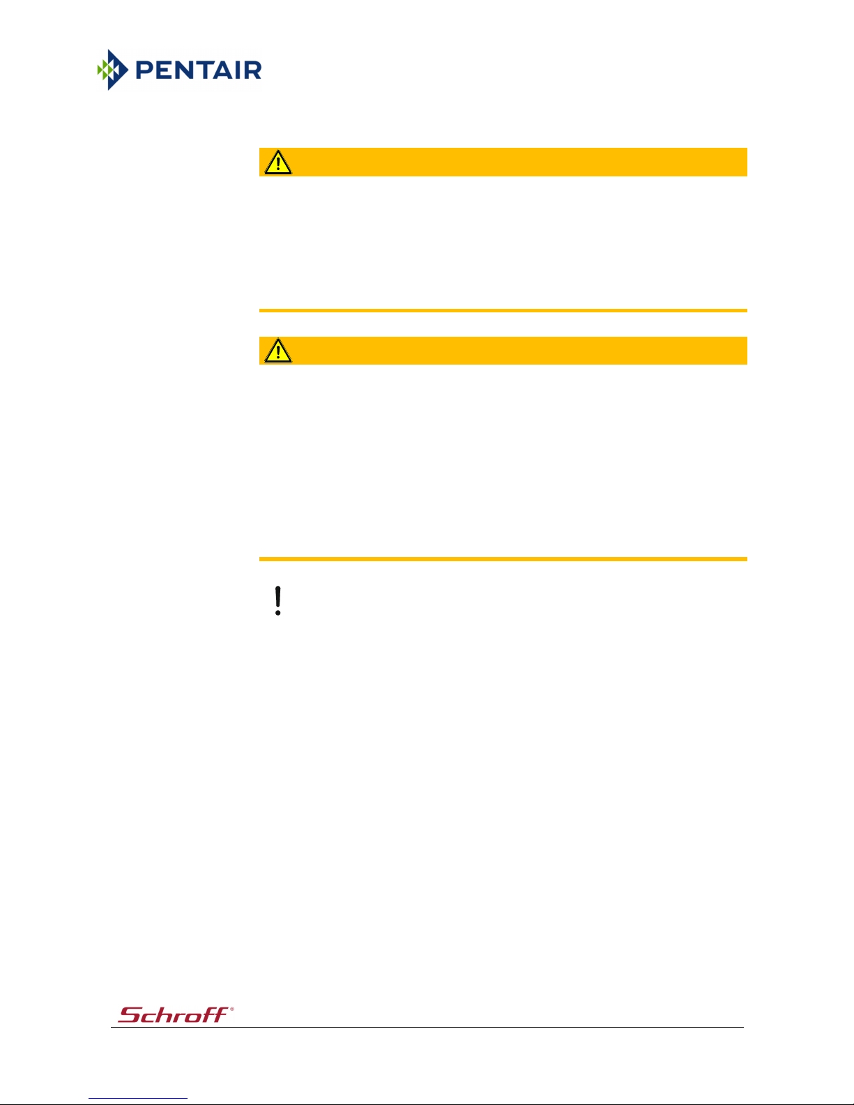
2.3 Mode of operation
Fig. 1: Mode of operation of the cooling module (principle)
1 Cooling module
2 External recooler *)
3 Pump *)
4 Enclosure
*) (not included in the scope of supply)
The cooling units are positioned between the VARISTAR cabinets in an enclosure.
The fans of the cooling unit suck the warm air in at the back and guide it through an
air/water heat exchanger. The air will be cooled and blown out at the front.
The cooling system comprises an air circuit and a water circuit. In the air/water heat
exchanger, the thermal energy of the warm air is transferred to the water.
The air/water heat exchanger is connected to an external recooler (not included in the
scope of supply) that cools the heated water.
12366
1 2
3
4
4
Page 14

VARISTAR Cooling unit SHX 30
Description / Overview 14
2.4 Air circuit
Example "cold aisle containment":
The fans of the cooling unit withdraw the heated air from the room and guide it through
an air/water heat exchanger. During this process, the thermal energy is transferred to the
water circuit. The cool air then fed into the cold aisle. A demister removes any condensate
that may have formed.
The condensate is collected in a condensate tray and discharged via the condensate pipe
at the top or bottom of the cooling module.
The fans that are distributed vertically over the entire cabinet height ensure a
homogeneous temperature stratification. As a result, the temperature difference can be
reduced and the efficiency of the cooling system can be increased.
Components of the air circuit:
• Air/water heat exchanger
• Demister
• Fans
• Temperature sensor (air)
2.5 Water circuit
The chilling medium of the external recooler (not included in the scope of supply) flows
through the air/water heat exchanger of the cooling modules and heats up. Then, it flows
back into the recooler. The temperature is controlled via an electric powered control valve
that controls the chilling medium flow based on the required cooling power.
Components of the water circuit:
• Control valve
• Air/water heat exchanger
• Water temperature sensor
Note
• The control valve in the water circuit of the cooling module is a straight-way valve
(2-way valve). The advantage of this solution is that only the quantity of water that
is required for cooling flows through the air/water heat exchanger. The circulation
pump can be operated with constant pressure and a variable quantity of water.
• For cooling systems that required three-way functionality, the cooling module can
also be supplied with a 3-way valve upon request.
Page 15

VARISTAR Cooling unit SHX 30
Description / Overview 15
2.6 Control method
The fans and the control valve of the water circuit are actuated by a closed loop and open
loop control unit. A closed loop control circuit controls the flow of water through the
air/water heat exchanger as a function of the air outlet temperature of the cooling
module.
The cooling module has four temperature sensors; two in the air outlet at the top and at
the bottom as well as two temperature sensors in the air inlet at the top and at the
bottom. In addition, an external temperature sensor (option) can be connected. The
output signal of these sensors is used as the reference value for the control system. The
reference sensor can be selected in the settings menu.
In order to compensate for temperature stratifications, the air outlet temperature is
measured by two temperature sensor on different levels. The average value of these
temperature sensors is the control variable for the opening characteristics of the control
valve.
Under normal operating conditions, the fans run at constant speed.
In order to ensure sufficient air circulation in the cabinet, the factory setting is 80% of the
nominal speed. The operator can set this value within a range of 30% to 100% via the
settings menu.
If the set temperature is exceeded by 4°C (factory setting), the system will switch to
maximum cooling power, i.e. the control valve will open by 100% and the fan speed will be
increased to 100% of the nominal speed.
If the actual value falls below the set temperature by 3°C, the normal mode will be
resumed.
Note
The control characteristic is defined at the factory. However, it can be changed and
adapted by the service department of Schroff or by a licensed service partner.
Page 16

VARISTAR Cooling unit SHX 30
Description / Overview 16
2.7 Alarms
The electronic control system can detect various malfunctions (e.g. cable break of a
temperature sensor, temperatures exceeding the limit values) and indicate them via the
display or interface.
In order to issue a visual alarm, there is an LED (red) above the control unit on the cooling
module.
The following error messages will be signalled:
• The actual fan speed is below the minimum speed.
• Failure of a fan.
• Cable break of a temperature sensor.
• Supply voltage of the electronic control system: undervoltage.
• Faulty Modbus communication.
• Failure of power supply unit 1 or 2.
• The actual cooling water temperature is above the limit value.
• Malfunction of the condensate pump (option).
• Door opened (option)
Note
In the event of a malfunction, refer to the "Troubleshooting" section.
Pos:23.3.1/Überschri ften/1.1/Ni cht bestim mungsgemäße Ver wendung @ 1 29\mod_133 7086719004_18. docx @ 1332 999 @ 2 @ 1
2.8 Incorrect use
Pos:23.3.2/Beschreib ung/Besti mmungswidrig e Verwendung /01-!! Grundsätzliches@ 129\m od_1337086111 550_18.d ocx @ 1332898 @@ 1
In general:
any incorrect use is classed as 'not for the intended purpose'. The manufacturer cannot be
held liable for any damage resulting from such use. The risk of such misuse lies entirely
with the user. Moreover, intended use of the unit also involves use in accordance with the
applicable international and national safety instructions as well as the safety instructions
in the manual.
Pos:23.4/Beschreib ung/Bestimmu ngswidrige Ver wendung /02 -DasGerä t ist unter and erem für folg ende Verw endungen NICH T vorgesehen: @ 129\mod_1337086308723_18.do cx @ 1332932 @ @1
Amongst others, the unit is NOT intended for the following applications:
Pos:23.5/Beschreib ung/Bestimmu ngswidrige Ver wendung /Betr ieb im Fr eien @ 154\ mod_13693179 83819_18.docx @ 1571962@ @1
• Outdoor use.
Pos:23.6/Beschreib ung/Bestimmu ngswidrige Ver wendung Betriebbeiei nem Überschreit en der zulä ssigen te chnischen Daten. Sieh e Kapitel "Te chnische Dat en". @ 18 8\mod_13951 27649326_18.d ocx @ 188429 3 @ @1
• Non-compliance with the permissible technical data. See the "Technical data"
section.
Pos:24/-- leer --/=== ===== @ 1\m od26_18.do cx @ 27188 @ @1
Page 17
VARISTAR Cooling unit SHX 30
Description / Overview 17
Pos:25/-- leer --/Sym bol -Weiterblät tern- @ 15\ mod_110303 6522860_18.do cx @ 125116 @ @1
Pos:26/-- leer --/=== ===== @ 1\m od26_18.do cx @ 27188 @ @1
Page 18
VARISTAR Cooling unit SHX 30
System Layout 18
Pos:27.1/Überschrifte n/1/Gerätea ufbau @ 1\m od6_18.docx @ 28614@ 1 @ 1
3 System Layout
Pos:27.2/Überschrifte n/1.1/Darstel lung @ 14\ mod5193_18. docx @ 28729 @2@ 1
3.1 Overview
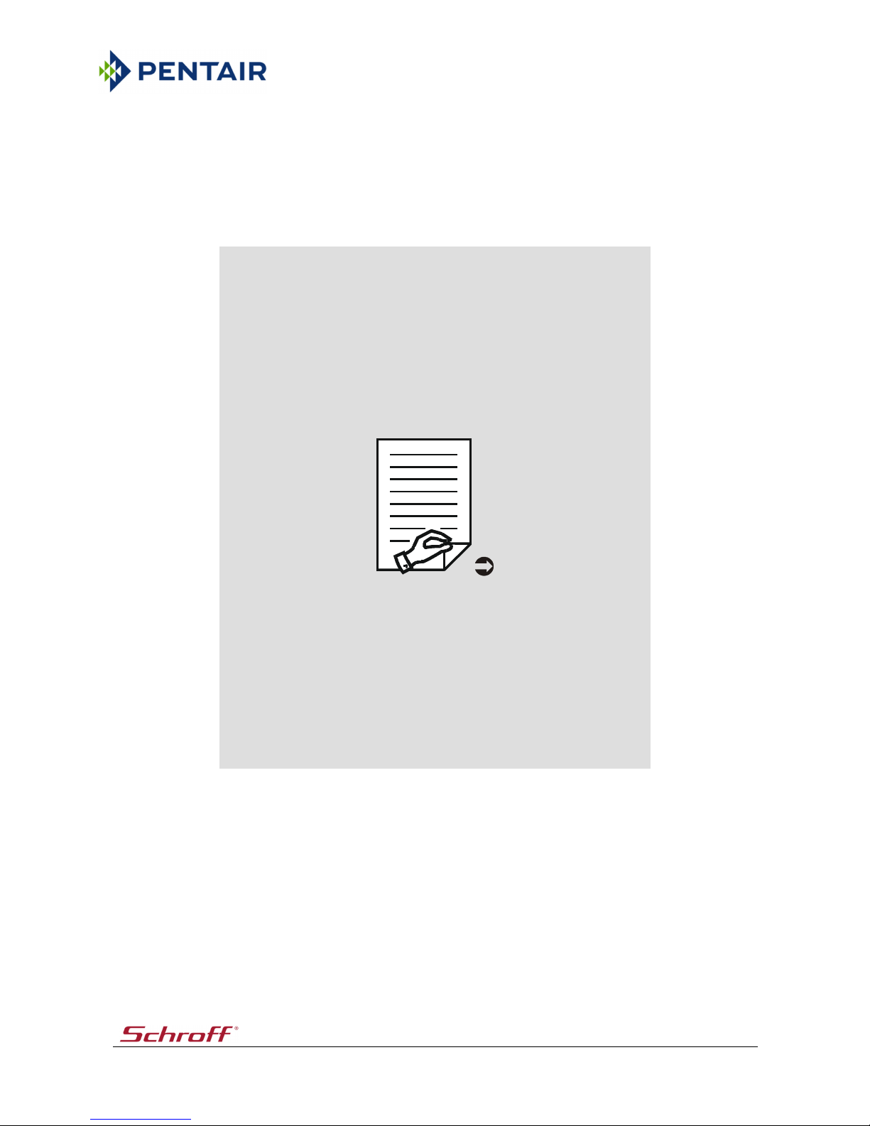
Pos:27.3/Gerateaufba u/Termotek/ Kühler SHX 30/DarstellungIM/SM @ 2 43\mod_142 296224166 4_18.docx @ 2236 200 @ @1
Fig. 2: Heat exchanger
12299-01
4
2
9
A
B
3
6
5
7
8
10
1
R2
R3
R5
R4
R1
Page 19

VARISTAR Cooling unit SHX 30
System Layout 19
1 Control valve with actuator
2 Power supply unit
3 Heat exchanger (air/water)
4 Switch box
5 Condensate pump with float switch (option)
6 Condensate tray
7 Demister
8 Fan
9 Control unit (display and operating unit)
10 LED (red)
- flashing: malfunction *)
Views
A Front view
B Back view
Temperature sensor
R1 Chilling medium inlet
R2 Air inlet (top)
R3 Air inlet (bottom)
R4 Air outlet (top)
R5 Air outlet (bottom)
Note
*) In the event of a malfunction, refer to the "Troubleshooting" section.
Pos:27.4/-- leer --/= ======= @ 1\ mod26_18.do cx @ 27188 @ @1
Page 20
VARISTAR Cooling unit SHX 30
System Layout 20
Pos:27.5/Überschrifte n/1.1/Ans chlüsse @ 15\m od_110378697 9042_18.d ocx @ 126968 @2@ 1
3.2 Connections
Pos:27.6/Gerateaufba u/Termotek/ Kühler SHX 30/Anschlüsse@ 243\m od_14229624388 46_18.do cx @ 2236274 @@ 1
Fig. 3: Connections
12299-01
Y
X
1 2 3
6
“X“
1 2 3
4
5
Page 21

VARISTAR Cooling unit SHX 30
System Layout 21
1 Condensate outlet
2 Chilling medium outlet
3 Chilling medium inlet
4 Venting point
5 Protective earth
6 Power supply connector (redundant power
supply)
X Connectors (top)
Y Connectors (bottom)
Note
• The chilling medium connectors are located at the top and bottom of the unit
(back). Connectors that are not required must be sealed with a blind plug.
• In the case of cooling modules with a water connection at the top, the condensate
outlet is also located at the top. These cooling modules are equipped with an
integrated condensate pump.
• Connect the condensate outlet with a sufficient gradient to the wastewater
system.
• Cooling modules with a redundant power supply are equipped with two power
supply units and mains power inputs. They can be supplied with power via two
independent mains power sources.
Pos:27.7/-- leer --/= ======= @ 1\ mod26_18.do cx @ 27188 @ @1
Page 22
VARISTAR Cooling unit SHX 30
System Layout 22
Pos:27.8/Überschrifte n/1.1/Schaltka sten @ 156\ mod_137223 0752978_1 8.docx @ 1589287 @2@ 1
3.3 Electrical box
Pos:27.9/Gerateaufba u/Termotek/ Kühler SHX 30/Schaltkasten@ 242\ mod_14229563 80558_18.d ocx @ 22348 54 @ @1
Fig. 4: Electrical box
1 Fuse board (circuit board with miniature fuses)
2 Basic electronic system, type TIOM 112 (I/O unit)
3 Power supply connector (optionally with a
second power supply unit)
4 Interlock-interface (DI/DO, 10 pin)
5 Data interface (RS232, SUB-D, 6 pin)
6 Data interface (RS485, 2x RJ45)
7 Connector for connecting the external
temperature sensor
8 Interface board
Pos:27.10/Hinweise/All gemeinHi nweis - Stro mlaufplan beac hten @ 174\ mod_13855439 96932_18.doc x@ 1767106@ @1
Note
Follow the instructions given in the circuit diagram.
Pos:27.11/-- leer --/== ====== @ 1\ mod26_18.d ocx @ 27188 @@ 1
12300-01
3
5
6
7
1
2
8
4
Page 23
VARISTAR Cooling unit SHX 30
System Layout 23
Pos:27.12/Überschrifte n/1.1/Syst emschema @14\mod5130_18.docx @ 2 8752 @ 2 @ 1
3.4 Schematic system diagram
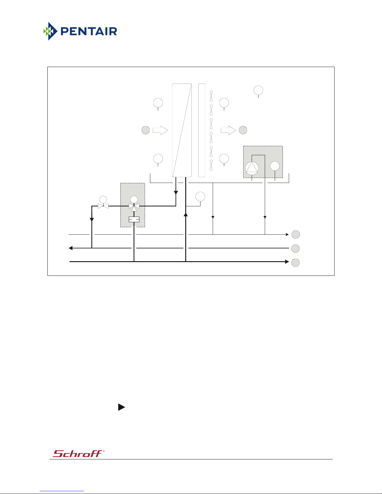
Pos:27.13/Gerateauf bau/Termotek/ Kühler SHX 30/S ystemsche ma @ 152\m od_136618942 1554_18.d ocx @ 153772 8 @ @1
Fig. 5: Schematic system diagram
1 Heat exchanger (air/water)
2 Demister
3 Fan
4 Condensate pump with float switch (option)
5 Condensate tray
6 Control valve (two-way valve) with actuator
7 Control valve (three-way valve) with actuator
(option)
8 Orifice plate (option)
9 External temperature sensor (option.
Connection: customer-specific)
A Air flow (inlet, outlet)
Connectors
B Condensate outlet
C Chilling medium outlet
D Chilling medium inlet
Temperature sensors
R1 Chilling medium inlet
R2 Air inlet (top)
R3 Air inlet (bottom)
R4 Air outlet (top)
R5 Air outlet (bottom)
Pos:27.14/Hinweise/All gemeinHi nweis - Stro mlaufplan beac hten @ 174\ mod_13855439 96932_18.doc x@ 1767106@ @1
Note
Follow the instructions given in the circuit diagram.
Pos:27.15/-- leer --/== ====== @ 1\ mod26_18.d ocx @ 27188 @@ 1
12316
TCTC
TCTC
TCTCLC
123
R2
R3
R4
R5
R1
5
7
8
A
ABC946D
Page 24

VARISTAR Cooling unit SHX 30
System Layout 24
Pos:27.16/Gerateauf bau/Termotek/ Kühler SHX 30/1 .1 Funktio nsübersicht @242\mod_1422956485 872_18.d ocx @ 2234888 @2@ 1
3.5 Function overview
Fig. 6: Function overview (principle)
1 Control unit (display and operating unit)
2 Basic electronic system (I/O unit)
3 Interface board
4 Fuse board (circuit board with miniature fuses)
5 Temperature sensor (internal)
6 Temperature sensor (external)
7 Control valve
8 Condensate pump
9 Terminating resistor
10 Float switch
11 Fan
Pos:27.17/Hinweise/All gemeinHi nweis - Stro mlaufplan beac hten @ 174\ mod_13855439 96932_18.doc x@ 1767106@ @1
Note
Follow the instructions given in the circuit diagram.
Pos:27.18/-- leer --/== ====== @ 1\ mod26_18.d ocx @ 27188 @@ 1
12356-01
X2
X11X11
X10
X9 X8 X7 X6 X5
X13
X12
X14
X4X3X2X1
12345678OFF
ON
X1X2X3X4X5X6X7
X0
XG4
RS232
(SUB-D, 6 pol.)
RS485
RJ45
RS485
RJ45
R
X8
X9
X10
1
234
5
6
7810
11
9
LC
TC
Interlocks
TC
TC
TC
TC
TC
Page 25

VARISTAR Cooling unit SHX 30
System Layout 25
Pos:27.19/Überschrifte n/1.1/Sc hilder / Symbole a m Gerät @ 80\ mod_12 66232817346_18. docx @ 8799 17 @ 2 @ 1
3.6 Symbols / labels on the unit
Pos:27.20/Gerateauf bau/Termotek/ Kühler SHX 30/S childer a m Gerät @ 24 3\mod_1423 119597319_18.d ocx @ 22375 01 @ @1
Fig. 7: Labels on the unit
Label Description
1 Bar code
2 Chilling medium outlet
3 Venting point
4 Chilling medium inlet
5 Information concerning the interface (RS232, RS485) and
connection of the external temperature sensor
6 Connection point for I/O signal
• Interlock-interface (DI/DO, 10 pin)
7 Power supply connector (redundant power supply)
A Connector 1
B Connector 2 (redundant)
8 Type plate of the unit
Pos:28/-- leer --/=== ===== @ 1\m od26_18.do cx @ 27188 @ @1
12367-01
123
4824567
Bleeding
External
Temperature sensor
RS485RS232
INTERLOCKS
100-240V AC
50/60 Hz
B A
....
....
....
Page 26

VARISTAR Cooling unit SHX 30
Components 26
Pos:29.1/Überschrifte n/1/Kompo nenten @ 1\ mod7_18.doc x @ 32547 @ 1 @1
4 Components
Pos:29.2/Überschrifte n/1.1/Regelve ntil @ 20\ mod_11326533 21810_18. docx@ 245690@ 2 @ 1
4.1 Control valve
Pos:29.3/Komponenten /Regelventil/Sa uter/AV M105 - Allge mein @ 243\ mod_1422962 588574_18.do cx @ 2236308 @ @1
Control valve for the continuous control of cooling media in loops.
Fig. 8: Actuator, control valve (Example)
1 Actuator
2 Control valve
3 Display for opening degree of control valve (0-
100%)
4 Adjusting screw of actuator
5 Cover cap of DIP switch
6 Valve spindle
7 Locking mechanism (engaging)
8 Selector switch (Automatic / Manual)
9 Connection cable
The actuator is directly plugged onto the control valve and fixed with a nut. The
connection of the drive with the valve spindle is done automatically.
The valve is closed with the valve spindle pulled out.
Note
• The drive will move out during the first commissioning of the plant. The cap closes
automatically when reaching the lower valve seat. The stroke of the valve is
detected by the drive.
• The DIP switch is set ex works. Setting: see circuit diagram.
Pos:29.4/-- leer --/= ======= @ 1\ mod26_18.do cx @ 27188 @ @1
12430
0
%
1
0
0
%
"X"
X
auto
man
123789456
Page 27

VARISTAR Cooling unit SHX 30
Components 27
Pos:29.5/Überschrifte n/1.1/Gerätest euerung @ 15\mod_1106550857781_18.docx @ 134733@2 @1
4.2 Control unit
Pos:29.6/Komponenten /Modulgrup pen/Term otek/Text - Gerät esteuerung @ 1 56\mod_137 215431688 3_18.docx @1588585@ @1
Adjustments and adaptations concerning the cooling module can be performed via the
control unit (display and operating unit). Under normal operating conditions, the display
unit displays the actual value of the selected temperature sensor. The control unit is
located at the front of the cooling module.
Apart from four membrane keys and display with 2 x 20 digits, the display and operating
unit also includes the entire electronic control system. The electronic control system is
connected to a remote I/O unit (basic electronic system) at the back of the cooling module
via a CAN bus.
Pos:29.7/Komponenten /Gerätesteu erung/TRE 02 2/112/Bedient asten, Display (TRE-022)- Fa. Schr off @ 156\ mod_13721535 58752_18.doc x@ 1588399@ @1
Fig. 9: Control unit (front view)
1 Confirmation key (Enter key)
2 Cancel key (ESC key)/backward key
3 Selection and setting key (down key)
4 Selection and setting key (up key)
5 Display
Pos:29.8/Komponenten /Gerätesteu erung/TRE 02 2/112/Ans chlüsse (TRE -022) @ 39\mod_1 181905266 127_18.doc x@ 47 5517 @ @1
Fig. 10: Control unit (connections)
1 CAN interface - digital inputs / outputs (option)
2 Power supply
3 RS232/485 jack
Pos:29.9/-- leer --/= ======= @ 1\ mod26_18.do cx @ 27188 @ @1
12302
1
2
3
4
5
D4096G007
1 2 3
Page 28

VARISTAR Cooling unit SHX 30
Components 28
Pos:29.10/Komponente n/Modulgru ppen/Term otek/1.1 SH X 30 -I nterfa ceboard - Schnittst elle (RS232, RS485(RJ45)) @ 242\m od_1422956838 259_18.do cx @ 2234958 @2@ 1
4.3 Interface board
Fig. 11: Interface board
The interface board is a device interface and used for the connection of an external
temperature sensor (1).
RS485:
The RS485 data interface (2x RJ45, female connector) is used for the communication
between the cooling module and an external monitoring module via the Modbus protocol.
Pin Name
4 B
5 A
6 GND
12358-01
Interlocks
1 8 1 8
RS485
(RJ45)
RS232
(SUB-D, 6 pol.)
1
Page 29

VARISTAR Cooling unit SHX 30
Components 29
RS232, 6 pin:
The RS232 data interface (SUB-D, male connector) is used for the communication between
the cooling module and an external monitoring module via the Modbus protocol. For
service purposes, the interface is used for the firmware update of the control system.
Pin Name
2 TxD
3 RxD
4 GND
Interlock, DI/DO, 10 pin:
The Interlock-interface serves to connect the door contact switch and as an output for 4
freely programmable fault relays.
Pin Name
1 TK.1
2 TK.2
3 Out1.1
4 Out1.2
5 Out2.1
6 Out2.2
7 Out3.1
8 Out3.2
9 Out4.1
10 Out4.2
Pos:29.11/-- leer --/== ====== @ 1\ mod26_18.d ocx @ 27188 @@ 1
Page 30

VARISTAR Cooling unit SHX 30
Components 30
Pos:29.12/Komponente n/Modulgru ppen/Term otek/1.1 LHX 3 0 - Fuse-Board @156\mod_137225 1869402_18.do cx @ 1589762 @2@ 1
4.4 Fuse board
The fuse board is a circuit board that is equipped with miniature fuses and used for the
actuation and protection of the fans.
The fans are actuated via the control unit and I/O unit (basic electronic system).
The power supply of the fuse board is ensured by power supply units.
In the event of a failure of the fans, it may be necessary to check and replace the
miniature fuses.
Fig. 12: Fuse board
Miniature fuse Connector Fan
F1 X2 1
F2 X3 2
F3 X4 3
F4 X5 4
F5 X6 5
F6 X7 6
F7 X8 7 (option)
Pos:29.13/Hinweise/All gemeinHi nweis - Stro mlaufplan beac hten @ 174\ mod_13855439 96932_18.doc x@ 1767106@ @1
Note
Follow the instructions given in the circuit diagram.
Pos:29.14/-- leer --/== ====== @ 1\ mod26_18.d ocx @ 27188 @@ 1
12359
X1X2X3
X4X5
X6
X7
X8
X9
X10
X11
X13 X12 X17 X18 X16
X15
F9
F8
F10
F11
F7
F6
F5
F4
F3
F2
F1
Page 31

VARISTAR Cooling unit SHX 30
Components 31
Pos:29.15/Überschrifte n/1.1/Basi selektronik @ 1 5\mod_11077 60990524_ 18.docx @ 1 38873 @ 2 @ 1
4.5 Basic electronic system
Pos:29.16/Komponente n/Geräteste uerung/Basis elektronik_Kart en (Beieiner Versionier ung ergänz en: DIP-Schalt er (Einstellung sie he SLP)/TI OM/-112 fürIM@ 154\ mod_1368538 265582_18. docx @ 1566 308 @ @1
Fig. 13: Basic electronic system (example)
1 DIP switch (see the circuit diagram for setting information)
2 Pilot LED (CPU-K): LED flashes = processor active
3 Pilot LED (+24V-T): 24 V active on connector X13, X14
4 Pilot LED (RUN/ERR): CAN communication
- LED lights green = normal state
- LED lights red = communication problem
5 Jumper +24V - T
6 Jumper 0V - T
Connector Description
X1 Digital inputs
X2 Digital inputs
X3 Digital outputs
X4 Power supply
X5 Digital outputs
X6 Analogue outputs
X7 Analogue outputs
X8 Analogue inputs
X9 Analogue inputs
X10 Analogue inputs
X11 Analogue inputs
X12 Analogue inputs
X13, X14 CAN bus
Pos:30/-- leer --/=== ===== @ 1\m od26_18.do cx @ 27188 @ @1
12317
12345678OFF
ON
X12 X11 X10 X9 X8 X7 X6 X5
2
X13
X14
3
4
5
6
X1 X2 X3 X4
1
Page 32

VARISTAR Cooling unit SHX 30
Setting Up 32
Pos:31.1/Überschrifte n/1/Inbetrieb nahme @ 1 \mod8_18.d ocx @ 32593 @1@ 1
5 Setting Up
Pos:31.2/Überschrifte n/1.1Allge mein @ 15\ mod_110655320021 8_18.do cx@ 135193@ 2 @ 1
5.1 General information
Pos:31.3/Hinweise/War nung Perso nenWarnung -Kippgefahr (schmales Gerät)@1 90\mod_1396 607317081 _18.docx @ 1904739@ @ 1
WARNING
Danger of overturning!
Due to the slim set-up of the unit, there is a higher risk of injury when the unit tips over.
Ensure that the unit is sufficiently secured during the transport.
Pos:31.4/Hinweise/Vorsi cht / Ac htung - GerätA chtung - Schwit zwasser bei Tem.<15°C @ 190\mo d_13966074939 77_18.docx @1904807 @ @1
Notice
Danger of damage due to condensation!
At temperatures below 15°C/59°F, condensation may form inside the unit and cause
damage to the unit when it is switched on.
Prior to switching the unit on, ensure that the unit has acclimatised sufficiently.
Pos:31.5/Hinweise/Vorsi cht / Ac htung - GerätA chtung - Bes chädigung dur chS chmutzpartik el, Install . reinigen/spüle n @ 166\mod_1 381309051 871_18.doc x@ 16 60704 @ @1
Notice
Damage through dirt particles!
Dirt particles in customer-provided installations (e.g. pipes, hoses, ...) may lead to
malfunctions or damage to the components or unit/system.
• Ensure that the customer-provided installations (e.g. pipes, hoses, ...) are free
from dirt particles.
• If necessary, clean, rinse, or flush the customer-provided installations.
Pos:31.6/Hinweise/Vorsi cht / Ac htung - GerätA chtung - Ausfließ endes Medi um @ 190\ mod_139660 7422781_18.do cx @ 1904773 @@ 1
Notice
Risk of damage to components!
The medium that is to be connected (e.g. cooling water) can cause damage.
• Take suitable measures (e.g. leak sensors, automatic shut-off valves) in order to
prevent damage to the neighbouring components in the event of a leak or defect.
• These measures depend on the installation site and the building-relate conditions
on site. They are in the area of responsibility of the fitter or system planner.
Pos:31.7/-- leer --/= ======= @ 1\ mod26_18.do cx @ 27188 @ @1
Page 33

VARISTAR Cooling unit SHX 30
Setting Up 33
Pos:31.8/Inbetriebna hme - Montag eHinweis - O ptimale Wasserq ualität z.Befüllung: s.Kap."TD" - ( ohne Rohrtrenn er) @ 181\ mod_13896011 70371_18. docx @ 1840863 @ @1
Note
Optimum water quality for filling: information can be found in the “Technical Data”
section.
Pos:31.9/Inbetriebna hme - Montag e/MontageHinwei s - Au fstellen, Inbetrieb nahme, Ko mplettierung, War tung ... der Ger äte durc h Fachperso nal @ 190\mod_1 396609490 554_18.doc x@ 19 04841 @ @1
Note
• Only trained, specialised personnel is authorised to perform the set-up, start-up,
completion, maintenance, and service of the units.
• Observe the "Safety" section.
• Comply with the national rules and regulations concerning occupational health
and safety.
Pos:31.10/Inbetrieb nahme - Montag e/MontageHinwei s - Lag erung oder Trans port bei <0° C, Verweis a ufFr ostschutz... @190\mod_13966 09639905_18.d ocx @ 1904875 @@ 1
Note
The storage or transport at ambient temperatures below 0°C/32°F require special
measures in order to avoid frost damage.
• Observe the "Anti-freeze and corrosion protection" section.
• Transport the unit only without water.
Pos:31.11/Inbetrieb nahme - Montag eVerweis - WeitereInformatione n aufv ersch. Kapit el @ 30\m od_1161080564 982_18.d ocx @ 362557 @@ 1
For further information regarding connections, versions, pressure specifications, settings
etc. please refer to the following chapters:
• Layout / System layout
• Components
• Maintenance
• Technical Data
as well as the instruction labels on the unit (if provided).
Pos:31.12/-- leer --/== ====== @ 1\ mod26_18.d ocx @ 27188 @@ 1
Page 34

VARISTAR Cooling unit SHX 30
Setting Up 34
Pos:31.13/Überschrifte n/1.1/Trans port- und Verpa ckungsmateria l @ 18\ mod_11225445 39707_18.doc x@ 197743@ 2 @ 1
5.2 Transport and packaging material
Pos:31.14/Inbetrieb nahme - Montag e/Termotek/Te xt - Das Ger ät wird auf ei ner Sonderpalet te angelie fert. @ 156\m od_137206736 2377_18.d ocx @ 158754 3 @ @1
The unit will be delivered on a special pallet.
Pos:31.15/Inbetrieb nahme - Montag e/Transp ort von GerätenTran sport- un d Verpackungs material entfer nen. @ 15\ mod_11062346 11097_18. docx @ 1324 56 @ @1
Remove any transport material and packaging.
Pos:31.16/Inbetrieb nahme - Montag e/Transp ort von GerätenTran sport- un d Verpackungs material entsorg en @ 81\ mod_126779 2765671_18.do cx @ 891391 @ @1
Dispose of the transport and packaging material in an environmentally-compliant manner
and in accordance with the applicable local rules and regulations.
Pos:31.17/Hinweise/All gemeinHi nweis - Gerät nachAuspacken auf Trans portschäde n ... prüfen. @ 18 1\mod_1389 359794718_ 18.docx @ 1 840284 @ @1
Note
After unpacking, check the unit for signs of transport damage or other damage.
Pos:31.18/Hinweise/All gemeinHi nweis - Transp ortbeschädig ungen bei eventuell en Rückt ransport @ 190 \mod_13966 09731059_ 18.docx @ 19 04909 @ @1
Note
In order to avoid transport damage if the unit needs to be returned to the manufacturer,
return the unit solely in its original packaging.
Pos:31.19/Überschrifte n/1.1/Erstinb etriebna hme @ 156\mo d_13722350610 91_18.doc x @ 1589365 @2@ 1
5.3 Start-up
Pos:31.20/Hinweise/Elekt ro (Ge fahr, Warnung, Vor sicht)Ge fahr -E -Anschlü sse - Arbeiten a mg eöffnete n Gehäuse @190\mod_13960040470 08_18.docx @1897564 @ @1
DANGER
Electrical hazard!
It may be necessary to open the housing in order to perform work on the unit. Exposed
parts may be energised and cause an electric shock if they are touched.
Observe the following points when working on the electrical system:
• Observe the "Safety" section.
• Ensure that the tasks are performed solely by qualified experts.
1. Disconnect the unit from the power supply in order to deenergise it.
2. Secure the unit so that it cannot be switched on again accidentally.
3. Check whether the unit is properly disconnected from power and absolutely
voltage-free
4. Earth and short-circuit the unit.
5. Cover any adjacent live parts and secure the danger area.
Pos:31.21/Inbetrieb nahme - Montag e/Termotek/SH X30Erstin betriebnahm e @ 242\mod_ 142295900 8583_18.doc x@ 22 35520 @ @1
Prior to the start-up, the following tasks must be performed:
• Set the unit up.
• Connect the cooling water supply.
• Connect the power supply.
• Vent the unit.
Note
The set-up, start-up, maintenance, and service should be performed by the after-sales
service. If necessary, contact the after-sales service (see the "Contact addresses" section).
Pos:31.22/-- leer --/== ====== @ 1\ mod26_18.d ocx @ 27188 @@ 1
Page 35

VARISTAR Cooling unit SHX 30
Setting Up 35
Pos:31.23/Überschrifte n/1.1/Au fstellung @ 16\ mod_11080417 23954_18. docx @ 1409 65 @ 2 @ 1
5.4 Installation
Pos:31.24/Hinweise/All gemeinHi nweis - Kapitel "Sicherheit/ Standort wahl" - zur Auf stellung @ 166\ mod_1381309 999715_18. docx @ 1660 909 @ @1
Note
Comply with the instructions that are given in the "Safety/Selecting the installation site"
section.
Pos:31.25/Inbetrieb nahme - Montag e/Aufstellu ng/Text - Maxi male Längen Kap."TD". Anschlüsse z. G erät flexi bel, ausr. Druck festigk., Tem p.bestä @ 149\ mod_136266 3872876_1 8.docx @ 1518930 @@ 1
Comply with the maximum lengths (hoses, pipes, cables etc.) and pressure and
temperature values as stated in the "Technical Data" section.
The connections to the unit must be flexible and sufficiently pressure- and temperatureproof.
Pos:31.26/Überschrifte n/1.1/Ans chlüsse @ 15\ mod_11037869 79042_18. docx @ 12696 8 @ 2 @ 1
5.5 Connections
Pos:31.27/Inbetrieb nahme - Montag e/Anschlüsse /Mechanis ch/GlykolAchtu ng - Geschl. A bspvl im C-Krei s - unzul. Tem p. @ 190\ mod_13966105 61888_18. docx @ 1905103 @ @1
Notice
Risk of damage to components!
Closed shut-off devices in the chilling medium circuit lead to impermissible temperatures,
thereby causing the unit to be switched off, or they can damage the unit.
Ensure that the shut-off devices inside the unit and on site are open prior to starting the
unit.
Pos:31.28/Hinweise/All gemein/Hi nweis - Kühlme dium-Anschl uss (Anforder ungen) @ 1 53\mod_13669590 10415_18. docx @ 15577 63 @ @1
Notes concerning the chilling medium connection
• The customer-provided chilling infrastructure (external water circuit) must be
dimensioned by the system planner while taking into consideration the available
pump pressure, pump design, nominal pipe widths, and the expected pressure
losses in the consumer circuit (cooling modules).
• Keep the pipes (chilling medium) as short as possible in order to avoid pressure
losses in the system.
• The chilling medium pipes can be either fixed or flexible. The compatibility of the
materials in the cooling modules with the materials of the external system circuit
must be taken into consideration in order to avoid damage due to corrosion.
• When installing the customer-provided pipes, contamination of the pipes must be
absolutely avoided. Flush the pipes prior to connecting the cooling module.
• We recommend installing customer-provided shut-off and drain valves on every
cabinet or cooling module as well as using a central water filter and air separator.
Pos:31.29/Inbetrieb nahme - Montag e/Anschlüsse /Mechanis ch/All. Beschreib. : Verbindunge n zum Gerät vornehmen.@ 17\m od_111409461 5493_18.doc x @ 172408 @@ 1
Connect the unit.
Pos:31.30/-- leer --/......... .... Absatz ... ......... @ 77\ mod_1262789 107248_0. docx @ 85546 8 @ @1
Pos:31.31/Inbetrieb nahme - Montag e/Anschlüsse /Mechanis chHinweis -Anschlussgrößen gemäß Kapit el "TD" @ 17 0\mod_1382 684229585 _18.docx @ 1 706335 @ @1
Note
Connection sizes according to the "Technical Data" section
Pos:31.32/-- leer --/== ====== @ 1\ mod26_18.d ocx @ 27188 @@ 1
Page 36

VARISTAR Cooling unit SHX 30
Setting Up 36
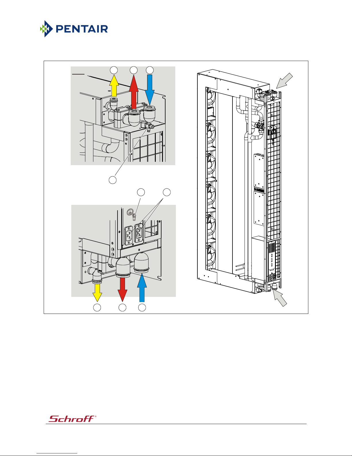
Pos:31.33/Inbetrieb nahme - Montag e/Termotek/SH X30/Ansc hlüsse @ 243 \mod_14229 62702531_18.d ocx @ 223634 2 @ @1
Note
• Depending on the variant, the connectors and the condensate outlet are located
at the top or bottom of the cooling module. The pipes are fed in/out through the
bottom or top of the unit cabinet.
• Connectors that are not required must be sealed with blind plugs.
Fig. 14: Chilling medium connectors
X Connectors (top)
Y Connectors (bottom)
1 Condensate outlet
2 Chilling medium outlet
3 Chilling medium inlet
• Connect the chilling medium inlet.
• Connect the chilling medium outlet.
• Connect the condensate outlet with a sufficient gradient to the wastewater system.
Pos:31.34/-- leer --/== ====== @ 1\ mod26_18.d ocx @ 27188 @@ 1
12305-01
X
Y
“X“
1
2
3
“Y“
123
Page 37

VARISTAR Cooling unit SHX 30
Setting Up 37
Pos:31.35/Überschrifte n/1.1/Elekt rischer Ansc hluss @ 16\m od_1108040151 943_18.doc x @ 140896 @ 2@1
5.6 Electrical connection
Pos:31.36/Hinweise/Elekt ro (Ge fahr, Warnung, Vor sicht)Ge fahr - Lebensge fahr bei Anschl uss falscher A nschlusss pannung @ 181\ mod_13893615 45475_18. docx @ 1840 476 @ @1
DANGER
Danger to life due to electrical hazard!
There is a risk of death by electric shock if the connected voltages are not correct.
• Only qualified and specialised personnel is authorised to perform the connection.
• Compare the connection voltage to the voltage that is stated on the type plate.
• Comply with the specifications of the circuit diagram.
Pos:31.37/Hinweise/Elekt ro (Ge fahr, Warnung, Vor sicht)Ge fahr -E -Anschlü sse - Arbeiten a mg eöffnete n Gehäuse @190\mod_13960040470 08_18.docx @1897564 @ @1
DANGER
Electrical hazard!
It may be necessary to open the housing in order to perform work on the unit. Exposed
parts may be energised and cause an electric shock if they are touched.
Observe the following points when working on the electrical system:
• Observe the "Safety" section.
• Ensure that the tasks are performed solely by qualified experts.
1. Disconnect the unit from the power supply in order to deenergise it.
2. Secure the unit so that it cannot be switched on again accidentally.
3. Check whether the unit is properly disconnected from power and absolutely
voltage-free
4. Earth and short-circuit the unit.
5. Cover any adjacent live parts and secure the danger area.
Pos:31.38/Inbetrieb nahme - Montag e/Anschlüsse /ElektroAcht ung - Falsche An schlussspan nung @ 180\ mod_138864 9917441_1 8.docx @ 1831680 @@ 1
Notice
Wrong connected voltage!
Incorrect supply voltages can lead to component damage.
Compare the supply voltage value with the voltage specification stated on the nameplate.
Ensure the necessary fuse protection in accordance with the "Technical Data" section or
circuit diagram.
Pos:31.39/Inbetrieb nahme - Montag e/Termotek/Elek trische Ans chlüsse/Hinw eis - E-Ansc hluss @ 242 \mod_142295 9211225_18.do cx @ 2235622 @@ 1
Note
• Units with two mains power inputs are designed for the redundant power supply
via two independent mains power sources.
• The unit is supplied with operating voltage via an IEC320-C20 connector with cable
lock at the back of the unit.
• A corresponding connecting cable (IEC320-C19 - two-pin earthed connector) is
included in the scope of supply.
• The units must be protected by a series fuse in the building in accordance with the
"Technical data" section.
Pos:31.40/-- leer --/== ====== @ 1\ mod26_18.d ocx @ 27188 @@ 1
Page 38

VARISTAR Cooling unit SHX 30
Setting Up 38
Pos:31.41/Hinweise/All gemeinHi nweis - Stro mlaufplan beac hten @ 174\ mod_13855439 96932_18.doc x@ 1767106@ @1
Note
Follow the instructions given in the circuit diagram.
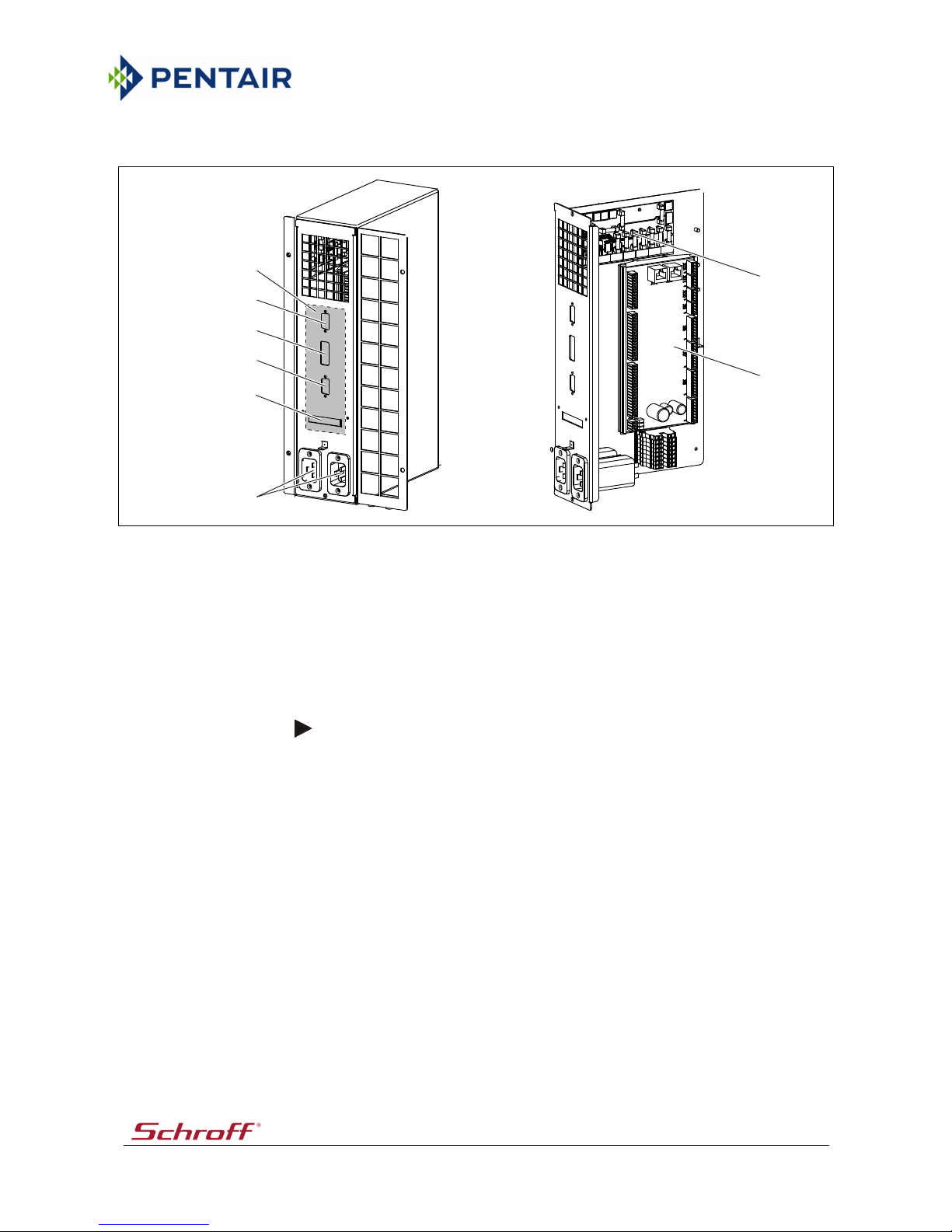
Pos:31.42/Inbetrieb nahme - Montag e/Termotek/SH X30/E-Ans chlüsse @ 242\ mod_1422957 897744_18 .docx @ 223 5136 @ @1
Fig. 15: Electrical connection
• If necessary, connect an interface cable for the device communication:
- Interlocks (DI/DO), 10 pin (2)
- RS232, 6 pin (3)
- 2x RJ45 (4)
• Connect the external temperature sensor (5) (depending on the customer
requirements).
• Connect the power supply (1).
• Observe the local rules and regulations.
• See the "Technical data" section.
Note
• In order to avoid communication problems, lay the interface cable (data line) and
the electrical power supply cables separate from each other.
• Once the operating voltage has been applied, the unit is in the standby mode.
Various components inside the unit are live.
• Disconnect the operating power supply prior to opening the unit.
• Once the operating voltage has been applied, the actuator of the control valve is
energised and performs an initialisation.
Pos:31.43/-- leer --/== ====== @ 1\ mod26_18.d ocx @ 27188 @@ 1
12305-01
X
“X“
54312
Page 39

VARISTAR Cooling unit SHX 30
Setting Up 39
Pos:31.44/Überschrifte n/1.1/Frost -, Korrosion sschutz @ 54\ mod_12072963 19973_18.do cx @ 608185 @ 2 @1
5.7 Antifreeze and anti-corrosion agents
Pos:31.45/Inbetrieb nahme - Montag e/Anschlüsse /Mechanis ch/T-Kreis/Glyk ol/Frost-, K orrosionssch utz/01a - Text: e xterne Rückk ühlanlage - Term otek (Kühl modul, ...) @ 153 \mod_13668 73150682_1 8.docx @ 15 56513 @ @1
If aluminium is used in the external water circuit, there is a risk of corrosion. In order to
avoid electrochemical corrosion, it must be checked whether the materials that are used
in the cooling module are compatible with the materials of the external cooling circuit.
The type and dose of a suitable anti-corrosion or anti-freeze agent depends on the
situation on site and also on the external re-cooling system. It must be determined by the
system planner.
The following materials are used in the cooling module.
• copper
• bras
• stainless steel
• gunmetal
Pos:31.46/Inbetrieb nahme - Montag e/Anschlüsse /Mechanis ch/T-Kreis/Glyk ol/Frost-, K orrosionssch utz/02 - Text: S chutz der Ba uteile KANN Syste mkreis be füllt sein @ 154\ mod_1368540 855491_18 .docx @ 156 6457 @ @1
In order to protect the components in the system circuit against corrosion and frost
damage, the system circuit must be filled with an anti-corrosion and anti-freeze agent.
Frost damage may be caused by contamination, air that is trapped inside the system, or by
a pump malfunction.
Pos:31.47/-- leer --/......... .... Absatz ... ......... @ 77\ mod_1262789 107248_0. docx @ 85546 8 @ @1
Pos:31.48/Inbetrieb nahme - Montag e/Anschlüsse /Mechanis ch/T-Kreis/Glyk ol/Frost-, K orrosionssch utz04 - Achtung-Hi nweis - Glykolk onzentra tion @ 174\ mod_13853838 84654_18.doc x@ 1 761828 @ @1
Notice
Damage to components
If the concentration of anti-corrosion or anti-freeze agents is too high or too low in the
circuit, components may be damaged (e.g. the seals). If the concentration is too low, the
corrosion may actually be stimulated.
When using anti-corrosion or antifreeze agents, please comply with the information
provided by the manufacturers concerning the area of application, the compatibility with
other materials, and the minimum/maximum mixing ratio, etc.
Pos:31.49/Inbetrieb nahme - Montag e/Anschlüsse /Mechanis ch/T-Kreis/Glyk ol/Frost-, K orrosionssch utz05.1 - Info BefüllungT-Kreis: Allge mein - alle @ 188 \mod_139513 8505119_1 8.docx @ 18 84657 @ @1
When using monoethylene glycol as the anti-corrosion and anti-freezing agent, please
observe the following points:
• Do not mix anti-corrosion and anti-freezing agents of different manufacturers.
Document the name and type of the anti-corrosion and anti-freezing agent that is
used.
• For filling the system control circuit with anti-corrosion and anti-freezing agents,
we recommend mixing the liquids in advance with the aid of a filling pump.
Pos:31.50/-- leer --/......... .... Absatz ... ......... @ 77\ mod_1262789 107248_0. docx @ 85546 8 @ @1
Pos:31.51/Inbetrieb nahme - Montag e/Anschlüsse /Mechanis ch/T-Kreis/Glyk ol/Frost-, K orrosionssch utzHinweis - Was serqualität gemä ß Kap. TD einhalten@ 181\mod_1 389603412 442_18.doc x@ 18 40968 @ @1
Note
In order to ensure the trouble-free operation of the unit, the water quality requirements
as stated in the "Technical data" section must be fulfilled.
Pos:31.52/-- leer --/== ====== @ 1\ mod26_18.d ocx @ 27188 @@ 1
Page 40

VARISTAR Cooling unit SHX 30
Setting Up 40
Pos:31.53/Überschrifte n/1.1/Einstell ungen @ 0\ mod123_18.d ocx @ 47267 @ 2@1
5.8 Adjustments
Pos:31.54/Inbetrieb nahme - Montag e/Termotek/ LHX30/Ein stellungen - Serv ice+Bediener @242\mod_14229593 04709_18.doc x @ 22356 57 @ @1
Note
• Please refer to the "Operation/Control Unit" section for information concerning
the operation of the control unit (display and operating unit).
• If an error is indicated, press the ESC key. Following the pressing of the ESC key,
the first parameter will be displayed.
• Select the various parameters by pressing the up or down key.
• Eliminate the malfunction (see the "Troubleshooting" section).
1. Switch the cooling module on via the control unit (see the start screen)
(parameter "Chiller" = "ON").
2. Check the following parameters at the control unit and adjust them if necessary:
Parameter Description Screen
Temperature Adjustment of the set temperature (air outlet). Start screen (overview)
Sensor selection Selection of the temperature sensor for the
temperature control.
Fan power Adjustment of the set speed of the fans.
Valve position Indication of the current opening degree of the
cooling valve in %.
Pos:31.55/-- leer --/== ====== @ 1\ mod26_18.d ocx @ 27188 @@ 1
Page 41

VARISTAR Cooling unit SHX 30
Setting Up 41
Pos:31.56/Überschrifte n/1.1/Entlü ften @ 129\ mod_1336546 374254_18.do cx @ 1328619 @2@ 1
5.9 Venting
Pos:31.57/Inbetrieb nahme - Montag e/Termotek/SH X30/Entl üften des Kühlsy stems, Testbet rieb @ 242\ mod_142295 9348221_18 .docx @ 223 5690 @ @1
In order to vent the cooling system, the control valve must be closed.
Note
If the control valve is open, chilling medium may flow from the return flow and into the
heat exchanger. Venting is not possible in this case.
The control valve is opened or closed by the electronic control system by way of an
electric actuator and based on the chilling medium demand.
When the cooling module is switched off by the control system, the actuator closes the
control valve. This process takes approximately 2 minutes.
If the operating voltage is disconnected before the actuator has closed the control valve,
the control valve must be closed manually.
Notice
Risk of damage to components!
There is a risk of damage if the actuator is manipulated while it is connected to the
operating voltage.
Do not adjust the actuator manually unless it is disconnected from the operating power
supply.
Prerequisite for venting:
• The water installation is complete. The inflow to the cooling module is still closed.
• The electrical installation is complete.
• Specialised personnel with access to the water installation is present.
Note
If the system comprises several cooling units, vent the systems one after the other in
order to ensure sufficient pressure for pushing the air out.
Page 42

VARISTAR Cooling unit SHX 30
Setting Up 42
Steps:
1. Switch the cooling module off at the control unit.
2. Wait for approximately 2 minutes. During this time, the control valve will close
automatically.
3. Open the back of the cabinet.
4. Ensure that the control valve has been closed via the actuator.
5. Disconnect operating power supply.
Note
If the operating voltage is disconnected before the actuator has closed the control valve,
the control valve must be closed manually.
Fig. 16: Manually adjusting the actuator
6. If necessary, manually adjust control valve. Carry out the following steps:
• Shift selector switch (2) of actuator (1) down to position "Manual (man)" (see "A").
• Set adjusting screw (4) of actuator by way of using an Allen key (5) to an opening
degree of the control valve of 0%.
Watch for display (3) (see "B").
• Upon completion of works, shift selector switch (2) up to position "Automatic
(auto)".
Note
The power supply to the cooling module must be disconnected when the control valve
needs to be adjusted manually.
12432
A
"X"
man
X
auto
B
12345
Page 43

VARISTAR Cooling unit SHX 30
Setting Up 43
7. Have the water inlet into the cabinets opened by specialised personnel. If present,
open the shut-off valves upstream of the cabinets in the double bottom.
8. Insert the venting hose into a vessel with a capacity of 1.5 litres minimum.
9. Open the vent valve with the supplied square socket key and let the air escape.
Close the vent valve when water starts to flow out.
10. Repeat these steps (starting with 7) for all of the cabinets.
Test run:
1. Connect the power supply.
2. Switch the cooling modules on via the operating unit.
Note
The fans will briefly run with maximum speed. Then, they will be set back to their
nominal speed. Since, at this point of time, there is no heat load in the cabinets, the set
temperature (e.g. 20°C) will be reached rather quickly.
3. Open the vent valve once again briefly after the test run in order to check whether
any air has collected in the heat exchanger.
The system is now completely filled with water and vented.
Pos:31.58/-- leer --/== ====== @ 1\ mod26_18.d ocx @ 27188 @@ 1
Page 44

VARISTAR Cooling unit SHX 30
Setting Up 44
Pos:31.59/Inbetrieb nahme - Montag e/Termotek/SH X30/1.1 A usbau, Einbau - durchKundendienst @242\mod_142295957 1741_18.d ocx @ 2235725 @2@ 1
5.10 Removal/installation
WARNING
Risk of injury for personnel!
There is an increased danger of injury during the installation or removal of the unit due to
its size and weight.
Install or remove the unit always with several persons and with the aid of suitable lifting
gear!
Note
Prior to the removal, the cooling module must be disconnected from the water supply
and the water connections must be closed in order to avoid damage caused by leaking
cooling water.
1. Disconnect the electrical connections.
2. Disconnect the water connections.
3. Ensure that the water connections are closed prior to the removal.
4. Remove the front panel by unscrewing the fastening screws.
5. Loosen the fastening screws of the cooling module.
6. Pull the cooling module by its handle in the lower area out towards the front.
Note
The installation is performed in reverse order.
Pos:31.60/Hinweise/Vor sicht / A chtung - GerätA chtung - Bes chädigung von Bauteilendurch unsac hgemäßen Ei n-u nd Ausbau! @ 1 91\mo d_139661088474 4_18.do cx @ 1905171 @ @1
Notice
Risk of damage to components due to improper installation or removal!
Improper installation/removal of components will lead to the device being damaged. The
correct functioning of the device will no longer be guaranteed.
• Have the components installed/removed only by specialised personnel.
• Contact the customer service department.
Pos:32/-- leer --/=== ===== @ 1\m od26_18.do cx @ 27188 @ @1
Page 45

VARISTAR Cooling unit SHX 30
Operation 45
Pos:33.1/Überschrifte n/1/Bedienung @1\mod121_18.d ocx @ 47244 @ 1@1
6 Operation
Pos:33.2/Überschrifte n/1.1Allge mein @ 15\ mod_110655320021 8_18.do cx@ 135193@ 2 @ 1
6.1 General information
Pos:33.3/Hinweise/Vorsi cht / Ac htung - GerätA chtung - Schwit zwasser bei Tem.<15°C @ 190\mo d_13966074939 77_18.docx @1904807 @ @1
Notice
Danger of damage due to condensation!
At temperatures below 15°C/59°F, condensation may form inside the unit and cause
damage to the unit when it is switched on.
Prior to switching the unit on, ensure that the unit has acclimatised sufficiently.
Pos:33.4/Bedienung/T ermotek/Hinw eis - Aus fall Steuerung @ 242\mod_1422959823431_18.do cx @ 2235758 @ @1
Note
If the control system fails, the unit will switch to the emergency mode:
• maximum cooling power
• maximum fan power
Pos:33.5/Überschrifte n/1.1/Einstellu ngen @ 0\m od123_18.do cx @ 47267 @ 2 @1
6.2 Adjustments
Pos:33.6/Bedienung/T ermotek/S HX/30 - Einstell ungen @ 242\ mod_142296 0045378_18.do cx @ 2235827 @@ 1
Note
• Please refer to the "Operation/Control Unit" section for information concerning
the operation of the control unit (display and operating unit).
• If an error is indicated, press the ESC key. Following the pressing of the ESC key,
the first parameter will be displayed.
• Select the various parameters by pressing the up or down key.
• Eliminate the malfunction (see the "Troubleshooting" section).
1. Switch the cooling module on via the control unit (see the start screen)
(parameter "Chiller" = "ON").
2. Check the following parameters at the control unit (see the start screen) and adjust
them if necessary:
Parameter Description
Temperature Adjustment of the set temperature (air outlet).
Valve position Indication of the current opening degree of the cooling
valve in %.
Pos:33.7/-- leer --/= ======= @ 1\ mod26_18.do cx @ 27188 @ @1
Page 46

VARISTAR Cooling unit SHX 30
Operation 46
Pos:33.8/Bedienung/T ermotek/S HX/1.1 Auss chalten des Gerätes @242\mod_142296 0026619_1 8.docx @ 2235793 @2@ 1
6.3 Switching off the unit
Notice
Danger of damage due to condensation!
If the operating voltage supply of the cooling module is disconnected too early, the
control valve will not fully shut. This may result in a generation of condensate and in
damages of the unit or of the plant.
• After switching off the cooling mode at the control system, wait until control valve
is fully closed.
• Note indication at control valve. The indicator shows 0%, if the control valve is
closed.
1. Switch the cooling module off at the control unit.
2. Wait for approximately 2 minutes. During this time, the control valve will close
automatically.
3. Ensure that the control valve has been closed via the actuator. The indicator at the
control valve shows 0%.
Fig. 17: Indicator at the control valve
4. Disconnect operating power supply.
5. Shut on-site locking valves in cooling agent supply.
Pos:33.9/-- leer --/= ======= @ 1\ mod26_18.do cx @ 27188 @ @1
12432
"X"
0
%
1
0
0
%
X
Page 47

VARISTAR Cooling unit SHX 30
Operation 47
Pos:33.10/Überschrifte n/1.1/Gerätest euerung @15\mod_110655085778 1_18.do cx @ 134733 @ 2 @1
6.4 Control unit
Pos:33.11/Überschrifte n/1.1.1/Allg emein @ 15\m od_110535696 5484_18.d ocx @ 128601 @3@ 1
6.4.1 General information
Pos:33.12/Komponente n/Geräteste uerung/TRE 0 22/112/Bedienta sten, Display (TRE-022)- Fa. Sc hroff @ 156\ mod_1372153 558752_18.do cx @ 1588399 @ @1
Fig. 18: Control unit (front view)
1 Confirmation key (Enter key)
2 Cancel key (ESC key)/backward key
3 Selection and setting key (down key)
4 Selection and setting key (up key)
5 Display
Pos:33.13/Komponente n/Geräteste uerung/TRE 0 22/112/Besc hreibung der Tast en @ 156 \mod_13721 53909868_18.d ocx @ 158855 2 @ @1
Selection and setting key (up key)
Scrolling up through the lines of the menu. Following the selection of a
parameter by way of the ENTER key, the parameter can be increased with the
aid of this key. The value can be adopted by pressing the ENTER key again.
Selection and setting key (down key)
Scrolling down through the lines of the menu. Following the selection of a
parameter by way of the ENTER key, the parameter can be decreased with the
aid of this key. The value can be adopted by pressing the ENTER key again.
Confirmation key (Enter key)
Pressing the ENTER key adopts the selected parameter.
Cancel key (ESC key)/backward key
The current menu can be quit by pressing the ESCAPE key.
Pos:33.14/-- leer --/== ====== @ 1\ mod26_18.d ocx @ 27188 @@ 1
12302
1
2
3
4
5
Page 48

VARISTAR Cooling unit SHX 30
Operation 48
Pos:33.15/Komponente n/Geräteste uerung/TRE 0 22/112/1.1 .1 Ein-/ Ausstelle n von Fu nktionen @ 158\ mod_137398 5511292_18.do cx @ 1607022 @3@ 1
6.4.2 Activating/deactivating functions
Proceed as follows in order to activate/deactivate the various functions:
1. Select the corresponding line by way of the up or down key. If several lines are
displayed, the arrow indicates the selected line.
The current status (ON or OFF) is displayed at the end of the line.
2. Press Enter to change the current status.
The function will be activated or deactivated.
The new status (ON or OFF) will be indicated on the line on a black
background.
Pos:33.16/Komponente n/Geräteste uerung1.1.1 Anw ahl_ Werte @174\mod_13855551 94714_18. docx @ 1768 364 @ 3 @ 1
6.4.3 Selecting and setting values
Notice
System configuration settings will affect the unit operation!
Unauthorised modification of the system configuration is prohibited since otherwise the
correct operation of the unit can no longer be guaranteed.
The setpoints adjusted on delivery are default settings and may be changed only with
permission from the after-sales service.
Parameters, setpoints, limits, and unit-specific data can be selected and adjusted using the
selection and setting keys (up / down key).
Setting:
1. Select the desired line using the up or down key.
2. Press Enter.
3. Adjust the desired value using the up or down key.
4. Press Enter to save the setting.
Note
The setting procedure can be cancelled by pressing the ESC key.
Pos:33.17/-- leer --/== ====== @ 1\ mod26_18.d ocx @ 27188 @@ 1
Page 49

VARISTAR Cooling unit SHX 30
Operation 49
Pos:33.18/Überschrifte n/1.1.1/Pr ogrammübersic ht @ 15\mo d_11031969511 76_18.doc x @ 125556 @ 3@1
6.4.4 Program overview
Pos:33.19/Komponente n/Geräteste uerung/TRE 0 22/112/Progra mmubersicht/ Termotek /SHX 30 - Progra mmübersi cht- nurBediener @ 162 \mod_137760 9884686_18.d ocx @ 1632326 @@ 1
Errors
Follow the instructions that are
given in "Troubleshooting"
section.
OVERVIEW
Temperature Adjustment of the set temperature
Valve opening
Sensor selection Selection of the sensor type
Fan power Adjustment of the set fan speed
Chiller Activation/deactivation of the cooling module
Pos:33.20/-- leer --/== ====== @ 1\ mod26_18.d ocx @ 27188 @@ 1
ESC
ESC
Page 50

VARISTAR Cooling unit SHX 30
Operation 50
Pos:33.21/Überschrifte n/1.1.1/Maske ninhalte undBeschreibungen @ 16\ mod_110958 9213007_1 8.docx @ 150 447 @ 3 @ 1
6.4.5 Screen contents and descriptions
Pos:33.22/Komponente n/Geräteste uerung/TRE 0 22/112/Progra mmubersicht/ Termotek /Hinweis - In Kla mmern ( ) wer den Default -Werte angezeig t. @ 243\ mod_14229628 31016_18. docx @ 2236376 @@ 1
Note
Default values are indicated in brackets ( ).
Pos:33.23/Komponente n/Geräteste uerung/TRE 0 22/112/Progra mmubersicht/ Termotek /SHX 30 - Maskeni nhalte - nurBediener @ 246\mo d_14246772712 02_18.docx @2262167 @ @1
Mask contents:
Description
OVERVIEW
This screen is also the start screen when the system is switched
on. Display and modification of system-specific data.
Temperature Indication of the actual temperature.
18-40°C
(22°C)
64-104°F
(71.6°F)
Adjustment of the default temperature.
The limits of the setting range of the default values (MIN, MAX)
can be adjusted in the mask "Configuration".
Valve opening % Indication of the opening degree of the cooling valve in per
cent.
Sensor selection
=> top
=>
average
=>
bottom
<= top
<=
average
<=
bottom
External
(=>
average)
Selection of the temperature sensor for the determination of
the actual temperature and for the temperature control.
<= bottom: Temperature sensor in the air outlet, position
in the lower cabinet area
<= average: Determination of the actual temperature by
averaging the temperatures of the
upper/lower cabinet area
<= top: Temperature sensor in the air outlet, position
in the upper cabinet area
=> bottom: Temperature sensor in the air inlet, position in
the lower cabinet area
=> average: Determination of the actual temperature by
averaging the temperatures of the
upper/lower cabinet area
=> top: Temperature sensor in the air inlet, position in
the upper cabinet area
External: External temperature sensor (option)
Fan power 30-100%
(80%)
Adjustment of the set fan speed.
30%: minimum set fan speed
100%: maximum set fan speed
Chiller OFF/ON Activation/deactivation of the cooling module
ON: Cooling module switched on
OFF: Cooling module switched off
Pos:34/-- leer --/=== ===== @ 1\m od26_18.do cx @ 27188 @ @1
Page 51

VARISTAR Cooling unit SHX 30
Maintenance 51
Pos:35.1/Überschrifte n/1/Wartung @ 1 \mod9_ 18.docx @ 3 2984 @ 1 @ 1
7 Maintenance
Pos:35.2/Überschrifte n/1.1Allge mein @ 15\ mod_110655320021 8_18.do cx@ 135193@ 2 @ 1
7.1 General information
Pos:35.3/Hinweise/Elek tro (Gefahr, Warnung,Vorsicht)Gefa hr - E-Ans chlüsse - Arbeite n am geöf fneten Gehäuse @ 1 90\mo d_139600404700 8_18.docx @1897564@ @1
DANGER
Electrical hazard!
It may be necessary to open the housing in order to perform work on the unit. Exposed
parts may be energised and cause an electric shock if they are touched.
Observe the following points when working on the electrical system:
• Observe the "Safety" section.
• Ensure that the tasks are performed solely by qualified experts.
1. Disconnect the unit from the power supply in order to deenergise it.
2. Secure the unit so that it cannot be switched on again accidentally.
3. Check whether the unit is properly disconnected from power and absolutely
voltage-free
4. Earth and short-circuit the unit.
5. Cover any adjacent live parts and secure the danger area.
Pos:35.4/Hinweise/War nung Perso nenWarnung -Kippgefahr (schmales Gerät)@1 90\mod_1396 607317081 _18.docx @ 1904739@ @ 1
WARNING
Danger of overturning!
Due to the slim set-up of the unit, there is a higher risk of injury when the unit tips over.
Ensure that the unit is sufficiently secured during the transport.
Pos:35.5/Hinweise/War nung Perso nenWarnung -Gefahrd urch schwere Gegenstände@ 202\m od_1403691763 356_18.d ocx @ 1992770 @@ 1
WARNING
Danger to persons due to heavy objects!
When installing or removing components of the system (e.g., pumps, compressors, heat
exchangers, ...), their entire weight must be taken into consideration.
• Perform the installation and removal with several persons or use suitable lifting
devices.
• Install/remove the components individually one by one.
• Use personal protective equipment.
Pos:35.6/-- leer --/= ======= @ 1\ mod26_18.do cx @ 27188 @ @1
Page 52

VARISTAR Cooling unit SHX 30
Maintenance 52
Pos:35.7/Hinweise/All gemeinHinwei s - Verbrau chsmaterial/ Chemikalien u mweltgerec ht entsorgen. S chutzkleidung tragen@167 \mod_13813 14480232_ 18.docx @ 16 61729 @ @1
Note
• Consumables (e.g. filters, batteries) must be disposed of in an environmentally
sound manner and in accordance with the applicable national and local rules and
regulations.
• Depending on the chemicals that are used (e.g. additives), the consumables must
be disposed of as as special waste in an environmentally sound manner and in
accordance with the applicable national and local rules and regulations.
• For the disposal, please refer to the manufacturer-provided safety data sheets of
the chemicals that are used.
• When disposing of the chemicals and consumables, wear suitable hand and eye
protection as well as protective clothes.
• Comply with the information in the "Safety" section.
Pos:35.8/WartungHinweis -Keine lösungs mittelhaltigen Rei nigungsmitt el verwende n. @ 167\ mod_1381318200573 _18.docx @ 1 661794 @ @1
Note
Do not use any detergents containing solvents.
Pos:35.9/-- leer --/= ======= @ 1\ mod26_18.do cx @ 27188 @ @1
Page 53

VARISTAR Cooling unit SHX 30
Maintenance 53
Pos:35.10/Überschrifte n/1.1/Wartu ngsplan @ 15\ mod_110655 2169484_18 .docx @ 135 032 @ 2 @ 1
7.2 Maintenance plan
Pos:35.11/WartungWart ungspla n -al lgemeiner Te xt @ 194\m od_1398858202 355_18.d ocx @ 193912 3 @ @1
Carry out the described maintenance tasks at the intervals specified in the maintenance
schedule.
Pos:35.12/WartungWart ungspla n Intervalle + w eitere Infos @ 15\mod_1106649894132_18.docx @ 136015@ @1
Maintenance intervals:
I Daily III Monthly V Annually
II Weekly IV Every six months
Additional information:
E Spare part required K Maintenance job to be carried out by the customer
Pos:35.13/Wartung/Ter motek/War tungsplan/ ---Ba uteil - Wartu ngstätig keit - Hilfsmitt el - Intervall --- @ 2 23\mod_141 440260356 4_18.docx @ 2110983@ @ 1
Component Maintenance task Equipment E I II III IV V K
Pos:35.14/Wartung/Ter motek/War tungsplan/Allg emein für Gerä te+Anlage n (ohne Sicherheit seinric htungen) @ 223\ mod_1414403 400513_18. docx @ 2111 149 @ @1
System / unit
Check for contamination and clean
it.
X X
Check the pipe couplings and hose
connections for leaks. If necessary,
tighten the pipe couplings and
hose connections or replace them.
X X X
Pos:35.15/Wartung/Ter motek/War tungsplan/ LHX30 - Wartung splan @ 24 3\mod_1422 962991201_18.d ocx @ 223641 1 @ @1
Fan Check for noise, replace if
necessary.
X X
Water circuit Vent the system. *) X
Check the concentration of the
anti-freeze and anti-corrosion
agents.
X X
External chilling
medium
Check the water quality.
X X
*) following the opening of the water circuit
Pos:35.16/-- leer --/== ====== @ 1\ mod26_18.d ocx @ 27188 @@ 1
Page 54

VARISTAR Cooling unit SHX 30
Maintenance 54
Pos:35.17/Überschrifte n/1.1/Austau sch @ 149\m od_1363076894 183_18.d ocx @ 152029 7 @ @1
7.3 Replacement
Pos:35.18/Wartung/Ter motek/1.1.1 Lüfter/Ve ntilator -Austausch @ 243\mod_1 422960616 701_18.doc x@ 223 5895 @ 3 @1
7.3.1 Fans
Note
A fan can be replaced while the system is in operation.
CAUTION
Danger of injury due to rotating fans!
During the installation/removal, there is a risk of injury due to the rotating fan.
Do not reach into the area of the rotating fan blades.
Fig. 19: Fan (example)
1 Recessed handle
2 Fastening screws
3 Fan
4 Front plate of the fan plug-in unit
Remove the fan (3) as follows:
1. Unscrew the fastening screws (2).
2. Hold the fan (3) by its recessed handle (1) in the front plate of the plug-in unit (4)
and pull it out of the cooling module.
Pos:35.19/Hinweise/All gemein/Hi nweis - Einba u erfolgt in umgek ehrter Reihenfolge.@ 243\mod_ 1422960522344_ 18.docx @ 2 235860 @ @1
Note
The installation is performed in reverse order.
Pos:35.20/-- leer --/== ====== @ 1\ mod26_18.d ocx @ 27188 @@ 1
12311
X
“X“
1
2
3
4
Page 55

VARISTAR Cooling unit SHX 30
Maintenance 55
Pos:35.21/Wartung/Ter motek/1.1.1 S tellantrieb d es Regelve ntils (Sauter - M odell BUN 0 20 F300) @ 24 3\mod_1422 960709708_18.d ocx @ 22359 29 @ 3 @ 1
7.3.2 Actuator of the control valve
Notice
Damage to the actuator!
The actuator can be damaged as a result of improper handling.
Only qualified and specialised personnel is authorised to perform the installation and
start-up.
1. Switch the cooling system off via the control unit.
2. Wait for approximately 2 minutes. During this time, the valve will close
automatically.
3. Disconnect the cooling module from the operating voltage supply and secure it so
that it cannot be reconnected.
Note
• The cooling module must be disconnected from the power supply in order to
replace the electrical actuator.
• Switching it off by way of the standby key does not disconnect the operating
voltage. In this case, the actuator is still supplied with voltage. As a result, the
actuator can be damaged when it is removed or installed.
4. Dismantle protection grid.
Notice
Damage to the temperature sensors!
The temperature sensors are fixed to the protective grid and may be damaged when
removing the protective grid.
• Carefully remove protective grid.
• If necessary, undo temperature sensors from protective grid.
5. Disconnect the plug of the actuator.
Page 56

VARISTAR Cooling unit SHX 30
Maintenance 56
Fig. 20: Adjusting the actuator
See "A"
6. Shift selector switch (2) of actuator (1) down to position "Manual (man)" (see "A").
See "B"
7. Set adjusting screw (4) of actuator by way of using an Allen key (5) to an opening
degree of the control valve of approx. 50%.
Note display (3).
Fig. 21: Disconnect actuator
See "C"
8. Disconnect actuator (1) from control valve (2). For this purpose, push locking
mechanism (3) at actuator (1). The unlocking is noticeable by a clicking noise.
12432
A
"X"
man
X
B
12345
12432
C
1
3
cli
c
k
1
2
Page 57

VARISTAR Cooling unit SHX 30
Maintenance 57
Fig. 22: Remove actuator to be replaced
See "D"
9. Loosen the union nut (1). See arrow.
Note
Do not loosen the union nut with a tool.
See "E"
10. Disconnect actuator to be replaced (2) from control valve (3).
Fig. 23: Install the new actuator
See "F"
11. Plug new actuator (1) onto control valve (2).
See "G"
12. Tighten union nut (3) with a maximum torque of 8...10Nm. See arrow.
Note
Do not tighten the union nut with a tool.
12432
E
1
D
2
3
12432
G
3
F
1
2
8...10Nm
Page 58

VARISTAR Cooling unit SHX 30
Maintenance 58
Fig. 24: Lock actuator, control valve
See "H"
13. Shift selector switch (2) of new actuator (1) down to position "Manual (man)".
See "J"
14. Turn adjusting screw (4) of actuator by way of using Allen key (5) in direction of
100%, until the lock is audibly engaged. Note display (3).
Fig. 25: Set selector switch
See "K"
15. Shift selector switch (2) of actuator (1) up to position "Automatic (auto)".
12432
H
"X"
man
X
1
2
345
J
cli
c
k
12432
K
"X"
auto
2
1
X
2
Page 59

VARISTAR Cooling unit SHX 30
Maintenance 59
16. Install plug at actuator again.
17. Install protection grid.
Notice
Damage to the temperature sensors!
The temperature sensors are fixed to the protective grid and may be damaged when
installing the protective grid.
• Carefully install protective grid.
• If necessary, fix temperature sensors to protective grid again.
18. Connect cooling module to operating voltage.
Note
After connecting operating voltage, an automatic initialization run of the control valve is
carried out.
19. Switch on cooling at the unit control system again.
Pos:35.22/-- leer --/== ====== @ 1\ mod26_18.d ocx @ 27188 @@ 1
Page 60

VARISTAR Cooling unit SHX 30
Maintenance 60
Pos:35.23/Wartung/Ter motek/1.1.1 Te mperat urfühler @ 24 3\mod_14229 61297201_18.d ocx @ 223603 1 @ 3 @ 1
7.3.3 Temperature sensor
Fig. 26: Temperature sensor (example)
• The temperature sensor for measuring the water feed flow temperature (R1) is
located in the pipe in the vicinity of the control valve.
• The temperature sensors for measuring the air intake temperature (R2, R3) are
located at the back at the air inlet grid (1) and they are directly accessible.
• The temperature sensors for measuring the air outlet temperature (R4, R5) are
located downstream of the demister (2). In order to remove the temperature
sensors, the fans (3) must also be removed.
• The temperature sensors are connected to the basic electronic system (I/O unit)
(see the electrical box).
Note
• Refer to the circuit diagram.
• Refer to the "System Layout" and "Components" sections.
Pos:35.24/Wartung/Ter motek/1.1.1 A ustausch w eiterer Ko mponenten @ 1 56\mod_1372 327815251_18. docx @ 15899 67 @ 3 @ 1
7.3.4 Replacement of other components
The replacement of other components on site is not intended. If the cooling module
cannot be serviced by way of the measures that are described in this section, the entire
cooling module must be removed and returned to Schroff.
Pos:35.25/-- leer --/== ====== @ 1\ mod26_18.d ocx @ 27188 @@ 1
12319-01
R2
R3
R5
R4
1
3
2
R1
Page 61

VARISTAR Cooling unit SHX 30
Maintenance 61
Pos:35.26/Überschrifte n/1.1/Frost -, Korrosion sschutz @ 54\ mod_12072963 19973_18.do cx @ 608185 @ 2 @1
7.4 Antifreeze and anti-corrosion agents
Pos:35.27/Hinweise/ Warnung Pers onen/Warn ung - Gesund heitsgefahr, S chutzkleidung (Hand-,Augenschutz, At emmaske) @ 243 \mod_142296 1077211_1 8.docx @ 22 35965 @ @1
WARNING
Health hazard!
The use of chemicals can present a health hazard.
• Observe the safety data sheets.
• Wear protective clothing as stated in the safety data sheet when handling
chemicals (e.g. safety goggles, face shield, respiratory equipment, safety gloves,
safety shoes, etc.).
Pos:35.28/Wartung/F m - Fw/T -Kreis/Frost- und K orrosionssch utzmittelMe sssung (allge mein) (ggf. Mod ulgruppe bea chten) @ 231\ mod_14164736 13133_18. docx @ 21576 38 @ @1
To ensure sufficient a concentration of the anti-freeze and corrosion protection agent,
check the concentration according to the maintenance schedule.
This test is carried out using a conventional density measuring system or a refractometer.
Observe the manufacturer’ product information.
Check/top up an anti-freezing and anti-corrosion agent as follows:
1. Take a sample from the control circuit (e.g. at the filling and drain cock). Withdraw
at least 0.5 l (0.1 gal) of the medium to achieve useful measuring results.
2. Measure the concentration with a suitable measuring device.
3. If the concentration is outside of the specified range, top up the anti-freezing and
anti-corrosion agent.
Pos:35.29/Inbetrieb nahme - Montag e/Hinweis - Ver wenden den Chemikali en nicht im Lieferumfang,SDS beachten @243\mod_14229 61157050_18.d ocx @ 2235996 @@ 1
Note
• The chemicals that are required for the process are not included in the scope of
supply.
• Please observe the safety data sheet of the chemicals that are used.
Pos:35.30/-- leer --/== ====== @ 1\ mod26_18.d ocx @ 27188 @@ 1
Page 62

VARISTAR Cooling unit SHX 30
Maintenance 62
Pos:35.31/Überschrifte n/1.1/Kühlm odul @ 153 \mod_13675 70395273_18.d ocx @ 156173 6 @ 2 @ 1
7.5 Cooling module
Pos:35.32/Überschrifte n/1.1.1/Sp ülvorgang @ 9 3\mod_12881 81085084_18.d ocx @ 104090 3 @ 3 @ 1
7.5.1 Rinsing process
Pos:35.33/Hinweise/ Warnung Pers onen/Warn ung - Gesund heitsgefahr, S chutzkleidung (Hand-,Augenschutz, At emmaske) @ 243 \mod_142296 1077211_1 8.docx @ 22 35965 @ @1
WARNING
Health hazard!
The use of chemicals can present a health hazard.
• Observe the safety data sheets.
• Wear protective clothing as stated in the safety data sheet when handling
chemicals (e.g. safety goggles, face shield, respiratory equipment, safety gloves,
safety shoes, etc.).
Pos:35.34/Wartung/Ter motek/Kühl modul spülen @243\mod_142296 1612871_18.do cx @ 2236065 @@ 1
When the cooling module is tilted and place on its side, all of the water connections must
be sealed since, otherwise, the medium that flows out can damage the electronic control
system.
Note
• The cooling module can be flushed with a commercially available, glycol-based
anti-freeze agent (e.g. GLYSANTIN by BASF).
• Ensure that the anti-freeze agent is compatible with the pipe system of the
building.
• Observe the safety data sheet.
1. Remove the cooling module.
2. Seal the condensate outlet.
3. Connect a pressure pump (hand pump) to the feed flow.
4. Connect a hose (approx. 3 m) to the return flow.
5. Open the actuator of the control valve by hand (see the procedure that is described
in the "Start-up/Venting" section).
6. Insert the suction hose of the pressure pump and the return flow hose of the
cooling module into a vessel with a capacity of approximately 15 litres.
7. Fill the vessel with approximately 3.5 litres of glycol (this ensures protection against
freezing up to approximately -20°C).
8. Switch the pump on and flush the cooling module for 5 to 15 minutes with glycol.
9. Switch the pump off and open the vent valve of the heat exchanger.
Note
If the pump has a non-return valve, the pump must be replaced with a hose.
Page 63

VARISTAR Cooling unit SHX 30
Maintenance 63
10. If necessary, any other remaining water can be blown out of the heat exchanger by
way of compressed air. To do so, connect the compressed air supply (max. pressure
= 6 bar) to the feed flow.
Open the compressed air valve slowly in order to prevent the cooling water/glycol
mixture in the collecting tank from overflowing.
11. After the draining process, seal the feed flow and return flow connections by way
of suitable plugs.
12. Affix a sign with the following text (example) to the cooling module:
Notice!
Chilling medium residues inside the unit.
Prior to opening the connections, keep a suitable vessel ready and collect the liquid.
Fig. 27: Sign (example)
13. Dispose of the chilling medium in an environmentally-compliant manner and in
accordance with the applicable local rules and regulations.
Pos:36/-- leer --/=== ===== @ 1\m od26_18.do cx @ 27188 @ @1
Page 64

VARISTAR Cooling unit SHX 30
Troubleshooting 64
Pos:37.1/Überschrifte n/1/Behebu ng von Betrie bsstörungen @1\mod10_18.doc x@ 330 76 @ 1 @1
8 Troubleshooting
Pos:37.2/Überschrifte n/1.1Allge mein @ 15\ mod_110655320021 8_18.do cx@ 135193@ 2 @ 1
8.1 General information
Pos:37.3/Betriebsstör ungenWarn ung - Nur angewie sene Arbeite n durch führen @ 168\ mod_138139694 3616_18.doc x @ 1664332 @@ 1
WARNING
Carry out instructed works only!
There is an increased risk of injury to persons who perform tasks for which they are not
suitably qualified or trained.
Troubleshooting shall only be carried out by qualified personnel. Contact the after-sales
service particularly in the event of malfunctions in the electrical system or the
refrigeration unit (if provided).
Pos:37.4/Hinweise/Elek tro (Gefahr, Warnung,Vorsicht)Gefa hr - E-Ans chlüsse - Arbeite n am geöf fneten Gehäuse @ 1 90\mo d_139600404700 8_18.docx @1897564@ @1
DANGER
Electrical hazard!
It may be necessary to open the housing in order to perform work on the unit. Exposed
parts may be energised and cause an electric shock if they are touched.
Observe the following points when working on the electrical system:
• Observe the "Safety" section.
• Ensure that the tasks are performed solely by qualified experts.
1. Disconnect the unit from the power supply in order to deenergise it.
2. Secure the unit so that it cannot be switched on again accidentally.
3. Check whether the unit is properly disconnected from power and absolutely
voltage-free
4. Earth and short-circuit the unit.
5. Cover any adjacent live parts and secure the danger area.
Pos:37.5/Hinweise/War nung Perso nenWarnung -Gefahrd urch schwere Gegenstände@ 202\m od_1403691763 356_18.d ocx @ 1992770 @@ 1
WARNING
Danger to persons due to heavy objects!
When installing or removing components of the system (e.g., pumps, compressors, heat
exchangers, ...), their entire weight must be taken into consideration.
• Perform the installation and removal with several persons or use suitable lifting
devices.
• Install/remove the components individually one by one.
• Use personal protective equipment.
Pos:37.6/-- leer --/= ======= @ 1\ mod26_18.do cx @ 27188 @ @1
Page 65

VARISTAR Cooling unit SHX 30
Troubleshooting 65
Pos:37.7/Überschrifte n/1.1/Elekt rischer Ansc hluss @ 16\mo d_11080401519 43_18.do cx @ 140896 @ 2 @1
8.2 Electrical connection
Pos:37.8/Betriebsstör ungen/--- Ta bellenkopf (Störung,Ursache, Hinwei s) --- @ 31\m od_1159528614 629_18.d ocx @ 336831 @@ 1
Fault Cause Note
Pos:37.9/Betriebsstör ungen/Stromvers orgung -Allgemein/01 - Gerät a rbeitet nicht (ohneAnpasstrafo, Netzteil ) @ 119\m od_1324029421 360_18.d ocx @ 126254 3 @ @1
Unit not working. No power supply. Switch the power supply system on.
Check the external fuse protection.
Check the supply cable for signs of damage
and ensure that it is properly connected.
Check the electrical circuit.
Check the fuses/micro-fuses.
Pos:37.10/Überschrifte n/1.1/Gerätes pezifisch @ 15 \mod_1 106565932768_1 8.docx @ 13 5531 @ 2 @ 1
8.3 Unit-specific
Pos:37.11/Betriebs störungen/ ---Ta bellenkop f(St örung, Ursa che, Hinweis) ---@31\m od_115952861 4629_18.d ocx @ 336831 @@ 1
Fault Cause Note
Pos:37.12/Betriebs störungen/Ter motek/SHX30/U mgebungst emperatur zu h och - Bedie ner @ 158\mod_ 137362208 9673_18.doc x@ 1 605490 @ @1
Ambient temperature too
high
Fan inoperative. The fuse on the fuse
board has tripped.
Check and replace (see the "System
Layout" and "Components" sections).
Fan defective. Check. Dismount and replace, if necessary.
Incorrect setting of the parameters. Contact the service department.
Pos:37.13/Betriebs störungen/Ter motek/SHX30/Me dium-Durc hfluss, Kühl medium zu wa rm, Temp. zu h och - Service, B ediener @ 158 \mod_13740 44515722_1 8.docx @ 16 07098 @ @1
No or only insufficient
medium flow
The control valve is defective. Check and replace if necessary.
The customer-provided shut-off valves are
closed.
Check and open if necessary.
The customer-provided feed pump is
defective.
Check and replace if necessary.
The chilling medium is too
warm.
The setting of the external cooling water
supply is incorrect or the external cooling
water supply is defective.
Check and adjust if necessary.
Check the on-site components and replace
them if necessary.
The ambient temperature is
too high.
The air cannot flow in/out. Check the air inlets/outlets and keep them
free.
Pos:37.14/-- leer --/== ====== @ 1\ mod26_18.d ocx @ 27188 @@ 1
Page 66

VARISTAR Cooling unit SHX 30
Troubleshooting 66
Pos:37.15/Überschrifte n/1.1/Gerätest euerung @15\mod_110655085778 1_18.do cx @ 134733 @ 2 @1
8.4 Control unit
Pos:37.16/Betriebs störungen/Ter motek/SHX30/Hi nweis - LED-Stör meldunge n - Termotek - LHX30 -S ervice, Bedie ner @ 243\m od_142296171 2688_18.d ocx @ 223609 8 @ @1
Note
• Malfunctions are indicated by a red, flashing LED above the control unit.
• Malfunctions are indicated on the display of the control unit.
• The errors/faults are displayed by way of a number.
• Select the corresponding error/fault with the up or down key.
• Acknowledge the errors/faults by way of the Enter key.
Pos:37.17/Betriebs störungen/Geräte steuerung/TRE /022Stör meldungen - Ter motek - LHX30- Bediener @242\mod_142287 5721414_1 8.docx @ 223 3732 @ @1
No. Description Cause Note
2 Undervoltage 24 V The supply voltage of the electronic
control system is too low (below 14.5
V).
Check.
Check the function of the power supply
unit.
Check the fuses and replace them if
necessary.
Acknowledge the error.
4 *) Modbus
communication
The RS485 interface has not received
any telegrams for at least 10 seconds.
Check the interface cable (RJ45) for signs of
damage and ensure that it is properly
connected.
Check the Modbus interface (interface
address RS485 > 0).
Contact the service department if
necessary.
10 *) Demo mode active The demo mode has been selected. Deselect the demo mode.
Contact the service department.
11 Basic electronic
system
No CAN communication between the
control unit (display) and the remote
I/O unit (basic electronic system).
Check the CAN address.
Check the connecting cable between the
control unit (display) and the remote I/O
unit.
Check the power supply.
Acknowledge the error.
Contact the service department if
necessary.
12 *) 48V 1. Supply Power supply unit no. 1 defective. Check and replace if necessary.
Check the fuses and replace them if
necessary.
13 *) 48V 2. Supply Power supply unit no. 2 defective. Check and replace if necessary.
Check the fuses and replace them if
necessary.
15 *) Cooling water
temperature
Cooling water temperature too high. Check and adjust if necessary.
• The customer-provided filters
are blocked.
Clean and replace if necessary.
• The customer-provided shutoff valves are closed.
Open.
• Control valve defective. Check the power supply. Replace the
control valve if necessary.
Contact the service department if
necessary.
• Failure of the control system. Check and replace if necessary. Contact the
service department if necessary.
*) After the elimination of the error/fault, the error will be automatically reset.
Page 67

VARISTAR Cooling unit SHX 30
Troubleshooting 67
No. Description Cause Note
16 *) Temperature error See the section "Unit-specific". See the section "Unit-specific".
17 *) MAX cooling active The actual temperature is higher than
the default temperature including the
adjustable temperature difference.
Due to excessive air temperatures,
the chiller runs with a completely
open control valve and maximum fan
power.
Check.
Check the parameters at the control unit
and adjust them if necessary.
Contact the service department.
See the section "Unit-specific". See the section "Unit-specific".
18 Condensate pump The float switch or condensate pump
are defective.
Check and replace if necessary.
The drain hose is blocked. Check and unblock if necessary.
Acknowledge the error.
19 *) MAX cooling manual The chiller runs with maximum
cooling power and maximum fan
power.
The parameter "MAX cooling" is
activated at the control unit.
Deactivate the parameter "MAX cooling" at
the control unit.
Contact the service department.
21-27*)Fan 1-6 (7) Fan defective. Check and replace if necessary.
The fuse on the fuse board has
tripped.
Check and replace if necessary.
The plug-in unit is not connected
properly.
Check and connect the plug-in unit properly
if necessary.
28 Door open No external release signal. The door is
open.
Close the door and acknowledge the error.
31 Cooling water
temperature sensor
The temperature sensor is defective
(e.g. cable break).
Check and replace if necessary.
Acknowledge the error.
32 Temperature sensor
=> top
33 Temperature sensor
=> bottom
34 Temperature sensor
<= top
35 Temperature sensor
<= bottom
36 External temperature
sensor (option)
*) After the elimination of the error/fault, the error will be automatically reset.
Pos:38/-- leer --/=== ===== @ 1\m od26_18.do cx @ 27188 @ @1
Page 68

VARISTAR Cooling unit SHX 30
Disconnecting the device 68
Pos:39/Überschriften/ 1/Außerbetri ebnahme @ 41 \mod_11859 64146143_ 18.docx @ 49 1055 @ 1 @ 1
9 Disconnecting the device
Pos:40/Überschriften/ 1.1/Allge mein @ 15\ mod_1106553200218 _18.docx @ 1 35193 @ 2 @ 1
9.1 General information
Pos:41/Hinweise/Warn ung Person en/Warnung -Verletzungsgefahr für P ersonen durc h schwere Gegen stände! @ 167\mod_1381393303830_18.do cx @ 1663359 @ @1
WARNING
Risk of injuries for persons due to heavy objects!
The components mentioned above are very heavy and bulky.
Always have several persons carry out the installation or dismantling or use appropriate
lifting devices!
Pos:42/Außerbetriebna hmeWarn ung - Spann ungsführende An schlüsse bei A ußerbetriebna hme @ 166 \mod_13813 12826062_18.d ocx @ 166135 2 @ @1
WARNING
Connections alive!
Carelessness can lead to electrocution.
Disconnect the electricity supply before disconnecting the unit.
Pos:43.1/Überschrifte n/1.1/Demontag e @ 88\ mod_12797176 69903_18. docx @ 965149 @2@ 1
9.2 Dismantling
Pos:43.2/Außerbetrieb nahme/De montageWarn ung + Text (erst E-Anschlussentfernen ) @ 239\ mod_142132965763 7_18.do cx@ 2211794@ @1
WARNING
Incorrect shut-down!
Pressurised systems (if installed) can present an increased danger source.
Depressurise all of the circuits prior to dismounting the system or unit.
The following steps must be performed:
1. Remove all of the electrical connections leading to the system or unit.
2. Disconnect the medium connections (e.g. water connections).
3. Remove all of the hose connections leading to the system or unit.
4. Depressurise the circuit. If necessary, tilt the unit in order to empty it completely.
Pos:44/-- leer --/=== ===== @ 1\m od26_18.do cx @ 27188 @ @1
Page 69

VARISTAR Cooling unit SHX 30
Disconnecting the device 69
Pos:45.1/Überschrifte n/1.1/Trans port und Lageru ng @ 201\m od_140257855 3241_18.d ocx @ 198067 2 @ 2 @ 1
9.3 Transport and storage
Pos:45.2/Außerbetrieb nahme/Tran sport - Lageru ngAchtung - Fr ostgefahr. Beschädigungdurch ge frierendes K ühlwasser im Gerät . @ 224\ mod_14146663 48018_18.do cx@ 2115463@ @1
Notice
Danger of frost
Damage caused by freezing cooling water in the device.
Completely drain the device before transportation.
Pos:45.3/Außerbetrieb nahme/Tran sport - Lageru ngHinweis -Transport des Gerätes v orsichtig, .... @ 22 4\mod_1414 666289351 _18.docx @ 2 115395 @ @1
Note
Transport the unit carefully and in a shock-free and vibration-free manner.
Pos:45.4/Außerbetrieb nahme/Tran sport - Lageru ng___Folge nde Maßnah men beachten @ 224\mod_1414666297176_18.do cx @ 2115429 @ @1
Please note the following:
Pos:45.5/Außerbetrieb nahme/Tran sport - Lageru ngDas Gerät m uss vor ei nemTra nsport vollständigentleert werde n. @ 224\ mod_14146663 95777_18. docx @ 2115537 @@ 1
• The unit must be completely drained before transport.
Pos:45.6/Außerbetrieb nahme/Tran sport - Lageru ngDas Gerät m uss vor dem Ei nlagern im mer entleert werd en. @ 224\ mod_1414667 307911_18. docx @ 2115 869 @ @1
• The unit must be completely drained before storage.
Pos:45.7/Außerbetrieb nahme/Tran sport - Lageru ngDas Gerät dar f nur senkr echt transportier t und ni cht geworfen wer den. @ 224\ mod_14146677 26725_18. docx @ 21159 99 @ @1
• The unit must be transported in a vertical position. Do not throw it.
Pos:45.8/Außerbetrieb nahme/Tran sport - Lageru ngDas Gerät dar f nur senkr echt gelag ert werden. @ 2 24\mod_1414 667491902_18. docx @ 21159 33 @ @1
• The unit must be stored in a vertical position.
Pos:45.9/Außerbetrieb nahme/Tran sport - Lageru ngUmgebung sbedingungen la ut "Tec hnischen Daten" b eachten. @ 2 24\mod_141 466654425 6_18.docx @ 2115604@ @ 1
• Ensure that the ambient conditions are in line with the "Technical data".
Pos:45.10/Außerbetrieb nahme/Tra nsport - Lageru ng/Nur geeig netes Verpa ckungsmaterial verwenden(z.B. stoß hemmend u ndv ibrationsdä mpfend). (2015 -02-24 13:56 :58) @ 224\m od_1414666575 414_18.d ocx @ 211563 7 @ @1
• Use suitable packaging material (e.g. shock-absorbing and vibration-absorbing).
Pos:45.11/Außerbetrieb nahme/Tra nsport - Lageru ngSicherstel len, dass d urch die Verpacku ng das Gerät v or Staub undVerschmutzung ges chützt wird. @ 224 \mod_14146 66605917_ 18.docx @ 21 15670 @ @1
• Ensure that the packaging will protect the unit against dust and dirt.
Pos:45.12/Außerbetrieb nahme/Tra nsport - Lageru ngGerät so ver packen, dassesgeg en Stöße und H erunterfallen g esichert ist. @224\mod_141466663 9430_18.doc x @ 2115703 @@ 1
• Pack the unit so that it is protected against shocks and falling down.
Pos:45.13/Außerbetrieb nahme/Tra nsport - Lageru ngGerät n ur gebändert aufeinerPal ette versend en. @ 224\ mod_14146666 70354_18.do cx @ 2115736 @ @1
• Ship the unit on a pallet only with belts wrapped around.
Pos:45.14/Außerbetrieb nahme/Tra nsport - Lageru ngWird das Ger ät separa t versendet, n ur die originale n Verpacku ngspolster ver wenden und k ennzeichne n @ 224\mod_ 1414666706905_ 18.docx @ 2 115769 @ @1
• If the unit is shipped separately, use the original padding blocks and mark as
follows:
- "Protect against moisture"
- "Transport and store in upright position"
- "Fragile"
Pos:46/-- leer --/=== ===== @ 1\m od26_18.do cx @ 27188 @ @1
Page 70

VARISTAR Cooling unit SHX 30
Disconnecting the device 70
Pos:47.1/Überschrifte n/1.1/Recycling @236\mod_1419234 527914_18. docx @ 219 4544 @ 2 @ 1
9.4 Recycling
Pos:47.2/Außerbetrieb nahme/ RecyclingWarnung u nd Text zu Bauteilen@ 167\mod_13 813129616 74_18.docx @1661420 @ @1
WARNING
Improper disposal!
Improper disposal of the media and components used has a negative environmental
impact. All media have to be disposed of in accordance with the information provided by
the manufacturer and with national and local regulations.
The components of the unit are basically made of the following materials:
• plastic
• non-ferrous metals
• stainless steel
• steel and aluminium components
• electronic modules
Pos:48/-- leer --/=== ===== @ 1\m od26_18.do cx @ 27188 @ @1
Page 71

VARISTAR Cooling unit SHX 30
Technical Data 71
Pos:49/Überschriften/ 1/Technisch e Daten @ 1 \mod11_18. docx @ 33191 @1@ 1
10 Technical Data
Pos:50.1/Technisc he Daten/Termotek/S HX/30 -Grafik+Abmessungen @ 2 43\mod_142 312340721 2_18.docx @ 2237829@ @ 1
Fig. 28: Cooling module
1 Condensate outlet
2 Chilling medium outlet
3 Chilling medium inlet
4 External temperature sensor (option)
5 Electrical power connection point
Detail view
X Connectors (top)
Y Data interface
Z Connectors (bottom)
Interfaces
• Data interface (RS485, 2x RJ45)
• Data interface (RS232, SUB-D, 6 pin)
• Interlock-interface (DI/DO, 10 pin)
Dimensions
Cooling unit Width mm 300
Depth mm 1000-1200
Height mm 2100/ 2300
Protection class IP 55
Cooling module Width mm 189,5
Depth mm 850
Height mm 1849
Pos:50.2/-- leer --/= ======= @ 1\ mod26_18.do cx @ 27188 @ @1
12304-01
XZY
“Y“
12312
3
RS485
(RJ45)
RS232
(SUB-D, 6 pol.)
181
8
4
“Z“
“X“
Interlocks
(DI/DO, 10 pol.)
h
t
b
5
Page 72

VARISTAR Cooling unit SHX 30
Technical Data 72
Pos:50.3/Technisc he Daten/Termotek/S HX/30 -Allgemein @ 243\mod_1 422961963 530_18.doc x@ 22 36166 @ @1
General data
Ambient conditions
Temperature for transport and storage when
completely empty or flushed with 35% glycol
°C -25 … +70
Relative humidity for transport and storage (non-
condensing)
% 5 - 95
Temperature outside of the cabinet during the
operation (min./max.)
°C 5 - 70
Sound pressure level at 80% fan speed
dB (A) 79
at 100% fan speed
dB (A) 84
Weight Cooling module
kg 110
Cooling unit (cooling module and cabinet) kg 370
Technical specification
Nominal cooling power max. kW 30
Chilling medium - Water, water-
glycol-mixture
(33% max.)
Water circulation rate max. m³/h 4,3
Pressure loss inside the unit measured at 3 m3/h bar 1,3
measured at 4.3 m3/h bar 3,0
Water inlet temperature min./max. °C 6 / 18
Volumetric air flow max. m³/h 5000
Control temperature adjustable (in steps of 0.1) °C 18 - 50
Max. control deviation
adjustable emergency cooling of 0-8 K to
the set value
K 4 (factory-set)
Electrical data (AC version)
Supply voltage V 100-240 /
1 / N / PE
Hz 50/60
Max. current consumption at 230V A 6
at 115V A 12
Max. power consumption fan speed 100% W
1000
Power consumption during normal operation fan speed 80% W
750
Series fuse (building) at 230V A D 10
at 115V A D 16
Page 73

VARISTAR Cooling unit SHX 30
Technical Data 73
Water pipe (copper)
Water inlet/outlet connection Rp 1“
Condensate drain connection Rp ½“
Water quality
Conductivity at 25°C mS/m 25 - 220
Hydrogen concentrate (pH value) at 20°C pH 7,5 - 8,5
Chloride g/m³ < 200
Water hardness °dH 6 - 14
Colony forming units KBE/ml < 10.000
Appearance - clear, without
sediment
Colour - colourless
Note
In order to ensure the trouble-free operation of the cooling module, the water quality
requirements must be fulfilled (see also VDI 3803).
Pos:51/-- leer --/=== ===== @ 1\m od26_18.do cx @ 27188 @ @1
Page 74

VARISTAR Cooling unit SHX 30
Spare Parts 74
Pos:52/Überschriften/ 1/Ersatzteile @ 22\mod_1141993982365_18.do cx@ 275132@ 1 @ 1
11 Spare Parts
Pos:53/ErsatzteileHinwei s - Nur Orig inal-Ersatztei le und -Filter verwenden,sonst Gewährlei stungsverlu st. @ 167 \mod_13813 24167800_18.d ocx @ 166261 3 @ @1
Note
Only use genuine spare parts and filters, otherwise loss of warranty.
Pos:54/Ersatzteile/Ter motek/LHX 3 0 - Betrieb @ 15 8\mod_13738 88400428_ 18.docx @ 1 605866 @ @1
Part no. Description
1 60130-720 Drive for the control valve
2 60130-725 Fan plug-in unit incl. fan (assembly unit)
3 60130-728 Connection cable Schuko C19
4 60130-731 Connection cable Varistar SHX30 to EMX 3m
5 60130-732 Modbus end resistor (RS485) 270 Ohm
===Endeder Liste fürTextmarke Inhalt ===
Page 75

VARISTAR Cooling unit SHX 30
75
A
Activating/deactivating.............................................. 48
Actuator of the control valve..................................... 55
Air circuit.................................................................... 14
Alarms........................................................................ 16
Anticorrosion agent ............................................. 39, 61
Antifreeze agent .................................................. 39, 61
B
Basic electronic system.............................................. 31
C
Components .............................................................. 26
Connections ......................................................... 20, 35
Control method ......................................................... 15
Control unit.................................................... 27, 47, 66
Control valve.............................................................. 26
Cooling module.......................................................... 62
D
Description................................................................. 12
Disclaimer .................................................................. 11
Disconnecting the device........................................... 68
Dismantling................................................................ 68
E
Electrical box.............................................................. 22
Electrical connection............................................ 37, 65
F
Function overview ..................................................... 24
Fuse board ................................................................. 30
G
General information regarding safety ......................... 5
I
Incorrect use .............................................................. 16
Installation ........................................................... 35, 44
Installation site ............................................................ 9
Intended use ................................................................ 8
Interface board .......................................................... 28
M
Maintenance........................................................ 11, 51
Maintenance schedule .............................................. 53
Mode of operation..................................................... 13
O
Operating faults ......................................................... 64
Operating personnel .................................................... 7
Operation................................................................... 45
Overview .................................................................... 18
P
Packing material......................................................... 34
Program overview...................................................... 49
R
Recycling .................................................................... 70
Removal ..................................................................... 44
Replacement .............................................................. 54
Replacement of other components ...........................60
Replacement of the fans ............................................ 54
Rinsing process........................................................... 62
S
Safety ........................................................................... 5
Schematic system diagram ........................................ 23
Screen contents ......................................................... 50
Selecting and setting values....................................... 48
Setting Up .................................................................. 32
Set-Up ........................................................................ 10
Spare Parts ................................................................. 74
Start-up ...................................................................... 34
Storage....................................................................... 69
Switching off the unit................................................. 46
Symbols / labels on the unit....................................... 25
System Layout............................................................ 18
T
Technical Data............................................................ 71
Temperature sensor................................................... 60
Transport................................................................ 9, 69
Transport material ..................................................... 34
Type plates................................................................... 8
U
Unit-specific ............................................................... 65
V
Variants ...................................................................... 12
Venting....................................................................... 41
Page 76

VARISTAR Cooling unit SHX 30
76
W
Warning notices........................................................... 6
Warranty ...................................................................... 8
Water circuit .............................................................. 14
 Loading...