

Page 1
Variable Speed Pump
(Compatible with IntelliTouch
IntelliFlo
™
and IntelliComm)
®
Installation
Listed
IMPORTANT SAFETY INSTRUCTIONS
READ AND FOLLOW ALL INSTRUCTIONS
SAVE THESE INSTRUCTIONS
User's Guide
and
Page 2

Customer Support
Sanford, North Carolina (8 A.M. to 5 P.M.)
Phone: (800) 831-7133
Moorpark, California (8 A.M. to 5 P.M.)
Phone: (800) 831-7133 (Ext. 6312)
Fax: (800) 284-4151
Web sites: visit www.pentairpool.com and www.staritepool.com
© 2005 Pentair Water Pool and Spa, Inc. All rights reserved
This document is subject to change without notice
1620 Hawkins Ave., Sanford, NC 27330 • (919) 566-8000
10951 West Los Angeles Ave., Moorpark, CA 93021 • (805) 553-5000
Trademarks and disclaimers: IntelliFlo, IntelliTouch and the Pentair Water Pool and Spa logo are trademarks of Pentair
Water Pool and Spa, Inc. Other trademarks and trade names may be used in this document to refer to either the entities
claiming the marks and names or their products. Pentair Water Pool and Spa, Inc. disclaims proprietary interest in marks
and names of others.
P/N 350075 - Rev B - 12/29/2005
Page 3

Contents
Important Safety Precautions ........................................................................................... ii
Section 1: Introduction ...................................................................................................... 1
IntelliFlo Overview ................................................................................................................ 1
IntelliFlo Features ..................................................................................................... 2
IntelliFlo Motor Assembly ......................................................................................... 2
IntelliFlo Motor Features ........................................................................................... 3
IntelliFlo Drive Assembly and Control Panel............................................................. 4
Operator Control Panel Features .............................................................................. 4
Section 2: Operator Control Panel ................................................................................... 5
IntelliFlo Operator Control Panel........................................................................................... 5
Controls and LEDs ................................................................................................... 5
Navigating the Menu Structure ............................................................................................. 7
Section 3: Operating IntelliFlo .......................................................................................... 9
i
How To Meter a System ....................................................................................................... 9
Manual Mode ........................................................................................................................ 9
IntelliFlo Control Panel Menu ............................................................................................... 11
Menu Structure .................................................................................................................... 12
Pool Data Mode ....................................................................................................... 13
Priming Mode ........................................................................................................... 14
Priming Menu ........................................................................................................ 14
Filter Mode ............................................................................................................... 16
Filter Menu ............................................................................................................ 16
Programming Cycles Per Day .............................................................................. 17
Filter Cycle Settings ............................................................................................. 18
Clean Filter Pressure Example ............................................................................. 19
Alert Status ........................................................................................................... 19
Using Filter mode with Features mode ................................................................. 20
Filter Mode and Flow Control ................................................................................ 21
Flow Control and Filter Mode ................................................................................ 21
Time and Contrast Menu ......................................................................................... 22
Setting System Time............................................................................................. 22
Setting the LCD Backlight Contrast ...................................................................... 22
Features Mode ........................................................................................................ 23
Features 1 & 2 ...................................................................................................... 23
Features 3 -9 ........................................................................................................ 23
M. O. Flo................................................................................................................ 23
Feature Settings ................................................................................................... 24
How to use the Feature 1 or 2 (Flow and Duration) mode .................................... 25
Features 1 – 2 (Flow and Duration) ...................................................................... 26
To run Feature 1 or 2 (Flow and Duration) ............................................................ 26
Features 3 – 9 (Flow, Start/Stop Time) ................................................................. 26
Enabling Features 3 – 9 ........................................................................................ 26
Mo Flo (Modulation Output flow) ........................................................................... 28
IntelliFlo Installation and User’s Guide
Page 4

ii
Contents (Continued)
External Control with IntelliComm Communication Center ....................................... 29
External Control .....................................................................................................29
Setting up External Control using IntelliComm..........................................................30
Controlling IntelliFlo with IntelliTouch......................................................................... 31
Connecting IntelliFlo to IntelliTouch ...........................................................................33
Backwash Mode .......................................................................................................33
Backwash menu ....................................................................................................33
Running Backwash mode......................................................................................34
Backwash menu screens ......................................................................................34
Vacuum Mode ........................................................................................................... 35
Vacuum menu ........................................................................................................35
Section 4: Maintenance ......................................................................................................37
Pump Strainer Basket Service ............................................................................................. 37
Motor Service ....................................................................................................................... 38
Winterizing ............................................................................................................................ 39
Manual Priming and Initial Start-up After Service .................................................................39
Section 5: Installation and Removal ................................................................................. 41
Installing the IntelliFlo ........................................................................................................... 41
Location ....................................................................................................................41
Piping ........................................................................................................................ 41
Check Valves ...........................................................................................................41
Wiring the IntelliFlo ............................................................................................................... 42
Pump Disassembly ..............................................................................................................43
Pump Reassembly/Seal Replacement .....................................................................44
Shaft Seal Replacement ...........................................................................................44
Drive Assembly Removal and Installation ............................................................................ 45
Illustrated Parts List .............................................................................................................. 46
Replacement Parts ...............................................................................................................46
IntelliFlo Pump Dimensions .................................................................................................. 47
IntelliFlo Flow and Power vs Flow Pump Curve ...................................................................47
IntelliFlo Electrical Specifications ......................................................................................... 47
Section 5: Troubleshooting ............................................................................................... 49
Alerts and Warnings .............................................................................................................49
Suction Blockage .................................................................................................................49
General IntelliFlo Troubleshooting Problems.........................................................................50
General Warnings .................................................................................................................52
Electrical Cost Overview......................................................................................................52
How to make your pool more energy efficient ......................................................................53
Using your IntelliFlo pump ....................................................................................................53
Automatic pool sweeps (booster pump style) ...................................................................... 53
Filter during off-peak times ................................................................................................... 53
Setting filtering time .............................................................................................................. 53
Preventive maintenance .......................................................................................................54
Energy Efficient IntelliFlo pump ............................................................................................ 54
IntelliFlo Installation and User’s Guide
Page 5
IMPORTANT SAFETY PRECAUTIONS
Important Notice:
Attention Installer: This manual contains important information about the installation, operation and safe use
of this product. This information should be given to the owner and/or operator of this equipment.
WARNING — Before installing this product, read and follow all warning notices and instructions which
are included. Failure to follow safety warnings and instructions can result in severe injury,
death, or property damage. Call (800) 831-7133 for additional free copies of these
instructions.
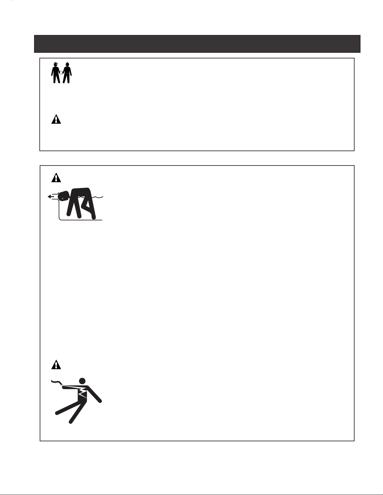
WARNING — Entrapment Avoidance Notice:
The suction outlet connected to a swimming pool or spa pump can pull a high vacuum
if it is blocked. Therefore, if only one suction outlet smaller than 18" x 23" is used,
anyone blocking the suction outlet with their body can be trapped and held against the
suction outlet. Disembowelment or drowning can result. Therefore, if small suction
outlets are used with this pump, to prevent this entrapment and possible death, install
at least two suction outlets in the body of water. Separate these suction outlets as
described in the International Residential Code (IRC), the International Business Code
(IBC), the Consumer Products Safety Council (CPSC) Guidelines for Entrapment Hazards:
Making Pools and Spas Safer or ANSI/IAF-7 Standard for Suction Entrapment Avoidance
in Swimming Pools, Wading Pools, Spas, Hot Tubs and Catch Basins. If suction outlets
are not used, additional entrapment avoidance measures as described in the CPSC
Guidelines or ANSI/IAF-7 should be employed.
iii
The covers used on suction outlets should be approved and listed as conforming to the
currently published edition of ANSI/ASME A112.19.8 Standard covering Suction Fittings
for Use in Swimming Pools, Wading Pools, Spas and Hot Tubs. These covers should be
inspected regularly and replaced if cracked, broken or older than the design lifetime
indicated on them by the manufacturer. The maximum possible flow rate of this pump
should be less than or equal to the maximum approved flow rate indicated on the suction
outlet cover by the manufacturer. THE USE OF UNAPPROVED COVERS OR ALLOWING
USE OF THE POOL OR SPA WHEN COVERS ARE CRACKED OR BROKEN CAN
RESULT IN HAIR ENTANGLEMENT WHICH CAN RESULT IN DEATH.
WARNING — Risk of electrical shock or electrocution.
This pool pump must be installed by a licensed or certified electrician or a qualified pool
serviceman in accordance with the National Electrical Code and all applicable local codes
and ordinances. Improper installation will create an electrical hazard which could result in
death or serious injury to pool users, installers, or others due to electrical shock, and may
also cause damage to property.
Always disconnect power to the pool pump at the circuit breaker before servicing the
pump. Failure to do so could result in death or serious injury to serviceman, pool users
or others due to electric shock.
IntelliFlo Installation and User’s Guide
Page 6
iv
IMPORTANT SAFETY PRECAUTIONS (continued)
WARNING — Water temperature in excess of 100° Fahrenheit may be hazardous to your health. Prolonged
immersion in hot water may induce hyperthermia. Hyperthermia occurs when the internal
temperature of the body reaches a level several degrees above normal body temperature of
98.6° F. (37° C.). The symptoms of hyperthermia include: drowsiness, lethargy, dizziness,
fainting, and an increase in the internal temperature of the body.
The effects of hyperthermia include: 1) Unawareness of impending danger. 2) Failure to
perceive heat. 3) Failure to recognize the need to leave the spa. 4) Physical inability to exit
the spa. 5) Fetal damage in pregnant women. 6) Unconsciousness resulting in danger of
drowning.
WARNING — The use of alcohol, drugs, or medication can greatly increase the risk of fatal
hyperthermia in hot tubs and spas.
WARNING — To reduce the risk of injury, do not permit children to use this product unless they are closely
supervised at all times.
WARNING — For units intended for use in other than single-family dwellings, a clearly labeled emergency
switch shall be provided as part of the installation. The switch shall be readily accessible to
the occupants and shall be installed at least 5 feet (1.52 m) away, adjacent to, and within
sight of, the unit.
WARNING — When setting up pool water turnovers or flow rates the operator must consider local codes
governing turnover as well as disinfectant feed ratios.
CAUTION — Install the pump a minimum of five (5) feet from the inside wall of the pool and spa. Canadian
installations require a minimum of three (3) meters from pool water.
CAUTION — A No. 8 AWG or larger conductor must be wired to the motor bonding lug.
CAUTION — This pump is for use with permanently installed pools and may also be used with hot tubs and
spas if so marked. Do not use with storable pools. A permanently installed pool is constructed
in or on the ground or in a building such that it cannot be readily disassembled for storage. A
storable pool is constructed so that it may be readily disassembled for storage and reassembled
to its original integrity and has a maximum dimension of 18 feet (5.49 m) and a maximum wall
height of 42 inches (1.07 m).
CAUTION — For hot tubs and spa pumps, do not install within an outer enclosure or beneath the skirt of a
hot tub or spa unless so marked.
CAUTION — IntelliFlo is capable of generating systems pressures up to 50 psi. Installers must ensure
that all system components are rated to withstand at least 50 psi. Over pressurizing the
system can result in catastrophic component failure or property damage.
General Installation Information
• All work must be performed by a licensed electrician, and must conform to all national, state,
and local codes.
• Install to provide drainage of compartment for electrical components.
IntelliFlo Installation and User’s Guide
Page 7
Section 1
Introduction
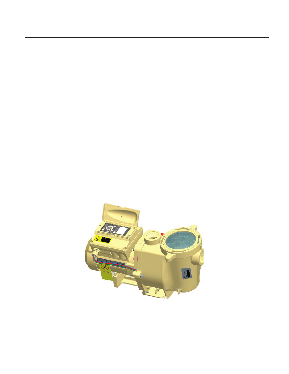
IntelliFlo Overview
The IntelliFlo variable-speed pump control system offers pool and spa filter automation and advanced
features that include energy conservation and programmable scheduled water features for your pool, spa,
cleaner, waterfall, and other applications.
The IntelliFlo pump can adapt to any application up to 130 gallons per minute, you simply program IntelliFlo to
suit the application. IntelliFlo then dials in the perfect operating conditions.
IntelliFlo can reduce energy cost by as much as 90% based on a pool size up to 15,000 gallons, one turn
per day with a 24 hour cycle.
IntelliFlo constantly monitors water flow and electrical current to ensure that the filtration system is operating
at peak efficiency. This can result in maximum energy efficiency savings never before possible – up to 90%
over conventional pumps. The system protects against loss of prime or impedance of flow, under and over
voltage situations, and thermal overload or freezing.
1
With IntelliFlo there’s no need for pump curves and hydraulic calculations to determine the right pump for
the job. Just set the program for your pool size and desired turnover, and IntelliFlo does the rest.
IntelliFlo variable speed pump
IntelliFlo Installation and User’s Guide
Page 8

2
IntelliFlo Features
• Sizes itself to any pool
• Reduces energy cost by as much as 90%
• Protects against loss of prime or flow blockage
• Prevents thermal overload
• Detects and prevents damage from under and over voltage conditions
• Protects against freezing
• Can communicate with an IntelliTouch or IntelliComm system via a two-wire connection
• Easy to read operator control panel LCD display
• Operator control panel buttons for pump modes
• Built-in strainer pot and volute
• Ultra energy-efficient TEFC Square Flange Motor
• Compatibility with most cleaning systems, filters, and jet action spas
• 16-button LCD control panel
• Drive assembly features permanent magnet synchronous motor
• Heavy-duty, durable construction designed for long life
• Internal 24-hour clock for setting controlled on/off times for filtering and up to ten water features
• UL listed
IntelliFlo Motor Assembly
The IntelliFlo three-phase six-pole motor operates at 3450 RPM (at 92% efficiency) and 400 RPM (at
90%). The motor assembly is continually cooled by an external fan. Dual seals on the motor shaft and at the
fan assembly seal the entire motor from any moisture entering the motor assembly. For added protection, a
slinger located in front of the main shaft seal assists in slinging water away from the shaft opening in the
flange.
IntelliFlo Installation and User’s Guide
Page 9
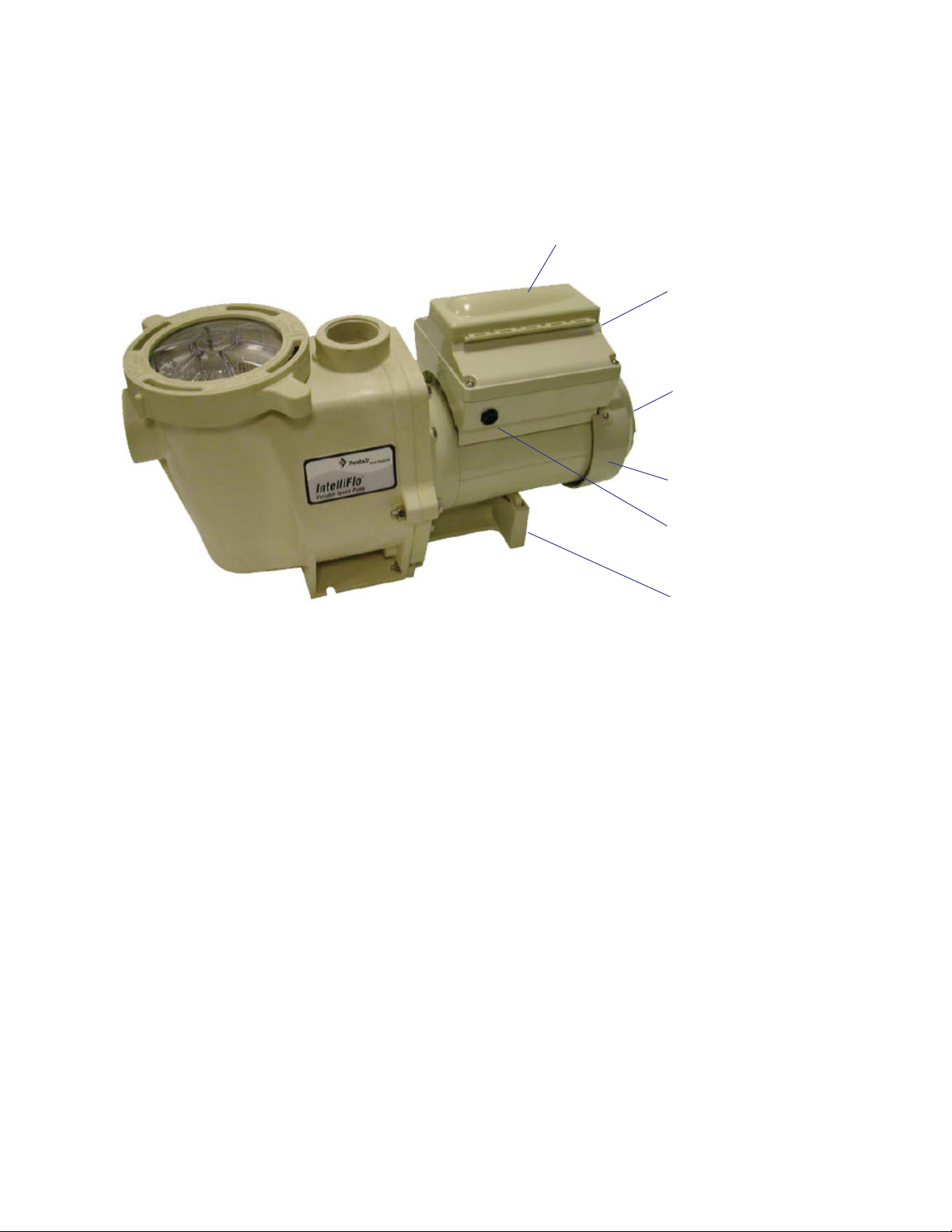
Operator control panel cover
Drive assembly and
electronics enclosure
Motor fan cover
Motor assembly
3
IntelliFlo Motor Assembly
IntelliFlo Motor Features
• Permanent Magnet Synchronous Motor (PMSM)
• High efficiency (3450 RPM 92% and 400 RPM 90%)
• Superior speed control
• Operates at lower temperatures due to high efficiency
• Same technology as deployed in hybrid electric vehicles
• Designed to withstand outdoor environment
• Totally Enclosed Fan Cooled
• Three-phase motor
• 56 Square Flange
• Six-Pole
• Low noise
Communication Port for RS-485
(IntelliTouch and IntelliComm)
Motor stand
IntelliFlo Installation and User’s Guide
Page 10
4
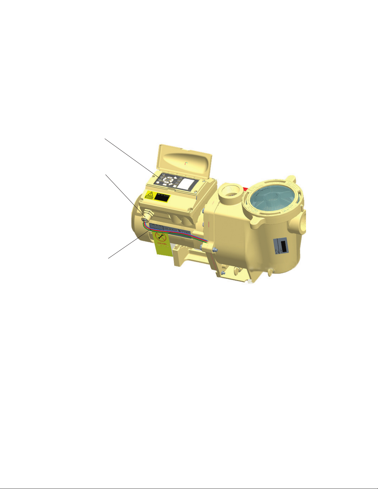
IntelliFlo Drive Assembly and Control Panel
The IntelliFlo drive assembly consists of an operator control panel and the system electronics that drive the
230 VAC single phase (260 VAC~170 VAC) motor. The drive microprocessor controls the motor by
changing the frequency of the current it receives together with changing the voltage to control the rotational
speed.
Operator Control
Panel, buttons and
Liquid Crystal Display
(LCD)
¾” NPT male nipple
Three Wire Harness
Hot (Red), Hot (Red)
Ground (Green / Yellow)
+/- 20% of 230 Volt
IntelliFlo Drive Assembly
Operator Control Panel Features
• Backwash and Rinse — Informs the user when and how to backwash filter media
• Vacuum — Can be preset using duration and flow parameters to save energy
• Filter — Allows pump to run at peak efficiency, saving users up to 90% in energy cost, based on a
pool size up to 15,000 gallons, one turn per day with a 24 hour cycle
• Feature — Ten feature modes can be programmed to control filtration duration, start and stop time,
and frequency for cleaners, water features, spas, and waterfalls
• Manual — Allows the user to override all programming and run the pump using RPM or flow
(GPM) control parameters
IntelliFlo Installation and User’s Guide
Page 11
Operator Control Panel
Filter
mode
Vacuum
mode
Back
Wash
Manual
mode
Enter
Select
Start
Stop
Reset
Feature
2
Feature
1
Menu
Escape
On
War n.
Alarm
IntelliFlo
®
14
1
2 3
4
5
6
8
9
10
11
15
12
13
7
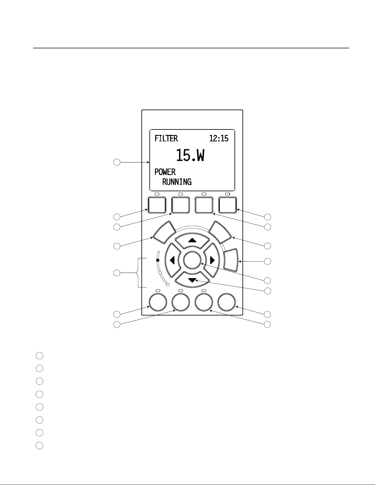
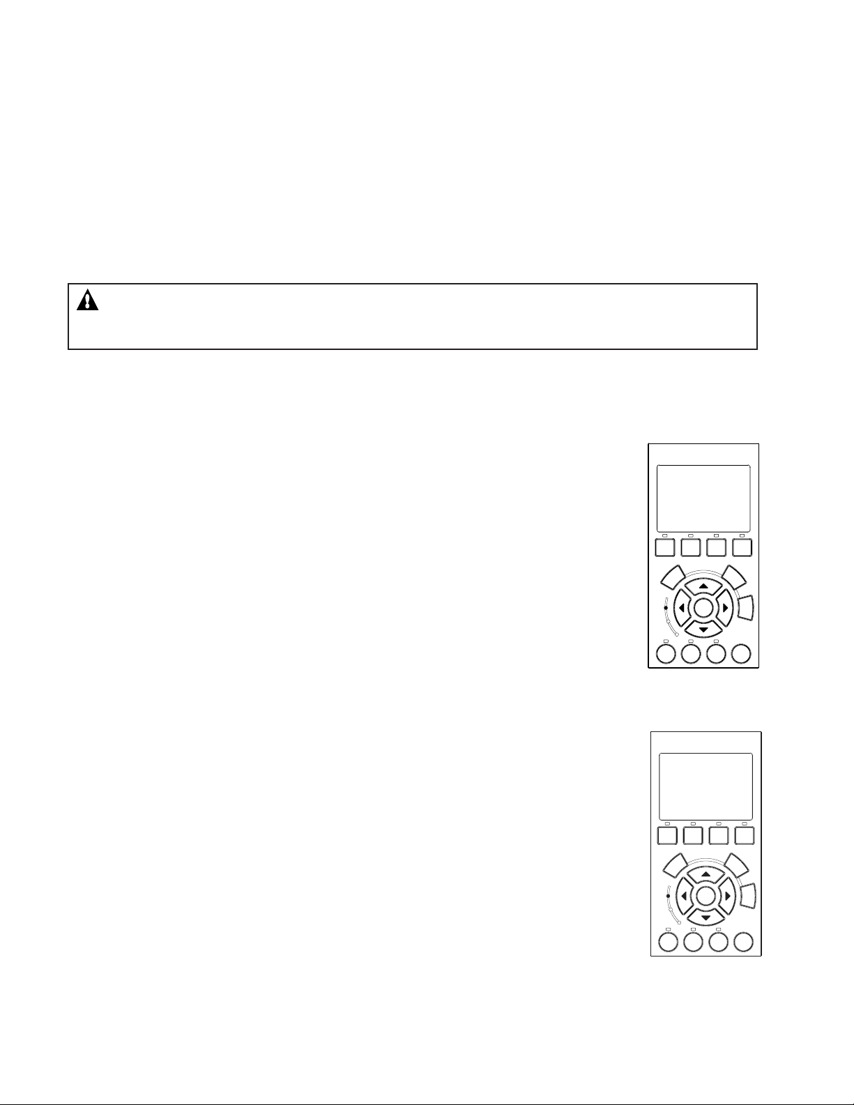
This section describes the operator control panel controls and LEDs.
IntelliFlo Operator Control Panel
5
Section 2
Controls and LEDs
1
Filter button/LED: Starts Filter mode. The LED is on when Filter mode is active.
2
3
4
5
6
7
8
Vacuum button/LED: Starts Vacuum mode. The LED is on when Vacuum mode is active.
Backwash button/LED: Starts Backwash mode. The LED is on when Backwash mode is active.
Manual button/LED: Starts Manual mode. The LED is on when Manual mode is active.
Select button: Display available menu items or enters edit mode for changing a value on line two of the display.
Escape button: Go to the next level up in the menu structure or stop editing the current setting.
Menu button: Access the menu items if the pump is stopped.
Enter button: Save current menu item setting. Also, press this button to acknowledge alarms and warning alerts.
IntelliFlo Installation and User’s Guide
Page 12

6
Controls and LEDs (Continued)
9
Arrow buttons:
• Up arrow: Move one level up in the menu tree or increase a digit when editing a setting.
• Down arrow: Move one level down in the menu tree or decrease a digit when editing a setting.
• Left arrow: Move cursor left one digit when editing a setting.
• Right arrow: Move cursor right one digit when editing a setting.
10
Feature 1 button: Starts Feature 1 mode. The LED is lit when mode is active.
11
Feature 2 button: Starts Feature 2 mode. The LED is lit when mode is active.
12
Start/Stop button: Start or Stop the pump. When the LED is lit it indicates that the pump is currently running or
in a mode to start automatically.
13
Reset button: Reset alarm or alert.
LEDs
On: This green LED is on when IntelliFlo is powered on.
14
Warning: This LED is on if a warning condition is present.
Alarm: This LED is on if an alarm condition has occurred.
15
Control Panel LCD Display
LCD Display Lines:
• Line 1 - Mode and time. To set A.M. and P.M. time, refer to “Time and Contrast Menu” on page 22.
• Line 2 - Data
• Line 3 - Name of data in line 2
• Line 4 - Run status
IntelliFlo Installation and User’s Guide
Page 13
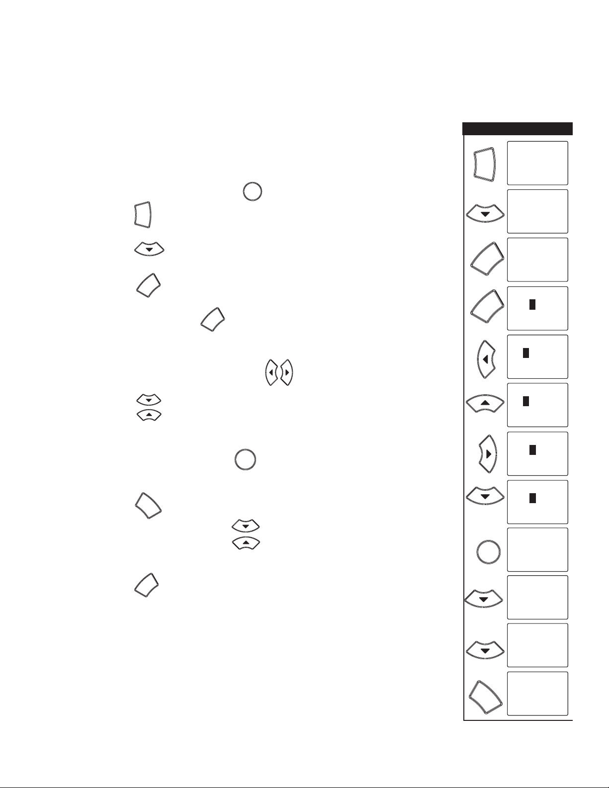
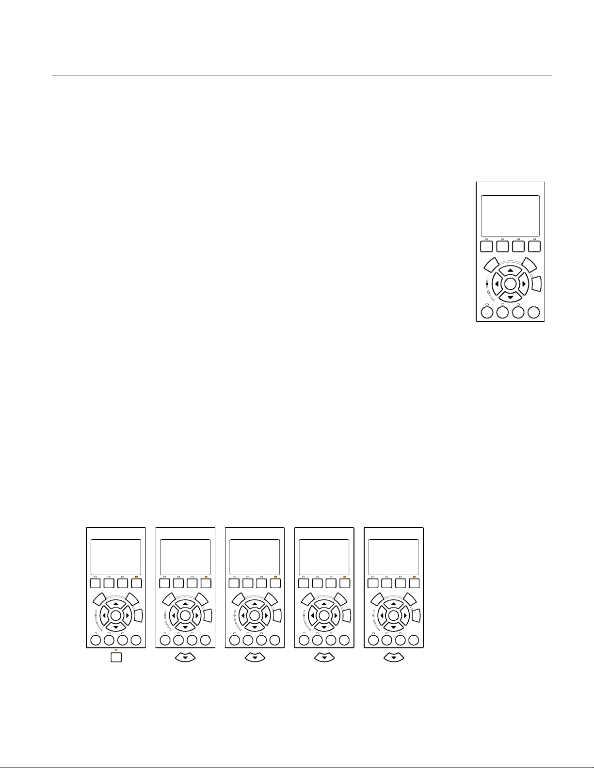
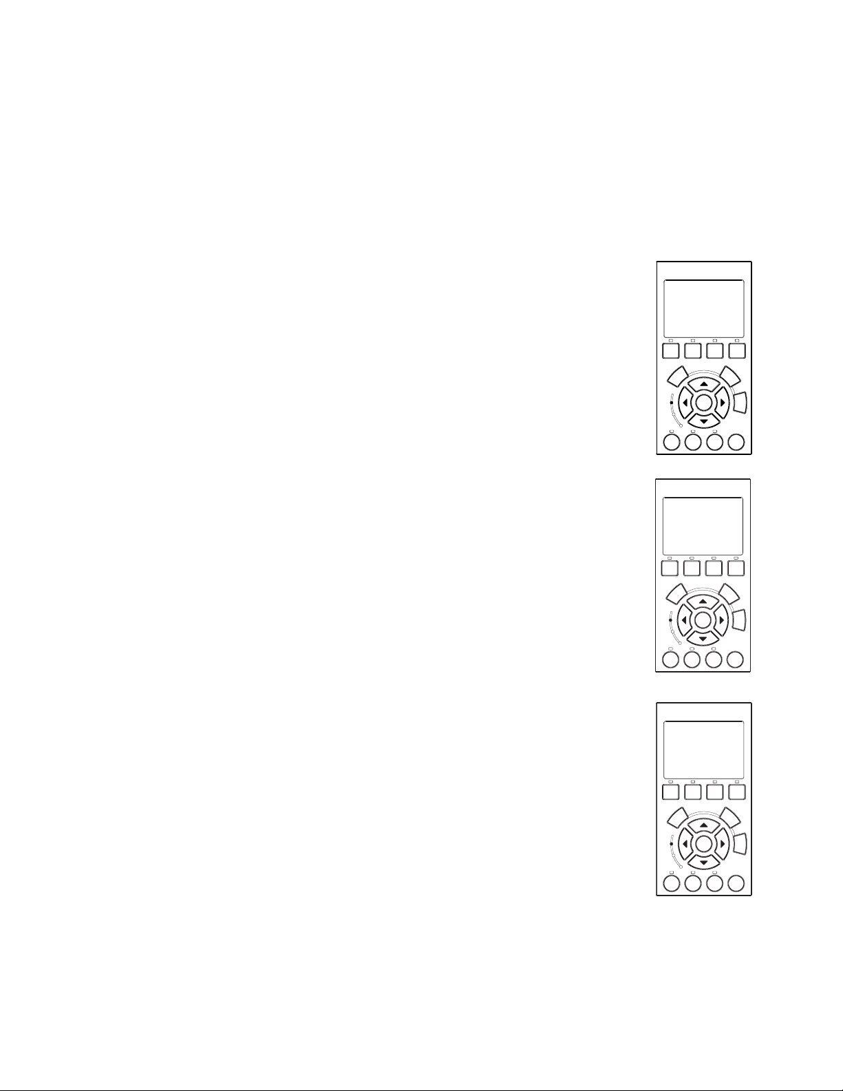
Navigating the Menu Structure
Before navigating the control panel menu structure, first familiarize yourself with the menu buttons. To
change a parameter setting, use the Left and Right arrow buttons to select the digit, then the Up and Down
arrow buttons to edit the digit. The following example shows how to set the GPM and priming time in the
“Priming” menu (see page 14).
Priming Mode Example
7
To set the “Priming” mode settings:
1. Ensure that the green power LED is on and the pump is stopped.
If the pump is running, press the Start/Stop button.
2. Press the Menu button. “Pool Data” is displayed.
Menu
Start
Stop
3. Press the Down arrow to select “Priming”.
4. Press the Select button to access “Max Priming Flow” setting.
5. Set the GPM: Press the Select button to set the gallons per minute
Select
Select
(GPM) value.
6. To change the GPM value, press the Left and Right arrows to select
which digit to modify.
Press the Up and Down arrows to change the selected digit. For setting
values, see “Priming menu options” below.
7. When you are done, press the Enter button to save the changes. To
Enter
cancel any changes.
Press the Escape button to exit edit mode without saving.
Escape
Menu
Select
Select
5X
MENU 12:15
Pool Data
MENU 12:15
Priming
Priming
12:15
55. GPM
Max Priming Flow
Priming
12:15
0055. GPM
Max Priming Flow
Priming
12:15
0055. GPM
Max Priming Flow
Priming
12:15
0065. GPM
Max Priming Flow
Priming
12:15
0065. GPM
Max Priming Flow
Priming
12:15
0060. GPM
Max Priming Flow
8. Set the priming time: Use the Up and Down arrows to select “Max
Priming Time” and “System Priming Time.”
Press the Select to edit the setting.
Select
9. Repeat steps 5, 6, and 7 to edit the setting.
IntelliFlo Installation and User’s Guide
Enter
Escape
12:15Priming
60. GPM
Max Priming Flow
12:15Priming
15. MIN
Max Priming Time
12:15Priming
0. MIN
System Priming Time
MENU 12:15
Priming
Page 14

8
Blank Page
IntelliFlo Installation and User’s Guide
Page 15
This section describes how to use the IntelliFlo pump control panel.
FILTER
1:37
43.GPM
FLOW
RUNNING Schedule
MANUAL
12:15
15.W
POWER
STOPPED
MANUAL
12:15
10.RPM
ACTUAL SPEED
STOPPED
MANUAL
12:15
13.GPM
FLOW
STOPPED
MANUAL
12:15
10.RPM
Set SPEED
STOPPED
MANUAL
12:15
580.GPM
Set FLOW
STOPPED
Metering the System
9
Section 3
Operating IntelliFlo
The first step to operating and programming IntelliFlo is to know what is being used in the
pool system. After the devices are selected you can then set valves for the appropriate
features and use the “Manual” mode to measure flow rates for the types or series of
devices that require flow. When an appropriate flow rate or rates are found for a device
or series of devices, you should note that flow rate for programming later.
Note: If the pool system uses a filter, always monitor pressure at the filter when
changing the speed (RPM) or flow (GPM) from IntelliFlo.
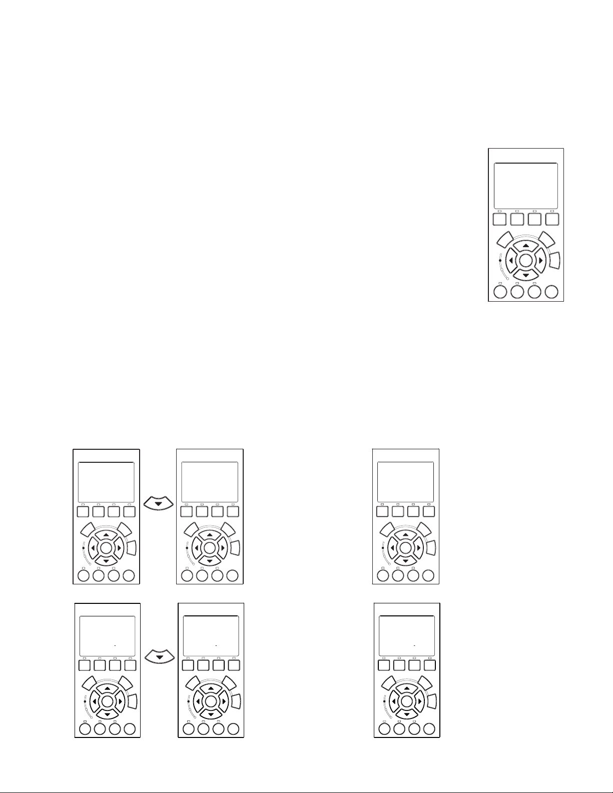
Manual Mode
Operating IntelliFlo in manual mode is typically used for service and testing purposes only.
To operate IntelliFlo in manual mode:
1. Ensure that the green power LED is on.
2. Press the Manual button.
3. Use the Up and Down arrow buttons to view the current power, actual speed and flow:
• Power Menu (Watts): Displays current power to the motor shaft in continuous watts
• Actual Speed (RPM): Displays RPM speed when flow and RPM control is used
• Actual Flow (GPM): Displays actual flow when using flow control
• Set Speed (RPM): Set IntelliFlo to run at a continuous speed
• Set Flow (GPM): Set IntelliFlo in flow control to allow the pump to change speed to manage the
flow rate based on system changes
Filter
mode
On
Warn.
Alarm
Feature
IntelliFlo
Vacuum
mode
Select
Feature
1
®
Back
Manual
Wash
mode
Escape
Menu
Enter
Start
Reset
Stop
2
Filter Vacuum
On
Warn.
Alarm
Feature
1
IntelliFlo
Select
Enter
Feature
2
Manual
®
Back
Manual
Wash
Escape
Start
Reset
Stop
Filter Vacuum
Select
Menu
On
Warn.
Alarm
Feature
1
IntelliFlo
Back
Wash
Enter
Start
Feature
Stop
2
®
Escape
®
IntelliFlo
Manual
Menu
On
Warn.
Alarm
Reset
Filter Vacuum
Select
Feature
1
Feature
2
Enter
Back
Manual
Wash
Escape
Start
Reset
Stop
Filter Vacuum
Select
Menu
On
Warn.
Alarm
Feature
1
IntelliFlo
Back
Wash
Enter
Start
Feature
Stop
2
®
Escape
®
IntelliFlo
Manual
Menu
On
Warn.
Alarm
Reset
Filter Vacuum
Select
Feature
1
Feature
Back
Manual
Wash
Escape
Menu
Enter
Start
Reset
Stop
2
Note: No sensors except the flow control will work while in “Manual” mode. Suction Blockage will
not work in this mode.
IntelliFlo Installation and User’s Guide
Page 16
10
MANUAL
12:15
Set SPEED
STOPPED
MANUAL
12:15
Set SPEED
STOPPED
MANUAL
12:15
Set SPEED
STOPPED
0010.RPM 1010.RPM0010.RPM
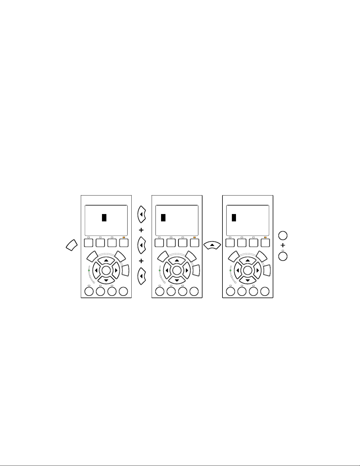
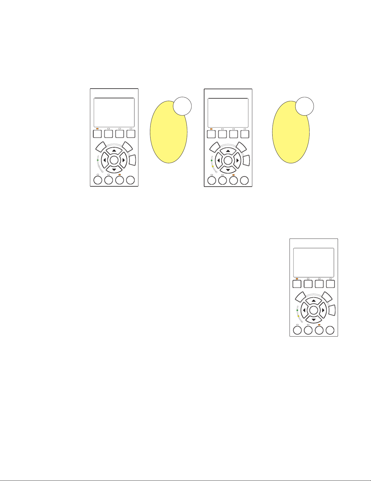
Manual Mode (Continued)
To change the Set Flow and Set Speed features:
1. Ensure that the green power LED is on.
2. Press the Manual button (LED is on).
3. Set Flow: Use the Up and Down arrow buttons to select Set Flow, then press the Select button to
edit the setting.
4. To change the setting, press the Left and Right arrows to select which digit to modify, then use the
Up and Down arrows to change the selected digit. The preset flow values can be set to 15 to 130
GPM (default 50 GPM).
5. When you are done, press the Enter button to save the changes. To cancel any changes, press the
Escape button to exit edit mode without saving.
6. Set Speed: Use the Up and Down arrows to select Set Speed, then press the Select button to edit
the setting. The preset speed can be set to 400 to 3450 RPM maximum (default 1000 RPM).
IntelliFlo
Filter Vacuum
Select
Select
On
Warn.
Alarm
Feature
Feature
1
Cursor hi-lights in
Cursor Hi-lights
in Black
Enter
2
black
Back
Wash
Start
Stop
®
Escape
Manual
Reset
Enter
2
digit
Wash
®
Back
Manual
Escape
Menu
Start
Reset
Stop
IntelliFlo
Filter Vacuum
Select
Menu
On
Warn.
Alarm
Feature
Feature
1
Left/Right arrow
Arrow Keys to
buttons to change
change Values
IntelliFlo
Filter Vacuum
Select
On
Warn.
Alarm
Feature
Feature
1
Press the Enter
Hit Enter and
button to save.
Start/Stop
Press Start/Stop
®
Back
Manual
Wash
Escape
Enter
Start
2
Reset
Stop
Enter
Start
Stop
Menu
7. To change the setting, press the Left and Right arrows to select which digit to modify, then use the
Up and Down arrows to change the selected digit.
8. When you are done, press the Enter button to save the changes. To cancel any changes, press the
Escape button to exit edit mode without saving.
IntelliFlo Installation and User’s Guide
Page 17

Manual Mode (Continued)
9. Press the Start/Stop button (LED is on) to run IntelliFlo in “Manual” mode (LED is on). The pump
will start and control the flow or speed using the last settings made. After the button is pressed, the
display shows “Running.” To stop IntelliFlo, press the Start/Stop button (LED is off). The display
will show “Stopped.”
Note: While IntelliFlo is running in Manual mode, you can view the current power
consumption and what actual speed is being used.
10. Change Flow and Speed settings while the IntelliFlo is running: The Set Flow and Set Speed
settings can be changed on the fly while the pump is running. To change the flow and speed settings,
perform steps 3 through 8.
• When “Set Flow” is used IntelliFlo will prime then ramp to the current flow rate
• It takes the IntelliFlo about 60 seconds to two minutes to find a flow rate after it is primed. This is best
seen in Actual Speed status display
• While changing the Set Flow setting, IntelliFlo will reprime after a value is changed
11
• While changing the Set Speed setting, IntelliFlo will immediately ramp to the current speed
11. To stop the pump, press the Start/Stop button.
IntelliFlo Control Panel Menu
Use the control panel menu to setup and configure IntelliFlo.
To access the menu features:
• Ensure that the pump is stopped. Press the Menu button. Use the Up or Down arrow button to
scroll through the menu items. Use the Select button to select a menu item. Press the Enter button
to save a setting. Press the Escape button to move up a level from a selected menu item.
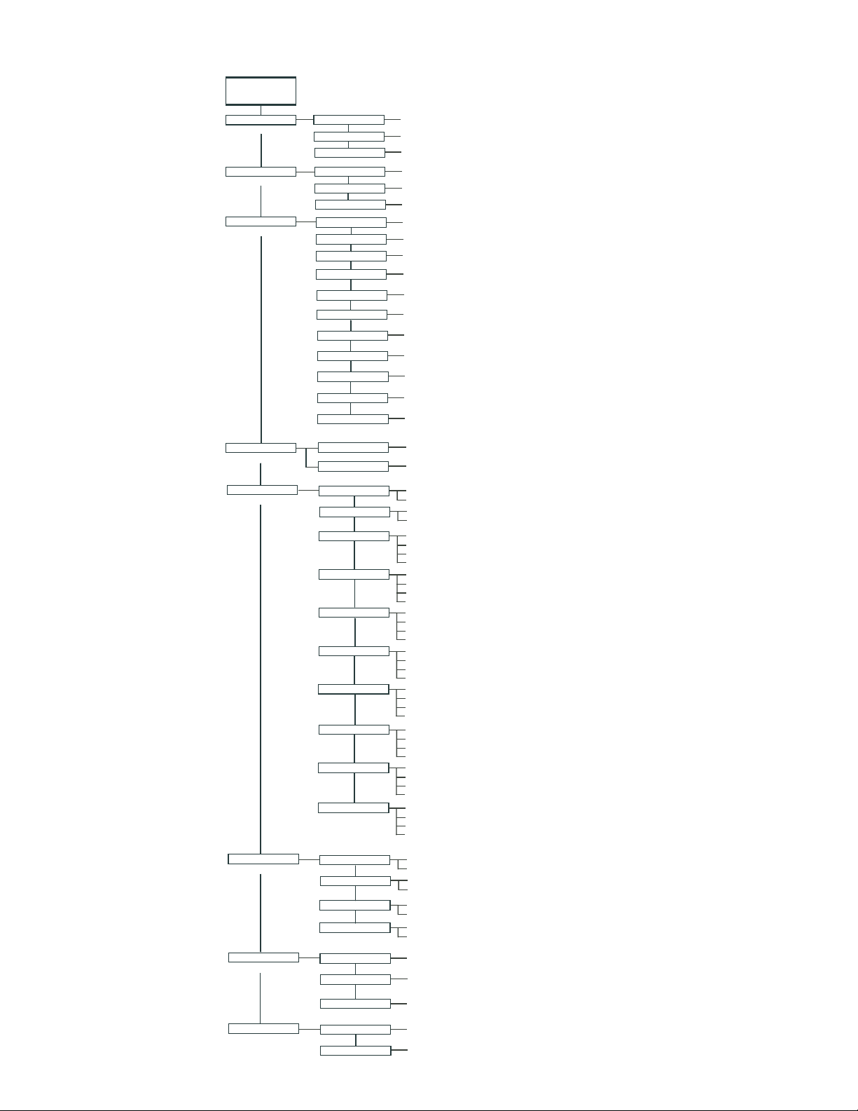
Menu Structure
The IntelliFlo menu structure is shown on the following page.
IntelliFlo Control Panel with IntelliComm or IntelliTouch
• The IntelliFlo control panel remains active when the IntelliFlo is connected to an IntelliComm. For
more information see page 29.
• The IntelliFlo control panel is disabled when the Intelliflo is communicating with an IntelliTouch.
"DISPLAY NOT ACTIVE!" will be displayed. For more information see page 31.
IntelliFlo Installation and User’s Guide
Page 18
12
Main Structure
MAIN SCREEN
POOL DATA
(page 13)
PRIMING
(page 14)
FILTER
(page 16)
TIME / CONTR
(page 22)
FEATURES
(page 23)
Press MENU button to access menu items
Address
Water Temp
Pool Volume
Max Priming Flow
Max Priming Time
Sys Priming Time
Clean Filter Pressure
Turnovers per Day
Cycles per Day
Start Cycle 1
Stop Cycle 1
Start Cycle 2
Stop Cycle 2
Start Cycle 3
Stop Cycle 3
Start Cycle 4
Stop Cycle 4
Clock
Contrast Level
Features 1
Features 2
Features 3
Features 4
Features 5
Features 6
Features 7
Features 8
Features 9
M.O Flow
(1 - 16) [Note: 1-8 when connected to IntelliTouch]
(68˚ - 104˚ F)
(1 - 1000 Kgal)
(30 - 160 gpm)
(1 - 15 min.)
(0 - 5 min.)
(1 - 50 min.)
(1 - 8 counts)
(1 - 4 counts)
(hr:mm - AM/PM)
(hr:mm - AM/PM)
(hr:mm - AM/PM)
(hr:mm - AM/PM)
(hr:mm - AM/PM)
(hr:mm - AM/PM)
(hr:mm - AM/PM)
(hr:mm - AM/PM)
(hr:min - AM/PM)
(0 - 9)
Set Flow (15 - 130 gpm)
Set Duration (0:01 - 10:00)
Set Flow (15 - 130 gpm)
Set Duration (0:01 - 10:00)
Disable/Enable
Set Flow (15 - 130 gpm)
Set Start Time (hr:mm AM/PM)
Set Stop Time (hr:mm AM/PM)
Disable/Enable
Set Flow (15 - 130 gpm)
Set Start Time (hr:mm AM/PM)
Set Stop Time (hr:mm AM/PM)
Disable/Enable
Set Flow (15 - 130 gpm)
Set Start Time (hr:mm AM/PM)
Set Stop Time (hr:mm AM/PM)
Disable/Enable
Set Flow (15 - 130 gpm)
Set Start Time (hr:mm AM/PM)
Set Stop Time (hr:mm AM/PM)
Disable/Enable
Set Flow (15 - 130 gpm)
Set Start Time (hr:mm AM/PM)
Set Stop Time (hr:mm AM/PM)
Disable/Enable
Set Flow (15 - 130 gpm)
Set Start Time (hr:mm AM/PM)
Set Stop Time (hr:mm AM/PM)
Disable/Enable
Set Flow (15 - 130 gpm)
Set Start Time (hr:mm AM/PM)
Set Stop Time (hr:mm AM/PM)
Disable/Enable
Set Flow (15 - 130 gpm)
Set Run Time (0:01 - 00:59)
Set Interval Time (0:02 - 4:15)
EXT. CONTROL
(page 29)
BACKWASH
(page 33)
VACUUM
(page 35)
IntelliFlo Installation and User’s Guide
Program 1
Program 2
Program 3
Program 4
Backwash Flow
Backwash Duration
Rinse Time
Vacuum Flow
Vacuum Duration
Disable/Enable
Set Flow (15 130 gpm) / Time Delay Stop (hr:mn) (0:00 - 0:10)
Disable/Enable (15 - 130 gpm)
Set Flow (15 130 gpm) / Time Delay Stop (hr:mn) (0:00 - 0:10)
Disable/Enable
Set Flow (15 130 gpm) / Time Delay Stop (hr:mn) (0:00 - 0:10)
Disable/Enable
Set Flow (15 130 gpm) / Time Delay Stop (hr:mn) (0:00 - 0:10)
(15 - 130 gpm)
(0:01 - 1:00)
(0:01 - 1:00)
(15 - 130 gpm)
(0:01 - 10:00)
Page 19

Pool Data Mode
MENU
12:15
Pool Data
Pool Data
12:01
Pump Address
1
Pool Data
12:15
Pool Volume
31.kGAL
Pool Data
12:15
Water Temperature
75.F
Use the Pool Data menu to configure IntelliFlo for the pool and spa system. From this menu you can set an
address for the IntelliFlo pump when connected to an IntelliTouch system, set the volume of pool water, in
1000’s of gallons (kgal) and estimated pool water temperature.
To access the Pool Data menu:
1. Ensure that the green power LED is on and the pump is stopped.
2. Press the Menu button.
IntelliFlo
13
®
3. Press the Up and Down arrow buttons to scroll through the menu items. Press the
Select button to access the “Pool Data” menu.
4. To enter the pump volume (pool size): Press the Select button to access “Pool
Volume” setting. To enter the pool volume setting, see step 7.
The “Pool Volume” value is expressed as 1000’s of gallons (Kgal). Enter from 1 to
1000 Kgal for the pool volume. The volume number can be a close estimate, although
the more accurate the better the turns will be done when employing filter mode. Filter
mode uses this value in coordination with the parameters from Filter mode to sustain
turn rates, flows, and times.
5. To set the water temperature: Use the Up and Down arrows to select “Water
Temperature”. To set the water temperature, see step 7.
Enter the current water temperature from 68° F - 104° F (Default 75° F.) The “Water
Temp” is only for the accuracy of the flow sensor. Temperature accuracy is not
critical, just enter an approximate temperature. When the IntelliFlo is connected to an
IntelliTouch system, water and air temperature information is provided by the system
sensors. The flow reading on the IntelliFlo is –0 / +2 GPM. The closer the
temperature to the actual temperature, the more accurate the flow reading on the
IntelliFlo control panel LCD will be while it’s running.
6. To enter the pump address: Press the Select button to access the “Pump Address”
setting. To enter the IntelliFlo pump address, see step 7.
This setting is only used if IntelliFlo is connected to the IntelliTouch system. The
“Pump Address” identifies the pump number (1-16) that is displayed on the
IntelliTouch control panel for programming. For example, if there are multiple IntelliFlo
pumps, pump address 1 can be name as “Spa Pump,” in the IntelliTouch control panel.
The IntelliTouch system can address and control up to eight different pumps using the
RS-485 COM port connection. Note: IntelliFlo pumps cannot be connected in
series with other pumps. Check valves must be used when an IntelliFlo is used in
parallel with other pumps.
7. Press the Select button to change the current setting.
8. To enter a new setting, press the Left and Right arrows to select which digit to modify,
then use the Up and Down arrows to change the selected digit.
Filter Vacuum
Select
Enter
On
Warn.
Alarm
Feature
Feature
2
1
IntelliFlo
Pool Data
Pump Address
Filter Vacuum
Select
Enter
On
Warn.
Alarm
Feature
Feature
2
1
IntelliFlo
Pool Data
31.kGAL
Pool Volume
Filter Vacuum
Select
Enter
On
Warn.
Alarm
Feature
Feature
2
1
IntelliFlo
Pool Data
75.F
Water Temperature
Filter Vacuum
Select
Enter
On
Warn.
Alarm
Feature
Feature
2
1
Back
Manual
Wash
Escape
Menu
Start
Reset
Stop
®
12:01
Back
Manual
Wash
Escape
Menu
Start
Reset
Stop
®
12:15
Back
Manual
Wash
Escape
Menu
Start
Reset
Stop
®
12:15
Back
Manual
Wash
Escape
Menu
Start
Reset
Stop
9. When you are done, press the Enter button to save the changes. To cancel any
changes, press the Escape button to exit edit mode without saving.
IntelliFlo Installation and User’s Guide
Page 20
14
MENU
12:37
Priming
Priming
12:44
Max Priming Flow
55.GPM
Priming Mode
To “prime” a pump means filling the pump and suction pipe with water. This process evacuates the air from all
the suction lines and the pump. It may take several minutes to prime depending on the depth of water, pipe size
and length. It is easier to prime a pump if you allow all the air to escape from the pump and pipes. The water
cannot enter unless the air can escape. Pumps do not hold prime, the pool piping system has that task.
Priming is a function used every time the motor is started with a flow as reference. The “Priming Flow” function
ensures the proper operation of the pump. The “System Priming Time” function ensures proper operation of the
whole pool system. When the pump is priming, the control panel LCD displays “Priming” and then for a moment
displays “Primed” when priming is complete.
CAUTION: To avoid permanent damage to the IntelliFlo pump, before starting the system, fill the IntelliFlo
housing strainer with water so that the pump will prime correctly. If there is no water in the stainer the pump will
not prime.
Priming Menu
To enter maximum priming flow (GPM):
1. Ensure that the green power LED is on and the pump is stopped.
2. Press the Menu button. “Pool Data” is displayed.
3. Press the Up or Down arrows to select the “Priming” menu.
4. To set the Max Priming Flow (GPM): Press the Select button to access the “Max
5. To set the Max Priming Time: Press the Select button to access the “Max
IntelliFlo
Priming Flow” setting. To enter the maximum flow range (GPM) during the
Filter Vacuum
priming cycle, see step 7.
On
Warn.
Alarm
Feature
Select
Enter
Feature
2
1
The “Max Priming Flow” value is entered as gallons per minute (GPM), from 30
to 160 GPM. The default is 55 GPM. The “Max Priming Flow” is a critical
parameter for the pool and equipment. Every time the pump starts this parameter
will negotiate the maximum flow of the pump. If the flow is too high, equipment
damage can occur. If the flow is to low the pump will not prime. This “flow” is
system dependent and may require iteration. The pump will never flow more than
this parameter is set to, however, it is common for the pump to ramp up and down
quickly while priming. Always try to keep this flow as low as possible for cost
savings and safety.
Priming Time” setting. To enter the maximum time for priming before “PRIMING
IntelliFlo
Priming
55.GPM
Max Priming Flow
ERROR”, see step 7 on the following page.
The “Max Priming Time” value is entered in minutes, from 1 to 15 minutes. The
Filter Vacuum
default is 15 minutes. Use this parameter to set the time that you want IntelliTouch
On
Warn.
Alarm
Feature
Select
Enter
Feature
2
1
to try and prime before it reports an error. Remember that the IntelliFlo will attain
prime every time it starts and goes through this cycle. The IntelliFlo mechanical
seal can withstand about 15 minutes before severe damage occurs. You can set
this range between 1 minute to 15 minutes. The lower the time the quicker you will
get a priming error if the system is difficult to prime. A well plumbed pool without
having the strainer removed should prime in less than 30 seconds. If the strainer
has been removed for cleaning and a substantial amount of air is in the system it should prime in
about 60 to 90 seconds on the average, however, all systems will be different.
Wash
®
Back
Manual
Escape
Menu
Start
Reset
Stop
®
12:44
Back
Manual
Wash
Escape
Menu
Start
Reset
Stop
IntelliFlo Installation and User’s Guide
Page 21

Priming Mode (Continued)
Priming
12:54
Max Priming Time
15.MIN
Priming
1:03
System Priming Time
0.MIN
15
6. To set the System Priming Time: Press the Select button to access the “System
Priming Time” setting. After the pump is primed it will take sometime before the
system is primed. This time is called “System Priming Time” To enter the maximum
system priming time, see step 7.
The “System Priming Time” value is entered in minutes, from 0 to 5 minutes. The
default is 0 minutes. Remember that the average unit will prime in a short period of
time because the IntelliFlo has the ability to monitor itself to make sure it is primed.
“System Priming Time” is for systems that require high flows that priming flow can
provide but it is deemed that more time is needed to fully relieve all the air. The
builder can program a pre determined amount of time, up to 5 minutes, to aid in
relieving the air from difficult filters or complex vertical plumbing. The “System
Priming Time” should only be used where large air traps become problems within
the system. The display will inform the user when this is engaged and when it is
finished during the priming cycle at each start up cycle.
7. Press the Select button to change the current value.
8. To change the value, press the Left and Right arrows to select which digit to modify,
then use the Up and Down arrows to change the selected digit.
9. When you are done, press the Enter button to save the changes. To cancel any
changes, press the Escape button to exit edit mode without saving.
IntelliFlo
Priming
15.MIN
Max Priming Time
Select
Enter
Feature
2
IntelliFlo
Back
Wash
Start
Stop
®
1:03
Filter Vacuum
On
Warn.
Alarm
Feature
1
Priming
0.MIN
System Priming Time
Filter Vacuum
On
Warn.
Alarm
Feature
1
Back
Wash
Select
Enter
Start
Feature
Stop
2
®
12:54
Manual
Escape
Menu
Reset
Manual
Escape
Menu
Reset
IntelliFlo Installation and User’s Guide
Page 22
16
MENU
1:13
Filter
Filter
1:16
Clean Filter Pressur
14.PSI
Filter
12:00
Turnovers Per Day
1
Filter Mode
IntelliFlo will calculate the required flow rate based on pool size, clean filter pressure, pool turns per day
and cycles per day, and will control the motor speed to keep a constant flow. The filter mode can run
cycles, power save or features. The IntelliFlo internal scheduler will keep track of which function to run.
IntelliFlo is constantly monitoring the filter, when it detects that the system is dirty, it will display an “Alert Service System Soon” message on the control panel display. The user must then clean the filter by
performing a Backwash cycle (see page 33).
Filter Menu
To access the Filter menu settings:
1. Ensure that the green power LED is on and the pump is stopped.
IntelliFlo
®
2. Press the Menu button. Press the Up or Down arrows to select the “Filter” menu.
Press the Select button, “Clean Filter Pressure” is displayed.
3. To set the Clean Filter Pressure: Press the Select button to access the “Clean
Filter Pressure” setting. To edit the pressure setting, see step 6 on the following
page.
This parameter can be set from 1 PSI to 50 PSI. The average setting should be
between 10 PSI and 20 PSI for most pools and filters. The entered PSI value splits
the percentage meter for the filter. The “Service System Soon” alert is activated by
the entered PSI value. When this value is reached the pump stops monitoring flow
rates and starts managing pressure. The value represents the change in pressure
over time from start up (system clean) to present day (system getting dirty). The
changes can come from anywhere in the system, for example clogged skimmers or
pots in pumps. For more information, refer to “Clean Filter Pressure” on page 19.
4. To set the Turnovers Per Day: Press the Select button to access the “Turnovers Per
Day” setting. To edit this setting, see step 6 on the following page.
This setting is the number of times you wish to turn over the water that is setup in the
“Pool Volume” part of the “Pool Data” menu (see page 13).
You can set up to eight turns per day. It is recommended that one turn per day for
energy conservation and requirements be performed for most common residential
pools. Refer to sanitizer recommendation for additional information.
Filter Vacuum
On
Warn.
Alarm
Feature
Back
Wash
Select
Enter
Start
Feature
Stop
2
1
IntelliFlo
Filter
14.PSI
Clean Filter Pressur
Select
Feature
1
IntelliFlo
Filter
Select
Feature
1
Back
Wash
Enter
Start
Stop
2
Back
Wash
Enter
Start
Stop
2
Filter Vacuum
On
Warn.
Alarm
Feature
Turnovers Per Day
Filter Vacuum
On
Warn.
Alarm
Feature
Manual
Escape
Menu
Reset
®
1:16
Manual
Escape
Menu
Reset
®
12:00
Manual
Escape
Menu
Reset
IntelliFlo Installation and User’s Guide
Page 23
Filter Mode (Continued)
Filter
12:08
Cycles Per Day
1
Filter
12:02
Stop Cycle 1
Enabled
9:00 pmpm
Filter
12:10
Start Cycle 2
Disabled
9:10 pmpm
Filter
12:01
Start Cycle 1
Enabled
9:00 am
Filter
12:02
Stop Cycle 1
Enabled
7:59 am
Filter
12:10
Start Cycle 2
Disabled
10:15 am
Filter
12:01
Start Cycle 1
Enabled
8:00 am
5. To set the Cycles Per Day: Press the Select button to access the “Cycles Per Day” setting. To edit
this setting, see step 6.
IntelliFlo uses the Cycles Per Day parameter to calculate how much time it has to
complete its filter job. You can program up to four start and stop cycles per day.
The more time the IntelliFlo is given to operate the less power and flow will be
needed for turning over the pool.
Filter
IntelliFlo
17
®
12:08
Note: Consumers in certain areas are charged lower energy rates at non-peak
Cycles Per Day
hours. To take advantage of this, the IntelliFlo can be programmed to run at
Back
any time of the day. The extremely quiet operation of the IntelliFlo makes it
feasible to operate during the early morning or late at night. The easiest and
Filter Vacuum
Select
Manual
Wash
Escape
best way to optimize flow during filter cycles is by adding or subtracting cycle
Feature
Enter
Start
Feature
2
1
Reset
Stop
time. This way, the desired flow effect, for example, skimming action, can be
achieved while maintaining the desired water turnover rate.
On
Warn.
Alarm
6. Press the Select button to change the current value.
7. To change the value, press the Left and Right arrows to select which digit to modify, then use the Up
and Down arrows to change the selected digit.
8. When you are done, press the Enter button to save the changes. To cancel any changes, press the
Escape button to exit edit mode without saving.
Programming Cycles Per Day
Each cycle has two screens, one for the “Start Cycle” and one for “Stop Cycle”. The following examples
shows one for the cycle start/stop time. Only one cycle is entered in the “Cycles Per Day” parameter.
IntelliFlo
Filter
9:00 am
Start Cycle 1
Enabled
Filter Vacuum
Select
On
Warn.
Alarm
Feature
Feature
2
1
®
12:01
Filter
9:00
Stop Cycle 1
Enabled
Back
Manual
Wash
Escape
Menu
Enter
Start
Reset
Stop
Filter Vacuum
Select
On
Warn.
Alarm
Feature
1
IntelliFlo
Back
Wash
Enter
Start
Feature
Stop
2
®
12:02
Start and Stop
Cycle is displayed
Manual
Enabled or disabled is
displayed depending on
Escape
how many cycles are
Menu
selected
Reset
Filter
9:10
Start Cycle 2
Disabled
Filter Vacuum
Select
On
Warn.
Alarm
Feature
1
IntelliFlo
Back
Wash
Enter
Start
Feature
Stop
2
®
12:10
Escape
This screen shows the filter
cycle as “Disabled” for a start/
stop cycle (Cycles Per Day
Manual
programmed to 1). These
screens will still display even
if they are not enabled.
Menu
Reset
Menu
Filter Vacuum
Select
On
Warn.
Alarm
Feature
1
IntelliFlo
Back
Wash
Enter
Start
Feature
Stop
2
®
Escape
Manual
Reset
IntelliFlo
®
This example will
run the pump for 24
IntelliFlo
®
hours. Start and
Stop Cycle is
displayed
Back
Filter Vacuum
Select
Menu
On
Warn.
Alarm
Feature
Feature
1
Manual
Wash
Enter
Start
Stop
2
Enabled or disabled is
displayed depending on
Escape
how many cycles are
Menu
selected
Reset
Filter Vacuum
On
Warn.
Alarm
Feature
Back
Wash
Feature
Escape
Enter
Start
Stop
2
Select
1
This screen shows the filter
cycle as “Disabled” for a start/
stop cycle (Cycles Per Day
Manual
programmed to 1). These
screens will still display even
if they are not enabled.
Menu
Reset
IntelliFlo Installation and User’s Guide
Page 24

18
Filter Mode (Continued)
Filter Cycle Settings
Note: The control panel is disabled when the Intelliflo is communicating with an IntelliTouch.
"DISPLAY NOT ACTIVE!" will be displayed.
EMANEULAVNOITPIRCSED
rePsrevonruT
yaD
repselcyC
yaD
retliFnaelC
erusserP
elcyCtratS
1
1elcyCpotS
2elcyCtratS
2elcyCpotS
3elcyCtratS
)1tluafeD(8-1
)1tluafeD(selcyC4-1
d
41tluafeD(ISP05-1
)ISP
MM.HH95:21-00:1
00:9tluafeD(mp/ma
)ma
MM.HH95:21-00:1
00:9tluafeD(mp/ma
)mp
MM.HH95:21-00:1
01:9tluafeD(mp/ma
)mp
MM.HH95:21-00:1
luafeD(mp/ma
02:9t
)mp
MM.HH95:21-00:1
03:9tluafeD(mp/ma
)mp
tratS emitemasehtsipotsdnatratsfi(1elcycrofemit
potS emitemasehtsipotsdnatratsfi(1elcycrofemit
tratS ,2wolebsi"yadrepsel
.deretne
potS ,2wolebsi"yadrepselcyC"fI.2elcycrofemit
.deretne
tratS ,3wolebsi"yadrepselcyC"fI.3elcycrofemit
.deretne
"emuloVlooP"ni
.yadrepo
.sutatsretlif
liwolFilletnIeht
.devomeblliw
.)7*42nurl
.)7*42nurlliwolFilletnIeht
cyC"fI.2elcycrofemit
putesretawfoemulovehtyadrepsemitforebmunehT
tsumolFilletnIeht)potsdnatrats(selcycforebmunehT
%001oterusserp-0ehtmorferusserplaitnereffidehT
ebtonnacataddnayalpsidehtninwohseblliw"FFO"
ebtonnacataddnayalpsidehtninwohseblliw"FFO"
onnacataddnayalpsidehtninwohseblliw"FFO"
ebt
3elcyCpotS
4elcyCtratS
4elcyCpotS
Based on “Pool Volume”, “Turnovers per day” and the total number of hours for Cycle 1 + 2 + 3 + 4
the flow must be calculated:
Flow
=
Note: Only enabled cycles are included in the calculation
IntelliFlo Installation and User’s Guide
MM.HH95:21-00:1
04:9tluafeD(mp/ma
)mp
H95:21-00:1
MM.H
05:9tluafeD(mp/ma
)mp
MM.HH95:21-00:1
00:01tluafeD(mp/ma
)mp
×
CycleCycleCycleCycle
+++
potS ,3wo
.deretne
tratS ,4wolebsi"yadrepselcyC"fI.4elcycrofemit
inwohseblliw"FFO"
.deretne
potS ,4wolebsi"yadrepselcyC"fI.
.deretne
""""
dayprTurnoversPoolVolume
4elcycrofemit
4321
lebsi"yadrepselcyC"fI.3elcycrofemit
ebtonnacataddnayalpsidehtninwohseblliw"FFO"
ebtonnacataddnayalpsidehtn
ebtonnacataddnayalpsidehtninwohseblliw"FFO"
Page 25
Filter Mode (Continued)
Service System Soon
Alert
FILTER
1:37
FLOW
RUNNING Schedule
43.GPM
Service System Soon
Alert
Clean Filter Pressure Example
The following example shows the “Clean Filter Pressure” set to 14 PSI.
19
IntelliFlo
FILTER
®
1:37
43.GPM
FLOW
RUNNING Schedule
Back
Filter Vacuum
Select
On
Warn.
Alarm
Feature
Feature
2
1
Pump newly installed and
system run for the first
time
Manual
Wash
Escape
Enter
Menu
Start
Reset
Stop
Filter
10 psi
IntelliFlo
Alert
Service System Soon
Filter Vacuum
Select
On
Warn.
Alarm
Feature
Feature
1
12 months later filter attains
24 psi of internal pressure
which is a 14 psi increase
®
Back
Manual
Wash
Escape
Enter
2
Menu
Start
Reset
Stop
Alert Status
Once the “Alert” is triggered the yellow warning LED is lit and “Alert” is displayed on
the screen. The pump will reduce speed to maintain 14 PSI of head pressure and stop
managing flow. Note the following:
• The % clean filter pressure has reached 100%.
• If parameter is set to 14 PSI every 10% on the display is 1.4 psi on the filter.
• If the parameter is set to 10 PSI every 10% on the display is 1 psi on the filter.
• The filter must be cleaned or backwashed to reduce the pressure. Even if the
system has a cartridge filter the IntelliFlo must be started in Backwash Mode
with a clean filter to reset the fault and "zero" the IntelliFlo's filter status reading.
24 psi
Filter
IntelliFlo
Alert
Service System Soon
Filter Vacuum
Select
On
Warn.
Alarm
Feature
Feature
1
®
Back
Manual
Wash
Escape
Enter
2
Menu
Start
Reset
Stop
Note: For a complete list of IntelliFlo alert warnings, refer to “Alert and
Warning” on page 49.
IntelliFlo Installation and User’s Guide
Page 26

20
Filter Mode (Continued)
Using Filter mode with Features mode
IntelliFlo will start and stop at programmed filter cycles 1-4. The filter cycles can be overridden by
“Feature” (3-9 only) as shown in the example below. This may cause the required filter volume to be
achieved earlier.
The “Feature” function is allowed to take control during “Filter” mode. When the feature function stops,
IntelliFlo will continue in “Filter” mode. If only Feature 3-9 is active during a filter cycle, IntelliFlo will
calculate a new filter cycle.
Example: The IntelliFlo was suppose to run in Filter mode from 1:00 to 11:00 to turnover
10 GPM for 10 hours (10 GPM 10 Hours= 6 kGal).
But because Feature 3 has been running 20 GPM for 4 hours (20 GPM 4 Hours= 4,8 kGal),
the IntelliFlo must stop at 8:00 because; 10 GPM* 3 Hours + 20 GPM 4 Hours= 6,6 kGal.
Flow
20 GPM
Feature 3
10 GPM
Filter
Time
11 4 8 1
“Feature” 1 and 2 do not have time-of-day functions and do not affect the filter cycle time. The active time
for “Feature” 1 and 2 will not be calculated into the reduced cycle time as shown in the above example.
IntelliFlo Installation and User’s Guide
Page 27

Filter Mode (Continued)
Flow Control and Filter Mode
The Filter Mode feature provides the ability of overcoming head pressure loss to provide the required flow
through the plumbing. The flow that the unit can provide is limited by the installed plumbing. If more flow is
demanded than the IntelliFlo can provide, it will ramp to full speed and create pressure.
The following example shows a ramp as flow increases from 50 to 75 GPM.
Speed
Series of
2
small slow
ramps
50 GPM
1
Ramps in
Speed
Quickly
75 GPM
Power and RPM
stabilize and
3
required flow is
attained
21
Valve is moved
Time
IntelliFlo Installation and User’s Guide
Page 28

22
MENU
12:24
Time/Contr
Time/Contr
12:24
Set Time
12:29 amam
Time/Contr
12:36
Contrast Level
5
Time/Contr
12:38
Contrast Level
7
Time and Contrast Menu
Use the “Time and Contr” menu settings to set the IntelliFlo system clock and to adjust the control panel
display contrast. The IntelliFlo system clock controls all scheduled start and stop times, functions, and
programmed cycles. The system clock can store the correct time for up to 96 hours after power is shut off.
After 96 hours the clock must be reset to the correct time.
Setting System Time
To set the IntelliFlo system clock:
1. Ensure that the green power LED is on and the pump is
stopped.
2. Press the Menu button. “Pool Data” is displayed.
3. Press the Up or Down arrows and select “Time/Contr.”
4. Press the Select button to access “Time/Contr” setting.
Filter Vacuum
5. Press the Select button to change the current minutes and hour.
6. To change the minute and hour digits, press the Left and Right
arrow buttons to select which digit to modify, then use the Up
On
Warn.
Alarm
Feature
and Down arrow buttons to change the selected digit. Note,
that the hours selection is from 01 to 11 for A.M. and P.M. The
system time is displayed on the main screen, A.M. and P.M. are not displayed.
7. Press the Enter button to save the setting.
Setting the LCD Backlight Contrast
To change the contrast of the control panel display :
1. Ensure that the green power LED is on and the pump is
stopped.
IntelliFlo
Select
Feature
2
1
IntelliFlo
Time/Contr
®
IntelliFlo
Time/Contr
®
12:24
12:29
Set Time
Select
Feature
2
IntelliFlo
Back
Manual
Wash
Escape
Menu
Enter
Start
Reset
Stop
®
12:38
Back
Manual
Wash
Escape
Menu
Enter
Start
Reset
Stop
®
12:36
Filter Vacuum
On
Warn.
Alarm
Feature
1
Time/Contr
2. Press the Menu button. “Pool Data” is displayed.
3. Press the Up or Down arrows and select “Time/Contr.”
4. Press the Select button.
5. Press the Up or Down arrows and select “Contrast Level.”
6. Press the Select button. The contrast levels are 0 to 9. Avoid
using 0 unless screen is unreadable in bright sun
7. Press the Enter button to save the setting.
IntelliFlo Installation and User’s Guide
Contrast Level
Filter Vacuum
Select
On
Warn.
Alarm
Feature
Feature
2
1
Contrast Level
Back
Manual
Wash
Escape
Menu
Enter
Start
Reset
Stop
Filter Vacuum
On
Warn.
Alarm
Feature
1
Back
Manual
Wash
Feature
Escape
Enter
2
Menu
Start
Reset
Stop
Select
Page 29

Features Mode
The Feature mode can be used with water features such as spa, cleaner, waterfalls, etc. You can schedule
start and stop times for each feature. All Features are operated using Flow control. The Feature mode and
Filter mode are run simultaneously. The three types of features are; Features 1 & 2, Features 3 -9 and
M.O. Flo:
Features 1 and 2
Feature 1 and Feature 2 run for a pre-defined duration with a specifically set flow. If Feature 1 or Feature 2
buttons are pressed, all other Features are temporarily deactivated. Feature 1 or Feature 2 cannot be used
in Backwash Mode. Features 1 and 2 have a higher priority than the pre-programmed Features 3-9. After
the preset duration time for the Feature 1(2), IntelliFlo will switch back to the “Filter” mode if the IntelliFlo
was in “Filter” mode when the Feature 1 (2) button had been pressed. After the preset duration time for the
Feature 1(2), the IntelliFlo will switch back to the “Manual” mode if IntelliFlo was in “Manual” mode when
the Feature 1 (2) button had been pressed.
Features 3 -9
Features 3 through 9 are only active in Filter mode. These features run a set flow for a specified time. The
Features 3-9 can not overlap.
23
M. O. Flo
The M. O. Flo feature automatically increases the pump flow to allow the system heater to check the water
temperature and switch on if necessary. This feature is only active when the pump is running a filter cycle.
Once the heater checks for heat and discovers it must fire it will send a signal back to IntelliFlo to go into
“Heater” mode. M.O. Flo only works during the “Filter” mode selected time cycles
IntelliFlo Installation and User’s Guide
Page 30

24
Features Mode (Continued)
Feature Settings
emaNeulaVnoitpircseD
olF.O.Mdna9-1F
wolFteS
etavitcA:01-3F
erutaeF
emiTnoitaruD:2-1F
emittratS:3F
emitpotS:3F
emittratS:4F
emitpotS:4F
emi
ttratS:5F
emitpotS:5F
emittratS:6F
emitpotS:6F
emittratS:7F
emitpotS:7F
emittratS:8F
emitpotS:8F
emittratS:9F
emitpotS:9F
olF.O.M:01F
emitnuR
olF.O.M:01F
emitlavretnI
1
(
tlaufeD(
MPG031-51
)MPG05tluafeD(
delbasiD/delbanE
)delbasiDtluafeD(
sruoH01-0
)10:00tlaufeD(
MP95:11-MA00:21
)ma00:60tlaufeD(
MP95:11-MA00:21
)ma01:60tlaufeD(
MP95:11-MA00:2
)ma02:60tlaufeD(
MP95:11-MA00:21
)ma03:60tlaufeD(
MP95:11-MA00:21
)ma04:60tlaufeD(
MP95:11-MA00:21
)ma05:60tlaufeD
MP95:11-MA00:21
)ma00:70tlaufeD(
-MA00:21
MP95:11
)ma01:70tlaufeD(
MP95:11-MA00:21
)ma02:70tlaufeD(
MP95:11-MA00:21
)ma03:70tlaufeD(
MP95:11-MA00:21
)ma04:70
MP95:11-MA00:21
)ma05:70tlaufeD(
MP95:11-MA00:21
)ma00:80tlaufeD(
MP95:11-MA00:21
)ma01:80tlaufeD(
setunim01-0
)nim1tluafeD(
setunim552-0
)nim06tluafeD(
tratS
arudemitehT
efrofemittratS
rofemitpotS
tnuR"
wolftesehtta
ehtsi"emitlavretnI"
olF.O.Mrofeulav
01-1erutaefrofwolftes-erP
.evitcaeblliwerutaeFehtdelbanEtessi1enilnieulavfI
.ffodenruteblliwerutaeFehtdelbasiDtessi1enilnieulavfI
.2dna1erutaefrofnoit
.2dna1erutaeFrofdetcelesebtsumnoitarudehT
3eruta
3erutaefrofemitpotS
4erutaefrofemittratS
4erutaefrofemitpotS
5erutaefrofemittratS
5erutaefrofemitpotS
6erutaefrofemittratS
6erutaefrofemitpotS
7erutaefrofemit
7erutaefrofemitpotS
8erutaefrofemittratS
8erutaefrofemitpotS
9erutaefrofemittratS
9erutaef
gninnursinoitcnufolF.O.Mehthcihwrofemitehtsi"emi
"wolftes"ehtfonoitavitcaneewtebemit
IntelliFlo Installation and User’s Guide
Page 31

Features Mode (Continued)
MENU
12:45
Features
Features
12:51
Feature 1
Feature 1
12:54
Set Flow
50.GPM
The functions of the Features groups are shown below:
How to set up the Feature 1 or 2 (Flow and Duration) mode
To access the Features menu:
1. Ensure that the green power LED is on and the pump is stopped.
Feature
Groups
25
Features 1-2
Flow and Duration
Features 3-9
Flow, Start / Stop Time
Flow, Interval, Length of Interval
MOFlo
2. Press the Menu button. Press the Up or Down arrows to select the “Features” menu. Press the
Select button to access the Feature 1 menu settings. The Features 1 menu setting is
displayed.
3. To set the flow rate for Feature 1 or 2: Press the Select button to access the
IntelliFlo
Feature 1 “Set Flow” setting. To edit the flow rate (GPM) setting, see step 6.
4. To set the duration for Feature 1 or 2: Press the Select button to access the
Feature 1 “Duration” setting. To edit the time (hours and minutes) setting, see step
6.
5. Press the Select button to change the current value of Feature 1 or 2.
6. To change the value, press the Left and Right arrows to select which digit to modify,
then use the Up and Down arrows to change the selected digit.
Filter Vacuum
Select
On
Warn.
Alarm
Feature
1
Feature
Enter
2
7. When you are done, press the Enter button to save the changes. To cancel any
changes, press the Escape button to exit edit mode without saving.
IntelliFlo
®
IntelliFlo
®
Feature 1 displays
®
Back
Manual
Wash
Escape
Menu
Start
Reset
Stop
Filter Vacuum
Select
On
Warn.
Alarm
Feature
1
Feature
Back
Manual
Wash
Escape
Menu
Enter
Start
Reset
Stop
2
Filter Vacuum
Select
On
Warn.
Alarm
Feature
Back
Manual
Wash
Feature
Escape
Enter
Start
Reset
Stop
2
Select
1
Set Flow
Menu
IntelliFlo Installation and User’s Guide
Page 32

26
Feature 1
12:54
Set Flow
50.GPM
Feature 1
3:02
Time Duration
0:01
FEATURE 1
5:01
REMAINING TIME
RUNNING
1.MIN
Features 1 – 2 (Flow and Duration)
To run Feature 1 or 2 (Flow and Duration)
1. Press the Feature 1 or Feature 2 button, then press the Start/Stop button. The active feature LED
will be on until the process is finished.
2. The Features screen will then start to subtract time in minutes from your duration or you can scroll
using the Up or Down arrow buttons to see the power, speed, or flow status.
The following screen shown Feature 1 initiated:
IntelliFlo
Feature 1
50.GPM
Set Flow
Filter Vacuum
Select
On
Warn.
Alarm
Feature
1
Feature
®
12:54
IntelliFlo
Feature 1
0:01
Time Duration
Back
Manual
Wash
Escape
Enter
Start
Reset
Stop
2
Filter Vacuum
Select
Menu
On
Warn.
Alarm
Feature
Feature
1
®
3:02
IntelliFlo
FEATURE 1
1.MIN
REMAINING TIME
RUNNING
Back
Manual
Wash
Escape
Enter
2
Menu
Start
Reset
Stop
Filter Vacuum
Select
On
Warn.
Alarm
Feature
1
Feature
®
5:01
Time remaining in minutes
Pump run status
Back
Manual
Wash
Escape
Enter
2
Menu
Start
Reset
Stop
Start / Stop LED on
Feature 1 LED on
Features 3 – 9 (Flow, Start/Stop Time)
Feature 3 – 9 affect the “Filter” mode as shown on page 20.
Feature 3 – 9 are programmed by a flow rate and a start/stop time and are automatically initiated. They are
controlled by the time of day. All alerts and alarms are active in Feature mode. Feature 3 – 9 must be
enabled in its menu.
Enabling Features 3 – 9
To use any Feature 3 – 9 it must be first enabled. If it is not enabled, it will not work with the parameters in
the “Set Flow” and “Set Start Time” and “Set Stop Time” settings. Features 3 – 9 are each programmed in
the same way. Three parameters are required after Enabling; Flow, Start, and Stop.
To use the Feature 3 settings; Enabled, Set Flow, Set Start Time, and Set Stop Time:
1. Ensure that the green power LED is on and the pump is stopped.
2. Press the Menu button. Press the Up or Down arrows to select the “Features” menu. Press the
Down arrow button to select Feature 3. Press the Select button to access the Feature 3 menu
settings. The Features 3 menu setting is displayed.
IntelliFlo Installation and User’s Guide
Page 33

3. To enable Feature 3: Press the Select button then the Down arrow button to select Enabled if not
Feature 3
4:50
Disabled
Feature 3
Enabled
5:18
ActivationActivation
Features
5:22
Feature 3
already selected. Press the Enter button to save the setting.
4. To set the flow rate for Feature 3: Press the Down arrow button to select “Set Flow” setting. Press
the Select button to access the setting. To edit the flow rate (GPM) setting, see step 6.
5. To set the start and stop time for Feature 3: Press the Down arrow button to select “Start Time” or
Stop Time” setting. Press the Select button to access the setting. To edit the start and stop time, see
step 6.
6. Press the Select button to change the current value.
7. To change the value, press the Left and Right arrows to select which digit to modify, then use the Up
and Down arrows to change the selected digit.
8. When you are done, press the Enter button to save the changes. To cancel any changes, press the
Escape button to exit edit mode without saving.
27
IntelliFlo
Filter Vacuum
Select
On
Warn.
Alarm
Feature
Feature
2
1
Filter Cycle Examples
Flow
®
Back
Manual
Wash
Escape
Enter
Menu
Start
Reset
Stop
Filter Vacuum
Select
On
Warn.
Alarm
Feature
1
IntelliFlo
Feature
®
Back
Manual
Wash
Escape
Enter
Start
Reset
Stop
2
Select
+
Menu
+
Enter
Filter Vacuum
Select
On
Warn.
Alarm
Feature
1
IntelliFlo
Feature
®
Back
Manual
Wash
Escape
Enter
2
Menu
Start
Reset
Stop
Flow
Feature 3
50 gpm
20 gpm
Filter
Cycle
8:00 am
Time
10:00 PM
Original Filter Cycle w/No Timed Feature
Note: Refer to page 20 for further explaination.
gpm
20
Filter
Cycle
8:00 am
6:10 pm6:00 pm
9:45 pm
New Flow/Time Optimized Filter Cycle
IntelliFlo Installation and User’s Guide
Time
Page 34

28
M.O. Flo
7:29
Disabled
Activation
M.O. Flo
7:29
Set Flow
50.GPM
M.O. Flo
7:30
Set Run Time
0:01
M.O. Flo
7:31
Set Interval Time
1:00
Features
7:22
M.O. Flo
Mo Flo (Modulation Output Flow)
M.O. Flo (Modulated Output Flow) is specifically designed for Pentair branded heaters with an
IntelliComm, although it can be used for other functions, such as water effects. This feature allows you to
have flexibility in flow control if the filter cycle flow is less than needed for certain devices. M.O. Flo also
allows you to program intervals of flow separated by a specific duration which can be useful for water
effects.
To setup the M.O. Flow option:
1. Ensure that the green power LED is on and the pump is stopped.
2. Press the Menu button. Press the Up or Down arrows to select the “Features” menu. Press the
Down arrow button to select M.O. Flow. Press the Select button to access the M.O. Flow menu
settings. The M.O.Flow “Activation” setting is displayed.
3. To enable M.O. Flow: Press the Select button then the Down arrow button to select Enabled if not
already selected. Press the Enter button to save the setting.
4. To set the flow rate for M.O. Flow: Press the Down arrow button to select “Set Flow” setting. Press
the Select button to access the setting. To edit the flow rate (GPM) setting, see step 6.
5. To set the run and interval time for M.O. Flow: Press the Down arrow button to select “Set Run
Time” or Set Interval Time” setting. Press the Select button to access the setting. To edit the start
and stop time, see step 6.
6. Press the Select button to change the current value.
7. To change the value, press the Left and Right arrows to select which digit to modify, then use the Up
and Down arrows to change the selected digit.
8. When you are done, press the Enter button to save the changes. To cancel any changes, press the
Escape button to exit edit mode without saving.
IntelliFlo
®
M.O. Flo
Disabled
Activation
IntelliFlo
®
7:29
IntelliFlo
M.O. Flo
50.GPM
Set Flow
®
7:29
IntelliFlo
M.O. Flo
0:01
Set Run Time
®
7:30
M.O. Flo
IntelliFlo
®
7:31
1:00
Set Interval Time
Back
Feature
Manual
Wash
Escape
Enter
Start
Reset
Stop
2
Filter Vacuum
On
Warn.
Alarm
Feature
1
Select
The following graphical representation shows when the M.O. Flo feature is enabled.
Flow
Run time Interval time
IntelliFlo Installation and User’s Guide
Menu
Filter Vacuum
On
Warn.
Alarm
Feature
1
Back
Manual
Wash
Feature
Escape
Menu
Enter
Start
Stop
2
On
Warn.
Alarm
Feature
Reset
Select
Filter Vacuum
Select
Feature
1
Back
Manual
Wash
Escape
Menu
Enter
Start
2
Stop
On
Warn.
Alarm
Feature
Reset
Filter Vacuum
Select
Feature
1
Back
Manual
Wash
Escape
Menu
Enter
Start
2
Stop
On
Warn.
Alarm
Feature
Reset
Filter Vacuum
Select
Feature
1
Back
Wash
Enter
Start
2
Stop
Enable/ Disable Set Flow Set Run Time Set Interval Time
M.O.Flo
set Flow
Programmed
Cycle
Time
Manual
Escape
Menu
Reset
Page 35

External Control with IntelliComm Communication Center
The IntelliFlo can be remotely controlled by the Pentair IntelliComm Communication Center using an
optional communications cable (P/N 350122). The IntelliComm provides four pairs of input terminal
connections. These inputs are actuated by either 15 - 240 VAC or 15 - 100 VDC. Using the device's
inputs, the IntelliFlo external control Programs 1-4 can be controlled.
If more than one input is active the highest number will be communicated to the IntelliFlo pump. The
IntelliComm will always communicate to pump address 1. The IntelliFlo control panel remains active when
the IntelliFlo is connected to the IntelliComm.
The following table shows the wiring terminal descriptions for IntelliComm.
External Control
29
IntelliComm Communication Center
rebmunlanimreTemanlanimreTegatloV
2-1ylppusrewoPCAV042-001Am001tupnI1zH06/05
31margorP
4-
6-52margorP
8-73margorP
01-94margorP
11
21
584-SR
wolleY:ataD+
eerG:ataD-
n
CAV042-51
ro
CDV001-51
CAV042-51
ro
CDV001-51
042-51
CAV
ro
CDV001-51
CAV042-51
ro
CDV001-51
CDV5+ot5-
mumixaM
tnerruc
*Am1tupnI1zH06/05
*Am1tupnI1zH06/05
*Am1tupnI1zH06/05
*Am1tupnI1zH06/05
Am5tuptuO1A/N
epytesahPycneuqerF
Terminals
dnuorG
IntelliFlo Installation and User’s Guide
Page 36
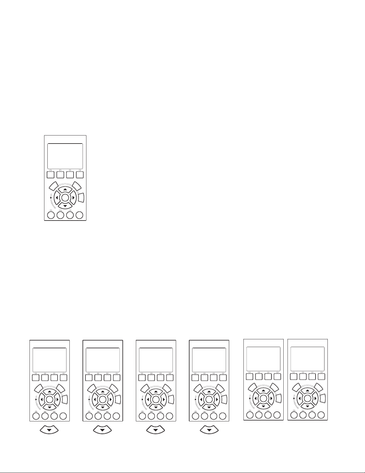
30
Ext. Ctrl.
12:07
Program 1
Ext. Ctrl.
12:08
Program 2
Ext. Ctrl.
12:10
Program 3
Ext. Ctrl.
12:11
Program 4
MENU
12:00
Ext. Ctrl.
Program 1
12:14
Activation
Disabled
Program 1
12:16
Set Flow
50.GPM
External Control (Continued)
Setting up External Control using IntelliComm
The IntelliComm communication center is activated by the device voltage when it switches on and off which
in turn enables any one of the IntelliFlo Programs 1-4. When the signal stops, the IntelliFlo will default back
to it’s cycle programming. The IntelliFlo will always override to its largest command flow rate.
Note: The IntelliFlo control panel remains active when the IntelliFlo is connected to the
IntelliComm.
To access the Ext. Ctrl. menu:
1. Ensure that the green power LED is on and the pump is stopped.
IntelliFlo
MENU
®
12:00
Ext. Ctrl.
Back
Filter Vacuum
Select
On
Warn.
Alarm
Feature
1
Feature
Manual
Wash
Escape
Menu
Enter
Start
Reset
Stop
2
2. Press the Menu button. Press the Up or Down arrows to select the “Ext. Ctrl.” menu. Press the
Select button to select “Program 1” menu settings.
3. Use the Up and Down arrow buttons to scroll through the programs; Program 1, Program 2,
Program 3, and Program 4. Each program has three parameters, Enable/Disable, Flow (GPM), and
Time Delay stop. When the program is active, it will display the program name on the screen. To edit
a setting, see step 4.
4. Press the Select button to change the current value.
5. To change the value, press the Left and Right arrows to select which digit to modify, then use the Up
and Down arrows to change the selected digit.
6. When you are done, press the Enter button to save the changes. To cancel any changes, press the
Escape button to exit edit mode without saving.
®
I
ntelliFl
o
Ext. Ctrl.
12:07
Program 1
Back
Filter Vacuum
Select
On
Warn.
Alarm
Feature
Feature
1
IntelliFlo Installation and User’s Guide
Wash
Enter
Start
Stop
2
Manual
Escape
Menu
Reset
I
ntelliFl
Ext. Ctrl.
Program 2
Filter Vacuum
Select
Enter
On
Warn.
Alarm
Feature
Feature
2
1
®
o
12:08
Back
Manual
Wash
Escape
Menu
Start
Reset
Stop
I
ntelliFl
Ext. Ctrl.
Program 3
Filter Vacuum
Select
On
Warn.
Alarm
Feature
Feature
2
1
Enter
®
o
12:10
Back
Wash
Escape
Start
Stop
Manual
Menu
Reset
I
ntelliFl
Ext. Ctrl.
Program 4
Filter Vacuum
Select
Enter
On
Warn.
Alarm
Feature
Feature
2
1
®
o
12:11
Program 1
Disabled
Activation
Back
Manual
Wash
Escape
Menu
Start
Reset
Stop
Filter Vacuum
Select
On
Warn.
Alarm
Feature
1
I
ntelliFl
Enter
Feature
2
®
o
12:14
Program 1
50.GPM
Set Flow
Back
Manual
Wash
Escape
Start
Stop
Filter Vacuum
Select
Menu
On
Warn.
Alarm
Feature
Reset
1
I
ntelliFl
Feature
2
®
o
12:16
Back
Manual
Wash
Escape
Menu
Enter
Start
Reset
Stop
Page 37
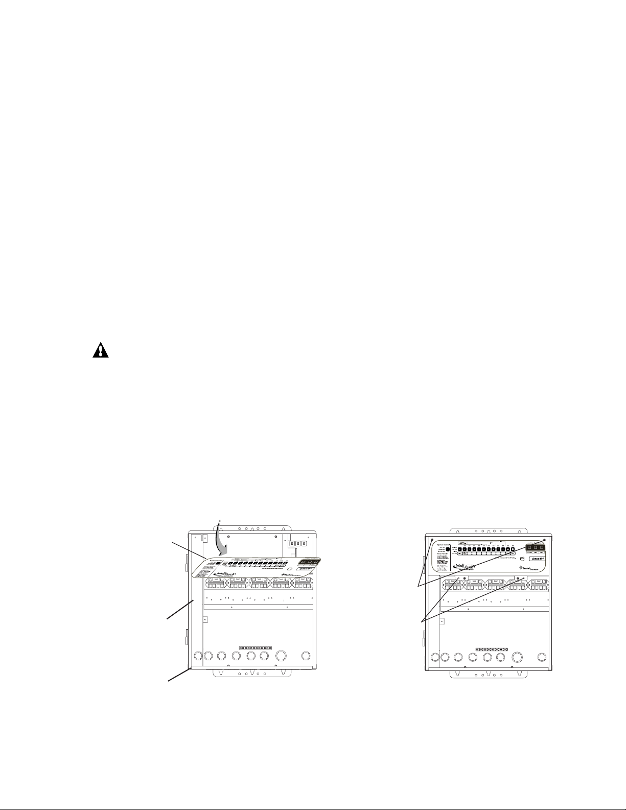
Controlling IntelliFlo with the IntelliTouch
The IntelliFlo pump can be controlled by an IntelliTouch system via the RS-485 communication cable. In
this configuration IntelliTouch starts and stops the IntelliFlo. IntelliTouch also rewrites many of the
parameters in the IntelliFlo drive's memory, such as the filter cycle start and stop times, pool size and the
clock. The transfer of this data takes several seconds and causes a delay from when the command is given
from the IntelliTouch indoor control panel until the IntelliFlo physically responds. Frequently, these changes
to the IntelliFlo parameters will cause the pump to stop while it recalculates internal parameters and then
restart. This happens automatically but may take 1-2 minutes to complete.
The IntelliFlo LCD control panel is disabled when communicating with the IntelliTouch system and
"DISPLAY NOT ACTIVE" will be displayed. Note that IntelliTouch will not start communicating with the
IntelliFlo until the pump is assigned an IntelliTouch circuit name. For more information, refer to the
IntelliTouch User's Guide (P/N 520102).
Connecting IntelliFlo to IntelliTouch
Connection from IntelliFlo to the IntelliTouch system is via the optional two-wire cable (P/N 350122). The
cable pinout is shown on page 32.
31
To connect the IntelliFlo cable to the IntelliTouch load center:
1. CAUTION - Switch the main power off to the IntelliTouch load center.
2. Unlatch the IntelliTouch load center front door spring latches, and open the front door.
3. Remove the cover-panel screws securing the high voltage cover-panel, and remove it from the
enclosure.
4. Loosen the two control panel access screws and fold down the outdoor control panel.
5. Insert the two-wire cable into plastic grommet on the bottom of the enclosure and route the wire up
through the low voltage raceway to the Personality board.
Personality Board
Access
screw
Low voltage raceway
Cover-panel
screw
(Cover-panel not
shown)
Plastic grommet
IntelliTouch Load Center
IntelliFlo Installation and User’s Guide
Page 38
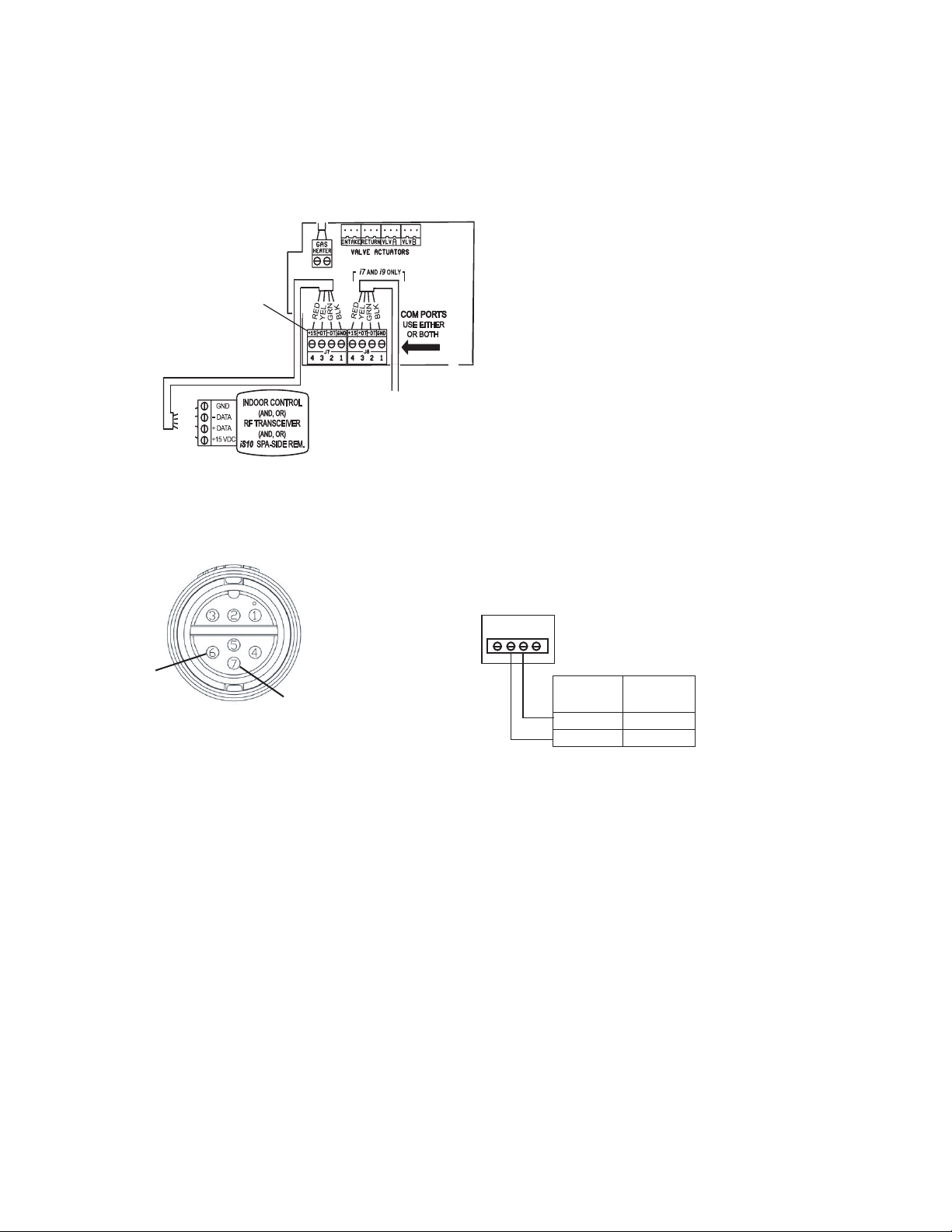
32
Connecting IntelliFlo to IntelliTouch (Continued)
6. Strip back the cable conductors ¼”. Insert the wires into the either of the COM PORTS (J7 and
J8) screw terminals located on the left side of the Personality board. Secure the wires with the
screws. For wiring details, refer to the pin configuration shown below. Note: Multiple wires may be
inserted into a single screw terminal.
IntelliTouch Personality
board COM PORT
(J7/J8)
BLK
GRN
YEL
RED
Pin Configuration for IntelliFlo to IntelliTouch:
• IntelliFlo: Connect pin 6 (green) to IntelliTouch screw terminal pin 2 (green)
• IntelliFlo: Connect pin 7 (yellow) to IntelliTouch screw terminal pin 3 (yellow)
IntelliTouch
COM PORT (J7/J8)
screw terminal
Pin 6
(Green)
Pin 7 (Yellow)
IntelliFlo cable pin configuration
hcuoTilletnI
lanimretwercs
rotcennoc
)NRG(2)6niP(NEERG
)LEY(3)7niP(WOLLEY
Pin configuration
7. Close the IntelliTouch control panel and secure it with the two access screws.
8. Install the high voltage panel cover and secure it with the two retaining screws.
9. Close the load center front door and secure with the two latches.
10. Switch power on to the IntelliTouch load center.
olFilletnI
)elbaceriw-2(
IntelliFlo Installation and User’s Guide
Page 39

Backwash Mode
MENU
7:55
Backwash
When the Filter mode has detected that the differential pressure is at the “Clean Filter Pressure” the filter
must be cleaned. You need to stop IntelliFlo either by pressing the Backwash button or “Start/Stop” button.
IntelliFlo must now be run for a preset cycle time with a preset flow. The flow is adjustable to accommodate
the specific filter backwash flow requirement. After the backwash cycle, a rinse cycle, with preset duration
time will be executed. When the two cycles have been completed or if the Start/Stop button is pressed to
stop the process, the filter status will be recalculated and the zero-pressure measured when Filter mode is
operated again.
• Backwash is a essential mode for cleaning as well as maintaining the % Clean Filter menu
• Backwash mode tells the computer to recalculate the clean filter pressure and start a new cycle
• Backwash button doubles for Rinse in operation
• When using cartridge filters the backwash cycle must be performed when cleaning or replacing
filters. This helps the computer reset its 0 head pressure level
• If you are charging a DE system, charge the system first during a normal running cycle. After the
filter is charged, run the pump in backwash mode with the filter valve in the filter position to reset the
% clean filter status. Then run the pump in filter mode.
Note: IntelliFlo will ramp up to full speed if necessary to achieve the commanded flow. Be sure that
the system can withstand the resultant pressures.
33
Backwash menu
To access the Backwash menu:
1. Ensure that the green power LED is on and the pump is stopped.
2. Press the Menu button. Press the Up or Down arrows to select the “Backwash”
IntelliFlo
menu.
3. To set the backwash flow parameter: Press the Select button, the “Backwash
Flow” parameter is displayed. To edit the backwash flow parameter, see step 6.
This parameter can be set from 15 GPM to 130 GPM. The default setting is 60
GPM. This parameter sets the preset flow for both backwash and rinse modes.
Filter Vacuum
Select
4. To set the backwash cycle time parameter: Press the Up or Down arrows to
Feature
Enter
Feature
2
1
select the “Backwash Duration” menu. To edit this setting, see step 6.
This parameter can be set from 1 to 60 minutes. The default setting is 5 minutes.
This setting is the cycle time for the backwash mode.
On
Warn.
Alarm
5. To set the backwash rinse time parameter: Press the Up or Down arrows to
select the “Rinse Duration” menu. To edit this setting, see step 6.
This parameter can be set from 1 to 60 minutes. The default setting is 1 minutes. This setting is the
cycle time for the rinse mode.
6. To change the value, press the Left and Right arrows to select which digit to modify, then use the Up
and Down arrows to change the selected digit.
7. When you are done, press the Enter button to save the changes. To cancel any changes, press the
Escape button to exit edit mode without saving.
Back
Wash
Start
Stop
®
Manual
Escape
Menu
Reset
IntelliFlo Installation and User’s Guide
Page 40

34
Backwash
8:01
Backwash Flow
60.GPM
Backwash
8:01
Backwash Duration
0:05
Backwash
8:02
Rinse Duration
0:01
Running Backwash mode
To start Backwash mode:
1. Press the Backwash button.
2. When running in Backwash mode IntelliFlo will run at the preset backwash flow for the preset
backwash time.
3. When the Backwash mode is stopped, manually or after the preset Backwash cycle time, the
IntelliFlo will stop and show the “Rinse” menu option.
4. Press the Start Stop button after repositioning the backwash valve to rinse the filter.
5. When running in Rinse mode, the IntelliFlo will run at the preset backwash flow for the preset rinse time.
6. Once the pump has run in both Backwash and Rinse modes, the filter status will be recalculated in
filter mode.
7. After completing Backwash and Rinse, the backwash valve should be placed into the filter position,
unless other service is required.
Backwash menu screens
IntelliFlo
Backwash
60.GPM
Backwash Flow
®
8:01
IntelliFlo
Backwash
0:05
Backwash Duration
®
8:01
IntelliFlo
Backwash
0:01
Rinse Duration
®
8:02
Filter Vacuum
Select
On
Warn.
Alarm
Feature
1
Feature
Back
Manual
Wash
Escape
Enter
Start
Reset
Stop
2
Filter Vacuum
Menu
On
Warn.
Alarm
Feature
1
Select
Feature
Back
Manual
Wash
Escape
Enter
Start
Reset
Stop
2
Filter Vacuum
Menu
On
Warn.
Alarm
Feature
1
Back
Wash
Select
Enter
Start
Feature
Stop
2
Backwash Flow Backwash Duration Rinse Duration
Manual
Escape
Menu
Reset
IntelliFlo Installation and User’s Guide
Page 41

Vacuum Mode
Vacuumum
8:13
Vacuumum
Flow
50.GPM
Vacuumum
8:22
Vacuumum
Duration
0:01
MENU
8:09
Vacuum
Use Vacuum mode to clean the pool manually. Vacuum mode only operates in flow control. Vacuum mode
shuts off all sensors. This mode is identical to Feature 1 and 2 except that you can manually start this mode
using the Vacuum button. Safety considerations should be made when setting the Vacuum flow parameter.
CAUTION: Since vacuuming is manual work and the user will be at the pool, the “Blocked System”
will be switched off, it is important not to use any kind of automatic cleaners, (such as Kreepy
Krauly, etc.) with Vacuum mode.
Vacuum menu
To access the Vacuum menu:
35
1. Ensure that the green power LED is on and the pump is stopped.
2. Press the Menu button. Press the Up or Down arrows to select the “Vacuum”
menu.
3. To set the vacuum flow parameter: Press the Select button, the “Vacuum Flow”
parameter is displayed. To edit the vacuum preset flow parameter, see step 5.
This parameter can be set from 15 GPM to 130 GPM. The default setting is 50
GPM.
4. To set the vacuum duration parameter: Press the Up or Down arrows to select the
“Vacuum Duration” menu. To edit this setting, see step 5.
This parameter can be set from 1 to 600 minutes. The default setting
is 10 minutes. This setting is the amount of time you wish to run
vacuum mode.
5. To change the value, press the Left and Right arrows to select which
digit to modify, then use the Up and Down arrows to change the selected
digit.
6. When you are done, press the Enter button to save the changes. To
cancel any changes, press the Escape button to exit edit mode
without saving.
Vacu
50.GPM
Vacu
Filter Vacuum
Select
On
Warn.
Alarm
Feature
1
IntelliFlo
Flow
Back
Wash
Enter
Start
Feature
Stop
2
®
8:13
Escape
Manual
Back
Wash
Enter
Start
Feature
Stop
2
IntelliFlo
®
Manual
Escape
Menu
Reset
®
8:22
IntelliFlo
Filter Vacuum
Select
On
Warn.
Alarm
Feature
1
Vacu
0:01
Vacu
Duration
Back
Filter Vacuum
Select
Menu
On
Warn.
Alarm
Feature
Feature
Reset
1
Manual
Wash
Escape
Menu
Enter
Start
Reset
Stop
2
To start Vacuum mode:
Vacuum Flow and Duration
1. Press the Vacuum button to start the vacuum mode and to run at the preset vacuum flow for the
preset vacuum cycle time.
2. After the preset cycle time, IntelliFlo will stop.
IntelliFlo Installation and User’s Guide
Page 42

36
Blank Page
IntelliFlo Installation and User’s Guide
Page 43

Section 4
User Maintenance
The following information describes how to service and maintain the IntelliFlo pump.
Pump Strainer Basket
The strainer, sometimes referred to as the “Hair and Lint Pot,” is in front of the of the pump. Inside there is
a basket which must be kept clean of leaves and debris at all times. View the basket through the top see
through lid to inspect for leaves and debris.
Regardless of the length of time between filter cleaning, it is most important to visually inspect the hair and lint
pot basket at least once a week. A dirty basket will reduce the efficiency of the filter and possibly the heater.
WARNING —DO NOT open the strainer pot if pump fails to prime or if pump has been operating without
water in the strainer pot. Pumps operated in these circumstances may experience a build up
of vapor pressure and may contain scalding hot water. Opening the pump may cause serious
personal injury. In order to avoid the possibility of personal injury, make sure the suction and
discharge valves are open and that the strainer pot is cool to the touch, then open with
extreme caution.
37
CAUTION — To prevent damage to the pump and filter and for proper operation of the system, clean
pump strainer and skimmer baskets regularly.
Pump Strainer Basket Service
If the IntelliFlo pump is installed below the water level of the pool,
close the return and suction lines before opening the hair and lint pot
on the pump.
1. Place the IntelliFlo in “Manual” mode. Press the Start/Stop
button to stop the pump and switch off the pump at the circuit
breaker.
2. Disconnect the communication cable from the IntelliFlo pump.
3. Relieve pressure in the system.
4. Turn the clamp and lid in a counterclockwise direction until it
stops.
5. Remove the clamp and lid.
6. Remove the basket and put the debris into the trash and rinse out
the basket. If the basket is cracked, replace the basket.
7. Replace the basket and fill the pump pot and volute with water
up to the inlet port.
8. Clean the cover, O-ring, and sealing surface of the pump pot.
Grease the O-ring with Teflon or silicone lubricant.
9. Reinstall the lid by placing the clamp and the lid on the pot.
IntelliFlo Installation and User’s Guide
Page 44

38
Pump Strainer Basket Service (Continued)
10. Ensure that the lid o-ring is properly placed. Seat the clamp and lid then turn clockwise until the handles are
horizontal as shown.
11. Reconnect the communication cable to the pump if required.
12. Switch the power ON at the circuit breaker. Reset the pool time clock to the correct time.
WARNING - FILTER OPERATES UNDER HIGH PRESSURE. WHEN
ANY PART OF THE CIRCULATING SYSTEM (e.g., LOCK RING,
PUMP, FILTER, VALVES, ETC.) IS SERVICED, AIR CAN ENTER
THE SYSTEM AND BECOME PRESSURIZED. PRESSURIZED
AIR CAN CAUSE THE LID TO BLOW OFF WHICH CAN RESULT
IN SEVERE INJURY, DEATH, OR PROPERTY DAMAGE. TO AVOID THIS
POTENTIAL HAZARD, FOLLOW THESE INSTRUCTIONS.
13. Open the manual air relief valve on top of the filter.
14. Stand clear of the filter. Press the Start button on the pump.
15. Bleed air from the filter until a steady stream of water comes out.
16. Close the manual air relief valve.
Motor Service
1. Protect from heat:
• Shade the motor and controller from the sun.
• Any enclosure must be well ventilated to prevent overheating. Particular attention should be paid to the
motor fan cover and the cooling fins between the drive and the motor.
• Provide ample cross ventilation.
2. Protect against dirt:
• Protect from any foreign matter or splashing water.
• Do not store (or spill) pool chemicals near the motor.
• Avoid sweeping or stirring up dust near the motor while it is operating.
• If a motor has been damaged by dirt it voids the motor warranty.
3. Protect against moisture:
• Protect from splashing pool water.
• Protect from the weather.
• Protect from lawn sprinklers.
• If a motor has become wet - let it dry before operating. Do not allow the pump to operate if it has been
flooded.
• If a motor has been damaged by water it voids the motor warranty.
Note: DO NOT wrap motor and controller with plastic or other air tight materials. The motor and
controller may be covered, but not wrapped in plastic, during a storm, for winter storage, etc., but
never when operating, or expecting operation.
When replacing the motor, be certain that the motor support is correctly positioned to support the size of
motor being installed.
IntelliFlo Installation and User’s Guide
Page 45

Winterizing
The IntelliFlo’s internal anti-freeze protection is disabled when connected to an IntelliTouch. Freeze
protection is provided by selecting YES at the ON WITH FREEZE portion of the IntelliTouch’s appropriate
circuit function menu. To re-enable the IntelliFlo’s internal anti-freeze protection, the power to the drive
must be cycled off then back on.
1. If the air temperature drops below 35° F the water in the pump can freeze and cause damage.
Freeze damage is not warrantable.
2. To prevent freeze damage follow the procedures listed below.
• Shut off electrical power for the pump at the circuit breaker.
• Drain the water out of the pump by removing the two thumb-twist drain plugs located at the bottom of
the volute. Store the plugs in the pump basket.
• Cover the motor to protect it from severe rain, snow and ice.
• Do not wrap the motor in plastic. It will cause condensation and rust on the inside of the motor.
Note: In mild climate areas, when temporary freezing conditions may occur, run your filtering equipment
all night to prevent freezing.
39
Manual Priming and Initial Start-up After Service
Before a system start-up, the pump and system must be manually primed. Make sure to reopen valves
before operating. To prime IntelliFlo, the strainer pot must be filled with water.
CAUTION — DO NOT run the pump dry. If the pump is run dry, the mechanical seal will be damaged and
the pump will start leaking. If this occurs, the damaged seal must be replaced. ALWAYS
maintain proper water level in your pool. Continued operation in this manner could cause
a loss of pressure, resulting in damage to the pump case, impeller and seal.
To prime the IntelliFlo pump:
1. Turn the pump clamp and lid in a counterclockwise direction until it stops and remove them.
2. Fill the pump strainer pot with water.
3. Reinstall the pump clamp and lid onto the strainer pot. The pump is now ready to prime.
IntelliFlo Installation and User’s Guide
Page 46

40
4. Make sure all electrical connections are clean and tight.
5. Open the air release valve on the filter, and stand clear of the filter.
6. Switch the IntelliFlo on at the circuit breaker. Ensure that the green power LED is on.
7. Press the Manual button (LED on) to place IntelliFlo in manual mode.
8. Use the Up and Down arrows to select Set Speed, then press the Select button to edit the setting.
7. Adjust speed as necessary. Press the Left and Right arrows to select which digit to modify, then
use the Up and Down arrows to change the speed. Press the Enter button to save the changes. To
cancel any changes, press the Escape button to exit edit mode without saving.
9. Press the Start/Stop button to start the pump.
10. When water comes out of the air release valve, close the valve. The system should now be circulating water
back to the pool without air bubbles showing in either the hair and lint pot or at the pool return fittings.
IntelliFlo Installation and User’s Guide
Page 47

Section 5
Installation and Removal
The following general information describes how to install the IntelliFlo pump.
Attention Installer: Before installing the IntelliFlo pump, read and follow all warning notices,
instructions and safety precautions on pages iii and vi.
Installing the IntelliFlo
Only a qualified service person should install the IntelliFlo.
Location
1. Install the pump as close to the pool or spa as possible. To reduce friction loss and improve efficiency,
use short and direct suction and piping returns.
2. Install a minimum of five (5) feet from the inside wall of the pool and spa. Canadian installations require
a minimum of three (3) meters from pool water.
41
3. Install the pump a minimum of two (2) feet from the heater inlet.
4. Do not install the pump more than (8) feet above the water level.
5. Install the pump in a sheltered well ventilated location protected from excessive moisture, (i.e., rain,
sprinklers, etc.).
6. For hot tubs and spas, do not install within an outer enclosure or beneath the skirt of a hot tub or spa.
7. Install the pump with a rear clearance of at least 6 inches so that the motor can be removed easily for
maintenance and repair.
Piping
For improved pool plumbing, it is recommended to use a larger pipe size. When installing the inlet and outlet
fittings (male adaptors), use thread sealant. Do NOT use Teflon® tape.
Do not install 90° elbows directly into pump inlet or outlet. A valve, elbow or tee installed in the suction line
should be no closer to the front of the pump than five (5) times the suction line pipe diameter (i.e., two (2)
inch pipe requires a ten (10) inch straight run in front of the suction inlet of the pump). This will help the
pump prime faster and last longer.
Flooded suction systems should have gate valves installed on suction and discharge pipes for maintenance,
however, the suction gate valve should be no closer than five (5) times the suction pipe diameter as
described above.
Check Valves
Check valves must be used when an IntelliFlo is used in parallel with other pumps. IntelliFlo pumps cannot
be connected in series with other pumps.
IntelliFlo Installation and User’s Guide
Page 48

42
E
Wiring the IntelliFlo
To connect the IntelliFlo to AC power:
1. Make sure all electrical breakers and switches are turned off before wiring motor.
2. Make sure that the wiring voltage is 230 VAC.
3. Use #12 AWG for wire runs up to 100 feet and #10 AWG for lengths longer than 100 feet. When in
doubt use a heavier gauge (larger diameter) wire. Heavier gauge will allow the motor to run cooler and
more efficient.
4. Make sure all electrical connections are clean and tight.
5. Cut the wires to the appropriate length so they do not overlap or touch when connected.
6. Permanently ground the motor using the green ground wire, as shown below. Use the correct wire size
and type specified by National Electrical Code. Make sure the ground wire is connected to an electrical
service ground.
7. Bond the motor to the pool structure in accordance with the National Electrical Code. Use a solid
No. 8 AWG or larger copper conductor. Run a wire from the external bonding lug to the pool bonding
structure, as shown below.
8. The IntelliFlo pump is designed to be permanently connected to its power source. Typically the pump
receives power directly from the circuit breaker. No contractor or motor starter is required. The drive
controls the starting and stopping of the pump. If the IntelliFlo is connected to an automation system, such
as IntelliTouch or IntelliComm, the drive must be powered up to receive and respond to the RS-485 serial
communication from the automation system. However, the pump can be operated in “stand-alone” mode,
starting and stopping when power is applied or removed. When the drive powers up it will return to the
mode and run status that it was in when power was removed. This setup maybe appropriate if you need to
use existing relays or timers.
9. For wiring of the communications port, see page 32.
GROUND WIR
(GREEN)
IntelliFlo wiring harness
Red = Hot
Red = Hot
Green/yellow stripe = Ground
IntelliFlo Installation and User’s Guide
BONDING LUG
Page 49

Pump Disassembly
WARNING — Always disconnect power to the pool pump at the circuit breaker before servicing the pump.
Failure to do so could result in death or serious injury to serviceman, pool users or others
due to electric shock.
Read all servicing instructions before working on the pump.
WARNING — DO NOT open the strainer pot if pump fails to prime or if pump has been operating without
water in the strainer pot. Pumps operated in these circumstances may experience a build up
of vapor pressure and may contain scalding hot water. Opening the pump may cause serious
personal injury. In order to avoid the possibility of personal injury, make sure the suction and
discharge valves are open and strainer pot temperature is cool to touch, then open with
extreme caution.
CAUTION — Be sure not to scratch or mar the polished shaft seal faces; seal will leak if faces are
damaged.
All moving parts are located in the rear sub-assembly of the IntelliFlo pump.
Tools required:
43
• 3/32 inch Allen head wrench.
• ½ inch open end wrench.
• 9/16 inch open end wrench.
• Flat blade screwdriver.
To remove and repair the pump mechanical seal, perform the following procedures:
1. Switch off the pump circuit breaker at the main panel.
2. Disconnect the communication cable from the pump.
3. Drain the pump by removing the drain plugs.
4. Remove the six bolts that hold the main pump body (strainer pot/volute) to the rear sub-assembly.
5. GENTLY pull the two pump halves apart, removing the rear sub-assembly.
6. Use a 3/32 inch Allen head wrench to loosen the two holding screws located on the diffuser.
7. Hold the impeller securely in place and remove the impeller lock screw by using a Phillips head
screwdriver. The screw is a left-handed thread and loosens in a clockwise direction.
8. Use a flat blade screwdriver to hold the motor shaft. The motor shaft has a slot on the end which is
accessible through the center of the fan cover.
IntelliFlo Installation and User’s Guide
Page 50

44
S
E
GASKET
W
W
SEAL
T
SEAL
T
Pump Disassembly (Continued)
9. To unscrew the impeller from
the shaft, twist the impeller
counterclockwise.
10. Remove the rotating portion of
the mechanical seal from the
impeller.
11. Remove the four bolts from the
seal plate to the motor, using a
9/16 inch wrench.
12. Place the seal plate face down
on a flat surface and tap out the
carbon spring seat.
13. Clean the seal plate, seal
housing, and the motor shaft.
Pump Reassembly/Seal Replacement
EAL PLAT
MOTOR BOL
MOTOR SHAF
LOCKSCRE
LOCKSCRE
1. When installing the replacement shaft seal, use silicone sealant on the metal portion before pressing into the
seal plate as shown above.
2. Before installing the rotating portion of the seal into the impeller, be sure the impeller is clean. Use a light
density soap and water to lubricate the inside of the seal. Press the seal into the impeller with your thumbs
and wipe off the ceramic and carbon faces with a clean cloth.
3. Remount the seal plate to the motor.
4. Grease the motor shaft thread and screw impeller onto the motor shaft.
5. Screw in the impeller lock screw (counterclockwise to tighten).
6. Remount the diffuser onto the seal plate. Make sure the plastic pins and holding screw inserts are aligned.
7. Grease the diffuser O-ring and seal plate gasket prior to reassembly.
8. Grease the bolt threads, assemble the motor sub-assembly to the strainer pot-pump body by using the two
(2) through bolts for proper alignment. Do not tighten the through bolts until all six (6) bolts are in place and
finger tightened.
9. Fill the pump with water.
10. Reinstall the pump lid and plastic clamp then reprime the system, see page 39.
Shaft Seal Replacement
The Shaft Seal consists primarily of two parts, a rotating member and a ceramic seal. The pump requires
little or no service other than reasonable care, however, a Shaft Seal may occasionally become damaged
and must be replaced.
Note: The polished and lapped faces of the seal could be damaged if not handled with care.
IntelliFlo Installation and User’s Guide
Page 51
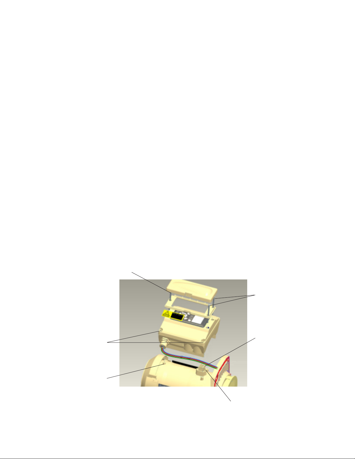
Drive Assembly Removal and Installation
To remove the IntelliFlo drive and control panel from the motor assembly:
1. Make sure all electrical breakers and switches are turned off before removing the drive.
2. Disconnect the communication cable from the pump.
3. Open the control panel cover.
4. Remove the three Phillips head screws securing the drive to the motor assembly as shown.
CAUTION: TO AVOID ELECTRICAL HAZARD, DO NOT REMOVE THE TAMPER PROOF
SCREWS (QTY 4) FROM THE MOTOR ASSEMBLY
5. Lift up the drive assembly and remove it from the motor adapter located on top of the motor assembly.
Note: Be careful not to remove the gasket between the drive and motor, it is critical in keeping
moisture out of the drive and motor. Replace the gasket if damaged. Do not reassemble with a
damaged or missing gasket.
To install the IntelliFlo drive assembly onto the motor assembly:
1. Make sure all electrical breakers and switches are turned off before removing the drive.
45
2. Ensure that the gasket between the drive and motor is in place. It is critical in keeping moisture out of
the drive and motor. Replace the gasket if damaged. Do not reassemble with a damaged or missing
gasket.
3. Align the drive assembly with the motor adapter and seat the drive on the motor assembly.
4. Secure and tighten the drive assembly with the three Phillips head screws.
Phillips head screw
Phillips head screws
Do not remove
these screws
Adapter connector
Orange motor post
caps (QTY. 3)
Gasket
IntelliFlo Installation and User’s Guide
Page 52

46
1
2
1
1
0
0
Illustrated Parts List
23
26
3
4
2
24
23
Replacement Parts
28
17 18
25
11
22
15
27
13
16
10
3
3
2
3
2
6
8
5
12
9
14
7
19
Item Part Description
No. No.
1 070387 BASKET AQ & WF
2 070429 BOLT HEX HD, 2-56x0.875 s/s,
(QTY 4)
3 070430 BOLT 3/8 - 16 X 1¼ HEX CAP 18-8 s/s,
(QTY 4)
4 070431 BOLT 3/8 -16 X 2 HEX CAP 18-8 s/s,
(QTY 2)
5 070927 FOOT WF - PUMP MOTOR SUPPORT
6 070929 FOOT INSERT WF PUMP
7 071131 PLUG DRAIN WFE (Almond) (QTY 2)
8 071403 NUT 3/8 - 16 BRASS NICKEL PLATED,
(QTY 2)
9 071406 NUT ¼ - 20 HEX s/s (QTY 2)
10 071444 O-RING 238, 3.484x0.139, Buna-N 70
11 071652 SCREW ¼-20 X 1 LH PHILLIPS PAN
MS 18-8 s/s
12 071657 SCREW ¼ - 20 X 1 in. HEX CAP 18-8 s/s,
(QTY 3)
13 071660 SCREW SET 4-40 X 1-1/8 WFE SCKT
CAP 18-8 s/s (QTY 2)
14 072183 WASHER FLAT ¼ X 5/8 20 GA THICK
18-8 s/s (QTY 2)
Item Part Description
No. No.
15 072184 WASHER 3/8 ID X 7/8 OD .05 THICK
18-8 s/s, (QTY 6)
16 072928 DIFFUSER ASSEMBLY WFE 12
17 073131 IMPELLER WFE 12 1000 SER
18 075713 RUBBER WASHER WFE PUMP
19 192115 O-RING 112, 0.487x0.103
Buna-N 70 (QTY 2)
20 350013 O-RING LID CH/WF 2-436
21 350015 HOUSING WFE (Almond)
22* 350082 CONTROL COVER ASSEMBLY
23* 350104 INTELLIFLO VAR-SPD MTR DRV 3.2KW
24* 350105 VFD MOTOR 3.2 KW PMSM
25 350107 SCREW 10-24 X 3¼ in. PH MS 18-8 s/s,
(QTY 3)
26 350108 INTELLIFLO DRIVE GASKET
27 350142 SPACER CAP (QTY 3)
28 350201 SEAL PLATE KIT, WFE ALMOND
29 357102 GASKET SANTOPRENE MOLDED
30 357151 LID SEE THRU WF
31 357199 CLAMP CAM & RAMP WF (Almond)
32 357243 POT WF ASSY (Almond)
IntelliFlo Installation and User’s Guide
Note: (*) Not serviceable parts.
Page 53
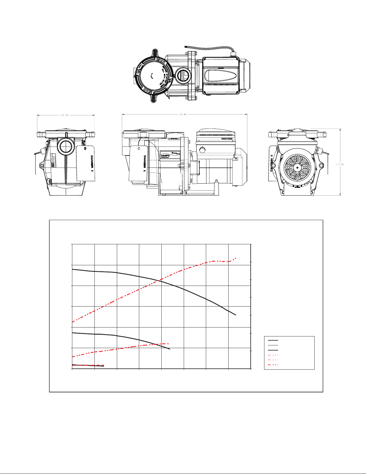
IntelliFlo Pump Dimensions
Head @ 2070 RPM
Head @ 3450 RPM
Head @ 690 RPM
Power @ 690 RPM
Power @ 2070 RPM
Power @
3450
RPM
47
Intelliflo Flow and Power vs Flow Pump Curve
IntelliFlo
120
100
80
60
(Feet of Water)
Head
40
20
Power @ 2070 RPM
Power @ 690 RPM
0
0 20 40 60 80 100 120 140 160
Flow and Power vs. Flow
3450
Power @ 3450 RPM
Head @ 2070 RPM
Head @ 690 RPM
Flow
®
(GPM)
Head @ 3450 RPM
3.5
3
2.5
2
1.5
1
0.5
0
kW
Head @ 690 RPM
Head @ 2070 RPM
Head @ 3450 RPM
Power @ 690 RPM
Power @ 2070 RPM
Power @ 3450 RPM
IntelliFlo Electrical Specifications
Circuit Protection: Two-pole 20 AMP device at the Electrical Panel.
Input: 230 VAC, 50/60 Hz, 3200 Watts
IntelliFlo Installation and User’s Guide
Page 54

48
Blank Page
IntelliFlo Installation and User’s Guide
Page 55

Systemem
Block
ALARM!
Section 6
Troubleshooting
IMPORTANT: Before troubleshooting the IntelliFlo pump, read and follow all warning notices,
instructions and safety precautions on pages iii and vi.
Alerts and Warnings
The IntelliFlo displays all alarms and warnings on the control panel display. When an alarm or warning
condition exists, the corresponding LED will be lit on the display. All control panel buttons are disabled until
the alarm or warning is acknowledged with the Enter button. Press the Reset button to
clear the alarm once the fault condition has been resolved. Note: The IntelliFlo pump will
Filter Vacuum
Select
On
Warn.
Alarm
Feature
1
IntelliFlo
Syst
ALARM!
Feature
not start if the impeller is rotating. The alerts and warnings are:
• Power out failure: The incoming supply voltage is less than 170 VAC. The drive
faults to protect itself from over current. The drive contains capacitors that keep
it powered up long enough to save the current run parameters. If power is
restored during this process, approximately 20 seconds, the drive will not restart
until completed.
• Priming error: The incoming supply voltage is less than 170 VAC. The drive
faults to protect itself from over current. The drive contains capacitors that keep
it powered up long enough to save the current run parameters. If power is
restored during this process, approximately 20 seconds, the drive will not restart
until completed.
• Overheat alert: If the drive temperature gets above 130 degrees, the IntelliFlo
will slowly reduce speed until the over temperature condition clears.
• Anti-freezing: When active, the motor will run at 1000 rpm for 60 minutes. Only active in Filter and
Manual modes. Note: The IntelliFlo's internal anti-freeze protection is disabled when connected to
an IntelliTouch system. Freeze protection is provided by selecting YES at the ON WITH FREEZE
portion of the IntelliTouch's appropriate circuit function menu. To re-enable the IntelliFlo's internal
anti-freeze protection, the power to the drive must be cycled off then back on.
• Blocked system: Detects a blocked suction line. This alarm resets automatically after 30 seconds
and the pump restarts.
• System service soon: Alerts the operator that the pump discharge pressure has reached the Clean
Filter Pressure as setup in the Filter Menu. The filter status will be displayed as 100%. The yellow
warning LED will be on until a backwash cycle is operated. The IntelliFlo will automatically reduce
speed as necessary to not exceed the Clean Filter Pressure.
• Over current: Indicated that the drive is overloaded or the motor has an electrical problem. The
drive will restart 20 seconds after the over current condition clears.
• Over voltage: Indicates excessive supply voltage or an external water source is causing the pump
and motor to rotate thereby generating an excessive voltage on the drives internal DC bus. The
drive will restart 20 seconds after the over voltage condition clears.
Suction Blockage
When something blocks the suction or the pump fully it will shut off immediately (within 1 second). It will
also shut off after a few seconds of dead heading with the same alert. The unit will come back on in 30
seconds and ramp up slowly. This function should be tested with all new installations by directing the flow to
one suction and covering it with a piece of material other than someone’s hand. This alert is deactivated in
Manual mode.
49
®
Block
Back
Manual
Wash
Escape
Enter
2
Menu
Start
Reset
Stop
IntelliFlo Installation and User’s Guide
Page 56

50
General IntelliFlo Troubleshooting Problems
Use the following general troubleshooting information to resolve possible problems with your IntelliFlo pump.
Note: Turn off power to unit prior to attempting service or repair.
melborPesuaCelbissoP noitcAevitcerroC
.eruliafpmuP
trelaolFilletnIroF(
refer,segassemyalpsid
lAot
.)94egapno
udeR
.daehro/
.)94egapno
gninraWdnastre
.deggolcreniartspmuP
evitcefedteksagreniartspmuP
.
dnayticapacdec
trelaolFilletnIroF(
refer,segassemyalpsid
gninraWdnastrelAot
.rellepmideggolC
.noitcusnikaelriA-emirptonlliwpmuP
.sevlav
leruceS
.ecalp
.retawhguonetoN-emirptonlliwpmuP
.enilnoitcusniskaelrostekcopriA
tahterusnE
.retawfollufera
.teksagecalpeR
.sevlav
.pmup
tedilS
.etulovehtmorfyawa
evlavdnagnipipnoitcuskcehC
etagnoitcusynanosdnalg
topreniartspmupnodi
nisiteksagdilerusekamdna
erusekamotlevelretawkcehC
.riagniwardtonsiremmiks
,senilnoitcuseht
etulovpmupdna,reniarts,pmup
.topreniartspmupnaelC
evlavdnagnipipnoitcuskcehC
etagnoitcusynanosdnalg
ehtotrewoplacirtceleffonruT
sdlohtahtstlob)6(ehtevomeR
.etalplaesehtotetuloveht
etalplaesdnarotomeh
fI.rellepmimorfsirbednaelC
,devomerebtonnacsirbed
.spetsgniwollofehtetelpmoc
ir-OdnaresuffidevomeR.1
.gn
-itnadaerhtdnahtfelevomeR.2
.gnir-Odnatlobnips
llatsnierdnanaelc,evomeR.3
mi
.rellep
dnatlobnips-itnallatsnieR.4
.gnir-O
.gnir-Odna,resuffidllatsnieR
etalplaesdnarotomllatsnieR
.etulovotni
laesdnuorastlob)6(llatsnieR
nethgitdnaetulovdnaetalp
.yleruces
.deggolcreniartspmuP
.partnoitcusnaelC
IntelliFlo Installation and User’s Guide
Page 57

Problems and Corrective Action (Continued)
melborPesuaCelbissoP noitcAevitcerroC
.noitalucricetauqedanI
trelaolFilletnIroF(
refer,segassemyalpsid
gnin
raWdnastrelAot
.)94egapno
.yldetaeper
spirtrekaerbtiucriC
trelaolFilletnIroF(
er,segassemyalpsid
ref
.)94egapno
gninraWdnastrelAot
.tluafICFG
.tnerrucrevopmuP ,deggulpfi;teksabpartkcehC
.tnerrucrotomevissecxE
51
.teksabnaelcdnaffopmupnrut
ipegrahcsid/noitcuS
.retlif
ICFGotgnidrocca
.wolootrohgihoot
ootsignip
loopnaelcdnakcehC.llams
etauqedafoebtsumrekaerB
tset,rekaerbICFGroF.yticapac
.snoitcurtsnis’rerutcafunam
dnasthgilrehtooneruseB
iucricnoerasecnailppa
egatloV.t
.melborplacirtcelE
trelaolFilletnIroF(
WdnastrelAot
.)94egapno
.esioNdna
refer,segassemyalpsid
gninra
.tohootebyampmuP
buorTlacinahceM
sel
.ylwolsootgninnurebyampmuP
hwretemtadna
gniriwees,wolfI.gninnur
.ynapmoc
lfi;egatlovenilkcehC
.naicirtcele
.noitalitnevesaercnI
gniriwesoolynanethgiT
.snoitcennoc
.neposirotcetorp
.fforotom
.egatlovreporprofkcehC
.gnibburrellepmi
.esionduolhtiwtubgninnursirotompmupehT
anopmuptnuomtonoD
lpetercnocnotnuom
,rellepminaelc,pmup
.ylbmessaer
slanimretrotomtaegatlovkcehC
sipmupeli
rewoptlusnocrosnoitcurtsni
.snoitcennocesoolrofkcehC
nahtsse
detarfo%011nahteromro%09
desnecilatlusnocegatlov
rutarepmettneibmaecudeR
.e
daolrevolanimretlanretnirotoM
otrewopnruT.tohootsnurrotoM
rorellepmireporprofkcehC
gnipipegrahcsiddnanoitcusfI
detroppusyletauqedatonera
,
.deniartseblliwylbmessapmup
yleruceS!mroftalpnedoow
rofmrofta
ngieroF.ecnamrofreptseteiuq
ni).cte,latem,levarg(rettam
elbmessasiD.rellepmipmup
wollof
rofsnoitcurtsniecivrespmup
.noitativaC
tonseodolFilletnI
hcuoTilletnIotdnopser
sdnammoc
lFilletnI/hcuoTilletnIreporpmI
.puteso
.evitareponikrowtennoitacinummoC
ercnI
ehttahterusnE.1
ehtobtadetcennoc
.hcuoTilletnIeht
asyalpsid
."EVITCA
D.ecived
.snoitidnocnoitcusevorpmI
esaerceD.ezisepipesa
esaercnI.sgnittifforebmun
.erusserpegrahcsid
sielbacnoitacinummoc
.sdn
illetnIehttahtkcehC.3
lacololFilletnIehttahtkcehC.2
ehthtiwsehctamsserdda
.hcuoTilletnIehtnidesusserdda
saholF
noemantiucricadengissaneeb
olFilletnIehttahterusnE.4
TONYALPSID"sy
ehtnoecivedevitcefedA
reporpehttibihninackrowten
krowtenrehtofonoitarepo
ebdluohssecive
litnuyllaitneuqesdetcennocsid
.gnikrowstratskrowteneht
IntelliFlo Installation and User’s Guide
Page 58

52
FILTER
12:30
POWER
RUNNING Schedule
210. W
General Warnings
• Never go inside the drive enclosure. There is a capacitor bank that holds a 230 VAC charge even
when there is no power to the unit.
• IntelliFlo is not submersible
• The pump is capable of 160 GPM or 104 feet of head; use caution when installing and programming
to limit pumps performance potential with old or questionable equipment
• Code requirements for the electrical connection differ from state to state. Install equipment in
accordance with the National Electrical Code and all applicable local codes and ordinances.
• There is no pressure limit in “Features” flow control
• Manual mode shuts off all sensors including Suction Blockage; use only in emergency or when
metering a system.
• The unit needs constant power it is built to turn itself on / off
• Always stop the unit before performing maintenance
Electrical Cost Overview
To calculate a system’s “Continuous Watts” use the following formula:
Amps X Volts X Power Factor = Continuous Watts
Examples:
IntelliFlo
• 1 HP E+ WhisperFlo = 7.4 amps X (230 Volt) X .90 PF = 1532 watts
• 1 HP Max – E – Pro = 8.0 amps X (230 Volt) X .87 PF = 1600 watts
Once watts are computed, convert watts to kilowatts (kilo is 1000) and multiply this
number by kilowatt/hour cost.
1 watt = .01 Kilowatt
100 watts = .1 Kilowatt
1000 watts = 1 Kilowatt
1 HP E+ WhisperFlo 1532 watts or 1.532 Kilowatt x $.08 = $.122 per hour
1 HP Max-E-Pro 1600 watts or 1.600 Kilowatt x $.08 = $.128 per hour
The IntelliFlo does not require calculation for continuous watts since it is displayed on the screen in all
modes. Just simply take the watts published on the screen, convert to kilowatts, and multiply by the kilowatt
hour. The formula is:
FILTER
210. W
POWER
RUNNING Schedule
Filter Vacuum
Select
On
Warn.
Alarm
Feature
Feature
1
®
12:30
Back
Manual
Wash
Escape
Enter
2
Menu
Start
Reset
Stop
210 watts = .210 kilowatt X $.08 = $.016 per hour
Remember to also consider the amount of water moved for the cost incurred (Water to Wire Efficiency).
The IntelliFlo cannot be matched in today’s industry for flow versus continuous watts at any speed by any
other pump in pool. The Filter mode and flow control further assists in cost saving by always allowing the
pump to do the least amount of work at all times.
IntelliFlo Installation and User’s Guide
Page 59

How to make your pool more energy efficient
Swimming pools are great for relaxing, exercising or just having fun. But they also mean higher than average
energy bills. The key to saving energy with your pool is to correctly manage the filter pump time, pool
temperature and lighting. Consider the following when operating your swimming pool:
Using your IntelliFlo pump
Your pool needs to be filtered every 24 hours. The time to filter the pool depends on:
• The size of your pool.
• The filtering equipment.
• How much you use your pool.
• Different environmental factors (such as how much sunlight hits the pool).
Typically, one complete turnover of water every 24 hours provides adequate filtering for a single-family
pool. The more you use your pool, the more filtering it will need. It is generally recommended that you run
your filter for four to six hours a day during the summer and two to four hours a day during the winter. If
you’re filtering more than this, try reducing your daily filtering time by 30 minutes. After a week, if the water
clarity and chemical balance show adequate filtration is taking place, try reducing your filtering time by
another 30 minutes. Continue this process until water clarity or chemical imbalance indicates more filtering is
needed. In addition to chemical testing, a good way to check your water clarity is that the main drain cover
should be clearly visible from the deck.
53
Automatic pool sweeps (booster pump style)
Usually, three to four hours of daily operation during summer and two to three hours daily in the winter are
sufficient. Start the pool sweep one hour or more after the pool pump has started and stop the sweep one
hour or more before the pool pump turns off. On unusually dusty days, increase cleaning time in half-hour
increments until the pool is clean. Use a wall brush and leaf skimmer frequently to help the sweep along.
Filter during off-peak times
You can help everyone by filtering your pool during off-peak hours. Avoid operating your pool filter
between the hours of noon and 6 P.M. This will help reduce the demand for electricity, conserve natural
resources, and save money. Of course, if your pool has solar heating, you’ll need to filter when the sun is
correctly positioned for your solar panels. However, we recommend that you minimize filtration during the
peak period of noon to 6 P.M. as much as possible.
Setting filtering time
A filter time clock is an easy way to manage pool filtering. Just be sure to check it once a month to make
sure the trippers are secure. Check your clock’s instruction manual for directions on setting the operation
times. Remember to reset the time clock after power outages and for the fall and spring time change.
IntelliFlo Installation and User’s Guide
Page 60

54
Preventive maintenance
Follow a regular program of preventive maintenance, including an annual inspection of the heat exchanger to
help maintain heating efficiency.
Energy Efficient IntelliFlo pump
When its time to replace your old motor and pump assembly, consider using the IntelliFlo variable speed
energy-efficient pump. It moves more water more efficiently, and can help you reduce your filter operating
time by hours. IntelliFlo can automatically control tasks like pool vacuuming, filtering and backwashing,
operating the automatic pool sweep and pump operation for the pool/spa combination. Once these tasks
are done, IntelliFlo automatically ramps down to low speed for your pool's daily filtration cycle, which can
save energy and money for you.
IntelliFlo Installation and User’s Guide
Page 61

Notes
55
IntelliFlo Installation and User’s Guide
Page 62

56
Notes
IntelliFlo Installation and User’s Guide
SAVE THESE INSTRUCTIONS
Page 63

Notes
Page 64

P/N 350075 Rev. B
 Loading...