

ULTRATEMP ETi
HYBRID HEATER
™
ENGLISH
ENGLISH
ESPAÑOL
FRANÇAIS
IMPORTANT SAFE T Y INSTRUCTIONS
RE AD AND FOLLOW ALL INSTRUCTIONS
SAVE THESE INSTRUCTIONS
INSTALLATION AND
USER’S GUIDE

i
CUSTOMER SERVICE / TECHNICAL SUPPORT
If you have questions about ordering Pentair Aquatic Systems, (“Pentair”) replacement parts, and pool products,
please use the following contact information:
Customer Service (8 A.M. to 4:30 P.M. — Eastern
and Pacific Times)
Phone: (800) 831-7133
Fax: (800) 284-4151
Web site
Visit www.pentairpool.com or www.staritepool.com to
find information about Pentair products.
TABLE OF CONTENTS
Important Warning and Safety Instructions .......
General Information ..............................................
Heater Introduction
Installation Requirements
General Installation Information
General Features
Positioning the Heater ..........................................
Materials Needed for Installation
Roof Run-off
Lawn Sprinklers
Equipment Pad
Recommended Clearances
Flue Gas Condensation Management
Preventative Maintenance
Condensate Cartridge Service
Installation .............................................................
Anchor Clamp Installation
System Layout
Internal Automatic Flow Control Valve
Water Connections and Plumbing
Heat Pump Drainage Connection
Isolation and Check Valves
Manual Bypass Valve
Pressure Relief Valve (PRV)
Multi-Heater Installations
Solar Installations
Water Pressure Switch Adjustment
Gas Connections
Gas Line Installation
Checking Gas Pressure Through Gas
Control Valve
Sediment Traps
Gas Pressure Testing
Electrical Connections and Wiring
Wiring Diagram - Input
Wiring Diagram - Output
Connecting to an Automation System ................
Remote Operation
Relay Remote Controls
Connecting to EasyTouch via Heater Spade
Terminals
Connecting to EasyTouch via RS-485 Connector
Pin Configuration for Heater Control Board
to EasyTouch
Connecting EasyTouch to the Heater
Operating the Heater ............................................
Swimming Pool Energy Saving Tips
Control Panel Overview
Sequence of Operation
Pre-Startup
P/N 475922 Rev. A 5/18/18
Technical Support
Sanford, North Carolina (8 A.M. to 4:30 P.M. ET)
Phone: (919) 566-8000
Fax: (919) 566-8920
Moorpark, California (8 A.M. to 4:30 P.M. PT)
Phone: (805) 553-5000 (Ext. 5591)
Fax: (805) 553-5515
ii
1
1
1
1
1
2
2
2
2
3
3
5
5
5
6
6
6
7
7
7
8
8
8
9
10
10
11
11
12
12
12
13
14
15
16
16
16
17
18
19
19
20
20
20
21
21
Basic Operating Instructions
Turning Off Gas to the Heater
Safety Controls
Air Flow Switch (AFS)
Water Pressure Switch (WPS)
High Limit Switch (HLS) and Automatic Gas
Shut-off Switch (AGS)
Stack Flue Sensor (SFS)
Thermal Fuse (TF)
Float Switch (CFS)
Ignition Module Operation
Operator Menu Tree Guide and Navigation
Using the Operator Menus
Starting and Stopping the Heater
Changing the Set Point
Efficiency Mode Selection
Heater Timer
Remote Mode - Relay
Remote Mode - RS-485 (Serial Cable)
Remote Mode - IntelliFlo
Timers and Delays
Control Panel Alarm Messages
Service Menu Tree Guide and Navigation
Using the Service Menus
Eco-Time
Boost Temperature
Setting Temperature Scale
Set Water Temperature Offset
Defrost Cycle
Run Time Counters
Locking the Control Panel
Maintenance ........................................................
Water Chemistry
Total Alkalinity
Balancing pH
Disinfectant Residual
General Maintenance
Condensate Drainage
Winterizing
Spring Start Up
Professional Maintenance and Service
Technical Data .....................................................
Electrical Supply - Voltage Requirements
Temperature Resistance Chart
Pressure Chart
Pressure Drop Curves
Troubleshooting ..................................................
Replacement Parts ..............................................
Heater Parts Breakdown
Parts List - Refrigeration and Outer Shell
Parts List - Gas System
Parts List - Electrical
Parts List - Plumbing
22
22
22
23
23
23
23
24
24
24
24
25
26
26
26
26
26
26
27
27
27
28
29
29
30
30
30
30
30
31
31
32
32
32
32
32
33
33
34
34
34
35
35
35
36
36
37
43
43
44
45
46
47
ULTRATEMP ETI™ Hybrid Heater Installation and User’s Guide
IMPORTANT WARNING AND SAFETY INSTRUCTIONS
Important Notice:
This guide provides installation and operation instructions for this hybrid
heater. Consult Pentair with any questions regarding this equipment.
Attention Installer: This guide contains important information about the
installation, operation and safe use of this product. This information should
be given to the owner and/or operator of this equipment after installation
or left on or near the heater.
Attention User: This manual contains important information that will help
you in operating and maintaining this heater. Please retain it for future
reference.
READ AND FOLLOW ALL INSTRUCTIONS
SAVE THESE INSTRUCTIONS
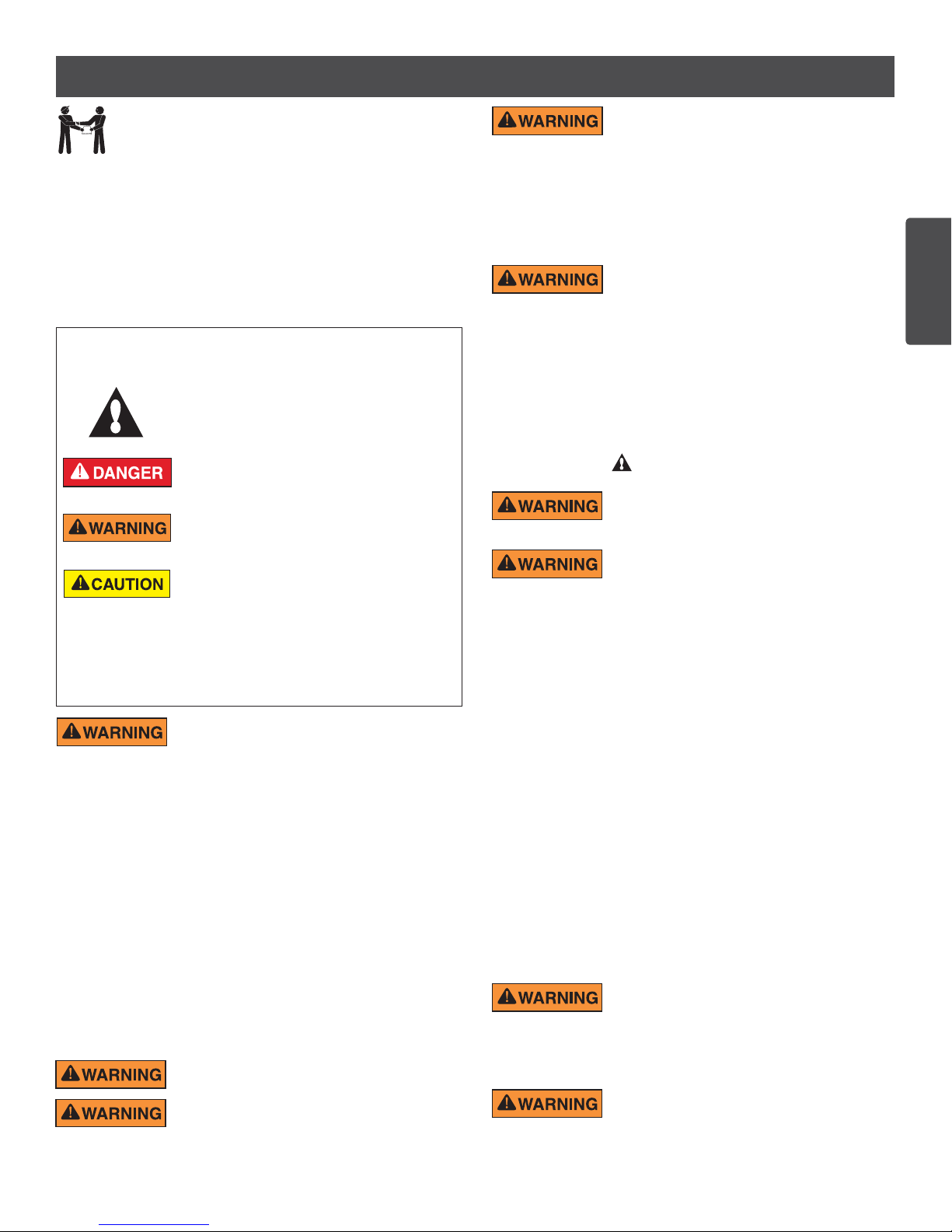
This is the safety alert symbol. When you see this
symbol on your system or in this manual, look for
one of the following signal words and be alert to
the potential for personal injury.
Warns about hazards that can cause death,
serious personal injury, or major property damage
if ignored.
Warns about hazards that may cause death,
serious personal injury, or major property damage
if ignored.
Warns about hazards that may or can cause minor
personal injury or property damage if ignored.
NOTE Indicates special instructions not related to
hazards.
Carefully read and follow all safety instructions in this manual and on
equipment. Keep safety labels in good condition; replace if missing or
damaged.
Before installing this product, read and follow all
warning notices and instructions which are included.
Failure to follow safety warnings and instructions can result in severe
injury, death, or property damage. Call (800) 831-7133 for additional free
copies of these instructions.
Codes and Standards
UltraTemp ETi heaters are listed by UL as complying with the latest edition
of the “UL Standard for Safety for Heating and Cooling Equipment”, UL
1995, CSA C22.2 No. 236 and ANSI Z21.56
Installation must be in accordance with all local codes and/or the latest
edition of the National Fuel Gas Code, ANSI Z223.1 and the latest
edition of the National Electrical Code, NFPA 70 (US).
Installation in Canada must be in accordance with the latest CAN/
CGA-B149.1 or .2 and CSA C22.1 Canadian Electric Code, part 1.
This heater, when installed, must be electrically grounded and bonded
in accordance with local codes, or, in absence of local codes, with the
National Electrical Code, ANSI/NFPA70 (US) or in Canada in accordance
with the Canadian Electric Code, part 1 as applicable.
Do not permit children to use this product.
Improper installation, adjustment, alteration, service
or m ai ntenance c an cause property damage,
personal injury or death. Installation and service must be performed
by a qualified installer, service agency or the gas supplier.
RISK OF ELECTRICAL SHOCK OR
ELECTROCUTION.
The electrical supply to this product must be installed by a licensed,
certified electrician or qualified personnel in accordance with the National
Electrical Code and all applicable local codes and ordinances. Improper
installation will create an electrical hazard which could result in death or
serious injury to pool or spa users, installers, or others due to electrical
shock, and may also cause damage to property. Read and follow the
specific instructions inside this guide.
For units intended for use in other than single-family
dwellings, a clearly labeled emergency switch
shall be provided as part of the installation. The switch shall be readily
accessible to the occupants and shall be installed at least 5 feet [1.52
m] away, adjacent to, and within sight of the unit.
Consumer Information and Safety
UltraTemp ETi heaters are designed and manufactured to provide safe
and reliable service when installed, operated and maintained according
to the information in this manual and the installation codes referred to
in later sections. Throughout the manual, safety warnings and cautions
are identified by the “ “ symbol. Be sure to read and comply with all of
the warnings and cautions.
The U.S. Consumer Product Safety Commission warns
that elevated water temperature can be hazardous.
See below for water temperature guidelines before setting temperature.
The following “Safety Rules for Hot Tubs”
recommended by the U.S. Consumer Product
Safety Commission should be observed when using the spa:
1. Spa or hot tub water temperatures should never exceed 104° F. [40°
C.]. A temperature of 100° F. [38° C.] is considered safe for a healthy
adult. Special caution is suggested for young children. Prolonged
immersion in hot water can induce hyperthermia.
2. Drinking of alcoholic beverages before or during spa or hot tub
use can cause drowsiness which could lead to unconsciousness
and subsequently result in drowning.
3. Pregnant women beware! Soaking in water above 100° F.
[38° C.] can cause fetal damage during the first three months of
pregnancy (which may result in the birth of a brain-damaged or
deformed child). Pregnant women should stick to the 100° F. [38°
C.] maximum rule.
4. Before entering the spa or hot tub, the user should check the
water temperature with an accurate thermometer. Spa or hot tub
thermostats may err in regulating water temperatures.
5. Persons with a medical history of heart disease, circulatory
problems, diabetes or blood pressure problems should obtain
their physician’s advice before using spas or hot tubs.
6. Persons taking medication which induce drowsiness, such as
tranquilizers, antihistamines or anticoagulants should not use
spas or hot tubs.
Should overheating occur or the gas supply fail
to shut off, turn off the manual gas control valve
to the heater. Do not use this heater if any part has been under water.
Immediately call a qualified service technician to inspect the heater and
to replace any part of control system and gas control which has been
underwater.
Risk of fire, carbon monoxide poisoning, or
asphyxiation if exhaust venting system leaks.
Only qualified service technicians should attempt to service the heater, as
leakage of exhaust products or flammable gas may result from incorrect
servicing.
ii
ENGLISH
ULTRATEMP ETI™ Hybrid Heater Installation and User’s Guide
iii
IMPORTANT WARNING AND SAFETY INSTRUCTIONS
The U.S. Consumer Product Safety Commission
warns that carbon monoxide is an “invisible killer”.
Carbon monoxide is a colorless and odorless gas.
1. Carbon monoxide is produced by burning fuel, including natural gas
and propane.
2. Proper installation, operation and maintenance of fuel-burning
appliances in the home is the most important factor in reducing
carbon monoxide poisoning.
3. Be sure that fuel burning appliances such as heaters are installed by
professionals according to manufacturer’s instructions and codes.
4. Always follow the manufacturer’s directions for safe operation.
5. Have the heating system inspected and serviced annually by a trained
service technician.
6. Install battery-operated carbon monoxide alarms. The alarms should
be certified to the requirements of the most recent UL, IAS, CSA and
IAPMO standard for carbon monoxide alarms. Test carbon monoxide
alarms regularly and replace dead batteries.
Hyperthermia occurs when the internal temperature of the body reaches a
level several degrees above normal body temperature of 98.6° F. [37° C.].
The symptoms of hyperthermia include: drowsiness, lethargy, dizziness,
fainting, and an increase in the internal temperature of the body.
The symptoms of hyperthermia include:
1. Unawareness of impending danger.
2. Failure to perceive heat.
3. Failure to recognize the need to leave the spa.
4. Physical inability to exit the spa.
5. Fetal damage in pregnant women.
6. Unconsciousness resulting in danger of drowning.
CARBON MONOXIDE GAS IS DEADLY!
THIS PRODUCT MUST BE INSTALLED AND
SERVICED BY A PROFESSIONAL SERVICE TECHNICIAN, QUALIFIED
IN POOL HEATER INSTALLATION. Some jurisdictions require that
installers be licensed. Check with your local building authority about
contractor licensing requirements. Improper installation and/or operation
could create carbon monoxide gas and flue gases which could cause
serious injury or death. Improper installation and/or operation will void
the warranty.
Exhaust from this pool heater contains toxic levels of carbon monoxide, a
dangerous, poisonous gas you cannot see or smell. Symptoms of carbon
monoxide exposure or poisoning include dizziness, headache, nausea,
weakness, sleepiness, muscular twitching, vomiting and inability to think
clearly. IF YOU EXPERIENCE ANY OF THE ABOVE SYMPTOMS,
IMMEDIATELY TURN OFF THE POOL HEATER, LEAVE THE VICINITY
OF THE POOL OR SPA AND GET INTO FRESH AIR IMMEDIATELY.
THE POOL HEATER MUST BE THOROUGHLY TESTED BY A GAS
PROFESSIONAL BEFORE RESUMING OPERATION.
EXCESSIVE CARBON MONOXIDE EXPOSURE CAN CAUSE BRAIN
DAMAGE OR DEATH.
• NEVER use this pool heater indoors.
• NEVER use this pool heater in the home or in partly enclosed areas
(such as garages). Install far from open windows, doors, vents and
other openings.
• Pentair strongly recommends that exhaust systems be initially and
periodically tested for proper operation. This testing can be accomplished
by using a hand-held carbon monoxide meter and/or by consulting with
a gas professional.
ULTRATEMP ETI™ Hybrid Heater Installation and User’s Guide
• Pool heaters must be used in conjunction with carbon monoxide detectors
installed near the pool heater. The carbon monoxide detectors must be
periodically inspected for proper operation so as to insure continued
safety. Broken or malfunctioning carbon monoxide detectors must be
replaced immediately.
This heater is equipped with an unconventional gas
control valve that is factory set at a pressure of -.2 inches
wc. Improper installation, adjustment, alteration, service or maintenance can
cause property damage, personal injury or loss of life. Installation or service
must be performed by a qualified installer, service agency or the gas supplier.
If this control is replaced, it must be replaced with an identical control. Do not
attempt to adjust the gas flow by adjusting the regulator setting.
Risk of fire or explosion from incorrect fuel use.
Do not try to run a heater set up for natural gas on
propane gas or vice versa. Only qualified service technicians should attempt
to convert heater from one fuel to the other. Do not attempt to alter the rated
input or type of gas by changing the orifice. If it is necessary to convert to a
different type of gas, consult your Pentair dealer. Serious malfunction of the
burner can occur which may result in loss of life. Any additions, changes,
or conversions required in order for the appliance to satisfactorily meet the
application needs must be made by a Pentair dealer or other qualified agency
using factory specified and approved parts. The heater is available for use
with natural gas only. It is not designed to operate with any other fuels. Refer
to the nameplate for the type of gas the heater is equipped to use. Use only
fuel for which the heater in designed.
Risk of fire or explosion from flammable vapors.
Do not store gasoline, cleaning fluids, varnishes,
paints, or other volatile flammable liquids near heater.
Risk of explosion if unit is installed near propane
gas storage. Propane (LP) gas is heavier than air.
Consult local codes and fire protection authorities about specific installation
requirements and restrictions. Locate the heater away from propane gas
storage and filling equipment as specified by the Standard for the Storage
and Handling of Liquefied Petroleum Gases, CAN/CSA B149.2 (latest edition)
or ANSI/NFPA 58 (latest edition).
Combustion air contaminated by corrosive chemical
fumes can damage the heater and will void the warranty.
Label all wires prior to disconnection when servicing
controls. Wiri ng errors can cause i mproper and
dangerous operation. Wiring errors can also destroy the control board.
• Connect heater to 240 Volt, 60 Hz., Single Phase power only.
• Verify proper operation after servicing.
• Do not allow children to play on or around heater or associated
equipment.
• Never allow children to use the pool or spa without adult supervision.
• Read and follow other safety information contained in this manual prior
to operating this pool heater.
General Specifications
Installation Location Certified for Use: OUTDOOR USE ONLY. Failure
to provide the proper clearances outlined on page 3-4 will lower the
performance of the heat pump and void the warranty.
Water Pipe/Heater Connection: Plastic 2” PVC (Unions included)
Flow Rate:
Maximum 120 gpm [456 lpm] - If system flow rate exceeds 120 gpm, a
bypass valve is required.
Minimum 30 gpm [110 lpm].
Maximum Working Water Pressure 50 psi
For Electrical Supply and Voltage Requirements, refer to the table on
page 35.

GENERAL INFORMATION
1
Heater Introduction
Thank you for choosing the UltraTemp ETi™ Hybrid
Heater. Proper installation and service of your new heating
system, and correct chemical maintenance of the water
will ensure years of heater operation. The UltraTemp
ETi heater is equipped with Pentair’s advanced heater
technology which includes a heat pump and a pool heater,
with a multifunction temperature controller to continuously
monitor the hybrid heater for proper operation. These
heaters are designed with direct spark ignition (DSI) for
on demand heat, which eliminates the need for a standing
pilot.
The heater is certified as complying with the Standard
for Gas Fired Pool Heaters, ANSI Z21.56/CSA 4.7, and
with the Standard for Heating and Cooling Equipment, UL
1995/CSA C22.2 No. 236-15. This heater is intended for
use in heating fresh water swimming pools or spas.
Installation Requirements
Correct installation is required to assure safe operation.
The requirements for Pentair heaters include the following:
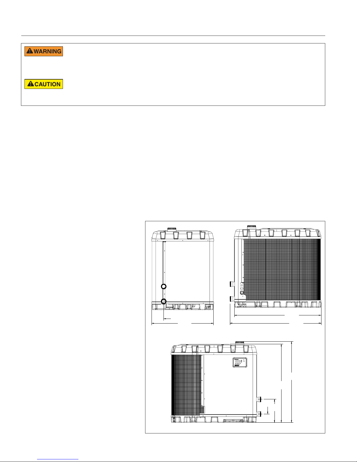
• Dimensions for critical connections (see Figure 1,
page 2).
• Field assembly (if required).
• Appropriate site location and clearances (pages 2-4).
• Proper electrical wiring (pages 14-16).
• Adequate water flow (see
page iii).
This manual provides the information needed to meet
these requirements. Review all application and installation
procedures completely before continuing the installation.
General Specifications,
General Installation Information
1. Installation and service must be performed by
a qualified installer or service agency, and must
conform to all national, state, and local codes.
2. Heaters get electrical power from an external
source and provide a dual electronic thermostat
control system for pool/spa combinations or preheat
convenience.
3. The heater is designed for the heating of chlorine,
bromine or salt system swimming pools and spas.
It should NOT be used as a space heating boiler, or
general purpose water heater.
4. The heater should be located in an area where
leakage of the heater or connections will not result in
damage to the area adjacent to the heater or to the
structure. When such locations cannot be avoided, it
is recommended that a suitable drain pan, adequately
drained, be installed under the heater. The pan must
not restrict air flow.
5. The heater is designed for outdoor operation
in non-freezing conditions only. If installed for
seasonal use in freezing climates, the heater
must be winterized to avoid freeze damage. See
Winterizing, page 34.
General Features
• Dual digital thermostats offer precise temperature
control to maintain the desired separate water
temperatures in pool/spa combinations without
overheating or wasting energy.
• Long-life corrosion resistant composite plastic
cabinet stands up to severe climates and pool
chemicals.
• 100% pure titanium heat pump and direct-fire
gas heat exchangers assure corrosion-free
performance for extra long life.
• Self-diagnostic control panel monitors and
troubleshoots heater operations to ensure safe,
dependable operation.
• Automatic Defrost feature senses refrigerant
temperature and prevents the heat pump
evaporator coil from freezing, allowing the heater to
operate at even lower temperatures.
• Compatible with all automated control packages.
RS-485 communication compatible with
EasyTouch® Control Systems.
• Thermostatic expansion valve (TXV) controls
refrigerant flow for optimum efficiency and BTU
output over a wider operating range.
• Elevated base pan for positive drainage of
condensation.
• 2-inch plumbing connections for easy installation.
• Separate isolated electrical compartment prevents
internal corrosion, extends heater life.
• Adjustable timer allows the operator to set the
heater to run for a predetermined time. Incremental
by 10 minutes to a maximum of 99 hours.
• An extensive list of operational conditions, alarms
and water temperatures are logged on the control
board. This information is available for the user to
track performance and troubleshoot issues.
• Four unique operating modes: Heat Pump only,
Gas Heater only, Dual and Hybrid.
ENGLISH
ULTRATEMP ETI™ Hybrid Heater Installation and User’s Guide
2
POSITIONING THE HEATER
CARBON MONOXIDE GAS IS DEADLY – Exhaust from this pool heater contains carbon monoxide, a dangerous, poisonous gas you
cannot see or smell. Symptoms of carbon monoxide exposure or poisoning include dizziness, headache, nausea, weakness, sleepiness,
muscular twitching, vomiting and inability to think clearly. IF YOU EXPERIENCE ANY OF THE ABOVE SYMPTOMS, IMMEDIATELY TURN OFF THE POOL
HEATER, LEAVE THE VICINITY OF THE POOL OR SPA AND GET INTO FRESH AIR IMMEDIATELY. THE POOL HEATER MUST BE THOROUGHLY TESTED
BY A GAS PROFESSIONAL BEFORE RESUMING OPERATION. EXCESSIVE CARBON MONOXIDE EXPOSURE CAN CAUSE BRAIN DAMAGE OR DEATH.
When pool equipment is located below the pool surface, a leak from any component can cause large scale water loss or flooding.
Pentair Water Pool and Spa, Inc. can not be responsible for such water loss or flooding which may cause damage to property or to the
product. Avoid placing the heater in locations where it can cause damage by water or condensate leakage. If this is not possible, provide a suitable drain pan
to catch and divert any leakage.
Only a qualified service person should install the
UltraTemp ETi™ Hybrid Heater. Before installing this
product, refer to the Important Warning and Safety
Instructions on page ii.
In the United States, installation must be in accordance
with local codes and the most recent edition of the
National Fuel Gas Code, ANSI Z223.1/NFPA-54. In
Canada, install the heater in accordance with local codes
and the most recent edition of the Natural Gas and
Propane Installation Code, CAN/CSA B149.1.
Materials Needed for Installation
The following items are needed and are to be supplied by
the installer for all heater installations:
1. Plumbing connections (2-inch).
2. Level surface for proper drainage.
3. Suitable electrical supply line. See rating
plate on unit for electrical specifications.
A junction box is not needed at the
heater; connections are made inside
of the heater electrical compartment.
Conduit may be attached directly to the
heater jacket.
4. Electric cutout switch that will interrupt
all power to the unit. This switch must be
within line of sight of the heater. Check
local codes for requirements.
5. Watertight conduit to run the electrical
supply line.
6. Suitable gas supply line with sediment
trap (see Table 1 on page 11 for sizing
requirements).
6.7”
(170mm)
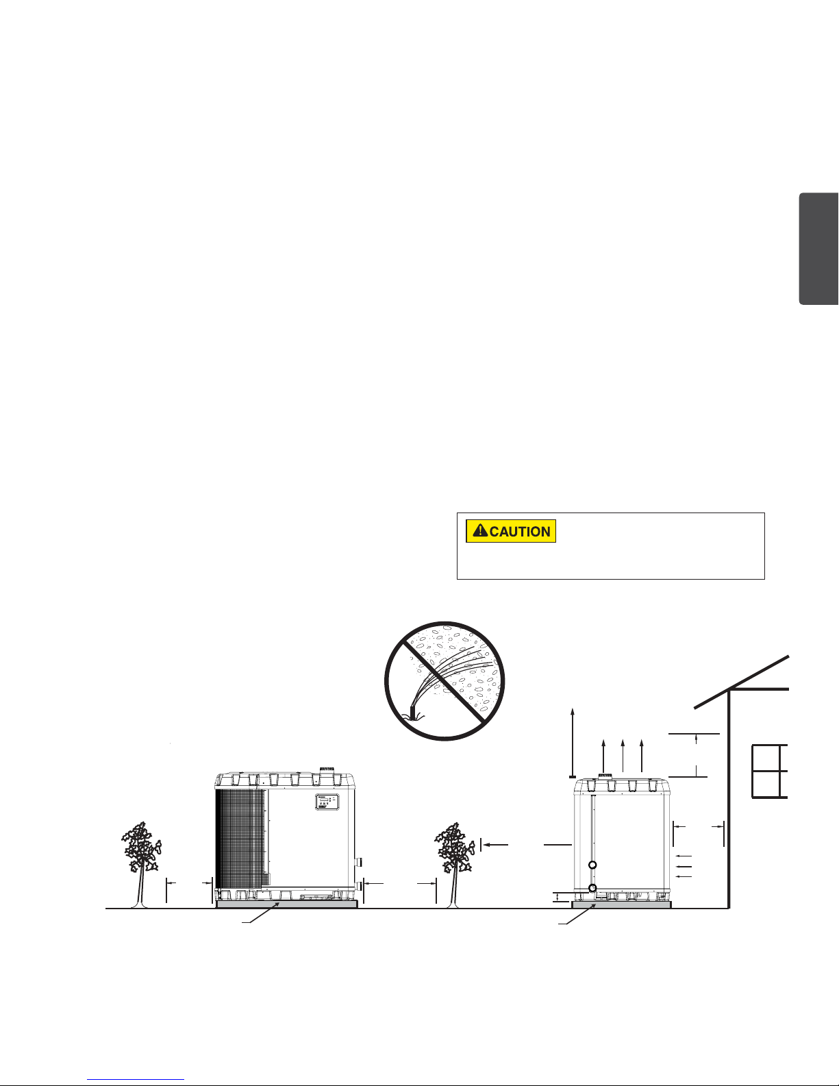
Lawn Sprinklers
Avoid placing lawn sprinkler near the heater they can spray water into the heater and void the
warranty. Be sure to direct any spraying water away
from the heater. Note the wind direction to be sure
water from sprinklers is not blown toward the heater.
Sprinkler heads can produce high water pressure and
spray at an angle, different from typical rain and humid
weather. Also, sprinklers connected to a well water
system can cause mineral build up on the evaporator
coils and electronics. Salt water can also be an issue if
located near the coast.
48.3”
34.4”
(874mm)
(1227mm)
50.7”
(1288mm)
Roof Run-off
Make sure the heater is not located where
large amounts of water may run-off from a
roof into the unit.
Sharp sloping roofs without gutters will
allow massive amounts of rain water, mixed
with debris from the roof to be forced
through the unit. A gutter or down spout
may be needed to protect the heater.
ULTRATEMP ETI™ Hybrid Heater Installation and User’s Guide
4.7”
(119mm)
(1115mm)
12.9”
(328mm)
43.9”
45.7”
(1146mm)
Figure 1
Equipment Pad
For proper drainage of condensation and rain water, place the heater on a flat slightly pitched surface, such as a
concrete or fabricated slab (pad).
If possible, place the pad at the same level or slightly higher than the filter system equipment pad.
The equipment pad should also be in an area where leaves or other combustible debris will not collect on or
around the heater.
Note:
Be sure that the pad is pitched not more than 1/4 in. per foot in any direction as needed for runoff.
Note: The equipment pad should be no less than 4 in. (100 mm) thick.
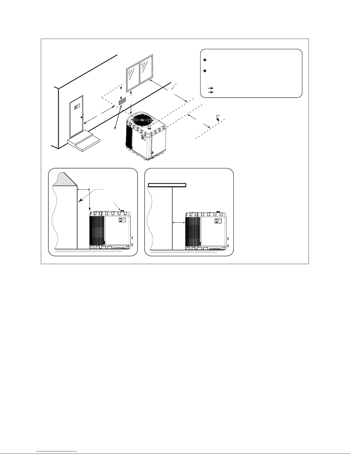
Recommended Clearances
All criteria given in the following sections reflect
minimum clearances. However, each installation must
also be evaluated, taking into account the prevailing
local conditions such as proximity and height of walls,
and proximity to public access areas.
The UltraTemp ETi™ Hybrid Heater must be placed
to provide clearances on all sides for maintenance
and inspection. Refer to Figure 2 for a visual
representation of the proper clearances.
1. At least 30 inches [610 mm] of clearance is
required on both the plumbing and control panel
side of the heater. This will provide necessary
room for servicing.
2. At least 12 inches [305 mm] of clearance must
be available on all the other sides of the heater to
allow for proper air flow.
3. If the heater is to be installed under a cover or
under a vertical overhang, the unit must have a
minimum of five (5) feet [1.5 m] clearance from
the top of the heater.
4. Install a minimum of five (5) feet [1.52 m] from the
inside wall of the pool or spa unless the heater is
separated from the pool or spa by a five (5) foot
[1.52 m] high solid fence or other permanent barrier.
Canadian installations require a minimum of three
(3) meters [9.84 ft] from pool water.
5. Install heater a minimum of 12 in. [305 mm] from the
wall of the house.
6. For minimum exhaust vent clearances, see Figure 3
on next page.
Note: In Canada, the heater must be installed with
the top of the vent at least 10 ft. (3 m) below, or to
either side of, any opening into a building.
If installing the heater next to or near an air
conditioning unit, heater or another gas pool
heater, allow a minimum of 36 in. (91.4 cm) between the unit and
the heater.
3
ENGLISH
12"
min.
(305 mm)
SLAB
NO SPRINKLERS
SERVICE
ACCESS
30"
min.
(762 mm)
Figure 2: Heater Clearances
ULTRATEMP ETI™ Hybrid Heater Installation and User’s Guide
SERVICE
ACCESS
30" min.
(762 mm)
3"
(76 mm)
SLAB
OPEN
AIR FLOW OUT
OVER HANG
5
FT min.
(1.5 m)
12
"
min.
(305 mm)
AIR
FLOW
IN
4
Recommended Clearances (cont.)
OUTDOOR INSTALLATION
VENTING GUIDELINES
3’
(0.9m)
4’
(1.2m)
4’
(1.2m)
From window
or door
Vent Termination:
Must be at least 3 ft. (0.9 m) above any forced
air inlet located within a 10 ft. (3.5 m) radius.
Must be located 12 in. (30.5 cm) away from the building
wall and the following distances away from any building
wall openings, included but not limited to vented eaves,
doors, windows, gravity air inlet:
4 ft. (1.2 m) below,
4 ft. (1.2 m) horizontally
Building
12"
(30.5cm)
4’
(1.2m)
Force
Air Inlet
SIDE VIEW
From building wall
Exhaust Grill
(Vent)
Roof Overhang
Building
4’
(1.2m)
Check local b
for setback requirements.
ROOF OVERHANG
12"
(30.5cm)
Property Line
uilding codes
Figure 3:
Vent Clearances
ULTRATEMP ETI™ Hybrid Heater Installation and User’s Guide
5
Flue Gas Condensation
Management
The UltraTemp ETi™ Hybrid Heater is a condensing
appliance. The flue gases will produce condensate
while in operation and must be drained correctly.
The condensate pH level is between 3.1 and 4.2.
Pentair recommends neutralizing the condensate
to avoid potential damage over time to the drainage
system, and to comply with local water authorities
where applicable. To neutralize the condensate, use
the Condensate Neutralizer Cartridge provided with
the heater. The condensate drain must be installed
so as to prevent accumulation of condensate. When
a condensate pump is not used, the tubing must
continuously slope downward toward the drain with no
spiraling.
Note: Consult local codes for treated condensate
disposal method.
DO NOT allow the exhaust flue gases to vent
through the neutra lizer. All condensate drains
MUST have a trap to prevent flue gas leakage. Flue gas leakage can
cause personal injury or death from carbon monoxide. Check with local
authorities for regulations regarding discharge of condensate to the drain
sewer system.
pH levels of 5.0 and below may harm some floor
drains and/or pipes, particularly those that are metal.
Ensure that the drain, drainpipe, and anything that will come in contact
with the condensate can withstand the acidity. Damage caused by failure
to install a neutralizer kit or to adequately treat condensate will not be the
manufacturer’s responsibility.
Preventative Maintenance
Annual condensate assembly inspection: Inspect
the internal tubing top for any dirt or particles that
could collect and clog the condensate neutralizer
cartridge.
Based on operating conditions, algae buildup in the
condensate cartridge may occur. Excessive algae
buildup can prevent proper condensate drainage
ENGLISH
DO NOT expose the condensate cartridge to
freezing temperatures without draining. This
could damage the cartridge. See page 34 for proper Winterizing
instructions.
Condensate Cartridge Service
If the control board reads “REPLACE CNC”, check
pH of condensate liquid. If the pH is below 5.0,
replace the condensate cartridge with a Condensate
Neutralizer Kit, (P/N 475954).
If the pH is not known, replace the condensate
cartridge when the control board recommends.
To clear this alarm, press the DOWN arrow and MODE
button simultaneously. The alarm may take a few
moments to clear after the buttons are pressed.
Figure 4: Condensate Neutralizer Cartridge Installed
Mounting
Bracket
in the Heater Base
Internal
Tubing
Condensate Neutralizer
ULTRATEMP ETI™ Hybrid Heater Installation and User’s Guide
6
ANCHOR
CLAMPS
ANCHOR
CLAMPS
ANCHOR
CLAMPS
FILTER
HEATER
TO
POOL
GATE
VALVE
FROM
POOL
FROM
FILTER
MANUAL
BY-PASS
1/4” x 2-1/4” Stainless
Steel Anchor Bolt
(not included)
INSTALLATION
The installation instructions contained in this manual are designed for use by qualified personnel only, trained especially
for installation of this type of heating equipment and related components. Some states require installation and repair by
licensed personnel. If this applies in your state, be sure your contractor possesses the appropriate license.
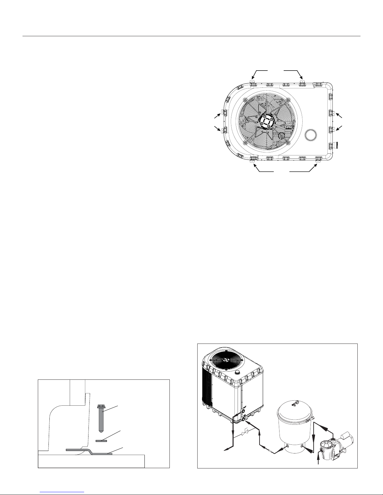
Anchor Clamp Installation
Installation of the anchor clamps is recommended in all
installations. Installation of the anchor clamps is required
in Florida (see Florida Building Code 301.13).
Anchor clamps hold the heater to the equipment pad in
order to withstand high winds caused during extreme
weather (i.e. hurricanes).
Note: Anchor clamps are included with the heater. They
can be found attached to the wood pallet that the heater
is shipped with.
To install the anchor clamps:
1. Be sure the heater is in its permanent location on the
equipment pad.
2. Place the clamps at the base of the heater in the eight
(8) locations, shown in Figure 5.
Note: Bolts and washers are not included with
the heater. The installer must provide 1/4” x 2-1/4”
stainless steel anchor bolts and the appropriate
size washers to mount the clamp to the concrete
equipment pad. Be sure to check local codes.
3. Fit the hook of each clamp into the slots in the base
panel of the heater.
4. Mark the position of the hole in each clamp on the
equipment pad.
5. Use a masonry drill bit and drill a hole in the cement
with a diameter as determined by the concrete anchor,
at each of the marks on the concrete equipment pad.
The hole should be approximately 2-3/4” (7 cm.) deep.
6. Position the anchor clamps so that the holes in the
clamps are over the drilled holes in the equipment pad
and the other end of the clamp is secured inside of the
heater base.
7. Insert an anchor bolt through each clamp into the anchor
and tighten to secure the clamp and heater to the
equipment pad. See Figure 6.
Note: Anchor bolts should be tightened to around
four (4) ft/lbs.
CLAMPS
ANCHOR
Figure 5: Anchor Clamp Locations
System Layout
The image below shows the standard plumbing layout with
a single UltraTemp ETi™ Hybrid Heater unit. Follow Figure
7 from right to left for the standard plumbing sequence.
Arrangement of pool system components (other than the
standard plumbing image below), and the location of the
heater (above or below the pool water surface) can affect
the operation of the heater’s water pressure switch.
The pressure switch can be adjusted to accommodate this
effect if the heater water connections are no more than six
(6) feet [1.82 m] below the pool water surface.
See instructions for pressure switch adjustment on pages
10-11. If the heater is installed outside of this range, an
external water flow switch may need to be installed in the
plumbing upstream of the heater.
Note:
Be advised that when pool equipment is located
below the pool surface a leak can result in large-scale
water loss or flooding. Pentair is not responsible for such
water loss or flooding or damage.
Figure 7
Heater
ULTRATEMP ETI™ Hybrid Heater Installation and User’s Guide
Base
Concrete Pad
1/4” Stainless
Steel Washer
(not included)
Anchor Clamp
Figure 6
PUMP
Internal Automatic Flow
Control Valves
The inlet/outlet header of the UltraTemp ETi™ Hybrid
Heater comes equipped with an internal water
management system with two automatic flow control
valves. The automatic flow control valves maintain the
proper flow through the heater at rates up to 120 gpm
(454 lpm). If the filter system flow rate is higher than
120 gpm (454 lpm), install a manual bypass valve.
Note:
Be advised that if your circulation pump is over 2
HP or if the total flow exceeds 120 gpm (454 lpm), you
will have to add an external bypass valve. Excess water
flow will damage the heat exchanger.
Water Connections and Plumbing
Always be sure that flow requirements and pool
water turnover rates can be maintained with the
installation of additional equipment and plumbing restrictions.
2 in. Quick Connect fittings have been installed on the
water inlet and outlet connections. Filtered cool water
is plumbed to the heater.
Plastic piping (PVC Schedule 40) should be
connected to the heater. The unions, provided with the
unit, accept 2 in. PVC pipe.
The heater requires proper water flow and pressure for
its operation. To properly operate the heater requires a
flow rate of at least 30 GPM, but optimal performance
is achieved at 50 GPM. The maximum working
pressure for the system is 50 PSI.
See Figure 8 for the recommended installation. The
filter pump discharges to the filter, the filter discharges
to the heater, and the heater discharges directly to the
pool or spa.
A manual bypass valve should be installed before the
heater when the pump flow exceeds 120 GPM (454
LPM).
Make sure that the outlet plumbing from the heater
contains no shut-off valves or other flow restrictions
that could prevent flow through the heater (except for
pool installations as noted below, or winterizing valves
where needed). To switch flow between the pool and
spa, use a diverter valve. Do not use any valve that
can shut off the flow.
Install the chemical feeder downstream of the heater.
Install a chemical resistant one-way check valve
between the heater and the chemical feeder to prevent
back-siphoning through the heater when the pump is
off.
Note: If the heater is plumbed in backwards, it will
cycle continuously. Make sure piping from filter is not
reversed when installing heater.
Connect the heater directly to 2 in. PVC pipe, using
the provided unions. Heat sinks are not required.
The low thermal mass of the heater will prevent
overheating of the piping connected to the pump even
if the heater shuts down unexpectedly.
7
Occasionally a two-speed pump will not develop enough
pressure on the low speed to operate the heater. In this case,
run the pump at high speed only to operate the heater. If
this does not solve the problem, do not try to run the heater.
Instead, correct the installation.
Do not operate the heater while an automatic pool cleaner is
also operating. If the circulation pump suction is plugged (for
example by leaves), there may not be adequate flow to the
heater. Do not rely on the pressure switch in this case.
Main
Drain
Pool
From Pool
3-Way
Valve
Spa
3-Way
Valve
Chlorinator
Check Valve
Filter
Pump
3-Way
Valve
Figure 8
Heat Pump Drainage Connection
Condensation (water) will be produced while the heat pump
is in operation. The heater base is designed to allow the
condensation to exit through the bottom drain port when the
unit is running.
Before operating the heater for the first time, the drain hose barb
must be installed into the threaded drain port located in the base
of the heater.
To install the Drain Hose Barb and Drain Hose:
1. Thread the drain hose barb into the threaded drainage port in
the base of the heater. See Figure 9.
2. Connect a 5/8” garden hose to the hose barb.
3.
Ensure the end of the garden hose is positioned so that drainage
will flow away from the heater and equipment pad.
Figure 9
DRAIN HOSE BARB
5/8" X 1/2" NPT
HEAT PUMP
DRAINAGE PORT
ENGLISH
ULTRATEMP ETI™ Hybrid Heater Installation and User’s Guide
8
Isolation and Check Valves
When any equipment is located below the surface
of the pool or spa, valves should be placed in the
circulation piping system to isolate the equipment from
the pool or spa. Check valves are recommended to
prevent back-siphoning. Back-siphoning is most likely
to occur when the pump stops, creating a pressuresuction differential. Do NOT sanitize the pool by
putting chlorine tablets or sticks into the skimmer(s).
When the pump is off, this will cause a high
concentration of chlorine to enter the heater, which
could cause corrosion damage to the heat exchanger.
Exercise care when installing chemical feeders
so as to not allow back siphoning of chemical into
the heater, filters or pump. When chemical feeders are installed in the
circulation of the piping system, make sure the feeder outlet line is down
stream of the heater, and is equipped with a positive seal noncorrosive
Check Valve, (P/N R172288), between the feeder and heater.
Manual By-Pass Valve
Where the water flow rate exceeds the maximum
120 GPM, a manual bypass should be installed. After
installing the valve, adjust the valve to bring the flow
rate within the acceptable range. Then remove the
valve handle or lock it in place to avoid tampering.
Lower Gas Engine
Manifold Plug
Figure 10
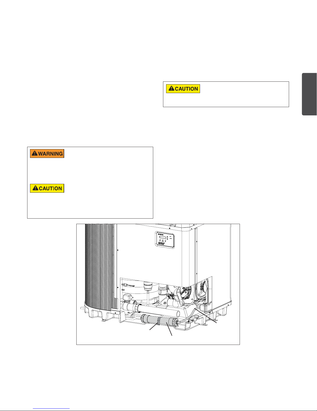
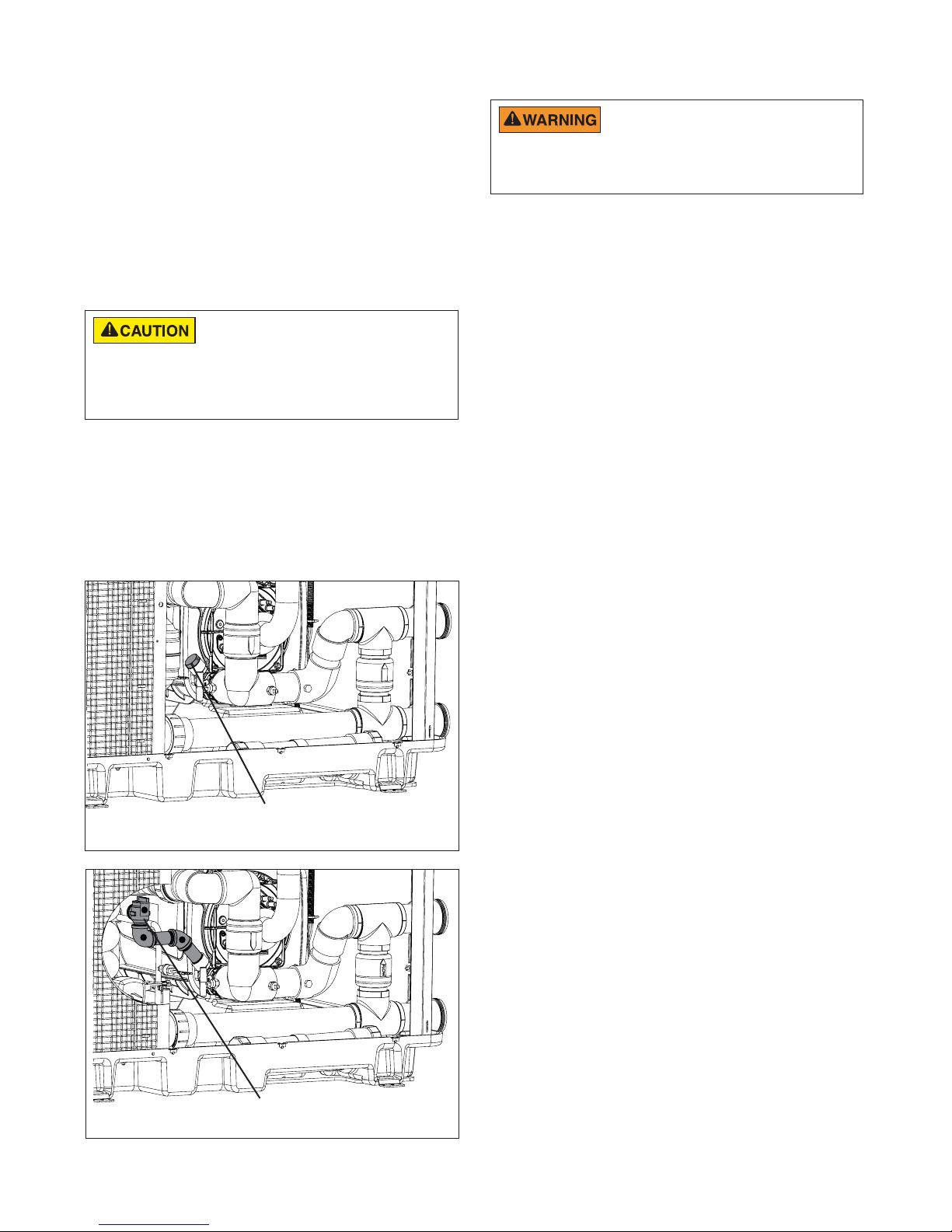
Pressure Relief Valve (PRV)
Ex p los i o n ha zar d ! A n y he ate r ins t all e d
with restri ctive devices in th e piping system
downstream from the heater, (including check valves, isolation valves,
flow nozzles, or therapeutic pool valving), must have a relief valve
installed as described in this section.
Canadian code, and some U.S. local codes, may
require installation of a Pressure Relief Valve (PRV).
Purchase and install a Hybrid Pressure Relief Valve
Kit (P/N 475943) complying with the ANSI/ASME
Boiler and Pressure Vessel Code, having a capacity
equal to the Btu/hr rating of the heater.
Note: The relief pressure of the valve MUST NOT
EXCEED 50 PSI. The relief valve must be installed
vertically.
To install the pressure relief valve:
Note: Be sure to use threaded seal tape (PTFE) or
equivalent, on all threaded metal pipe connections.
1. Remove the heater service panel.
2. Remove the lower gas engine manifold 3/4” brass
plug. See Figure 10.
3. Thread the Schedule 40 brass pipe and 45-degree
elbow [1], included in the PRV kit, into the lower
gas engine manifold. The elbow should be oriented
so that the elbow’s female thread is horizontal. See
Figure 11.
4. Thread the second Schedule 40 brass pipe and
90-degree elbow [2] into the 45-degree elbow [1].
Ensure that the open end of the 90-degree elbow is
oriented vertically. See Figure 11.
5. Install the Pentair pressure relief valve (P/N
072138), included in the PRV kit, or an equivalent
50 PSI 3/4” ASME-Type IV relief valve [3] into the
90-degree elbow [1]. See Figure 11.
Note: Ensure the relief valve is oriented so the
outlet is facing straight into the heater and will not
direct towards the service panel.
6. Inspect the valve annually to ensure proper
operation. Replace if improper operation is
determined.
!
"
Pressure Relief
Valve (Installed)
ULTRATEMP ETI™ Hybrid Heater Installation and User’s Guide
Figure 11
Extend 12" (305 mm)
past end heater
inlet for hydraulic
balancing
Extend 12" (305 mm)
past end heater
inlet for hydraulic
balancing
From Pool Pump
Flow Meter
Minimum
2" PVC Pipe
2" PVC Pipe
Flow Meter
To Pool
OPTIONAL
2" Check Valve Bypass
Check Valves are
optional on heater inlets
but will help system
balancing
36"
(914 mm)
12"
Extend 12"
(305 mm) past
end heater
inlet for hydraulic
balancing
Extend 12" (305 mm)
past end heater
inlet for hydraulic
balancing
From Pool Pump
Flow Meter
Minimum
3" PVC Pipe
2" PVC Pipe
Flow Meter
To Pool
3" Ball Valve Bypass
Check Valves are
optional on heater inlets
but will help for system
balancing
36"
(914 mm)
2" PVC Pipe2" PVC Pipe
2" PVC Pipe
3" PVC Pipe3" PVC Pipe
120 GPM (456 lpm)
Minimum
(305 mm)
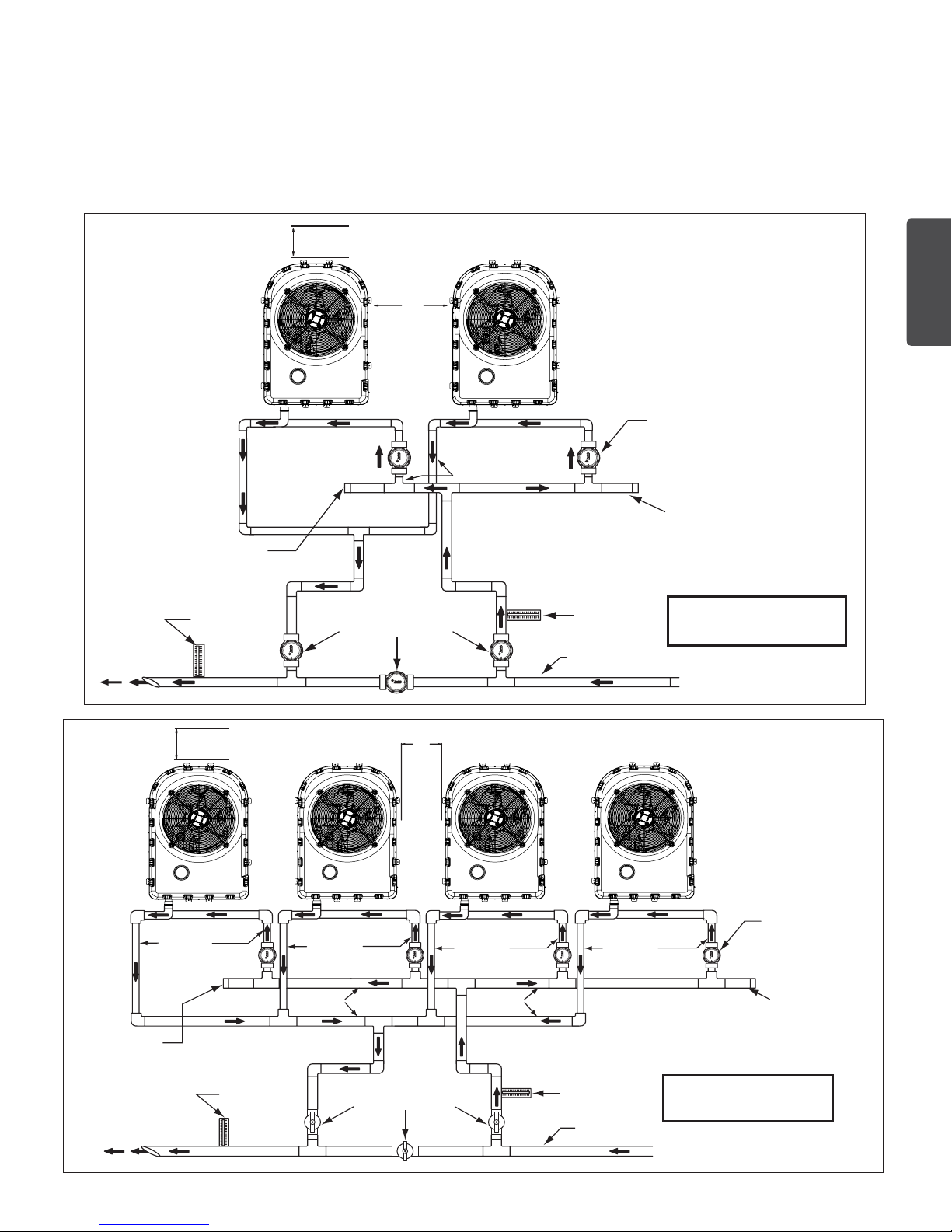
Multi-Heater Installations
All plumbing on multiple heater installations must be done in parallel (see Figure 12 and 13 below). An equal flow of
water to each heater is important for optimum operation.
Note: It may be necessary to adjust the water pressure switch if a unit is installed below the water level. Refer to page
10-11 for details on when and how to adjust the pressure switch.
Each heater in a multiple unit installation allows a maximum flow rate of 100 gpm (380 lpm) and requires a minimum
of 30 gpm (110 lpm).
9
(305 mm)
Figure 12
Dual Heater Layout
60 GPM (220 lpm)
Minimum
ENGLISH
12"
Figure 13
Multiple Heater
Layout
ULTRATEMP ETI™ Hybrid Heater Installation and User’s Guide
10
FILTE
S
SPA
OOL
A
RETURN
OOL
N
CHECK
VALVE
FROM SOLAR
TO SOLAR
PUMP
POOL
DRAIN
SPA
DRAIN
CHECK
VALVE
SPA
MAKE-UP
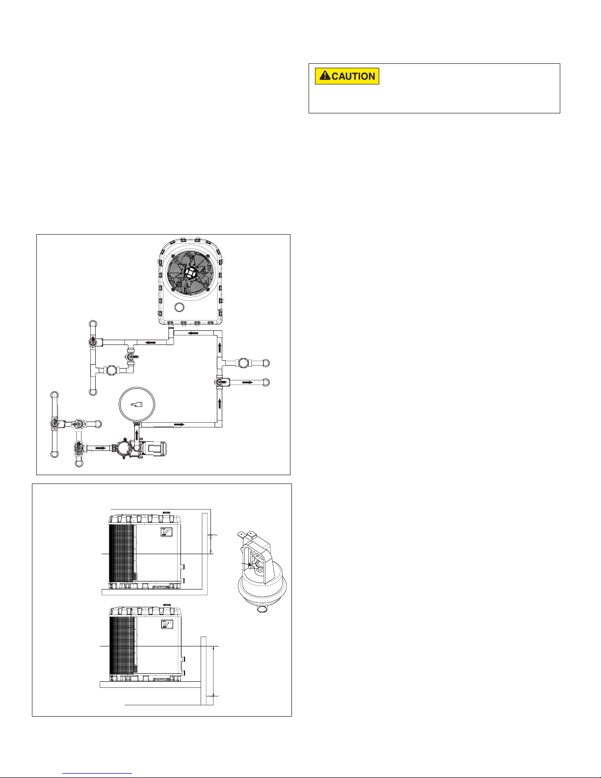
Solar Installations
The UltraTemp ETi™ Hybrid Heater can be used in
combination with other heating schemes such as solar. All
heat sources must be plumbed in series to work correctly
and efficiently.
A recommended plumbing layout for a heater-solar
combination heating system for a pool / spa combination
is shown below (Figure 14). Your system may not contain
all of these components, but the basic plumbing will apply
by eliminating the component in the illustration that is not a
part of your system.
Note: Water temperatures produced by supplemental
heating sources, such as solar, are not regulated or
controlled by the heater and may exceed the maximum
temperature allowed.
P
RETUR
P
SP
Figure 14
Heater-Solar Layout
Turn star wheel clockwise to raise
pressure set point
Turn star wheel counterclockwise to
lower pressure set point
A reference scale is on
the back of pressure switch
Water Pressure
Figure 15
Switch
Star Wheel
Water Pressure Switch Adjustment
The water pressure switch should be adjusted to turn
the heater off when the pump is off. Setting the switch
to close at too low of a flow can damage the appliance. Adjust the switch to
turn the heater off, not on.
The pressure switch is preset at the factory for activation
at 6 psi [41.4 kPa]. This factory setting works for most
basic installations. Only adjust the water pressure switch
if the heater does not operate when the proper flow is
applied to unit or if the heater does not shut off when
the filter pump is off. Occasionally, unusual plumbing
configurations or necessary restrictions in the plumbing
may cause pressure sensing problems. In these rare
situations, the plumbing system configuration may require
adjustment of the water pressure switch.
Adjustment of the pressure switch may be necessary if any
part of the filter system piping is 3 feet [0.91 m] or more
above the top of the heater.
In general, if the heater is installed more than 6 feet [1.83 m]
below the pool surface, an external water flow switch must
be added to the plumbing system.
On some installations, the piping from the heater to the pool
is very short. The back pressure could be too low to trigger
the pressure switch. If this happens, install a directional
fitting or elbow where the return line enters the pool. This
will increase back pressure for the heater to operate properly.
Be sure to check that the system flow is above the minimum
requirement of 30 gpm (110 lpm) after the directional fitting
installation.
Be sure the pool filter is clean before making any pressure
switch adjustment: A dirty filter will restrict the water flow and
the pressure switch cannot be adjusted properly.
To adjust the pressure switch:
The following adjustment is for installations where the
heater is
1. Be sure that all valves in the system are set to allow
2. Set the heater temperature above the actual temperature
3. Once the heater is running, turn off the filter pump. The
4. If the heater continues to operate when the filter pump is
5. Remove the heater’s left front panel and remove
6. Slowly rotate the adjustment wheel on the water pressure
below pool water level.
water flow through the heater. Start the filter pump.
to call for heat. Turn the heater ON.
heater should turn off immediately.
off, then the water pressure switch needs to be adjusted.
remaining right front panel. The water pressure switch
is located in the water plumbing in the lower corner of
the heater.
switch in a counterclockwise direction until the “LOW
WATER FLOW” Alarm shows on the LCD, the red
SERVICE light turns ON, and the heater stops. See
Figure 15.
ULTRATEMP ETI™ Hybrid Heater Installation and User’s Guide
Water Pressure Switch Adjustment (cont.)
7. Check the setting of the water pressure switch by
starting and stopping the filter pump and checking
the control panel and operation of the heater between
each flow change.
8. If the water pressure switch cannot be adjusted to
accommodate the conditions listed above, an external
flow switch must be added to the plumbing system
to ensure that the heater will not operate without the
proper flow through the heat exchanger.
The following adjustment is for installations where the
heater is above pool water level.
1. Be sure that all valves in the system are set to allow
water flow through the heater. Start the filter pump.
2. Set the heater temperature above the actual
temperature to call for heat. Turn the heater ON.
3. If the LCD shows a “LOW WATER FLOW” Alarm and
red SERVICE light is present then the water pressure
switch needs to be adjusted.
4. Remove the UltraTemp ETi™ Hybrid Heater’s left front
panel and remove remaining right front panel. The
water pressure switch is located in the water plumbing
in the lower corner of the heater.
5. Slowly rotate the adjustment wheel on the water
pressure switch in a counterclockwise direction until
the “LOW WATER FLOW” Alarm and red SERVICE
light vanish, time delay countdown will start.
6. Once the heater is running, turn off the filter pump. The
heater should turn off immediately.
7. If the heater continues to operate when the filter pump
is off, turn the adjustment wheel on the water pressure
switch in a clockwise direction until the “LOW WATER
FLOW” Alarm shows on the LCD, the red SERVICE
light turns ON, and the heater stops.
8. Check the setting of the water pressure switch by
starting and stopping the filter pump and checking
the control panel and operation of the heater between
each flow change.
9. If the water pressure switch cannot be adjusted to
accommodate the conditions listed above, an external
flow switch must be added to the plumbing system
to ensure that the heater will not operate without the
proper flow through the heat exchanger.
11
Gas Connections
The use of Flexible Gas Connectors (FLEX) is NOT
recommended unless they are properly sized according
to the supplier recommendations for the heater rating. In all cases, the
connectors must be bonded to the electrical service grounding point or, when
provided, the lighting protection grounding point according to the latest edition
of the National Fuel Gas Code.
Gas Line Installation
When sizing gas lines, calculate three (3) additional feet of
straight pipe for every elbow used. When installing the gas
line, avoid getting dirt, grease or other foreign material in
the pipe as this may cause damage to the gas valve, which
may result in heater failure.
The gas meter should be checked to make sure that it will
supply enough gas to the heater and any other appliances
that may be used on the same meter. The gas line from
the meter will usually be of a larger size than the gas
valve supplied with the heater. Therefore a reduction of the
connecting gas pipe will be necessary. Make this reduction
as close to the heater as possible.
The heater requires a gas supply of no less than 4 in.
(10.2 cm) wc, and no more than 10.5 in. (27 cm) wc for
natural gas (no more than 14 in. [36cm] for propane gas).
Gas supply pressures outside of this range may result in
improper burner operation. A minimum flowing or dynamic
inlet pressure (while the heater is running) of 4 in (10.2 cm)
wc is required to maintain input rating with no more than a
2 in. pressure drop between static and dynamic. The gas
supply must be installed in accordance with the National
Fuel Gas Code, ANSI Z223.1, or standard CSA B149.1,
Natural Gas and Propane Installation Codes, as applicable
and all applicable local codes. Install a manual shut-off
valve and a sediment trap and union located outside the
heater panels, see Figure 17 on the next page. Do not
use a restrictive gas cock. The following minimum gas pipe
sizes are recommended for natural gas supply piping, see
Table 1 below. Check for compliance with local codes.
The heater and any other gas appliances must be
disconnected from the gas supply piping system during
any pressure testing on that system, (greater than ½
PSI). The heater and its gas connection must be leak
tested before placing the heater in operation. Do not use
flame to test the gas line. Use soapy water or another
nonflammable method.
Note: A manual main shut-off valve for the heater must
be installed externally.
Do NOT install the gas line union inside the heater cabinet.
This will void the warranty.
ENGLISH
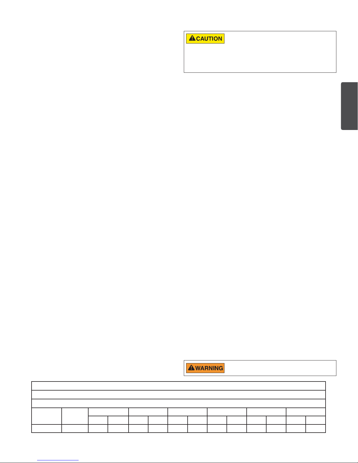
Model # BTUs
220 110,000 50’ 80’ 125’ 250’ 450’ 600’ - - - - - -
3/4” 1” 1-1/4” 1-1/2” 2” 2-1/2”
NG PRO NG PRO NG PRO NG PRO NG PRO NG PRO
Table 1: Gas Pipe Sizing
MAXIMUM EQUIVALENT PIPE LENGTH (FT.)
Natural Gas at 1000 B.T.U. per Cubic Ft.
Propane Gas at 2500 B.T.U. per Cubic Ft.
ULTRATEMP ETI™ Hybrid Heater Installation and User’s Guide
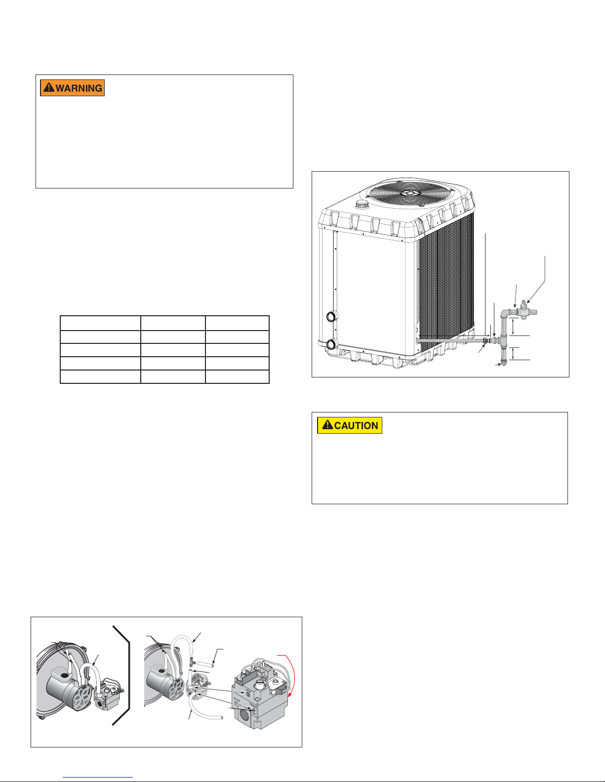
12
Manual
Shut-off
Valve
Sediment Trap
Union
At least 9-in (23 cm)
At least 3-in (8 cm)
1-in (3 cm) Diameter
or larger
(See
Recommended Pipe
Sizes Chart)
18–24-in of 3/4-in
Gas line from
Valve
Bell
Reducer
Checking Gas Pressure Through Gas
Control Valve
Risk of explosion if a unit burning propane gas is
installed in a pit or other low spot. Propane is heavier
than air. Do not install the heater using propane in pits or other locations
where gas might collect. Consult your local building code officials to determine
installation requirements and specific installation restrictions of the heater
relative to propane storage tanks and filling equipment. Installation must meet
the requirements for the Standard for the Storage and Handling of Liquefied
Petroleum Gases, CAN/CSA B149.2 (latest edition) or ANSI/NFPA 58 (latest
edition). Consult local codes and fire protection authorities about specific
installation restrictions.
The UltraTemp ETi™ Hybrid Heater is 100% factory
tested, however Pentair recommends installations
be tested to ensure proper combustion and optimal
performance. During the initial startup, run the heater
continuously for at least 10 minutes and then insert a
probe connected to a combustion analyzer capable of
reading CO and either CO2 or O2 into the exhaust vent.
Wait for the reading to stabilize and confirm values are
consistent with ranges in Table 2. If combustion values are
outside of these ranges, contact technical support.
Measured Gas High Low
CO 150 -
CO
2
O
2
Air-Free CO 199 -
9.2 7.8
7.2 4.8
Table 2
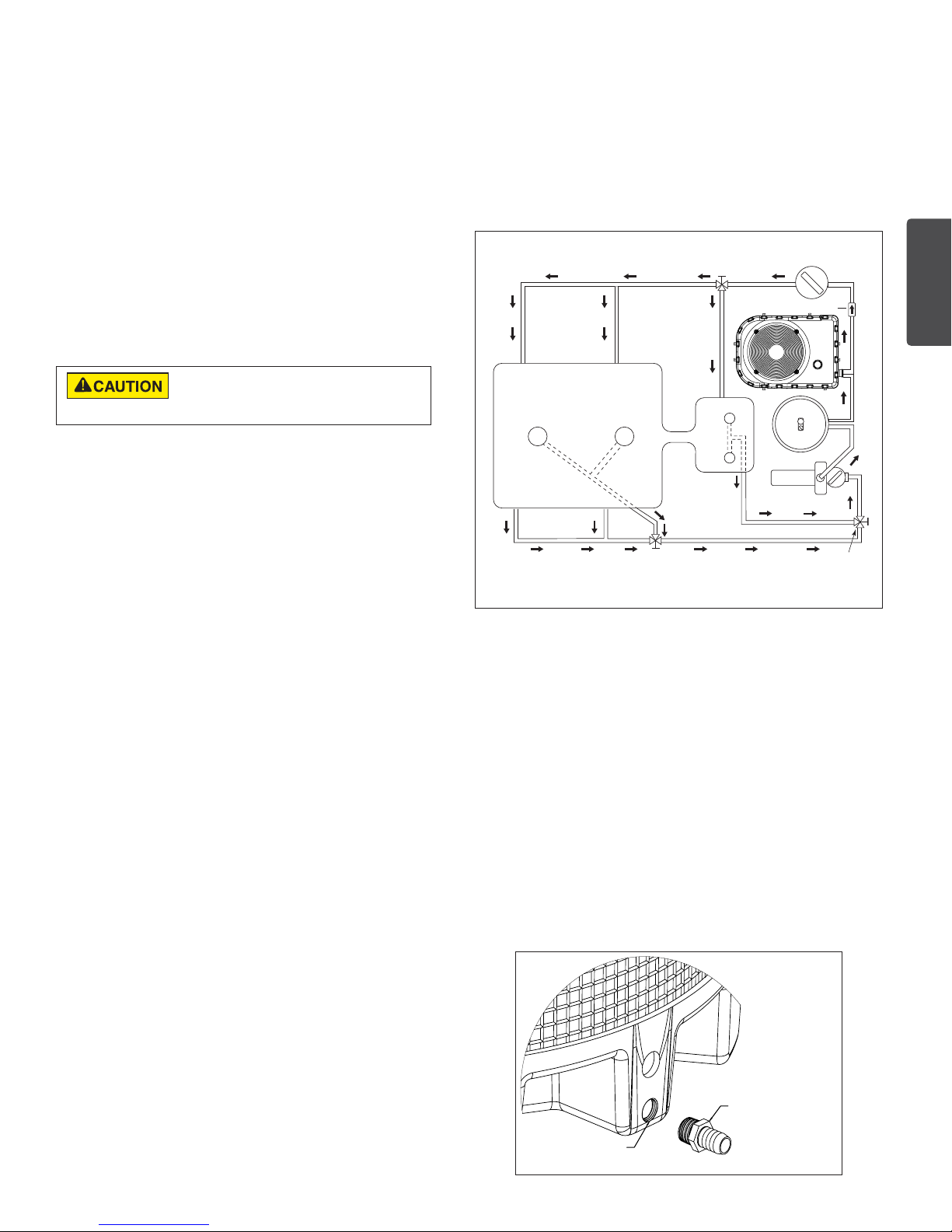
This appliance is equipped with an unconventional gas
control valve that is factory set with a manifold pressure of
–.2” (–0.5cm) wc. Installation or service must be performed
by a qualified installer, service agency, or the gas supplier.
If this control valve is replaced, it must be replaced with an
identical control.
The combination gas valve incorporates dual shut-off
valves and a negative-pressure regulator. For proper
operation, the regulated pressure at the outlet manifold of
the valve must be –0.2” (–0.5cm) wc below the reference
pressure at the blower mixer inlet, and the gas valve
‘VENT’ tap must be connected to the end cap air orifice as
shown in Figure 16.
Do not attempt to adjust the gas input by adjusting the
regulator setting. The correct gas regulator setting is
required to maintain proper combustion and must NOT be
altered.
To Gas
To Air Flow
Switch
To Gas
Valve Vent
To Air Flow
Switch
Valve Vent
To Low Side of
Differential Pressure Gauge
Vent
Pressure Tap
To High Side
of Differential
Pressure Gauge
Pressure Tap
Inlet
Figure 16
Sediment Traps
Install a sediment trap and union located outside
the heater panels in accordance with National code
requirements. Do not use a restrictive gas cock. The
sediment trap shall be either a tee fitting with a capped
nipple in the bottom outlet which can be removed for
cleaning, as shown in Figure 17, or an other device
recognized as an effective sediment trap. All gas piping
should be tested after installation in accordance with local
codes.
Figure 17
Gas Pressure Testing
The heater and its manual shut-off valve must be
disconnected from the gas supply during any pressure
testing of that system at test pressures in excess of 1/2 psi (3.45 Kpa).
Dissipate test pressure in the gas supply line before reconnecting the
heater and its manual shut off valve to gas supply line. Failure to follow
this procedure may damage the gas valve. Over pressurized gas valves
are not covered by warranty. The heater and its gas connections shall be
leak tested before placing the appliance in operation.
Before operating the heater, the heater and its gas
connections must be leak tested. Do NOT use an open
flame to test for leaks. Test all gas connections for leaks
with soapy water or another non-flammable method.
The heater and its individual shut-off valve must be
disconnected from the gas supply piping system during
any pressure testing of that system at test pressures in
excess of 1/2 psig (3.5 kPa). The heater must be isolated
from the gas supply system by closing its individual
manual shut-off valve during any pressure testing of the
gas supply at test pressures equal to or less than 1/2 psig
(3.5 kPa).
Note: Do not use threaded seal tape on gas line pipe
thread. A pipe compound rated for use with natural and
propane gases is recommended. Apply sparingly only on
male pipe ends, leaving the two end threads bare.
ULTRATEMP ETI™ Hybrid Heater Installation and User’s Guide
 Loading...